1
Owner’s Manual
ASTRA
Operation, Safety and Maintenance
Reproduction or translation, in whole or in parts, is not
permitted without prior written consent from Vauxhall Motors
Ltd.
All rights as understood under the copyright laws are explicitly
reserved by Vauxhall Motors Ltd.
All information, illustrations and specifications contained in this
manual are based on the latest production information
available at the time of publication.
The right is reserved to make changes at any time without
notice.
Edition: January 2007.
TS 1612-B-07
A ST R A
©Copyright by Vauxhall Motors Ltd., England.
VAUXHALL Astra
Operation, Safety, Maintenance
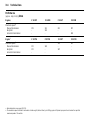
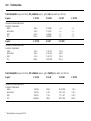
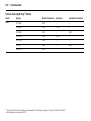
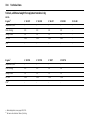
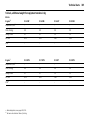
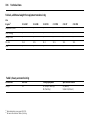
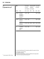
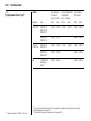
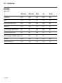
Data specific to your ve hicle
Please enter your vehicle’s data here to keep it ea sily accessible.
This information is available under the section "Technical da ta " as well as on the identification plate and in the Serv ice Booklet.
Fuel
Designati on
Engine oil
Gra de
Viscosity
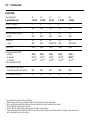
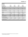
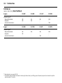
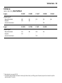
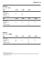
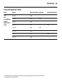
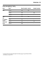
Tyre pressure
Tyre si ze
for loa d wit h 1 p erson and
lig ht lugga ge
wi th full load
S ummer tyres
Front
Rear
Front
Rear
Winter tyres
Front
Rear
Front
Rear
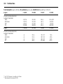
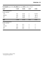
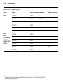
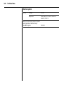
Weights
Perm issi ble gross vehicle weight
–
EC k erb weight
=
Loading
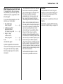
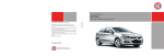
Your Astra
is an intelligent c om bina tion of forwardlooking technology, impressiv e safety ,
env ironmenta l friendliness a nd economy.
It now lies with you to drive your vehicle
safely and ensure that it perform s
perfectly. This O wner’s Manual provides
you with all the necessary information to
that end.
Make sure y our pa ssengers a re awa re
of the p ossible risk of accid ent and injury
which may result from im proper use of the
vehic le.
You m ust alway s comply w ith the sp ecific
laws of the c ountry that y ou are travelling
through. These laws ma y differ from the
inform ation in this Ow ner’s Manual.
When this Manual refers to a workshop
visit, we recommend your Vauxhall
Authorised Repairer.
All Vauxhall Authorised Repairers provide
first class service at reasonable prices.
You will rec eive quick, reliable and
indiv idua l service.
Exp erienced mechanics, trained by
Vauxhall, work according to specific
Vauxhall instructions.
The O wner’s Ma nual should alwa ys be kept
in the vehic le: R eady to hand in the g lov e
compartment.
Make us e of the Owner’s Manual:
z The "In Brief" section will give you an
initial overv iew.
z The ta ble of contents at the beg inning
of the owner’s manual and within the
individual chapters will show y ou where
every thing is.
z Its index will help you find what you
want.
z It w ill fa miliarise you with the
sophisticated technology.
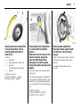
This sym bol signifies:
6 Continue read ing on next pa ge.
3 Items m arked with an asterisk are not
fitted to all v ehicles (model variants,
engine op tions, models specific to one
country, optional equipment, Genuine
Vauxhall Parts and Acc essories).
9 Warnin g
Text marked 9 Warning provides
information on risk of accident or injury.
Disregard of the instructions may lead to
injuries or endanger life.
Inform your passengers accordingly.
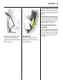
Y ellow arrows in the illustrations serve as
points of reference or indicate some action
to be performed.
Black arrows in the illustrations indicate
a reaction or a second action to be
performed.
Direc tional da ta, e.g. left or right, or front
or back, in the descriptions alway s relate to
the direction of travel.
z It w ill increase y our pleasure in your
vehicle.
Thank y ou for choosing a Vaux hall. We
wish you many hours of plea surable
driving.
z It w ill help you to handle your vehic le
expertly .
Your Vauxhal l Tea m
The O wner’s Manual is designed to be
clearly laid out and easily understood.
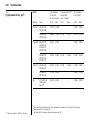
Contents
Comm itment to c ustomer
satisfaction:
Our ai m: to k eep you happy with your
vehicle. All Vauxhall Authorised Repairers
offer first-class serv ice a t competitiv e
prices. Experienced, factory-trained
technicians w ork according to factory
instructions. Y our Authorised Repa irer can
supply you with GEN UINE VAU XHALLAPPRO VED PARTS , which hav e und ergone
stringent quality and precision chec ks, and
of course useful and a ttrac tiv e
VAUXHALL-APPROVED AC CESSO RIES.
Our nam e i s your guara ntee!
For d eta ils of the
Va uxhall Authorised Rep airer Netw ork,
please r ing this number; 0845 090 2044
In Brief . ..... .... ..... .... .... ..... .... ..... .... ..... .... .... . 2
K eys, Doors, Windows, TwinTop ..... .... .. 28
S eats, Interior ..... .... .... ..... .... ..... .... ..... .... .. 64
Instrum ents, Controls ..... .... ..... .... ..... .... 112
Lighting ..... .... ..... .... .... ..... .... ..... .... ..... .... 143
Infotainment system . ..... .... ..... .... ..... .... 151
C lim ate c ontrol . .... .... ..... .... ..... .... ..... .... 154
Driving and op eration ... .... ..... .... ..... .... 176
S elf-help, Vehicle care ... .... ..... .... ..... .... 241
S ervice, Maintenance ..... .... ..... .... ..... .... 294
Technical data . .... .... ..... .... ..... .... ..... .... 308
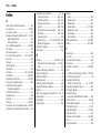
Index . .... ..... .... ..... .... .... ..... .... ..... .... ..... .... 354
2
In Brief
In Brief
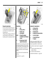
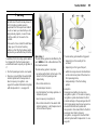
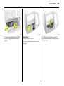
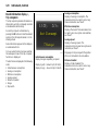
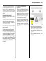
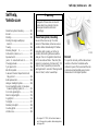
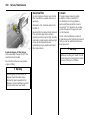
Pict ure no: 16968t.tif
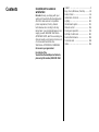
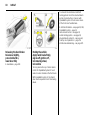
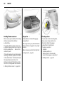
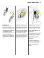
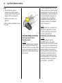
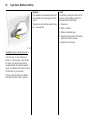
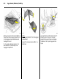
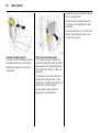
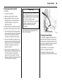
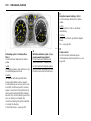
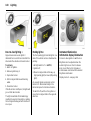
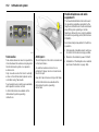
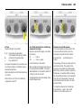
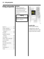
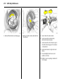
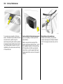
To unlock and open the vehic le:
Press bu tton q ,
pull door handle
6 Door locks – see pag e 47,
key s – see page 28,
electronic im mobiliser – see pag e 29,
ra dio remote control – see page 30,
central locking – see page 38,
anti-theft protection 3 – see p age 39,
Vauxhall a la rm system 3 – see pag e 44,
Tw inTop roof operation 3 – see pag e 56.
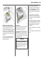
Picture no: 17333t.tif
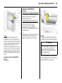
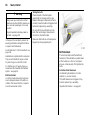
To unlock an d open the vehicle
with the Open&Start System 3 :
Bring electronic key into th e
reception area of the vehicle,
pull handle
6 Open&S tart Sy stem 3 – see page 32.
In Brief
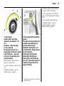
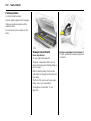
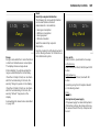
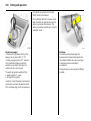
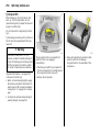
Pi cture no: 16969t.tif
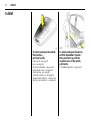
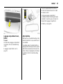
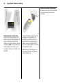
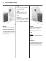
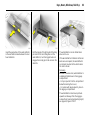
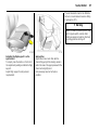
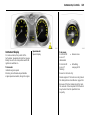
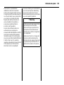
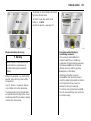
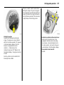
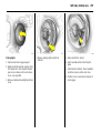
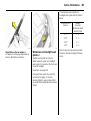
To unlock and o pen th e luggage
compartment:
Press button q on radio remo te
control, or fo r the
Open& Start System 3:
Bring electronic key into the
reception area of the vehic le,
pu ll button below handle
6 Open&S tart-S ystem 3 – page 32,
Radio remote control – page 30,
Central locking system – page 38,
Vauxhall alarm system 3 – page 44.
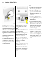
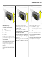
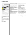
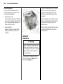
Pict ure no: 16970t.tif
Picture no: 16971t.tif
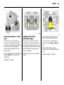
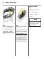
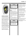
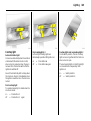
To adjust front seat:
Pull h andle, slide seat,
release handle
Adjust front seat backrests:
Turn handwheel
6 Seat – pa ge 64, seat position – p age 67.
Do not lea n on seat back rest whilst
adjusting it.
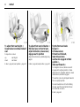
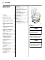
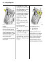
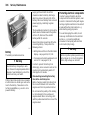
9 Warning
Imp ortant: Do not sit nea rer than 10
inches (25 cm ) from the steering wheel, to
permit safe airbag dep loy ment.
3
Move bac krest to suit sea ting position.
6 Seat – page 64, seat position – page 67.
4
In Brief
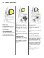
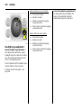
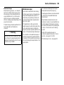
Pi cture no: 16973t.tif
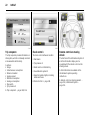
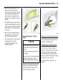
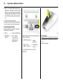
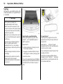
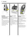
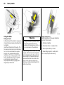
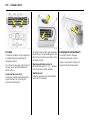
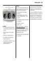
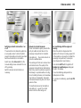
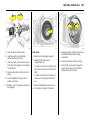
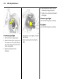
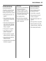
To adjust front seat height 3:
Operate lever o n ou tboard side of
seat
Pump action on lever
up:
seat higher
down:
seat lower
6 Seat – page 64, sea t position – page 67.
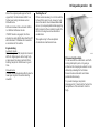
Pict ure no: 16974t.tif
To adjust front seat inclination 3:
Pull inner lever on front of seat,
adjust inclination, release lever,
engage seat in po sition
Ad just the inclination by distributing body
weight.
6 Seat – pa ge 64, seat position – p age 67.
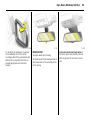
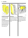
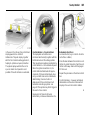
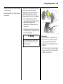
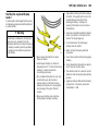
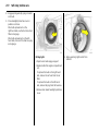
Picture no: 16975t.tif
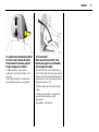
Tip the front seat backs
forward 3:
Lift release lever,
tilt seat bac k forward,
lower release lever,
seat back is en gaged in tilted
position 3,
slide seat forwards 3
To straighten the seat, slide b ack and it
eng ages in its origina l position 3. Raise
release lev er 3 , straighten seat ba ck, lower
release lever, seat b ack eng ages.
The seat bac k can only be tipped forwards
from an upright position.
Panoramic windscreen 3: before folding
the seat, push the head restraints d ow n
and c lose the sun visors.
6 Sea t – pag e 64.
In Brief
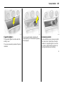
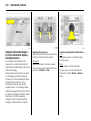
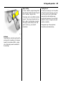
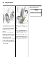
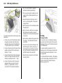
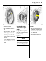
Pi cture no: 16976t.tif
Pict ure no: 16981t.tif
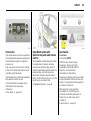
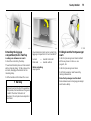
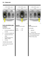
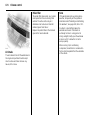
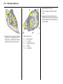
To adjust head restraint height of
front and rear ou tboard seats:
Press button to release, adjust
height, engage in position
To fit seat belt:
Draw seat belt smooth ly from
inertia reel, guide over sho ulder
and engage in buckle
6 Head restra ints – see p age 68,
adjust rear centre head restraint – see
page 68,
head restraint position – see pag e 69,
head restraint removal – see page 69.
The seat b elt must not be twisted at any
point. The lap belt m ust lie snugly a gainst
the body . The front seat backrests must not
be tilted back too far (recommended m ax.
tilting a ngle approx . 25°).
To relea se belt, press red button on belt
buckle.
6 Three-point seat belts – see page 85,
Vauxhall Full Size airbag sy stem –
see p age 92,
seat position – see page 67.
5
6
In Brief
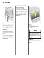
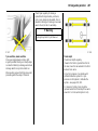
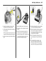
Pi cture no: 16977t.tif
Adjusting interior mirror:
Swivel mirror housing
Swiv el lev er on underside of mirror housing
to red uce daz zle a t nig ht.
6 Mirrors – p age 48,
automatic anti-dazz le interior mirror –
page 49.
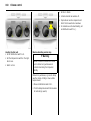
Pict ure no: 16978t.tif
To adjust exterior m irrors
manually:
From inside, swivel lever in
required direction
6 Mirrors – see page 48,
aspherical ex terior mirror – see pa ge 48,
folding exterior m irror – page 48,
heated ex terior mirror – pa ge 157.
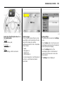
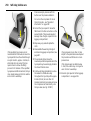
Picture no: 18437T.tif
Electrical exterior mirrors 3
adjust:
Four-way switch in driver’s door
Press mirror sw itch right or left: Four-way
switch adjusts corresponding mirror.
6 Mirrors – see p age 48,
aspherical exterior mirror – see page 48,
folding exterior mirror – page 48,
hea ted exterior m irror – page 157.
In Brief
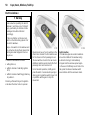
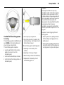
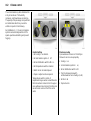
Pi cture no: 16982t.tif
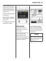
Steering wheel lock and ignition:
Turn key to position 1. Move
steering wheel somewhat to
release loc k
Positions:
0 = Ignition off
1 = Steering released, ig nition off
2 = Ignition on
for diesel engines: preheating
3 = Starting
6 Starting – pa ge 17,
electronic immobiliser – page 29,
parking the vehicle – page 18.
Pict ure no: 17033t.tif
Steering wheel lo ck and ignition
on vehic les with Open&Start
system 3:
Make sure electronic key is in the
interior reception range and
press the Start/Stop button.
Disengage the steering wheel
loc k by moving the steering wheel
slightly
To start the vehicle, also operate brake or
clutch p edal.
To lock the steering wheel, switch ignition
off by pressing the Start/S top button, open
driver’s door and engage steering w heel.
Do not a llow vehicle to move whilst doing
this.
6 Starting – page 17,
electronic im mobiliser – pa ge 29,
parking the v ehicle – pag e 18.
7
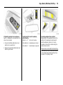
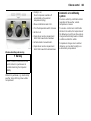
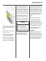
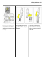
Picture no: 17328t.tif
Steerin g wh eel adjustment:
Move lever down , adju st height
and distance, move lever up,
engage
Adjust steering wheel only when vehicle is
stationary and steering colum n loc k is
released.
6 Vauxhall Full Size airbag sy stem –
pag e 92.
8
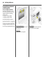
In Brief
In Brief
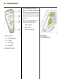
1
Page
Side air v ents ... ..... .... ..... .... .... ..... .... 156
2
Front pa ssenger airbag .... .... ..... .... . 93
3
Centre air v ents .... .... ..... .... .... ..... ... 156
4
Central information display for
time, date, outside temperature,
infotainment sy stem 3 ,
check control 3 .... .... ..... .... .... ..... .... 138
Trip computer 3 ... .... ..... .... .... .128, 134
Clim ate control system 3 . .... ..... ... 168
5
Heated seat (left) 3 . ..... .... .... ..... ... 157
Deflation
detection system 3 .. ..... .... .... ..... .... 217
Tyre pressure
monitoring sy stem 3 ..... .... .... ..... .... 218
Parking distance sensor 3 .... ..... ... 214
Haza rd warning lights .. .... .... ..... .... .. 12
Central locking system . .... .... ..... .... ..40
SPO RT mode 3 ..... .... ..... .... .... ..... .... 210
Heated seat (right) 3 ... .... .... ..... ... 157
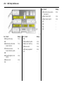
9
Pa ge
Turn signal light, hea dlight flash,
dipped bea m, high beam ..... .... ..... . 11
Switch off delay on 3 ... .... ..... .... ..... 148
Pa rk ing lights 3 ... ..... .... .... ..... .... .... 148
Cruise control 3 .. ..... .... .... ..... .... ..... 212
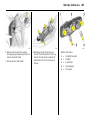
Page
13 S ta rter switch
with imm ob iliser . ..... .... ..... .... ..... .... .... . 7
and
sensor pa nel for emergency operation
O pen&Start system 3 . ..... .... ..... .... .. 35
7
Remote control
on steering wheel 3 . .... .... ..... .... ..... 151
14 Accelerator pedal .... .... ..... .... . 199, 199
8
Instruments . ..... .... ..... .... .... ..... .... ..... 112
16 C lutch pedal 3 .... ..... .... ..... .... ..... .... 199
9
Horn ... ..... .... ..... .... ..... .... .... ..... .... ..... .. 12
Driv er’s Airbag .... ..... .... .... ..... .... ..... . 93
10
Windscreen wiper,
wind screen wash system,
headlight wash system 3 and
rear window w ash
sy stem ..... .... ..... .... ..... .... .... .. 12, 13, 141
6
11
Pa rk ing lights, dipped beam ... ..... 143
Instrument illumination ... ..... .... ..... 148
Fog tail lig ht .... .... ..... .... .... ..... .... ..... 145
Fog lights 3 ..... .... ..... .... .... ..... .... ..... 145
Head lig ht range adjustment 3 .... 146
12
Bonnet release lev er . .... .... ..... .... .... 241
15 Brake pedal .... .... ..... .... .. 199, 221, 221
17 S teering w heel a djustment . ..... .... .... . 7
18 S ta rt/stop button 3 .... ..... .... ..... 17, 32
19 Ashtray 3 ... .... .... ..... .... ..... .... ..... .... . 108
C igarette lighter 3 .. .... ..... .... ..... .... 107
20 C lim ate c ontrol .. ..... .... ..... .... ..... .... 154
21 Infotainment system 3 .... .... ..... .... 151
22 Glove compartment ... .... 34, 110, 156
10
In Brief
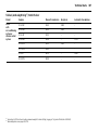
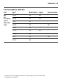
Control indicato rs
0
O pen&S tart system , fault ,
see pages 32, 112.
I
Eng ine oi l pressure,
see page 113.
R
Brak e system , clut ch system,
see pages 114, 221, 302.
v
A
Engine electronics,
gearbox el ect ronics3,
immob iliser,
Diesel fuel filter 3 ,
fault,
see p ages 29, 115, 182, 188,
196, 206.
T
Winter prog ramm e of
aut omatic transmission 3 or
Easytroni c 3,
see pages 180, 186, 193.
1
SPO RT mode of aut omatic
tr ansm issi on 3 or Easytronic 3,
see pages 179, 185, 192.
j
Airb ag syst em s, belt tensi oners,
deployable ant i-roll ba rs 3,
see pages 87, 98, 104.
Easytronic 3 , st art engine 3
see p ages 115, 177.
y
IDS+
Seat occupancy recogniti on 3,
see page 99.
Z
Elec tronic St abili ty Progra mme
(ESP® P lu s) 3,
see page 208.
Continuous Dam ping Control 3 ,
SPORT m ode 3,
see p ages 210, 211.
Exhaust emi ssion 3 ,
see pages 117, 205.
S
Engine oil l ev el 3,
see p ages 116, 298.
u
Anti -lock Bra ke Syst em ,
see page 223.
X
Seat bel t 3,
see pages 88, 114.
8
Exterior light s,
see p ages 116, 143.
!
Q
Door open,
see page 115.
r
Pa rking distance sensor 3 ,
see p age 214.
Prehea ting system 3,
Diesel parti cle filter 3,
see page 118.
p
w
Alternat or,
see page 115.
O
Turn sig nal lig ht s,
see p ages 11, 116.
Deflati on det ec tion system 3 ,
tyre pressure moni toring
system 3,
see pages 118, 217, 219.
W
Coola nt temperat ure,
see pages 115, 300.
Y
Fuel level,
see p ages 116, 119, 202.
B
>
Fog l ights 3,
see p ages 117, 145.
Ad aptiv e for ward lighting 3,
fault
see pages 147, 150.
C
m
Main beam ,
see p ages 11, 117.
C ruise cont rol 3,
see page 212.
r
Fog t ail li ght,
see p ages 117, 145.
v
In Brief
Light
7
8
9
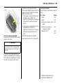
Pi cture no: 16986t.tif
switch:
= Off
= Parking lights
= Dipped beam or main
beam
AUTO = Automatic dipped
beam activation 3
Press button:
>
= Fog lights 3
r
= Fog tail light
6 Lighting – p age 143,
head lig ht control indicator – page 140.
Pict ure no: 16987t.tif
Headlight flash, main beam and
dipped beam:
Headlight
= Pull stalk
flash
towards
steering wheel
Main beam
= Push stalk
Dipped beam = Push stalk
forwards again
or pull toward
steering wheel
6 Main beam, headlight flash – page 144.
Picture no: 16989t.tif
Switch on tu rn signal lights:
Right
= Move stalk up
Left
= Move stalk down
6 Turn signal lights – page 144.
11
12
In Brief
Pi cture no: 16991t.tif
Hazard warning lights:
on
= press ¨
off
= press ¨ again
6 Hazard w arning lights – p age 145.
Pict ure no: 16992t.tif
Activate horn:
Press j in c entre of steering
wh eel
6 Vauxhall Full S ize airbag system –
page 93,
remote control on steering wheel 3 –
page 151.
Picture no: 16993t.tif
Win dscreen wiper:
Move stalk upward
§
= off
$
= timed interval wipe
%
= slow
&
= fast
Move stalk down from p osition §: Single
swipe.
6 Windscreen wiper – pag e 141,
adjustable tim ed interval wipe 3 –
pag e 141,
further notes – p ages 291, 303.
In Brief
Pi cture no: 16995t.tif
Automatic wiping with rain
sen sor 3:
Move stalk upward
$ = automatic wiping with
rain sensor
§
= off
6 Windscreen wiper – page 141,
further notes – pa ges 291, 303.
Pict ure no: 16996t.tif
Operating windscreen and
headlight wash systems 3 :
Pull stalk towards steering wheel
6 Windscreen and headlight w ash sy stems
– page 142,
further notes – pages 291, 303
13
Picture no: 16997t.tif
Activate rear screen wiper 3 an d
wash system 3:
Wiper on
= Stalk forwards
Wiper on
= Stalk forwards
again
Wash
= Hold stalk fully
fo rwards
6 Rear screen wiper and wa sh system –
pag e 142,
further notes – p ages 291, 303.
14
In Brief
Pi cture no: 16998t.tif
Heated rear window,
heated exterior mirrors:
on
= press Ü
off
= press Ü again
6 Air c onditioning – pa ge 154,
heated rear window – page 157.
Pict ure no: 16999t.tif
To demist or defrost windows:
Set air distribution to l,
ro tary switch for temperature
and air flow cloc kwise;
Air con ditioning system 3:
also press bu ttons n ;
Automatic air conditioning
system 3:
press buttons n and v ,
turn rotary switch for
temperature clockwise,
air flo w to A;
Climate c ontrol system 3 :
press button V
6 C lim ate control system 3 – p age 154.
Picture no: 17000t.tif
Set autom atic mo de o n climate
con trol system 3:
Press AUTO,
pre-select tem perature with
rotary knob,
open air vents
6 Climate control system 3 – page 168.
In Brief
Pi cture no: 17001t.tif
Manual transmission:
Reverse: with the vehicle stationary, w ait
3 seconds after de-clutc hing and then pull
up the button on the selector lever a nd
enga ge the gea r.
If the gear does not engag e, set the lever in
neutral, release the clutch pedal and
depress again; then repeat gear selection.
Pict ure no: 17002t.tif
Easytronic 3 :
N
= Idle
o
= D rive positio n
+
= Higher gear
= Lower gear
A/M = Chan ge between
Automatic and Manual
mo de
R
= Reverse gear (with
selector lever lock)
The selector lever must alway s be mov ed in
the appropriate direction as far as it will
go. Upon release, it autom atically returns
to the centre position. Pay heed to the
gear/mode ind icator in the transm ission
display .
The foot brake must be depressed when
starting.
6 Ea sy tronic 3 – pa ge 176.
15
Picture no: 17003t.tif
Automatic transmissio n 3 :
P
= Park position
R
= Reverse gear
N
= Neutral (idle)
D
= Automatic gear selectio n
3
= 1st to 3rd gear
2
= 1st an d 2nd gear
1
= 1st gear
S ta rting only possible in P or N. To m ov e
from P, switch on ignition, depress foot
brak e and press button on selector lever.
Press button on selector lev er to engage P
or R.
P only when v ehicle is stationary, first
apply hand brake
R only when v ehicle is stationary
6 Automatic tra nsmission 3 – page 184.
16
In Brief
To select P or R, press button on selector
lever.
P only w ith v ehicle stopped, first apply
handbrake
R only w hen vehicle is sta tionary
6 Automatic transm ission 3 – see
page 184.
Before starting off, check:
z Tyre pressure and tyre condition –
pages 225, 337.
z Engine oil level a nd fluid levels in engine
compartment – see pages 298 to 305.
z All windows, mirrors, exterior lig hting
and number plates are free from dirt,
snow and ice a nd operational.
z Do not place any objec ts in front of the
rear window, on the instrument panel or
in the area in which the a irba gs inflate.
Pi cture no: 17330t.tif
Automatic transmission
with ActiveSelect 3:
P
= Park position
R
= Reverse gear
N
= Neu tral (idle)
D
= Au to matic gear selection
Selector lever in D to left:
Manual mode
+
= Higher gear
= Lower gear
P or N must b e engaged when starting .
To move from P or N , switch on ig nition,
depress foot brak e a nd press button on
selector lever.
z Seats, seat belts and mirrors are
correctly a djusted .
z Check brakes.
In Brief
17
Press button again to repeat the starting
procedure or switch off the eng ine.
To turn on the ignition, do not press the
brak e or c lutch pedal; just press the button
briefly .
Do not start unless vehicle is stationary .
6 Open&S tart-System 3 – page 32,
Electronic immobiliser – page 29,
Diesel fuel system – page 242.
Pi cture no: 17005t.tif
To start engine:
Operate clutch and brake,
au tomatic transmission 3 in P
or N,
Easytronic 3: Depress brake,
do not ac celerate,
Petrol engine: Turn key to 3;
Diesel engine: Tu rn key to 2, when
control indic ator ! go es out1)
turn key to 3; release key once
engine is running
Before restarting or sw itching off the
engine, turn key back to 0.
To switch on the ignition, only turn the k ey
to 2.
Pict ure no: 17033t.tif
To start engine with Open&Start
system 3:
The electronic key must be inside
reception area inside the c ar,
operate clu tc h or brake,
Automatic transmission 3 in P
or N, Easytronic 3: Depress brake,
do not accelerate,
Petrol engin e: Press bu tton;
Diesel engine: Briefly press
button; when control indicator !
goes out 1 ) press button again for
1 sec ond; release bu tton on ce
engine is running
6 Elec tronic imm obiliser – pag e 29,
Diesel fuel system – page 242.
1)
Prehea ting system switches o n only if ou tsid e
temp era ture is lo w.
18
In Brief
To activa te the mec hanical anti-theft
locking system 3 and the Vauxhall alarm
system 3 press button p tw ic e or with
O pen&Start system 3 touch sensor in one
of the front door handles twice.
6 Further information – see pa ges 29, 198,
O pen&Start system – pa ge 32,
radio remote control – see p age 30,
central loc king sy stem – see page 38,
Vauxhall alarm system 3 – see page 44,
TwinTop roof operation 3 – page 56.
Vehicle decom missioning – see page 307.
Pi cture no: 17006t.tif
Releasing th e hand brake:
Raise lever slightly,
press lock bu tto n,
lower lever fully
6 Handbrake – pa ge 222.
Pict ure no: 17007t.tif
Parking the vehic le:
Apply hand brake firmly,
engine off, ignition off,
loc k steering wheel,
loc k vehicle
To lock , press button p of ra dio remote
control for O pen&Start system 3 touch
sensor in a door handle on the front doors.
With O pen&Start system 3, the driver’s
door must b e opened to lock the steering
wheel.
In Brief
Advice wh en parking:
z Do not p ark the v ehicle on an easy
flam mable surface. The high
temperature of the exhaust sy stem could
ig nite the surface.
z Alwa ys apply the hand brak e firmly.
Ap ply the ha nd brake as firm ly as
possible on uphill or downhill slopes.
To reduce opera ting forc es, depress foot
brake at the same time.
z Close the wind ow s and sun roof 3 or
Tw inTop.
z For manual transmission, select first or
reverse; for automatic transm ission 3
move selector lev er to P, for Easytronic 3
select first or rev erse before switching off
the ignition (note gear display , see
pages 177, 184, 191).
19
z O n vehicles with automa tic
transm ission 3 the key can only be
withdrawn when the selector lever is in
position P. For the O pen&Start Sy stem 3,
"P" fla shes in the gear display for a few
seconds if P is not engaged or the
handbrake is not applied .
That was the most important
information in brief for your first
drive in your vehicle.
z O n vehicles with Easytronic 3 control
indicator R flashes for a few second s
after the ignition is switched off if the
hand brak e has not been applied– see
page 182.
The other pages o f this chapter
con tain a summary of the
noteworthy functions of your
vehicle.
z With the O pen&Start system 3 the
eng ine can only be switched off when the
car is stationa ry .
z Turn steering wheel until the steering
lock p erceptibly eng ages (Anti-theft
protection) after first withdrawing the
ignition key ; for Op en&Start-Sy stem 3
switch off ignition and open driver’ s
door.
z The engine cooling fans may run a fter
the engine has been switched off – see
page 297.
6 Further information – pages 306, 307.
The remain ing ch apters of the
Owner’s Manual contain
impo rtant information on
operatio n, safety and
maintenance as well as a
com plete index.
20
In Brief
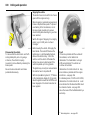
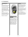
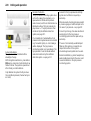
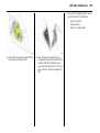
Pi cture no: 17009t.tif
Vauxhall Full Size airbag system
The Vauxhall Full Size airbag system
consists of several separate sy stems.
Front airb ag system
The front airbag system will be triggered in
the event of a serious ac cident involving a
frontal impact and forms safety cushions
for the driver and front passenger. The
forward movement of the driver and front
passenger is checked and the risk of
injuries to the upper body a nd head
thereby substantially reduced.
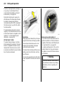
Pict ure no: 17110t.tif
Side airb ag system 3
The sid e airbag is triggered in the event of
a side-on c ollision to form a safety cushion
for the driver or front passenger in the
respective door area. This substantially
reduces the risk of injury to the upp er body
and pelv is.
Picture no: 17351t.tif
C ur tain ai rbag syst em 3
The curtain a irba g system triggers in case
of a side-on collision and provid es a safety
barrier in the hea d area on the respective
side of the vehic le. This reduces the risk of
injury to the hea d considerab ly in case of a
side-on collision.
6 Vauxhall Full Size airbag sy stem –
pag e 92.
In Brief
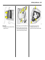
Pi cture no: 17011t.tif
Picture no: S0013209.ti f
21
Picture no: 17013t.tif
Active head restraints 3 on front
seats
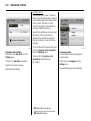
Operating menus in th e
information display 3
S elec tion using multi-function button 3:
rotate and press multi-function button.
In the event of a rear-end impa ct, the
active head restraints tilt forward a little.
The head is more effectiv ely supported by
the head restraint and the danger of
injuries caused by whiplash in the neck
area is reduced.
Menu options are selected using menus
and using the arrow keys the multi-function
button of the I nfotainment system 3 or the
left-hand adjuster wheel 3 on the steering
wheel. The respective menu options are
shown on the d isplay .
To exit a m enu, turn the m ulti-func tion
button left or right to Return or M ain and
select.
Active head restraints are id entified by the
lettering ACTIVE on the head restraint
guide sleev es.
Select with the arrow keys 3: press right or
left key.
6 Informa tion Display – page 122.
6 Headrests – page 68.
S elec tion with left adjuster wheel on
steering wheel 3: turn adjuster wheel and
press.
22
In Brief
Ü
Board Computer
BC 1
19,5° 19:36
All values
BC 2
Timer
257.0
40
1
Ø
8
7.0
Ø 31.0
Tyres
miles
Coolant level
mph
ch eck
gal
mpg
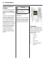
Pi cture no: 17344t.tif
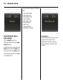
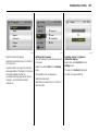
Trip computer
3
The trip computers provide information on
driving data, which is continually recorded
and evaluated electronically .
Functions:
z Rang e
z Instantaneous consumption
z Distance tra velled
z Av erage speed
z Effective consump tion
z Av erage consump tion
z Stop watch
z Ty re pressure 3
6 Trip computer 3 – pa ges 128, 134.
OK
Pict ure no: 17339t.tif
Check co ntro l 3
The check control software monitors
z Fluid levels
z Tyre pressure 3
z Radio remote control battery
z Vauxhall alarm system 3
z Imp ortant exterior lights, including
cables and fuses.
6 C heck-Control 3 – page 138.
Picture no: 17015t.tif
Remo te control o n steering
wheel 3
The functions of the infotainm ent system 3
and the informa tion display can be
operated w ith the rem ote control on the
steering wheel.
Further information is availab le in the
infota inm ent system operating
instructions.
6 Remote control on steering wheel 3 –
pag e 151, Infotainment System –
pag e 151.
In Brief
Pi cture no: 17026t.tif
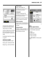
Twin Audio
3
Twin Aud io allows rear seat occupants the
choice between the audio source played on
the infotainment system or a separate
audio source.
O nly an audio source that is not currently
active on the infotainment system can be
controlled using Twin Audio.
Two headphone connections are availab le,
with separate volume controls.
Further information is available in the
infotainment sy stem operating
instructions.
6 Tw in Audio 3 – pa ge 152.
Pict ure no: 17333t.tif
Picture no: 17961t.tif
Open&Start system with
electronic key and radio remove
control 3
Sport mo de
The O pen&Start system allows the vehic le
to be lock ed and unlocked, including
mechanical a nti-theft locking system 3
and the Va ux ha ll alarm sy stem 3 without a
mechanical k ey and the engine to b e
started and stopped using a start/stop
button. All the driver has to do is carry the
electronic k ey around w ith him.
S PO RT mode is used to change
dam ping 3, steering 3, throttle
app lic ation a nd the shift p oint for
Easy tronic 3 and automatic
transmission 3 while driving.
6 O pen&Start S ystem 3 – p age 32.
23
3
To act ivat e
Press button SPORT.
Damp ing and steering become more direct
and p rov ide b etter contact with the road
surfac e. The engine reacts more quickly to
acc elerator m ov ements.
With Easytronic 3 and automatic
transmission 3, the shift times are
shortened a nd shifting takes p lace a t
higher revs (not with cruise control
ena bled 3).
6 Sport mode 3 – page 210.
24
In Brief
Ü Board Computer
BC 1
BC 2
Timer
Tyres
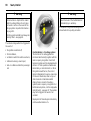
Pi cture no: 17018t.tif
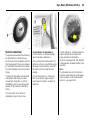
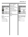
Deflation D etection System
(D DS) 3
The d eflation detection sy stem
continuously monitors the speed of all
wheels while driving. If a ty re loses
pressure, it g rows smaller and therefore
rotates m ore quic kly than the other wheels.
If the system detects a difference in speed,
the c ontrol indicator w illuminates in red.
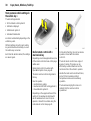
Pict ure no: 17019t.tif
After tyre pressure is corrected or a ty re or
wheel is c hanged, the system m ust be
initialised by pressing the DDS button.
6 Tyre deflation detection system 3 –
page 217.
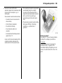
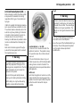
Picture no: 17334t.tif
Tyre pressure monitoring
system 3
The tyre p ressure monitoring system
continually checks the pressure and speed
of all four wheels while driving.
A pressure sensor is insta lled in ea ch wheel.
The inflation pressures of the individual
wheels are tra nsmitted to a controller,
where they are compared.
The current tyre pressures ca n be
displayed on the graphical informa tion
display or the colour information d isplay 3.
Deviating tyre pressures are displayed in
the form of messages on the information
display whilst driving.
6 Tyre pressure monitoring system 3 –
pag e 217.
In Brief
Pi cture no: 17126t.tif
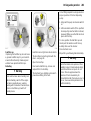
Adaptive Forward Lighting
(AFL) 3
improves lig hting in curves (curve lighting )
on vehicles with Bi-Xenon headlight
system.
Picture no:
Curve lig hting
The Xenon light bea m pivots based on
steering wheel position a nd speed (from
approx. 6 m ph / 10 km /h).
Motorwa y lig hting
At higher speeds and continuous straight
ahead trav el, the dipped beam
autom atic ally raises slightly , thereby
increasing headlight range.
6 Adaptive driving lights 3 – page 147.
25
Picture no: 17979t.tif
Panoramic windscreen
3
To open:
Turn the handle to the right and m ov e the
roof lining rearward to a suitable position.
To close:
Move the roof lining forward to a suitable
position. When moved all the w ay forw ard,
the roof lining enga ges in position.
6 Panoram ic roof 3 – p age 53.
26
In Brief
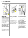
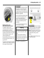
Pi cture no: 17203t.tif
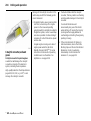
Parking distance senso r 3
When rev erse gear is selected, the Pa rk ing
distance sensor sw itc hes itself on
automatically.
The p arking dista nce sensor can also be
activated at speeds of less than 15 m ph (25
km/h) by pressing the r button on the
instrument panel.
If the v ehicle approaches an obstacle when
rev ersing, a series of signals can be heard
in the vehicle interior. The interva l between
the signals bec om es shorter as the
distance is reduc ed. If the distance is less
than 30 c m, the signal w ill be c ontinuous.
6 Park ing distance sensor 3 – p age 214.
Pict ure no: 17092t.tif
Cargo box
3
Collapsible box to divide the lugga ge
compartment.
The cargo b ox may only be loaded when
the back rests a re eng aged in an upright
position.
When removing, start w ith the right half.
6 C argo Box 3 – pag e 81.
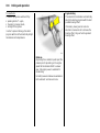
Picture no: 17087t.tif
FlexOrganizer 3
The side walls contain retaining strips,
where va rious components can be
attached to divide the lugg age
compa rtm ent or fasten loads.
The sy stem consists of
z Adapters
z Variable partition net
z Mesh pockets for the side walls
z Hooks in the luggage compartment
6 FlexO rg aniz er 3 – pag e 80.
In Brief
27
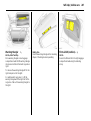
The roof is opera ted w ith the buttons on
the roof console abov e the mirror or with
the remote control.
To improve luggage compa rtm ent
acc essibility, the electric loading aid makes
it possib le to raise the open roof when it is
stowed in the luggage compartment.
6 TwinTop – see page 56.
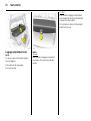
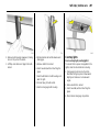
Pi cture no: 17980t.tif
Luggage compartment cover,
Estate
To open:
Press ha nd le on luggage compa rtm ent
cover down. The cover automa tica lly
unrolls.
6 Luggage compa rtm ent cover 3 –
page 76.
Pict ure no: 17981t.tif
Astra TwinTop
With TwinTop, a c onvertible ha rd top , Astra
unites the benefits of a coup e with those of
a convertible.
To op tim ise safety, the Astra TwinTop is
equipped with a rollover protection system
with reinforced windscreen frame and the
choice of fix ed or deployable anti-roll ba rs
in addition to the front and sid e a irba g
sy stems.
28
Keys, Doors, Windows, TwinTop
Keys, Doors, Windows,
TwinTop
Replacement keys
The key number is specified in the vehic le
docum ents and in the C ar Pass 3.
The key is a c onstituent of the electronic
immobiliser. Ordering keys from a Vauxhall
Authorised Repairer g uarantees problem free op eration of the electronic
immobiliser.
Replacem ent keys ... ..... .... ..... .... .... ..... .
Ca r Pass... .... .... ..... .... ..... .... ..... .... .... ..... .
Key with foldaw ay key section 3 . ..... .
Electronic immobiliser... .... ..... .... .... ..... .
Store personal vehicle settings in the
vehicle key 3 ..... .... ..... .... ..... .... .... ..... .
Radio remote control with 3
mec hanical key . .... ..... .... ..... .... .... ..... .
O pen&Start system 3 ... .... ..... .... .... ..... .
Central locking system . .... ..... .... .... ..... .
Fault when locking or unlocking... ..... .
Lug gage compartment .... ..... .... .... ..... .
Vauxhall alarm system 3. ..... .... .... ..... .
Child safety locks 3 . ..... .... ..... .... .... ..... .
Ex terior mirrors..... .... ..... .... ..... .... .... ..... .
Interior mirror .. ..... .... ..... .... ..... .... .... ..... .
Electric windows 3 ... ..... .... ..... .... .... ..... .
Panoramic windscreen 3 . ..... .... .... ..... .
Sun roof 3 ... .... ..... .... ..... .... ..... .... .... ..... .
TwinTop ... .... .... ..... .... ..... .... ..... .... .... ..... .
28
28
28
29
30
30
32
38
42
43
44
47
48
49
50
53
54
56
When electronic k eys of the Open&S tart
sy stem are being replaced , all keys must be
ha nded to the dea ler for programming.
Keep the sp are k ey in a safe spot.
Locks, see pa ge 291, Op en&Start system,
electronic k eys, see pa ge 32.
Car Pass
The Ca r Pass contains a ll of the vehicle’s
data and should therefore not be k ept in
the vehicle.
Have your Ca r Pa ss on hand when
consulting a Vaux hall Authorised Repairer.
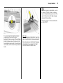
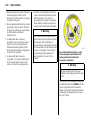
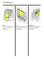
Picture no: 17027t.tif
Key with foldaway key section 3
Press button to extend. Press button to
retrac t; key section eng ages audibly .
Keys, Doors, Windows, TwinTo p
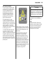
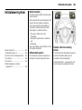
Pi cture no: 17349t.tif
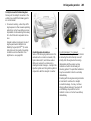
Electronic immo biliser
The sy stem checks whether the vehicle m ay
be sta rted with the mec hanical key or
electronic key of the O pen&S ta rt sy stem 3
that is being used . If the key is recognised
as "authorised " the v ehicle ca n b e started.
The chec k ta kes place v ia a transponder in
the k ey.
The electronic imm ob iliser activates itself
automatically after the key has been
rem ov ed from the ignition or, with the
O pen&Start system 3, w hen the engine is
switched off by pressing the Start/Stop
button.
The c od e number of the electronic
immobiliser is giv en in the C ar Pass.
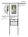
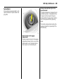
Pict ure no: 17033t.tif
Control i nd icator for imm obiliser A
Control indica tor A illuminates briefly
when the ig nition is sw itched on.
If the control indicator flashes w hen the
ignition is on, there is a fault in the sy stem;
the engine cannot be started. S witc h off
the ignition and then rep eat the start
attempt.
If the control indicator A continues to
flash, try to start the engine using the
second key and c ontact a workshop for
assista nce.
29
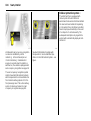
Picture no: 17028t.tif
If control indicator A illuminates after the
engine is started, there is a fault in the
engine electronics or transm ission
electronics 3 (see pages 182, 188, 196, 206)
or there is water in the diesel fuel filter 3 (see
page 300).
Not e
The immobiliser does not lock the doors.
Therefore, after leaving the v ehicle a lways
lock it and switch on the Vaux hall alarm
system 3 – see p ages 38, 45.
30
Keys, Doors, Windows, TwinTop
Store person al veh icle settin gs in
the vehic le key 3
The last settings selec ted
z for the climate control system 3
z information display 3
z Infotainment system 3
z instrum ent illumination
are stored autom atically depending on the
vehic le key used .
Different settings stored for ea ch vehicle
key are retrieved autom atically on use of
the v ehicle key concerned .
Ea ch time the vehicle is loc ked, the settings
are sa ved again.
Pict ure no: 17029t.tif
Radio remote c ontrol with
mec hanical key
3
Depend ing on v ehicle eq uipm ent level, one
of the rem ote controls shown on this page
will be used.
Radio rem ote control in version with
Open&S tart sy stem 3 see page 32.
The radio remote control is integrated in
the key.
Used to operate:
z central lock ing sy stem,
z mechanical anti-theft locking system 3,
z Vauxhall alarm system 3.
Depend ing on the equip ment level of the
vehicle 3, the windows of vehicles with
electric windows in a ll doors 3 can be
op ened or closed from outside using the
ra dio remote control. See pa ge 41.
Picture no: 17030t.tif
O n the Astra TwinTop, the roof can also be
opened or closed with the remote
control 3.
The ra dio remote control has a rang e of
app rox . 5 metres. This ra ng e can be
affec ted by outside influences. Aim the
remote control at the vehicle to operate.
Handle the radio rem ote control with care,
protec t it from moisture and high
temperatures a nd avoid unnecessary
operation.
The ha zard warning lights come on to
indicate that the remote c ontrol is
operational.
Keys, Doors, Windows, TwinTo p
Centra l locki ng, mechanic al anti -theft
lock ing system 3,
see page 38.
Vauxha ll ala rm system 3,
see page 44.
Elec tric w indows 3,
see page 50.
Astra Tw inTop,
see page 56.
31
Fault
If the centra l locking system ca nnot be
op erated with the rad io remote control, it
may be d ue to the following:
z The ra nge of the ra dio remote control
has been exceeded.
z Radio remote control battery v oltage is
too low. Ba ttery replacement - see right
hand column.
z Frequent, repeated op eration of the
radio remote c ontrol outside the
rec eption range of the vehic le (e.g. too
far from vehicle, remote control is then
no longer recognised). Remote control
synchronisation - see right hand c olumn.
z If the central locking system is
overloa ded as a result of repeated
opera tion at short intervals. The power
sup ply is cut off for a brief period.
z Interference from hig her-power rad io
wav es from other sources.
To eliminate the cause of a fault, we
recommend contacting a workshop for
assista nce.
Open driver’ s d oor w ith k ey , see page 42.
Rem ote control b attery rep lacement
Replace the battery as soon as the range
of the radio remote control begins to
shrink.
Picture no: 17031t.tif
K ey with folda way k ey section
Extend key , see page 28. Open radio
remote control. Replace battery - battery
typ e, see pa ge 348 - noting installation
position. Close radio remote control.
Mak e sure that you dispose of old batteries
in accordance with env ironmental
protec tion regulations.
K ey with fix ed key section
Hav e the battery cha nged by a workshop.
Synchronise the radio remot e c ont rol
aft er m alfuncti ons or b attery change
After c hanging the battery , unlock the
door w ith the key in the lock. Turning on the
ignition will sy nchronise the radio rem ote
control.
32
Keys, Doors, Windows, TwinTop
Pi cture no: 17333t.tif
Open& Start system
3
The O pen&S ta rt sy stem allows the v ehicle
to be locked and unlocked , including the
mechanic al anti-theft locking system 3
and the Vauxhall alarm system 3, and the
engine to be started and stopped without
a mecha nica l key. All the driver has to do is
keep the key on his person.
Dep ending on the equipment level of the
vehic le 3 , the w indows of vehicles with
electric windows in all doors 3 can be
opened or closed from outside using the
rem ote control of the electronic key. S ee
page 41.
O n the Astra TwinTop, the roof can also be
opened or closed with the remote control 3
of the electronic key.
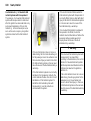
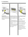
Pict ure no: 17032t.tif
The electronic key must be within the
externa l reception rang e ab out 1 m etre
from the vehicle in order to lock and unlock
the vehicle.
If the electronic key is rec og nized as
"authorised" , the vehicle can be unlock ed
by pulling a door handle or the knob
beneath the tailgate hand le and the doors
and the tailga te can b e opened.
Picture no: 17033t.tif
When the S tart/Stop b utton is pressed, the
system re-check s the authorisation. The
electronic key has to be recognised in the
interior in order to d o this. After the key has
been authorised the ignition switches on.
At the sam e time, the electronic
imm ob iliser is switched off a nd the electromechanical steering column lock is
deactivated. Pressing the Start/S top button
aga in with the brake or clutch pedal
depressed or in P or N with automatic
transmission 3 starts the engine. Press the
button for at lea st one second with the
vehicle stationary or hold until the eng ine
starts.
Keys, Doors, Windows, TwinTo p
33
If the brake or clutch peda l is depressed ,
the engine ca n be started right away with
a single press on the Start/Stop button.
Releasing the S tart/Stop b utton interrupts
the starting proced ure.
The engine and the ignition are switched
off by pressing the Start/S top button again.
The v ehicle must b e stationa ry . The
immobiliser is activ ated a t the same time.
If the ignition has been switched off and
the vehicle is stationa ry , the steering wheel
lock ac tiv ates automatically when the
driver’s door is opened or closed.
The electronic key m ust be within the
interior reception in order to switch the
ignition on or off. We recomm end that the
driver carries the electronic k ey on his or
her p erson. If the electronic key is not
recognised, try a different position for the
key.
Do not put the electronic key in the
luggage compartment or in front of the
inform ation d isplay .
Pict ure no: 17034t.tif
The vehic le is locked from the outsid e with
the doors closed by touching the sensor
panel in the door ha ndle of one of the front
doors. The electronic key must be within
the external reception range of
approximately one metre from the vehic le.
The O pen&Start sy stem 3 does not the lock
the vehicle automatically if the electronic
key is outside the external reception range
of approximately one metre from the
vehicle.
Picture no: 17035t.tif
Ra dio remote control
The vehicle can be locked and unlocked by
conventional means using the radio
remote control with the b uttons on the
electronic key.
In ad dition, the mechanical anti-theft
locking system and Vauxhall a larm sy stem
can be armed and disabled using the radio
remote control. Depending on the
equipment level of the vehicle 3 , the
windows of vehicles with electric windows
in a ll doors 3 ca n be opened or closed from
outside using the radio remote c ontrol.
6
34
Keys, Doors, Windows, TwinTop
If the control indicator 0 is perma nently
on, an error has occ urred in the system .
Lock or unlock vehicle using the radio
remote control or the emerg ency key if
nec essary – see pag e 42, or try using the
spare key .
The rad io remote control has a ra nge of
approx. 5 metres. This range can be
affected by outside influenc es. Aim the
rem ote control at the v ehicle to operate.
Handle the radio remote control with care,
protect it from moisture and high
tem peratures and avoid unnecessary
opera tion.
If 0 illumina tes, this can also mean that
the steering wheel loc k is still locked : move
steering wheel to and fro a little and press
S ta rt/Stop button again.
The haz ard warning lights c om e on to
indicate tha t the remote control is
opera tional.
Centra l locki ng, mechanic al anti -theft
lock ing system 3,
see page 38.
Vauxha ll ala rm system 3,
see page 44.
Elec tric w indows 3,
see page 50.
Astra Tw inTop,
see page 56.
Pict ure no: 17036t.tif
Control i nd icator for Open&St art
system 0
If the control indicator flashes 0 with the
ignition switched on or with the engine
running an opera ting error has occurred,
e.g. the electronic key is no longer w ithin
the rec eption range of the vehic le interior.
During the next starting procedure the
engine may not be a ble to be started. Press
Start/S top key somewhat longer to sw itch
the ignition off.
Flashing of the 0 can a lso b e an indication
of com plete failure of the electronic key. In
this case operation is only possible using
the emergency facility – see page 35.
InSP3 in the service display or an
appropriate m essag e in the information 3
display indicates that the battery of the
electronic k ey need s replacing – see
page 36.
If 0 illumina tes while d riv ing, there is a
system fa ult. Contact a w orkshop
imm ediately.
Emergency operation – see page 35.
Locka ble glov ebox, Astra TwinTop wi th
O pen&Start system 3
In ad dition to the electronic key of the
O pen&Start sy stem, there is a standa rd key
without remote control for the glove
compa rtm ent lock.
Keys, Doors, Windows, TwinTo p
Pi cture no: 17037t.tif
Emergenc y operat ion
If the Open&Start system fails or the
electronic key (control indicator 0 flashes
or permanently on) the driver’s door can b e
locked or unlock ed with the emergency key
in the electronic key: press loc king
mechanism on underside and remove cap
toward the front by apply ing gentle
pressure to the cap. Push emergency key
towards the outsid e over the detent and
rem ov e.
Pict ure no: 17038t.tif
Only the driver’ s door can be locked and
unlocked using the emergency key. Unlock
the entire vehic le as d escribed on page 42.
In the version with Vauxhall alarm
sy stem 3 the alarm m ay be triggered w hen
the vehicle is unloc ked. Switch ignition on
to deactiv ate ala rm and release the
steering column lock: hold electronic key a t
marked position on the steering column
panelling and p ress the Start/S top button.
Repeat procedure if necessary .
35
Picture no: 18439t.tif
To sta rt the engine, hold the electronic key
at the marked position, dep ress b ra ke
pedal or clutch pedal or in vehicles with
automatic transmission 3 d epress brake
pedal and engage P or N, Then press the
S ta rt/Stop button.
Press start/stop button for at least 1 second
to switch the engine off. Lock all d oors
except driver’ s door as described on
pag e 42. Unlock driver’s door with
emergency k ey.
This fa cility is for emergency use only .
Replace the battery of the electronic key a s
soon as possible or hav e the sy stem
repaired. Contact a w ork shop for
assistance.
36
Keys, Doors, Windows, TwinTop
Ra dio remote control synchronisation
The radio remote control synchronises itself
automatically during every starting
procedure.
Pi cture no: 17040t.tif
Replac ing bat tery in electronic key
Replace the battery immediately if the
system is no long er working prop erly or the
range of the radio remote c ontrol is
red ucing. The need for a battery change is
indicated via InSP3 in the service d isplay or,
in vehic les with check control 3 , by an
appropriate message in the display. See
page 120.
Pict ure no: 17041t.tif
To replace the b attery, press the locking
mechanism on the underside of the
electronic k ey and rem ov e the cover
tow ards the front b y app lying gentle
pressure - see page 35, fig ure 17037 T.
Push off cover w ith emblem on the button
side towards the outsid e.
Replace battery, for ba ttery ty pe – see
page 348, pay attention to installation
position. Enga ge c aps.
Keys, Doors, Windows, TwinTo p
Fault in O pen&Star t system or ra dio
remote control
If the centra l locking c annot be operated or
the engine ca nnot be started, the cause
may be one of the following:
z Elec tronic key out of rec eption range, or
out of range of radio rem ote control.
z Radio rem ote control battery v oltag e too
low – see previous pag e for instructions
on how to c hange battery.
z Freq uent, rep eated opera tion of the
ra dio remote control outside the
recep tion range (e. g. too far from
vehicle, rem ote control is then no longer
recognised).
z If the central locking system is
overloa ded as a result of repeated
opera tion at short intervals. The power
sup ply is cut off for a brief period.
z Interference from hig her-power rad io
wav es from other sources.
37
To elim inate the fault, change the position
of the elec tronic k ey or ra dio remote
control or change the battery in the rad io
remote control. If the fault persists, contact
a work shop for assistance.
Emergency operation – see page 35.
38
Keys, Doors, Windows, TwinTop
Pi cture no: 16968t.tif
Cen tral locking system
For doors, b oot lid/tailgate and tank flap.
To unlock
Remote control with mechanica l key
Press button q on radio remote control.
To open the door, pull the ha nd le. O pen
the lugga ge c om partment by pulling the
knob under the tailgate handle.
Pict ure no: 17032t.tif
Open&S tart sy stem with electronic key 3
The electronic key must be within the
outside reception range of the v ehicle.
Unlock the vehicle by pulling a door handle
or the knob below the ta ilg ate handle
– or – –
Press button q of the electronic key’s
remote control.
Picture no: 17042t.tif
To lock
C lose doors, lugg age com partment a nd
tank flap.
Rad io remote control with m echanical key
Press button p on radio remote control.
Keys, Doors, Windows, TwinTo p
39
Mec hanical a nti-theft lock ing system 3,
9 Warning
Do not use the system if there are people
in the vehicle! The d oors cannot be
unloc ked from inside.
Pi cture no: 17034t.tif
O pen&Start system with electronic k ey 3
The electronic key m ust be within the
outside reception range of the vehicle.
There m ust be no electronic keys inside the
vehic le. Touching the sensor in the door
handle of the driver’s or front passenger’ s
door locks all doors and the lugg age
compartment
– or – –
Press button p of the elec tronic key’ s
rem ote control again.
Picture no: 17043t.tif
Rad io remote control with m echanical key
All doors must be c losed . At the la test
15 seconds after locking, p ress b utton p
of the ra dio remote control again.
Lock buttons on all doors are positioned
such tha t doors ca nnot be opened.
If the ignition wa s on, the driver’s door
must be opened and closed once so that
the vehicle can be secured .
40
Keys, Doors, Windows, TwinTop
Not e
z If the driv er’s door is not closed properly ,
the central loc king sy stem will not lock.
z To loc k the d oors from within (e.g . to
prevent unw anted entry from outside),
press central locking switch m in the
centre console.
z After unlock ing with the key in the lock
and opening the driver’ s door, the entire
vehicle is unlocked.
Pi cture no: 17044t.tif
O pen&Start system with electronic k ey 3
All doors must be c losed . The electronic key
must b e within the outsid e reception range
of the vehicle. Touch the sensor in the door
handle of the driver’s or front passenger’ s
door again within 15 seconds after loc king
– or –
Press button p of the elec tronic key’ s
rem ote control again.
All doors are sec ured aga inst opening.
If the ignition was on, the driver’ s door
must be opened and closed once so tha t
the v ehicle can be secured.
Pict ure no: 17045t.tif
Central l oc king b utton for lock ing and
unl ocking the d oors from inside the
vehicle
Press button m in the centre console: doors
are locked or unlocked.
The LED in the central locking b utton m
illuminates for around 2 minutes after
lock ing with the remote control.
If the doors are loc ked from the insid e
during the journey using the central loc king
button, the LED m illuminates
permanently .
If the key is in the ignition, lock ing is only
possible if all doors a re closed.
When the mechanical anti-theft locking
sy stem 3 is ac tiv e – see previous page –
the doors cannot b e unlocked with this
button.
z If locked via the central locking system,
the doors ca n a lso be opened by pulling
the insid e door handles. The central
loc king sy stem is also unlock ed a t this
time (not possible on Astra TwinTop
when the roof is open).
z Locked doors unlock automatically in
the event of an a ccident of a certain
severity (to allow ex ternal help to gain
access). The haz ard warning lights a nd
courtesy light also come on. For this to
occur, the k ey must b e in the starter
switch.
Keys, Doors, Windows, TwinTo p
41
z With the Open&S tart sy stem 3 the
vehicle cannot be unlocked until
2 seconds after locking. Within this time,
a door handle c an be pulled or the
button beneath the tailgate handle
op erated to check whether the vehic le
is locked.
z The Op en&Start system 3 does not lock
the vehicle autom atically if the elec tronic
key is outside the reception range of the
vehicle (more than 1 metre aw ay from
the vehic le).
z When using the O pen&S tart sy stem 3,
there m ust not be an electronic key
inside the vehicle when locking.
z The locking sensors in the door ha ndles
must be kept clean to ensure
unrestricted functionality of the
Open&S tart sy stem 3 .
Pict ure no: 17046t.tif
Operat ing the wind ow s 3 from t he
out si de
9 Warning
Take care when operating the electric
windows. Risk of injury , particularly to
children.
Vehicle passeng ers should be inform ed
accordingly.
K eep a close watch on the windows when
closing them. Ensure that nothing
becomes trapped in them as they move.
Depend ing on the equip ment level of the
vehicle 3, the windows of vehicles with
electric windows in a ll doors 3 can be
op ened or closed from outside:
Picture no: 17034t.tif
Rad io remote control with m echanical key
Hold button q or p on the radio remote
control dep ressed until all windows ha ve
opened or com pletely closed.
O pen&Start system with electronic key 3
Hold down button q of radio remote
control to open. To close, hold down
button p or touch sensor in door hand le
for longer. The electronic key must be
recognised within the external reception
range. It is advisable for the driver to k eep
the electronic k ey on his person.
Further information on windows – see
pag e 50.
42
Keys, Doors, Windows, TwinTop
Fault
z If the centra l loc king sy stem is
ov erloaded as a result of repeated
op eration at short interv als. The power
supply is c ut off for a b rief period.
For Astra TwinTop with open roof - after
opening the driver’s door, press the central
locking button m in the centre console. The
vehicle will then be unlock ed, prov ided the
mechanical anti-theft locking system 3 is
not enga ged. Switch on the ig nition to
deactivate the Vauxhall alarm sy stem 3 .
Emergency operation of the O pen&Start
system 3, see pag e 35.
z Defective fuse in fuse box – see
page 262.
Contact a workshop to eliminate the cause
of the fault.
Pict ure no: 17047t.tif
Fault when lockin g or unlocking
Fault in radi o rem ote control or
Open&Sta rt system 3
To unlock
Turn key or emergency key for O pen&Start
sy stem 3 (see pag e 35) forwa rd s in the
driver's door lock as far as it will go. Return
key to a v ertical position a nd remove. The
entire vehicle is unlock ed w hen the driver's
door is opened.
To lock
O pen p assenger door, close d riv er’s door,
press central loc king button m in centre
console. C entral locking system locks all
doors. Close passenger door.
Ma lfunction in centra l locki ng system
To unlock
Turn key or emergency key with
O pen&Start system 3, see p age 35,
forwards in driver’s door lock as far a s it will
go. Turn key back to a vertical p osition and
remove. The other doors can be opened by
pulling the handle on the inside of the
doors (not possib le if mechanical a nti-theft
locking system 3 enabled beforehand).
The lugg age compartment a nd the fuel
filler ca p rem ain lock ed. To deac tiv ate the
mechanical anti-theft locking system 3
switch ignition on – see page 44.
Keys, Doors, Windows, TwinTo p
43
Luggage compartment
To unl oc k
Radio rem ote control with mec hanical key
Press button q on the remote control. The
lugg age compartment is unlocked
tog ether with the doors.
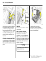
Pi cture no: 17048t.tif
To lock
Insert the key or em ergency key for
O pen&Start system 3 (see page 35) into
the opening above the lock on the inside of
the d oor a nd press until the lock audibly
enga ges. Then c lose the door. The
proced ure m ust b e repeated for ea ch door.
The d riv er’s door can also be locked from
outside using the lock. The unlock ed fuel
filler flap and tailgate/boot lid cannot be
locked.
Emergenc y operat ion of Op en&St art
system 3 ,
see page 35.
Open&S tart sy stem with electronic key 3
Pulling the button below the handle
unlocks and opens the luggage
compartment and doors w hen the
electronic k ey is d etec ted within the outer
reception range
– or –
Press button q on the radio remote control
of the electronic key , this unlocks the
lugg age compartment a nd the doors.
Picture no: 16969t.tif
To open
The lugg age compartment is opened b y
operating the button beneath the handle.
9 Warnin g
Do not drive with the tailgate open or
ajar, e.g. w hen transporting bulky
objects, sinc e toxic exhaust gas could
penetra te the interior.
Fitting of accessories on the tailgate will
increa se its weight. I f it becomes too heav y,
the tailgate w ill then not stay open.
44
Keys, Doors, Windows, TwinTop
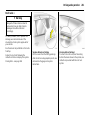
Vauxhall alarm system
3
monitors
z the doors, luggage compartment,
bonnet,
z the passenger compartment,
z vehicle tilt, e.g. if it is raised,
z the ignition.
9 Warnin g
Pi cture no: 17049t.tif
Pict ure no: 17042t.tif
To close
Close lugg age com partment using the
handle on the inside of the tailga te.
To lock
Close doors, luggage compartment and
tank flap.
Do not operate the button beneath the
handle when closing. Otherw ise the
luggage compartment will once again be
unlock ed.
Radio rem ote control with mec hanical key
Press button p on radio remote control.
Open&S tart sy stem with electronic key 3
Press button p of the electronic key radio
remote control or touc h sensor in ha nd le of
one of the front doors. The electronic key
must b e recognised in the external
reception area. It is advisable for the driver
to keep the electronic k ey on his person.
Do not use the system if there are people
in the vehicle! The doors cannot b e
unlocked from the inside.
Keys, Doors, Windows, TwinTo p
Pi cture no: 17043t.tif
To act ivat e
Radio remote control with mechanical key
All doors, wind ow s, the sun roof 3 and the
bonnet must be closed. Within 15 seconds
of locking, press button p on the radio
rem ote control again.
If the ignition was switched on, the driver’s
door must be opened and closed once so
that the Vauxhall alarm sy stem can be
switched on.
Pict ure no: 17044t.tif
Open&S tart sy stem with electronic key 3
All doors, w indows and bonnet must be
closed. The electronic k ey must b e in the
outer reception rang e of the vehicle. No
more than 15 seconds after locking, touch
the sensor in the handle of the driver’ s or
front passenger door again
– or –
press button p of the electronic key’s
remote control ag ain.
If the ignition wa s switched on, the driver’s
door must b e opened a nd closed once so
that the Vauxhall alarm system can be
switched on.
45
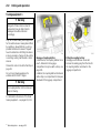
Picture no: 17050t.tif
Act ivat ion without monitoring of
pa ssenger comp artment a nd vehicle ti lt
To activa te e.g. if anim als are left in the
vehicle.
1. Close tailgate and b onnet.
2. Press b utton b in the roof console.
The LED in b utton m flashes
(max. 10 seconds), see nex t page.
3. Close doors.
6
46
Keys, Doors, Windows, TwinTop
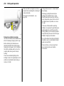
4. Switch on Va ux ha ll alarm system. LED
illuminates. After approx. 10 seconds the
system is activated, without monitoring
of the passenger compartment or vehicle
tilt. LED flashes until system is switched
off.
For Astra TwinTop, pa ssenger
compartment monitoring is deactivated if
the roof is open to p revent false alarms.
Light emit ting d iode (LED)
During the first 10 seconds of Vaux hall
alarm system activation:
z LED on
=
Test, activa tion delay,
z LED flashes
quick ly
=
Door, luggage
compartment or
bonnet open, or
sy stem fault.
Pict ure no: 17051t.tif
After the first 10 second s of Vauxhall alarm
sy stem activation:
z LED flashes slow ly =
System
activated ,
z LED on after
=
approx . 1 second
Deactivation
function.
If a system fa ult occ urs, contact a
work shop.
Picture no: 16968t.tif
To deact ivat e
Rad io remote control with m echanical key
Press button q on radio remote control
– or –
S witc h on ig nition.
Keys, Doors, Windows, TwinTo p
47
In the event of a fault in the radio remote
control or the Open&Start system , open the
vehicle as described on page 42.
If the alarm is trigg ered when the driver’ s
door is opened, dea ctiv ate the Vaux hall
alarm system by switching on the ignition.
Note
Changes to the vehicle interior, such a s the
use of seat covers, could impair the
function of passenger comp artment
monitoring.
Pi cture no: 17032t.tif
O pen&Start system with electronic k ey 3
Pulling a handle or the button below the
tailgate handle unlocks the v ehicle and
disables the Vaux hall alarm system w hen
the electronic key is detected within the
outer reception range
– or –
Press button q of the elec tronic key’ s
rem ote control.
Alarm
While the Vauxhall alarm system is
switched on the alarm can be triggered:
z an acoustic sig nal (horn) and
z a v isual signal (hazard w arning lights).
The number and duration of the alarms are
legally established.
The alarm can be silenc ed b y pressing a
button of the radio remote control or by
switching on the ig nition. The Vauxhall
alarm system is d eactivated at the same
tim e.
Picture no: 17052t.tif
Child safety locks
3
9 Warnin g
Use the child safety lock whenever
child ren are occupying the rear seats.
Disregard may lea d to injuries or
endanger life. Vehicle passengers should
be informed accordingly.
Using key or screwdriver, turn knob on rear
door lock from the vertical position: d oor
cannot be opened from inside.
48
Keys, Doors, Windows, TwinTop
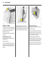
Pi cture no: 16978t.tif
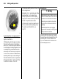
Exterio r mirrors
Manual adjustment with handles in the
front doors or electric 3 with switch in
driver’s door console.
Adj ust exterior mi rrors manuall y
Swiv el ha nd le in mirror base on front d oors.
The m irror g la ss swivels in the sam e
direc tion as the activation of the handle.
Pict ure no: 18437t.tif
Adjust ext eri or mirrors electric ally 3
Ad just with the four-way switch in driv er’s
door: press mirror switch to left or right:
four-way switch w ork s on corresponding
mirror.
The mirror glass swiv els in the same
direction as the ac tiv ation of the four-way
switch.
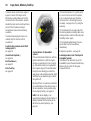
Asp heri cal ext eri or mirror 3
The aspherical m irror gla ss reduces the
blind sp ot. The curvature makes ob jects
appea r sm aller, so it is more difficult to
estimate the distance from following
vehicles.
Picture no: 18438t.tif
Sw ing in exter ior mirr or
Manual: The exterior mirrors can be swung
in by pressing on the outside of the
housing.
Electrically 3: Press n and b oth mirrors will
swing in.
Press button n again - both exterior
mirrors swiv el to the driving position.
If an electrical retracted mirror is ex tended
ma nually, pressing button n will cause the
mirror to move all the way forwa rd . The
other m irror will be swivelled to the driv ing
position. If b utton n is pressed ag ain, both
mirrors will be electrically retra cted. Press
aga in: both mirrors swivel to the driv ing
position.
Fold mirrors b ack into driving position
before moving away.
Keys, Doors, Windows, TwinTo p
Pi cture no: 17120t.tif
For the safety of pedestrians, the exterior
mirrors will swing out of their normal
mounting p osition if they are bumped with
sufficient force. Reposition the m irror by
apply ing slight pressure to the mirror
housing.
Pict ure no: 16977t.tif
In terior mirror
To adjust, swivel mirror housing.
To reduce d azzle from following v ehicles at
night, swiv el lever on the und ersid e of the
mirror housing.
49
Picture no: 17121t.tif
Autom atic anti-da zzle interior mi rror 3
Dazz le at night is automatically reduced.
With the ignition off, the mirror does not
dim.
50
Keys, Doors, Windows, TwinTop
Electric windo ws
3
9 Warning
Ta ke c are when operating the electric
wind ows 3 and the sun roof 3. Risk of
injury, particularly to children. Vehicle
passengers should be informed
according ly .
If there are children on the rea r seat,
switch on the child safety system 3 for
the electric windows.
Keep a close watch on the wind ow s a nd
sun roof when closing them. Ensure that
nothing becomes trapped in them as
they m ov e.
The electric wind ow s ca n be used
z with ig nition on,
z within 5 minutes of switching ignition
off 3 ,
z within 5 minutes of switc hing ignition key
to position 1.
Stand-by after switching on the ignition
ends when the driver’s door is opened .
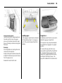
Pict ure no: 17134t.tif
Operated via two or four 3 switches in the
driver’s door handle. The front sw itc hes are
for the driver and front passenger doors.
The rear switches 3 are for the rear d oors.
Ad ditional switches are loca ted in the front
passenger door and rear doors 3.
For increm ental opera tion, briefly pull or
press the switch. For a utomatic opening or
closing, pull or press the sw itch longer. Pull
or press the switch again to stop the
movem ent.
Picture no: 17135t.tif
Sa fet y functi on
If the window glass encounters resistance
abov e the middle of the window d uring
automatic c losing, it is imm ediately
stopped and the w indow opened again.
In the event of difficulty due to frost or the
like, press the relev ant window switch
sev eral times until the window is closed.
Keys, Doors, Windows, TwinTo p
Pi cture no: 17136t.tif
Pict ure no: 17976t.tif
Chil d safety syst em for rear wi nd ows 3
Switch z between the rear switches in the
driver’s door ha nd le
Central swi tch for electric window s,
Ast ra TwinTop
Button $ or " in the roof console.
z Forward (red field visible): Rear door
switches non-operational.
Press button $: all windows are closed.
z Rearward (green field visible): Rear door
switches operational.
Press button ": all windows are opened .
51
Picture no: 17046t.tif
O perating windows from outside 3
Depending on the equipment level of the
vehicle 3, the wind ow s of v ehicles with
electric windows in all doors 3 c an be
opened or closed from outside using the
radio remote control.
Rad io remote control with m echanical key
Hold button q or p on the radio remote
control dep ressed until all windows ha ve
opened or com pletely closed.
52
Keys, Doors, Windows, TwinTop
Overloa d
If the windows are repeatedly operated at
short intervals, the power supply is b riefly
cut off.
Fault
If a utomatic opening and closing of the
windows is not possible, activate the
window electronics as follows:
The system is protected by fuses in the fuse
box – see page 262.
1. Close doors.
2. Switch on ignition.
3. Window com pletely open.
4. Close the window and hold the button
depressed at least 5 seconds.
5. Repeat for ea ch window.
Pi cture no: 17034t.tif
O pen&Start system with electronic k ey 3
Hold d own button q of radio rem ote
control to op en. To close, hold down
button p or touch sensor in door ha ndle
for long er. The electronic key must be
recognised within the ex ternal rec eption
range. It is advisable for the driv er to keep
the electronic key on his person.
Stand-by after switching on the ignition
ends when the driver’s door is opened .
Keys, Doors, Windows, TwinTo p
53
Not e
C lose the sun visors before slid ing the roof
lining.
Pi cture no: 17140t.tif
Pano ramic windscreen 3
O pen t he roof l ining
Turn the handle to the right and move the
roof lining rearward to a suitable position.
Pict ure no: 17141t.tif
Close the roof lining
Move the roof lining forward to a suitable
position. When mov ed all the way forward,
the roof lining engages in p osition.
54
Keys, Doors, Windows, TwinTop
To raise:
When the roof is closed, press button ü.
The roof is tilted in the rear.
To op en:
Press button ü again from the tilted
position. The roof opens to its stop .
To close:
Press button d.
For reasons of safety, the roof closes from
its open position to approx . 20 cm. H old
button d depressed to close c om pletely.
Pi cture no: 17138t.tif
Sun roof 3
O perated via rock er switches in the roof
console when the ignition is switched on.
For incremental operation, briefly p ress the
button. For a utoma tic opening or closing,
press the b utton longer.
Picture no: 17139t.tif
Sunb lind
Used to reduce sun penetration into the
interior when the sun roof is closed.
The sunblind opens when the sun roof
opens.
To open:
Press button G. The sunblind opens to its
stop.
To close:
Press button H.
For reasons of safety , the blind closes from
its open p osition to approx. 20 cm. Hold
button d depressed to close completely.
Keys, Doors, Windows, TwinTo p
55
Note
z If the top of the roof is wet, raise roof,
allow water to run off and then op en
roof.
Overloa d
If the system is ov erloaded, the power
supply is automa tic ally cut off for a short
tim e.
Fault
If the sun roof and sunblind do not opera te
properly , ac tiv ate electronics as follows:
z When using a roof rack, check the
clearance of the sun roof to av oid
damage.
The system is protected by fuses in the fuse
box – see page 262.
2. Close the sun roof and hold button d
depressed at least 10 seconds.
1. Switch on ignition.
3. Close sunb lind and hold button H
depressed at least 10 seconds.
56
Keys, Doors, Windows, TwinTop
TwinTop
With TwinTop, a convertible hardtop, Astra
unites the benefits of a coupe with those of
a convertible.
9 Warning
Ta ke c are when operating the
conv ertible hardtop. Risk of injury.
Monitor the action zone above, to the
side and to the rear of the vehicle during
roof operation. Make sure that nothing
could become pinched .
Make sure no one is in the action zone of
the roof or boot lid during roof operation.
Risk of injury.
Check the am ount heig ht, length and
width of available space before
op erating the roof, e.g. in a garage,
parking garage or when a bicy cle rac k is
fitted.
Pictu re no: 18024T.tif
Picture no: 17962t.tif
Operat ing the convertib le hardtop
Stand-by with ignition key in lock from
position 1, or for Open&Start-System 3
switch on ignition.
To open the roof
There must be no ob jects in front of the
rear w indow or in the p ivot a rea of the roof
and b oot lid .
Requirem ents:
Hold button > in the roof console
depressed until the roof is completely open
and the boot lid is closed.
z Vehicle is stationary or driving no m ore
than 20 mph (30 km /h).
Vehicle passengers should be informed
according ly .
z Luggage compartment blind is closed
and engaged - see above and pa ge 82.
Before leaving the vehicle, remove the
ig nition key in order to prev ent
unauthorised operation of the w indows
and sun roof.
z Boot lid is closed.
If any of the requirements a re not fulfilled,
a warning b uz zer sounds when the switch is
actuated a nd the roof does not open or
close.
An acoustic signal sounds at the end of the
opening proc edure.
O pen the door windows slightly b efore
opening the roof. If button > is pressed
aga in after the acoustic signal sounds, the
door windows will close.
Keys, Doors, Windows, TwinTo p
Pi cture no: 17970t.tif
With the vehicle stopped , the roof can b e
opened using the radio remote c ontrol 3.
Unlock the vehicle. Press button q again
and keep pressed until the roof has opened
fully and the boot lid has closed.
During operation with the remote control,
the d oor w indows are opened comp letely .
Pict ure no: 17963t.tif
To close t he roof
There m ust be no objects in the pivot area
of the roof and boot lid.
Hold button < in the roof console
depressed until the roof and boot lid are
completely closed.
An acoustic signal sound s at the end of the
closing procedure.
Open the door windows slightly before
closing the roof. If button < is pressed
again after the acoustic signal sounds, the
door wind ow s w ill close.
57
Picture no: 17971t.tif
With the vehicle stopped, the roof ca n be
closed using the ra dio remote control 3.
Lock the v ehicle. Press button p ag ain and
keep pressed until the roof and b oot lid
have closed c om pletely.
6
58
Keys, Doors, Windows, TwinTop
Ind icator a nd war ni ng buzzers
z Ind icator buzzer upon com pleted
op ening or closing of the convertible
hardtop.
z Ind icator buzzer upon completed ra ising
or lowering of the electric luggag e
com partment load ing aid.
z Gong tone if the boot lid is not closed
during roof opera tion.
z Gong tone if the boot lid is not fully
op ening during operation of the lugga ge
com partment load ing aid.
z Gong tone during roof operation if
vehicle speed exceeds 20 m ph (30 k m/h).
z Gong tone when v ehicle speed exc eeds
20 mph (30 km/h) if the roof is not fully
op en or closed.
z Three gong tones during roof or loa ding
aid operation if the lug gage
com partment b lind is not attached.
z Three gong tones d uring roof operation
if outside temperature is below –20 °C,
vehicle battery voltage is too low or the
system is overloaded.
z C ontinuous warning buzzer during roof
opera tion if the anti-roll b ars 3 have
been triggered.
z C ontinuous warning buzzer starting one
minute b efore the end of the 9-minute
stand-by time with the roof in an
intermediate position.
z C ontinuous warning buzzer starting one
minute b efore the end of the 9-minute
stand-by time with the loa ding aid in a
raised position.
z C ontinuous wa rning buz zer when closing
the boot lid if the lowering process of the
electric load aid is not complete or was
interrupted.
Not e
z Do not op en the lugg age com partment
until the acoustic signal indicating the
end of the roof opening or closing
procedure has sounded.
z The luggage compa rtm ent blind must
always be closed d uring roof opera tion.
z There m ust be no one a t the covers
behind the rear head restraints.
z There m ust be no objec ts in the pivot
area or the roof or on the covers behind
the rear head restra ints.
z The roof can only be opera ted a t
temperatures above –20 °C. If the
temperature is below this limit, a gong
will sound three times when roof
operation is requested.
z Frequent opera tion of the roof with the
engine off discharges the battery .
Keys, Doors, Windows, TwinTo p
z The roof can be held in an intermediate
position for 9 minutes to fac ilitate
cleaning of roof spa ces. This is d one by
diseng aging the a ctuation switch. O ne
minute before the end of this p eriod, a
continuous buzzer sounds as a w arning
that the hold period is a lm ost over and
the roof could start to m ove.
Fault
The automatic drive of the roof is only
op erational if the roof is in the proper open
or closed position.
z Activ ating the roof on uneven ground
can lead to malfunc tions and dam age.
z The boot lid is completely closed
Check if:
z The lugga ge c om partment b lind is
eng aged in the closed p osition
z O utside temp erature is abov e – 20 °C
z There is sufficient battery voltage
z There is a system ov erload
If the automatic driv e is not opera tional,
two persons are required to manua lly c lose
the roof. See the accomp any ing
instructions for Astra TwinTop. We
recommend that you seek professional
assista nce.
59
Roll over protecti on system
To optimise safety in the event of a
rollover, the Astra TwinTop is equipped
with reinforced windscreen fram e and antiroll bars behind the rea r sat head
restraints. The anti-roll bars are fix ed or
deployable depending on vehicle v ariant.
60
Keys, Doors, Windows, TwinTop
Pi cture no: 17975t.tif
Fixed anti-roll ba rs
are secured to the vehic le body work.
Pict ure no: 17974t.tif
Deployab le anti-roll bars 3
are located between the rear head
restra ints and the boot lid in such a way
that they are out of sight. In the event of a
rollover, hea d-on collision or side impa ct,
the anti-roll bars deploy upwards within
millisecond s. The convertible roof m ust not
be operated if the anti-roll bars hav e been
deployed. A continuous warning will sound
if the sw itch is actuated . The airbag control
indica tor v illuminates if the anti-roll b ars
ha ve b een deploy ed.
Manua l retra ction of the a nti-roll bars - see
page 104.
Further inform ation, see page 106.
Picture no: 17973t.tif
Luggag e c ompart ment
The roof ca n only be op ened if the load in
the lugg age compartment does not
exceed the height of the lugg age
compa rtm ent blind or protrude sideways.
The load height mark ed in the fig ure must
not be ex ceeded . The lugga ge
compa rtm ent blind m ust be flat; objects
below it must not press it upwards.
O therwise the roof and loa d may be
dam aged .
Electrically op erated loading aid for the
luggage compa rtm ent - see pag e 82.
Luggage compartment blind - see
pag e 82.
Keys, Doors, Windows, TwinTo p
Blockage of boot lid on closure 3
To a void da mage to the open roof, boot lid
or load, the boot lid ca n only be closed if
the electric load aid is in the lower end
position, see pa ge 82.
61
Wind d eflect or 3
With the wind d eflector installed
turbulence, draughts and noise in the
passenger compartment are reduced when
the roof is open.
The rear seats cannot be occupied when
the wind deflector is in place.
Do not place any ob jects on the wind
deflector.
Pict ure no: 18457t.tif
Unb lock ing on fa ilure of electric drive
Push locking lever forward as shown in the
figure.
62
Keys, Doors, Windows, TwinTop
Pi cture no: 17964t.tif
With ty re repa ir set 3, the w ind d eflector is
folded down into a storage comp artm ent 3
in the luggage compartment b elow the
loading floor cover.
For the version with spare wheel 3, the
wind deflector is folded away in the
luggage compartment
Pict ure no: 17965t.tif
Fitting
Ta ke the wind deflector from the lugg age
compartment.
Exp and the collapsed wind deflector as
illustrated.
Picture no: 17966t.tif
J oin tog ether the unfolded ends of the wind
deflector: press in the pin at the slider,
guide the hinge over the pin and release
the slider so that the pin eng ages in the
hinge.
Keys, Doors, Windows, TwinTo p
Pi cture no: 17967t.tif
Insert the guid e clips of the wind deflector
in the seat belt recesses between the rear
head restraints.
Pict ure no: 17968t.tif
Pull the tog gle of the rig ht a nd left locking
pin and turn to loc k. S traig hten out the
wind deflector, turn the toggle back and
engage the lock ing pin in the recess in the
side trim.
63
Picture no: 17969t.tif
The wind deflector can be folded back
when not in use.
If the wind deflector is folded a nd the rea r
seats are unocc upied, the wind deflector
can remain mounted in the vehic le when
the roof is closed.
Removing
Remove in reverse order, wind deflector is
completely fold ed d ow n in the luggage
compa rtm ent:
– for tyre repair k it 3 in the com partment
below the loading floor cover,
– for version with sp are wheel 3, place in
the lugg age compartment.
The wind deflector must never protrude
upwards or sidew ays from the luggag e
compa rtm ent, see marked loading height,
see page 60, Fig ure 17973 T.
64
Seats, Interior
Seats, Interior
Front sea ts .. .... ..... .... ..... .... ..... .... .... ..... .
Head restraints .... .... ..... .... ..... .... .... ..... .
Armrest 3 at driver’ s seat ..... .... .... ..... .
Armrest 3 in the rea r backrest . .... ..... .
Ex tending the lugg age compartment,
Hatch .... .... .... ..... .... ..... .... ..... .... .... ..... .
Ex tending the lugg age compartment,
Estate .... .... .... ..... .... ..... .... ..... .... .... ..... .
Ex tending the lugg age compartment,
Astra TwinTop ... .... ..... .... ..... .... .... ..... .
Fold ing down the front passenger
seat 3 .... .... .... ..... .... ..... .... ..... .... .... ..... .
Lug gage compartment cover .. .... ..... .
Safety net 3, Esta te. ..... .... ..... .... .... ..... .
Lug gage compartment grille 3, Va n.
Rails and hooks in the luggage
compartment 3, Estate . ..... .... .... ..... .
FlexO rganizer 3, Estate ... ..... .... .... ..... .
Lashing eyes 3 .... .... ..... .... ..... .... .... ..... .
Ca rg o box 3 .... ..... .... ..... .... ..... .... .... ..... .
Lug gage compartment blind ,
Astra TwinTop ... .... ..... .... ..... .... .... ..... .
Ea sy Load .... .... ..... .... ..... .... ..... .... .... ..... .
Notes on loading the vehic le .... .... ..... .
Three-stage safety sy stem.... .... .... ..... .
Three-point seat belts .. .... ..... .... .... ..... .
Belt tensioners. ..... .... ..... .... ..... .... .... ..... .
64
68
70
70
71
72
75
75
76
78
79
80
80
81
81
82
82
84
85
85
86
Using the belts .... ..... .... ..... .... .... ..... .... ..
Child restraint sy stem 3 ... .... .... ..... .... ..
Mounting brack ets 3 for IS OFIX child
restraint systems ... .... ..... .... .... ..... .... ..
Vauxhall Full Size airbag sy stem . .... ..
Rollover protec tion system 3 .. ..... .... ..
Cigarette lighter 3... .... ..... .... .... ..... .... ..
Ac cessory socket 3 . .... ..... .... .... ..... .... ..
Ashtray 3 ... ..... .... ..... .... ..... .... .... ..... .... ..
Foldaway tables 3 .. .... ..... .... .... ..... .... ..
Stowage compartments .. .... .... ..... .... ..
Sun visors, glov e comp artment .... .... ..
88
90
91
92
104
107
107
108
110
110
111
Picture no: 16970t.tif
Front seats
9 Warnin g
Never a djust seats while driving as they
could move uncontrollably.
Ad just seat longitudi nally
To adjust, pull the handle on the front seat,
slide the seat a nd relea se the handle.
9 Warnin g
Important: Do not sit nearer tha n 10
inches (25 cm) from the steering wheel, to
permit safe airbag d eploym ent.
Seats, Interior
Pi cture no: 16971t.tif
Pict ure no: 16973t.tif
Adj usti ng the back rest
To adjust, turn side handwheel on the seat
while releasing the loa d on the ba ckrest.
Adjusting t he seat height 3
To adjust, op erate lever on the outsid e of
the seat.
Move back rest to suit seating p osition.
Pump action on lever
up :
seat higher
down:
seat lower
65
Picture no: 16974t.tif
Ad just ing the sea t angle 3
To adjust, pull the lever on the front of the
seat, adjust the angle and release the
lever.
The seat should engage perceptibly.
Adjust the inclination b y distributing b od y
weight.
66
Seats, Interior
The seat bac k can only be tipped forwards
from an upright position.
When the backrest is folded forw ard, do
not activate the handw heel for ba ckrest
adjustment.
Panoramic windscreen 3: to fold the seats
forward, push the head restraints down
and c lose the sun visors.
Pi cture no: 16972t.tif
Adj usti ng the lumba r sup port 3
To a djust, turn sid e hand wheel on b ackrest
while reliev ing the load on the backrest.
Adjust lumb ar support to suit personal
req uirements.
Pict ure no: 16975t.tif
Fold the seat back rest forw ards 3
To fold forwards, ra ise the release lever
and fold the b ackrest forwards. Lower the
relea se lev er and the back rest engages in
the forward-fold ed position 3. Slide seat
forwards 3 .
To straighten the seat, slide back and it
engages in its original position 3 . Raise
relea se lever 3, straighten seat back, lower
relea se lev er, seat back engages.
For seat without memory function 3:
engage seat in d esired position.
Seats, Interior
67
The seat back rests m ust not be tilted too
far ba ck (recom mended max imum tilting
angle approx. 25°).
9 Warnin g
Failure to observe the descriptions could
lead to injuries which could be fatal.
Vehic le pa ssengers should be informed
accordingly before starting off.
Pi cture no: 17959t.tif
Pict ure no: 17350t.tif
Adj usti ng the thigh support 3 on the
sports seats 3
To adjust, press the button on the front of
the adjustment padd ing and slide the thigh
sup port.
Seat positi on
Ad just driver’s seat such that with the
driver sitting upright the steering wheel is
held in the area of its upper spokes with the
driver’s arm s slightly bent.
Adjust thigh support to suit personal
req uirements.
Push passenger sea t as far back as
possible.
68
Seats, Interior
Pi cture no: 16976t.tif
Head restraints
Pict ure no: 18019t.tif
Picture no: 17983t.tif
Adj usti ng the front head restraint s a nd
rear outb oard head restrai nt s 3
To adjust, press button on side and adjust
height.
Adjusting t he rear, cent re head
restra int 3
To adjust, pull the head restraint up or
press the catch to release. Then push the
head restraint down.
Ad just ing the rear head restraint s 3,
Astra TwinTop
To adjust, pull the head restraint up or
press the two catches to relea se. Then push
the head restraint down.
To fold down the backrests (see page 71)
or im prov e visibility when the rea r seats a re
not occupied, remov e the head restraints
or push them all the way down.
To fold down the ba ckrest (see page 71) or
improve v isibility when the centre rear seat
is not occupied , rem ov e the head restraint
or push it all the way down.
To improve visibility when the rear seats
are not occupied, push the head restraints
all the way down.
If the seats are occ upied, set height
according to body size.
If the seat is occupied, set height according
to body size.
If the seats are oc cup ied, set height
acc ording to body size.
Do not place any ob jects on the cover
behind the hea d restraints or b etween the
hea d restraints a nd the anti-roll bars 3.
Seats, Interior
Pi cture no: 17055t.tif
Pict ure no: 17011t.tif
69
Picture no: 17056t.tif
Head restrai nt position
The midd le of the head restraint should be
at eye lev el. I f this is not possible for
extremely tall persons, set to highest
position, and set to lowest position for
small persons.
Activ e head restra ints 3
In the event of a rear-end impact, the
active head restraints tilt forw ards slightly.
The head is more effectively supported by
the head restraint and the d ang er of
whip la sh in the neck area is reduced.
Remov ing the head restraint s
Press and release the two catches. Pull and
remove the hea d restraint.
9 Warning
Ac tiv e hea d restra ints are identified by the
lettering AC TIVE on the head restra int
guid e sleeves.
Not e
O nly approved objects or com ponents
should be a tta ched to the head restraint
of the unoccupied front p assenger seat.
Failure to ob serve the descriptions can
lead to injuries which could be fatal.
Vehicle passengers should be informed
according ly before moving a way.
To fold down the backrests 3 (see
pag e 71), push the rear head restraints
all the way down or remov e.
70
Seats, Interior
Pi cture no: 17058t.tif
Armrest 3 at driver’s seat
Push raised armrest back ward aga inst
resista nce and fold down.
The a rm rest can be moved to different
positions in stag es by lifting it.
Stowage comp artm ent in armrest, see
page 110.
Armrest
Pict ure no: 17060t.tif
Picture no: 17982t.tif
3 in the rear backrest
Fold d own the armrest, pulling the strap
ob liq uely d ow n (45°).
Astra TwinTop
Pull the armrest by the strap , pivot it down
and position on the sit with the flat side up.
When the centre rea r seat is in use or the
rear back rests are folded, fold the armrest
up .
The armrest is held in place on the backrest
with a retaining strap. To fully rem ov e the
armrest, disengage the brac ket a t the
reta ining strap.
A fla p located behind the armrest
fa cilitates transport of long, narrow
ob jects – see pag e 71.
A flap loca ted b ehind the arm rest
facilitates transport of long, narrow
objects – see page 75.
Seats, Interior
Pi cture no: 17061t.tif
Extending the luggage
compartment, Hatch
Folding t he ba ckrest
Pushing rea r head restraints all the way
down or remove – see page 69.
Slide front seat forward slightly .
Disengage the b ackrest (single or split 3)
using the pushbutton and fold it down onto
the seat cushion.
Return front seat to desired position.
Pict ure no: 17062t.tif
71
Picture no: 17063t.tif
Fold down centre ba ckrest 3
Push head restraint all the way d ow n – see
page 68.
Restoring b ackrest to a n up right p osit ion
Guide the seat belt through the side
brack et to protect against damage.
Disenga ge ba ckrest using handle and fold
onto sea t cushion.
Restore the backrest to an upright position
and a ud ib ly eng age.
Folding down the centre seat bac krest
makes it possible to loa d long er objects.
The outer seats can still be used for
oc cup ants.
The three-point seat b elt for the c entre rear
seat ca n only be pulled from its inertia reel
if the backrest is properly enga ged.
9 Warning
The load must not obstruct the operation
of the pedals, the handbrake or the g ears
or restrict the driver’s freedom of
movement. Do not p la ce loose objects in
the interior.
Not es on load ing
see page 84.
72
Seats, Interior
Pi cture no: 17064t.tif
Extending the luggage
compartment, Estate
Fold the bac krest onto the sea t cushion
Push the rear head restraints all the wa y
down or remove – see page 69. Detach the
hooks of the luggage compartment cover
from the head restraints – see page 77.
Slide front seat forward slightly .
Disengage the b ackrest (single or split)
using the pushbutton and fold it down onto
the seat cushion.
Return front seat to desired position.
Pict ure no: 17065t.tif
Raise the seat cushion a nd fold t he
back rest
Pull the strap on the seat c ushion and lift
the back rest forwa rd s (single or split).
Detach the hooks of the lugg age
compartment cov er from the head
restra ints – see pa ge 77.
Picture no: 17066t.tif
Remove the outer rear hea d restraints.
Push the centre head restra int a ll the way
down – see page 69.
S tow the removed head restraints in the
cav ity below the raised seat cushions.
Seats, Interior
73
Folding the centre seat backrest m akes it
possible to load longer objects. The outer
seats can still be used for occupants.
9 Warnin g
The loa d m ust not obstruct the opera tion
of the peda ls, the ha ndb rake or the gears
or restric t the driver’s freed om of
movement. Do not place loose objects in
the interior.
Pi cture no: 17067t.tif
Disengage the b ackrest (single or split)
using the pushbutton, fold it forward and
enga ge.
Pict ure no: 17062t.tif
Fold down centre ba ckrest 3
Push head restraint all the way d ow n – see
page 68.
Disenga ge ba ckrest using handle and fold
onto sea t cushion. If the seat cushion is
ra ised, fold it forward until it eng ages.
74
Seats, Interior
The three-point seat b elt for the c entre rear
seat ca n only be pulled from its inertia reel
if the backrest is properly enga ged.
Sa fet y net 3,
see page 78.
Not es on load ing,
see page 84.
Pi cture no: 17068t.tif
Restoring the ba ckrests or sea t
cushions 3 to their ori ginal p osit ion
Guide the seat b elt throug h the side
bracket to protec t against damage.
To restore the backrest to an upright
position, fold up, pressing the button on
the bac krest. Aud ibly engag e the bac krest
in an upright position.
Pict ure no: 17069t.tif
Raised seat cushions : Insert and adjust
head restraints in backrests – see
pages 5, 69. Fold back seat cushions,
making sure the belt b uck les are properly
positioned.
Attac h the hooks of the luggage
compartment cover to the head restraints –
see p age 77.
Seats, Interior
Pi cture no: 18020t.tif
Pict ure no: 17984t.tif
75
Picture no: 17076t.tif
Extending the luggage
compartment, Astra TwinTop
Cover behind arm rest can be locked from
lugg age compartment 3: turn handle 90°:
Folding down th e front passenger
seat 3
Loading a rea between rea r sea ts
Pull out the armrest b y the strap.
Locked
Unlock ed
The armrest is held in place on the b ackrest
with a retaining strap. To fully remov e the
armrest, disengage the brack et at the
retaining strap.
Push front passenger seat head restra int
all the way down or remov e – see
pag es 5, 69.
Notes on loading
see p age 84.
Pull the handle and fold down the cover.
9 Warning
The load m ust not obstruct the operation
of the pedals, the handbrak e or the gea rs
or restrict the driver’s freedom of
movem ent. Do not place loose ob jects in
the interior.
=
=
Handle horiz ontal
Handle vertic al
Push front passenger seat back.
Fold front p assenger seat forward b y
raising release lever.
Ra ise front p assenger seat ba ckrest
Raise release lever and enga ge pa ssenger
seat back a udib ly .
76
Seats, Interior
To close
Press handle on luggage comp artm ent
cover rea rw ards; the cover automatically
eng ages in its end position.
Do not place any heavy or sharp-edged
objects on the cover.
Pi cture no: 17077t.tif
Luggage compartment cover
Hat ch
To rem ov e, unhook the retaining strap s
from the ta ilg ate.
Pull cover from the side guides.
Fit in reverse order.
Pict ure no: 17078t.tif
Estat e
To op en
Press handle on lug gage compartment
cover d ow n. The cover automatically
unrolls.
Seats, Interior
77
Fitting
Insert the lug gage compartment cover in
the recess on the left, press the release
lever on the right side upward, insert the
cover in the recess on the right, engage
and p ress the lev er down.
Attach the hooks on the head restraints see Fig. 17079 T.
Pi cture no: 17079t.tif
To cover the ga p betw een the luggage
compartment cover and the rear
back rests, there is a c ov er on the cartridge.
Attach the two hooks of the cover to the
head restraint guid e rods. If the safety net
is mounted, run the hooks throug h the net
mesh.
Pict ure no: 17080t.tif
Removing
Open the luggage compa rtm ent c ov er and
detach the hooks from the head restraints.
Move release lev er on right side of lug gage
compartment cov er upwa rd . Lift rig ht
cover a nd remove from brac kets.
78
Seats, Interior
Pi cture no: 17081t.tif
Safety net 3, Estate
The safety net can b e mounted behind the
rea r seats or, if the rear seat backrests are
folded and the seat cushions ra ised,
behind the front seats.
Passeng ers m ust not be carried behind the
safety net.
Fitting behi nd the rear sea ts
Remove the lugg age com partment cover see left column.
Unroll the safety net.
There are two brackets in the roof fram e.
Hook the net rods into the b ra ckets on one
side a nd then the other. Slide forward to
enga ge.
Pict ure no: 17082t.tif
Ad just stra p length on safety net by
attaching the up per hook to the ey e of the
strap, see illustration 17085 T, and attach
to eyes in the right and left of the floor.
Picture no: 17083t.tif
Fitti ng behind front seats
Raise the rea r seat cushions, see page 72.
Unroll the safety net.
There are two brackets in the roof fra me
abov e the front seats. H ook the net rod s
into the brack ets on one side and then the
other. Slide forwa rd to engage.
Adjust strap length on safety net by
attaching the upper hook to the eye of the
strap, see illustration 17085 T, and attach
to eyes in the right and left of the floor.
Remove the outer rear head restra ints and
fold the backrests forward, see pag e 72.
Seats, Interior
Pi cture no: 17085t.tif
Remov ing
Deta ch the safety net belt straps by tipping
up the length adjuster.
Unhook the safety net rods from the
brackets in the roof frame. Roll up the net
and sec ure with a strap.
Pict ure no: 18440t.tif
Luggage compartment grille 3,
Van
To tra nsport long objects, p art of the
lugg age compartment g rille behind the
passenger seat c an be opened :
Release passenger seat back and fold
forward.
Press brac ket d ow n and fold grille section
up .
Lock grille in open position.
Picture no: 18441t.tif
79
To close the grille section from the open
position, press bracket down, fold down
grille and lock.
C heck that the closed grille is prop erly
locked.
80
Seats, Interior
Pi cture no: 17086t.tif
Rails and hooks in the luggage
compartment 3, Estate
The side wa lls of the luggage c om partment
house two rails. Insert the hooks in the
desired position in the ra ils: insert the hook
in the up per groove on the rail and p ress in
the lower groove.
Pull off the hook to rem ov e.
Pict ure no: 17087t.tif
FlexOrganizer 3, Estate
Flexible sy stem for dividing the luggage
compartment or securing load s in an
Estate.
The system c onsists of
z Adapters
z Variable partition net
z Mesh pock ets for the side walls
z Hooks in the lugga ge c om partment
Components a re mounted in the two guide
ra ils in the side walls of the lugga ge
compartment by means of adapters or
hooks.
Picture no: 17088t.tif
Varia ble part ition net
Insert an a dapter in each rail: Fold up
handle plate, insert adapter in up per and
lower groov e of rails, m ov e to d esired
position. To loc k the a dapter, swiv el the
handle plate up. Compress the rod s of the
partition net slightly and insert in
corresponding openings of the ad apter.
The longer rod must be inserted in the
upper adapter.
Seats, Interior
Pi cture no: 17089t.tif
Hooks a nd mesh pocket
Insert the hooks in the desired p osition in
the rails: insert the hook in the upper
groove on the rail and press in the lower
groove. The mesh p oc ket can be hung from
the hooks.
Remov ing
Press the partition net rods together and
rem ov e from the adap ters.
Adapter: fold op en the reta iner, release the
adap ter from the lower groove and remov e
from the upp er groove.
Release the hook s from the rails.
Pict ure no: 17090t.tif
Lash ing eyes
3
in the luggage compartment are intended
for fixing lashing straps 3 or a lugga ge
net 3. They secure transp ort items from
slipping.
81
Picture no: 17092t.tif
Cargo box 3
Foldable b ox under the floor cov er used to
divid e the lug gage compartment.
The cargo box may only be load ed w hen
the backrests are engaged in an upright
position.
To remove the cargo b ox floor cover,
remove first the right half then the left half.
For models with towing equipment, first
release the coupling ball bar fix ing strap
and thread this through the eye – see
pag e 235. Installation in the rev erse order.
82
Seats, Interior
Pi cture no: 18024t.tif
Luggage compartment blind,
Astra Twin Top
To open:
Disengage the luggag e com partment
blind from the recess on the right a nd left.
Rolls up automatically.
To close:
Grasp the handle, pull the blind towards
the rear of the vehicle and enga ge in the
recess on the right and left.
Do not place any objects on the blind.
There must be no objects outside of or on
top of the lugg age com partment b lind
when the roof is open or in the process of
opening.
The roof can only be operated with the
luggage compartment blind enga ged in
the recess.
Pict ure no: 17978t.tif
Easy Load
(Electronically operated loading
aid for the lu ggage compartment
of the Astra TwinTop)
The loading aid makes it possible to
comfortab ly load the luggage
compartment when the roof is open. The
press of a button will raise the roof folded
up in the luggage compa rtm ent 25 cm.
This enlarges the load op ening of the
lugg age compartment.
z O pen the boot lid.
z Unhook the lugga ge compartment b lind
and a ttac h it to the rear window frame.
Picture no: 17977t.tif
z Briefly press button ,: The folded roof is
raised. The roof remains in this end
position for approx. 9 minutes.
Seats, Interior
9 Warning
Take care when operating the loading
aid. Risk of injury.
Mak e sure tha t nothing could be pinched.
Mak e sure no one is in the action zone
during opera tion. R isk of injury.
This is esp ecially important for c hildren.
Inform passengers acc ordingly.
Pi cture no: 17973t.tif
z Load lugga ge c om partment a t most to
marked load heig ht, otherwise the roof
and load could be dam aged.
z Suspend the lugga ge c om partment
blind from the rear window frame, and
engage in recesses on right and left. The
lugga ge c om partment b lind must b e
flat; objects underneath it must not p ush
it up wards.
z Briefly press button ,: The folded roof is
lowered.
z Close the boot lid only after the
confirmation signa l has sounded.
Otherwise the roof could be damaged.
Note
z Do not place objects on or nea r the
luggage compa rtm ent blind.
z The folded roof can only be lowered
when the blind is closed. Otherwise, a
warning buzzer will sound three tim es.
z Movement can only be stopped by
pressing button ,. Holding the button
depressed will cha nge the direction of
movement.
z A confirmation signal sounds in the
upper and lower end positions.
z O nly close the boot lid once the
confirm ation signal has sounded to
indicate tha t the loading aid is in its
lower end position.
83
z If the loading aid is not in its lower end
position when the boot lid is closed, a
warning tone sounds or the boot lid is
blocked mecha nically 3, see p age 61.
z Do not touch m ov ing parts.
z One minute before the end of the hold
time for the raised loading aid , a
warning b uzz er will sound to remind you
to lower the roof.
z The loading aid is only op erable when
the vehicle is unlocked.
84
Seats, Interior
z Estate: mount the safety net 3 when
transp orting objects in the luggage
compa rtm ent – see p age 78.
z Estate: close the luggage compartment
cover so the rear window does not reflect
the ob jects.
Pi cture no: 17093t.tif
Notes on loading the vehicle
z Heav y objec ts in the lug gage
com partment should be placed against
the enga ged rear seat backrests 3 or, if
the rear seat backrests are folded down,
against the front sea t backrests. If
ob jects are to be stacked, the heav ier
ob jects should be placed at the bottom.
Unsec ured objec ts in the lug gage
com partment w ould be thrown forward
with great force in the event of heavy
braking, for example.
z Secure objects with lashing straps 3
atta ched to lashing ey es – see p age 81.
If heavy loads slip when the vehicle is
braked heavily or driven around a bend,
the hand ling of the v ehicle ma y change.
z Astra TwinTop: Do not p la ce any objects
on the cover of the deployable anti-roll
bars 3, b ehind the rear head restraints
or in the luggage compa rtm ent outside
of, on or next to the luggage
compartment cover.
z If the backrests are not folded down
when transporting objects in the
luggage compa rtm ent, they must be
eng aged in their upright position 3 see
pages 71, 74.
z Do not place any objec ts in the
deploy ment area of the airb ags and
deploy able anti-roll bars 3 as this poses
a risk of injury should the system s be
trig gered.
z Do not a llow the load to protrude ab ov e
the upp er edge of the rear seat
back rests, or above the upper ed ge of
the front seat b ackrests if the rear seat
back rests 3 are folded down.
z Do not drive with lugga ge compa rtm ent
open when tra nsporting bulky objects,
for exam ple, since toxic exhaust fumes
could penetra te the interior.
z Astra TwinTop: Note the ma ximum
loading heig ht when the roof is open.
See page 82, Fig. 17973 T.
z The warning triangle 3 a nd first-aid k it
(cushion) 3 m ust alway s be freely
accessible.
z Do not place any objects in front of the
rea r window or on the instrument pa nel.
They are reflected in the glass, obstruct
the driver’s view and will be thrown
through the vehicle, for insta nce in the
event of heavy b ra king.
z The load m ust not obstruct the operation
of the p edals, the handbrake or the
gears or restrict the driver’s freed om of
movement. Do not place loose objects in
the interior.
z Weights, payload and roof loa d – see
page 325.
z Driv ing with a roof load see
pages 198, 200, 231, inc reases the
sensitivity of the vehic le to cross-winds
and has a detrimental effect on vehic le
ha nd ling ow ing to the vehicle’s higher
centre of gravity.
9 Warnin g
Failure to observe these descriptions can
lead to injuries which ma y be fatal.
Vehic le pa ssengers should be informed
accordingly.
Seats, Interior
Three-stage safety system
Com prising:
z Three-point seat belts.
z Belt tensioners at the front seats.
z Airbag sy stems for driver, front sea t
passenger and rear outboard seats 3.
On Astra TwinTop 3, roll-over bar
behind rea r seats.
The three stages are activated in sequence
depending on the sev erity of the accident:
z The automatic seat belt locking d evices
prevent the belt strap from b eing pulled
out and thus ensure that the vehicle
occ upa nts are retained in their seats.
z The front seat belts are pulled down at
the belt buckles. This mea ns the b elts fit
snugly, the occupants are d ecelerated
early with the vehic le and the body
load ing is reduced .
z In the event of a severe accid ent, the
airb ag systems and deployable anti-roll
bars 3 also dep loy , forming safety
cushions for the occ upa nts. The front
airb ags a re inflated in tw o stages based
on the severity of the collision.
85
9 Warning
The airb ag systems and a nti-roll bars 3
serve to supplement the three-point seat
belts a nd belt tensioners. The seat belts
must therefore always be worn.
Disregard of these instructions could lead
to injuries or endanger life. Vehicle
passengers should be informed
accordingly.
Read the instructions supplied with the
child restraint system !
Picture no: 16981t.tif
Three-point seat belts
The vehicle is equipped with three-point
seat belts with automatic retrac tors and
locking d evices, allowing freedom of body
mov ement although the spring tensioned
belts always ensure a snug fit.
For information on correct seating
position – see pages 67, 88, 94.
The belts are loc ked during heavy
acc eleration or deceleration of the vehicle.
86
Seats, Interior
9 Warning
Alwa ys wea r your seat belt, and that
means a lso in urban traffic a nd when you
are a rear sea t passeng er. I t can save
your life!
Pregnant women m ust alwa ys wear a
seat belt – see page 88.
In the event of an accident, persons not
wearing seat belts endanger their fellow
occupants and themselv es.
Control indicator X 3 for the seat belt – see
page 114.
Seat b elts are only intended for one person.
They are not suitable for any one under
12 yea rs of age or under 150 cm tall.
For children up to 12 yea rs of ag e, w e
recom mend the Vaux hall child restraint
system – see page 90.
Belt force lim iters
on the front seats reduce the b od y load
due to damped release of the belt on a
collision. This means that the occupants
move forward under control.
Testing the b el ts
Check all parts of the b elt system
periodically for d amage and function.
Replace dam aged components. After an
accident, have the belts and triggered belt
tensioners replaced by a workshop.
Do not p erform any alterations on the
belts, their a nchorages, the automatic
retractors or the belt buckles.
Make sure that belts are not damaged or
tra pped by sharp-ed ged ob jects.
Picture no: 17104t.tif
Belt tensioners
The front seat belts are fitted with belt
tensioners. The seat belts are pulled down
at the buckles on a front or rear impact
abov e a certain sev erity. This tightens the
belts.
Act uation of belt tensioners
is indicated by illumination of control
indicator v, see nex t column.
If the belt tensioners are triggered, they
must be replac ed b y a work shop.
Im portant information – see pag e 87.
Seats, Interior
9 Warning
Hav e the cause of the fa ult eliminated
immediately.
The system’s integ ra ted self-diagnostics
allow s faults to be quickly remedied.
Pi cture no: 17105t.tif
Cont rol indica tor v for belt t ensioners
The function of the belt tensioners is
monitored electronically together with the
airbag sy stems and the d eployab le antiroll bars 3. Their operational readiness is
indicated by control indicator v in the
instrument panel. When the ignition is
switched on, the control indica tor
illuminates for approx. 4 second s. If it
does not illuminate, does not go out after
4 seconds or illum inates whilst driving,
there is a fault in the belt tensioner or and
airbag sy stems or in the deployable antiroll bars 3, see p age 98. The sy stems may
fail to trigger in the event of an a ccident.
Dep loy ment of the belt tensioners is
indicated by continuous illumination of v.
Imp or tant
z Accessories and other objects not
specifically approved for your vehicle
type must not be affixed or placed within
the action zone of the b elt tensioners
(near the belt buckles) as this c ould
result in injury if the belt tensioners are
triggered.
z Do not mak e any modifications to the
components of the belt tensioners, as
this will render the v ehicle unroadw orthy.
9 Warning
Incorrect handling (e.g. rem ov al or fitting
of belts or b elt buckles) c an trig ger the
belt tensioners w ith risk of injury.
87
z The belt tensioner and airbag sy stem
control electronics can be found in the
centre console area. In order to av oid
malfunctions, do not store mag netic
objects in this a rea.
z When using the rear sea ts, ensure that
the front belt com ponents a re not
damaged by shoes or other objects.
Avoid dirt getting into the belt wind ers.
z We recom mend that you have the front
seats removed by a w orkshop.
z The belt tensioners trigger once only,
ind ic ated b y illumination of control
ind ic ator v. Belt tensioners when
trig gered must be replaced by a
workshop.
z When disposing of the vehicle, the sa fety
instructions given for this must be
observed . Ta ke the vehicle to a recycling
company for disposal.
88
Seats, Interior
Pi cture no: 17106t.tif
Using the belts
Fitting seat bel ts
Pull the belt out of the retractor and guide
it across the body , making certain that it is
not twisted.
Insert the la tch plate into the buckle. The
front sea t b ackrest must not be tilted back
too far or the seat belt will not op erate
properly . The recommended angle of
inclina tion is 25° . Mak e sure that the lap
belt is not twisted and that it fits snugly
across the body. Tension the belt
frequently while d riv ing by tugging the
diagonal pa rt of the belt.
Pict ure no: 17107t.tif
9 Warning
O n pregna nt women in particular, the lap
belt must be positioned a s low as
possible across the pelvis so as not to put
too much pressure on the abdomen.
Bulk y clothing prevents the belt from fitting
prop erly. The belt must not rest against
ha rd or fragile objects in the pockets of
your clothing (e.g. ballpoint pens, keys,
spectacles) because these could cause
injury. Do not place any objec ts (e.g.
ha ndb ags, mobile phones) b etween the
belt and your body.
Picture no: 17108t.tif
Height adjustm ent 3
Height adjustm ent of the upper deflection
point of the front belts:
1. Pull b elt out slig htly.
2. Press d own button on adjuster slide.
3. Move adjuster slide up or down.
4. Allow sliding ad juster to a ud ib ly latch.
Do not adjust height while driving .
Seats, Interior
89
Three- point seat b el ts on rear outer seats
When not in use, pa ss seat b elts through
side holders 3 as shown in Fig. 17063 T on
pag e 71.
Three- point seat belt of cent re rear seat 3
The belt ca n only be pulled from the inertia
reel when the bac krests a re upright and
properly enga ged – see page 71.
Pi cture no: 16981t.tif
Adjust height such that the belt p asses
over the wearer’s shoulder and rests
against the shoulder. It must not pass over
the neck or upper arm.
Pict ure no: 17109t.tif
Rem oving t he b el t
To remove the belt, d epress the red
pushbutton on the buckle; the b elt will
retract automatically.
Three- point seat belts of rear seats in
Astra TwinTop
In order to prevent the flutter noise caused
by the belts when the roof and wind ow s are
open, the seat belts can be secured behind
the armrest when the rear seats are not
occupied.
90
Seats, Interior
Child restraint system 3
When a c hild restraint system is used ,
follow the instructions for use and
installation.
Perm issib le options for fitt ing a chil d safety seat1 )
Weight and
age class 2)
The c ountry in which y ou a re travelling
may not perm it the use of child restraint
systems on certain seats. Alw ays comply
with the local or na tional regulations.
Group 0:
up to 10 k g
or approx.
10 months
Selecting the right system
Your child should travel fa cing backwa rd s
in the c ar for as long as possible. A child
has a very w eak cervical spinal colum n and
in the event of an accident is less likely to
suffer injury in a rearwa rd -fac ing, semilying position than if seated upright.
Group 0+:
up to 13 k g
or approx.
2 years
9 Warning
Nev er carry child restraint sy stems on
your lap, risk of fatal injury.
Group I:
9 t o18 kg
or approx.
8 months to
4 years
O n front passenger seat
On out er r ear seat s
On centre rear seat3 )
B 1, +
U, +
U
B 2, +
U, +
U
X
U
U
Group II :
15 to 25 kg
or approx.
3 to 7 y ears
Group II I:
22 to 36 kg
or approx.
6 to 12 y ears
1)
2)
3)
For rea son s of safety, we recomm end tha t the ch ild safety sea t b e insta lled on
on e of the ou ter rea r sea ts .
We recom mend th e u se of each system until the child rea ch es th e u pp er w eig ht limit.
Not on Ast ra TwinTop.
Seats, Interior
B 1 = Lim ited, only with seat occupancy
recognition and Vauxhall child
restraint sy stem with transponders.
If the c hild restra int system is being
secured using a three-point seat
belt, move seat height adjustm ent 3
to uppermost position. Move front
passenger sea t as far back as
possible and move front passeng er
seat belt anchorage point to low est
position.
B 2 = Lim ited, only with seat occupancy
recognition and Vauxhall child
restraint sy stem with transponders.
If the c hild restra int system is being
secured using a three-point seat
belt, move seat height adjustm ent 3
to uppermost position. Move front
passenger sea t as far back as
possible so that v ehicle safety belt
runs from anchora ge point towards
the front.
U = Universal suitab ility in conjunction
with three-p oint seat belt.
+
= Vehicle sea t with ISO FI X fix ings
available. When using ISO FI X, only
ISO FI X child restra int system s
approved for the v ehicle may b e
used.
X = No child restraint system permitted
in this weight class.
91
Note
z C hildren under 12 years or under 150 cm
tall should only travel in an appropriate
child safety seat.
z When transporting children, use the child
restraint systems suitable for the child’s
weight.
z Ensure correct installation of child
restraint system, see the instructions
enclosed with the system.
z The covers of the Vauxhall child restraint
system can be wiped clean.
z Do not stic k anything on the child
restraint sy stems a nd do not cover them
with any other materia ls.
z O nly allow the c hild to enter and exit on
the side of the vehicle facing aw ay from
the road .
z A child restraint system whic h has been
sub jected to stress in an a ccident must
be rep la ced.
z Secure or remove child restra int systems
carried in the v ehicle when not in use.
Picture no: 17091t.tif
Mounting brackets 3 for ISOFIX
child restraint systems
The brackets located between the backrest
and seat cushion are used for mounting
IS OFIX child restraint sy stems.
Plea se follow the instructions
acc om panying the I SO FIX child restraint
system.
O nly ISO FIX child restraint sy stems
app rov ed for the vehicle may be used.
92
Seats, Interior
Pi cture no: 17009t.tif
Vauxhall Full Size airbag system
The Vauxhall Full Size airbag system
consists of several separate sy stems.
Front airb ag system
The front airbag system will be triggered in
the event of a serious ac cident involving a
frontal impact and forms safety cushions
for the driver and front passenger. The
forward movement of the driver and front
passenger is checked and the risk of
injuries to the upper body a nd head
thereby substantially reduced.
Pict ure no: 17110t.tif
Side airb ag system 3
The sid e airbag is triggered in the event of
a side-on c ollision to form a safety cushion
for the driver or front passenger in the
respective door area. This substantially
reduces the risk of injury to the upp er body
and pelv is.
Picture no: 17351t.tif
C ur tain ai rbag syst em 3
The curtain a irba g system triggers in case
of a side-on collision and provid es a safety
barrier in the hea d area on the respective
side of the vehic le. This reduces the risk of
injury to the hea d considerab ly in case of a
side-on collision.
Seats, Interior
93
Exception:
Passenger sea t with seat occupancy
recognition system 3 . The seat occupancy
recognition system deactiva tes the front
and sid e airbags on the pa ssenger side 3 if
the front passenger seat is unoccupied or a
Vauxhall child restraint system with
transponders 3 ha s been fitted to the front
passenger seat. S eat occupa ncy
recognition, see pag e 99. Vauxhall child
restraint sy stem with transponders 3 – see
pag e 90.
Pi cture no: 17111t.tif
Pict ure no: 17112t.tif
Vauxhall Full Size airbag system
z seat occ upa ncy rec og nition 3,
Front airb ag
The front airbag system is identified by the
word AI RBAG on the steering wheel and
above the glov e c om partment.
z the control indicator for Va ux ha ll child
restraint systems y with transponders 3
in the instrum ent panel.
The front airbag system comprises:
z an airbag with inflator in the steering
wheel and a second one in the
instrum ent panel,
z control electronics w ith im pact sensors,
z control indicator for airbag systems v in
instrum ent panel,
The front airb ag system will be trigg ered :
z depending on the severity of the
accident,
z depending on the type of impact,
z within the range shown in the illustration,
z indep endent of side airbag 3 and
curtain airbag system 3.
Examples of events triggering the front
airbag sy stem:
z Impact against a non-y ielding obstacle:
the front airbags are trigg ered at low
vehicle speed.
z Impact aga inst a y ielding obsta cle (such
as another vehicle): the front airbags are
only trigg ered at a hig her vehicle speed .
94
Seats, Interior
Pi cture no: 17009t.tif
When triggered, the front airb ags inflate in
millisecond s to form a safety cushion for the
driver and front passenger. The forward
movement of the front seat occupants is
check ed, thereby substantially reducing the
risk of injury to the upper body and head.
No im pairment of view will occur, because
the a irb ags inflate and deflate so quickly
that it is often not ev en noticed in an
accident.
Pict ure no: 17350t.tif
Picture no: 16981t.tif
9 Warning
9 Warnin g
The front airbag sy stem provides
optimum p rotection when the seat,
back rest a nd head restraint are correctly
adjusted: Adjust the driver’s seat
according to the occupant’s height suc h
that with the driver sitting upright the
steering wheel is held in the a rea of its
upper sp ok es with the d riv er’s arms
slightly bent. The passenger seat should
be as far back as possible, with the
back rest upright – see pages 3, 67. Do
not place the head, b od y, hands or feet
on the c ov ers of the airbag sy stems.
Do not place any objects in the area in
which the airb ags inflate. Im portant
inform ation – see page 101.
The three-point seat belt must b e
correctly fitted – see pag e 88.
The front airbag sy stem will not be
triggered in the ev ent of
z the ignition is switched off
z minor frontal collisions
z accidents in which the vehicle overturns
z collisions involving a sid e or rear impac t
that is to say, if it w ould not be of benefit to
the oc cup ants.
Seats, Interior
95
9 Warning
Seat belts m ust therefore a lways be worn.
The front a irb ag system serv es to
supplement the three-point seat belts. If
you do not wea r your seat belt you risk
being seriously injured, or even thrown
from the vehic le, in the ev ent of an
accident.
In the event of an ac cident the belt helps
to keep you in the correct seating
position, so tha t the front airbag system
can provid e you with effective p rotection.
In addition, the front airb ag sy stem will not
be triggered for the front passenger in
versions with seat occupa ncy rec og nition 3
if
z the front p assenger seat is unoccupied,
z there is a prop erly fitted Va ux ha ll child
restraint system with transponders 3 .
Seat oc cup ancy recognition – see
page 99. Vauxhall child restraint system
with transponders 3 – see page 90.
Pict ure no: 17113t.tif
Side airb ag 3
The side a irb ag system is identified by the
word AIRBAG on the outb oa rd sides of the
front seat backrests.
The side a irb ag system c om prises:
z an airbag with infla tor in the back of the
driver’s and front passenger seat
respectively ,
z the control electronics,
z the side impact sensors,
z control indicator for airb ag sy stems v in
instrument panel,
z seat occ upa ncy rec og nition 3,
z the control indicator for Va ux ha ll child
restraint systems y with transponders 3
in the instrum ent panel.
Picture no: 17114t.tif
The side airbag sy stem will be triggered:
z depending on the sev erity of the
accident,
z depending on the ty pe of im pact,
z within the range shown in the illustration
on the centre d oor pillar of the driver’s or
front passenger side,
z ind epend ently of the front airbag
sy stem.
Exception:
Passenger sea t with seat occupancy
recognition system 3 . The seat occupancy
recognition system deactiva tes the front
and sid e airbags on the pa ssenger side 3 if
the front passenger seat is unoccupied or a
Vauxhall child restraint system with
transponders 3 ha s been fitted to the front
passenger seat. S eat occupa ncy
recognition, see pag e 99. Vauxhall child
restraint sy stem with transponders 3 – see
pag e 90.
96
Seats, Interior
9 Warning
There must be no objects in the area in
which the airb ag inflates or in the a rea
between the seat backs and the vehicle
body . Do not place the hand s or arms on
the covers of the airba g systems.
Imp ortant information – see page 101.
The three-point sea t b elt must a lw ays be
correctly fitted – see page 88.
Pi cture no: 17110t.tif
When triggered, the side a irba g infla tes
within milliseconds to form a safety cushion
for the driver or front passeng er in the
respective door area. This substantially
red uces the risk of injury to the upper body
and pelvis in the event of a side-on
collision.
The side airba gs will not be triggered in the
event of
z the ig nition is sw itc hed off,
z fronta l collisions,
z accidents in which the v ehicle overturns,
z collisions involving a rear impac t,
z side-on collisions outside the pa ssenger
cell.
In ad dition, the side airb ag system 3 will
not be trig gered for the front p assenger in
versions with seat oc cup anc y recognition 3
if
z the front passeng er seat is unoccupied,
z there is a properly fitted Vauxhall child
restra int system with transponders 3.
Seat occupancy recognition – see
page 99. Vauxhall child restraint system
with transponders 3 – see page 90.
Seats, Interior
Pi cture no: 17115t.tif
Pict ure no: 17114t.tif
Curt ain airb ag 3
The c urtain airbag sy stem is identified by
the w ord AIRBAG on the roof pillar trim.
The curtain airbag system will be triggered:
The c urtain airbag sy stem comp rises:
z depending on the type of impact,
z an airbag with inflator in the roof frame
on the driver’ s and front pa ssenger sid e
respectively,
z the control elec tronics,
z the side im pact sensors,
z control indicator for airbag systems v in
instrum ent panel.
z depending on the severity of the
accident,
z within the ra ng e shown in the illustration
on the c entre door p illar of the d riv er’s or
front passenger side,
z together with the side airbag system 3,
z irrespectiv e of sea t occupancy
rec og nition 3,
z indep endently of the front airbag
system.
Picture no: 17351t.tif
97
When the curtain a irb ag is triggered it
inflates within milliseconds and provides a
safety barrier in the head area on the
respective side of the v ehicle. This red uces
the risk of injury to the head considera bly in
case of a side im pact.
98
Seats, Interior
9 Warning
9 Warnin g
There m ust be no objects in the area in
which the airbag inflates. Do not place
the hands or arms on the covers of the
airb ag systems. I mportant information –
see pa ge 101.
Have the c ause of the fault elim inated
immediately by a workshop.
The sy stem’s integrated self-diagnostics
allows faults to b e q uick ly rem edied.
The three-point seat belt m ust always be
correctly fitted – see page 88.
The curtain airbags will not be triggered in
the event of
z the ignition is switched off,
z frontal collisions,
z accidents in whic h the vehicle overturns,
z collisions involving a rear im pact,
z side-on collisions outsid e the passenger
cell.
Pict ure no: 17105t.tif
Control i nd icator v for airbag systems
The func tion of the airbag systems is
monitored electronica lly together with the
seat occupancy recognition 3 and belt
tensioner systems and the deployable a ntiroll b ars 3. Their operationa l readiness is
indica ted b y a control indicator v. When
the ignition is switched on, the control
indica tor illum ina tes for ap prox . 4 seconds.
If it does not illuminate, does not go out
after 4 seconds or illum inates whilst
driving, there is a fault in the airba g
sy stems, seat occupancy recognition 3 or
belt tensioner systems, or in the deployable
anti-roll bars 3 , see page 87. The systems
may fail to trigg er in the event of an
accident.
Deploym ent of the airba gs is indicated by
continuous illumination of v.
Seats, Interior
Seat oc cupancy recognition 3
The seat occupancy recognition system
deactivates the front and side airbags 3
for the front passenger if the front
passenger seat is not occ upied or a
Vauxhall child restraint sy stem with
transponders 3 is fitted on the front
passenger seat. The curtain airba g
system 3 rem ains activ ated.
The c ontrol indicator y for seat
occupancy recognition is located in the
instrument panel. If the control indicator y
illuminates for approx. 4 seconds w hen the
ignition is switched on, the vehicle is
equipp ed with seat occ upa ncy recognition,
see next page, Fig . 17117 T.
If a Vauxhall c hild restra int system with
transponders 3 is fitted, the control
indicator y illuminates perm anently after
the ig nition is switched on as soon as the
system has detected the child restraint
system. Only then may the child restraint
system with transponders 3 be used on the
passenger seat.
99
9 Warnin g
Only Vaux hall child restraint systems with
tra nsponders 3 can be fitted on the front
passeng er seats. Use of sy stems without
tra nsponders poses a risk of fatal injury.
Vauxhall child restraint systems with
transponders 3 can b e identified by a
sticker.
Pict ure no: 17116t.tif
Vehicles with seat occupancy recognition
are also identified by a sticker on the lower
panel of the front passenger seats – see
figure above.
Vauxhall c hild restraint system s w ith
tra nsponders 3 are automatically
detected if correctly fitted to the front
passenger seat. When this typ e of child
restra int system is in use on the front
passenger seat, the front and side a irb ag
sy stems for the front p assenger seat are
deactiv ated. The curtain airbag system
remains ac tiv ated. Pay attention to control
indica tor y for seat occupancy
recognition 3 see Fig . 17117 T.
Not e
O n the Astra TwinTop, there may be
interference in ra dio reception of c ertain
freq uencies in the m edium w aveb and
when the roof is op en and the front
passenger seat is unoccupied.
100
Seats, Interior
Cont rol indica tor y for Vauxha ll child
restraint syst em s with t ransponders 3
The p resence of a Vaux hall child restraint
system w ith transponders 3 is indicated
after the ignition has been switched on by
permanent illumination of the control
indicator y in the instrum ent panel, as
soon a s the seat occupancy recognition
system has detected the child restraint
system.
If the control indicator flashes when the
child restraint system with transponders 3
is c orrectly fitted, there is a fault with risk of
injury to the child. Fit child restraint system s
on the rear seat. Have the cause of the
fault elim inated by a workshop.
If no Vauxhall child restraint system w ith
transponders 3 is fitted, the control
indicator m ust not illum inate or flash as the
passenger airbag systems would not
deploy. Have the cause of the fault
elimina ted b y a work shop.
Pict ure no: 17117t.tif
If the control indicator does not come on
while driving, the front and sid e airba gs 3
for the p assenger are not d e-activated and
there is a risk of injury or death to the child.
Fit child restraint systems on the rea r seat.
Have the cause of the fault eliminated by a
work shop.
If the child restraint system is not correc tly
installed or the transp onder is faulty , the
control indicator flashes. Chec k for correct
installation of child restraint system . To
install the child restra int system with
tra nsponders 3, see the instructions
enclosed with the sy stem.
9 Warnin g
If the Vauxhall child restraint system with
tra nsponders 3 ha s b een fitted
according to the instructions, the control
ind ic ator for Vauxhall restraint systems
with tra nsponders must illumina te in the
instrument pa nel when the ignition is
switched on.
If the control indica tor does not come on
while driving, the airbag sy stems for the
passeng er are not de-ac tiv ated and
there is a risk of fatal injury. In this ca se,
fit child restraint system s on the rear seat.
Have the ca use of the fault eliminated by
a workshop .
Seats, Interior
Im portant
z Do not affix or p lace accessories or other
ob jects in the deployment area or the
airb ag systems or deployable anti-roll
bars 3 a s this could result in injuries if the
com ponents are triggered.
z Do not bond or use other material to
cover the steering wheel, dashboard,
front seat back rests and roof frame in
the area of the airbags and the seat
cushion of the passenger seat or the
covers of the deployable anti-roll bars 3.
z Do not p la ce a ny objects between the
airb ag systems/a nti-roll bar cov ers 3
and the occupants. Risk of injury .
z Use only a dry cloth or interior cleaner to
clean the steering wheel, instrument
panel, front seat back rests, roof frame
and sea t cushion of the front passeng er
seat. Do not use any aggressive cleaning
agents.
9 Warning
Nev er carry child restraint sy stems or
other objects on your lap - risk of fatal
injury.
z Use the hooks in the roof frame only to
hang up light articles of clothing or c oa t
hangers. Do not place any objects in the
pockets of the hanging items – risk of
injury.
z The control elec tronics of the airbag
system s, belt tensioners and deploy able
anti-roll bars 3 are located in the centre
console area . Do not store any mag netic
ob jects in the area as they could cause
malfunction.
z O nly protective covers whic h are
approved for y our v ehicle with side
airbag 3 ma y be fitted on the front
seats. When fitting the protective covers,
mak e sure that the airbag units on the
outboard sides of the front seat
back rests a re not covered.
z The airb ag systems are triggered
indep endently of each other based on
the sev erity of the accident and the ty pe
of im pact. The sid e airbag system 3 and
the curtain airba g system 3 are
triggered together.
z Astra TwinTop: The deployable anti-roll
bars 3 a re deployed together with the
front and sid e airba g systems 3
depending on the severity of the impact.
101
z Each a irb ag or deployable roll-ov er
bar 3 d eploys once only . Hav e a
workshop replace dep loy ed airbags
immediately.
z The speeds, directions of movement and
deformation properties of the vehic les,
and the p roperties of the obstacle
conc erned, determ ine the severity of the
accident and triggering of the airbags.
The degree of dama ge to y our vehicle
and the resulting repair costs alone are
not indica tiv e that the criteria for
trig gering of the airb ags were met.
z Do not make any m od ifica tions to
components of the airbag systems or the
anti-roll ba rs 3 as this would render the
vehicle unroad worthy.
9 Warnin g
The systems can b e triggered abrup tly
and cause injury if they are ha nd led
improperly.
z We recom mend ha ving the steering
wheel, the instrument panel, all panelling
parts, the door sea ls, the handles and
the seats removed by a workshop.
102
Seats, Interior
z When disposing of the vehicle, the safety
instruc tions given for this must be
ob served. Tak e the vehicle to a recycling
com pany for disposa l.
z Persons weighing less than 35 kg should
only tra vel on the rear seats. This does
not ap ply to children who are trav elling
in c hild restra int system s w ith
transponders 3.
z In vehicles with seat occupancy
recognition 3, do not plac e any heavy
ob jects on the front passenger seat
otherw ise the airba g systems for the
front p assenger sea t may be trigg ered in
the ev ent of an acc ident.
z In vehicles with seat occupancy
recognition 3, to prevent m alfunctions
do not use protective covers or sea t
cushions on the front passenger seat.
z In order to prev ent malfunctions when
using a Vaux hall child restraint sy stem
with transp onders 3 on the front
passenger seat, no objec ts (e.g. plastic
sheet, stick ers or heated mats) may be
placed under the child restraint system.
9 Warning
C hild restraint system s a s well as other
objec ts m ust nev er be carried on the lap
of passengers; risk of fatal injury. I f
carried in this way, child restraint sy stems
with transponders 3 in v ehicles with seat
occupancy recognition 3 could lead to
front passenger airbag sy stems not
being triggered in the event of an
accident.
Picture no: 17118t.tif
Use of child restra int systems 3 on t he
front p assenger seat in v ehic les w ith
ai rbag syst em s, but wi thout sea t
occup ancy recog nition 3
9 Warnin g
No child restraint system 3 may be
installed on front passenger seat. Danger
to life.
Versions with front passeng er airbag can
be identified by the word AI RBAG over the
glove compa rtm ent and the warning
sticker on the side of the instrument panel,
visible when the passenger door is open see Fig. 17118 A.
Seats, Interior
103
Vehicles with sea t occupancy recognition
are identified by a stick er on the low er
panel of the front passenger sea t – see
Fig. 17116 T.
Pi cture no: 17119t.tif
The side airbag system 3 is identified by
the word AI RBAG on the outboard sides of
the front seat b ackrests.
Seat occupancy recognition 3 – see
page 99.
Pict ure no: 17116t.tif
Use of chil d restraint syst em s 3 on front
passenger seat in v ehi cles w ith ai rbag
systems and seat occup ancy
rec ognition 3
9 Warning
O nly Vauxhall child restra int sy stems with
transp onders 3 can be fitted on the front
passenger seats. Use of systems without
transp onders pose a risk of fatal injury.
104
Seats, Interior
Rollover protection system
3
The Astra TwinTop is eq uipp ed w ith
rollover protection with reinforced
windscreen frame and anti-roll bars behind
the rear sea t head restraints. Depending
on the variant, the a nti-roll bars are either
fixed or deploy automatically in the event
of an imp act of a certain severity . The
subsequent desc ription only regards the
va riant w ith a utomatica lly deployed antiroll bars 3.
Pi cture no: 17117t.tif
Vehicles with seat oc cup anc y recog nition
can also be identified by c ontrol
indicator y in the instrum ent panel.
If control indicator y illumina tes for
approx. 4 seconds when the ignition is
switched on, the vehicle is eq uipp ed w ith
seat occupancy recognition see page 99.
The seat occupancy recognition system
detects Vaux hall child restraint sy stems
with transponders 3 and deactivates the
front and sid e airbag sy stems 3 for the
front passenger seat. The curtain airbag
system 3 rem ains activ ated. For sea t
occupancy recognition see pa ge 99.
Pict ure no: 17424t.tif
Vauxhall c hild restraint system s w ith
tra nsponders 3 can be identified by a
sticker on the child restraint system – see
figure.
Seats, Interior
Pi cture no: 17974t.tif
In the event of a rollover, the anti-roll bars
deploy upwards in a matter of
milliseconds. They also deploy tog ether
with the front and side airbag systems 3 ,
helping to optim ise occupant protection.
The system dep loy s whether the roof is
open or closed. Roof opera tion is not
possible if the a nti-roll bars are ex tended .
Pict ure no: 17105t.tif
Control i nd icator v for anti-roll bars
The deployable anti-roll b ars a re
monitored electronica lly together with the
belt tensioners and the airbag systems.
Their op erational readiness is indicated by
control indica tor v in the instrument panel.
When the ignition is switched on, the
control indicator illuminates for approx.
4 seconds. If it does not illuminate, does
not g o out a fter 4 seconds or illum inates
whilst driving, there is a fa ult in or
deploym ent of the anti-roll bars, b elt
tensioners and airb ag systems - see
page 87. The systems may fail to trigger in
the event of an ac cident.
Deploym ent of the anti-roll bars is
indica ted b y continuous illum ination of v.
105
Picture no: 17992t.tif
Extended a nt i-roll b ars
can b e retra cted (e.g. in order to close the
roof after a collision).
Press the lever between the rods of an antiroll bar to unlock the system . Push the antiroll bar a ll the way down until it engaged.
Fit the cov er.
Repeat the procedure on the other anti-roll
bar.
C ontrol indicator v, however, will rema in
illuminated and the a nti-roll bars will not
deploy in the event of another collision.
6
106
Seats, Interior
Hav e the cause of the fault eliminated
immediately by a workshop .
The roof cannot b e closed or opened if
the anti-roll bars are extended. The antiroll b ars m ust first be retracted.
Note
z Do not place any objects on the covers of
the anti-roll bars behind the hea d
restraints. They w ould be p ropelled
through the vehicle in an uncontrolled
fashion should the anti-roll bars deploy .
Such objects could also prevent the a ntiroll bars from extending.
If an attempt is mad e to operate the roof
while the a nti-roll bars are ex tended, a
continuous signal will sound as a
warning.
z Do not operate the roof while the antiroll bars are ex tended . Parts of the roof
could be dam aged during such
opera tion.
9 Warning
z Deploym ent of the a nti-roll bars is
ind ic ated b y illumination of control
ind ic ator v.
z Manually retracted anti-roll ba rs will not
deploy in the event of a collision.
z After deploy ment of the anti-roll b ar,
ha ve the system repaired by a w ork shop
immediately.
Seats, Interior
Pi cture no: 17094t.tif
Cigarette lighter 3
The c ig arette lighter is located under the
ashtray cover.
The cover opens when pressed at the point
indicated .
Pict ure no: 17095t.tif
Press in ciga rette lighter. Switches off
autom atic ally once the element is glowing.
Pull out lighter.
107
Picture no: 18023t.tif
Accessory socket
3
S om e vehicles have an ac cessory soc ket for
the connection of electrical accessories
instead of a cigarette lighter. Use of the
acc essory socket while the engine is not
running will discharge the battery.
6
108
Seats, Interior
Elec trica l accessories connected to the
socket must comply with the
electrom agnetic comp atibility
requirements laid down in DIN VDE 40 839,
otherwise vehicle malfunctions ma y occur.
If the tyre repair set is 3 is in opera tion, no
consumers ma y be connected to the
auxiliary socket.
Pi cture no: 17096t.tif
Estates hav e an a dditional accessory
soc ket 3 in the luggag e com partment.
Do not dama ge the sock ets by using
unsuitable plugs.
The m aximum power consum ption of
electrical accessories must not ex ceed
120 watts.
Do not connect any current-delivering
accessories, e.g. electrica l charging
devices or ba tteries.
Picture no: 17094t.tif
Ashtray 3
To be used only for ash and not for
comb ustible rubb ish.
9 Warnin g
Failure to observe these descriptions can
lead to injuries which ma y be fatal.
Vehic le pa ssengers should be informed
accordingly.
Ashtray, front
The cover op ens when pressed a t the point
indicated.
Seats, Interior
Pi cture no: 17097t.tif
To empty, grip both sid es of the ashtray
insert at the spots illustrated and pull
upwards.
Pict ure no: 17098t.tif
Rea r ashtray 3
In the rear centre console.
Pull out the ashtray by pushing on one of
the sides.
Picture no: 17099t.tif
109
To empty, open the ashtray, press the
spring (arrow) a nd pull the a shtray straight
out rea rw ards.
110
Seats, Interior
Foldaway tables 3
on the front seat ba ckrests.
O pen by pulling upward until it engag es.
Fold away by p ressing down p ast the
resista nce point.
Do not place any heavy ob jects on the
table.
Pict ure no: 17101t.tif
Stowage compartments
Glove comp artm ent
To op en, pull handle upwards.
The glove compartment shelf 3 can b e
removed: Disengage the shelf by pulling on
the front edge.
Refit the shelf b y sliding it into the side
guid e strips and engage it in the rear panel
by pushing.
The front of the open c ov er houses a pen
holder and a coin compartment.
Cooled glov e c om partment 3 – see
page 156.
Picture no: 17103t.tif
St owage comp artm ent in front arm rest 3
To open, press button and open upper part
of armrest.
Seats, Interior
Sun visors, glove com partment
Use the sun visor to protect from glare by
pulling it down and swivelling it to the
side 3.
The mirror covers in the sun visors a nd the
glove compartment should be closed whilst
driving.
On vehicles with panora mic windscreen 3,
close the sun visors before moving the roof
lining.
Pi cture no: 17102t.tif
Stow age com partm ent for glasses 3
O n driver’s side: fold down to open.
Do not store heav y objects in the stowag e
compartment.
111
112
In struments, Controls
Instruments, Controls
Pict ure no: 18444t.tif
Control indic ators
Control indicators .... ..... .... ..... .... .... ..... .
Instrument display ... ..... .... ..... .... .... ..... .
Information display . ..... .... ..... .... .... ..... .
Warning buzzers.. .... ..... .... ..... .... .... ..... .
Wind screen wiper .... ..... .... ..... .... .... ..... .
112
119
122
140
141
–
The control indica tors described here are
not p resent in all vehicles. The description
applies to all instrum ent versions.
The control indica tor colours mean:
z Red
Danger, important rem ind er,
z Y ellow
z Green
Warning , note, fault,
O n confirmation,
z Blue
O n confirmation.
0
Open&Sta rt system 3
Control indica tor illuminates or flashes
yellow.
If it flashes
System has not detected electronic key in
vehicle interior. The reasons for this m ay
be:
–
Picture no:
The electronic key is in the wrong
location in the vehicle interior (do not
put k ey in luggage compartment or
in front of information display), or
the electronic key is not in the vehicle
interior, or influence from an external
interference sourc e (radio masts,
interfering transmitters in the
vicinity).
or
Elec tronic key failure, for em ergency
op eration – see pag e 35.
If the battery in the electronic key needs
changing, I nSP3 appea rs in the service
display or, in vehicles w ith check control 3 ,
by an appropriate message in the
inform ation display - see pages 36, 120.
In struments, Controls
Lights
Fault in Open&S tart sy stem.
Loc k or unlock v ehicle using rem ote control
or emergency key if necessary – see
page 42, or attem pt to use the spare key.
I
Engine oil p ressure
Control indica tor illuminates red.
Em ergency operation – see page 43.
It illum ina tes when the ignition is switched
on a nd goes out shortly after the engine
starts.
If 0 illuminates, this can also mea n that
the steering wheel lock is still loc ked: move
steering w heel to and fro a little and press
Start/Stop button again.
Illum inates when the engine is running
Engine lub ric ation may be interrupted . This
may result in dam age to the engine and/or
lock ing of the drive wheels:
If 0 illuminates whilst driving a system
error has occurred that may eventually
lea d to a com plete failure.
1. Move out of the flow of traffic as quickly
as possible, without impeding other
vehicles.
If 0 illuminates or flashes: The Start/S top
button must b e held depressed somew hat
longer to switch off the ignition. It is
possible that the v ehicle will not start
during the next start attem pt.
2. Depress clutch.
If these flash continuously or if 0
illuminates, contact a workshop
immediately .
3. Move gearshift lev er to neutral, or with
Easy tronic 3 , place selector lever in N.
4. Sw itch off ignition.
113
9 Warnin g
When the eng ine is off, considerably
more force is needed to brake and steer.
Do not remove key until v ehicle has com e
to a standstill, otherw ise the steering
colum n lock could engage unexpectedly .
C ontact a workshop for a ssistance.
114
In struments, Controls
v
Airb ag system s 3 , belt tensioners 3,
depl oyabl e a nt i-roll b ars 3
C ontrol indicator illuminates red.
Illuminates when the eng ine is running
Fault in airbag system, belt tensioners or
roll-over protection, see pages 87, 98, 104.
v
R
Pi cture no: 18444t.tif
Brak e system , clut ch system
Control indicator illuminates or flashes red.
It illum ina tes a fter the ig nition is turned on,
when the hand brake is applied or if the
brake or clutch fluid lev el is too low. For
further information see pages 221, 302.
For vehicles w ith Easytronic 3, the control
indicator flashes for a few seconds when
the ig nition is turned off if the hand brak e
is not applied.
Picture no:
9 Warning
Lights when the handbrake is released:
stop vehicle immediately. C ontac t a
workshop for assista nce.
Electronic S tabil ity Prog ramm e
(ES P®P lu s ) 3
C ontrol indicator flashes or illuminates
yellow.
Flashing during driving
S ystem ac tiv ely engaged, see
pag es 208, 209.
Illuminates while driving
S ystem switched off or fault in system for
Electronic Stability Program, see p age 209.
X
Seat belt 3
C ontrol indicator illum inates or flashes red .
Lights w hen the ignition is turned on, until
the seat belt is fastened. After starting to
drive, the control indicator flashes.
Fasten seat belt, see pag e 88.
In struments, Controls
Q
Door open
Control indicator illum inates red.
It is illum inated w hen a door or the luggag e
compartment is open.
p
Alternat or
Control indicator illum inates red.
It illuminates when the ignition is switched
on and goes out shortly after the engine
starts.
Illuminates when the engine is running
Stop, switch off eng ine. Battery is not
charging. Cooling may be faulty. For diesel
engines, the effect of the brak e serv o may
be lost. Contact a w ork shop imm ediately.
W
Coola nt temperat ure
Control indicator illum inates red.
Illuminates when the engine is running
Stop a nd sw itch off engine. C oola nt
tem perature too high: Dang er of eng ine
dam age. Chec k coolant level
immediately – see pa ge 300.
115
A
j
It illum ina tes for a few seconds when the
ignition is switc hed on.
It illuminates if the foot brake is not
operated. The ind ic ator goes off as soon a s
the foot brake is operated. The engine can
only be started with the foot brake
operated, see page 182.
Engine electronics, t ransmission
elect ronics 3, im mobil iser, d iesel fuel
filter 3
Control indica tor illuminates or flashes
yellow.
Illum inates when the engine is running
Fault in eng ine or gearbox electronic
sy stem. Electronics hav e switched to
emergency running programm e fuel
consumption may be increased a nd the
vehicle’s driveab ility reduced, see
page 206. C ontact a workshop
immed iately.
Illum inated together with InS P4 in the
service display : Ha ve the diesel fuel filter
drained of wa ter – see p age 300.
Flashes when the ignition is on
Fault in the electronic im mobiliser sy stem;
the engine cannot be started – see
page 29.
Easytronic 3, star t eng ine
C ontrol indicator illuminates yellow .
I DS +
I nt era ctiv e Dri ving S ystem 3, Continuous
Dam ping Control (CDC ) 3 , S PO RT mode 3
C ontrol indicator illuminates yellow .
It illuminates for a few sec onds when the
ignition is switched on.
Illuminates while driving
Fault in sy stem. C ontac t a workshop
imm ediately.
IDS + - see pag e 176, CDC – see page 210,
S PO RT mode – see p age 210.
116
In struments, Controls
O
Turn signal lights
C ontrol indicator flashes green.
The corresp onding c ontrol indicator
flashes on the side of the direc tion
indicators selected.
Both control indic ators flash with the
hazard warning lights on.
Fast fla shing: failure of a direction
indicator light or associated fuse, failure of
direction indicator light on trailer 3.
S
Pi cture no: 18444t.tif
Eng ine oi l level 3
Control indicator illum inates yellow.
8
Picture no:
Exterior light s
Control indica tor illuminates green.
C ha nge bulbs, see page 269. Fuses, see
pag e 262.
Y
The engine oil level is c hecked1)
automatically.
It is illum ina ted when the exterior lights are
on – see page 143.
Fuel lev el
C ontrol indicator illuminates or flashes
yellow.
Illuminates when the engine is running
Engine oil level too low. C heck engine oil
lev el and top up engine oil if necessary, see
page 298.
r
Lights
Low fuel level, fuel gauge in reserv e a rea.
Pa rking distance sensor 3
Control indica tor illuminates y ellow.
Fault in system. Contact a work shop
immed iately.
Pa rk ing distance sensor, see page 214.
Flashing
Fuel supply exhausted, refuel immediately .
N ever let the tank run dry!
Erra tic fuel sup ply can c ause catalytic
converter to overheat, see pa ge 204.
Diesel engines: I f the tank is run dry, bleed
the fuel sy stem as desc rib ed on pag e 241.
1)
Not on Z 14 XEP or Z 20 LEH en gine. Sales
design atio n – see pa ge 310 .
In struments, Controls
>
Fog light s 3
Control indicator illum inates green.
It is illum ina ted when the fog lights are on –
see page 145.
C
Mai n bea m
Control indicator illum inates blue.
It is illuminated when main beam is on and
during headlight flash – see pa ge 11.
r
T
Wi nt er program me of autom atic
transmission 3 or Easyt ronic 3
Control indica tor illuminates in gear
display with Winter programm e engaged .
Further inform ation – see
pages 180, 186, 193.
1
SPORT mode of autom atic tra nsm ission 3
or Easytronic 3
Control indica tor illuminates in gear
display with Sport p rogram me engaged.
Fog tail light
Control indicator illum inates yellow.
Further inform ation – see
pages 179, 185, 192.
It is illum inated when the fog tail lig hts are
on – see pa ge 145.
y
Z
Exhaust emi ssion 3
C ontrol indicator illuminates or flashes
y ellow.
It illuminates w hen the ignition is switched
on and g oes out shortly after the engine
starts.
Illuminates when the eng ine is running
Fault in emission c ontrol system. The
permitted emissions may be ex ceeded.
C ontact a workshop immediately.
If it flashes when the engine is running
Fault which could lead to damag e to the
cataly tic conv erter, see pa ge 205. Contact
a work shop imm ediately.
Seat occup ancy r ecog ni tion 3
Control indica tor illuminates or flashes in
mileage display.
u
Lights
Sea t occupancy recognition has detected
a child restraint system with tra nsponders.
Airba g systems for the passenger are
deactiv ated, see page 99.
Illuminates while driving
Fault in anti-lock brake system, see
pag e 223.
Flashing : Fa ult in system or child seat with
tra nsponder not correctly fitted, see
page 99.
117
Anti -lock Bra ke Syst em (ABS ) 3
C ontrol indicator illuminates red.
118
In struments, Controls
B
Ad aptiv e Forwa rd Lighting 3 (AFL)
C ontrol indicator illuminates or flashes
yellow.
Lights
Fault in sy stem. C ontac t a workshop
imm ediately.
Flashing
S ystem converted to sym metrical dipped
beam.
AFL – see page 147.
!
Pi cture no: 18444t.tif
Preheat ing system 3, Diesel p articl e
filt er 3
Control indicator illum inates or flashes
yellow.
Lights
Preheating system active, switches on only
if outside tem perature is low.
Flashing
(on vehicles with diesel p artic le filter)
Diesel particle filters m ust be clea ned.
Continue driving and as soon as the road
and traffic conditions permit it, increase
speed to more than 25 m ph (40 km /h), at
which point diesel particle filter cleaning
will start. The control indicator goes off as
soon a s cleaning is complete. We
recom mend leaving the ignition switched
on during the cleaning .
Further information – see pa ge 207.
w
Picture no:
Defla tion detection syst em 3, tyre
pressure monit oring system 3
Control indica tor illuminates red
Ty re p ressure loss – see pag e 217.
Control indica tor illuminates y ellow
Fault in system, see pages 217, 218.
Contact a workshop for assistance.
m
C ruise cont rol 3
C ontrol indicator illuminates green.
It is illuminated w hen the system is on – see
pag e 212.
In struments, Controls
Pi cture no: 17021t.tif
Instrum ent display
O n some versions, the p ointer of the
tachometer, speedometer and fuel gauge
briefly moves to its end position when the
ignition is switched on.
Tachom eter
Indicates engine speed.
Warning zone: M aximum p ermissible
engine speed exceeded; danger to engine.
Speedometer
Speed d isplay .
Picture no:
119
Picture no: 17023t.tif
Fuel gauge
Pointer in left
zone or Y
illuminated
Pointer in left
zone or Y
flashing
= Reserve area
= Refuelling,
see pag e 202
N ever run the tank dry !
Diesel engines: I f the tank is run dry, bleed
the fuel sy stem as desc rib ed on pag e 241.
Because of the fuel remaining in the tank,
the amount of fuel required to fill the tank
ma y be less than the spec ified tank
cap acity.
120
In struments, Controls
Tim e d isplay 3
To adjust the time, setting knob in
instrument:
Press for approx . 2 seconds:
Hours flash
Press briefly
Set hours
Press for approx . 2 seconds
Minutes flash
Press briefly
Set minutes
Press for approx . 2 seconds
Clock is started .
Picture no: 17335t.tif.
O dometer displa y
Top line:
Trip odometer or clock displa y 3
To switch between the trip odometer and
the c lock display 3 , press reset knob
briefly , see prev ious page.
Trip odometer
Display of miles covered sinc e reset.
To reset, hold reset button down for
around one second with the ignition turned
on, see previous pag e.
If the clock display is activated, first switch
to trip odometer.
Bottom line:
Odometer
Records the m iles counted.
Picture no: 17008t.tif
Serv ice Display
I nS P
S ervice interval d isplay . Shows
distance remaining to nex t
service. Further notes, see
pag e 296.
I nS P2
Bulb blown 3, see page 269.
I nS P3
Battery voltage of radio remote
control or electronic key in
O pen&Start system low 3, see
pag es 31, 36.
I nS P4
Water in diesel fuel filter 3.
C ontact a workshop for
assistance.
O n vehicles with check control 3, a
message is shown on the info display
instead of I nSP2 and InSP3.
In struments, Controls
ESPoff
ESPon
121
For Easytronic 3, the display flashes for a
few seconds if A, M or R is selected when
the engine is running but the foot brake is
not depressed.
Electronic Stability Programm e 3
off, see page 208.
Electronic Stability Programm e 3
on, see page 208.
Pict ure no: 17022t.tif
Tr ansm issi on display 3
Display of gea r selected in automatic
tra nsmissions 3 or current gear or mode
for Easytronic 3:
P
Part position on automatic
transmission.
R
N
Rev erse gear.
Neutral.
A
M
Automa tic mode on Easytronic.
Manual mode on Easytronic.
D
Automa tic mode on autom atic
transmission.
1-4
Current gear on automatic
transmission.
1-5
Manual mode, current gear for
1-6 3 Easytronic.
122
In struments, Controls
12:01
17,0 °C
FM 3 90,6 MHz
REG
AS
RDS
TP
11:25 }
21 .5 °C
Timer
Pi cture no: 17336t.tif
Tripl e inform ation d isp lay
Display of time, outside tempera ture and
date/infotainm ent system (when it is on).
When the ignition is off, the time, date and
outside tem perature can be presented for
15 second s b y briefly pressing one of the
two buttons b elow the displa y.
F in the display indicates a fault. Hav e the
cause eliminated by a workshop.
19,5° 19:36
All values
Pict ure no: 17337t.tif
Board inform ation di sp lay 3
Display of time, outside temp erature a nd
date/infotainment sy stem (when it is on).
F in the displa y indicates a fa ult. Have the
cause elim inated by a workshop.
257.0
40
1
Ø
8
7.0
Ø 31.0
[ TP]
257miles
Information display
Board Computer
BC 2
Range
RDS
2
BC 1
miles
mph
gal
Lt r. /100km
Picture no: 17344t.tif
Grap hical i nfor mation d isplay 3,
C olour informat ion displa y 3
Display of time, outsid e tem perature, date/
infota inm ent system (when it is on) and
climate control sy stem 3 .
The graphical information d isplay presents
the information in monochrome. The colour
inform ation display presents the
inform ation in colour.
In struments, Controls
The ty pe of information and how it is
displayed depends on the equipment of
the v ehicle and the settings of the trip
computer 3, clima te control sy stem 3 a nd
infotainment sy stem 3 .
Some information appea rs in the display in
an abb reviated form.
Clim ate control system – see page 168.
Infotainm ent system – see infotainment
system instructions.
8:56
-5 ,5° C
07.04.2004
123
:
F in the display indicates a fault. Hav e the
cause eliminated by a workshop.
Slippery road
-2, 5°C
OK
Pict ure no: 17336t.tif
Outside temperature
A fall in temp erature is indicated
immed iately and a rise in temperature
after a tim e delay.
If outside temp erature d rops to 3 °C , the
sy mbol : illuminates in the triple
information display or the board
information display 3 as a wa rning for icy
road surfaces : rema ins illuminated until
temperatures reach a t least 5 °C .
Picture no: 17338t.tif
In v ehicles with graphical information
display 3 or colour information display 3,
a warning message appears the display as
a warning for icy road surfaces. There is no
message below -5 °C.
9 Warnin g
Caution: The road surface may already
be icy even though the d isplay indicates
a few deg rees ab ov e 0 °C .
124
In struments, Controls
8:56
5 ,5 °C
07.04.2004
Pi cture no: 17024t.tif
Triple info rmation display
Set d ate and ti me
Infotainm ent system off: p ress Ö and ;
below the display as follows:
Press Ö for ap prox . 2 seconds:
Day fla shes
;: Set day
Ö : Month fla shes
;: Set month
Ö : Year flashes
;: Set year
Ö : Hours flash
;: Set hours
Ö : Minutes flash
;: Set minutes
Ö : Clock is started.
Correcting time 3
Some RDS transmitters do not send a
correct time sig nal. If the incorrect time is
continually displa yed, switch off automa tic
tim e synchronisation 3 a nd set the tim e
manually - see nex t column.
The automatic setting is indicated by } in
the display.
Deactivating/ac tiv ating autom atic time
synchronisation: infotainment sy stem off,
press Ö and ; below the display:
Hold down Ö for a pprox. 2 sec., cloc k
display is now in setting m ode.
Press Ö twice (until year flashes).
Press Ö and hold down for approx.
3 seconds until } flashes in display 3
and " RDS TIME" a ppears (years fla sh
during this tim e).
Press ;; display shows:
RDS TIME 0 = O ff.
Press ;; display shows:
RDS TIME 1 = O n.
Press Ö three tim es.
In struments, Controls
11:25}
125
21.5 °C
Range
257miles
Pi cture no: 17337t.tif
Board information display 3,
Selecting functions
Functions and settings of some
equipm ent 3 can be accessed via the
board information disp lay.
This is used with the menus and buttons of
the I nfotainment System 3 or with the left
adjuster wheel 3 on the steering wheel.
The c orresponding m enu options are then
displayed in the next line of the display.
If warning messages from C heck control 3
are shown, the display is blocked for other
inform ation. Confirm the wa rning
message. If there are several warning
messages, confirm these in succession.
Picture no: S0013209.ti f
Selec tion wit h arrow k eys
Select the menu points using the buttons
on the Infota inm ent system.
OK button
Select mark ed p oint, confirm c om mand.
Picture no: 17014t.tif
Select using the l eft adjuster wheel 3 on
the steer ing wheel
Turn up
Prev ious menu point,
Turn down
N ext m enu point,
Press
S elec t marking, c onfirm com mands.
S ystem settings – see pa ge 131.
Trip comp uter – see pa ge 128.
126
In struments, Controls
The functions are displayed in the following
order:
11:25}
21.5 °C
System
Pi cture no: 17337t.tif
Board information display 3,
System settings
Press the Sett ings button of the
infotainment sy stem. M enu item Audio or
System will app ear.
Press left arrow key to access menu p oint
System . S elect menu point System. The
first function of the menu System is shown.
Some information appea rs in the display in
an abb reviated form.
z
z
z
z
z
z
z
z
z
Time synchronisation
Time, setting hours
Time, setting minutes
Date, setting day
Date, setting month
Date, setting year
Ignition logic
Language selection
Setting units of measure
11:25}
21 .5°C
Clock Sync.On
Picture no: 17337t.tif
C orrec ting ti me 3
S om e RDS transmitters d o not send correct
time signa ls. If the incorrect tim e is
displayed often, deactiv ate automatic
time synchronisation 3 and set the time
ma nually.
In struments, Controls
127
The a utomatic setting is indicated by } in
the d isplay .
To correct time with the help of R DS, select
the m enu item for time synchronisation
from the Set tings menu.
Make the desired setting.
Setti ng date and time
Select the menu item for time and da te
setting from the Settings menu.
11:25 }
21 .5 °C
English
11:25}
21 .5°C
Unit Europe-SI
Make the desired setting.
The setting is saved when the m enu item is
exited.
Ig ni tion logic 3
See infotainment system instructions.
Pict ure no: 17337t.tif
Picture no: 17337t.tif
Lang uage selecti on
You can select the d isplay language for
some func tions.
Sett ing units of measure
Y ou can select which units of mea sure are
to be used.
Select the menu item for language from the
Settings m enu and ma ke the desired
setting.
S elec t the menu item for units of measure
from the Settings m enu and confirm the
desired setting.
128
In struments, Controls
Board information display 3,
Trip computer 3
The trip computer p rov ides information on
driving data, which is continually recorded
and evaluated electronically .
11:25 }
21 .5 °C
Av era ge consum ption
Display of av erage consump tion. The
measurement c an be reset to zero at any
time and restarted, see "Reset".
Effec tive consumpt ion
Display of fuel used. The m easurement can
be reset to zero at any time and restarted,
see "Reset".
Access trip computer vehicle data by
pressing the BC button on the infotainment
system or the left ad juster w heel 3 on the
steering wheel.
Inst. Consumpt.
Some information appea rs in the display in
an abb reviated form.
7.6 miles/gal
Av era ge sp eed
Display of av erage speed. The
measurement can be reset at any time and
restarted, see "Reset".
Pict ure no: 17337t.tif
S topp ages in the journey with the ignition
off are not included in the c alcula tions.
O nce an audio function has been selected,
the subsequent rows of the trip computer
func tion are displayed.
The functions are displa yed in the following
order:
z
z
z
z
z
z
z
Instantaneous consumption
Av erage consump tion
Effective consump tion
Av erage speed
Distance tra velled
Rang e
Stop watch
Instantaneous consumption
Display changes depending on speed:
Display in gal/h
Display in mpg
below 8 m ph (13 km /h),
above 8 mph (13 km/h).
Distanc e t ravelled
Display of m iles travelled. The
measurement c an be reset to zero at any
time and restarted, see "Reset".
In struments, Controls
11:25}
21.5 °C
Range
257miles
Pi cture no: 17337t.tif
Range
Range is calculated from current fuel tank
content and instanta neous consumption.
The d isplay shows average values.
After refuelling, the v ehicle up dates the
range autom atically after a brief delay .
If less than 30 mph (50 k m) can be driven
with the fuel rema ining in the tank, the
warning "Range" a ppears on the d isplay .
If less than 20 mph (30 k m) can be driven
with the fuel rema ining in the tank, the
warning "Refuel!" 3 app ears on the
display.
Acknowled ge the menu item as desc rib ed
on page 130.
Reset:
Reset tri p comp uter informat ion
The follow ing trip computer information
can be reset (reset and restart
measurements or calcula tions):
z
z
z
z
Average consumption
Effective consumption
Average speed
Distanc e travelled.
11:25}
21 .5°C
Stop W atch
Select the desired trip computer
information.
Reset by pressing the left adjuster wheel 3
on the steering w heel or the O K button on
the Infotainm ent system.
129
01:22:32 h
Picture no: 17337t.tif
St op wa tch
S elec t function, operate with arrow k eys:
Left arrow k ey
S elec t menu point Start, Start/S top w ith O K
button
Right arrow k ey
S elec t menu point Reset, reset with OK
button
O perating using the left adjuster wheel 3
on the steering wheel:
Press
S ta rt/Stop
I nt err up tion of pow er supp ly
If the power supp ly has been interrupted or
if the battery voltage ha s dropped too low,
the values stored in the trip computer w ill
be lost.
130
FM AS
In struments, Controls
[TP]
1
REG
C Din
MP3
90.6 MHz
19,5°
19: 36
Pi cture no: 17331t.tif
Picture no: S0013209.ti f
Graphical information display 3
or Colour information display 3 ,
Selecting functions
Selec tion wit h arrow k eys
Select menu points via m enus and with the
buttons on the Infotainment system.
The functions and settings of some
equipm ent 3 can be accessed via the
graphical informa tion display or the colour
inform ation d isplay .
To exit a menu, press the right or left a rrow
key to access Return or M ain.
These functions are mark ed on the menu
on the d isplay or performed using the
arrow keys 3 on the Infota inment system,
the m ulti-function b utton 3 on the
Infotainm ent system or w ith the left
adjuster wheel 3 on the steering wheel.
If warning messages from Chec k-Control 3
are shown, the display is blocked for other
inform ation. Confirm the wa rning
message. If there are several warning
messages, confirm these in succession.
OK button
Select mark ed p oint, confirm c om mand.
Picture no: 17013t.tif
To selec t using the mult i-function butt on
Turn
Mark menu options or commands, select
function ranges,
Press
S elec t marking, c onfirm com mands.
To exit a m enu, turn the m ulti-func tion
button left or right to Return or M ain and
select.
In struments, Controls
7
FM AS
[TP]
REG
C Din
MP3
Settings
Time, Date
131
19,5° 19:36
19:36
Language
1
90.6 MHz
Units
10 . 07 . 2004
Contrast
Day / Night
19,5°
Pi cture no: 17014t.tif
Select using t he left a djuster wheel 3 on
the steeri ng wheel
Turn up
previous menu point,
Turn down
nex t menu point,
Press
Select marking, confirm comm ands.
19: 36
Pict ure no: 17331t.tif
Functi on ranges
For each functional area there is a main
page (Main), which is selected at the top
edge of the d isplay (not with the
Infotainment sy stem CD 30 or the Mobile
Phone Portal):
z
z
z
z
Audio,
Na vigation 3,
Telephone 3 ,
Trip comp uter 3.
For Audio, Nav ig ation 3 and Telephone 3
functions – see infotainment sy stem
instructions.
6 Ign. logic
Picture no: 17332t.tif
System settings
The settings are accessed via the Setting s
menu.
Press the Ma in button 3 (not found on all
infota inm ent sy stems) on the infota inm ent
system (c all up main display).
Press the S ett ings button of the
infota inm ent system. On Infotainment
S ystem C D 30, make sure no menu has
been selected .
The Settings m enu is displa yed.
132
7
In struments, Controls
Time, Date
Time
Date
19,5° 19:36
19:36
10 . 07 . 2004
6 Synchron. clock automatical.
Pi cture no: 17340t.tif
Setti ng the date and time 3
Select menu item Time, Dat e, from the
Setti ng s menu.
The m enu for Time, Date is displayed.
Correcting time 3
In sy stems with GPS receiver 1), date and
tim e a re set a utoma tica lly upon receipt of
a GPS satellite signal. If the display ed tim e
does not match local time, it can be
corrected manually or automatically by
receiving an RDS tim e signal2) 3.
Some RDS tra nsmitters do not send correct
tim e signals. If the incorrect time is
display ed often, deactivate autom atic
tim e synchronisation 3 a nd set the tim e
manually.
To correct tim e with the help of RDS, select
menu item Synchron. clock autom atica l.
from the Time, Da te menu.
The box in front of Synchron. clock
automat ical. will be ticked; see
Fig. 17340 T.
Select the menu items required.
7
Settings
19,5° 19:36
Time, Date
Language
Deutsch
Units
English
Contrast
Español
Day / Night
...
6 Ign. logic
Picture no: 17341t.tif
Languag e selection
Y ou can select the display language for
some functions.
S elec t menu item Language from the
Sett ings menu.
The available languages are displayed.
Make the desired setting.
1)
2)
GPS = G lo ba l P os itioning System ,
Satellite system for wo rld-wid e pos itioning .
RDS = Rad io D ata S ys tem.
In struments, Controls
7
13 Languages
19,5° 19:36
X Deutsch
7
Settings
Language
Español
Units
Nederlands
Contrast
F rançais
Day / Night
Italiano
6 Ign. logic
Pi cture no: 17342t.tif
Selections are indicated by a 6 in front of
the m enu item .
In systems with voice output 3, w hen the
language setting of the displa y is changed
the system will ask whether the
announcement language should also be
changed – see Infotainment system
instructions.
7
Contrast
19,5° 19:36
Time, Date
English
Select the desired language.
19,5° 19:36
~
|
|
|
Europe-SI
Japan
12
Great Britain
USA
Pict ure no: 17343t.tif
Setting unit s of m easur e
You can select which units of measure are
to be used .
Select menu item U ni ts from the S et tings
menu.
The ava ilab le units are display ed.
Select the desired unit.
Selections are indicated by a o in front of
the menu item.
133
Picture no: 17926t.tif
Ad just ing contra st 3 (graphic al
inform ation di sp lay)
S elec t menu item Cont rast from the
Sett ings menu.
The menu for Contr ast is disp layed .
C onfirm the required setting .
134
In struments, Controls
Setti ng displa y mod e 3
The displa y ca n be adjusted to suit the light
conditions, black or coloured tex t on a light
back ground or white or coloured text on a
dark background.
Select menu item Day / N ight from the
Setti ng s menu.
The options are display ed.
Autom atic: adapted based on vehicle
lighting .
Alw ays day design: black or coloured tex t
on light backg round.
Alw ays night desi gn: white or coloured
tex t on dark b ackground .
Selections are indicated by a o in front of
the m enu item .
Ig ni tion logic 3
See infotainment system instructions.
2
Board Computer
BC 1
BC 2
Timer
19,5° 19:36
All values
1
257.0
Ø 40
8
7.0
Ø 31.0
Tyres
Range
miles
km/ h
Inst. consumpt.
Ø- consumption
257 miles
31.0 mpg
32.0 mpg
gal
mpg
Pict ure no: 17344t.tif
Graphic al information display 3
or Colour information display 3,
Trip computer 3
The trip computers provide information on
driving data, which is continually recorded
and ev alua ted electronically.
The trip computer main page (Main) gives
information on the range, current and
averag e fuel consumption 3.
To display other trip computer data, press
the BC button on the infotainment
sy stem 3, select the trip computer menu
front the display or press the left adjuster
wheel 3 on the steering wheel.
19,5°
23°
5
Eco
x
19: 36
Picture no: 17329t.tif
Ra ng e
Range is calculated from current fuel tank
content and instantaneous consumption.
The display shows av erage values.
After refuelling, the vehicle updates the
range automatically a fter a brief delay .
In struments, Controls
Di st ance trav ell ed
Display of miles travelled. The
measurement can be reset to zero a t any
tim e a nd restarted, see "Reset" .
Range
2 3m iles
OK
Pi cture no: 17345t.tif
If the fuel in the tank will allow less than
30 miles (50 k m) of travel, the w arning
"Range" ap pears on the d isplay .
If less than 20 miles (30 k m) can be driven
with the fuel rema ining in the tank, the
warning "Please refuel! " 3 appears on the
display.
Acknowled ge the menu item as desc rib ed
on page 130.
Instant aneous consump tion
Display changes depending on speed :
Display in gal/h b elow 8 mph (13 km/h),
Display in mp g
a bove 8 m ph (13 km /h).
2
Board Computer
Average speed
Calculation of avera ge speed. The
measurement can be reset to zero a t any
tim e a nd restarted, see "Reset" .
BC 1
Stoppages in the journey with the ignition
off are not includ ed in the calculations.
Tyres
Effectiv e consum ption
Display of fuel used. The measurem ent can
be reset to zero at any tim e and restarted,
see " Reset" .
Average consumpt ion
Calculation of avera ge c onsumption. The
measurement can be reset to zero a t any
tim e a nd restarted, see "Reset" .
19,5° 19:36
All values
BC 2
Timer
135
257.0
40
1
Ø
8
7.0
Ø 31.0
miles
mph
gal
mpg
Picture no: 17344t.tif
Reset :
Reset trip computer inform ation
The following trip com puter inform ation
can b e reset (restart measurements):
z
z
z
z
Distance
Average speed
Effective consum ption
Average consum ption.
S elec t BC 1 or BC 2 from the trip computer
menu.
136
In struments, Controls
2 Reset BC 1
19,5° 19:36
257.0
40
7.0
Ø 31.0
19,5° 19:36
All values
All values
Ø
2 Reset BC 1
m iles
m ph
gal
m pg
Pi cture no: 17346t.tif
The information of the two trip c om puters
can be reset separately , mak ing it possible
to evaluate d ata from different tim e
periods.
Select the desired trip computer
inform ation.
The v alue for the selected function will b e
reset and reca lculated.
Ø
257.0
40
7.0
Ø 31.0
m iles
m ph
gal
m pg
Pict ure no: 17347t.tif
To reset all information of a trip computer,
select m enu item All v alues.
After resetting, " - - -" is d isplay ed for the
trip computer information selected. The
recalculated values are displayed after a
brief delay.
I nt err up tion of pow er supp ly
If the power supp ly has been interrupted or
if the battery voltage ha s dropped too low,
the values stored in the trip computer w ill
be lost.
In struments, Controls
137
The desired stop watch display c an be
selected from the Opti ons menu 3:
2 Board Computer
19,5° 19:36
BC 1
BC 2
00:00:00
Timer
Tyres
Start
Reset
Options
Pi cture no: 17348t.tif
Stop wat ch
Select menu item Timer from the Board
Com puter menu.
The Tim er menu is displayed.
Dr iving Ti me excl. S tops
The time the v ehicle is in m otion is
recorded . Stationary tim e is not includ ed.
2 Board Computer
Dr iving Ti me incl. S tops
The time the v ehicle is in m otion is
recorded . The tim e the vehicle is sta tionary
with the key in the starter sw itc h is
included.
BC 2
Tr avel Time
Measurement of the time from manual
activation via Sta rt to manual deactivation
via Reset .
BC 1
Timer
Tyres
Picture no: 17334t.tif
Display of current tyre pressure 3
S elec t menu item Tyr es from the Board
C omputer m enu.
To start, selec t menu item St art.
The current pressure of eac h ty re is
displayed.
To reset, selec t menu item Reset .
Further information – see page 218.
138
In struments, Controls
Check control 3
Check control monitors some fluid levels,
the ty re pressure 3, battery of the remote
control, the anti-theft warning system 3,
the b ra ke lig ht switch and im porta nt
exterior lights, including cable and fuses. In
trailer m ode, the trailer lig hting is
monitored.
Warning messa ges appear on the display.
If there are severa l warning m essa ges, they
are disp layed one after the other.
Some of the wa rning messages appear on
the d isplay in an abbreviated form .
Exa mples of warning messages for the
graphical inform ation disp la y 3 and colour
information d isplay 3 are depicted. O n the
board inform ation d isplay , messages
appea r in an abbreviated form .
Ac know ledge warning messages as
described on pages 125, 130.
Una cknowledged warning messages can
be re-displayed later.
Coolant level
ch eck
Warning messages:
Remote C ontrol
Bat ter y
check
Battery volta ge of rad io remote control or
electronic k ey in Open&S tart sy stem
too low 3, see pag e 31.
OK
Picture no: 17339t.tif
Brakelig ht switch
chec k
Fault. Brake light does not come on during
brak ing. Have the cause of the fault
elimina ted im media tely b y a work shop.
Safeguard
chec k
Fault. Sy stem fault in Vaux hall alarm
system. Have the cause of the fault
elimina ted im media tely b y a work shop.
In struments, Controls
If there is a fa ult in the v ehicle lighting, the
respective fault source is display ed as tex t,
e.g.:
Brakelight
check right
In vehicles with tyre pressure monitoring
system 3, if tyre pressure is too low, the
display indicates which tyre to check, e.g .:
Tyre pressure
check rear
right
(v alue in bar)
Check ty re pressure at next opportunity
using suitable gauge. Tyre pressure
monitoring sy stem 3 – see page 218.
Checking tyre pressure – see p age 337.
In vehicles with tyre p ressure control
sy stem 3, if there is m ajor loss of pressure
in a tyre, the d isplay indicates the tyre at
fa ult, e.g .:
Att enti on!
Rear left t yre
pressure l oss
(val ue in b ar)
Stop immediately and check tyres and tyre
pressures. Ty re p ressure monitoring
sy stem 3 see pa ge 218.
139
Wa sher
Fluid Lev el
chec k
Fluid level in windscreen wash sy stem too
low. Topping up wash fluid – see page 305.
Rear window wash system and headlight
wash system 3 are dea ctiv ated if wash
fluid lev el is low.
Coolant lev el
chec k
Fluid level in eng ine cooling sy stem is low.
C heck c oolant level immed iately – see
pag e 300.
I nt err up tion of pow er supp ly
S tored warning messages appea r on the
display one after the other.
140
In struments, Controls
Warning buzzers
When sta rting t he engine or whil st
driv ing:
z if the electronic key of the O pen&S ta rt
system 3 is not present or is not
recognised,
z if seat belt 3 is not fastened,
z if a door or the tailga te is ajar,
z once you have reached a certain
speed 3 if the hand brake is applied,
z if a specified maxim um speed 3 is
exceed ed,
z for Easytronic 3 - if A, M or R is selected
while the engine is running a nd the
driv er’s door is opened but the foot
brake is not depressed.
When t he v ehi cle is park ed and the
driv er’s door is opened:
z when the k ey is in the sta rter switch 3,
z with parking lights or dipped beam on,
z with Open&S tart sy stem 3 and
automa tic transmission if the selector
lever is not in P,
z with Easytronic 3 – if the hand brak e is
not ap plied a nd no gear is engaged
when the engine is off.
Indica tor and w arning b uzzer s for Ast ra
Tw inTop 3:
z Indicator buzz er upon completed
opening or c losing of the c onvertible
hardtop.
z Indicator buzzer upon completed raising
or lowering of the electric luggage
compa rtm ent loading aid.
z Gong tone if the boot lid is not closed
during roof operation.
z Gong tone if the boot lid is not fully
opening during operation of the luggage
compa rtm ent loading aid.
z Gong tone d uring roof opera tion if
vehicle speed ex ceeds 20 mph (30 km/h).
z Gong tone w hen vehicle speed exceeds
20 mph (30 k m/h) if the roof is not fully
open or closed.
z Three gong tones during roof or loading
aid op eration if the luggage
compa rtm ent blind is not attached.
z Three gong tones during roof op eration
if outside temperature is b elow – 20 °C ,
vehicle ba ttery v oltag e is too low or the
system is overloaded.
z Continuous warning buzzer during roof
operation if the a nti-roll bars 3 hav e
been triggered.
z Continuous warning b uzz er starting one
minute before the end of the 9-minute
stand-by time with the roof in an
intermed iate position.
z Continuous warning b uzz er starting one
minute before the end of the 9-minute
stand-by time with the loading a id in a
raised position.
z Persistent w arning b uz zer when closing
the luggage compa rtm ent lid, if the
low ering process of the electric load aid
is not complete or has been interrupted.
In struments, Controls
Pi cture no: 16993t.tif
Windscreen wiper
To activate, m ov e stalk up lig htly .
§
$
%
&
=
=
=
=
off
timed interval w ipe
slow
fast
The stalk a lways moves back to starting
position. S hift to nex t hig her or lower level:
move stalk slightly .
Push stalk pa st resistance point a nd hold:
the w indscreen wiper sta ges are run
through; an acoustic signal sounds at
position § .
Press stalk down from position § : Single
swipe.
Pict ure no: 16994t.tif
Adjustab le t imed interv al wi pe 3
To set the wiper interv al to a value between
2 and 15 sec onds:
Turn on ignition, move sta lk from
position § down, wait for desired interval,
move stalk to interval wipe $ .
The interval tim e selected rema ins stored
until it is nex t changed or until the ignition
is turned off.
After turning on the ignition and setting the
stalk to $, the interva l is set to 6 seconds.
141
Picture no: 16995t.tif
Autom atic wiping with ra in sensor 3:
To activa te, move stalk up lightly .
$
§
=
=
automatic wiping with rain sensor
off
The ra in sensor detects the a mount of
water on the screen and automatically
controls the wiper.
K eep the rain sensor detection field clear
by activating the screen w ash system.
142
In struments, Controls
To de-activate, press stalk forward lightly
aga in.
If the stalk is held forwards, the rear screen
wash system a ctivates while the stalk is
held forwa rds.
Pi cture no: 16996t.tif
Pict ure no: 16997t.tif
O per ating w indscreen w ash system and
headlig ht wash system 3
To activate, pull stalk towards steering
wheel.
Activ ate rear wip er and wa sh syst em
To activate, push stalk forward lig htly .
The w ip er swipes for a few strokes. At low
speeds, there is a single post-wash swipe.
The rea r screen wiper eng ages
autom atic ally when the windscreen wiper
is switched on and rev erse gear is
engaged.
The headlight wash sy stem 3 is ready for
opera tion when the hea dlights are
switched on. Wash fluid is sprayed onto the
head lig hts once. Then the headlight wash
system is disabled for 2 minutes.
O n vehicles fitted with rain sensor 3, keep
the sensor area clean.
The rea r screen wiper swipes in timed
interval mode.
Lightin g
Lighting
Ex terior lights .. ..... .... ..... .... ..... .... .... ..... .
Main beam, headlight flash . .... .... ..... .
Autom atic dipped beam
activation 3 .. ..... .... ..... .... ..... .... .... ..... .
Turn signal lights . .... ..... .... ..... .... .... ..... .
Fog lights > 3 ..... .... ..... .... ..... .... .... ..... .
Fog tail light r .... .... ..... .... ..... .... .... ..... .
Reverse lig hts .. ..... .... ..... .... ..... .... .... ..... .
Haza rd warning lights.. .... ..... .... .... ..... .
Headlight range adjustment ? .... ..... .
Adaptive Forw ard Lighting 3 (AFL) . .
Door-to-door lighting 3 ... ..... .... .... ..... .
Parking lights 3 ... .... ..... .... ..... .... .... ..... .
Instrument illum ination, I nformation
displa y illumination .... .... ..... .... .... ..... .
Courtesy lig ht .. ..... .... ..... .... ..... .... .... ..... .
Puddle lig ht 3 . ..... .... ..... .... ..... .... .... ..... .
Battery discharge p rotection.... .... ..... .
Light covers. .... ..... .... ..... .... ..... .... .... ..... .
Headlights w hen driving abroad . ..... .
143
Versions with day time running lights 3:
Parking lights are on when the ignition is
switched on and the light switch is set to 7
or AUTO . Dipped beam is on when the
eng ine is running.
The day time running lights switch off when
the ignition is switched off.
143
144
144
144
145
145
145
145
146
147
148
148
148
149
150
150
150
150
Follow the regula tions of the country in
which you are driving w hen using da ytime
running lig hts and fog lights 3.
Driving ab road – see pag e 150.
Pict ure no: 17122t.tif
Exterior lights
Turn light switch:
7
8
9
=
=
=
Off
Park ing lights
Dip ped beam
or main bea m
In positions 8 a nd 9, the tail lights and
numb er plate lights are also on.
Control indica tor 8 – see page 116.
If the ignition is switched off with the
dipped bea m or main b eam on, the
parking lights illuminate.
144
Ligh ting
Pi cture no: 18445t.tif
Main beam, headlight flash
To switch from dipped beam to m ain
beam, p ush stalk forwards.
To switch back to dipp ed beam, press stalk
forwards again or pull towards steering
wheel.
To activate the headlight flash, pull stalk
towards steering w heel. Main beam is
enga ged for the duration of a ctivation.
The blue control indicator C is illuminated
when m ain bea m or head lig ht flash is on.
Pict ure no: 17123t.tif
Picture no: 16989t.tif
Automatic dipped beam
activation 3
After operation, the turn signa l stalk
returns to its starting position.
Light switch to A UTO: Dipped beam com es
on a utoma tica lly when the engine is
running if outside light conditions warrant
such.
If the stalk is moved past the resistance
point, the turn signal light rem ains on.
When the steering wheel mov es back
toward the straig ht-ahead position, the
turn signal lig ht is automatically
deactivated.
The exterior lights switch off when the
ignition is switc hed off.
For reasons of safety, the light sw itc h
should alway s remain in the AUTO
position.
Turn signal lights
To activate, press stalk up or down lightly .
Stalk up
=
Stalk down
=
Right turn signal
lights
Left turn signal
lights
Tap signal: Move stalk to resistance point
and release to activate three fla shes from
the turn signals w hen changing lanes or the
like.
Move the stalk to the resistanc e point and
hold for the turn signa ls to flash longer.
S witc h the turn signal off ma nually by
mov ing the stalk slightly .
Lightin g
145
Fog tail ligh t r
The fog tail light can only be switched on
both the ignition and dipped beam/
parking lights are on.
On
Off
=
=
Press >, > lights in instrument
Press > again or turn off
ignition or light.
The vehic le fog tail light a re deactivated
when towing.
Reverse lights
Pi cture no: 17124t.tif
Fog lights > 3
The fog lights can only b e switched on
when b oth the ignition a nd lights are on.
On
=
O ff
=
Press >, > illuminates in
instrument panel
Press > again or turn off
ignition or light off
Come on when reverse gear is engaged
and ignition is switched on.
Picture no: 16991t.tif
Hazard warning lights
To switch on, p ress button ¨, to switch off,
press button ¨ ag ain.
To aid loc ation of the pushbutton, the red
surfac e is illuminated w hen the ignition
switched on. When the button is pressed,
its control indicator flashes in time with the
hazard warning lights.
The ha zard warning lights switch on
automatically when the airbags are
triggered, and the c entral locking unloc ks
all d oors. S witch off haz ard warning lights
with button ¨.
146
Ligh ting
Vehicles without level control system
0 = Front seats oc cup ied
1 = All seats occupied
2 = All seats occupied and luggag e
comp artment load
3 = Driver’s seat occupied and luggage
comp artment load
Vehicles with level control sy stem
Pi cture no: 17125t.tif
Headlight range adju stment
?
Manual hea dlight range adjustm ent 3
With dipped bea m switched on, adjust
head lig ht range in four steps to suit vehicle
load. Turn wheel aga inst resistanc e and
click it to the req uired position.
Correct adjustment of the headlight range
red uces dazzle for other road users.
Autom atic lev el control system 3 , see
page 216.
0 = Front seats oc cup ied
1 = All seats occupied
1 = All seats occupied and luggag e
comp artment load
2 = Driver’s seat occupied and luggage
comp artment load
Autom atic headlig ht ra nge ad just ment 3
O n vehicles with Xenon headlights, the
range of the headlights is adjusted
automatically based on v ehicle loa d.
Lightin g
Pi cture no: 17126t.tif
Adaptive Forward Lighting 3
(AFL)
improves lig hting in curves (curve lighting )
on vehicles with Bi-Xenon headlight
system.
Picture no:
147
Picture no: 17127t.tif
Curve lig hting
The Xenon light bea m pivots based on
steering wheel position a nd speed (from
approx. 6 m ph / 10 km /h).
C ont rol indic ator B for adap tive dri ving
lig hts
Illuminated : Fault in sy stem. The sy stem is
not rea dy for opera tion.
The head lig hts shine at an a ngle of up to
15° to the right or left of the direction of
tra vel.
If the cornering light swiv elling dev ice fails,
the relev ant dipped beam is switched off.
The corresp onding fog light is
automatically switched on for reasons of
safety.
Motorwa y lig hting
At higher speeds and continuous straight
ahead trav el, the dipped beam
autom atic ally raises slightly , thereby
increasing headlight range.
C ontact a workshop for a ssistance.
If c ontrol indicator B flashes for app rox .
4 seconds after the ig nition is switched on,
the headlights have been set to
symm etrical d ipped beam; see "Headlights
when driving abroad" on page 150.
148
Ligh ting
Pi cture no: 17128t.tif
Pict ure no: 17129t.tif
Doo r-to-door lighting 3
Parking lights 3
Dipped beam and reverse lights 3
illuminate for around 30 second s a fter the
driver exits the v ehicle and c loses his door.
The front parking light and tail light of one
side of the v ehicle can be activated when
parking:
To act ivat e
1. Switch off ignition.
1. Set light switch to 7 or AU TO 3,
2. Remove ignition key 3.
3. Open driver’ s d oor.
4. Pull turn sig nal stalk tow ard steering
wheel.
5. Close driver’s door.
If the driv er’s door is left open, the lights will
go out after tw o minutes.
The light is switched off imm ediately by
inserting the key into the ignition or pulling
the turn signal stalk again with the driver’s
door open.
2. Ignition off,
3. Move turn signal stalk a ll the way up
(right park ing light) or down (left p arking
light).
An acoustic signal sounds and control
indica tor O illuminates briefly in the
instrument panel to indicate activation.
To switch it off, switch on the ig nition or
move the turn signal stalk in the opposite
direction.
Picture no: 17130t.tif
Instrument illumination,
Information display illumination
C om es on when ignition is switched on.
Brightness can be adjusted when the
exterior lights are on: Push to release
knob k a nd then turn it clockwise or
anticlockwise and hold until the desired
brightness is obta ined.
Display m ode 3 – see pag e 134.
Lightin g
Pi cture no: 17131t.tif
Courtesy light
Autom atic i nt eri or light
Com es on automatically when the vehicle is
unlock ed with the radio remote control,
when a door is op ened or when the key is
rem ov ed from the starter switch after the
ignition is switched off.
Goes off automatically after a delay when
the d oors are closed or imm ediately when
the ignition is switched on or the d oors are
locked.
Front courtesy li ght
To operate manually from inside when the
doors are closed :
on
off
=
=
Press button c
Press button c again
Pict ure no: 17132t.tif
Front r ead ing lig hts 3
Left and right read ing lights are
indiv idua lly opera ble. With ignition on:
on
off
=
=
Press button
Press button
a
a again
149
Picture no: 17133t.tif
C our tesy lights a nd rear reading lights 3
C entre switch position: The rea r courtesy
light comes on together with the front one
when a door is open.
The rea r reading lights on the left and right
can b e switched on separately . With
ignition on:
on
off
=
=
S witch position I
S witch position 0
150
Ligh ting
Ent ry li ghting 3
After unlocking the v ehicle, the instrument
and switch lighting come on for a few
seconds.
Door handle li ghting 3
When the ex terior lights are on, the interior
front door handles are illuminated .
Ill uminated m irror in t he sun vi sors 3
The lighting switches on when the cover is
opened.
Glov e com part ment light ing
on when lid is open.
Ci garette lig ht er and ashtray
illum ination 3
Com es on when ignition is switched on.
Luggage com part ment lighti ng
Com es on when the boot lid/tailgate is
opened.
Autom atica lly regula ted centre console
lig ht ing 3
Spotlight in housing of interior mirror.
Daylight-dependent, automatically
reg ulated centre console lighting with
ignition switched on.
Puddle light
3
After unlocking the v ehicle, the number
plate lights com e on for a few seconds.
Battery discharge protection
To prevent the ba ttery from b ecoming
discharged, the courtesy light, reading
lig hts, luggag e com partment lighting and
glove com partment lighting switch off
autom atic ally 10 minutes after the ignition
is switched off.
Ligh t covers
The inside of the lig ht c ov ers may mist up
briefly in poor, wet and cold weather
conditions, in heav y rain or after washing.
The mist disappea rs q uick ly by itself; to
help, switch on the lights.
Headlights when driving abroad
The asymm etrical dipped b eam increases
the field of v ision on the p assenger sid e of
the lane.
This c auses glare for oncoming tra ffic if the
vehicle is driven in countries where traffic
drives on the opp osite side of the road.
Do as follows to prevent glare:
Vehicles wit h halogen hea dlight system
or Xenon headlig ht system 3
Have headlights adjusted in a workshop.
Vehicles wi th a dapti ve forw ard light ing 3
(AFL)
1. Pull a nd hold stalk for main beam on
steering wheel (hea dlight flash).
2. Switch on ignition.
3. After approx. 3 seconds, an acoustic
signal sound s a nd then AFL control
ind ic ator B flashes approx. 4 seconds.
After the sw itc h, AFL control ind icator B
flashes for 4 seconds each tim e the ignition
is switched on.
To return to asym metrical d ip ped beam ,
pull and hold the main beam stalk again,
switch on the ignition and wait for the
acoustic sig nal. AFL control ind icator B
will then discontinue flashing.
C ontrol indicator B – see page 147.
Info tainment system
Infotainment system
151
Radio reception
3
Car radio recep tion differs from dom estic
ra dio reception:
As the v ehicle antenna is relatively near the
ground, the broadcasting compa nies
cannot g uarantee the sa me quality of
reception a s obtained with a d om estic
ra dio using an ov erhead antenna.
Radio reception 3 .... ..... .... ..... .... .... ..... .
Infotainm ent system 3 . .... ..... .... .... ..... .
Remote control on steering wheel 3 . .
Twin Audio 3 .. ..... .... ..... .... ..... .... .... ..... .
AUX input 3 .... ..... .... ..... .... ..... .... .... ..... .
Mobile telephones a nd radio
equipment 3. ..... .... ..... .... ..... .... .... ..... .
151
151
151
152
152
152
z C hanges in distance from the
transm itter,
z multi-path rec eption due to reflection
and
z sha dowing
may c ause hissing , noise, distortion or loss
of reception a ltogether.
In fotain men t system 3
The infotainment sy stem is opera ted as
described in the operating instructions.
Picture no: 17015t.tif
Remo te control o n steering
wheel 3
The functions of the infotainm ent system 3
and the informa tion display can be
operated on the steering wheel.
Further information – see pages 125, 131
and the relevant opera ting instruc tions.
152
In fotain men t system
Mobile telephones and radio
equ ipment 3
The Vauxhall installation instruc tions and
the op erating guidelines prov ided by the
telephone manufacturer m ust be observed
when fitting and op erating a m obile
telephone. Fa ilure to do so could inv alidate
the vehicle’s operating permit (EU Directiv e
95/54/EG).
Recommend ed p rereq uisites for fault-free
operation:
Pi cture no: 17026t.tif
Twin Audio
3
Twin Aud io allows rear seat occupants the
choice between the audio source played on
the infotainment system or a separate
audio source.
O nly an audio source that is not currently
active on the infotainment system can be
controlled using Twin Audio.
Two headphone connections are availab le,
with separate volume controls.
Further information is available in the
infotainment sy stem operating
instructions.
Pict ure no: 18505t.tif
z Professionally installed ex terior antenna
to obtain the ma ximum range possible.
AUX inpu t 3
z Maximum tra nsmission power 10 Watt.
The AUX input is in the centre console next
to the hand brak e.
z Installation of the telep hone in a suita ble
spot (see inform ation on p age 106).
An externa l audio source such as a
porta ble C D player can be connected via
the AUX input.
Keep AUX inp ut clean and dry at all times.
Further inform ation is av ailable in the
infotainment system operating
instructions.
Info tainment system
O btain advice on pred eterm ined
installation locations for the ex ternal
antenna and equipment holder and w ays
of using devices with transmission power of
more tha n 10 Watts. We recommend that
you consult y our Vauxhall Authorised
Repairer, who will ha ve brackets and
various installation kits available as
accessories and w ill install them in
accordance with reg ulations.
A hands-free atta chm ent without an
external antenna in m obile phone
stand ards GSM 900/1800/1900 and UMTS
must only be operated if the maximum
transm ission power of the mobile phone
does not ex ceed 2 Watts with GS M 900 and
1 Watt in other cases. The operating
reg ulations stip ulated b y the manufacturer
of the telephone and the hands-free
attachment must b e com plied w ith.
For rea sons of safety , we recomm end that
you do not use the p hone while driving.
Even use of a hands-free set can be a
distraction while driving. Be sure to observe
any country -specific reg ulations.
9 Warning
Mobile phones and radio equipment may
cause m alfunctions in the vehic le
electronic s if they are operated in the
vehicle without the external antenna
unless the above-mentioned regulations
are complied with.
Mobile phones tha t do not comply with
the above-m entioned m ob ile phone
standard a nd radio equipm ent m ust only
be operated using an antenna that is
attached to the exterior of the vehicle.
153
154
Climate c ontrol
Climate control
Heating and ventila tion system, air
cond itioning system 3 ... ..... .... .... ..... .
Autom atic air conditioning sy stem 3
Electronic climate control system 3 .. .
Air vents .. .... .... ..... .... ..... .... ..... .... .... ..... .
Air vents .. .... .... ..... .... ..... .... ..... .... .... ..... .
Cooled glove compartment 3 .. .... ..... .
Heated rear window 3, heated
ex terior mirrors 3 .. ..... .... ..... .... .... ..... .
Heated front seats 3 .... .... ..... .... .... ..... .
Heating and ventila tion system ... ..... .
Air conditioning system 3 ..... .... .... ..... .
Autom atic air conditioning sy stem 3
Electronic climate control system 3 .. .
Air intake . .... .... ..... .... ..... .... ..... .... .... ..... .
Pollen filter .. .... ..... .... ..... .... ..... .... .... ..... .
Note .... ..... .... .... ..... .... ..... .... ..... .... .... ..... .
Maintenance ... ..... .... ..... .... ..... .... .... ..... .
154
155
155
156
156
156
157
157
158
161
163
168
174
174
174
175
Pict ure no: 17930t.tif
Heating and ventilation system,
air conditioning system 3
Ventilation, heating and cooling 3 a re
combined into one unit that is d esigned to
prov ide com fort regardless of the season,
weather or outside temperature.
When cooling 3 is activated, the air is
cooled and dried.
The heating unit heats the air a s required in
all operating m od es depending on the
position of the tempera ture sw itc h.
The air supply ca n be adjusted to suit
requirements by means of the fan.
Picture no: 17142t.tif
The buttons for cooling n and air
recirc ulation 4 are only found on
versions with optional air conditioning
system 3.
Air conditioning system 3 - see
pag es 161, 163.
Climate control
155
The set values ap pear on the information
display.
Electronic climate control system – see
pag e 168.
Pi cture no: 17931t.tif
Pict ure no: 17143t.tif
Automatic air conditioning
system 3
Electronic climate control
system 3
Provides a comfortab le interior regardless
of the w eather, outside temperature or
season.
Offers the g reatest comfort in the vehicle
interior regardless of the c onditions
outside.
When an interior temperature is set with
the temperature control, the temperature
and am ount of inflowing air are
automatically regulated. A uniform,
comfortable climate in the vehic le is
thereby automatically obtained b ased on
outside climate conditions.
To ensure a uniform and comfortable
climate in the vehic le, the tem perature of
inflowing air, air-flow rate and a ir
distribution are a utomatica lly adapted
based on the climate cond itions outside
the vehicle and the current tem perature of
the vehicle interior.
Autom atic air conditioning sy stem - see
page 163.
156
Climate c ontrol
Pi cture no: 17151t.tif
Air vents
Pict ure no: 17152t.tif
The interior v entilation can be adjusted to
a com fortable lev el b y adjusting the
tem perature switch.
To close the vent, turn the vertical ad juster
wheel fully up. The sym bol 0 appears. The
slats of the vent rem ain open although the
air supply is closed.
To increase the air supply, turn the fan all
the w ay up a nd set the a ir distribution
switch to M or L.
Wi nd sc reen defroster nozzles (2)
Air d istribution switch to l or J : Air flows
onto windscreen and side wind ow s.
Centre and sid e air vents (1)
Vents open: Vertical knurled wheel down.
Adjust the flow of air by turning the
horiz ontal knurled wheel.
Addit ional vents
below the windsc reen a nd door windows
and in the front footwell.
Picture no: 17171t.tif
Cooled glove compartment 3
C ooled air is fed into the glove
compa rtm ent through a nozzle.
If g lov e com partment cooling is not
required, slide the slider forward.
Climate control
157
Heating works with the engine running a nd
is switched off a utoma tica lly after around
15 minutes.
Astra TwinTop: The headed rear window
and heated exterior mirrors 3 are
deactiv ated w hen the roof is open.
The heated rear window automatically
switches on when the diesel p article filter is
being clea ned 3 depending on the engine.
Pi cture no: 17147t.tif
Picture no: 17148t.tif
Heated rear window 3, heated
exterior mirrors 3
Heated fron t seats 3
With the ignition on, the rear sc reen a nd
exterior mirror heating is switched on b y
pressing button Ü:
Press button ß one or more times to set the
desired hea t output. The control indica tor
in the button indicates which of the three
hea ting levels is ac tiv e.
LED Ü illuminates: rea r screen and exterior
mirror heating.
LED Ü does not illuminate: rear screen and
exterior mirror heating is switched off.
O peration with ignition switched on:
We do not recomm end prolonged use of
the highest level for people with sensitive
skin.
Deactivation: Press button ß repeatedly
until the control indicator goes out.
S eat heating is operationa l when the
eng ine is running.
158
Climate c ontrol
Pi cture no: 17144t.tif
Heatin g and ventilation system
Air d istributi on
Adjust w ith left rotary switch.
L
M
l
J
K
to head area via adjustable vents,
to footwell
to head area via adjustable vents
to w indscreen and front door
w indows
to w indscreen and front door
w indows, to footwell
to footwell
Intermediate setting s a re possible.
O pen the air vents when the switch is
set to L or M.
Pict ure no: 17145t.tif
Picture no: 17146t.tif
Tem per ature
Ad just with centre rotary switch.
Air flow
Adjust with rig ht rotary sw itch.
red a rea
blue area
Four fan speeds:
=
=
warm
cold
x
4
switched off
m aximum a ir flow
The ra te of air flow is determined by the
fan. The fan should therefore also be
switched on d uring a journey .
Climate control
Hea ting
The amount of heat is dependent on the
coolant temperature and is thus not fully
attained until the engine is warm.
The c om fort and general well-being of the
vehicle occupants are to a large extent
dependent on a suitab le v entilation a nd
hea ting setting.
For rapid warming of the p assenger
compartment:
z Set air distribution switch to desired
position, preferab ly position J , see
page 158.
To achieve a stra tification of tem perature
with the pleasant effec t of "cool head and
warm feet", turn the rotary switch for air
distribution to K or J, set temp erature
rotary switch to any position (in the midrange with stratification of tem perature).
z Turn the temperature switch clockw ise as
far as it will g o.
z Set the fan to speed 3.
Pi cture no: 17153t.tif
Vent ilation
z For max imum ventilation in head area:
set air distribution switch to M and open
all vents.
z Set the tem perature to the desired
setting.
z Switch fan on, adjust as required .
z For ventila tion to foot well: Set air
distribution switch to K .
z For simultaneous ventilation to the hea d
area a nd the foot well: Set air
distribution switch to L .
159
z O pen air vents.
Vehicles with Quickheat 3: depending on
the outside tem perature and the engine
temperature the passeng er compa rtm ent
is heated up more q uick ly using an
auxiliary electric heater.
The auxiliary electric heater switches itself
on a utoma tica lly .
160
Climate c ontrol
z Set fa n to 3 or 4.
z Activate heated rear w indow Ü.
z Open sid e air vents as required and
direct them towards door windows.
z For simultaneous footwell heating, set
air distribution switch to J.
Pi cture no: 17154t.tif
Heating the foot well
z Set air distribution sw itch to K.
z Set the tem perature switch in the righthand zone.
z Switch on fan.
Pict ure no: 17155t.tif
Wi nd ow demi st ing and d e-i cing
9 Warning
Failure to follow the instructions could
lead to misted or icy windows and
accidents stemming from impa ired
visibility.
Misted or icy windows, e. g. due to damp
weather, damp clothing or low outside
temperatures:
z Move air distribution switch to l.
z Turn the temperature switch clockw ise as
far as it will g o (warm).
Climate control
161
Air conditioning system
3
As a supplement to the heating and
ventilation system, the air c onditioning
system c ools and dehumidifies (dries)
inflowing air.
If cooling or dehum id ification is not
desired, switch off cooling in order to sa ve
fuel.
Cooling switches off autom atically at low
outside tem peratures.
Pict ure no: 17149t.tif
Cooling n
Operate only with the engine on and the
fa n running:
On
=
Press n
Off
=
Press n again
Control indica tor in b utton.
Picture no: 17150t.tif
Air rec irculati on system 4
The recirculation switch 4 is used to set
the ventilation sy stem to recirculation
mode (control indica tor in switch).
If fumes or unpleasa nt od ours penetrate
from outside: temporarily switch on air
recirc ulation system 4.
To increa se the cooling power at high
outside temperatures, temporarily switch
on the air recirculation sy stem.
162
Climate c ontrol
The a ir recirculation sy stem minimises the
entry of outside air. The humidity
increases, and the windows can m ist up.
The quality of the passenger compa rtm ent
air deteriorates which ma y cause the
vehic le occupants to feel drowsy.
Air distrib ution to l: the air recircula tion
system is automatically switched off to
speed up window demisting and prevent
fogging.
Pict ure no: 17156t.tif
Comfort sett ing
z Set cooling n as desired.
z Air rec irculation system 4 off.
Picture no: 17157t.tif
Ma xim um cooling
O pen w indows and sun roof 3 briefly so
that warm air can esca pe rap idly.
z Set air distribution switch to M or L .
z Cooling n on.
z Set temperature switch a s d esired.
z Air recirculation sy stem 4 on,
z Sw itch on fan a t desired speed .
z Set air distribution switch to M.
z O pen or ad just vents as required.
z Turn the temp erature switch
antic lock wise as far as it will go (c old).
Temperature switch in centre of
adjustment range: warmer air will flow into
the foot well a nd cooler air into the upp er
zone, with warm er air coming from the side
air vents and cooler air from the c entre
vents.
z Set fa n to 4.
z Open all vents.
Climate control
z C ooling n on,
the AC compressor switches off
automatically at low exterior
temperatures (icing).
z Move air distribution switch to l.
z Turn the temperature sw itch c lock wise.
z Set fan to 4.
z O pen side air vents as required and
direct them towa rd s d oor w indows.
z Activate heated rear window Ü.
Pi cture no: 17158t.tif
Window dem isting a nd de-icing
9 Warning
Failure to follow the instructions could
lead to m isted or icy windows a nd
accidents stemming from impaired
visibility.
Misted or ic y windows, e. g. due to d amp
weather, da mp clothing or low outside
tem peratures:
z O pen side air vents as required and
direct them towa rd s the sid e windows.
163
Automatic air co nditio ning
system 3
Provides a uniformly comfortab le interior
regardless of the weather, outside
temperature or season.
To ensure a constant and com fortable
climate in the vehicle, the temperature of
the inflowing air and the air-flow rate are
changed automatically based on clima te
conditions outsid e the vehicle.
Temperature changes due to ex ternal
influences, such as direct sunlight, are
automatically compensated .
164
Climate c ontrol
Pi cture no: 17932t.tif
Pict ure no: 17933t.tif
Picture no: 17934t.tif
Autom atic m ode
Basic setting for max imum comfort:
Air distri bution
Ad just with left rotary switch.
Temperat ur e p reset
Adjust with centre rotary sw itch.
z Set fan switch to A.
L
S et the rotary sw itc h to a value between
17 °C and 27 ° C. Intermed iate settings are
possible.
z Set air distribution sw itch to desired
position - see next colum n.
z Use rotary switch to set temperature
to 22 °C (a higher or lower tem perature
can be set as desired ).
z Air conditioning compressor activation –
see pa ge 165.
z All front air vents op en. If d esired, the
rear vents a lso 3 .
Dea ctivation of the air conditioning
compressor ca n reduce the level of comfort
and safety - see page 165.
M
l
J
K
to head area via adjustable vents,
to footw ell
to head area via adjustable vents
to windscreen and front d oor
windows
to windscreen and front d oor
windows, to footwell
to footw ell
Intermediate settings are possible.
Open the air v ents when the switch is
set to L or M.
The selected tem perature is m ainta ined.
For reasons of com fort, temperature can
only be changed in small increments.
There is no temperature control for setting s
below 17 °C (all the way left) or
abov e 27 °C (all the way right). The a ir
conditioning sy stem works at ma ximum
cooling or heating.
Climate control
Pi cture no: 17935t.tif
Air fl ow
Adjust w ith right rotary switch.
1-4
A
x
M anual fan speed setting.
I ntermedia te settings are possible
Automatic fan speed setting
Fan switched off
Fan speed is regulated to provide the rate
of air flow nec essary to maintain the preselected temperature.
Select automatic m ode for the hig hest lev el
of comfort.
When the fan is off, the air conditioning
compressor is also off.
Pict ure no: 17936t.tif
165
Picture no: 17937t.tif
To activ ate/dea ctiv ate air c ond itioning
compressor (c ooling) n
Operate only with the engine on and the
fa n running:
On
=
Press n
Off
=
Press n again
Ma nua l air recir culation m ode
The air recirculation sy stem prevents the
entry of outside air and the air in the
passenger compartment is circulated.
Control indica tor in the button.
The exc hange of fresh air is reduced in air
recirc ulation mode. The quality of the
passenger compartment air deteriora tes
which ma y cause the vehicle occupants to
feel drowsy. In operation without cooling
the air hum idity increases, so the windows
ma y mist up. C onsequently, m anual air
recirc ulation should only be run for short
period s of time.
When cooling (AC compressor) is active, air
is cooled and dehumidified. If cooling or
dehumidification is not desired, switch off
cooling in order to save fuel.
Cooling switches off automatically at low
outside temperatures.
Press button 4, control ind icator in
button.
To deactivate manual air recircula tion:
Press button 4 again. The control
indicator in the button will go out.
166
Climate c ontrol
Hea ting
The amount of heat is dependent on the
coolant temperature and is thus not fully
attained until the engine is warm.
For rapid warming of the p assenger
compartment:
z Set the air distribution sw itch to the
desired position – see page 158.
z Set the centre rotary switch to the
desired tem perature. We recommend a
value of about 22 ° C.
Pi cture no: 17938t.tif
Vent ilation
z For max imum ventilation in head area:
set air distribution switch to M and open
all vents.
z For ventila tion to foot well: Set air
distribution switch to K .
z For simultaneous ventilation to the hea d
area and the foot well: set air distribution
switch to L .
z Set desired temperature.
z Set fan switch to A. The fan can a lso be
manua lly set: S et the rotary switch to
position 1 - 4. Interm ediate settings a re
also possib le.
z Set fan switch to A. The fan can also be
manually set: Set the rotary sw itch to
position 1 - 4. Intermediate settings are
also possible.
Vehicles with Q uickheat 3: depending on
the outside temperature and the engine
temperature the passenger compartment
is heated up m ore quickly using an
auxiliary electric heater.
The auxiliary electric heater switches itself
on automatically.
The c om fort and general well-being of the
vehicle occupants are to a large extent
dependent on a suitab le v entilation a nd
hea ting setting.
To obtain a stratification of temperature in
the vehicle with the pleasant effect "cool
hea d and wa rm feet", set the air
distribution switch to K or J , set the
temperature sw itch to about 22 °C and
open the centre air v ents.
Climate control
167
z Set temperature to m aximum heating ,
i.e. turn the centre rota ry switch all the
way to the right (28 °C ).
z Switch on heated rear window Ü.
O peration with cooling (air conditioning
compressor) is not possible w hen outside
temperatures a re low.
To switch off, press button V again; the
automatic a ir cond itioning system w ill
operate at the settings selected previously .
Pi cture no: 17939t.tif
Maximum cooling for very hot i nter ior
O pen windows and sun roof 3 briefly so
that warm air can escap e rapidly .
z Cooling n on.
z Set air distribution sw itch to M.
z Set the temperature switch to the d esired
temperature.
z Set fan switch to A.
z Open all vents.
The a utomatic climate control system
provides max imum cooling down to the set
value.
At settings below 17 °C (rota ry switch all
the wa y to the left), the sy stem continually
runs with m aximum c ooling. When the air
conditioning c om pressor is running, air
recirculation is sw itched on automatically.
Pict ure no: 17940t.tif
Wi nd ow demi st ing and d e-i cing
9 Warning
Failure to follow the instructions could
lead to misted or icy windows and
accidents stemming from impa ired
visibility.
Misted or icy windows, e. g. due to damp
weather, damp clothing or low outside
temperatures:
z C ooling n on.
z Press button V: In switch position A, the
fan automatically switches to the highest
speed and air is directed to the
windscreen.
168
Climate c ontrol
Electronic climate control
system 3
Provides a the greatest amount of comfort
in the interior regardless of the weather,
outside tem perature or season.
FM AS
To ensure a constant and com fortable
climate in the v ehicle, the tempera ture of
the inflowing air, the air-flow rate a nd the
air distrib ution are cha nged automatically
according to clim atic conditions outside
the v ehicle.
Tem perature cha ng es due to externa l
influences, such as direct sunlig ht, are
automatically compensated.
Data is show n on the informa tion display .
Setting modifications are briefly shown in
the information display, superim posing
over the currently display ed menu.
The display can vary ac cord ing to the type
of presentation – see p age 122.
The settings in the c lim ate c ontrol system
are stored in the v ehicle key when the
vehic le is locked, see "S tore personal
settings in vehicle key", see p age 30.
[TP]
1
Pict ure no: 17143t.tif
Different settings are stored for each
remote control. Use of a remote c ontrol will
activate the settings associated with it.
Manua l settings e.g. operating without
cooling and a ir distrib ution c an be selected
using the menu, see pag e 170.
When cooling (air conditioning
compressor) is active, a ir is cooled and
dehumidified.
The pollen filter removes d ust, soot, pollen
and spores from the inflowing outside air.
REG
90.6
C Din
MP3
MHz
Picture no: 18483s.tif
The autom atic air rec irculation system 3
has an air quality sensor to detect harmful
am bient gases, in w hich c ase it will switch
automatically to recirculation.
When set to automa tic mode, the c lim ate
control sy stem provides the optimal
settings for almost all conditions. If
nec essary , climate control sy stem settings
can b e m od ified manually.
The climate control system is only
operational w hen the engine is running.
C ooling (air conditioning compressor)
switches off autom atically at low outside
temperatures.
Climate control
Pi cture no: 17000t.tif
169
Switching off the AC compressor (Eco
appea rs in display) can reduce comfort
and affect safety – see pa ge 171.
Autom atic air recircul ation mod e 3
The ventilation system is set to recirculation
mode and interior a ir is recirculated.
All air vents are actuated autom atically in
autom atic mode. The a ir vents should
therefore always be open – see page 156.
The automatic air recircula tion system has
an air qua lity sensor to d etect harmful
gases in the outside air, in whic h case it will
switch automatically to recirculation.
If outside temperatures are low and
cooling (air conditioning c om pressor) is
switched off, automa tic air recirculation is
only available in a limited cap acity so as to
prevent the windows from misting. Activate
recirc ulation ma nually if so d esired.
Autom atic m ode
Basic setting for max imum comfort:
S witc hing a utomatic recirculation on or
off – see pa ge 173.
z Press AUTO button.
Manual recirculation mode – see page 173.
z Open all air vents.
z Air conditioning compressor activation –
see pa ge 171.
z Set pre-selected temperature to 22 °C
using left rotary knob.
The temp erature can be set higher or low er
as desired.
170
Climate c ontrol
Temperature pr eset
The left rotary knob ca n be used to set
tem peratures between 16 °C and 28 °C .
For reasons of comfort, tempera ture can
only be changed in sm all increments.
Climate
Air distribut.
AC
Air distribut.
Autom. blower
Auto. recirc
Vehicles with Q uic kheat 3 : depending on
the outside temperature and the engine
tem perature the passenger compartment
is heated up more quickly using an
auxiliary electric heater.
The a ux ilia ry electric hea ter switches itself
on automatically.
If a temperature below 16 °C is set,
Lo appears in the display: the climate
control sy stem runs constantly at
max imum cooling power. The temperature
is not regulated .
If a temperature ab ov e 28 °C is set,
Hi appea rs in the displa y: the climate
control sy stem runs constantly at
max imum hea ting power. The
tem perature is not regula ted.
Pict ure no: 17161t.tif
Manual settings
Und er certain circumstances (e.g. iced or
misted windows), the functions of the
climate control system can be modified
manually.
Climate control system settings can be
cha ng ed v ia the centre k nob, the buttons
and the m enus depicted on the d isplay .
Press the centre knob to call up the menu.
The menu for m anual climate control
sy stem settings appears in the disp lay.
Picture no: 17162t.tif
Individ ual menu item s are m arked by
turning the centre knob and selected by
pressing it. S electing certain menus by
pressing the knob will open a sub-menu 3 .
To ex it a menu, turn the c entre knob left or
right to Return or Ma in and select.
Climate control
FM AS
[TP]
1
REG
C Din
MP3
90.6 MHz
The air flow can be increased or decreased
by turning the right knob.
To return to autom atic mode: press
button V or AUTO.
Heated rear window – see p age 157.
Pi cture no: 18496t.tif
Window dem isting a nd de-icing
9 Warning
Failure to follow the instructions could
lead to m isted or icy windows a nd
accidents stemming from impaired
visibility.
Misted or ic y windows, e. g. due to d amp
weather, da mp clothing or low outside
tem peratures:
Press V button. V app ears in display:
control indica tor in button illuminates.
The temperature and the air distrib ution
are ad justed automatically, the fan runs at
a faster speed and the windows a re ra pidly
cleared of ice and m oisture.
171
Climate
Air distribut.
AC
Autom. blower
Auto. recirc
Air conditioning
on / off
Picture no: 17164t.tif
Act ivat ing and d ea ctiv ating a ir
condi tioning com pressor
If no cooling or dehum idifica tion is
required, switch the air conditioning
compressor off (max imum energy sa vings):
Mark menu item AC from the m anual
settings menu and select b y pressing.
Eco appears on the display.
Inflowing air is neither c ooled nor
dehum idified. This restricts the lev el of
comfort provided by the electronic climate
control sy stem. This may cause the
windows to mist up, for example.
To activa te cooling: S elect menu item AC
from the manual settings menu and p ress
to activ ate cooling.
172
Climate c ontrol
Air distribut.
FM AS
[TP]
1
Pi cture no: 17165t.tif
REG
C Din
MP3
90.6 MHz
Pict ure no: 18497t.tif
Air d istributi on
Press the centre knob. The possible air
distrib ution settings appear one after
another in the display .
Air flow
Turn right knob right or left. The selected
fa n speed in ind ic ated w ith x and the
numb er in the display .
Air distrib ution can also be set in the Air
distri but. m enu:
At speed 0 both the fan and cooling (air
conditioning compressor) are switched off.
Up
To return to a utoma tic mode: Press A UTO
button.
Centre
Down
Air distribution to wind screen and
front door wind ow s.
Air distrib ution to vehicle
occupants via front adjustable
vents.
Air distrib ution to footwell.
Return to automatic a ir distribution:
Dea ctivate corresp onding setting or p ress
button AUTO.
Automatic blower
Strong
Normal
Weak
Picture no: 17167t.tif
Fan control in automa tic m ode 3
Fan regulation in automatic mode can b e
modified.
S elec t menu item Autom atic b lower from
the manual settings m enu and select the
desired fan control.
Depending on the setting, the m aximum
air flow, and thereb y the noise level, will
increa se.
Climate control
173
Climate
Air distribut.
AC
Autom. blower
Auto. recirc
Automatic
recirculation
air control at
bad outside air
Pi cture no: 17168t.tif
Residual air conditioning on
Pict ure no: 17169t.tif
Sw itching a utomat ic recircula tion 3 on
or off
The automatic air recirc ulation sy stem has
an air q uality sensor to detect ha rm ful
gases in the outsid e air, in w hich case it will
switch autom atically to recircula tion.
Manual ai r recirculat ion mode
The air recirculation system prevents the
entry of outside air and the air in the
passenger compa rtm ent is circulated.
Select menu item Auto. recir c from the
manual settings menu a nd switch it on or
off by p ressing.
The exchange of fresh air is reduced in air
recirculation mode. The quality of the
passenger compa rtm ent air deteriorates
whic h may c ause the v ehicle occ upa nts to
feel drow sy . In operation w ithout cooling
the air humidity increases, so the windows
may mist up. Consequently, manual air
recirculation should only be run for short
periods of time.
Switch to m anua l air recirculation as
necessary.
Press button 4, the control indic ator in
the button will illum ina te.
To deactiv ate m anual air recirculation:
Press button 4 ag ain. The control
indica tor in the button will go out.
Picture no: 17170t.tif
Air conditioning with t he engine not
running
When the vehicle is stopped and the
ignition off, the hea t or cooling power still
in the system can be used to condition the
passenger compartment, for exa mple
when stopped at a level crossing.
Press button AUTO with the ignition off.
Residual air condi tioning on will ap pear
briefly in the d isplay .
The air conditioning will operate for a
limited period of tim e.
To cancel air conditioning, press the A UTO
button.
174
Climate c ontrol
Pollen filter
Note
The pollen filter cleans dust, soot, pollen
and spores from the air entering from
outside. The activ e ca rb on lay er 3
eliminates m ost odours and harmful
ambient g ases from the air.
If the windsc reen m ists up during dam p
weather, temporarily set the system as
desc ribed under " Demisting and defrosting
the wind ow s", see pages 160, 163 or 171.
Replace the pollen filter at the intervals
given in the Service Book let.
Pi cture no: 17438t.tif
Air intake
The air inta kes in front of the windsc reen in
the engine com partment must be kept
clear to allow air intake. Remove any
lea ves, d irt or snow.
C ooling 3 is most efficient when the
windows are closed. I f the interior is
extrem ely hot due to a long period in
strong sunlight, briefly open the windows
and sun roof 3 to allow the hot air to
esca pe q uick ly .
When cooling 3 (a ir conditioning
compressor) is switched on condensation
forms, w hich is ex pelled from the und ersid e
of the vehicle.
Climate control
At lea st one air vent must b e open while
cooling 3 (air conditioning compressor) is
on in order to prevent the evaporator from
icing up due to lack of air movement.
Cooling switches off autom atically at low
outside tem peratures.
Do not cover the sensor on the instrument
panel as this could cause the climate
control 3 system to malfunction.
Maintenance
In order to ensure continuously efficient
performance, the air conditioning
compressor 3 must be operated for a few
minutes once a m onth, irrespective of the
weather and time of year. The c lim ate
control system, if present, ha ndles this
autom atic ally while driving. Air
conditioning compressor operation is not
possible when outside tem peratures are
low .
In the ev ent of a fault, contac t a workshop
for a ssistance.
175
176
Drivin g and operatio n
Driving and operation
Easytronic
3
The semi-automatic Easytronic
tra nsmission permits manua l (manual
mode) or a utomatic gear shifting
(a utomatic mode), both with autom atic
clutch c ontrol.
9 Warning
Disregard of these instructions m ay lead
to injuries or endanger life.
Picture no: 17173t.tif
Ea sy tronic 3 .... ..... .... ..... .... ..... .... .... ..... .
Autom atic transm ission 3 .... .... .... ..... .
Autom atic transm ission with
ActiveS elec t 3 ... .... ..... .... ..... .... .... ..... .
Driving hints .... ..... .... ..... .... ..... .... .... ..... .
Sav ing fuel, Protecting the
environment . ..... .... ..... .... ..... .... .... ..... .
Fuels, refuelling .... .... ..... .... ..... .... .... ..... .
Ca ta lytic converter, exhaust g ases... .
Drive Control System s .. .... ..... .... .... ..... .
Brake system ... ..... .... ..... .... ..... .... .... ..... .
Anti-lock Brake Sy stem (ABS u ).. ..... .
Wheels, ty res ... ..... .... ..... .... ..... .... .... ..... .
Roof racks 3 .... ..... .... ..... .... ..... .... .... ..... .
Towing eq uipm ent 3 .... .... ..... .... .... ..... .
Towing ..... .... .... ..... .... ..... .... ..... .... .... ..... .
176
184
190
198
200
202
204
208
221
223
224
231
232
235
Transmi ssion di sp lay
S hows the mode and current gear.
The display flashes for a few second s
when A, M or R is selected with the engine
running and the foot brake not activated.
Driving and o peration
177
There is no need to select neutral before
starting the engine. If a gear is engag ed,
the transmission automatically switches to
neutra l (N) before the engine starts when
the foot brake is op erated . This can lead to
a slig ht delay in the starting process.
Pi cture no: 18442t.tif
Sta rting t he engine
O perate foot brake when starting the
engine. The engine ca n only be started
with the foot brake operated. "N " appears
in the transmission display. If the foot
brake is not operated the c ontrol
indicator j 3 illuminates on the
instrument panel, and "N" flashes in the
transm ission disp la y - the engine c annot be
started.
Also the vehic le cannot be sta rted if all
brake lights ha ve fa iled.
Picture no: 17002t.tif
Easytronic op era tion v ia the selector lever
Alway s m ove the selec tor lever in the
app ropriate direc tion as far a s it w ill go.
Upon release, it automatically returns to
the centre position. Pay heed to the gear/
mode ind ic ator in the transmission display .
Mov e selector lev er t oward N
N eutral.
178
Drivin g and operatio n
It is also p ossible to start off without
depressing the foot brak e if the accelerator
pedal is operated d irectly after movement
of the selector lever. If there is no
immed iate acceleration or the foot b rake is
not dep ressed, no gear is engaged a nd "A"
flashes. After a few seconds, the display
resum es showing " N". Start off by
repeating the previously described
proc edure.
In Automa tic mode, selection of other
gears is automatic irrespectiv e of d riv ing
conditions.
Pi cture no: 17174t.tif
Sta rting off
Dep ress the foot brake, release the ha nd
brake and m ove the selec tor lever to A,
+ or - . Easytronic is in automatic mode and
first g ear is eng aged (second gear if the
Winter p rogram me is activ e). "A1" a ppears
in the transmission display ("A2" if the
Winter programme is active).
The vehicle b egins to "creep" when the foot
brake is released.
Move sel ect or lever towa rd A
Switch between Automa tic and Manual
mode.
Manua l gear shifting is possib le in manual
mode. "M " and the currently engag ed gea r
appea r in the transm ission displa y.
If the engine speed is too low the Easytronic
will automatically shift to a lower g ear even
in Manua l mode. This prevents the engine
from stalling.
Picture no: 17002t.tif
Mov e selector lev er t oward + or + Shift to a higher gear.
Shift to a lower gea r.
If a hig her gear is selected when the
running speed is too low, or a lower gear
when the speed is too high, no shift is
effected. This p revents the engine from
running at too low or too hig h revs.
Gears can be sk ip ped by m ov ing the
selector lever repeatedly a t short intervals.
Driving and o peration
If the vehicle is in autom atic mode, on
movement of the selec tor lever to + or Ea sy tronic shifts to ma nual m ode a nd
changes up or down. "M " and the currently
enga ged gear a ppear in the transm ission
display.
Mov e selector lever tow ard R
Reverse gear. Engage only when vehicle is
stationary.
Dep ress the foot brake, release the ha nd
brake and m ove the selec tor lever to R.
Reverse gear is engaged . "R" appears in
the transmission display.
The vehicle b egins to "creep" when the foot
brake is released.
It is also possible to sta rt off in reverse
without depressing the foot brak e if the
accelerator peda l is operated directly after
movement of the selec tor lever. If there is
no immediate acceleration or the foot
brake is not depressed, no gear is engaged
and " R" flashes. After a few sec onds, the
display resumes showing " N". Start off by
rep eating the previously described
proced ure.
179
Electronic ally controlled d riving
program mes
z By mea ns of delayed gear changing
(higher eng ine speeds) following a cold
start, the operating tem perature
programm e in automatic mode quick ly
and a utomatica lly brings the cataly tic
converter to the temperature required
for optimum pollutant reduction.
z Adaptive programm es automatically
adap t gea r shifting in autom atic mode
to suit the driving conditions, such as if
the vehicle is towing a carava n/trailer,
has a high payload, or is being d riv en on
inclines.
Picture no: 17961t.tif
z When SPORT mode is engaged, shift
times are reduced and the transmission
shifts at higher eng ine speeds (unless
cruise control is on). SPO RT mode – see
page 210.
z Winter programme: Press button T – see
next p age.
180
Drivin g and operatio n
If the Winter program me is activ ated,
SPORT mode is deactivated.
If the v ehicle is switched to manual mode
while the winter programme is active, the
winter programme is interrupted. The
winter programme resumes upon return to
autom atic mode.
Pi cture no: 17175t.tif
Winter progr amme T
In the event of diffic ulties starting off on
slip pery roa ds, press button T ("A",
currently engaged gear and T appea r in
the transmission display). Easytronic
switches to automatic mode and the
vehic le sets off in second gear.
The w inter program is switched off by :
z pressing button T a gain,
z turning off the ignition.
In order to protect the Easytronic the winter
programme automatically sw itches itself
off at extremely high clutch temperatures.
Picture no: 18451s.tif
Kick down
Accelerator pedal pressed past the
pressure point: b elow certain speed s, the
transmission shifts down into a low er gear.
Full engine power is ava ila ble for
acc eleration.
During kick down no m anual gear shifting is
possible.
Driving and o peration
When the engine speed a pproaches its
upper limit, the transmission shifts to a
higher gear during kick down even in
Manual mode.
Without kick down this automatic shift is
not effec ted in Ma nual m ode.
If S PO RT mode is engag ed, the drive
wheels may spin slightly when starting off
with kickd ow n. This allows for max imum
acceleration of the v ehicle.
Eng ine braki ng
Autom atic mode:
When driv ing downhill, Easytronic d oes not
shift into higher gears until a fairly high
engine sp eed has been reac hed. When
braking, Easytronic shifts down in good
time.
Manual mode:
To utilise the engine braking effect, select a
lower gear in g ood time w hen driving
downhill.
181
"Rock ing the car"
If it becomes necessary to rock the vehicle
to free it from sand, mud, snow or a hole,
move the selector lever between R and A
(or + or -) in a repeat pattern while app ly ing
lig ht p ressure to the accelerator pedal. Do
not rac e the engine and avoid sudden
acceleration.
This applies only to the exceptional
circum stances mentioned a bove.
Picture no: 18230s.tif
Ma noeuvr ing the vehicle
To ma noeuv re the vehicle back and forth
during attempts to park or in ga ra ge
entrances the creeping m ov ement can be
utilised by releasing the foot brake.
N ever actuate accelerator and brake
pedals sim ultaneously.
To prevent d amage, Easy tronic
disengag es the " creep function" w hen the
temperature of the automatic c lutch is
high.
182
Drivin g and operatio n
Stop ping t he v ehic le
In Automatic or Manual m od e, when the
vehic le has stopp ed first gear (with Winter
mode enga ged, second gear) is engaged
automatically and the clutch released. In R
rev erse remains engaged.
Vehicle storag e
Before leaving the vehicle:
z eng age hand brake,
z rem ove the ignition key or, with the
O pen&Start system 3, remove the
electronic key from the vehicle.
A warning buzz er sounds when the d riv er’s
door is opened if the engine is running, a
gear is engaged and the foot brake is not
depressed. The vehicle creeps if the hand
brake is not engaged. Mov e the selec tor
lev er to N and app ly the hand brake.
The most recently engaged gear (ind icator
in transmission display) remains engaged.
With N , no gea r is engaged.
When stop ping on gradients, eng age the
hand brake or depress the bra ke pedal. To
prevent overheating of the clutch, do not
increase engine speed to ensure smooth
idling when in gear.
Lock the vehicle. Otherwise the battery
may become discharged if the vehicle is
parked for long periods.
To prevent dam age to the Easy tronic, the
clutch is closed automatically at high
clutch tem peratures.
Switch off eng ine if stop ping for a lengthy
period, e. g. in traffic jams or at level
crossings.
When the ignition is switched off the
Easytronic no longer responds to
movem ent of the selector lev er.
If the hand b ra ke has not been applied , the
control indicator R flashes for a few
second s a fter the ignition is switched off.
With the engine off and the hand brake not
applied, when the driver’s door is opened a
warning buzzer sounds and the control
indica tor R flashes; switch on ignition,
engage gear, switch off ignition and apply
ha nd brake.
Picture no: 17028t.tif
Fault
C ontrol indicator A illuminates in the
event of a fa ult in the Easytronic sy stem. In
the event of serious faults, "F" a lso appears
in the tra nsmission display.
It is possib le to continue driving if only
control ind icator A illuminates. M anual
mode can then no longer be selected.
If " F" appears in the transmission d isplay ,
continued driving is not possible.
Hav e the cause of the fault elim ina ted by a
workshop. The self-d ia gnosis integrated
into the system facilitates rapid fault
identification.
Driving and o peration
If the cause of the power failure is not a
discharged battery, c ontact a workshop.
If the v ehicle m ust be removed from
flowing traffic, release the clutch on
vehicles w ith 5-speed Easy tronic. On
vehicles with 6-sp eed Easy tronic, the clutch
cannot b e released 3 ; if the vehic le must
be moved, raise vehicle at the front to tow.
To disengage the clutch (only on vehicles
with 5-speed Easytronic):
1. Apply hand brake and switch off
ignition.
Pi cture no: 17178t.tif
Interrup tion of power suppl y
The c lutch is not disengaged if the vehicle
battery is discharged and a gear has been
selected. The vehicle ca nnot move.
If the battery is flat, start the vehicle using
jump leads – see pag e 243.
2. O pen bonnet and engag e support.
183
3. Clean Easytronic around the cap (see
fig ure) so that no d irt can get into the
opening when the cap is removed.
4. Rotate ca p to sla cken a nd remove by
lifting upwa rd s – see figure.
5. Turn the adjusting screw clock wise using
a flat-head screwdriver (vehicle tools 3 ,
see page 251) until clear resistanc e can
be felt. The clutch has now been
disengaged.
Do not turn bey ond the resistance, since
this can d amage the Easytronic.
6. Fit cleaned cap ag ain. The cap must be
in full contact w ith the housing.
Towing the vehic le and starting the eng ine
is not perm itted when the clutch has been
released in this way , although the vehicle
can b e m ov ed a short distance.
C ontact a workshop immediately for
assistance.
184
Drivin g and operatio n
Automatic transmission
3
The a utomatic tra nsmission 3 allows
automatic selection.
The engine ca n only be started when the
gear selec tor is in position P or N. When
starting in position N, depress the foot
brake or app ly the hand brake. After
starting the engine, depress the brak e
before selec ting a gea r. Do not accelerate
whilst selecting a gear. If a gear has been
selected a nd the brak e is released, the
vehic le will " creep". N ev er operate the
accelerator and the brake pedal
simulta neously. The selected gear is
displayed in the transmission display.
9 Warning
Disreg ard of these instructions may lead
to injuries or end ang er life.
O nly select 3, 2 or 1 to prevent autom atic
upshifting or as an aid in engine braking.
Pict ure no: 17022t.tif
Picture no: 17189t.tif
Tr ansm issi on display
Display of mode or selected gear in left
position of transmission display. The g ear
that has been selected by the transm ission
appea rs in the right position of the
tra nsmission display.
Selector lev er positions P, R, N and D
P
Park p osition. Front wheels locked.
O nly enga ge w hen the v ehicle is
stationary and the ha nd brake is
app lied. "P" appears on the
transmission disp la y.
P
Park position.
R
R
Reverse gear.
N
Neutra l.
Reverse gear. Only engage when the
vehicle is stationary . "R" appears on
the tra nsmission display.
D
Drive position.
N
N eutral or idle. "N" appears on the
transmission disp la y.
3, 2, 1
Selected gear 3.
D
Drive position for norm al driving in 1st
gear to highest gear. "D" and the
current gear app ear in the
transmission disp la y.
Driving and o peration
The selector lev er ca n only be moved
from P when the ignition is switched on
and the foot b rake depressed (selector
lev er lock).
To enga ge P or R, push button on selector
lev er.
The engine can only be started with lever in
position P or N. When position N is selected,
press foot brake or engage hand brak e
before sta rting.
185
Gea rs 3, 2, 1
3, 2, 1 Transmission does not shift above
the selected gea r.
Press button on selector lever to engage 3
or 1.
The current gear is disp layed in the
tra nsmission display.
Do not accelerate during the selection
proced ure.
Picture no: 17961t.tif
Electronical ly cont rolled driv ing
pr og ramm es
z When SPORT mode is engaged, the
tra nsmission shifts at higher engine
speed s (unless cruise control is on).
Control indica tor 1 illum ina tes in the
tra nsmission display. SPO RT mode, see
page 210.
z Winter programme: Press button T – see
next p age.
186
Drivin g and operatio n
z Automatic neutra l shift function
automa tic ally sets the transmission to N
to reduce fuel consumption, e.g. at
traffic lights.
The automatic neutral is activa ted when:
–
the selector lev er is in automatic
mode 3,
–
the selector lev er is in position 3, 2
or 1,
–
the foot brake is depressed,
–
the v ehicle is stationa ry ,
–
the ac celera tor p edal is not
actuated,
–
the tra nsmission fluid temp erature is
grea ter than 0 °C.
As soon as the brake is released a nd the
accelerator peda l is depressed , the
vehicle starts off in the usua l manner.
z By mea ns of delayed gear changing
(higher eng ine speeds) following a cold
start, the operating tem perature
programm e quickly and automatically
brings the ca ta ly tic converter to the
temperature required for op tim um
pollutant reduction.
z The ada ptive programm e automatically
tailors gear shifting to the driving
conditions, e.g. greater load or
gradients.
Picture no: 17190t.tif
Winter prog ramm e T
Press button T if you are hav ing p rob lems
starting off on a slippery road surface.
To activa te
The winter programme can b e a ctiv ated
in P, R, N, D and 3 (T illuminates in the
transmission display). The vehic le starts off
in 2nd gear.
To deactivate
The winter program is switched off b y:
z pressing b utton T again,
z shifting to 2 or 1 m anua lly ,
z turning off the ignition.
In order to prev ent dam age, the winter
program switches off automatically at high
transmission oil temperatures.
Driving and o peration
Engine bra king
In order to utilise the engine brak ing effect
when driv ing downhill, select drive range 3,
2 or, if necessary, 1 in g ood time.
The bra king action is most effectiv e in drive
ra ng e 1. I f drive ra ng e 1 is selec ted at too
high a sp eed, the tra nsmission remains in
second gea r until the shift point for first
gear is reached, e. g. as a result of
deceleration.
Pict ure no: 18451s.t if
Kickd own
Dep ressing the accelerator pedal past the
pressure point: depending on the engine
speed the tra nsmission shifts to a lower
gear. Full engine p ow er is ava ilab le for
accelerating.
187
" Rocking the c ar"
If it becomes necessary to rock the vehicle
to free it from sand, m ud , snow or a hole,
mov e the selector lever from D to R in a
repeat p attern while simultaneously
app ly ing light pressure to the a ccelerator
pedal. Do not race the engine and avoid
sudden a cceleration.
This applies only to the ex ceptional
circumstances mentioned above.
188
Drivin g and operatio n
Stopp ing the vehicle
The selector lever ca n b e left in the c hosen
gear w ith the engine running.
When stopping on grad ients engage hand
brake or depress brak e p edal. To prevent
ov erheating of the transmission, do not
increase engine revolutions to ensure
smooth idling while standing if a gea r ha s
been selected.
Switch off engine if stopping for a lengthy
period, e.g. in traffic jams or at lev el
crossings.
Manoeuvri ng the vehicle
To manoeuv re the vehicle back and forth
during attem pts to park or in garage
entrances, the vehicle’s creeping
movement c an be utilised by releasing the
brake pedal.
Before leaving the vehicle, first apply the
ha nd brake. Then select P. Remove the
ignition key or, with Open&S tart sy stem,
remove the elec tronic key 3 from the
vehicle. Lock the vehicle. O therwise the
battery may become discharged if the
vehicle is parked up for long periods.
Never actuate a ccelerator and brake
pedals simultaneously.
The ignition key can only be removed when
the selector lever is in position P.
Pict ure no: 18230s.t if
With the Open&S tart sy stem 3 , "P" flashes
in the transm ission display for 10 sec onds
when the ignition is switched off if P has not
been engaged or the hand brake has not
been applied.
Picture no: 17028t.tif
Fault
If there is a p roblem with the autom atic
transmission, control indica tor A
illuminates. The transmission no longer
shifts automatically. The v ehicle can
continue to be driven.
Illumination of control indicator A may
also indicate a problem with the engine
electronics – see page 206.
For diesel engines1 ) Z 19 DT and Z 19 DTH,
illumination of control indicator A c ould
also ind icate that the diesel fuel filter must
be drained of water - see page 300.
Hav e the cause of the fault elim ina ted by a
workshop.
1)
Sales des ig nation – see p ag e 311.
Driving and o peration
189
The transmission no long er shifts
automatically. Vehicle ca n continue to be
driven. Second gear is not a vailable.
Forwa rd gears 1, 3 a nd 4 must b e shifted
manually using selector lever:
1
2
3, D
=
=
=
1st gea r
3rd gear
4th gear
Pict ure no: 17191t.tif
Picture no: 17192t.tif
Interruption of p ower supply
If the v ehicle b attery is flat, the selector
lever cannot be moved out of position P.
3. Push the y ellow ca tc h forward with a
screwdriver and move the selector lever
out of P.
If the ba ttery is flat, start the v ehicle using
jump lead s – see page 243.
4. Mount selector lev er trim on centre
console and refit.
If the ba ttery is not the ca use of the fault,
relea se selec tor lever:
Re-selecting P ca uses locking again. Hav e
a work shop eliminate the cause of the
power loss.
1. Apply hand brake.
2. Disengage selector lever trim rea rw ard
from centre console and fold upwards.
190
Drivin g and operatio n
Automatic transmission with
ActiveSelect 3
This automatic transmission 3 allows both
automatic gear changes (aut omati c
mod e) and m anual gear changes (m anual
mod e) 3 .
The engine ca n only be started when the
selector lever is in position P or N. When
starting in position N, depress the foot
brake or app ly the hand brake. After the
engine has started, depress the brak e
before selec ting a gea r. Do not accelerate
whilst selecting a gear. If a gear has been
selected a nd the brak e is released, the
vehic le will " creep". N ev er operate the
accelerator and the brake pedal
simulta neously. The selected gear is
displayed in the transmission display, see
page 184.
9 Warning
Disregard of these instructions m ay lead
to injuries or endanger life.
Selecting D puts the transmission in
autom atic mode.
If the selec tor lever is m oved to the left from
the D position, manual mode is activated.
Gear changes can then be ma de manually
by tipping the selec tor lever toward + or -.
Picture no: 17022t.tif
Transmi ssion di sp lay
Display of m od e or selected gea r in left
position of transmission display. The gear
that has been selected by the tra nsmission
app ears in the right position of the
transmission displa y.
P
Pa rk position.
R
Reverse gear.
N
Neutral.
D
Automatic mode.
M
Manua l mode with disp la y of
selected gear.
Driving and o peration
191
The selector lever can only be mov ed out of
position P or N with the ignition switched on
and the foot brake app lied (selector lever
lock ). In selector lever position N the
selector lever lock is activa ted after a delay
and only if the vehicle is stationary.
Pi cture no: 17193t.tif
Selector l ev er setti ng s P, R, N
and D (autom atic mode)
P
Park position. Front wheels locked .
O nly engag e when the vehicle is
stationary and the hand brake is
applied. " P" appears on the
transm ission display .
Picture no: 17194t.tif
In position P or N, c ontrol indicator j
illuminates red in the selector lever
indicator strip if the selector lever is
blocked.
To eng age P or R, push button on selector
lever.
R
Reverse gear. Only engage when the
vehic le is stationary . "R" appears on
the transmission display.
The engine can only b e started with lever in
position P or N . When position N is selected,
press foot brake or enga ge hand b rake
before starting.
N
Neutra l or idle. "N" appears on the
transm ission display .
Do not accelerate during the selection
procedure.
D
Drive position for norma l driving in 1st
gear to highest gea r. "D" and the
current gear appear in the
transm ission display .
192
Drivin g and operatio n
If the engine revs are too low the
tra nsmission a utomatica lly shifts to a lower
gear, but not unless a c ertain speed has
been reached.
No automatic shifting to a higher gear
takes place at high engine revs.
For safety reasons, kickdown is also
available in m anual m od e – see page 194.
The selected g ear is displayed in the
tra nsmission display – see page 184.
Pi cture no: 17195t.tif
Acti veSelect (manual mode)
Move selector lever out of position D and
then forwards or back wards.
+
-
Shift to a higher g ear
Shift to a lower gear
If a higher gear is selec ted at a speed tha t
is too slow or a lower g ear is selected at a
speed that is too high, the gear will not be
changed . This prevents the revs from b eing
too low or too high.
Picture no: 17961t.tif
Electronical ly cont rolled driv ing
pr og ramm es
z When SPORT mode is engaged, the
tra nsmission shifts at higher engine
speed s (unless cruise control is on).
Control indica tor 1 illum ina tes in the
tra nsmission display. SPO RT mode, see
page 210.
z Winter programme: Press button T – see
next p age.
Driving and o peration
z Automatic neutra l shift function
automa tic ally sets the transmission to N
to reduce fuel consumption, e.g. at
traffic lights.
The automatic neutral is activa ted when:
– the selector lev er is in automatic or
manual mode,
–
the foot brake is depressed,
–
the v ehicle is stationa ry ,
–
the ac celera tor p edal is not
actuated,
–
the tra nsmission fluid temp erature is
grea ter than 0 °C.
As soon as the brake is released a nd the
accelerator peda l is depressed , the
vehicle starts off in the usua l manner.
193
z The op erating tem perature programme
automatically bring s the catalytic
converter to the temperature that is
req uired for optimum emission reduction
after a cold start by selecting an
appropriate gear (increased engine
rev s).
z The ada ptive programm e automatically
tailors gear shifting to the driving
conditions, e.g. greater load or
gradients.
Picture no: 17196t.tif
Winter prog ramm e T
Press button T if you are hav ing p rob lems
starting off on a slippery road surface.
To activa te
Winter programm e ca n be engaged in
automatic m ode (T appears in the
transmission displa y). Depending on road
surfac e, the vehicle starts off in 2nd or 3rd
gear.
194
Drivin g and operatio n
To deactivate
The w inter program is switched off by :
Engine brak ing
The automa tic transmission automatically
selects the driving program s w ith the best
possible braking effect.
z pressing button T a gain,
z cha nging to manua l mode,
z turning off the ignition.
If necessa ry, lower gea rs ca n also b e
selected in manual mode to increase the
brak ing effect. 1st gear has the greatest
brak ing effect.
In order to prev ent dama ge, the winter
program sw itches off automatically at high
transm ission oil temperatures.
Picture no: 18451s.tif
Kick down
Depressing the ac celera tor p edal past the
pressure point: dep ending on the engine
speed the transm ission shifts to a lower
gear. Full eng ine power is available for
accelerating .
For safety reasons kickdown is a vailable in
both automa tic and manual m od e.
Driving and o peration
"Roc king t he ca r"
If it becomes necessary to rock the vehic le
to free it from sand, m ud, snow or a hole,
move the selector lever from D to R in a
rep eat pa ttern while simultaneously
apply ing light pressure to the ac celera tor
pedal. Do not race the engine a nd avoid
sud den acc eleration.
195
St opping t he v ehi cle
The selector lever can be left in the chosen
gear with the engine running.
When stopp ing on gradients engag e hand
brak e or depress brake pedal. To prevent
overheating of the transmission, do not
increa se engine revolutions to ensure
smooth idling while standing if a gear has
been selected .
This a pplies only to the exc eptional
circumstanc es mentioned above.
S witc h off engine if stopping for a leng thy
period , e.g. in traffic jams or at level
crossings.
Picture no: 18230s.tif
Manoeuv ring t he v ehic le
To manoeuvre the vehicle b ack and forth
during attempts to park or in garage
entrances, the vehicle’s creeping
movem ent can b e utilised by releasing
the brake pedal.
Nev er ac tuate accelerator and b rake
pedals simultaneously .
Before lea ving the v ehicle, first app ly the
hand brak e. Then select P. Rem ove the
ignition key or, with O pen&Start system ,
remove the electronic key 3 from the
vehicle. Lock the vehicle. Otherwise the
battery ma y become disc harged if the
vehicle is park ed up for long periods.
196
Drivin g and operatio n
The ignition key ca n only be remov ed when
the selector lev er is in position P.
2nd gear and the highest gear c an be
selected in manual mode. Dep ending on
the nature of the problem, only the highest
gear may be availab le.
If the selector lever is not in p osition P when
the ig nition is switched off, control
indicator j and P flash in the selector lev er
indicator strip – see page 191, Fig. 17194 T.
Move the selector lev er to position P.
O nly the highest gear is ava ila ble in D in
automatic m ode.
With the O pen&Start system 3, " P" flashes
in the transmission display for 10 seconds
when the ig nition is switched off if P has not
been eng aged or the hand brak e has not
been app lied.
Pict ure no: 17028t.tif
Fault
If there is a problem with the automatic
tra nsmission, control indicator A
illuminates. The transm ission no longer
shifts automa tica lly . The vehicle can
continue to be d riv en.
Illum ination of control ind icator A ma y
also indicate a p roblem with the engine
electronics – see pa ge 206.
For diesel engines 1) Z 19 DT a nd Z 19 DTH ,
illumination of control indica tor A could
also indicate tha t the diesel fuel filter must
be d rained of water - see page 300.
Have the cause of the fault eliminated by a
work shop.
1)
Sales d esigna tion – s ee p a ge 311.
Driving and o peration
197
Re-selecting P or N causes locking again.
Hav e a workshop eliminate the cause of
the power loss.
Pi cture no: 17097t.tif
Interrup tion of power suppl y
If the vehicle battery is flat, the selector
lev er ca nnot be moved out of position P
or N.
If the battery is flat, start the vehicle using
jump leads – see pag e 243.
If the battery is not the cause of the fault,
release selector lev er:
1. Ap ply hand brak e.
2. Remove the ashtray insert 3 or the
rubber covering on the bottom of the
stowage compa rtm ent 3 - see page 108.
Pict ure no: 17856t.tif
3. To open, push the yellow catch down
with a screwdriver and move the selector
lever out of P or N .
4. Refit the ashtray insert 3 or rubber
covering on the bottom of the stowage
compa rtm ent 3 - see page 108.
198
Drivin g and operatio n
Driving hints
The first 600 mil es / 1000 km
Drive your vehicle at v arious speeds. Do
not use full throttle. Never allow the eng ine
to labour at low revs.
Make good use of all gea rs. Depress the
accelerator pedal a maximum of around
three quarters of the ava ila ble ped al travel
in all gears.
Do not drive faster than three quarters of
max imum speed.
Do not brake unnecessarily hard for the
first 120 miles (200 km ).
Never coa st with engine not running
Many units will not function in this situation
(e. g. brak e serv o unit, elec tro-hydraulic
power steering). Driving in this manner is a
danger to yourself and others.
Brak e servo unit
When the engine is not running, the brake
servo unit is no longer effective once the
brake pedal has been depressed once or
twice. Braking effect is not reduced, b ut
significantly greater force is required for
braking.
Electro-hydrauli c power assisted st eering
If the power-assisted steering fails when
being towed with the engine switched off,
the vehicle can still be steered, but
considera bly more forc e is req uired.
Dr iving in mountainous terrai n or with a
trailer/cara van
The cooling fan is electrically operated. Its
cooling p ow er is therefore independent of
the engine speed.
Since a considerable amount of heat is
genera ted at high engine speeds and less
at slower speeds, do not shift d ow n when
climbing hills whilst the v ehicle is still coping
with the gradient in the higher g ear.
Dr iving with a roof load
Do not exceed the permissible roof load see p ages 231, 325. For reasons of safety,
distribute the load evenly and secure it
prop erly w ith retaining straps. Adjust the
tyre pressure to the load conditions. Do not
drive faster than 75 m ph (120 km /h). Check
and re-tighten the strap s frequently.
Observ e country -specific regulations. Roof
loa ds are not permitted on the Astra
Tw inTop.
Sw itching off the engi ne
When y ou switch off, fans in the eng ine
compa rtm ent may continue running for a
time to cool the engine.
If the engine temperature is very high, e.g.
after driving in mountainous terrain: allow
the engine to id le for approx im ately two
minutes in order to prevent heat
acc um ulation.
Vehicles with turbocharged engine 3
After running at high eng ine speeds or high
eng ine loads, op erate the engine briefly at
a low load or run in neutral for approx.
30 seconds before switching off in ord er to
protec t the turbocharger.
Sa ve energy – m ore miles
Plea se observe the running-in hints on the
previous pa ge a nd the tips for sa ving
energy on the following pages.
Good, technically correc t and ec onomical
driving ensures m aximum d urab ility and
performa nc e for your vehicle.
Driving and o peration
O verrun
The fuel supply is autom atically shut off
during overrun, e.g. when the vehicle is
being driven down long gradients or when
braking. To enable the overrun cut-off to
take effect, do not acc elerate during
overrun and, if in manual transm ission
mode, do not de-clutch. To prevent
dam age to the cata ly tic converter, overrun
cut-off is temp orarily deactivated when the
cataly tic conv erter temperature is high.
Correct g ear selection
Engine in neutral a nd without rev ving in the
low er gears. Stop-and-go traffic and
driving a t a speed too high for the selected
gear or transmission ratio increases wear
and fuel consum ption.
Change dow n
When decreasing speed, shift down into
the next lowest gear. Do not slip the clutch
with a high-revving engine. This is
especially important when hill climb ing.
Vehicles with turbocharged engine 3
Flow -g enerated noises may be aud ible if
the a ccelerator is released quickly on
account of air flow in the turbocharger.
Clutch op era tion
Alw ays dep ress the clutch ped al hard to
the floor to prev ent shifting difficulties and
tra nsmission dam age.
Eng ine sp eed
Drive in a low engine speed range for each
gear as much as possible.
When driving do not use the pedal as a
foot rest; this will ca use substantial clutch
wear.
Warmi ng up
Allow the engine to warm up while driving.
Do not w arm it up by letting it run at idling
speed. Do not app ly full throttle until the
engine has reached operating
tem perature.
After a cold sta rt, the automatic
transm ission 3 or Ea sy tronic 3 in
automatic mode shifts into higher g ears at
higher rpm . This a llows the catalytic
converter to quickly reach the temperature
req uired for optimum pollutant reduction.
199
C ool ing fan
The cooling fan is controlled v ia a
therm oswitch and therefore only runs if
nec essary .
The cooling fan a utomatica lly switches on
when the diesel particle filter is being
cleaned 3 depending on the engine.
Pedals
Do not place any ob jects in the foot well
which could slip under the ped als and
inhibit the pedal trav el.
To ensure the pedal travel is uninhibited,
there must be no mats in the area of the
pedals.
Bat tery ca re
When driving slowly or when the v ehicle is
stationary , e.g. in slow urban traffic, stopand-go traffic or traffic jams, turn off all
unnecessary electrical load s w here
possible (e. g. heated rear window, heated
seats).
De-clutch w hen sta rting in order to relieve
the strain on the starter and the ba ttery.
200
Drivin g and operatio n
Saving fuel, protecting th e
environment
Trend-set ting technology
In the dev elopment and manufacture of
your vehicle, environmentally-friendly and
in the ma in recy clable materials were used.
The p roduction method s used to make
your vehicle are likewise env ironmentally friendly.
Recycling of production wastes keeps the
circulation of material closed. Reduction of
energy a nd water requirements a lso help s
to conserve natural resources.
A highly adv anced design mea ns that your
vehic le can be easily disassembled at the
end of its working life, and the individual
materials separated for subsequent re-use.
Materia ls such as asbestos and cadmium
are not used . The refrigerant in the air
conditioning system 3 is C FC -free.
New painting techniques employ water as
a solvent.
End-of-li fe v ehi cle rec overy
For detailed information on Va ux ha ll’ s ongoing commitment to achieving a n
environmentally susta inab le future,
including; design for recycling, take back of
End-of-Life Vehicle (ELVs) a nd the
recycling of ELVs, view
www.Vauxhall.co.uk/recy cling for d etails
Warm ing up
z Full throttle and w arming up at idle
speed increase w ear, fuel consumption,
ex haust em ission, the am ount of
pollutant in the exhaust and the am ount
of noise.
Energy and environm ent-c onsci ous
drivi ng
z High noise levels and exhaust em issions
are often a result of driving w ithout due
attention to saving energy and
protecting the environment.
Uniform speed
z Hectic driving significantly increases fuel
consumption, the ex haust emissions, the
proportion of pollutant in the exhaust
gas and the noise level.
z Y ou should therefore drive with energy in
mind – "more miles with less fuel" .
Reduce the noise level and exhaust
emissions b y adopting an environmentconsc ious driving style. This is ex tremely
worthwhile and im proves the quality of
life.
Fuel consum ption d epend s to a great
extent on your own personal d riv ing
style. The following hints are intended to
help you consume fuel at a rate that is as
close as possible to the specified levels –
see page 316.
C heck y our v ehicle’ s fuel consumption
every time you refuel. This facilitates
early detection of any irregula rities
causing increased fuel consumption.
z Driv e off as soon as possible a fter
starting.
z Do not accelerate a nd brake
unnecessarily . Drive at uniform speed,
watching the road.
Avoid frequent starting off and stopping
e.g . at traffic lights, in short distance
tra ffic and in queues of traffic by m eans
of clever planning . Select road s w ith
good traffic flow .
I dling
z The eng ine also consumes fuel when
idling .
z If you have to wait for more than one
minute, it is worthwhile switching off
the eng ine. Five minutes of idling
corresponds to ap prox imately 0.6 miles
(1 k m) of driving.
Driving and o peration
O verrun
z The fuel supply is automatically shut off
during ov errun, e. g. when the vehicle is
being driven down long gradients or
when braking – see page 199.
z To enable the overrun cut-off to come
into action and sav e fuel, do not
accelerate or d e-clutch during overrun.
Corr ect gear sel ec tion
z High revs increase engine w ear and fuel
consumption.
z Do not race your engine. Avoid d riv ing at
high engine speeds.
Making use of the tachom eter helps to
save fuel. Drive in a low engine speed
ra nge for each gear as much a s possible
with uniform engine speeds. Drive as
often as possible in top gear, select the
next higher gear a s soon as possible,
and only chang e down when the engine
is no longer running perfectly smoothly .
High speed
z The higher the speed , the higher the
consumption and the noise level. At top
speed, you consume a great deal of fuel
and produce excessive noise and
exhaust em issions.
z Slightly relea sing the accelerator ped al
results in distinct fuel savings with no
major loss of speed.
Drive at no more tha n around three
quarters of max imum speed and you will
use up to 50% less fuel, without losing a
great deal of time.
Tyre pressure
z Inadequate ty re p ressure, leading to
higher road resistance, costs m oney in
two wa ys: for more fuel and increased
tyre wear.
z Regular checks (every 14 d ays) pay off.
Electri cal loa ds
z The power consum ption of electrical
equip ment increa ses fuel consumption.
z Sw itch off all aux iliary electrical loads
(e. g. air c onditioning 3, heated rear
window) when not needed.
Roof rack s, sk i-holders
z Due to air resistance, a roof load can
increase fuel consump tion by approx.
3.5 gal. /1000 miles (1 l/100 km).
z Remove them if they are not being used.
201
Repai r and m aintenance
z Improper repairs or adjustm ent and
maintenance work can increase fuel
consumption. Do not carry out w ork on
the eng ine yourself.
You may out of ignorance infringe
environmental law s b y not disposing of
materials properly.
Appropriate parts might not b e recycled.
Contact with some of the materia ls
inv olv ed may p ose a hea lth haz ard.
z We recom mend that repair and
maintenance be entrusted to your
Vauxhall Authorised Repairer.
Extr em e d riving conditions
z Going up steep slopes, cornering, driving
on poor road s a nd winter driving a ll
increase fuel consumption.
Fuel consumption increa ses dramatically
in urba n tra ffic a nd at winter
temperatures, especially on short trip s
when the engine operating tempera ture
is not reached.
z Follow the hints given above to keep
consumption to a m inimum under suc h
cond itions.
202
Drivin g and operatio n
Fuels, refu elling
Fuel c onsum ption
Fuel consump tion is determined und er
specific driv ing cond itions – see page 316.
Special equipment increases the weight of
the v ehicle. As a result, they can increase
fuel consump tion and reduce the specified
max imum speed.
For the first few thousand m iles, friction
between the eng ine and transmission
components is higher. This inc reases fuel
consump tion.
Fuel for petrol engines
Normal c om mercial high-quality fuels with
a m aximum ethanol content of 5% in
accordance with DIN EN 228 are suitable
(for catalytic converter see pag e 204, for
octane numbers see page 310). The
quality thereof has considerable effect on
the p erformance, running and serv ice life
of the engine. The additives mix ed with the
fuel are extremely im portant. For this
rea son you must only refuel with highquality fuels containing additives.
Fuels with ethanol content greater than 5%
do not comply w ith DI N EN 228 a nd must
not b e used unless the v ehicle ha s b een
specifically develop ed a nd approved for
these fuels.
Fuel with too low an octane number can
cause p inking. N o liability can be accepted
for resulting dam age.
Petrol with a higher octane number can
always be used.
The ignition tim ing adjusts automatically
to the grade of fuel used (octane
numb er) – see pa ge 310.
Use of petrol w ith a n oc ta ne rating of 95
will ensure economica l driving.
For vehicles with Z20 LEH 1) engine, use of
95 RO N fuel reduces p erform ance a nd
torque.
Fuel for diesel engi nes
Diesel engines m ust be operated only on
comm ercially av ailable diesel fuel meeting
the specifications of DIN EN 590.
S ince Ja nuary 2004, some oil comp anies
have mix ed their diesel fuel with up to 5%
Bio fuel (FAME = Fatty Acid Methyl Esters)
like RME (Rape-Oil Methyl Ester). This is in
acc orda nce with the current DIN EN 590
and d oes not ha rm the fuel/injection
system. The characteristics of a diesel fuel
mix ed up with 5% Bio fuel (FAME) do not
differ from conventional diesel fuel and do
not influence the vehicle’s driveability.
I mporta nt: Diesel fuel m ixed with 5% FAM E
acc ording to DI N EN 590 m ust not be
confused with 100% Bio Diesel, which is not
to be used in Vauxhall eng ines.
The flow and filterability of diesel fuel a re
temperature-dependent.
Diesel fuels w ith improved low temp erature
properties are therefore a vailable on the
ma rk et during the winter months. Make
sure that y ou fill the tank with winter fuel
before the start of the cold weather
season.
Additives can be used with diesel fuels with
winter prop erties that are guaranteed by
the manufa cturer and when using diesel
fuel filters that are heated depending on
the outside temperature.
Diesel fuels must not be diluted with fuels
that are intended for petrol eng ines.
1)
Sales d esigna tion , see pa ge 310.
Driving and o peration
203
C orrect filling depends to a large extent on
proper operation of the fuel disp ensing
pump:
1. Fully insert the pump nozz le and switch it
on.
2. After automatic switch off, the specified
tank capa city is reached after continued,
mea sured filling. Leav e the filler nozz le in
place until the stop.
To close, position the fuel filler cap a nd
rotate past the resistanc e until the ca p
audibly clicks over the reta iner.
Pi cture no: 17197t.tif
Pict ure no: 17198t.tif
Fuel fi ller cap
If replacing the fuel filler cap, be sure to use
a g enuine fuel filler cap for your model to
ensure full func tionality. Diesel-eng ined
vehic les have special fuel filler caps.
Fuel filler neck at right rear side of vehicle.
Refuel ling
Unscrew the fuel filler cap, remove and
suspend from the tank flap.
9 Warning
Care must b e tak en when ha ndling fuel.
Before refuelling , switch off the engine
and where applicable any auxiliary
heating with combustion c ham bers (see
sticker on fuel filler ca p). Switch off
mobile phones.
The tank flap is locked together with the
doors – see page 38.
Open the tank flap .
The fuel tank has a limiting sy stem which
prevents ov erfilling of the tank.
C lose fuel tank cov er.
Wipe off a ny ov erflowing fuel immediately .
9 Warnin g
Fuel is flam mable and explosiv e. When
ha nd ling fuel or in the im med ia te vicinity,
avoid naked flames or spa rk s. Do not
sm ok e. This also applies w here the
presence of fuel is rev ealed by its
characteristic smell. If fuel odours occur in
the car, have a workshop eliminate the
fault im med ia tely.
204
Drivin g and operatio n
Damage to the ca talytic converter or the
vehicle may result if the follow ing points
are not observed:
z O n ignition faults, uneven running after
cold start, a clear d rop-off in eng ine
power or other unusual opera ting
symptoms which could indica te a fault in
the ig nition system, contac t a workshop
as soon a s p ossible. Continue driving if
necessary for a short time at low speed
and low revs.
Pi cture no: 17199t.tif
Catalytic converter, exhaust
gases
Ca talytic conv er ter for petrol engines
Leaded fuel will damage the catalytic
converter and parts of the elec tronic
system, rendering them inoperative.
High qua lity fuels other tha n those listed on
pages 202, 310, 311 (e. g. LRP 1)) could
dam age the catalytic conv erter.
1)
LRP = L ea d Replacement P etrol.
Irregular engine running and a loss of
eng ine power when the Electronic
Stab ility Prog ra m (ES P®P lu s 3 ) comes
into action are the result of operating
conditions and are therefore of no
significance - see pag e 208.
z If unb urned fuel enters the cataly tic
conv erter, this may result in overheating
and irreparable damage to the c atalytic
conv erter.
You should therefore av oid
unnecessarily long use of the starter
when starting off, running the tank dry
(an irregular fuel supply w ill lead to
overhea ting) and starting the engine by
pushing or towing.
z If the control indicator Z flashes to
ind ic ate emissions, back off until the
fla shing stop s a nd the control ind icator
illuminates. Contact a work shop
immediately. Control indicator for
emissions Z, see pag e 205.
Driving and o peration
205
Ca talytic conv er ter for diesel engi nes
Damag e to the catalytic converter or the
vehic le ma y result if the following points
are not ob served:
z On uneven running, a clea r drop-off in
engine power or other unusual operating
sym ptoms, contact a workshop as soon
as possible. C ontinue driving if necessary
for a short time at low speed a nd low
revs.
Irregular engine running and a loss of
engine p ow er when the Electronic
Stability Program (ESP® Pl us 3) comes
into action are the result of operating
conditions and are therefore of no
significance - see page 208.
Pict ure no: 17004t.tif
Controlli ng exhaust emission
Some of the dam aging sub stances in the
exhaust such a s ca rb on monox ide (C O),
hy drocarbons (HC ) and nitrous oxides
(N Ox ) are reduced to a minimum b y
making struc tural c hanges – ma inly in the
injection system and the ig nition system in
conjunction with the cataly tic converter.
Picture no: 17352t.tif
C ontrol indicator Z for ex haust
Illuminates when the ig nition is switched on
and d uring the start attempt. Goes off
shortly after the engine starts running.
Illuminated with the engine running
indicates a fault in the exhaust ga s
cleaning sy stem. The perm itted emissions
ma y be ex ceeded. C ontact a workshop
imm ediately.
Flashing with the engine running indica tes
a fa ult w hich could lead to c atalytic
converter dam age. You ma y continue
driving w ithout dam age if you back off
until flashing stops a nd the control
indicator comes on. Contact a work shop
imm ediately.
206
Drivin g and operatio n
If it illum ina tes briefly , but does not recur, it
is of no significa nce.
Illum ination of A can indicate wa ter in the
diesel fuel filter 3, at the same time a
message appea rs in the service displa y,
see p age 120. Have a workshop check the
fuel filter for possible water residue.
If it flashes after the ignition is switched on,
there is a fa ult in the immobiliser system.
The engine cannot be started – see
page 29.
Pi cture no: 17028t.tif
Control ind icator A for engine electronics
Illuminates for a few seconds after the
ignition is switched on.
If it illum ina tes when the engine is running,
there is a fault in engine or tra nsmission
electronic s. The electronic system sw itc hes
to a n em ergency running program me. Fuel
consump tion ma y be increased and the
driveability of the vehicle m ay be impaired.
In some c ases, faults can be eliminated by
switching off the engine and restarting . If
the control indicator comes on again when
the engine is running, contac t a workshop
to elim inate the cause of the fault.
Exhaust g ases
9 Warnin g
Engine exhaust gases contain poisonous
carbon monoxide, w hich is colourless and
odourless and c ould b e fatal if inhaled.
If ex haust gases p enetrate the v ehicle
interior, open a window and contact a
workshop.
Avoid driving with an open luggage
compartment. Otherw ise, exhaust g ases
could penetra te the interior.
During the first drive sm ok e m ay develop
because of wax and oil ev aporating on the
exhaust system . Park the vehicle in the
open for a while a fter the first drive and
av oid inhaling the fum es.
Driving and o peration
Diesel p artic le fi lter 3
The d iesel pa rticle system filter polluting
soot partic les out of the exhaust.
The system contains a self-c leaning
func tion at certain intervals. The filter is
cleaned by burning the soot particles at
high tem perature, This procedure runs
automatically under certain v ehicle
conditions and c an take up to 25 m inutes,
during which time fuel consump tion ma y
increase. The smell and the noise that
occur are norm al.
The system cannot autom atically clean
itself under certain vehicle conditions suc h
as driving short distances.
If the control indicator ! flashes, y ou
should continue driv ing a nd as soon as the
road and tra ffic situation permits it,
increase speed to more than 25 mph
(40 km /h) and diesel particle filter cleaning
will start. C leaning is quicker at faster
speeds and under load. The engine speed
should not drop b elow 2000 rpm. The
control indica tor goes off as soon as
cleaning is com plete.
We recommend that you do not turn the
ignition off during cleaning.
Maintenance
Have all maintena nce work c arried out at
the intervals spec ified. We recomm end
that y ou entrust this work to your Vauxhall
Authorised Repairer, who ha s p roper
equipment and trained personnel
available. Electronic testing sy stems permit
ra pid diagnosis and remedy of faults. This
way y ou can be certain that all
components of the vehic le’s electrical,
injection and ignition system s operate
correctly, that your vehicle has a low level
of polluta nt em ission and tha t the cataly tic
conv erter system will have a long serv ice
life.
207
Y ou are thereby making an im portant
contribution towards keeping the air clean
and c om pliance w ith emissions legislation.
C hecking and adjustment of the fuelinjection and ignition systems is part of the
scope of inspec tion. For this reason you
should hav e a ll maintenance work carried
out a t the intervals specified in your Serv ice
Booklet.
208
Drivin g and operatio n
Drive Control Systems
Interac tive Driv ing System (= IDS+ ) 3
IDS+ unites the sensors and control units of
the Electronic Stability Program (ES P®P lu s ),
Anti-lock Brake Sy stem (ABS) and
Continuous Damping Control (C DC). This
provides both excellent driving dynamics
and greater safety .
Electronic Stab ility
Prog ramm e ( ESP® Pl us ) 3
ESP® P lu s im proves driving stability as
necessary in any driving situation
regardless of the ty pe of road surface or
tyre g rip . It also prevents the d riv e wheels
from spinning irrespec tiv e of road surface
and tyre grip.
The system m onitors vehicle movements.
As soon as the vehicle starts to swerve
(understeers/oversteers) engine output is
reduced (the sound of the engine cha ng es)
and individual wheels are specifically
braked . This considerab ly improves the
driving stability of the vehicle on snow and
ice and on wet or slippery road surfa ces.
ESP® Pl us is read y for operation as soon as
the ignition is switched on and c ontrol
indicator v goes out.
When ESP® Pl us comes into a ction, v
flashes.
The vehicle is now in a critical situa tion;
ESP® Pl us allows you to keep control of the
vehicle a nd reminds you to m atch your
speed to the road conditions.
9 Warnin g
Do not let this special safety feature
tempt you into ta king risk s w hen driving.
Tra ffic safety can only b e ac hieved by
adopting a responsible d riv ing sty le.
Driving and o peration
209
Illum inates while driving:
The system is switched off or a fault is
present. C ontinued driving is possible. The
driving sta bility can howev er d eteriorate
depending on road surface conditions.
Re-eng age ESP® Pl u s or hav e the cause of
the fault eliminated by a workshop. The
self-d ia gnosis integrated into the system
fa cilitates rapid fault identification.
Switching off 3
Pi cture no: 17200t.tif
Control indicator v
Illuminates for a few seconds when the
ignition is switched on. The system is now
rea dy for opera tion.
Flashing during driving:
This shows the system has com e into
action. The engine output may be reduced
(the sound of the engine cha nges) a nd the
vehic le ma y be braked automatically to a
small degree.
With S PO RT mode 3 engaged (LED in
SPORT b utton illuminated), the ES P®P lu s
can be disengaged for sp orts
performance.
Hold the S PO RT button depressed for
around 4 sec onds. C ontrol indicator v will
illuminate. ESPoff will also appear in the
service display – see p age 120.
9 Warning
ESP® P lu s should not b e deac tiv ated if one
of the run-flat tyres 3 has no pressure.
Picture no: 17961t.tif
ESP® Pl us is reactivated by pressing the
SPO RT button a gain or sw itching on the
ignition.
S PO RT mode – see p age 210.
210
Drivin g and operatio n
Cont inuous Dam ping C ontrol 3
(CDC)
CDC ad apts vehicle da mping to the current
driving situation a nd roa d conditions.
SPO RT mode 3
SPO RT mode is used to cha nge da mping 3,
steering 3, throttle application 3 and the
shift point for autom atic transmission 3
and Easytronic 3 while driving.
The sy stem continually monitors w heel and
vehic le mov ements and immediately
modifies the damping of each shock
absorber. Chassis calibration is optimally
adap ted to the driving situation and road
conditions.
When SPO RT mode is engaged, the
dam ping control is ada pted to a sp ortier
driving style ("harder" chassis setting).
SPO RT mode - see right column.
Damp ing and steering become more direct
and p rov ide b etter contact with the road
surfac e. The engine reacts more quickly to
acc elerator m ov ements.
Pict ure no: 17201t.tif
Control indica tor I DS+ for C ontinuous
Damping C ontrol
Lights for around 10 seconds after opening
the driver's d oor. Illum ination during
driving indicates a fault in the system. The
sy stem is not functioning. For safety
reasons, switches to the harder chassis
setting. Have the cause of the fault
eliminated by a workshop. The selfdiagnosis integrated into the system
fa cilitates rapid fault identification.
For autom atic transm ission 3 and
Easy tronic 3, the shift times are red uc ed
and gear changes occur at a higher engine
speed (except when cruise control is on).
Driving and o peration
211
To deactiv ate
Briefly press the SPORT button again or
switch off the ig nition. The LED in the
button goes out.
Holding it pressed switches off ESP® P lu s,
see p age 209. SPO RT mode rem ains
engaged.
SPORT mode is deactivated if the Winter
prog ra mme 3 is switched on (vehicles w ith
autom atic transmission 3 or Ea sy tronic 3 ).
Winter prog ra mme - see
pages 180, 186, 193.
Pi cture no: 17961t.tif
To activate
Press the SPO RT button. The LED in the
button illuminates.
In vehicles with automatic transmission 3
or Ea sy tronic 3 , control indica tor 1 also
illuminates.
SPO RT mode cannot be activated if the
Winter programme 3 is running (vehicles
with automatic transmission 3 or
Ea sy tronic 3 ). Winter programme - see
pages 180, 186, 193.
Picture no: 17201t.tif
C ontrol indicator IDS+ for SPORT mode
Lights for around 10 seconds after opening
the driver's door. Illumination during
driving indicates a fault in the sy stem. The
system is not functioning. Have the cause
of the fault eliminated by a workshop. The
self-diagnosis integ rated into the sy stem
facilitates rapid fault identification.
212
Drivin g and operatio n
Crui se control 3
Cruise control can store and maintain
speeds between 20 mph (30 km/h) and
125 mp h (200 km/h). Deviation from the
stored speed ma y occ ur when driving up or
downhill.
For safety reasons the cruise control
cannot be activated until the foot brake
has been operated once.
Cruise control is operated with buttons m ,
g, and § on the turn signal stalk.
Do not use the c ruise control if it is not
adv isable to maintain a c onstant sp eed
(e. g. in situations presenting a danger to
yourself and other road users, in heavy
traffic or on winding , slippery or greasy
roads).
With automatic transmission 3, only use
cruise control in D or in automatic mode
with Easytronic 3.
When the cruise control is active, reaction
tim es ma y b e increased due to the d ifferent
position of the feet.
9 Warning
The driv er is alway s responsible for
ensuring tha t vehicle speed is
appropriate for the speed limit and
driving conditions - ev en if cruise control
is engag ed. Failure to follow the
instructions c ould lead to injuries or
end ang er life.
Picture no: 17202t.tif
C ontrol indicator m
When driving, control indicator m will
illuminates as soon a s the sy stem is
switched on.
Driving and o peration
Pi cture no: 16990t.tif
To activate
Briefly p ress button m: the c urrent speed is
stored and m ainta ined. The accelerator
pedal can be released.
Vehicle speed can be increased by
depressing the accelerator pedal. When
the a ccelerator peda l is released, the
previously stored speed is resum ed.
213
Increase
With cruise control active, hold down
button m or briefly press it repeated ly:
speed is increa sed continuously or in steps
of 1.2 m ph (2 k m/h) without using the
accelerator ped al.
To deactivate
Briefly press button §: C ruise control is
switched off, control indicator m goes out
and the vehicle slowly decelerates. To
continue driving, depress the accelerator
pedal in the usual ma nner.
When button m is released the current
speed is stored and maintained.
For reasons of safety , cruise control
deactivates under certain d riv ing
conditions.
Decelerate
With cruise control active, hold down
button g or briefly press it repeatedly :
speed is reduc ed continuously or in steps of
1.2 m ph (2 km/h).
When button g is released the current
speed is stored and maintained.
For ex ample:
z the vehicle’s sp eed drops b elow approx.
20 mp h (30 km/h) or
z the brake pedal is depressed or
z the clutch pedal is dep ressed or
z selector lever of a utoma tic
tra nsmission 3 or Easytronic 3 in N.
Resuming the stored speed
Briefly press button g at a sp eed above
20 mph (30 km/h): the speed selected
before the cruise control w as switc hed off is
resumed.
The value of the stored speed is deleted
when the ignition is turned off.
214
Drivin g and operatio n
If the v ehicle approaches an obstacle when
reversing, a series of signals can be hea rd
in the vehicle interior. The interv al b etween
the signals becomes shorter as the
distance is reduced. If the distance is less
than 30 cm, the sig nal will be continuous.
9 Warnin g
Pi cture no: 17203t.tif
Park ing dista nc e sensor 3
Parking distance sensor mak es rev erse
parking easier by measuring the distance
between the v ehicle and an obsta cle in the
rea r, and giving an acoustic signal in the
passenger com partment.
The system record s the distance using four
sensors in the rear bumper.
Pict ure no: 17016t.tif
To activate
The parking d istance sensor system
activates a utoma tica lly when the ig nition is
switched on and reverse gear is eng aged.
Its op erational readiness is indicated by
illumination of the LED in button r.
Under certain circumstances, various
reflective surfac es on objects or clothing
as well a s external noise sources may
cause the system to fail to detect
obstacles. For this rea son, care must be
taken when reversing even if the p arking
distance sensor is operational. This is of
particula r importance when in the vicinity
of pedestrians.
To deactivate
The sy stem deactivates automatically
when reverse gear is disengaged .
To deactivate the system when reverse
gear is engag ed, press button r. The
LED in the button goes out.
To reactivate, press button r a gain.
Driving and o peration
215
Flashing:
The fault is d ue to sensors obstructed with
snow or ice. The sensors must be
undam aged a nd free of d irt, snow and ic e.
C aravan/trailer towing equipm ent 3,
carav an/trailer towing
The sy stem automatically detects if a
towbar is properly fitted to the vehicle.
Interference due to ex ternal sources of
ultra sound (e.g . pneum atic drills, rota ry
machines). Once the source of interference
is removed, the sy stem will operate
normally .
When towing, p arking dista nce sensor is
automatically deactivated when the trailer
cab le is plugged into the socket.
Fitting rear load ra cks 3
Rear load rack s, e.g . bicy cle rack s, fitted
nea r the sensors could disrupt the system .
O bserve the note on the Astra TwinTop on
pag e 58.
Pi cture no: 17204t.tif
Control indicator r
Lights:
Fault in system. The sy stem is not
func tioning.Hav e the cause of the fault
elim inated by a workshop. The selfdiagnosis integ rated into the sy stem
facilitates rapid fa ult id entifica tion.
216
Drivin g and operatio n
The vehic le is automatically ra ised at the
rear, increasing the spring tra vel and
ground c learance.
The automatic level control system is
activated after ap prox . 2 miles (3 k m),
depending on the vehicle load ing and the
na ture of the road surface.
Head lig ht range adjustment – see
page 146.
On function faults, do not utilise full loa d
capacity. Have the cause of the fault
eliminated immediately by a workshop.
Pi cture no: 17205t.tif
Autom atic l ev el control 3
Autom atic level control makes it possible to
keep the height of the vehicle constant
when subjected to different loads in the
rea r (e.g . when towing a caravan or trailer).
This significantly improves driving
conditions.
Driving and o peration
217
Control indica tor w
If control indicator w illuminates red while
driving, there is a loss of pressure. Stop
immed iately and check tyre pressures.
A maxim um sp eed of 50 m ph (80 km /h) is
permitted for run-flat tyres 3. O bserve the
information on page 229.
If the control indicator w illuminates yellow,
there is a fa ult in the sy stem. H ave the
cause of the fault elimina ted b y a
work shop. The self-diagnosis integrated
into the sy stem facilitates rapid fault
identification.
Pi cture no: 17018t.tif
Deflation d etect ion system
(DDS = Deflati on Detecti on System) 3
The d eflation detection sy stem
continuously monitors the speed of all
wheels while driving. If a ty re loses
pressure, it grows smaller and rotates m ore
quickly than the other w heels. If the sy stem
detects a difference in speed, control
indicator w illuminates red.
Stop imm ediately and chec k tyre p ressure.
Mount the spare wheel if necessary – see
pages 249, 252.
The sy stem is op erational when the ignition
is switched on and c an detect pressure loss
from a speed of 20 mph (30 km/h).
The control indica tor flashes three times
when the system is initialising .
9 Warning
The deflation detection sy stem does not
rep lace manua l checks with a suitable
gauge.
C heck ty re pressures at least every
14 days and p rior to any long journey ;
the ty res should b e checked when cold.
Don’t forget to c heck the sp are 3 .
Ty re p ressure – see pages 225, 337.
Picture no: 17019t.tif
S ystem initialisa tion
After c orrecting tyre pressure or changing
a tyre/wheel, the system must be initialised:
With the ignition switched on, press the
DDS button for approx. 4 seconds. Control
indicator w fla shes 3 times. The system is
operational a fter driving a certain
distance.
O nly initialise the system if all tyres hav e
the prescribed pressure.
218
Drivin g and operatio n
Tyre pr essure monitoring system 3
The ty re pressure m onitoring system
continually checks the pressure a nd speed
of all four wheels w hile driving.
Once the ignition is switched on, the system
is operational and will continuously
monitor the tyre pressures a t speed s of
approx. 20 mph (30 km/h) and above.
A pressure sensor is integrated in each
wheel. Once a m inute, the pressure of each
tyre is sent to a control unit, where it is
compared. I f the system detects one or
more pressure differences, a m essag e
appears on the inform ation d isplay .
9 Warning
The current tyre pressures a re displayed in
the I nfo display .
For the sy stem to be opera tional, all wheels
must be equipped with pressure sensors
and all ty res must be filled to the
prescribed pressure. The tyre pressure
monitoring system automatically d etec ts if
the vehicle is being driven with a load of up
to 3 persons or a full loa d.
The tyre pressure monitoring system does
not replac e m anual checks with a
suitab le ga uge.
C heck ty re pressures at least every
14 days and p rior to any long journey ;
the ty res should b e checked when cold.
Don’t forget to c heck the sp are 3 .
Ty re p ressure – see pages 225, 337.
Ü Board Computer
BC 1
BC 2
Timer
Tyres
Picture no: 17334t.tif
Display of current ty re pressure
S elec t menu item Tyr es from the Board
C omputer m enu.
The current pressure of eac h ty re is
displayed.
Warning messages
A m essag e is given on the inform ation
display to warn of inc onsistent tyre
pressures. In some v ersions, the message is
displayed in abb reviated form.
For ex ample, the following messages can
be displayed:
Driving and o peration
Navi active
Navi active
Tyre pressure
Attention!
che ck rea r
left
(value in bar)
F ron t left tyre
pressure loss
(va lu e in b ar)
OK
Pi cture no: 17353t.tif
A graphic indicating the left rear tyre is
shown together with the current tyre
pressure: S light pressure dev ia tion, reduce
speed. C heck pressure at next opportunity
with appropriate gauge and correct if
necessary.
O n the colour information display this
rep ort w ill appea r in yellow.
219
OK
Pict ure no: 17354t.tif
A graphic indicating the front left ty re is
shown together with the current ty re
pressure: Significant pressure deviation or
direct pressure loss! Steer out of flow of
tra ffic a s q uick ly as possible without
endangering other drivers. S top and check
the tyres.
Mount the spare wheel 3 if necessa ry - see
pages 249, 252. A m aximum speed of
50 mp h (80 km/h) is permitted for run-flat
tyres 3. Observ e the informa tion on
page 229.
On the colour information disp la y this
report will app ear in red.
Ac know ledgement of wa rnings – see
page 130.
Picture no: 17018t.tif
C ontrol indicator w
If c ontrol indicator w illum inates yellow
while driving, there is a fault in the ty re
pressure monitoring system . Fitting a w heel
without pressure sensor (e.g. spare
wheel 3 ) will also generate a fault in the
system. Have the cause of the fault
remedied by a workshop. The sy stem’s
integrated self-diagnostics allows faults to
be quickly remedied .
220
Drivin g and operatio n
General information
The tyre pressure monitoring sy stem does
not function when the emergency or a
spare wheel not fitted w ith a pressure
sensor is used, and the control indicator w
illuminates yellow. The tyre pressure display shows –.–. The tyre pressure is then
monitored by the deflation d etec tion
sy stem, see page 217.
Pi cture no: 17019t.tif
Sy stem initialisation
The system must be initialised after a
wheel/ty re change:
With the ig nition switched on, press button
DDS approx. 4 seconds. C ontrol indicator w
flashes 3 tim es. The sy stem is operational
after driv ing a certain distance.
O nly initialise the system if all tyres have
the p rescrib ed pressure (c heck w hen tyres
are cold).
If a comp lete set of wheels w ithout tyre
pressure control system sensors is m ounted
(e.g. four winter tyres), no error m essa ge
will be displa yed. The ty re pressure
monitoring system is not operational. The
tyre p ressure of a set of wheels without
sensors is m onitored by the defla tion
detection system – see pa ge 217.
S ensors for the ty re pressure m onitoring
system can be fitted on request by a
workshop.
When m anually chec king tyre pressure with
a pressure gauge, sc rew the adapter onto
the valve. Tyre pressure – see p age 337.
O n each tyre change, the valve inserts and
sealing rings for the ty re pressure
monitoring sy stem must be replac ed b y a
workshop.
The use of commerc ially ava ila ble liquid
filled run-flat systems or repair kits can
impa ir the function of the sy stem.
Vauxhall-approved systems can be used.
Rad io transmitters (e.g. radio headphones,
walk ie-talkies) operated in the area could
cause interference in the ty re pressure
monitoring sy stem.
Driving and o peration
Foot bra ke
The foot brak e comprises two independent
brak e circuits.
Brake system
The b ra kes are an important factor for
traffic sa fety.
If one brake c ircuit fails, the vehicle can still
be braked with the other brake circuit.
However the brak ing effect will occur at a
lower ped al position and considerably
more forc e is required. The braking distance is longer. Contact a workshop before
continuing to d riv e.
To improve effectiveness, do not b ra ke
unnecessarily hard for the first 120 miles
(200 km) after new brake pads have been
fitted.
Brake pad wear must not exceed a sp ecified limit. Reg ular maintenance a s detailed
in the S ervice Booklet is therefore of the
utmost importanc e for traffic safety.
Hav e worn brak e pa ds replaced by a
workshop.
Tested and approved pa ds give optim um
braking p erformance.
Brake pads worn to the minimum lev el
cause g rinding noises. Y ou m ay continue
to drive but have the p ads replaced as
soon as possible. To change the pads, contact a workshop.
221
Pict ure no: 17206t.tif
Brake assist
If the brak e p edal is operated with a powerful push, the vehic le is automatically
braked at full braking power in order to
achieve the shortest possible braking distanc e when full-on b ra king occurs (brak ing
assista nt).
Mainta in steady p ressure on the brake
pedal for a s long a s full-on braking is to
continue. When the brak e pedal is
relea sed, the maxim um brake forc e am plifica tion is taken away .
Adapt ive brak e light 3
During full-on braking, all three b ra ke
lig hts flash for the duration of ABS control.
To ensure the full peda l travel can be
utilized, especially in case of a fault in one
of the b ra ke circuits, there m ust be no ma ts
in the vicinity of the pedals – see page 199.
When the engine is not running, the support of the brake servo unit disa ppears
once the brake pedal has been depressed
once or twice. Braking effect is not
reduc ed, but braking requires signific antly
greater force. This is especially im portant
to bear in mind w hen towing .
222
Drivin g and operatio n
Check the brake lights b efore starting out
on a journey. On v ehicles with check
control 3 the brake lights are check ed
automatically – see page 138.
Shortly after starting each journey the
effectiveness of the b ra ke system should
be tested at low speed and without
inconv eniencing other tra ffic, especia lly if
the b ra kes are wet, e. g. after the vehicle
has been washed.
The b ra ke fluid level should be check ed
reg ularly . If the brake fluid level is too low
and the hand brake is not applied, control
indicator R on the instrument panel
illuminates – see pa ge 114.
Hill Start Assist 3 (HSA)
The system helps pull away on inclines.
After releasing the footbrake, if the ha nd
brake is not applied the brak es are only
released a fter 2 seconds. As soon as the
acceleration is sufficient to prevent rolling
back , the brake is released .
Pict ure no: 17207t.tif
Hand bra ke
Alw ays a pply hand brake firmly. On slopes
apply the hand brake a s firmly as p ossible.
The mechanic al hand brake acts on the
brakes on the rear wheels. It engages
autom atic ally when applied.
To release the hand brake pull the lever up
slightly, press the ratchet knob , and fully
low er the lever.
To red uc e the operating forces of the hand
brake, depress the foot brake at the same
tim e.
Picture no: 17208t.tif
Brak e system control indicat or R
The control indicator illuminates when the
ignition is switched on if the hand brak e is
app lied or if the b ra ke or clutch fluid level is
too low. B ra ke fluid - see p age 302.
For vehicles with Easytronic 3, the control
indicator flashes for a few second s w hen
the ignition is turned off if the hand b rake
is not applied.
9 Warnin g
If the control indicator comes on when
the handbrake is released, stop driving
immediately. Contact a workshop for
assista nce.
Driving and o peration
Fault
Anti-lock Brake System (ABS u )
ABS continually monitors the brake system
and prevents the wheels from locking
reg ardless of the type of road surfac e or
tyre grip.
It starts to regulate the braking p ressure as
soon as a w heel shows a tendency to lock.
The v ehicle remains steera ble, even in the
event of very heavy braking, for instance
on bends or when sw erving to av oid an
obstacle. Even in the ca se of full-on
braking, the ABS makes it p ossible to drive
round an obsta cle without releasing the
brakes.
ABS control is made app arent though a
pulse in the brake peda l and the noise of
the regulation proc ess.
9 Warning
For optimum b ra king, keep the brak e
pedal fully depressed throughout the
braking p rocess, despite the fac t that the
pedal is pulsating. Do not red uce the
pressure on the pedal.
Do not let this special safety feature
tempt y ou into taking risks when driving.
Traffic safety can only be achieved by
adopting a responsib le driving style.
223
9 Warnin g
If there is a fault in ABS, the wheels may
be subject to locking due to braking that
is heavier tha n normal. The ad vantages
of AB S are no longer opera tional. The
vehicle can no longer b e steered and may
swerve.
Y ou can continue driving, provided y ou
drive with care and anticipation.
Pict ure no: 17209t.tif
Control i nd icator u for ABS
It comes on for a few seconds after the
ignition is turned on. The sy stem is read y
for operation when the control indicator
goes out.
If the control indicator does not go out
after a few sec onds, or if it illuminates while
driving, there is a fault in the ABS . The
brake sy stem rem ains operational without
AB S reg ulation.
Self-check
Each time the ignition is turned on and the
engine started , after moving away from a
speed of around 2 mph (3 k m/h) the system
performs a self-check which may be
audible.
Hav e the cause of the fault elim ina ted by a
workshop. The self-d ia gnosis integrated
into the system allows rapid fault
identification.
224
Drivin g and operatio n
Wheels, tyres
see page 337 for suitab le tyres and
restrictions.
Tyres fitted in the factory are a dapted to
the c hassis a nd provide optimum driving
comfort and safety .
Cha ng ing tyre/w heel type
Before conversion to other ty res or wheels,
note the changes req uired.
If tyres of a different size than those fitted
at the factory are used, the electronic
speedometer may require reprogramm ing
to ensure that the correct speed is
displayed.
9 Warning
Use of unsuitable tyres or wheels may
lead to a ccidents and rend er the vehicle
unroadworthy.
Vehicles wit h tyre pr essure monitoring
system 3
With winter tyres or after conv ersion to
different wheel sizes, sensors for the tyre
pressure monitoring system can be fitted
by a workshop on request. O therwise the
sy stem would not show the tyre pressure
devia tions.
Fitti ng new tyr es
Fit tyres in pa irs or in sets, which is even
better. Ensure tha t tyres on one axle are
z the same siz e
z the same design
z the same make
z and have the same tread pattern.
Deflation detection system 3 – see
page 217, tyre pressure monitoring
sy stem 3 – see page 218.
Fit directional tyres such that they roll in the
direction of trav el. The rolling direction is
indicated by a symbol (e.g. an arrow) on
the sidewall.
Vehicles wit h run-flat t yres 3
When switching wheels, e.g. w hen
switching to winter ty res, use run-fla t tyres
as there is no spare wheel or tyre repair kit
in the vehic le.
Run-flat tyres - see page 229.
Tyres fitted opposing the rolling direction
(e.g. when a tyre is changed) should be
refitted as soon as possible. This is the only
way to obtain full benefit from the design
properties of the tyre.
Driving and o peration
Run-fla t tyres 3 must not be comb ined with
conventional tyres.
When disposing of ty res, follow the legal
req uirements.
225
Some b ra nd s of tyres have a b eaded ed ge
for a lloy wheels to protect against
damage. If wheel trim is used on steel
wheels with beaded-edg e ty res, the
following spec ification must be followed:
z Use of w heel trim s and tyres that
approved b y Vauxhall for the vehicle in
question and thereby fulfil all
req uirements for the wheel a nd tyre
combination.
z If the wheel trims and ty res used are not
Vauxhall-approved, the tyres must not
have a b eaded edge.
9 Warning
Use of unsuitab le tyres or wheel trim s
could lead to sudden loss of air and
thereby a ccidents.
Picture no: 17211t.tif
Tyre p ressure
C heck ty re pressure, including the sp are
wheel, a t least every 14 da ys and prior to
any long journey ; the ty res should b e
checked when cold. Don’ t forget to chec k
the spare 3.
Use the valve cap key to mak e unscrewing
the valv e caps easier. The key is located on
the inside of the tank flap.
226
Drivin g and operatio n
Hidd en tyre dama ge is not elim inated by
adjusting the inflation p ressure.
9 Warnin g
Incorrect ty re pressure could lead to a flat
tyre.
Pi cture no: 17212t.tif
In vehicles with tyre pressure monitoring
system 3 there is an adapter in the va lv e
cap key . Sc rew ad apter to v alve before
attaching tyre pressure gauge – see
page 218.
Tyre pressure, see page 337 a nd the
adhesive foil 3 on the inside of the tank
flap. H ave adhesive foil replaced after
changing to different tyre size.
Do not reduce tyre pressure when the ty res
are warm. Otherwise the pressure m ay
drop below the permissible minim um when
the ty res cool down.
Pict ure no: 17213t.tif
After having chec ked the tyre pressure,
tig hten the va lv e ca ps using the v alve cap
key .
Incorrect infla tion pressures will imp air
safety, v ehicle handling, comfort and fuel
economy and will increase tyre wear.
If the pressure is too low, this can result in
considera ble ty re warm -up and internal
damage, leading to trea d separation and
even to tyre blow-out at high sp eeds.
Driving and o peration
227
Check tyres regularly for dama ge
(p enetrated foreign bodies, punctures,
cuts, c ra cks, bulges in side walls). Chec k
wheels for dam age. If dam age or unusual
wear is found, contact a work shop.
9 Warning
Dama ge m ay lead to ty re blow-out.
Pi cture no: 17214t.tif
Picture no: 17215t.tif
Tyre cond ition, w heel condi tion
Drive over edges slowly and at a rig ht
angle if p ossible. Driving ov er sha rp edges
can lead to hidden ty re damage a nd wheel
dam age which is only noticed later on.
Tread d ep th
C heck tread depth regularly.
When pa rk ing, ensure that the tyres a re not
pressed against the ed ge of the kerb .
C orrect tyre pressure. For vehicles with
deflation d etec tion system 3 or tyre
pressure control system 3 , initialise the
system – see pages 217, 220.
If w ear in the front is greater than that in
the rear, m ov e the rear wheels to the front
ax le and vice versa.
For reasons of safety , tyres should be
replaced when their tread depth has worn
down to 2 to 3 mm (winter tyres: 4 mm).
228
Drivin g and operatio n
General i nformati on
z The danger of aq uap laning is greater if
the ty res are worn.
Pi cture no: 17216t.tif
The legally permissible minimum tread
depth (1.6 m m) has been reached when
the tread has worn down as far as one of
the w ear indicators (TWI 1 )). A number of
wear indicators a re spaced at equal
intervals around the ty re within the tread.
Their position is indicated by markings on
the ty re sidewall.
1)
TWI = T read Wea r I ndicator.
Tyre d esigna tions
Meaning s:
e.g. 195/65 R 15 91 H
z Tyres age, even if they a re used only very
little or not at all. A spare wheel which
has not b een used for six years should be
used only in emergencies; drive slowly
when using suc h ty res.
195 = Tyre width in mm
65 = Cross-section ratio
(ty re d epth to width) in %
R
= Belt ty pe Radial
z Never fit used tyres the prev ious history
and use of w hich y ou do not know.
RF = Type: Run-flat
15 = Wheel d ia meter in inch
z So as not to im pair brake cooling , use
only wheel trims app rov ed for use on
your vehicle.
91 = Load ind ex
e.g . 91 corresp onds to 618 k g
H
= Speed cod e letter:
S peed code letters:
Q
S
up to 100 mph (160 km/h)
up to 112 mph (180 km/h)
T
H
up to 118 mph (190 km/h)
up to 130 mph (210 km/h)
V
W
up to 150 mph (240 km/h)
up to 168 mph (270 km/h)
Driving and o peration
Run-flat tyres (RFT) 3
Run-fla t tyres have reinforced, selfsup porting sidewalls, w hich ensure that the
tyres a lways have a certain amount of
driveability, ev en when there is no p ressure.
Run-fla t tyres are only permitted on
vehic les with ES P®P lu s and tyre pressure
monitoring sy stem or defla tion detection
system.
9 Warning
Driv ing with a dam aged tyre
A loss in tyre pressure is ind icated by the
tyre p ressure monitoring system 3 or the
deflation detection sy stem 3 .
Winter tyres 3
For notes on fitting new tyres – see
pag e 224.
If a tyre has no pressure, continued driving
is p ossible
Winter tyres improve safety at
temperatures b elow 7 °C and should
therefore be fitted on all the wheels.
z at a sp eed of max. 50 mph (80 k m/h),
z up to a distance of 50 miles (80 k m).
9 Warning
Even the tyre pressure of run-flat tyres
must be checked regularly.
When driving w ith a flat tyre, do not
exceed a sp eed of 50 m ph (80 km /h) or
a d istance of 50 m iles (80 km ).
Check tyre pressures a t least ev ery
14 day s and prior to any long journey;
the tyres should be checked when cold.
The vehicle will be more difficult to steer
and handle and the brak ing d istance will
be longer.
Dep ending on tyre manufacturer, run-fla t
tyres c an be identified from a marking on
the ty re wa ll. E. g. RO F = Run-on-Flat for
Goodyear or S SR = Self Supporting R un-flat
Tyre for Continental.
Run-fla t tyres ma y only be used in
combination with Vauxhall-app rov ed alloy
wheels; this a lso app lies to winter tyres.
Adapt driving sty le and speed to the
conditions at hand.
Do not use a tyre repa ir kit.
Deflation detection system 3 – see
page 217, tyre pressure monitoring
sy stem 3 – see page 218.
229
Limitations - see pa ges 229, 337.
The design of summ er ty res means they
have limited qualities for winter driving.
If the max im um perm issible speed for the
winter ty res is less than that of the v ehicle,
a notice indicating the m aximum
permissible sp eed for the tyres must b e
affixed within the driver’s field of v ision 1).
If y ou use the spare wheel when it is fitted
with a summer tyre, the vehicle’s
driveability ma y be affected , especially on
slippery road surfaces. O btain a
replacem ent for the faulty ty re as soon as
possible, and ha ve the wheel balanced
and fitted to the v ehicle.
1)
Varies from coun try to coun try on a ccount of
nationa l regu la tion s.
230
Drivin g and operatio n
Wheel c overs 3
If the wheel trims and tyres used are not
Vauxhall-approved , mak e sure that the
tyres d o not hav e a bea ded edge – see
page 225.
Wheel trim on steel wheels could come into
contact with parts of the cha in and be
dam aged . Remove the wheel trim – see
pag e 252.
Tyre cha ins may only be used at sp eeds up
to 30 mph (50 km/h) and, when trav elling
on roads that are free of snow , they m ay be
used for brief periods only since they are
subject to rap id wea r on a hard road a nd
ma y sna p.
Pict ure no: 17217t.tif
Tyre chains 3
Limitations and further information – see
page 337.
Temporary spare wheel 3
Tyre chains must not be used on the
temporary spare wheel. If y ou need to use
tyre chains after suffering a flat front tyre,
fit the temporary spa re on the rear ax le
and transfer one of the rea r wheels to the
front axle.
Ty re chains are only permitted on the drive
wheels (front axle). They must be fitted to
the tyres sym metrically in order to achiev e
a concentric fit.
For notes on the tem porary spare wheel –
see page 250.
Alw ays use fine mesh chains that add no
more than 10 m m to the ty re tread and the
inboard sides (including chain lock).
C orrect tyre pressure. Defla tion detection
system 3 – see p age 217, tyre pressure
control sy stem 3 – see page 218.
Wheel changing – see pag e 252.
Driving and o peration
231
Roo f racks 3
9 Warning
Disreg ard of these notes ca n lead to
injuries which may be fatal. Vehicle
passengers should be informed
according ly .
For safety reasons, and to prevent roof
dam age, we recommend use of the
Vauxhall roof ra ck system approved for
your vehicle.
Roof loads are not permitted on the Astra
TwinTop .
Fasten the roof rack following the
instructions that ac company the sy stem.
Driving hints – see page 198.
Pict ure no: 17218t.tif
Version wit hout roof rail ing
Lift the covers from the fitting openings.
Attac h roof rack a t app ropriate points, see
enclosed roof luggage rack system
instructions.
Picture no: 18498t.tif
Versi on with roof ra iling 3
To attach the roof ra ck, insert mounting
bolts in the bores shown in the p icture, see
instructions prov ided with the roof rack
system.
232
Drivin g and operatio n
Towing equipment
3
9 Warning
Disreg ard of these notes ca n lead to
injuries which may be fatal. Vehicle
passengers should be informed
according ly .
O nly use a trailer towing dev ice a pproved
for the vehicle. Have a towing device fitted
by workshop, who will inform you of any
possible trailer load inc reases. They will
have the instructions for fitting the dev ic e
and any necessary c hanges to the vehicle
concerning cooling, hea t shields or other
devices.
O bserve the note on the Astra TwinTop on
page 58.
Do not mount towing equipment to
vehic les with Z 20 LEH1) engine.
9 Warning
The coupling ball bar is to b e removed
when not towing .
For installation dimensions of the tra iler
towing equipm ent – see pages 351, 353.
1)
Sa les desig nation – see pa ge 31 0.
Pict ure no: 17220t.tif
Stowa ge of coupling b all b ar
In H atchbacks, the coupling ball bar is in a
pouch, fastened in the lug gage
compartment c argo box with a strap - see
page 235.
In Estates, the c oupling ball bar is fastened
with a strap in a compartment in the spare
wheel well of the luggage compartment.
Picture no: 17221t.tif
Fitti ng the coupling b all b ar
Disengage and fold d ow n the soc ket.
Remove the sea ling plug from the hole for
the coupling ball bar and stow it in the
luggage compa rtm ent.
Driving and o peration
Pi cture no: 17222t.tif
Checking the tensioning of the c oupling
ball b ar
z Red m arking on turn knob points
towa rd s w hite marking on coupling ba ll
bar.
z Gap of approx. 6 millimetres between
rotary knob and coupling ball bar.
z Key is in lock at p osition 1.
Pict ure no: 17223t.tif
Otherwise, the coupling ball bar must be
tensioned before it is inserted into the
coupling housing:
z Unlock coupling ball bar (key to
position 1) – see Fig. 17222 T.
z Pull turn k nob out and then turn it
clockwise as far as it will go – see
Fig. 17223 T.
233
Picture no: 17224t.tif
Inserting the coupling b all bar
Insert the tensioned coupling ball ba r into
the coupling housing and push firmly
upwards until the coup ling ball bar audibly
eng ages in position.
The turn knob snaps back into its home
position resting a gainst the coup ling ball
bar.
9 Warnin g
Do not touch the turn k nob when
inserting the coupling ball bar - risk of
injury.
234
Drivin g and operatio n
Imp or tant
Check that the coupling ball bar is correctly
installed:
z Green marking on turn knob points
towards white marking on coupling ball
bar.
z No gap between turn k nob and coupling
ball b ar.
z C oupling ba ll bar must be seated firm ly
in coupling housing.
Pi cture no: 17225t.tif
Loc k coupling ball ba r (key to position 2 –
see page 233, Fig. 17222 T). Remove key
and press protective flap into position.
When the coupling b all bar is locked the
turn knob can no longer b e pulled out.
z C oupling ba ll bar must be locked and
key m ust be rem oved.
9 Warning
Towing a c aravan/trailer is only
permitted w ith a correctly mounted
towbar. If the towbar cannot b e correctly
mounted, conta ct a workshop for
assistance.
Eye for b reak-aw ay st opping c able
In the case of carava ns/trailers with brake,
attach the break-away stop ping cable to
the eye (a rrow in Fig. 17225 T).
Picture no: 17226t.tif
Dismounti ng the coupling b all b ar
Unlock coupling ba ll bar (key to
position 1 – see page 233, Fig. 17222 T).
Pull out turn knob and then turn it clockwise
as far as it will g o. Pull coup ling ball bar
down out of the coupling housing and stow
in compa rtm ent in the lugga ge
compa rtm ent – see p age 232.
Driving and o peration
Insert the sealing plug in the hole for the
coupling ball ba r. Fold away the socket –
see page 232, Fig. 17221 T.
235
Towing
Do not use steam-jet clea ners or other
high-pressure cleaners to c lean the
coupling ball ba r.
Pict ure no: 17220t.tif
Stowa ge of coupling b all b ar
Hatch
Stow the coupling ball bar in the p ouch and
fa sten it in the luggage compa rtm ent
cargo box with the stra p.
C arava n and tra iler loads 1 )
The permissib le carav an/trailer load s a re
vehicle- a nd engine-dependent max imum
va lues whic h must not be exceeded. The
actual caravan/trailer load is the difference
between the ac tual gross weig ht of the
carav an/trailer and the actual c oupling
socket loa d with the ca ra van/trailer
coupled . When the caravan/trailer load is
being check ed, therefore, only the
carav an/trailer wheels – and not the jockey
wheel – must b e standing on the weighing
app aratus.
The permissib le carav an/trailer load s for
y our v ehicle are giv en in the vehicle
documents. Unless otherwise stated, they
are valid for g ra dients up to max . 12%.
Estate
Stow the coupling b all bar in the
compartment in the spare wheel well of the
lugg age compartment, fastening it with
the stra p.
1)
Ob serve n atio nal regula tions.
236
Drivin g and operatio n
The permissible cara van/trailer load should
be fully utilised only by drivers who are
adequately experienced in towing large or
heav y carav ans/trailers.
The permitted carav an/trailer load ap plies
up to the specified incline and up to an
altitude of 1000 m etres abov e sea level.
Since engine power decreases as altitude
increases because of the air becom ing
thinner, therefore reducing climbing ability,
the p ermitted towing weig ht a lso
decreases by 10% for every 1000 m etres of
additional altitude. The towing weight
does not have to be reduced when driv ing
on roads with slight inclines (less than 8%,
e. g. motorwa ys).
The actual carav an/trailer load plus the
actual gross weight of the towing vehicle
must not exceed the max imum permitted
tow ing weight. For example, if the
permitted gross v ehicle weight is utilised,
the trailer/caravan load must only b e used
until the maximum permitted towing
weight is rea ched. The max imum
permitted towing weight is shown on the
identification plate, see p age 308.
C oup ling sock et load
The coupling socket load is the load
exerted by the trailer/carav an on the
coupling ball. It can be va ried by changing
the weight distribution when loading the
trailer/caravan.
The m aximum permissible coupling socket
load (75 kg) is specified on the towing
equipment identifica tion plate and in the
vehicle d oc um ents. Always aim for the
ma ximum load, especially in the case of
hea vy ca ravans/trailers. The coupling
socket loa d should never fall below 25 kg.
When measuring the coupling socket load ,
ma ke sure that the drawbar of the loaded
trailer/caravan is at the same height as it
will be when the trailer/caravan is coupled
with the towing vehic le loa ded. Particularly
important for trailers/ca ra vans with
tandem ax le.
Driving and o peration
Rear axle load during tow ing
With a trailer c oupled and the towing
vehic le fully loaded (including all
occupants), the permissible rear a xle load
(see identification plate or v ehicle
documents) may be ex ceeded by 65 kg
and the p ermissible g ross vehic le weight by
45 kg for the H atch. For the Estate, the
permissible rear ax le load may be
exceeded by 60 kg and the permissib le
gross v ehicle weight by 30 k g. If the
permissible rear ax le load is exceed ed
a m aximum speed of 60 mph (100 km/h)
applies (50 mph / 80 km/h if approved for
use as a com mercial vehicle). If national
reg ulations specify a lower m aximum
speed for vehic les towing a trailer, this
must be observed .
237
Trai ler Stabi lity Assist 3 (TS A)
TSA monitors vehicle movements when
towing a caravan or trailer. If the system
detects lurching movem ents, engine power
is reduced and the vehic le/trailer
comb ination is selec tiv ely braked until the
lurching ceases.
TSA is a function of the electronic stability
programm e (ESP®P lu s ), see page 209.
Pict ure no: 17213t.tif
Tyre pressure
Increase the tyre pressure on the towing
vehicle to the v alue specified for a full
loa d – see pa ge 337. Check the pressure
of the spare w heel and caravan/trailer
wheels.
238
Drivin g and operatio n
Tra ilers with LED turn signals must ha ve a
prov ision that enab les light monitoring for
commerc ia l bulbs.
Turn signal control indica tor - see
page 116.
Pi cture no: 17227t.tif
Driv ing chara cteristics, tow ing tip s
In the case of trailers/caravans with b ra kes,
attach breakaway stop ping cable to ey e.
Before attaching the trailer/carav an,
lubricate the ball of the trailer/c aravan
towing device. However, do not lub rica te
the b all if a stabiliser, which acts on the
coupling ball, is being used to da mp
hunting.
Check cara van/trailer lig hting b efore
starting to drive. The fog tail lights on the
vehic le are deactivated when towing a
carava n or tra iler.
Parking distance sensor 3 is d eactiva ted
when tow ing.
Handling is greatly influenced by the
loading of the trailer/c aravan. Loads
should therefore b e sec ured so that they
cannot slip and be placed in the centre of
the tra iler/ca ra van if possible, i.e. ab ov e
the axle.
In the case of trailers with low driv ing
stability or caravans w ith a p ermitted gross
vehicle w eight of over 1300 kg (Hatch)/
1200 kg (Estate), do not exceed a speed of
50 mp h (80 km/h); the use of a friction-typ e
stabiliser is hig hly recomm ended.
Do not drive faster than 50 m ph (80 km/h)
if possible, even in countries where higher
speeds are permitted.
Mak e sure that y ou ha ve enoug h room
when cornering and avoid sudden
ma noeuv res.
Driving and o peration
If the tra iler/ca ra van starts to sway , drive
more slowly, do not attem pt to correct the
steering and brake sharply if necessary.
If it is nec essary to apply the brak es fully ,
depress the brake pedal as hard a s
possible.
Remem ber that the braking distance for
vehic les towing caravans/trailers w ith a nd
without brake is a lways grea ter than that
for vehicles not towing a caravan/trailer.
When driving downhill, the bra kes are
under consid erably more load when towing
a carava n/trailer. For this reason, drive in
the sam e gear as if driving uphill and driv e
at a similar speed.
239
Automatic transm ission 3 or Easy tronic 3
in automatic m od e will automa tic ally
select the d riv ing programme with the
optimum engine b ra king effec t.
Gear position 3, 2 or 1 can a lso be
ma nually selected if req uired.
The cooling fan is electrically operated. Its
cooling power is therefore independent of
the engine speed.
S ince a c onsiderab le am ount of heat is
generated at high engine speeds and less
at slower speeds, do not shift down when
climb ing hills whilst the vehic le is still coping
with the gradient in the hig her gear.
240
Drivin g and operatio n
Sta rting on i nc lines
For vehicles with m anual transmission, the
most favourable engine speed when
starting off on an incline is b etween
2500 and 3000 rpm for petrol eng ines a nd
between 2000 and 2200 rpm for diesel
engines. Hold engine speed constant,
enga ge c lutch grad ually (let slip), release
hand brake and op en throttle. If p ossible,
the engine speed should not drop during
this procedure.
For vehicles with automatic transm ission 3
or Ea sy tronic 3 in autom atic mode, app ly
full throttle.
Before starting off under extreme
conditions (high c om bination w eight,
mountainous terrain with steep inc lines),
switch off all unnecessary elec trica l loa ds
(e.g. heated rear wind ow , air conditioning
sy stem 3, heated front seats 3).
Self-help, Vehicle care
Self-help,
Vehicle care
Diesel fuel system, bleeding . .... .... ..... .
Bonnet ..... .... .... ..... .... ..... .... ..... .... .... ..... .
Starting .... .... .... ..... .... ..... .... ..... .... .... ..... .
Starting the engine with jump
leads 3 .. .... .... ..... .... ..... .... ..... .... .... ..... .
Towing ..... .... .... ..... .... ..... .... ..... .... .... ..... .
Warning triangle ¨ 3 , . .... ..... .... .... ..... .
First-aid k it (c ushion) + 3, .... .... .... ..... .
Spa re wheel 3 . ..... .... ..... .... ..... .... .... ..... .
Jac k £ 3 and vehicle tools 3 .. .... ..... .
Changing wheels . .... ..... .... ..... .... .... ..... .
Tyre repair kit 3 ... .... ..... .... ..... .... .... ..... .
Electrical system .. .... ..... .... ..... .... .... ..... .
Fuses and the most important c ircuits
they p rotect .. ..... .... ..... .... ..... .... .... ..... .
Bulb replacem ent .... ..... .... ..... .... .... ..... .
Halogen headlight system .... .... .... ..... .
Xenon headlight system 3, Ad aptive
Forward Lighting system 3 .... .... ..... .
Front turn sig nal lights . .... ..... .... .... ..... .
Side turn signal lig hts ... .... ..... .... .... ..... .
Fog lights 3 . .... ..... .... ..... .... ..... .... .... ..... .
Tail lights . .... .... ..... .... ..... .... ..... .... .... ..... .
Numb er plate light .. ..... .... ..... .... .... ..... .
Courtesy lig hts ..... .... ..... .... ..... .... .... ..... .
Vehicle care. .... ..... .... ..... .... ..... .... .... ..... .
241
9 Warning
241
241
242
243
244
247
247
249
251
252
256
259
Disregard of these notes can lead to
injuries whic h may be fatal. Vehicle
passengers should be informed
accordingly.
Diesel fuel system , bleeding
Nev er let the tank run dry ! If c ontrol
indica tor Y illuminates, refuel as soon a s
possible. Refuel immediately if it fla shes.
Restarting after running out of fuel is
possible, but sta rting b ehaviour will be
delay ed. Turn on the ignition three times
for 15 seconds eac h tim e. Then start the
engine for a maximum of 40 seconds 1) . If it
does not start, repeat the p rocess after
waiting at least 5 seconds. If the engine still
does not start, contac t a workshop .
262
269
269
273
276
276
276
277
286
287
289
1)
On eng in e Z 17 DTH , fo r tech nica l reaso ns
on ly 30 second s is po ssible. Sales des ig nation
see p ag e 311.
Bon net
Picture no: 17053t.tif
To open the bonnet, pull the release lever
located on the driv er’s side b elow the
instrument panel. The bonnet will then be
unlocked and will partially open. R eturn
release lever to its original position.
242
Self-help, Vehicle care
The bonnet is held open automatically 3.
Starting
In another design, to lock the bonnet in the
op en position, insert the rod lying a cross
the radiator into the small slot on the
bonnet und ersid e. Press rod firmly into its
holder before closing.
Do not sta rt wit h quick charger
This prevents d amage to electronic
components.
Lower the bonnet and a llow it to d rop into
its ca tc h.
Check tha t the bonnet is lock ed in position
by pulling at its front edge. I f it is not
engaged, repea t the procedure.
Pi cture no: 17054t.tif
There is a safety catch on the underside of
the b onnet: lift this upwards and op en the
bonnet.
Dirt on snow on the bonnet can slide onto
the windscreen when opened and block the
air intake.
Air intake, see page 174.
Do not sta rt by pushing or tow ing
Because your vehicle is fitted with a
cataly tic converter, it must not be started
by pushing or towing – see page 204.
Vehicle with the O pen&Start system 3 must
not be sta rted by pushing or towing if the
battery is discharged, since the steering
column lock c annot be released.
The v ehicle can only be started using jum p
leads – see follow ing page.
Self-help, Vehicle care
z Use auxiliary battery with sam e v olta ge
(12 volts). Its capacity (Ah) m ust not be
considera bly less than that of the
discharged ba ttery. Voltage and
capacity information can be found on
the batteries.
Starting the en gine with jump
leads 3
A vehicle with a discharged battery can be
started using jump lead s and the battery of
another vehicle.
9 Warning
Be extrem ely careful when starting with
jump leads. Any dev iation from the
following instructions can lead to injuries
or damage caused by battery explosion
or damage to the elec trical sy stems of
both v ehicles.
243
z Use jump leads with insulated terminals
and a cross section of at least 16 mm2
(25 mm 2 for diesel engines).
z Do not disconnect the discharged
battery from the vehicle.
Pict ure no: 17229t.tif
z Switch off all unnecessary electrical
consumers.
z Never ex pose the b attery to nak ed
flames or spark s.
z Do not lean over the ba ttery during jump
starting.
z A discharged battery can freeze at
temperatures of 0 °C . Defrost the frozen
battery in a warm room before
connecting jump leads.
z Do not allow the terminals of one lead to
touch those of the other lead .
z Do not allow battery fluid to come into
contact with eyes, skin, fa bric s or
painted surfaces. The fluid contains
sulp huric ac id which can cause injuries
and d amage in the event of d irect
contact.
z Wear eye protec tion and protective
clothing when handling a b attery.
z The vehicles must not come into contact
with each other during the jump starting
process.
z Apply hand brak e. Ma nual transmission
or Easytronic 3 in neutral, autom atic
tra nsmission 3 in P.
244
Self-help, Vehicle care
z Do not connect leads to negative
term inal of discharged battery!
z The connection p oint should be as far
away from the discharged battery as
possible.
z Route the lead s so that they cannot
catch on rotating parts in the engine
compa rtm ent.
z Start the engine of the vehicle providing
the jump start.
Pi cture no: 17230t.tif
Connect the lea ds in the order shown in the
illustration:
1. Connect one end of the first jump lead to
the positiv e terminal 1 of the battery
prov iding the jump start (identified by
"+" sign on battery case or terminal).
2. Connect the other end of this lea d to the
positive terminal 2 of the discharged
battery (" +" sign).
3. Connect the first end of the other jump
lead to the negativ e terminal 3 of the
battery prov iding the start ("–" sign).
4. Connect the other end of the second
jump lead 4 to ground on the other
vehicle, e. g. engine block or screw
connection in the engine suspension.
z After 5 minutes, start the other engine.
Start attempts should b e m ade at
intervals of 1 minute not last longer tha n
15 second s.
z After starting, allow both engines to idle
for approx. 3 minutes with the leads
connected.
z In order to avoid excess v oltage in the
electrical system, before remov ing a
lead, switch on an electrical consum er
(e. g. light, heated rear window) in the
vehicle receiving the jump start.
z Reverse above sequence ex actly when
rem oving lead s.
Towing
Picture no: 17231t.tif
Towi ng of vehicle
To open the cover concealing the towing
eye socket at the front right of the v ehicle:
disengag e the cover at the bottom and p ull
it off downwards.
For versions w ith ty re repair set 3 , the
towing ey e is in the stowag e compa rtm ent
in the boot below the loading floor cover,
see page 256.
For versions with spare w heel 3, the towing
eye is in the stowage compartment for the
jack 3 and tool k it 3 below the spare
wheel, see pa ge 251.
Self-help, Vehicle care
Vehicles with the O pen&Start system 3
must not be towed when the battery is
discharged because the steering column
lock cannot be relea sed. Towing is only
possible with the ignition switched on. Use
jump leads to start the engine if necessary.
Manua l transmission or Easy tronic 3 in
neutra l, automatic transmission 3 in N .
Driv e slowly. Do not driv e jerkily. Excessive
tra ctiv e force can dam age the vehicle.
9 Warning
Pi cture no: 17232t.tif
Screw in the towing eye a nticlockwise as far
as it will go until it stops in a horiz ontal
position.
Attach a tow rope 3 – or better still a
tow rod 3 – to the ey e.
The towing eye must only be used for
towing and not recov ering a vehicle.
Switch on ignition to release steering
column lock and to permit operation of
brake lights, horn a nd windscreen w ip er.
For braking and steering, significa ntly
higher forces a re required: b ra ke
assistance and steering a ssistance are
effective only with the engine running.
To prev ent the entry of exhaust fumes from
the towing vehic le, switch on the air
recirculation 3 and close the windows.
245
Vehicles with automatic tra nsmission 3
should be towed facing forward only and
must not be tow ed faster than 50 mph
(80 km/h) or further than 60 miles (100 km).
If the transmission is defective, or if the
abov e speed or distance is to be exceeded,
the front ax le m ust be raised off the
ground.
C ontact a workshop for a ssistance.
O n vehicles with Easytronic 3, if the
automatic c lutch has been released
ma nually on a power failure, towing is not
possible, see page 183. In this ca se contact
a work shop imm ediately for assistance.
After towing, unscrew the towing eye
clockw ise and refit the cover.
Towi ng serv ice
Entrust your vehicle only to the towing
service of your choice and obtain an
estimate on towing costs before employing
any tow ing service. In this way y ou avoid
unnecessary c osts and possible insurance
problems during claim processing.
246
Self-help, Vehicle care
Pi cture no: 17233t.tif
Towing another vehicle
To open the cover concealing the towing
eye socket at the rear right of the vehicle:
disengage the cover at the bottom and pull
it off downwards.
Pict ure no: 18017t.tif
On some versions 3 : rem ov e the cover
concealing the towing ey e at the rear right
of the vehic le by disengaging the tabs at
the bottom and pulling off the cover from
the top.
For versions with tyre repair set 3, the
tow ing eye is in the stowage c om partment
in the boot below the loading floor cover,
see p age 256.
For versions with spare wheel 3, the towing
eye is in the stowa ge com partment for the
ja ck 3 and tool kit 3 below the sp are
wheel, see page 251.
Picture no: 17234t.tif
S crew in the towing ey e anticlock wise as far
as it will g o until it stops in a horizontal
position.
Attach a tow rop e 3 – or better still a
tow rod 3 – to the ey e.
The tow ing eye must only be used for
towing and not recovering a vehicle.
Drive slowly . Do not drive jerkily . Excessive
tractive force c an damage the vehicle.
After towing, unscrew the towing eye
clockw ise and refit the cover.
Version with cover 3: insta ll by inserting
the bottom lugs of the cover 3 in the
bumper, folding and then press the lugs at
the top into place.
Self-help, Vehicle care
Pi cture no: 17235t.tif
Warning triangle ¨ 3,
Hat ch, Astra Tw inTop
Store warning triang le in rear luggage
compartment w all: first fit warning triangle
into recess on left and the insert in guide on
right.
To rem ov e the warning triangle, lift to the
right and pull out to the right.
For vehicles w ith c argo box 3 : Lift the
warning triangle w ith the right half of the
cargo box . Pull out the w arning triangle to
the right.
Pict ure no: 17236t.tif
Estat e, Van
Insert the warning triangle in the retaining
straps of the ta ilg ate inner p anelling.
247
Picture no: 17237t.tif
First-aid kit (cushio n) + 3,
Hat ch
S ecure the first-aid kit to the right luggage
compa rtm ent wall using the retaining
strap.
248
Self-help, Vehicle care
Pi cture no: 17238t.tif
Est ate
Fasten the first-aid kit (cushion) to the left
luggage compartment wall with a
retaining strap.
Pict ure no: 18443t.tif
Va n
Plac e first aid kit in stowa ge com partment
behind driver’s seat. To open the cov er,
press the locking tab.
Picture no: 17985t.tif
Astra TwinTop
S tore the first-aid kit (cushion) in the recess
behind the strap in the left luggage
compa rtm ent wall.
Self-help, Vehicle care
249
St owing w heels wit h wide tyres in the
spare w heel w ell
The spare w heel well is not designed for all
permitted ty re sizes. If a wheel w id er than
the spare must be stowed in the spare
wheel well after changing wheels, the floor
cover can be placed on the projecting
wheel.
Spare wheel 3
Some vehicles are equipped with a tyre
rep air kit instead of a spare wheel. S ee
page 256.
This must b e observ ed w hen loading the
luggage compa rtm ent, esp ecially for the
Astra TwinTop.
Pict ure no: 17239t.tif
Spare w heel pla ced in lugg age
compa rtment
The spare wheel is located in the lugg age
compartment below the floor cov er and is
fa stened with a nut. On Estates, there is
also a spa cer over the retaining nut.
250
Self-help, Vehicle care
General i nformati on
Depend ing on version, the spare wheel
may be in the form of a temporary spare
wheel 3. Refer to the notes on this pag e
and pages 230, 255, 337.
On vehicles with alloy w heels 3 the spare
wheel may ha ve a steel rim .
Pi cture no: 17240t.tif
Estate
Take adap ter 3 and hook s 3 from the
rails 3 in the lugg age compartment walls.
Raise the rear lashing ey es and lift the floor
cover to the vertical position so that it rests
on the roof lining .
When closing, guide the lashing eyes
through the slots in the floor cover.
Not es on temp orary sp are wheel 3
z Using a temp orary spare w heel may
chang e the driving behaviour of the
vehicle, particularly if using winter
tyres 3 . Replace defective ty re a s quickly
as possible, balance wheel and fit to
vehicle.
If you use winter ty res 3, the spare wheel
may still be fitted with a summ er tyre. If you
use the spare wheel the vehicle’s handling
may be a ltered. Ob tain a repla cement for
the faulty tyre as soon a s p ossible, and
ha ve the wheel balanced and fitted to the
vehicle.
z Fit only one tem pora ry spare wheel.
The spare wheel may hav e a sm aller tyre
and a smaller rim than the wheels m ounted
on the vehicle 1): Using the spa re wheel may
alter vehicle handling. Have the defective
tyre replaced as soon as p ossible, b alance
the wheel and hav e it m ounted on the
vehicle.
z Replac e temporary spare w heel with full
specification wheel without delay.
Vehicles with cargo box 3: Rem ov al - see
page 81.
z Do not drive faster than 50 mph
(80 km /h).
z Take curv es slow ly .
z Do not use the temporary spare wheel
for a lengthy p eriod.
z Tyre cha ins are not permitted on the
temporary spare wheel. If ty re chains are
necessary after a front wheel puncture,
fit the temporary spare wheel to the rear
and a rear wheel to the front. C heck tyre
pressure and adjust if necessary see
page 337.
z Follow temporary spare wheel
instructions on pages 230, 255, 337.
Astra TwinTop
Accessing the spa re wheel when the roof is
open: Engag e lugga ge com partment cover
on the rear window fram e and activate the
loading aid (see pa ge 82). Raise the floor
cover in the luggage comp artm ent.
1)
Coun try-sp ecific version : T he sp are wheel is
on ly to be u sed a s a temp orary spa re w heel.
Self-help, Vehicle care
251
Notes on direct ional tyres 3
Directional tyres only provide maxim um
performance when they are mounted in the
correct direction of rota tion. If the tyres or
spare wheel must b e m ounted opposing
the specified d irection of rotation (e. g.
after cha nging a flat tyre), observe the
follow ing:
z Vehicle handling may c hange. Hav e the
defec tiv e ty re replaced as soon as
possible, and have the wheel b alanced
and mounted on the vehicle.
z Do not d riv e faster than 50 mph
(80 km/h).
z Be especially careful when driving in rain
and snow.
Further information on directional tyres see page 224.
Jack
Pict ure no: 17241t.tif
£ 3 and vehic le tools 3
The jack and the v ehicle tools have been
specially d eveloped for y our vehicle and
must only b e used on that v ehicle. O nly use
ja ck for changing wheels.
On Astra VXR and vehic les with w heelarch
trim s 3 or after-mark et trims, jack s m ay
not b e used 3. The vehicle may be
damaged.
Vehicles wit h tyre repai r set 3
The tool kit and ty re repair set are in a
storage compartment below the floor
cover in the luggage compartment.
Picture no: 17242t.tif
Vehicles with spar e w heel 3
The ja ck and tool kit are in a stowage
compa rtm ent in the boot below the sp are
wheel. Remove spare wheel, see page 249.
After use, stow away the jack and tools in
the compartment as shown in illustration.
Astra TwinTop: The tools for emergency
operation of the convertible hardtop are
stowed in the glove compartment.
252
Self-help, Vehicle care
Changing wheels
There may be a tyre repair kit instead of a
spare wheel – see page 256.
To ensure y our safety , ma ke the following
preparations and observ e the following
inform ation w hen changing wheels:
z Park the vehicle on a level, firm and nonskid surface.
z Switch on hazard wa rning lights, apply
hand brake, automatic transmission 3 selector lev er in P, manual transmission
or Easytronic 3 - engage 1st or reverse
gear.
z Correctly set up the w arning triangle 3.
Warning triangle, see page 247.
z Remove spare wheel from luggage
com partment, see previous page 249.
z Before raising the v ehicle, set the front
wheels to the straight-ahead position.
z On the Astra TwinTop, the roof m ust be
closed before the v ehicle is raised .
z Never change m ore than one w heel at
once.
z No people or a nima ls m ay be in the
vehicle when it is jack ed up.
z Block the wheel diagonally op posite the
wheel to be changed by placing wedge
blocks or equiv alent in front a nd behind
the wheel.
z Never cra wl und er a ja cked-up vehicle.
z Use the jack 3 only to change wheels.
z If the ground on which the vehicle is
standing is soft, a solid board (max. 1 cm
thick) should be p laced under the ja ck 3.
Using a thicker b oard c ould dam age the
jack 3 and the vehicle.
z Do not start or run the engine while the
vehicle is on the jack.
z Before inserting the wheel bolts w hen
chang ing wheels, lig htly grease the cone
of each bolt. For this reason, carry some
conv entiona l grease.
Self-help, Vehicle care
Pi cture no: 17243t.tif
1. Prise off the wheel trim using the hook
included with the vehicle tools 3 . For
vehicle tools, see pag e 251.
For wheel trim s with visible wheel bolts 3:
The trim can remain on the w heel. Do not
remove the retaining washers 3 on the
wheel bolts.
Pict ure no: 17244t.tif
Alloy w heels 3: Disengage the wheel bolt
caps with a screwdriver and rem ove.
Protect the wheel by inserting a soft cloth
between the screwd riv er and ally wheel.
Picture no: 17245t.tif
253
2. Turn wheel b olts half a turn using the
wheel bolt wrench 3 , pushing the
wrench 3 on a s far a s p ossible.
254
Self-help, Vehicle care
Pi cture no: 17246t.tif
3. The location of each jack ing point 3 is
indica ted by a mark on the bottom edge
of the vehicle.
On Astra VXR a nd vehicles with
wheelarch trims 3 or a fter-market trim s,
ja cks may not b e used 3. The vehicle
may b e da maged.
Pict ure no: 17247t.tif
4. Before positioning the jac k 3, set it to the
necessary height by rota ting the eye by
hand. Position the jack 3 at the front or
rea r so that the jack c la w spans the
vertical base and grips in the recess in
the vertical b ase. Make sure it is properly
positioned.
The ja ck base must b e on the ground
directly below the jack ing point in a
manner that prevents it from slipping.
Picture no: 17248t.tif
Atta ch crank to ey e of threa ded rod and
turn crank to raise vehic le.
If this is not the ca se, carefully lower the
vehicle immediately and reposition the
jack.
5. Unscrew w heel bolts and wipe clean with
a cloth. Then ap ply a lig ht coa ting of
grease to the wheel bolts. Do not grease
the thread of the bolts. Do not put the
wheel bolts d ow n in a location where
they m ay b ecome soiled.
If the wheel b olts have retaining
washers 3, they must not be removed.
Self-help, Vehicle care
10. Before refitting the w heel trim, clean the
wheel around the retaining clips. Valv e
sym bol 3 on back of wheel trim must
point towards va lv e on wheel.
Align and refit wheel trim or wheel bolt
ca ps 3.
Alloy wheels 3 : Align and refit w heel
bolt c aps 3.
11. S tow replaced wheel, tools and warning
triangle 3 in luggage comp artm ent,
see pag es 247 to 251.
Pi cture no: 17249t.tif
6. Change the wheel. N otes on spare
wheel – see page 249, notes on
temporary spare wheel – see page 250.
7. Screw in wheel bolts and tighten slig htly,
inserting the wheel bolt wrench 3 as far
as possible.
8. Lower vehicle.
9. Tighten wheel bolts crossw ise, putting on
wheel bolt wrench 3 as fa r as possible.
12. C heck the tyre pressure of the newly
fitted wheel. Adjust as necessary.
255
13. Have the tightening torque of the wheel
bolts on the new wheel checked on the
vehicle using a torque wrench as soon
as possib le and , if necessary, corrected.
Tightening torque – see page 337.
14. Replace the faulty tyre on the wheel
that was rem oved.
15. Replace temporary spare wheel 3 with
a full specification wheel without delay .
16. Initialise the d eflation detection
system 3 or tyre pressure monitoring
system 3 – see pag es 217, 220.
256
Self-help, Vehicle care
Tyre repair kit
3
Minor damag e to the tyre tread or side
wall, e.g. from foreign bodies, can be
rep aired using the tyre repa ir kit (does not
apply to run-flat ty res).
Do not rem ov e the foreign body from the
tyre.
Tyre d amage exceeding 4 mm or that is on
the rim cannot be repaired with the ty re
rep air kit.
9 Warning
Vehicles with insufficient or no tyre
pressure can lead to invisible d amage to
the tyre. This dam age cannot be rep aired
with the tyre repair kit. Park the vehicle
and conta ct a workshop for assistanc e.
Imp ortant information – see page 259.
In the event of a flat tyre:
z Switch on hazard wa rning lights, apply
hand brake, automatic transmission 3 selector lev er in P, manual transmission
or Easytronic 3 - engage 1st or reverse
gear.
z Correctly set up the w arning triangle 3,
warning triangle, see page 247.
Pict ure no: 17250t.tif
The tyre repa ir kit is in a compartm ent
under the floor cover luggage
compartment.
1. Take the pouch w ith the tyre repair k it
from the compartment. C arefully remove
the components from the pouch.
2. Remove the comp ressor.
Picture no: 17251t.tif
3. Remov e the electrical connection cable
and air hose from the stowage
compartments on the underside of the
compressor.
Self-help, Vehicle care
Pi cture no: 17252t.tif
4. Screw the compressor air hose to the
connection on the sealant bottle.
5. Fit the sealant bottle into the retainer on
the compressor.
Set the compressor near the ty re in such
a way tha t the sealant b ottle is up rig ht.
6. Remove the v alve cap from the defective
ty re.
Pict ure no: 17253t.tif
7. Sc rew the filler hose to the ty re v alve.
8. The switch on the compressor m ust be
set to §.
9. C onnec t the compressor plug to the
accessory socket or cigarette lighter
socket. Accessory socket – see page 107.
To avoid discharging the battery , we
rec om mend running the engine.
257
Picture no: 17254t.tif
10. Set the rocker switch on the com pressor
to I. The tyre is filled with sea lant.
11. While the sealant bottle drains (a pprox.
30 seconds) the pressure ind icator on
the com pressor briefly points to 6 b ar.
Pressure then sink s a gain.
12. All of the sea la nt is pump ed into the
tyre. Afterwards, the tyre is filled with
air.
13. The presc rib ed ty re pressure – see
page 337 should be reached within
10 m inutes. Switch off the com pressor
when the correct pressure is obtained.
258
Self-help, Vehicle care
Drain excess tyre pressure with the
button over the pressure indicator.
Do not run the com pressor for more
than 10 minutes - see "Imp ortant
information" on page 259.
14. Detach the ty re repair kit. Screw the
filler hose to the free connection on the
sea lant bottle. This prev ents sealant
leakage. S tow the ty re repair kit in the
luggag e com partment.
15. Wipe away any sea la nt spill with a
cloth.
Pi cture no: 17255t.tif
If the specified ty re pressure is not
reached within 10 m inutes, remove the
tyre rep air kit. Move the vehicle through
one tyre rotation, approx. 2 metres, in
either direction. Reconnect the ty re
repair k it and continue the filling
process for 10 minutes. If the specified
tyre pressure is still not rea ched, the ty re
is too badly damaged. Park the vehicle
and contact a work shop.
16. Disassemble the warning triangle 3
and store in luggage com partment, see
pa ge 247.
17. The enclosed sticker shows the
m aximum permitted speed at which the
ty re repair m ay be used. App ly sticker in
the driver’ s field of vision.
18. C ontinue driving immediately to allow
the sealant to distrib ute evenly
throughout the tyre. Stop after approx.
6 miles / 10 km (no m ore than 10
m inutes) a nd check tyre pressure. Screw
the compressor air hose directly onto
the tyre valve (see Fig. 17256 T).
Picture no: 17256t.tif
If tyre pressure is more tha n 1.3 ba r,
adjust to the prescribed va lue. Repea t
the p rocedure until there is no more
pressure loss.
If the tyre p ressure ha s fallen below
1.3 bar, the vehicle may no long er be
used. C onta ct a workshop.
19. Stow the tyre repair k it in the luggage
compartment – see pag e 256.
Self-help, Vehicle care
Im portant
9 Warning
Do not d riv e faster than 50 mph
(80 km/h).
Do not use the temporary spare wheel for
a lengthy period.
Steerability and d riv ing behav iour m ay
be im paired.
The d riv ing comfort of the rep aired ty re is
severely affected, therefore have this ty re
rep la ced.
If the compressor makes abnorm al noises
or heats up greatly, switch it off for at least
30 minutes.
The integrated safety valv e opens a t a
pressure of 7 bar.
Protect the compressor from m oisture and
rain.
The sealant can only be stored for approx.
4 years. After this time, the sealing
prop erties can no longer be gua ra nteed.
Heed the exp iration date on the sealant
bottle.
The sealant bottle can only be used once.
Replace a used sealant bottle.
The compressor and seala nt c an be used
from approx. -30 °C .
Dispose of a used tyre repa ir kit in
accordance with applicable legislation.
The adap ters supplied 3 can be used to
inflate other item s e.g. footba lls, a ir
mattresses, infla ta ble d inghies etc.
They are located on the underside of the
compressor. To remove, screw on
compressor air hose and withdraw
adapter.
When using the ty re repair set, no
consumers ma y be connected to the front
accessory soc ket.
259
Electrical system
9 Warnin g
Electronic ignition system s generate very
hig h voltages. Do not touch the ignition
sy stem; high voltage can b e fatal.
Fuses
The vehic le ha s two fuse boxes: one behind
a cover on the left side of the luggage
compa rtm ent and one in the front left of
the engine com partment.
6
260
Self-help, Vehicle care
Pi cture no: 17257t.tif
We recommend c arry ing a complete set of
fuses.
Put sp are fuses in the provided location in
the fuse box in the lug gage compartment.
O pen cover, see pag e 262.
Before replac ing a fuse, turn off the
respective switch and the ignition.
A blown fuse (see figures to the right) can
be recognised by its melted w ire. Do not
install a new fuse until the cause of the
fault has been remedied .
Pict ure no: 17259t.tif
Different versions of fuses are used.
Fuse,
colour
Brownish y ellow
Brown
Red
Blue
Y ellow
Transp arent
Green
Fuse,
rating
5A
7.5 A
10 A
15 A
20 A
25 A
30 A
Picture no: 17260t.tif
Fuse,
colour
Blue
Tra nsparent
Pink
Green
Fuse,
rating
20 A
25 A
30 A
40 A
Self-help, Vehicle care
Pi cture no: 17258t.tif
There is a fuse ex tractor in the luggage
compartment fuse box to fac ilitate
rep la cement of fuses - see figure a bove for
an example.
Pict ure no: 18449t.tif
Plac e the fuse ex trac tor on the various
types of fuse from the top or sid e, and
withdra w fuse.
Picture no:
261
O nly fit fuses of the sp ecified current
rating. Each fuse has its current rating
written on it, in addition the ratings are
colour coded .
262
Self-help, Vehicle care
Fuses and the m ost importan t
circuits they protect
Fuse box in lugg age comp artment
Dep ending on the equipment version,
there are two different fuse box es in the
luggage compartment for differing
electrical circuits.
z Version A – see figure 18504 T,
z Version B – see figure 17958 T
Astra TwinTop always has version B.
Spa re fuses, fuse extrac tor – see p age 259.
The fuse b ox is located on the left side of
the luggage compartment b ehind a cover.
Do not store any objects behind the cover.
Pict ure no: 17261t.tif
5-door Ha tc h, Estate, Va n
To open, turn both catc hes with a coin and
fold cover d ow n.
3-door Ha tc h
To op en, fold the cover up wards.
Picture no: 18022t.tif
Astra TwinTop
To open, pull the two knob s, remove the
clips and fold the cover upwards.
Self-help, Vehicle care
Fuse box, version B
Some functions are protected by sev eral
fuses.
No. Ci rcuit
1 Electric windows, front
Pi cture no: 18504t.tif
Fuse box, version A
Some functions are protected by severa l
fuses. To replace a fuse, pull off its
protective cap .
No. Cir cuit
1 Fog lights
Rati ng
15 A
2 –
3 Lugg age compartment
soc ket
4 Reverse lights
–
15 A
5 Electric windows, rea r
6 Air conditioning system
30 A
10 A
7 Electric windows, front
8 Heated exterior mirrors
30 A
7.5 A
7.5 A
Rat ing
25 A
2 –
3 Instruments
–
7.5 A
4 Heating , air conditioning
system, climate control
system
5 Airbags
5A
6 –
7 –
8 –
9 –
No. Circuit
13 Pa rk ing distance sensor
14 Heating, air conditioning
sy stem
15 –
263
Rating
5A
7.5
–
16 Sea t occupancy rec og nition, 5 A
Open&S tart sy stem
5A
7.5 A
17 Rain sensor, a ir quality
sensor, ty re pressure
monitoring system, interior
mirror
–
–
18 Instruments, switches
19 –
5A
–
–
–
20 CDC
21 heated ex terior mirrors
10 A
7.5 A
10 –
11 Heated rear window
–
25 A
22 Sun roof
23 Electric windows, rear
20 A
25 A
12 Rear sc reen w iper
15 A
264
Self-help, Vehicle care
No. Circuit
Pi cture no: 17958t.tif
No. Cir cuit
24 Diagnostics plug
Picture no:
Rati ng
7.5 A
No. Ci rcuit
32 –
Rat ing
–
25 –
26 Electrically retractable
ex terior mirrors
27 Ultrasonic sensor,
Vaux hall alarm system
28 –
–
7.5 A
33 O pen&Start system
34 Sun roof, TwinTop
15 A
25 A
5A
35 Rear sock et
36 Towing equipm ent
15 A
20 A
37 –
–
29 Ciga rette lighter, front
sock et
15 A
30 Rea r sock et
31 –
15 A
–
–
Rating
38 Central lock ing sy stem,
terminal 30
25 A
39 Sea t heater (left)
40 Sea t heater (right)
15 A
15 A
41 –
42 –
–
–
43 –
44 –
–
–
Self-help, Vehicle care
Depend ing on the equip ment version,
there are two different fuse lay outs for the
engine c om partment fuse box , handling
different electrical circuits:
z If the lug gage compartment fuse box is
version A - see Fig. 18504 T on
page 263 - the fuse layout in the engine
compa rtm ent is version A - see next
column.
Pi cture no: 17263t.tif
Fuse box in engine compa rtment
The fuse b ox is at the front left side of the
engine compartment.
265
Fuse la yout, v ersi on A
S om e functions are protected by several
fuses.
No. Ci rcuit
1 ABS
2 ABS
3 Interior fan clima te control
system
4 Interior fan, heating, air
conditioning system
5 Radiator fan 1 1 )
z If the lug gage compartment fuse box is
version B - see Fig. 17958 T on
page 264 - the fuse layout in the engine
compa rtm ent is version B - see nex t
page.
Astra TwinTop alway s ha s v ersion B.
Spare fuses, fuse extractor – see page 259.
9 Warning
Turn off engine before opening engine
com partment fuse box ; risk of injury – see
page 297.
To open the cover, release the catch by
inserting a screwdriver into the op ening as
far as it w ill go and swivelling it to the side.
O pen the cover upw ards and remov e.
1)
Different ratings depending on
engine and equipm ent lev el.
Rat ing
20 A
30 A
30 A
30 A
30 A
40 A
266
Self-help, Vehicle care
No. Ci rcuit
21 Engine electronics
22 Engine electronics
Rat ing
20 A
7.5 A
23 Headlight range adjustment 5 A
24 Fuel pump
15 A
Pi cture no: 17264t.tif
No. C ircuit
6 R adiator fan 21 )
25 –
26 Engine electronics
–
10 A
27 Heating, air conditioning
system, air quality sensor
7.5 A
28 –
29 Power steering
–
5A
R ating
30 A
30 Engine electronics
31 Rear screen wiper
10 A
15 A
30 A
5A
32 Brake light switch
33 Headlight range
adjustment, light switch,
clutch switch, instrument
assembly , driver’s door
module
5A
5A
Picture no:
R ating
20 A
30 A
40 A
No. Circuit
14 Windscreen wiper
7 C entral locking system
8 Windscreen wash system ,
tailga te
9 H eated rea r window,
heated exterior mirrors
10 Diag nostics plug
20 A
10 A
15 Windscreen wiper
16 Horn, ABS,
brake lig ht switch,
air cond itioning system
30 A
17 Diesel filter or a ir
conditioning system
25 A
20 A
7.5 A
18 Starter
19 –
25 A
–
11 I nstruments
12 M ob ile telephone, digital
rad io, Twin Audio, display
13 C ourtesy light
7.5 A
7.5 A
20 Horn
15 A
1)
Different ratings depending on
engine a nd equipment lev el.
5A
34 C ontrol unit, steering column 7.5 A
module
35 Infotainm ent system
36 C ig arette lighter, front
socket
20 A
15 A
Self-help, Vehicle care
Fuse layout, v ersion B
Some functions are protected by severa l
fuses.
No. Cir cuit
1 ABS
1)
Rati ng
20 A
7 Windscreen wash sy stem
8 Horn
R ating
10 A
15 A
9 Headlight w ash system
10 –
25 A
–
11 –
12 –
–
–
30 A
13 Fog lights
14 Windscreen wiper
15 A
30 A
30 A
40 A
15 Windscreen wiper
30 A
2 ABS
3 Interior fan climate control
system
4 Interior fan, heating, air
conditioning system
5 Radiator fan 1 1)
30 A
30 A
6 Radiator fan 2 1)
20 A
30 A
40 A
Different ratings depending on
engine a nd equipment lev el.
No. Circuit
No. Circuit
267
Rating
16 Electronics control units,
Open&S tart sy stem, ABS ,
brake light switch, Tw inTop
17 Diesel filter heating
5A
18 Starter
19 Tra nsmission electronics
25 A
30 A
20 Air conditioning system
21 Engine electronics
10 A
20 A
25 A
22 Engine electronics
7.5 A
23 Adaptive Forward Lighting, 10 A
headlight range adjustment
268
Self-help, Vehicle care
Pi cture no: 17264t.tif
No. C ircuit
24 Fuel p um p
Picture no:
R ating
15 A
25 Transmission electronics
26 Engine electronics
15 A
10 A
27 Power steering
28 Transmission electronics
5A
5A
29 Transmission electronics
30 Engine electronics
7.5 A
10 A
No. Circuit
R ating
31 Ad aptive Forward Lighting, 10 A
headlight range adjustment
32 Bra ke system ,
5A
air cond itioning system,
clutch switch
33 Ad aptive Forward Lighting, 5 A
headlight range adjustm ent,
lig ht switch
34 Control unit,
7.5 A
steering column module
35 Infotainment system
20 A
36 Mobile telephone, digital
ra dio, Twin Audio, display
7.5 A
Self-help, Vehicle care
269
Bulb replacement
Before replacing a bulb , switch ignition off
and switch relevant switch off.
O nly hold new b ulb at base! Do not touc h
the b ulb glass with b are hands, otherwise
fingerprints on the glass evap orate.
Residue builds up on the reflector
eventually resulting in a dull reflector.
Inadvertently stained bulbs may b e
cleaned with a clean lint-free cloth, using
alcohol or white spirits.
The replacement bulb must be in
accordance with the d ata on the ba se of
the defective bulb . Do not ex ceed wattage
given on bulb base.
Pict ure no: 17265t.tif
The bulbs of the front outer lights are
replaced throug h op enings in the front
wheel arches: turn relevant wheels to gain
access, release ca tch and rem ov e c ov er.
Hea dlight aiming
We recommend tha t headlight a djustment
be c arried out by a workshop, who will
ha ve special equip ment.
On hea dlight adjustment, the m anua l
headlight range a djustment 3 must b e set
to 0.
Picture no: 17266t.tif
Halogen headlight system
Headlights with separate sy stems for main
beam 1 (inner bulbs) and dipp ed beam 2
(outer bulbs).
270
Self-help, Vehicle care
Pi cture no: 17267t.tif
Dipp ed beam
1. Replace bulb through the opening in the
front wheel arch: turn relevant wheel to
gain access, release catch and rem ove
cov er – see page 269.
2. Remove hea dlight protective cover.
Pict ure no: 17268t.tif
3. Rotate left bulb holder and disengage.
Picture no: 17269t.tif
4. Remov e the bulb holder w ith b ulb from
the reflector.
Self-help, Vehicle care
Pi cture no: 17270t.tif
Pict ure no: 17271t.tif
5. Detach b ulb from bulb holder.
Main beam
6. Insert new bulb into bulb holder,
without touching the gla ss.
1. O pen bonnet and engag e support.
7. Insert new bulb so that the two lugs on
the bulb holder engage in the recesses
in the reflector.
8. Rotate b ulb holder to right as far as it
will go.
9. Place headlight protective cover in
position and close.
10. Position cover on opening in wheel arch
and enga ge.
2. Replace bulbs from engine
com partment out.
To replace the bulb on the right-hand
side, rem ov e the air hose from the air
filter.
To replace the bulb on the left-hand
side, rem ov e the plug from the fuse
box .
3. Remove head lig ht p rotective cover.
4. Detach plug connector from bulb.
271
Picture no: 17272t.tif
5. Disengage sp ring clip from retainer by
pressing forwa rd and then swing
downward.
6. Remove bulb from reflector housing.
7. When fitting a new bulb, eng age the
lugs in the rec esses on the reflector
without touching the g lass.
272
Self-help, Vehicle care
8. Engage spring wire clip, plug connector
onto b ulb.
9. Place headlight protective cover in
position and close.
After bulb replacem ent on the
right-hand side, re-attach air hose to air
filter and engage.
After bulb replacem ent on the lefthand side, reconnect the fuse box p lug
and enga ge.
Pict ure no: 17271t.tif
Pa rking lights
1. O pen bonnet and engag e support.
2. Replace bulbs from engine compa rtm ent
out.
To rep lace the bulb on the rig ht-hand
side, remove the air hose from the air
filter.
To rep lace the bulb on the left-ha nd
side, remove the plug from the fuse box.
3. Remove main beam head lig ht protective
cover.
Picture no: 17273t.tif
4. Remov e pa rk ing light socket from
reflector.
Self-help, Vehicle care
Pi cture no: 17274t.tif
5. Remove bulb from socket.
6. Insert new bulb, without touching the
glass.
7. Insert holder in reflector. Place headlight
protective cap in position and close.
After bulb rep la cement on the righthand side, re-attach air hose to air filter
and engage.
After bulb replacement on the left-ha nd
side, reconnect the fuse box plug and
engage.
Pict ure no: 17275t.tif
Xenon headlight system 3,
Adaptive Forward Lighting
system 3
Head lig hts with separate systems for
dipped bea m 1 (inner bulbs) and main
beam 2 (outer bulbs).
Di pped beam
9 Warning
Dipped beam w orks with a very high
electrical voltage. Do not touch, risk of
injury . H ave a workshop replac e the b ulb.
273
Picture no: 17276t.tif
Ma in beam
1. Replac e bulb through the opening in the
front wheel arch: turn relevant w heel to
gain access, release catch and remove
cover – see page 269.
2. Remov e headlight protective cover.
274
Self-help, Vehicle care
Pi cture no: 17277t.tif
3. Rotate left bulb hold er and d iseng age.
Pict ure no: 17278t.tif
4. Remove the bulb holder with bulb from
the reflector.
Picture no: 17270t.tif
5. Detac h bulb from bulb holder.
6. Insert new bulb into bulb holder,
without touching the g lass.
7. Insert new bulb so that the two lugs on
the b ulb holder enga ge in the recesses
in the reflector.
8. Rotate bulb hold er to right as far as it
will go.
9. Place headlight protec tiv e cov er in
position and close.
10. Position c ov er on opening in wheel arch
and engage.
Self-help, Vehicle care
Pi cture no: 17276t.tif
Park ing light s
1. Open bonnet and engage support.
2. Replace bulb through the opening in the
front wheel arch: turn relevant wheel to
gain access, release catch and rem ove
cov er – see page 269.
3. Remove m ain beam headlight protec tiv e
cov er.
Pict ure no: 17279t.tif
4. Remove parking light socket from
reflector.
275
Picture no: 17280t.tif
5. Remov e bulb from socket.
6. Insert new b ulb, without touching the
glass.
7. Insert holder in reflector. Place headlight
protective cap in p osition and close.
8. Position cover on opening in wheel arch
and enga ge.
276
Self-help, Vehicle care
6. Insert bulb holder in reflector, rotate
clockwise and engage in position.
7. Position cover on opening in wheel arch
and enga ge.
Side turn signal lights
Hav e the bulb changed by a workshop .
Fog lights 3
Hav e the bulb changed by a workshop .
Pi cture no: 17281t.tif
Fro nt turn signal lights
1. Open bonnet and engage support.
2. Replace bulb through the opening in the
front wheel arch: turn relevant wheel to
gain access, release catch and rem ove
cov er – see page 269.
3. Rotate bulb holder to left and
diseng age.
Pict ure no: 17282t.tif
4. Push bulb into socket slightly, rotate left
and remove.
5. Insert new bulb, without touc hing the
glass.
Self-help, Vehicle care
Pi cture no: 17283t.tif
Pict ure no: 17284t.tif
Tail lights
2. Deta ch plug connector from bulb holder.
Hat ch 5-d oor
1. To replace bulbs on the right side, use a
coin to open the lock as indica ted in the
Fig. and fold the cov er down.
3. Hold outside of b ulb housing, loosen
fastening nuts with wheel bolt wrench 3
and unscrew b y hand. Wheel bolt
wrench 3 – see v ehicle tools on
page 251.
To replace bulbs on the left side, use a
coin to turn both locks as illustrated on
page 262 in Fig. 17261 T and fold the
cov er d own.
Picture no: 17285t.tif
277
4. Detach bulb housing tow ards the rea r.
278
Self-help, Vehicle care
6. Remov e bulb from socket.
7. Insert new b ulb, without touching the
glass.
8. Engage bulb holder in bulb housing,
ensuring that it properly engages. Insert
three screws w ith washers and tighten a s
far as possible.
Pi cture no: 17286t.tif
5. Unscrew three screws using a screw driver
(v ehicle tools – see pa ge 251). Press
lock ing tabs on outside of bulb hold er
inward and rem ove the bulb holder.
Pict ure no: 17287t.tif
Bulbs in bulb holder:
1
2
3
4
5
=
=
=
=
=
Reversing light
Turn signal
Tail light/b ra ke lig ht
Tail light
Fog tail light
Self-help, Vehicle care
279
11. Carry out the follow ing steps to ensure
proper function of the tail lights:
–
–
–
Pi cture no: 18458t.tif
9. Ensure tha t the seals are applied to the
bulb holder a nd fix ing sc rews.
Pict ure no: 17289t.tif
10. I nsert the bulb housing in the body,
engaging the lug and the ball pin in the
recesses. Tighten the fastening nuts
using a wheel bolt wrench 3. Attach the
plug connector. Close a nd engage the
flap.
S witch on ignition
O perate brak e
S witch on parking lights
280
Self-help, Vehicle care
Pi cture no: 17290t.tif
Hat ch 3-d oor
1. To replace bulbs, fold the c ov er down.
Pict ure no: 17284t.tif
2. Deta ch plug connector from bulb holder.
3. Hold outside of b ulb housing, loosen
fastening nuts with wheel bolt wrench 3
and unscrew b y hand. Wheel bolt
wrench 3 – see v ehicle tools on
page 251.
Picture no: 17285t.tif
4. Detach bulb housing tow ards the rea r.
Self-help, Vehicle care
281
6. Remov e bulb from socket.
7. Insert new b ulb, without touching the
glass.
8. Engage bulb holder in bulb housing,
ensuring that it p roperly engages.
Pi cture no: 17291t.tif
5. Remove the round sea l from the
fastening bolt. Press the loc king tabs on
the outside of the bulb holder outward
and remov e the bulb holder.
Pict ure no: 17287t.tif
Bulbs in bulb holder:
1
2
3
4
5
=
=
=
=
=
Reversing light
Turn signal
Tail light/b ra ke lig ht
Tail light
Fog tail light
282
Self-help, Vehicle care
11. Carry out the follow ing steps to ensure
proper function of the tail lights:
–
–
–
Pi cture no: 18459t.tif
9. Ensure tha t the seals are applied to the
bulb holder a nd fix ing sc rews.
Pict ure no: 17289t.tif
10. I nsert the bulb housing in the body,
engaging the lug and the ball pin in the
recesses. Tighten the fastening nuts
using a wheel bolt wrench 3. Attach the
plug connector. Close a nd engage the
flap.
S witch on ignition
O perate brak e
S witch on parking lights
Self-help, Vehicle care
Pi cture no: 17293t.tif
Est ate, Van
1. Disenga ge c ov er by pressing retaining
lugs and remove.
Pict ure no: 17294t.tif
2. Deta ch plug connector from bulb holder.
3. Hold the outside of the bulb housing,
unscrew the three fastening nuts and
rem ove the bulb housing rearwards.
Picture no: 17295t.tif
283
4. Unscrew the three screws with a
screwdriver (vehicle tools – see
page 251) and remove the bulb holder.
284
Self-help, Vehicle care
6. Insert new bulb without touching the
glass. Insert bulb holder in bulb housing
and screw in place. Insert bulb housing
into body and tighten fastening nuts by
hand. Attach plug connector. Close and
lock c ov er.
7. C arry out the following steps to ensure
proper function of the tail lights:
–
–
–
Pi cture no: 17296t.tif
Bulbs in bulb holder:
1
2
3
4
=
=
=
=
Ta il light/brake light
Turn Sig nal
Reversing light
Fog tail lig ht
5. Remove bulb from socket.
Switch on ignition
Op erate brake
Switch on park ing lights
Picture no: 17986t.tif
Astra TwinTop
1. Unscrew retaining nuts.
Self-help, Vehicle care
Pi cture no: 17987t.tif
2. Remove bulb housing from outside.
Disenga ge plug by pressing on flap a nd
remove from bulb holder.
3. Detach seal from bulb hold er.
Pict ure no: 17988t.tif
4. Disengage soc kets by turning and
rem ove. Press lock ing tabs on the long
sides of the bulb holder outwards; lift
bulb holder at front end (arrow) and
rem ove.
Picture no: 17989t.tif
Bulb s in b ulb holder:
1
2
3
4
5
=
=
=
=
=
Tail light/brake light
Tail light
Fog ta il light
Rev ersing lig ht
Turn signal
285
286
Self-help, Vehicle care
5. Remove bulb from socket.
6. Insert new bulb, without touching the
glass.
7. Insert bulb hold er in bulb housing b y first
inserting the lug at the front of the plug.
Fold together bulb hold er, ensuring tha t
it engages properly. Insert sock ets and
engage by turning.
Pict ure no: 18018t.tif
8. Fit seal on bulb holder as illustrated .
Ensure that the seal is flat in the area of
the sc rews.
9. Engage plug. Insert light housing in
bod y, ensuring proper positioning of
the ba ll pins in the recesses. Tig hten the
retaining nuts.
10. C arry out the following steps to ensure
proper function of the tail lights:
–
–
–
Switch on ignition
Op erate brake
Switch on park ing lights
Picture no: 17297t.tif
Number plate ligh t
1. Insert screw driver vertically in b ulb insert
as illustrated in figure. Press to the side
and release spring.
Self-help, Vehicle care
Pi cture no: 17298t.tif
Pict ure no: 17299t.tif
2. Remove bulb housing d ownwa rd , taking
care not to pull on the cable.
4. Rotate bulb soc ket a nticlockwise and
disengage.
3. Lift flap and disconnect plug from bulb
socket.
5. Remove bulb from socket.
6. Insert new bulb, without touc hing the
glass.
7. Insert bulb holder in bulb housing and
twist to right.
8. C onnec t plug to bulb socket.
9. Insert and engage bulb housing.
287
Picture no: 17300t.tif
Courtesy lights
Front courtesy l ight, read ing light s 3
To ensure that no power is supp lied to the
lights, close the doors before removing.
1. Diseng age lens by hand a t location
illustrated in figure, press it downward
slightly a nd remove at a downward
angle.
2. Remov e bulb from socket.
3. Insert new b ulb, without touching the
glass.
4. Mount lens a nd engage in position.
288
Self-help, Vehicle care
Rear court esy lights 3, rea r reading
lig ht s 3
Hav e the bulb changed by a workshop.
Pict ure no: 17301t.tif
Glove comp artm ent l ighting, luggag e
compa rtment li ghting, foot well lighting 3
To ensure that no power is supplied to the
lig hts, close the doors or hold the contact
switch depressed before removing.
1. Prise the lig ht out with a screwdriver.
Picture no: 17302t.tif
2. Press b ulb slightly towards spring clip
and rem ov e.
3. Insert new b ulb, without touching the
glass.
4. Insert light in opening and engage in
position.
I nstrum ent illumi na tion, I nform ation
di sp lay illumina tion 3
Hav e the bulb changed by a workshop .
Self-help, Vehicle care
Vehicle care
When caring for your vehicle, observe all
nationa l environmental regulations,
particularly when washing it.
Regula r, thorough care helps to imp rov e
the a ppearance of your vehicle and
maintain its value ov er the years. It is also
prerequisite for warranty claim s for any
paint or corrosion dam age. The following
pages contain tip s for vehicle care which, if
used properly, w ill help comba t the
unavoidable, dam aging effects of the
env ironment.
Vehicle ca re a ids 3
Vehicle wash:
z Wash brush
z Sham poo
z Sp onge
z Insect Removal Sponge
z C ham ois
Vehicle care:
z Paintwork Cleaner
z Paintwork Polish
z C ream Polish
z Metallic Paintw ork Wax
z Hard wax
z Vauxhall Touc h-up Paint
z Vauxhall Touc h-Up /Aerosol Paint
z Wheel Preserver
z Insect Remover
z Window Cleaner
z Vauxhall Wind screen Wash Solvent
z Silicone Oil for Rubber Seals
z C leaner
289
Washing
The paintwork of your vehicle is exposed to
env ironmental influenc es, e.g. c ontinuous
changes in w eather conditions, industrial
waste gases and dust or thawing salts, so
wash a nd wax your vehicle regularly . When
using autom atic car wa shes, select a
programm e w hich includes w axing.
Bird d ropp ings, dead insec ts, resin, pollen
and the like should be cleaned off
imm ediately, a s they contain aggressive
constituents which can ca use paint
dam age.
If using a car wash, comply with the
pertinent instructions of the car wash
ma nufacturer. The windscreen wiper a nd
rear sc reen w iper m ust be switched off –
see pages 12, 13. Remove antenna 3 and
roof rack 3 . Stand on the door sill to reach
them more easily.
If y ou wash your vehicle by hand, make
sure that the insides of the wings are also
thoroughly rinsed out.
290
Self-help, Vehicle care
Clean edges and folds on opened doors
and flaps as well as the areas they cover.
Thoroughly rinse off and leather-off the
vehic le. R inse leather frequently. Use
separate lea thers for pa int a nd window
surfaces: remnants of wa x on the windows
will impa ir vision.
O bserve na tional regulations.
Waxing
Wax y our vehicle regularly, in particula r
after it ha s b een washed using shampoo
and at the latest when water no longer
forms bead s on the paintwork, otherwise
the p aintwork will dry out.
Also wax edges and folds on opened doors
and flaps as well as the areas they cover.
Pol ishi ng
Polishing is necessa ry only if the paint has
become dull or if solid deposits have
become attached to it.
Pa intwork polish with silic one form s a
protective film , ma king waxing
unnec essary .
Plastic body parts should not be treated
with wax a nd polish.
Use Metallic Paintw ork Wa x on vehic les
with a metallic-effect paint finish.
Sun roof 3
Nev er clean with solv ents or abrasive
agents, fuels, aggressive m edia (e.g. pa int
cleaner, acetone-conta ining solutions etc .),
acidic or highly alkaline media or a brasiv e
pads.
No stickers ma y be app lied to the sun roof.
Wheels
Use a p H-neutral wheel clea ning a gent to
clean the wheels.
Wheels are painted a nd can be treated
with the sam e agents as the body . For a lloy
wheels we recommend use of Alloy Wheel
Preserver.
Paintw ork d amag e
Repair minor paintwork da mage such as
stone chips, scratches etc. immediately
using the Vauxhall touch-up paint or
Vauxhall a erosol sp ra y before rust form s. If
rust has already formed, have a workshop
elimina te the cause. Also check the
surfac es and edges facing the road surface
on which rust may hav e develop ed
unnoticed for some tim e.
Exterior lights
Headlight and other protectiv e light bezels
are made of plastic. If they require
add itional cleaning after the vehicle has
been wa shed , clean them w ith C ar
S ham poo. Do not use any a brasiv e or
caustic agents, do not use an ice scraper,
and d o not clean them dry.
Self-help, Vehicle care
Plastic and rubb er p arts
For additiona l cleaning of plastic and
rubber parts use Cleaner. Do not use any
other agent, and in p articular d o not use
solv ents or petrol.
Open Velcro fasteners on clothing c ould
damage seat upholstery. Ma ke sure Velcro
fa steners are closed.
Do not use high-pressure jet cleaners.
Clea n only with luk ewarm water or C leaner.
Wheels and tyres
Do not use high-pressure jet cleaners.
Interior and upholstery
Clean the v ehicle interior, includ ing the
instrument panel fascia, using interior
cleaner.
The instrum ent panel should only be
cleaned using a soft damp cloth.
Clean fabric upholstery with a vacuum
cleaner and b rush. To rem ove stains, use
cleaner that is suita ble for both fab ric s and
vinyl.
Do not use cleaning agents such a s
acetone, tetrachloride, p aint thinner, paint
rem ov er, na il varnish remover, washing
powder or bleach. Petrol is also unsuitable.
Seat belts
Alw ays keep seat belts clean and dry.
Wi nd ows
When cleaning the heated rear w indow,
make sure that the hea ting element on the
inside of the window is not dama ged.
Use a soft lint-free c loth or cham ois leather
in conjunction with Window C leaner and
Insect Rem over.
Vauxhall Windscreen Wash Solvent is
suitable for de-icing windows.
For mechanical rem oval of ice, use a
commerc ia lly availab le sharp-edg ed ice
scraper. Press the scraper firmly ag ainst
the glass so that no dirt c an get under it
and scra tch the glass.
291
Windscreen wiper b lades
Wax, such as that used in car w ashes, can
cause strea ks to form on the windscreen
when the wiper is used.
S mearing wiper blades c an be cleaned with
a soft cloth and Vauxhall Wind screen
Wash Solvent, and rep la ced if necessary –
see page 303.
Locks
The locks are factory-lubricated with a hig h
quality lock cylinder grease. This p revents
the lock s from freezing. O nly use de-icer in
urgent c ases as this destroys the grease
and d amages the func tion of the loc ks.
After using de-ic er, hav e a workshop
re-grease the locks.
292
Self-help, Vehicle care
Eng ine compar tment
Areas of the engine compartment that are
painted in the same colour as the vehic le
must be looked after lik e any other p ainted
surface.
It is adv isable to wash the engine
compartment before and after winter and
preserve it with wax. Cover alternator and
brake fluid reserv oir with plastic sheets
before washing the eng ine.
When washing the engine with a steam-jet
cleaner, do not d irect the steam jet at
components of the anti-lock b ra ke system,
the a ir cond itioning system, the climate
control sy stem or the b elt drive and its
components.
Engine washing also removes subseq uently
applied protective wax . Therefore after
washing, hav e a workshop protect the
engine, parts of the braking system in the
engine b ay, axle elements with steering,
body elements and cavities, thoroughly
with protective wax.
An engine w ash ca n be p erformed in the
spring in order to remov e dirt that has
adhered to the engine comp artment,
whic h may also have a high salt content.
Check protectiv e w ax la yer and ma ke good
if necessary.
Do not use high-pressure jet clea ners.
Underbod y
Y our v ehicle ha s a factory -applied PVC
undercoating in the wheel arches
(including the longitudinal members) whic h
provides perma nent protection and needs
no special maintenance. The surfa ces of
the v ehicle underb od y not cov ered by PVC
are provided with a durable protective wax
coating in critical a reas.
O n vehicles w hich are washed frequently in
automatic c ar washes with underbody
washing facility, the protective wax
coating may be im paired by dirt-dissolving
add itiv es.
Self-help, Vehicle care
Check the underbody after washing and
have it wax ed if necessary. Before the start
of the cold weather season, check the PVC
coating and protectiv e w ax coating. H ave
them restored to perfect condition if
necessary.
Ca ution - com mercially available bitumen/
rubber materials can d amage the PVC
coating. We recomm end that y ou hav e
underbody work carried out by a
workshop, who knows the prescribed
materials and has exp erience in the use
thereof.
The underbody should be washed
follow ing the end of the cold w eather
season to remove any dirt adhering to the
underbody since this may also contain salt.
Check protectiv e w ax coating a nd, if
necessary, have it restored to p erfect
condition.
Ast ra TwinTop
Treat all seals, e. g. on the roof and
wind screen frame, with silicone oil from
tim e to tim e. Good contact between the
fine rubber lips and the sealing surfa ces
prevents leaks and reduces clamp ing
forces.
Intermediate roof position for cleaning see p age 58.
Do not use high-pressure jet clea ners.
293
294
Service, Maintenance
Service, Maintenance
In our experience the most common cause
of all complaints is the result of
misunderstanding or lack of
communication betw een the customer a nd
the Vauxhall Authorised Repairer.
.t fi
We sincerely hope y ou will never have
cause to complain ab out y our vehicle.
However, if things do go wrong, the best
course of action for y ou to ta ke is to
contact your Vaux hall Authorised
Repairer’s Serv ice Reception S taff and
exp la in the difficulty you are having. We
are confident they will d o their utmost to
resolv e the problem to your complete
satisfaction.
Inspection system .... ..... .... ..... .... .... ..... .
Genuine Vauxhall Parts and
Accessories ... ..... .... ..... .... ..... .... .... ..... .
A note on safety .. .... ..... .... ..... .... .... ..... .
Checking and topping up fluids ... ..... .
Engine oil . .... .... ..... .... ..... .... ..... .... .... ..... .
Diesel fuel filter .... .... ..... .... ..... .... .... ..... .
Coolant .... .... .... ..... .... ..... .... ..... .... .... ..... .
Brake fluid ... .... ..... .... ..... .... ..... .... .... ..... .
Wind screen wiper .... ..... .... ..... .... .... ..... .
Wind screen and headlight wash
sy stems 3.. .... ..... .... ..... .... ..... .... .... ..... .
Battery ..... .... .... ..... .... ..... .... ..... .... .... ..... .
Protecting electronic components .... .
Vehicle decomm issioning. ..... .... .... ..... .
Vehicle recommissioning.. ..... .... .... ..... .
296
297
297
298
298
300
300
302
303
305
306
306
307
307
Sometim es, howev er, despite the best of
intentions of all concerned,
misunderstandings can occur. If y our
prob lem has not been resolved to y our
satisfaction, please make an appointment
to discuss the matter with the M ana ger of
the department c oncerned.
The majority of areas of concern can be
quic kly resolved in this way.
Should you wish to pursue the matter
further, the Principal of the Vauxhall
Authorised Repairer should be made
aware of your concern. It is ad visab le in
cases such as this to write to him to confirm
your problem and the solutions that have
been offered.
You can be assured the Authorised
Repairer’s Principal w ill only be too anxious
to fully inv estigate y our prob lems and
correct any errors m ade. After a ll, he has a
large investment in his business a nd is
proud of his reputation and
professionalism and fully realises that
satisfied customers are his key to success.
In the unlikely event that you are still not
happy with the answer your Vaux hall
Authorised Repa irer has given, or the
action he proposes to c orrect the problem ,
y ou m ay contact the Custom er C are
Department 1 ) where a team of C ustomer
C are C onsultants will spare no effort to
ensure y our complete satisfaction.
Vauxhall Motor s Ltd.
C ustomer Care,
Griffin House,
O sborne Road,
LUTON ,
Beds. , LU1 3Y T
Telephone: 0845 090 2044
They w ill review all the facts involved. Then
if it is felt some further action can be tak en,
the Vauxhall Authorised Repairer will b e
adv ised accordingly. In any case, y our
contact will b e ac knowledged confirm ing
Vauxhall Motors’ position in the m atter.
If y ou are not satisfied with the outcome,
y ou ca n if you wish, seek advice from an
independent third p arty suc h as:
Autom obile Association (A. A. )
Fanum House,
BASI NGSTO KE,
Hants., R G21 2EA
1)
Ca lls may b e mon itored a nd record ed for
training purpo ses.
Servic e, Mainten ance
Royal Autom obile Club (R.A.C. ),
R.A.C . Motoring Services Ltd.,
89-91 Pall Mall,
LON DO N, SW1Y S 45
The C ustomer Rela tions Depa rtm ent,
Soci ety of Motor Manufacturers and
Traders Ltd. (S .M.M. T. ),
Forbes House, Ha lk in Street,
LON DO N, SW1X 7DS
Customer C omplaints Serv ice,
Scot tish Motor Trad e A ssocia tion,
(S.M .T.A.),
3 Palmerston Place,
EDI NBURGH, EH12 5AQ
General Motors Belgium N.V.
Noorderlaan 401 – Haven 500
2030 Antw erp – Belgium
Telep hone 00 32-34 50 63 29
General Motors Southeast Europe,
org. slož ka
Olbrachtova 9
140 00 Prague – C zech Republ ic
Tel. 00 420-2 39 004 321
General Motors Hellas S. A.
56 Kifisia s Av enue & Delfon str.
Amarousion
151 25 Athens – Greece
Tel 00 30-1-6 80 65 01
General Motors Denm ark
Jaegersborg Alle 4
2920 C harlottenlund – Denm ark
Telep hone 00 45-39 97 85 00
General Motors India
S ix th Floor, Tower A
Global Business Park
Mehra uli – Gurgaon Road
Gurga on – 122 022, Har yana – India
Tel. 00 91-124 280 3333
In Luxemb ourg please contact
the General M otors Service Department in
Antwerp – Belg ium
Telephone 00 32-34 50 63 29
Vauxhall M otors Ltd .
Customer Ca re
Griffin House, O sborne Road
Luton, Bedfor dshi re, LU1 3YT – Engla nd
Tel. 00 44-15 82-42 72 00
General Motors Finland Oy
Pa juniityntie 5
00320 Helsinki – Finl and
Tel. 00 358-9 817 101 47
General Motors Franc e
1 – 9, avenue du M arais
Angle Q ua i de Bezons
95101 Argenteuil C edex – France
Tel. 00 33-1-34 26 30 51
General Motors Austria GmbH
Groß-Enzersdorfer S tr. 59
1220 Vi enna – Austria
Tel. 00 43 1-2 88 77 444 or
00 43-1-2 88 77 0
ADAM OPEL Gm bH
Bahnhofsp la tz 1
65423 Rüsselsheim – Germ any
Tel. 00 49-61 42-77 50 00 or
00 49-61 42-7 70
The N ationa l Conciliation Service,
Retail Motor Ind ust ry Fed era tion,
9 North Street,
RUGBY , CV21 2AB
If you have a p roblem w hilst abroa d:
The S ervice Departments of ADAM O PEL
GmbH and General Motors branches
everyw here will provide information and
assistance:
General Motors Southeast Europe Ltd.
S zabadsag utca 117
2040 Budaörs – H ung ary
Tel. 00 36-23 446 100
General Motors Ireland Ltd.
O pel House, Unit 60, Heather Road
Sa ndyford , Dublin 18 – Ireland
Tel. 00 353-1-216 10 00
General Motors Italia Srl
Piazza le dell’Industria 40
00144 Rome – It aly
Tel. 00 39-06-5 46 51
General Motors Ned erland B. V.
Lage Mosten 49 – 63
4822 NK Breda – N et herla nds
Tel. 00 31-76-5 44 83 00
General Motors Norge AS
K jeller-Vest 6
2027 Kj el ler – Norw ay
Tel. 00 47-23 50 01 04
General Motors Poland Sp. z o. o.
Domaniewsk a 41
06- 672 Wa rsa w – Pola nd
Tel. 00 48- 22-606 17 00
295
296
Service, Maintenance
The service interval display takes acc ount
of off-the-road periods during which the
battery is disconnected.
General Motors Portugal
Q uinta d a Fonte
Ed ificío Fernão M agalhães, Piso 2
2780-190 Pa ço d’Arc os – Portugal
Tel. 00 351- 21 440 75 00
For vehicles with flexib le engine oil change
and serv ice intervals, the length of these
interva ls is based on several parameters
stemm ing from usage. For this reason,
va rious engine-specific data is continually
gathered a nd is used to calculate the
remaining distance until the nex t service.
General Motors S outheast Europe,
org. z ložk a
Apollo Business Centre
Mlynské Nivy 45
821 09 Bra tislav a – S lovak ia
Tel. 00 421-2 58 275 543
General Motors España S. L.
Paseo de la C astellana, 91
28046 M adrid – Spa in
Tel. 00 34-902 25 00 25
General Motors N orden AB
Årstaä ngv ägen 17
100 73 S tockhol m – S weden
Tel. 00 46-20 333 000
General Motors S uisse S .A.
Stelzenstraße 4
8152 Glatt brugg – Swit zerland
Tel. 00 41-44 828 28 80
General Motors Türkiy e Ltd. S ti.
Kemalpa sa y olu üz eri
35861 Torb ali/Izmir – Tur key
Tel. 00 90-2 32-8 53-14 53
In Alb ania, Bosnia-H erzegovina ,
Bulga ria, C roatia, Estonia, La tvia ,
Lithuania, Macedonia, Romania ,
Serbia -Monteneg ro and Sl ov enia
please contact the
General Motors S ervice Department in
Budaörs – Hungary
Tel. 00 36-23 446 100
Pict ure no: 17008t.tif
In spec tion system
In order to guarantee econom ical and safe
vehicle operation and to m ainta in the
value of y our v ehicle, it is of vital
importanc e that all maintenance work is
carried out at the proper intervals as
specified.
For vehicles with fixed oil change and
service intervals, InSP appea rs in the
od om eter disp la y when the ignition is
turned on before the service work b ecomes
due: arra nge for the next service to be
performed by a w orkshop within one week
or 300 miles (500 km ).
This remaining distance can be displa yed
with the ignition off: briefly press the trip
odometer reset button, the m ileage
reading shows. Press the button aga in for
around 2 second s, InSP and the remaining
distance is shown.
If the rema ining d istance is less than 1000
miles (1500 k m), InS P is d isplay ed w ith a
remaining distance of 600 m iles (1000 k m)
when the ignition is switched on and off.
I nS P is display ed for several seconds if the
remaining distance is less tha n 600 miles
(1000 km). Have the serv ic e work tha t is
due carried out w ithin one week or 300
miles (500 km). H ave this work carried out
by a Vauxhall Authorised Repairer in order
to av oid inv alidation of warranty claims.
Servic e, Mainten ance
Further information on maintenance and
the inspec tion system can be found in the
service booklet, which is in the glove
compartment.
Hav e serv ic e work – and repairs to the
bodyw ork and components – performed
properly by a workshop. We recommend
your Vauxhall Authorised R epairer, who
has ex cellent k nowledge of Va ux ha ll
vehic les and is in possession of the
necessary tools and c urrent service
instructions from Vauxhall. To exclude the
possibility of loss of warranty, use of a
Vauxhall Authorised Repairer is
recom mended in particular during the
warranty p eriod. For further information
see the S ervice Booklet.
Separ ate anti-cor rosion servi ce
Hav e the work performed b y a workshop at
the interv als specified in the Service
Booklet.
297
Genuine Vauxhall Parts and
Accessories
We rec om mend that you use "Genuine
Vauxhall Parts and Accessories" a nd
conv ersion p arts expressly ap prov ed for
your vehicle type. These parts ha ve
undergone spec ia l tests to establish their
reliability, safety a nd specific suitability for
Vauxhall v ehicles. Despite continuous
market monitoring, we ca nnot assess or
guarantee these attributes for other
prod uc ts, even if they hav e b een granted
approval by the releva nt authorities or in
some other form.
"Genuine Vauxhall Parts and Accessories"
and conversion parts approved by
Vauxhall c an be ob tained from y our
Vauxhall Authorised Repairer, w ho c an
prov ide com prehensive advice about
permissib le technical chang es and ensure
that the part is installed correc tly .
Picture no: 17304t.tif
A note on safety
To av oid injury from moving parts and
cab les conduc ting ignition voltage, only
carry out engine c om partment checks
(e. g. checking b ra ke fluid or engine oil
level) when the ignition is switched off.
9 Warnin g
The cooling fan is controlled by a
thermosw itc h and can therefore start
unexpectedly ev en if the ig nition is
switched off. Risk of injury .
Electronic ignition system s generate very
hig h voltages. Do not touch the ignition
sy stem; high voltage can b e fatal.
298
Service, Maintenance
Pi cture no: 17305t.tif
Never carry out any repairs or adjustm ent
and m aintenance work on the vehic le
yourself. This especia lly applies to the
engine, chassis and safety parts. You may
unwittingly infringe the provisions of the
law a nd , by not performing the work
properly , end ang er y ourself and other
road users.
Checking and to pping up fluids
To aid id entific ation, the caps used when
topping up engine oil, coolant and w ash
fluid as well as the oil dipstick are coloured
yellow.
Pict ure no: 17306t.tif
Engine oil
Information on eng ine oils is found in the
Serv ic e Booklet.
Engine oil l ev el and consumpt ion
Every engine consum es engine oil for
technical rea sons. The engine oil
consumption cannot be assessed until a
fa irly long dista nce has been driven, and
may be above the spec ified v alue when the
vehicle is first being driven (run-in period).
Frequent driving at high revs increases
engine oil c onsumption.
Picture no: 17307t.tif
The engine oil level 3 is chec ked
automatically 1 ), see p age 116. Before
embarking on a long journey it is ad visab le
to check the engine oil level.
9 Warning
Do not allow the engine oil level to drop
below the m inimum level!
1)
No t on Z 14 XEP or Z 20 LEH engine. Sales
desig nation – see pa ges 310, 311.
Servic e, Mainten ance
Pi cture no: 17308t.tif
Pict ure no: 17309t.tif
299
Picture no: 17310t.tif
Check ing the engine oil level, t op ping up
engine oil
The pictures show the inspection of a petrol
and two d iesel engines.
To check the engine oil level, insert wiped
oil dipstick into handle as far as it will go.
Top engine oil up if the level has dropped
into the range of the top-up mark MIN.
Top up w ith the same brand of engine oil
that was used during the prev ious oil
change, follow ing the instructions in the
service booklet.
The oil level must be c hecked with the
vehic le on a level surface and with the
engine (which must b e at operating
tem perature) switched off. Wait at lea st
5 minutes before check ing the level to
allow the norma l engine oil accumulation
in the engine to drain into the oil pan.
The engine oil lev el must not ex ceed the
up per m ark MAX on the dipstick . Ex cess
engine oil must be d ra ined off or ex tracted.
If the engine oil level is ab ov e the MAX
mark there is a risk of dam age to the
engine or the catalytic conv erter.
To close, position the cap and screw it into
place.
9 Warning
It is the ow ner’s responsibility to maintain
the correc t lev el of an appropriate quality
oil in the engine.
Capacity betw een MIN and MAX mark s –
see p age 349.
C apacities – see page 349.
300
Service, Maintenance
Diesel fuel filter
Coolant
On each engine oil change, ha ve the fuel
filter check ed for any water resid ue by a
work shop.
The glycol-based coolant p rov id es
excellent corrosion protection for
the heating and cooling systems as
well as antifreez e protection d ow n to
around -28 °C. It rem ains in the cooling
system throughout the year and need
not be changed.
Illum ination of A indica tes water in the
fuel filter 3.
Pi cture no: 17311t.tif
Eng ine oi l change, oil filter change
Hav e a workshop change the oil a t the
specified service intervals.
We recommend that you use genuine
engine oil filters.
9 Warning
Drained eng ine oil cans cannot be
disposed of with domestic refuse.
Observe the legal requirements for
disposal of old oil and filters to protect
the environment and your health.
Have fuel filter checked at shorter interv als
if the vehicle is sub jected to ex treme
op erating c onditions such as high humidity
(p rim arily in coastal areas), ex tremely hig h
or low outside temp eratures and
substantia lly vary ing daytime and nighttim e temperatures.
Use of certain antifreez es can lead to
eng ine damage. We therefore recommend
that you only use antifreezes that ha ve
been ap prov ed.
9 Warnin g
Antifreeze is a danger to health; it m ust
therefore be kept in the original container
and out of the reach of children.
Servic e, Mainten ance
301
When the engine is at op erating
temperature, coolant lev el rises. It falls
aga in when the system cools. If it falls
below the KALT/C OLD mark when the
system is cold, top up to just above the
ma rk .
Top up a ntifreeze. If no antifreeze is
av ailable, top up with clean tap water.
If tap water is unavailab le, distilled water
can b e used.
Pi cture no: 17312t.tif
Antifreeze and corrosion protecti on
Before the start of winter, have a w orkshop
check the a ntifreeze protection. The
antifreez e lev el must guarantee protection
to approx. -28 ° C. Insuffic ient antifreez e
will reduc e the frost protec tion level and
the c orrosion p rotection. If necessary add
antifreez e.
If coolant loss is topped up with water,
have concentration checked and add
antifreez e if necessa ry .
Pict ure no: 17313t.tif
Coolant lev el
Hardly a ny losses occur since the cooling
sy stem is sealed and it is thus rarely
necessary to top up the coolant.
The coolant should be a little above the
KALT/COLD ma rk in the expansion tank
with a cold cooling system. The coolant
level can also be read off from the outsid e
of the ex pansion tank.
9 Warning
Allow engine to cool down before
rem oving coola nt filler cap . Rem ov e filler
cap carefully so that p ressure can escape
slow ly, otherwise there is a risk of
scalding.
After topping up with water or distilled
water, check the antifreeze concentration
and a dd antifreeze if necessary. H ave a
workshop eliminate the c ause of the
coolant loss.
Too low a coolant level can cause engine
dam age.
To close, position the cap and screw it into
place.
302
Service, Maintenance
Coola nt temperat ure
Control indicator W illuminates when
coolant temp erature is too high. C heck
coolant lev el imm ediately:
The use of certain brak e fluids can cause
dam age or loss of braking power. We
therefore rec om mend the use of highperforma nc e brak e fluid that has been
app rov ed.
z Coolant level too low:
Ad d coolant, see notes under "Antifreez e
and corrosion protection", and " Coolant
level". H ave a workshop eliminate the
cause of the coolant loss.
z Coolant level O K:
Have the cause of the raised c oolant
temperature elim ina ted. Contact a
work shop.
When topping up, ensure max imum cleanliness as conta mina tion of the brake fluid
can lead to function problems in the
brak ing sy stem.
After c orrecting the brak e fluid level, have
a work shop eliminate the cause of the
brak e fluid loss.
Pict ure no: 17314t.tif
Brake fluid
Brake fluid lev el
9 Warning
C aution – brake fluid is p oisonous and
corrosive. Do not allow it to come into
contact with eyes, skin, fabric or p ainted
surfaces. Direct contact could cause
injury and da mage.
The fluid lev el in the reservoir must be
neither higher than the MAX mark nor
low er than the M IN m ark.
Servic e, Mainten ance
Brak e fluid chang e
Brake fluid is hy groscopic, i.e. it absorbs
water. If the brakes b ecome hot, suc h as
when d riv ing on long downhill stretches,
vap our bubb les can occur in the w ater,
which can have an extrem ely adverse
effect on braking power (depending on the
proportion of w ater).
Windscreen wiper
The fluid change intervals specified in the
Service Booklet m ust therefore be
observed.
9 Warning
If the windscreen is dirty, operate the
wind screen wash system before switching
on the windscreen wiper or setting the
wiper to automatic operation with the rain
sensor 3. This will avoid wiper blad e wear.
Have the brake fluid changed by a work shop. O bserve the legal requirements for
disposal of brake fluid to protect the env ironment and your hea lth.
Do not switch on the wind screen wiper or
set them to automa tic operation with the
ra in sensor 3 if the windscreen is iced up as
this could dama ge the wiper b la des or the
wiper system .
Clea r vision is essential for safe driv ing.
Perform regular checks on the windscreen
wiper a nd headlight wash system 3 to
ensure they are operating correctly. We
recommend wiper blade rep la cement at
least once a year.
303
We recommend releasing froz en wiper
blad es with Va ux ha ll De-icer sp ra y.
S mearing wiper blades c an be cleaned with
a soft cloth and Vauxhall Wind screen
Wash Solvent.
Wiper blades whose lips have become
hardened, crack ed or covered with silicone
must be replac ed. This may be necessary
as a result of the effects of ic e, thawing salt
or hea t, or the incorrect use of cleaning
agents.
S witc h off the windsc reen w ip er or
automatic w ip er with rain sensor 3 in car
washes – see pages 12, 13, 289.
Windscreen w ip er care – see p age 291.
304
Service, Maintenance
Pi cture no: 17315t.tif
To ensure proper operation of the ra in
sensor 3 the sensor a rea must be free from
dust, dirt and ice, w hich is why the
windscreen wash system m ust be operated
at regular intervals and the sensor area deiced. Vehicles with rain sensor 3 ca n be
identified by the sensor area near the top
of the w indscreen.
Pict ure no: 17316t.tif
Service set ting for front wind sc reen wip er
(e.g. for cha nging or cleaning the front
wiper b la des).
Within 4 seconds from turning off the
ignition, with the key still in the lock 3 or for
the O pen&Start S ystem 3 after switching
off the ignition and before op ening the
driver’s door, press the wiper stalk down.
Release wiper sta lk as soon as the wiper is
vertical.
Picture no: 17317t.tif
Wiper bl ades on the windscreen
Activate service setting - see previous
column. Raise wiper arm, tilt wip er blade at
a 90° to the wiper arm and remove to the
side.
Servic e, Mainten ance
305
The wind screen wash system and
hea dlight wash system will not freeze in
winter:
Pi cture no: 17318t.tif
Wiper bla de on the rea r window 3
Lift wiper arm . Disengage wiper blade as
shown in illustra tion and remove.
Pict ure no: 17319t.tif
Windscreen and headligh t wash
systems 3
The fluid reservoir filler neck for the
wind screen wash system and headlight
wash system 3 is located at the front next
to the left headlight.
Capacities – see page 349.
Fill only with clean water to prev ent the
nozz les from clogging. To im prov e
cleaning efficienc y, w e recommend tha t
you ad d a little Vauxhall Windscreen Wash
Solvent.
Frost protection
down to
Mix ture
Vauxhall
Windscreen Wash
Solvent: Water
-5 °C
-10 °C
1:3
1:2
-20 °C
-30 °C
1:1
2:1
When closing the reservoir, press the lid
firmly ov er the bea ded edge all the way
round.
306
Service, Maintenance
Lay ing up the v ehicle for m ore than
4 weeks can lead to battery discharge,
whic h may reduce the service life of the
battery. Disconnect battery from on-board
power supply b y detaching negative
terminal.
The Vauxhall a larm system 3 siren must be
deactiv ated a s follows: switch the ignition
on then off, disconnec t the vehicle’s
battery within 15 seconds.
Battery
Pi cture no: 17320t.tif
The b attery is m aintenanc e-free.
9 Warning
Have the ba ttery changed by a workshop. O bserve the legal requirements for
disposal of used ba tteries to protect the
environment and y our health.
Fitting of electrical or electronic ac cessories
at a la ter date can discha rge or add ex tra
load to the battery . Take adv ic e on the
tec hnical p ossibilities, e. g. use of a more
powerful ba ttery.
Ensure that ignition is switched off before
connecting battery . Then perform the
following actions:
z Setting date and tim e in the inform ation
display – see pages 124, 127, 132.
z If necessary ac tiv ate the windows 3 and
sun roof 3 – see pages 52, 54.
In order to prevent the battery from
discharging, some consumers such as the
courtesy light autom atically switch off
after approx . 20 minutes.
Di sc onnecti ng/connect ing the bat ter y
from/to the elec trica l system
Before c harging, isolate the b attery from
the on-board network. First rem ov e the
negative and then the positiv e terminal.
Do not reverse the polarity of the battery,
i.e. the term ina ls for the positive and
negative lea ds. When connecting, start
with the positiv e lead and then connect the
negative lea d.
Protecting electronic compo nen ts
In order to prev ent faults in elec tronic
components in the electrical system, never
connect or d isconnect b attery w ith engine
running or ignition switched on. Nev er start
eng ine with battery disconnected, e. g.
when starting using jum p lead s.
To av oid damaging the vehic le, d o not
ma ke a ny modifications to the electrical
system, e. g. c onnec ting additional
consum ers or tampering with electronic
control units (chip tuning).
9 Warnin g
Electronic ignition system s generate very
hig h voltages. Do not touch the ignition
sy stem; high voltage can b e fatal.
Servic e, Mainten ance
Vehicle decomm issioning
O bserve na tional regulations.
If the vehicle is to be parked for severa l
months, to avoid da mage have the
follow ing work performed by a workshop.
z Wash and preserve the vehicle – see
page 289.
z Check corrosion protection in engine
com partment a nd on underbody a nd
repair if necessary .
z Clean and wax the rubber seals of the
bonnet, doors and roof. Intermediate
position of the Astra TwinTop roof for
cleaning - see page 58.
z Change engine oil – see page 300.
z Check antifreeze and c orrosion
protection – see page 301.
z Check the coolant lev el, top up with
antifreeze if necessary – see page 301.
z Empty windsc reen w ash system and
headlight wash system.
z Inc rease ty re pressure to value sp ecified
for full load – see page 337.
Vehicle storag e
z Park vehicle in dry, well v entilated plac e.
With manual transmission or
Easy tronic 3 , enga ge 1st or rev erse
gear. With automatic transm ission 3,
selector lever in P. Use chocks or the lik e
to prevent the vehicle from rolling .
307
Vehicle recommissioning
O bserve national regulations.
Perform the following work before
recommissioning the vehicle:
z Connect ba ttery – see page 306.
z Do not apply hand brake.
z Check tyre pressure and correc t if
necessary – see page 337.
z Disconnect battery by disengaging
neg ativ e terminal from vehicle electrical
system – see page 306.
z Fill up w indscreen wash system – see
page 305.
z Check engine oil level – see p age 298.
z Check the coolant level; top up with
antifreeze if necessary – see page 301.
z Fit the num ber p la tes if necessary.
308
Tec hnic al data
Technical data
Vehicle docum ents, identification
plate. ..... .... .... ..... .... ..... .... ..... .... .... ..... .
Vehicle identification d ata.... .... .... ..... .
Coolant, b ra ke fluid, oils .. ..... .... .... ..... .
Engine data. .... ..... .... ..... .... ..... .... .... ..... .
Performance.... ..... .... ..... .... ..... .... .... ..... .
Fuel consump tion, CO 2 emissions ..... .
Weights, pay loa d and roof load .. ..... .
Tyres ... ..... .... .... ..... .... ..... .... ..... .... .... ..... .
Electrical system .. .... ..... .... ..... .... .... ..... .
Ca pacities ... .... ..... .... ..... .... ..... .... .... ..... .
Dimensions.. .... ..... .... ..... .... ..... .... .... ..... .
Insta lla tion dim ensions of trailer
tow ing equipment. ..... .... ..... .... .... ..... .
Pict ure no: 17321t.tif
308
309
309
310
312
316
325
337
348
349
350
351
Veh icle doc umen ts, identification
plate
The tec hnical d ata is determined in
accordance with European C ommunity
standards. We reserve the right to make
modifications. S pecifications in the vehic le
docum ents alwa ys have priority ov er those
given in this manual.
The identification plate is affix ed to the
front right door frame.
Picture no: 17322t.tif
Information on identification plate:
1
2
3
4
5
6
7
8
Manufa cturer
Type approval numb er
Vehicle identifica tion number
Gross vehicle weight rating
Permissib le gross train w eight
Maxim um perm issible front axle load
Maxim um perm issible rear ax le load
Vehicle-specific or country-specific
data
Technical data
309
Coolant, brake flu id, oils
O nly use app rov ed fluids.
Use of unsuitab le fluids can cause serious
dam age to the vehicle.
Engine oils
Information on engine oils is found in the
S ervice Booklet.
Pi cture no: 17323t.tif
Vehicle identification data
The v ehicle identification numb er is
stamped on the identification plate and in
the v ehicle floor on the rig ht-hand side
under a cover between the driver’ s d oor
and sea t.
Pict ure no: 17324t.tif
The vehic le identification number may be
embossed on the instrument pa nel.
Engine code and engine number: stamp ed
on left-ha nd side of engine on crankcase.
310
Tec hnic al data
Engine data
Sales designation
Eng ine identifier code
1.4
Z 14 XEP
1.6
Z 16 XER
1.6
Z 16 LET
1.8
Z 18 XER
VXR
Z 20 LEH
Numb er of cylinders
4
4
4
4
4
1364
1598
1598
1796
1998
Brake horse power (k W/bhp)
at rpm
66
5600
85
6000
132
5500
103
6300
177
5600
Torque (Nm )
at rpm
125
4000
155
4000
230
1980 to 5500
1751 )
3800
320
2400 to 5000
Petrol
Petrol
Petrol
Petrol
Petrol
95 (S) 3)
98 (SP) 3)
91 (N) 3 ) 4 )
95 (S) 3 )
98 (S P) 3 )
91 (N ) 3) 4)
95 (S )3 )
98 (SP)3)
91 (N)3) 4 )
95 (S)3 )
98 (SP)3)
91 (N)3) 4 )
95 (S) 3) 5 )
98 (SP) 3)
91 (N ) 3) 6)
–
Max . permissible engine speed,
continuous operation (rpm) approx.
6200
6500
6500
6800
6400
O il consumption (l/1000 km)
0.6
0.6
0.6
0.6
0.6
Piston displacement
(cm 3)
Type of fuel
(RO N) 2 )
O ctane requirement
unleaded
or unleaded
or unleaded
Cetane requirement (CN) 2 )
1)
2)
3)
4)
5)
6)
For versions w ith a uto ma tic transm ission 170 N m.
Stan da rd high-q uality fuels , e.g . unlea ded DIN EN 228; value p rinted in b old: reco mmend ed fuel.
Kn ock contro l s ys tem a utoma tically a d jus ts ig nition tim ing a ccording to typ e o f fuel used (octa ne nu mber).
Use of 91 RON fuel reduces p ower an d torq ue.
Use of 95 RON fuel reduces p ower an d torq ue. Slig ht in crease in fuel con sump tio n.
If no unlea ded P rem iu m fuel is availab le, 91 R ON ca n b e u sed to avoid hig h engine loa d or full loa d a s well a s fo r d riving in moun ta in ous terrain
with a caravan /trailer loa d o r hig h pa ylo ad .
Technical data
Engine data
Sales designation
Eng ine identifier code
1.3 C DTI
Z 13 DTH
1.7 C DTI
Z 17 DTH
1.9 C DTI
Z 19 DT
1.9 C DTI
Z 19 DTH
Numb er of cylinders
4
4
4
4
1248
1686
1910
1910
Brake horse power (k W/bhp)
at rpm
66
4000
74
4400
88
3500
110
4000
Torque (Nm )
at rpm
200
1750 to 2500
240
2300
280
2000 to 2750
320
2000 to 2750
Diesel
Diesel
Diesel
Diesel
49 (D) 2)
49 (D) 2)
Piston displacement
(cm 3)
Type of fuel
Cetane requirement
(CN) 1 )
49
(D) 2)
49
(D) 2)
Max . permissible engine speed,
continuous operation (rpm) approx.
5020 to 5180
5100 to 5200
5020 to 5180
5020 to 5180
O il consumption (l/1000 km)
0.6
0.6
0.6
0.6
1)
2)
Stan da rd high-q uality fuels , e.g . Diesel DIN EN 590; D = Diesel; value printed in bo ld : recom mend ed fuel.
A lo wer va lue is pos sib le with w inter diesel fu els.
311
312
Tec hnic al data
Performance
(approx. mph / km/h) ,
5-door Hatch bac k
Eng ine 1 )
Z 14 XEP
Z 16 XER
Z 16 LET
Z 18 XER
Max imum speed2)
Manual tra nsmission
Easytronic
Automatic transmission
178
176
–
191
192
–
221
–
–
208
–
188
Eng ine 1 )
Z 13 DTH
Z 17 DTH
Z 19 DT
Z 19 DTH
172
172
–
180
–
–
194
–
188
208
–
–
speed2)
Max imum
Manual tra nsmission
Easytronic
Automatic transmission
1)
2)
Sa les desig nation, see p ag es 310, 311.
The ma xim um s peed ind ica ted is achieva ble a t kerb weig ht (with out driver) p lu s 200 kg p ayloa d. Optiona l eq uipm ent cou ld red uce the s pecified
maximu m sp eed of th e vehicle.
Technical data
Performance
(approx. mph / km/h) ,
3-door Hatch bac k
Eng ine 1 )
Z 14 XEP
Z 16 XER
Z 16 LET
Z 18 XER
Max imum speed2)
Manual tra nsmission
Easytronic
Automatic transmission
180
178
–
193
194
–
223
–
–
210
–
190
Eng ine 1 )
Z 13 DTH
Z 17 DTH
Z 19 DT
Z 19 DTH
174
174
–
182
–
–
196
–
190
210
–
–
Z 20 LEH
244
–
–
speed2)
Max imum
Manual tra nsmission
Easytronic
Automatic transmission
1)
2)
Sa les desig nation, see p ag es 310, 311.
The ma xim um s peed ind ica ted is achieva ble a t kerb weig ht (with out driver) p lu s 200 kg p ayloa d. Optiona l eq uipm ent cou ld red uce the s pecified
maximu m sp eed of th e vehicle.
313
314
Tec hnic al data
Performance
(approx. mph / km/h) ,
Estate
Eng ine 1 )
Z 14 XEP
Z 16 XER
Z 16 LET
Z 18 XER
Max imum speed2)
Manual tra nsmission
Easytronic
Automatic transmission
178
–
–
191
192
–
221
–
–
207
–
188
Eng ine 1 )
Z 13 DTH
Z 17 DTH
Z 19 DT
Z 19 DTH
172
172
–
180
–
–
193
–
187
207
–
–
speed2)
Max imum
Manual tra nsmission
Easytronic
Automatic transmission
1)
2)
Sa les desig nation, see p ag es 310, 311.
The ma xim um s peed ind ica ted is achieva ble a t kerb weig ht (with out driver) p lu s 200 kg p ayloa d. Optiona l eq uipm ent cou ld red uce the s pecified
maximu m sp eed of th e vehicle.
Technical data
Performance
(approx. mph / km/h ,
Van
Eng ine 1 )
Z 14 XEP
Z 16 XER
Z 16 LET
Max imum
Manual tra nsmission
Easytronic
Automatic transmission
178
–
–
191
192
–
–
–
–
Eng ine 1 )
Z 13 DTH
Z 17 DTH
Z 19 DT
Z 19 DTH
Max imum speed2)
Manual tra nsmission
Easytronic
Automatic transmission
172
–
–
180
–
–
193
–
187
207
–
–
Z 16 XER
Z 16 LET
Z 18 XER
Z 19 DTH
192
193
–
228
–
–
209
–
189
213
–
–
speed2)
Performance
(approx. mph / km/h) ,
TwinTop
Eng ine 1 )
speed2)
Max imum
Manual tra nsmission
Easytronic
Automatic transmission
1)
2)
Sa les desig nation, see p ag es 310, 311.
The ma xim um s peed ind ica ted is achieva ble a t kerb weig ht (with out driver) p lu s 200 kg p ayloa d. Optiona l eq uipm ent cou ld red uce the s pecified
maximu m sp eed of th e vehicle.
315
316
Tec hnic al data
Fuel consumption, CO 2 emissions
Directive 80/1268/EEC (last c hanged
by 1999/100/EC) has applied for the
measurement of fuel consumption
since 1996.
The direc tiv e is oriented to actual driving
practices: Urban driv ing is rated at approx.
1/ and off-road d riv ing with approx. 2/
3
3
(urban a nd ex tra-urban c onsumption).
Cold starts and acceleration phases are
also tak en into consideration.
The specification of CO 2 emission is also a
constituent of the directive.
The figures given m ust not be taken as a
guarantee for the actual fuel consumption
of a p artic ular vehicle.
All values are b ased on the EU base model
with standard equipment.
The calculation of fuel consumption as
spec ified by directive 1999/100/EC takes
acc ount of the v ehicle’ s kerb weight,
ascertained in accordance with these
regula tions. O ptional extras ma y result in
slightly higher fuel consumption and CO 2
emission lev els than those quoted.
To convert l/100 k m into mpg, divide 282
by num ber of litres/100 km.
S aving fuel, p rotecting the environm ent –
see page 200.
Technical data
Fuel cons umption (approx. l/100 km ) , CO2 emissions (ap prox . g/km) , Hatch 5-door (tyre width up to 205 mm1 ))
Eng ine 2 )
Z 14 XEP
Z 16 XER
Z 16 LET
Z 18 XER
Manual transm ission/Ea sytronic/
Autom atic transm ission
urban
extra-urban
total
CO 2
8.0/ 7.7/–
5.0/ 4.9/–
6.1/ 5.9/–
146/142/–
8.7/ 8.5/–
5. 2/ 5.0/–
6. 5/ 6.3/–
156/151/–
–/–/–
–/– /–
–/– /–
–/– /–
9.9/–/10.5
5.8/–/ 6.2
7.3/–/ 7.8
175/–/187
Eng ine 2 )
Z 13 DTH
Z 17 DTH
Z 19 DT
Z 19 DTH
Manual transm ission/Ea sytronic/
Autom atic transm ission
urban
extra-urban
total
CO 2
6.2/ 6.4/–
4.0/ 4.2/–
4.8/ 5.0/–
130/135/–
6.4/–/–
4. 2/–/–
5. 0/–/–
135/–/–
–/– /–
–/– /–
–/– /–
–/– /–
–/–/–
–/–/–
–/–/–
–/–/–
1)
2)
On en gine Z 17 D TH a nd Z 13 DTH with Easytro nic up to tyre width 195 m m.
Sa les desig nation, see p ag es 310, 311.
317
318
Tec hnic al data
Fuel cons umption (approx. l/100 km ) , CO2 emissions (ap prox . g/km) , Hatch 5-door (tyre width up to 225 mm1 ))
Eng ine 2 )
Z 14 XEP
Z 16 XER
Z 16 LET
Z 18 XER
Manual transm ission/Ea sytronic/
Autom atic transm ission
urban
extra-urban
total
CO 2
8.2/ 7.9/–
5.2/ 5.1/–
6.3/ 6.1/–
151/146/–
8.9/ 8.7/–
5.4/ 5.2/–
6.7/ 6.5/–
161/156/–
10.3/– /–
6.2/–/–
7.7/–/–
185/–/–
10.1/– /10. 7
6.0/–/ 6.4
7.5/–/ 8.0
180/–/192
Eng ine 2 )
Z 13 DTH
Z 17 DTH
Z 19 DT
Z 19 DTH
Manual transm ission/Ea sytronic/
Autom atic transm ission
urban
extra-urban
total
CO 2
–/– /–
–/– /–
–/– /–
–/– /–
6.5/–/–
4.3/–/–
5.1/–/–
138/–/–
7.4/–/ 9.7
4.9/–/ 5.4
5.8/–/ 7.0
157/–/189
7.4/–/–
4.9/–/–
5.8/–/–
157/–/–
1)
2)
For Z 1 7 DTH engine - tyre width up to 195 mm .
Sa les desig nation, see p ag es 310, 311.
Technical data
Fuel cons umption (approx. l/100 km ) , CO2 emissions (ap prox . g/km) , Hatch 3-door (tyre width up to 205 mm1 ))
Eng ine 2 )
Z 14 XEP
Z 16 XER
Z 16 LET
Z 18 XER
Manual transm ission/Ea sytronic/
Autom atic transm ission
urban
extra-urban
total
CO 2
8.0/ 7.7/–
5.0/ 4.9/–
6.1/ 5.9/–
146/142/–
8.7/ 8.5/–
5.2/ 5.0/–
6.5/ 6.3/–
156/151/–
–/– /–
–/– /–
–/– /–
–/– /–
9.9/– /10. 4
5.8/– /6.1
7.3/– /7.7
175/–/ 185
Eng ine 2 )
Z 13 DTH
Z 17 DTH
Z 19 DT
Z 19 DTH
Z 20 LEH
Manual transm ission/Ea sytronic/
Autom atic transm ission
urban
extra-urban
total
CO 2
6.2/ 6.4/–
4.0/ 4.2/–
4.8/ 5.0/–
130/135/–
6.4/– /–
4.2/–/–
5.0/–/–
135/–/–
–/– /–
–/– /–
–/– /–
–/– /–
–/–/–
–/–/–
–/–/–
–/–/–
– /– /–
– /– /–
– /– /–
– /– /–
1)
2)
For Z 1 7 DTH engine - tyre width up to 195 mm .
Sa les desig nation, see p ag es 310, 311.
319
320
Tec hnic al data
Fuel cons umption (approx. l/100 km ) , CO2 emissions (ap prox . g/km) , Hatch 3-door (tyre width up to 225 mm1 ))
Eng ine 2 )
Z 14 XEP
Z 16 XER
Z 16 LET
Z 18 XER
Z 20 LEH
Manual transm ission/Ea sytronic/
Autom atic transm ission
urban
extra-urban
total
CO 2
8.2/ 7.9/–
5.2/ 5.1/–
6.3/ 6.1/–
151/146/–
8.9/ 8.7/–
5.4/ 5.2/–
6.7/ 6.5/–
161/156/–
10. 3/–/–
6.2/– /–
7.7/– /–
185/–/–
10.1/–/10.6
6. 0/–/ 6. 3
7. 5/–/ 7. 9
180/–/190
13.0/– /–
7.0/–/–
9.2/–/–
221/–/–
Eng ine 2 )
Z 13 DTH
Z 17 DTH
Z 19 DT
Z 19 DTH
Manual transm ission/Ea sytronic/
Autom atic transm ission
urban
extra-urban
total
CO 2
6.2/ 6.4/–
4.0/ 4.2/–
4.8/ 5.0/–
130/135/–
6.5/–/–
4.3/–/–
5.1/–/–
138/– /–
7.4/– / 9.6
4.9/– / 5.3
5.8/– / 6.9
157/–/186
7.4/– /–
4. 9/–/–
5. 8/–/–
157/–/–
1)
2)
For Z 2 0 LEH eng in e - tyre w id th up to 235 m m.
Sa les desig nation, see p ag es 310, 311.
Technical data
Fuel cons umption (approx. l/100 km ), CO 2 e miss ions (approx. g/km ) , Es tate (ty re width up to 205 mm1 ))
Eng ine 2 )
Z 14 XEP
Z 16 XER
Z 16 LET
Z 18 XER
Manual transm ission/Ea sytronic/
Autom atic transm ission
urban
extra-urban
total
CO 2
8. 0/–/–
5. 0/–/–
6. 1/–/–
146/–/–
8.8/ 8. 6/–
5.3/ 5. 1/–
6.6/ 6. 4/–
158/154/–
–/–/–
–/–/–
–/–/–
–/–/–
10.0/–/10.5
5. 9/–/ 6.2
7. 4/–/ 7.8
178/–/ 187
Eng ine 2 )
Z 13 DTH
Z 17 DTH
Z 19 DT
Z 19 DTH
Manual transm ission/Ea sytronic/
Autom atic transm ission
urban
extra-urban
total
CO 2
6. 2/–/–
4. 0/–/–
4. 8/–/–
130/–/–
6.4/– /–
4.2/– /–
5.0/– /–
135/–/–
–/–/–
–/–/–
–/–/–
–/–/–
– /– /–
– /– /–
– /– /–
– /– /–
1)
2)
For Z 1 7 DTH engine - tyre width up to 195 mm .
Sa les desig nation, see p ag es 310, 311.
321
322
Tec hnic al data
Fuel cons umption (approx. l/100 km ), CO 2 e miss ions (approx. g/km ) , Es tate (ty re width up to 225 mm)
Eng ine 1 )
Z 14 XEP
Z 16 XER
Z 16 LET
Z 18 XER
Manual transm ission/Ea sytronic/
Autom atic transm ission
urban
extra-urban
total
CO 2
8. 2/–/–
5. 2/–/–
6. 3/–/–
151/–/–
9.0/ 8.8/–
5.5/ 5.3/–
6.8/ 6.6/–
163/158/–
10.3/–/–
6.2/–/–
7.7/–/–
185/–/–
10. 2/–/10.7
6.1/– / 6.4
7.6/– / 8.0
182/–/ 192
Eng ine 1 )
Z 13 DTH
Z 19 DT
Z 19 DTH
Manual transm ission/Ea sytronic/
Autom atic transm ission
urban
extra-urban
total
CO 2
6. 2/–/–
4. 0/–/–
4. 8/–/–
130/–/–
7.5/–/ 9. 7
5.0/–/ 5. 4
5.9/–/ 7. 0
159/–/189
7.5/–/–
5.0/–/–
5.9/–/–
159/–/–
1)
Sa les desig nation, see p ag es 310, 311.
Technical data
323
Fuel cons umption (approx. l/100 km ), CO 2 e miss ions (approx. g/km ) , V an (tyre w idth up to 205 mm 1 ))
Eng ine 2 )
Z 14 XEP
Z 16 XER
Z 16 LET
Z 13 DTH
Z 17 DTH
Z 19 DT
Z 19 DTH
Manual transm ission/Ea sytronic/
Autom atic transm ission
urban
extra-urban
total
CO 2
8. 0/–/–
5. 0/–/–
6. 1/–/–
146/–/–
8.8/ 8. 6/–
5.3/ 5. 1/–
6.6/ 6. 4/–
158/154/–
–/–/–
–/–/–
–/–/–
–/–/–
6.2/–/–
4.0/–/–
4.8/–/–
130/–/–
6. 4/–/–
4. 2/–/–
5. 0/–/–
135/–/–
– /–/–
–/–/–
–/–/–
–/–/–
–/–/–
–/–/–
–/–/–
–/–/–
1)
2)
For Z 1 7 DTH engine - tyre width up to 195 mm .
Sa les desig nation, see p ag es 310, 311.
324
Tec hnic al data
Fuel cons umption (approx. l/100 km ), CO 2 e miss ions (approx. g/km ) , V an (tyre w idth up to 225 mm)
Eng ine 1 )
Z 14 XEP
Z 16 XER
Z 16 LET
Z 13 DTH
Manual transm ission/Ea sytronic/
Autom atic transm ission
urban
extra-urban
total
CO 2
8.2/– /–
5.2/– /–
6.3/– /–
151/– /–
9.0/ 8.8/–
5.5/ 5.3/–
6.8/ 6.6/–
163/158/–
–/– /–
– /–/–
– /–/–
– /–/–
–/–/–
–/–/–
–/–/–
–/–/–
Eng ine 1 )
Z 17 DTH
Z 19 DT
Z 19 DTH
Manual transm ission/Ea sytronic/
Autom atic transm ission
urban
extra-urban
total
CO 2
6.5/– /–
4.3/– /–
5.1/– /–
138/– /–
7.4/–/ 9.7
4.9/–/ 5.4
5.8/–/ 7.0
157/–/189
7.4/–/–
4.9/–/–
5.8/–/–
157/–/–
Fuel cons umption (approx. l/100 km ), CO 2 e miss ions (approx. g/km ) , TwinTop (tyre width up to 225 mm)
Eng ine 1 )
Z 16 XER
Z 16 LET
Z 18 XER
Z 19 DTH
Manual transm ission/Ea sytronic/
Autom atic transm ission
urban
extra-urban
total
CO 2
9.1/ 8.9/–
5.6/ 5.4/–
6.9/ 6.7/–
166/161/–
10.5/– /–
6.4/–/–
7.9/–/–
190/–/–
10.3/–/10.8
6.2/–/ 6.5
7.7/–/ 8.1
185/–/ 194
7.6/– /–
5.1/– /–
6.0/– /–
160/– /–
1)
Sa les desig nation, see p ag es 310, 311.
Technical data
325
The combined total of front a nd rear ax le
loa ds must not exceed the perm issible
gross vehicle weight. For exa mple, if the
front ax le is bearing its m aximum
permissib le load, the rear axle can only
bear a load that is eq ua l to the gross
vehicle weig ht m inus the front axle load.
Roof loa d
The permissib le roof load is 75 kg and
100 k g for caravan w ith roof railing. The
roof load is the c om bined weight of the
roof rack a nd the load.
Driving hints – see page 198. R oof rack s,
carav an and trailer towing – see page 231.
O ptional equipment and accessories
increase the kerb weight, which m eans that
the p ayload will also change slig htly.
With a connected trailer and full load on
the towing vehicle including all passengers,
in the hatch the m aximum permitted rear
axle load (see rating plate or vehicle
docum ents) may be exceeded by 65 kg
(5-door) or 70 k g (3-d oor), and the
maximum gross vehic le weight by 45 kg.
In the Estate, the max im um permitted rear
axle load may be ex ceeded by 60 kg and
the max imum gross v ehicle weight by
30 kg. If the m aximum permitted rear ax le
loa d is ex ceeded, a top speed of 60 mph
(100 k m/h) applies. If lower top speeds are
stipulated na tionally w hen towing a trailer
these must be observed.
Note the weights given in the vehicle
documents.
See the identification plate or v ehicle
docum ents for permissib le ax le loads.
Weights, payload and roof load
The p ayload is the difference between
the p ermitted gross vehicle w eight (see
identification plate, page 308) and the
EC kerb weight.
To calculate the kerb weight, enter the
data for y our vehicle below:
z Kerb weight from
ta ble 1, page 327
+... ..... .... .. kg
z Ad ditional w eight for
equipment versions
from ta ble 2, page 334
+... ..... .... .. kg
z Weight of heavy
accessories from
ta ble 3, page 337
+... ..... .... .. kg
Total
is the EC k erb w eight.
=... ..... .... .. kg
Roof loads are not permitted on the Astra
TwinTop.
326
Tec hnic al data
Table 1, kerb weight in kg 1) , Hatch 5-do or
Model
Engi ne2 )
Manual tr ansm issi on
Easytronic
Automa tic tr ansm ission
Astra
Z 14 XEP
1240
1240
–
Z 16 XER
1270
1270
–
Z 18 XER
1278
–
1303
Z 13 DTH
1340
1340
–
Z 17 DTH
1365
–
–
Z 19 DT
1395
–
1425
Z 19 DTH
1393
–
–
1)
2)
According to EC D irective, inclu ding ass umed weights for d river (68 kg), lugg ag e (7 kg ) a nd a ll flu id s (ta nk 9 0% fu ll).
Sa les desig nation, see p ag es 310, 311.
Technical data
327
Table 1, kerb weight in kg 1) , Hatch 5-do or
Model
Engi ne 2 )
Manual t ransmission
Ea sytronic
Automat ic tra nsm ission
Astra
wi th
air conditioning
system or
clim ate control
system
Z 14 XEP
1260
1260
–
Z 16 XER
1290
1290
Z 16 LET
1355
–
–
Z 18 XER
1298
–
1323
Z 13 DTH
1355
1355
–
Z 17 DTH
1380
–
–
Z 19 DT
1410
–
1440
Z 19 DTH
1408
–
–
1)
2)
According to EC D irective, inclu ding ass umed weights for d river (68 kg), lugg ag e (7 kg ) a nd a ll flu id s (ta nk 9 0% fu ll).
Sa les desig nation, see p ag es 310, 311.
328
Tec hnic al data
Table 1, kerb weight in kg 1), Hatch 3-door
Model
Engi ne 2 )
Manual t ransmission
Easyt ronic
Automa tic tra nsm issi on
Astra
Z 14 XEP
1220
1220
–
Z 16 XER
1250
1250
–
Z 18 XER
1265
–
1278
Z 13 DTH
1320
1320
–
Z 17 DTH
1345
–
–
Z 19 DT
1375
–
1393
Z 19 DTH
1390
–
–
1)
2)
According to EC D irective, inclu ding ass umed weights for d river (68 kg), lugg ag e (7 kg ) a nd a ll flu id s (ta nk 9 0% fu ll).
Sa les desig nation, see p ag es 310, 311.
Technical data
329
Table 1, kerb weight in kg 1), Hatch 3-door
Model
Engi ne2 )
Ma nua l transmi ssion
Ea sytronic
Automat ic transmi ssion
Astra
wi th
air conditioning
system or
clim ate control
system
Z 14 XEP
1240
1240
–
Z 16 XER
1270
1270
–
Z 16 LET
1335
–
–
Z 18 XER
1285
–
1298
Z 20 LEH
1393
–
–
Z 13 DTH
1335
1335
–
Z 17 DTH
1360
–
–
Z 19 DT
1390
–
1408
Z 19 DTH
1405
–
–
1)
2)
According to EC D irective, inclu ding ass umed weights for d river (68 kg), lugg ag e (7 kg ) a nd a ll flu id s (ta nk 9 0% fu ll).
Sa les desig nation, see p ag es 310, 311.
330
Tec hnic al data
Table 1, kerb weight in kg 1) , Estate
Model
Engine 2)
Ma nua l transmi ssion
Easyt ronic
Automat ic transmi ssion
Astra
Z 14 XEP
1278
–
–
1)
2)
Z 16 XER
1315
1315
–
Z 18 XER
1325
–
1350
Z 13 DTH
1380
1380
–
Z 17 DTH
1393
–
–
Z 19 DT
1435
–
1465
Z 19 DTH
1450
–
–
According to EC D irective, inclu ding ass umed weights for d river (68 kg), lugg ag e (7 kg ) a nd a ll flu id s (ta nk 9 0% fu ll).
Sa les desig nation, see p ag es 310, 311.
Technical data
331
Table 1, kerb weight in kg 1) , Estate
Model
Engi ne2 )
Manual t ransmission
Ea sytronic
Automat ic transmi ssion
Astra
wi th
air conditioning
system or
clim ate control
system
Z 14 XEP
1298
–
–
Z 16 XER
1335
1335
–
Z 16 LET
1395
–
–
Z 18 XER
1345
–
1370
Z 13 DTH
1395
1395
–
Z 17 DTH
1408
–
–
Z 19 DT
1450
–
1480
Z 19 DTH
1465
–
–
1)
2)
According to EC D irective, inclu ding ass umed weights for d river (68 kg), lugg ag e (7 kg ) a nd a ll flu id s (ta nk 9 0% fu ll).
Sa les desig nation, see p ag es 310, 311.
332
Tec hnic al data
Table 1, kerb weight in kg 1), Van
Model
Engi ne2 )
Manual t ransmission
Ea sytronic
Automat ic transmi ssion
Astra
Z 14 XEP
1235
–
–
Z 16 XER
1270
1270
–
Z 13 DTH
1335
–
–
Z 17 DTH
1365
–
–
Z 19 DT
1385
–
1420
Z 19 DTH
1395
–
–
Z 14 XEP
1250
–
–
Z 16 XER
1285
1285
–
Z 13 DTH
1350
–
–
Z 17 DTH
1380
–
–
Z 19 DT
1400
–
1435
Z 19 DTH
1410
–
–
Astra
wi th
air conditioning
system or
clim ate control
system
1)
2)
According to EC D irective, inclu ding ass umed weights for d river (68 kg), lugg ag e (7 kg ) a nd a ll flu id s (ta nk 9 0% fu ll).
Sa les desig nation, see p ag es 310, 311.
Technical data
333
Table 1, kerb weight in kg 1) TwinTo p
Model
Engi ne2 )
Manual t ransmission
Ea sytronic
Aut om atic transmission
Astra
Z 16 XER
1495
1495
–
Z 18 XER
1500
–
1503
Z 19 DTH
1613
–
–
Z 16 XER
1515
1515
Z 16 LET
1575
–
Z 18 XER
1520
–
1523
Z 19 DTH
1628
–
–
Astra
wi th
air conditioning
system or
clim ate control
system
1)
2)
According to EC D irective, inclu ding ass umed weights for d river (68 kg), lugg ag e (7 kg ) a nd a ll flu id s (ta nk 9 0% fu ll).
Sa les desig nation, see p ag es 310, 311.
–
334
Tec hnic al data
Table 2, additional weight for equipment versio ns in kg
Hat ch
Eng ine 1 )
Ex pression /
Life 2)
Club / Energy
Z 14 XEP
Z 16 XER
Z 16 LET
Z 18 XER
Z 20 LEH
–
–
–
–
–
2.9
2.9
2.9
2.9
–
Design / Elite
12
12
12
12
–
SXi, S Ri
24.5
24.5
24.5
24.5
–
VXR2 )
–
–
–
–
–
Z 13 DTH
Z 17 DTH
Z 19 DT
Z 19 DTH
–
–
–
–
Club / Energy
2.9
2.9
2.9
2.9
Design / Elite
12
12
12
12
SXi, S Ri
24.5
24.5
12.6
12.6
VXR2 )
–
–
–
–
Eng ine 1 )
Ex pression /
1)
2)
Life 2)
Sa les desig nation, see p ag es 310, 311.
Va lues no t a va ila ble at tim e of p rinting.
Technical data
Table 2, additional weight for equipment versio ns in kg
Est ate
Eng ine 1 )
Ex pression /
Life 2)
Club / Energy
Z 14 XEP
Z 16 XER
Z 16 LET
Z 18 XER
–
–
–
–
2.9
2. 9
2.9
2.9
Design / Elite
12
12
12
12
SXi, S Ri
24.5
24.5
24.5
24.5
VXR2 )
–
–
–
–
Z 13 DTH
Z 17 DTH
Z 19 DT
Z 19 DTH
–
–
–
–
Club / Energy
2.9
2. 9
2.9
2.9
Design / Elite
12
12
12
12
SXi, S Ri
24.5
24.5
12.6
24.5
VXR2 )
–
–
–
–
Eng ine 1 )
Ex pression /
1)
2)
Life 2)
Sa les desig nation, see p ag es 310, 311.
Va lues no t a va ila ble at tim e of p rinting.
335
336
Tec hnic al data
Table 2, additional weight for equipment versio ns in kg
Van
Eng ine 1 )
Ex pression /
Life 2)
Z 14 XEP
Z 16 XER
Z 13 DTH
Z 17 DTH
Z 19 DT
Z 19 DTH
–
–
–
–
–
–
Club / Energy
–
–
–
–
–
–
Design / Elite
–
–
–
–
–
–
SXi, S Ri
19.3
10.5
19.3
10. 5
10.5
10.5
VXR2 )
–
–
–
–
–
–
Table 3, heavy accessories in kg
Accessories
Sun roof
Towing equip ment
Sp lit rear seat b enc h
Weight
23
21 (except TwinTop)
26 (TwinTop)
20 (Estate)
9 (Hatch 3/5-door)
1)
2)
Sa les desig nation, see p ag es 310, 311.
Va lues no t a va ila ble at tim e of p rinting.
Technical data
Tyres
Not a ll tyres ava ila ble on the market
currently meet the structural requirem ents.
We recommend that you consult a
Vauxhall Authorised Repairer concerning
suitab le tyre mak es.
These ty res have und ergone special tests
to establish their reliab ility , safety and
specific suitability for Vaux hall vehicles.
Despite continuous ma rk et monitoring, we
are unab le to assess these attributes for
other tyres, ev en if they hav e been g ra nted
approva l by the relevant authorities or in
som e other form.
Further information – see pa ge 224.
Winter tyres 3
Tyres of size 215/45 R 17, 225/45 R 17,
225/40 R 18 and 235/35 R 19 a re not to be
used as winter tyres.
Tyre siz es 215/45 R 17 are permitted as
winter ty res only if the v ehicle is fac tory fitted w ith 18" wheels.
If y ou use winter tyres 3, the spare wheel
may still be fitted with a summer tyre. I f you
use the spare wheel the vehicle’s ha nd ling
may be altered. O btain a replacement for
the faulty tyre a s soon as possible, and
have the wheel b alanc ed a nd fitted to the
vehic le.
Winter tyres are perm itted on the Astra
VXR only on spec ia l Va ux ha ll-ap prov ed
alloy wheels.
Further inform ation – see page 229.
Tyre ch ains 3
Ty re c hains may be used on the front
wheels only.
We rec om mend the use of fine-link snow
cha ins which am ount to max 10 mm on the
tread a nd tyre inner wall with chain lock.
Ty re c hains are not permitted on the
emergency w heel 115/70 R 16 and on tyres
of size 225/45 R 17, 225/40 R 18 and
235/35 R 19.
Ty re c hains are perm itted on tyres size
215/45 R 17 only if the vehicle is factoryfitted with 18" wheels.
Further inform ation – see page 230.
Wheels
Wheel bolt tightening torque: 110 N m.
Spare wheel
3
Depend ing on the version, the spare w heel
may ta ke the form of a temporary spare
wheel 3: v ehicle driveab ility may be
altered by use of the spare w heel. O btain a
replacement for the faulty tyre as soon as
possible, and have the w heel balanced
and fitted to the vehicle.
337
O n vehicles with alloy wheels 3 the spa re
wheel m ay have a steel rim.
The spare wheel ma y be fitted w ith a
smaller tyre1 ) and smaller wheel than the
wheels fitted to the vehicle.
Tyre pressure in bar / psi 2)
The specified ty re pressures are valid for
cold ty res. The increased ty re pressure
resulting from ex tensiv e d riv ing must not
be reduced. The tyre pressures specified on
the following pages ap ply to both summer
and w inter tyres.
Alway s inflate the spare wheel 3 to the tyre
pressure for full load - see tables on
following pages.
Temporary spare wheel 3 ty re pressure see tables on next pag e.
In v ehicles with tyre pressure monitoring
system 3 there is an adapter in the v alve
cap key . S crew a dapter to valve before
attaching tyre pressure gauge – see
pag e 225.
Further information – see pages 224
to 230.
1)
2)
Co untry-specific version: Th e spa re w heel is
only to be used as a tempo ra ry sp are wh eel.
1 ba r corresp on ds to 100 kPa / 14.5 p si
338
Tec hnic al data
(ctd.)
Tyre pressure in bar / psi 1)
Hatch
Ty re pressure
for full load
Tyres
Front
Rear
Front
Rear
Front
Rear
Z 14 XEP
185/65 R 15,
195/60 R 15
2.3/33
2. 1/30
–
–
2.5/36
2.9/42
195/65 R 15,
205/55 R 16
2.0/29
2. 0/29
2. 5/36
2.5/36
2.1/30
2.5/36
185/65
195/60
215/45
225/40
R 15,
R 15,
R 17,
R 18
2.3/33
2. 1/30
–
–
2.5/36
2.9/42
195/65 R 15,
205/55 R 16,
225/45 R 17
2.0/29
2. 0/29
2. 5/36
2.5/36
2.1/30
2.5/36
205/55 R 16,
225/45 R 17
2.3/33
2. 1/30
2. 7/39
2.5/36
2.5/36
2.9/42
215/45 R 17,
225/40 R 18
2.7/39
2. 5/36
–
–
2.8/41
3.1/45
T 115/70 R 16
(temp orary
spare) 3 )
4.2/61
4. 2/61
–
–
4.2/61
4.2/61
Z 16 LET
all
1 ba r corresp ond s to 100 kPa / 14.5 p si.
Tyre p ressure EC O1 )
loa ded with
up to 3 people
Engine2 )
Z 16 XER
1)
Tyre p ressure
for load of
up to 3 persons
1)
To achieve the sm allest a mou nt o f fuel con sump tio n po ssible. No t for u se with run -fla t tyres .
2) Sales d esigna tion , see pa ge 310.
3)
For notes on the temp orary spa re w heel, s ee p a ge 250.
Technical data
(ctd.)
Tyre pressure in bar / psi 1)
1)
1 ba r corresp ond s to 100 kPa / 14.5 p si.
Tyre pressure
for load of
up to 3 persons
Tyre pressure ECO 1) Tyre pressure
loaded with
for full load
up to 3 people
Front
Rear
Front
Rear
Front
Rear
R 15,
R 15,
R 17,
R 18
2.3/33
2.1/30
–
–
2. 5/36
2. 9/42
195/65 R 15,
205/55 R 16
2.0/29
2.0/29
2.5/36
2.5/36
2. 1/30
2. 5/36
225/45 R 17
2.3/33
2.1/30
2.7/39
2.5/36
2. 5/36
2. 9/42
T 115/70 R 16
(temporary
spare) 3)
4.2/61
4.2/61
–
–
4. 2/61
4. 2/61
Hatch
Engine2 )
Tyres
Z 18 XER
185/65
195/60
215/45
225/40
all
339
1)
To achieve the sm alles t a moun t of fu el consu mp tion p ossib le. N ot for use w ith run-flat tyres.
2) Sales d esigna tion , see pa ge 310.
3)
For notes on the temp orary spa re w heel, s ee p a ge 250.
340
Tec hnic al data
(ctd.)
Tyre pressure in bar / psi 1)
Hatch
1 ba r corresp ond s to 100 kPa / 14.5 p si.
Tyre pressure EC O1 ) Tyre pressure
loaded with
for full load
up to 3 people
Engine2 )
Ty res
Front
Rear
Front
Rear
Front
Rear
Z 20 LEH
205/50 R 173 ),
225/40 ZR 18,
235/35 ZR 19,
225/45 R 174 )
2.4/35
2.4/35
–
–
2.5/36
2.9/42
Z 13 DTH
185/65 R 15,
195/60 R 15
2.3/33
2.1/30
–
–
2.5/36
2.9/42
195/65 R 15,
205/55 R 16
2.1/30
2.1/30
2.5/36
2. 5/36
2.5/36
2.9/42
T 115/70 R 16
(temporary
spare)5 )
4.2/61
4.2/61
–
–
4.2/61
4.2/61
all
1)
Tyre pressure
for load of
up to 3 persons
1)
2)
3)
4)
5)
To achieve the sm allest a mou nt o f fuel con sump tio n po ssible. No t for u se with run -fla t tyres .
Sales d esigna tion , see pa ges 31 0, 311.
Only permitted a s winter tyres.
To gua ra ntee a correct s peed d ispla y, the electro nic sp eedo meter mu st b e rep ro gram med .
For notes on the temp orary spa re w heel, s ee p a ge 250.
Technical data
(ctd.)
Tyre pressure in bar / psi 1)
Hatch
Tyres
Front
Rear
Front
Rear
Front
Rear
Z 17 DTH,
195/65 R 15,
205/55 R 16,
225/45 R 17
2.1/30
2.1/30
2.5/36
2. 5/36
2.5/36
2.9/42
215/45 R 17,
225/40 R 18
2.5/36
2.3/33
–
–
2.6/38
3.0/44
205/55 R 16,
225/45 R 17
2.3/33
2.1/30
2.7/39
2. 5/36
2.5/36
2.9/42
215/45 R 17,
225/40 R 18
2.7/39
2.5/36
–
–
2.8/41
3.1/45
T 115/70 R 16
(temporary
spare) 3)
4.2/61
4.2/61
–
–
4.2/61
4.2/61
all
1 ba r corresp ond s to 100 kPa / 14.5 p si.
Tyre pressure EC O1 ) Tyre pressure
loaded with
for full load
up to 3 people
Engine2 )
Z 19 DT,
Z 19 DTH
1)
Tyre pressure
for load of
up to 3 persons
341
1)
To achieve the sm allest a mou nt o f fuel con sump tio n po ssible. No t for u se with run -fla t tyres .
2) Sales d esigna tion , see pa ge 311.
3)
For n otes on the tem po ra ry sp are wheel, see pa g e 2 50.
342
(ctd.)
Tec hnic al data
Tyre pressure in bar / psi
1)
Estat e
Ty res
Front
Rear
Front
Rear
Front
Rear
Z 14 XEP
195/65 R 15,
205/55 R 16
2.0/29
2.0/29
2.5/36
2.5/36
2.1/30
2.6/38
185/65 R 15,
195/60 R 15
2.3/33
2.1/30
–
–
2.5/36
2.9/42
195/65 R 15,
205/55 R 16,
225/45 R 17
2.0/29
2.0/29
2.5/36
2.5/36
2.1/30
2.6/38
185/65
195/60
215/45
225/40
15,
15,
17,
18
2.3/33
2.1/30
–
–
2.5/36
2.9/42
205/55 R 16,
225/45 R 17
2.3/33
2.1/30
2.7/39
2.5/36
2.5/36
2.9/42
215/45 R 17,
225/40 R 18
2.7/39
2.5/36
–
–
2.8/41
3.1/45
T 115/70 R 16
(temporary
spare) 3 )
4.2/61
4.2/61
–
–
4.2/61
4.2/61
Z 16 LET
all
1 ba r corresp ond s to 100 kPa / 14.5 p si.
Ty re pressure ECO1) Ty re pressure
loaded with
for full load
up to 3 p eople
Engine2 )
Z 16 XER
1)
Ty re pressure
for load of
up to 3 p ersons
R
R
R
R
1)
To achieve the sm allest a mou nt o f fuel con sump tio n po ssible. No t for u se with run -fla t tyres .
2) Sales d esigna tion , see pa ges 31 0, 311.
3)
For notes on the temp orary spa re w heel, s ee p a ge 250.
Technical data
(ctd.)
Tyre pressure in bar / psi 1)
Estat e
Tyre pressure ECO 1 ) Tyre p ressure
loaded with
for full load
up to 3 people
Tyres
Front
Rear
Front
Rear
Front
Rear
Z 18 XER
195/65 R 15,
205/55 R 16,
225/45 R 17
2.0/29
2.0/29
2.5/36
2.5/36
2. 1/30
2. 6/38
185/65
195/60
215/45
225/40
R 15,
R 15,
R 17,
R 18
2.3/33
2.1/30
–
–
2. 5/36
2. 9/42
205/55 R 16,
225/45 R 17
2.3/33
2.1/30
2.7/39
2.5/36
2. 5/36
2. 9/42
215/45 R 17,
225/40 R 18
2.7/39
2.5/36
–
–
2. 8/41
3. 1/45
195/65 R 15,
205/55 R 16
2.1/30
2.1/30
2.5/36
2.5/36
2. 5/36
2. 9/42
185/65 R 15,
195/60 R 15
2.3/33
2.1/30
–
–
2. 5/36
2. 9/42
T 115/70 R 16
(tem pora ry
spare) 3 )
4.2/61
4.2/61
–
–
4. 2/61
4. 2/61
Z 13 DTH
all
1 ba r corresp ond s to 100 kPa / 14.5 p si.
Tyre pressure
for load of
up to 3 persons
Engine2 )
Z 20 LER
1)
343
1)
To achieve the sm allest a mou nt o f fuel con sump tio n po ssible. No t for u se with run -fla t tyres .
2) Sales d esigna tion , see pa ges 31 0, 311.
3)
For notes on the temp orary spa re w heel, s ee p a ge 250.
344
Tec hnic al data
(ctd.)
Tyre pressure in bar / psi 1)
Estat e
Tyres
Front
Rear
Front
Rea r
Front
Rear
Z 17 DTH,
195/65 R 15,
205/55 R 16,
225/45 R 17
2.1/30
2.1/30
2.5/36
2.5/36
2. 5/36
2. 9/42
215/45 R 17,
225/40 R 18
2.5/36
2.3/33
–
–
2. 6/38
3. 0/44
205/55 R 16,
225/45 R 17
2.3/33
2.1/30
2.7/39
2.5/36
2. 5/36
2. 9/42
215/45 R 17,
225/40 R 18
2.7/39
2.5/36
–
–
2. 8/41
3. 1/45
T 115/70 R 16
(tem porary
spare) 3 )
4.2/61
4.2/61
–
–
4. 2/61
4. 2/61
all
1 ba r corresp ond s to 100 kPa / 14.5 p si.
Tyre pressure ECO 1 ) Tyre p ressure
loaded with
for full load
up to 3 people
Engine2 )
Z 19 DT,
Z 19 DTH
1)
Tyre pressure
for load of
up to 3 persons
1)
To achieve the sm allest a mou nt o f fuel con sump tio n po ssible. No t for u se with run -fla t tyres .
2) Sales d esigna tion , see pa ge 311.
3)
For notes on the temp orary spa re w heel – see p ag e 250.
Technical data
(ctd.)
Tyre pressure in bar / psi 1)
Va n
Tyres
Front
Rear
Front
Rea r
Front
Rear
Z 14 XEP
195/65 R 15,
205/55 R 16
2. 0/29
2.0/29
2.5/36
2.5/36
2.1/30
2.6/38
185/65 R 15,
195/60 R 15
2. 3/33
2.1/30
–
–
2.5/36
2.9/42
195/65 R 15,
205/55 R 16
2. 1/30
2.1/30
2.5/36
2.5/36
2.5/36
2.9/42
185/65 R 15,
195/60 R 15
2. 3/33
2.1/30
–
–
2.5/36
2.9/42
195/65 R 15,
205/55 R 16,
225/45 R 17
2. 1/30
2.1/30
2.5/36
2.5/36
2.5/36
2.9/42
215/45 R 17,
225/40 R 18
2. 5/36
2.3/33
–
–
2.6/38
3.0/44
T 115/70 R 16
(tem pora ry
spare) 3 )
4. 2/61
4.2/61
–
–
4.2/61
4.2/61
Z 17 DTH
all
1 ba r corresp ond s to 100 kPa / 14.5 p si.
Ty re pressure EC O 1 ) Tyre pressure
load ed with
for full loa d
up to 2 people
Engine2 )
Z 13 DTH
1)
Tyre pressure
for load of
up to 2 persons
345
1)
To achieve the sm allest a mou nt o f fuel con sump tio n po ssible. No t for u se with run -fla t tyres .
2) Sales d esigna tion , see pa ges 31 0, 311.
3)
For notes on the temp ora ry sp are wh eel, see p ag e 250.
346
Tec hnic al data
(ctd.)
Tyre pressure in bar / psi 1)
Va n
1 ba r corresp ond s to 100 kPa / 14.5 p si.
Tyre pressure ECO 1) Tyre pressure
loaded with
for full loa d
up to 2 people
Engine2 )
Tyres
Front
Rear
Front
Rear
Front
Rear
Z 19 DT,
Z 19 DTH
205/55 R 16,
225/45 R 17
2.3/33
2.1/30
2.7/39
2.5/36
2.5/36
2.9/42
215/45 R 17,
225/40 R 18
2.7/39
2.5/36
–
–
2.8/41
3.1/45
T 115/70 R 16
(tem pora ry
spare) 3 )
4.2/61
4.2/61
–
–
4.2/61
4.2/61
all
1)
Tyre pressure
for load of
up to 2 persons
1) To achieve the sm alles t a mou nt o f fuel con sump tion pos sib le. Not fo r us e with run-fla t tyres.
2)
Sales d esigna tion , see pa ges 31 1.
3) For notes on the temp orary spa re w heel – see p ag e 250.
Technical data
(ctd.)
Tyre pressure in bar / psi 1)
Tw inTop
Tyre pressure EC O1 ) Tyre pressure
loaded with
for full loa d
up to 3 people
Tyres
Front
Rear
Front
Rear
Front
Rea r
Z 16 XER,
Z 18 XER
205/55 R 16,
225/45 R 17
2.1/30
2.1/30
2.5/36
2.5/36
2.2/32
2.6/38
225/40 R 18
2.3/33
2.1/30
–
–
2.4/35
2.8/41
205/55 R 16,
225/45 R 17
2.3/33
2.1/30
–
–
2.4/35
2.8/41
225/40 R 18
2.5/36
2.3/33
–
–
2.6/38
3.0/44
205/55 R 16,
225/45 R 17
2.3/33
2.1/30
–
–
2.4/35
2.8/41
225/40 R 18
2.5/36
2.3/33
–
–
2.6/38
3.0/44
T 115/70 R 16
(tem pora ry
spare) 3 )
4.2/61
4.2/61
–
–
4.2/61
4.2/61
Z 19 DTH
all
1 ba r corresp ond s to 100 kPa / 14.5 p si.
Tyre pressure
for load of
up to 3 persons
Engine2 )
Z 16 LET
1)
347
1)
To achieve the sm allest a mou nt o f fuel con sump tio n po ssible. No t for u se with run -fla t tyres .
2) Sales d esigna tion , see pa ges 31 0, 311.
3)
For notes on the temp orary spa re w heel, s ee p a ge 250.
348
Tec hnic al data
Electrical system
Battery
Voltage
12 Volt
Amp hours
36 Ah / 44 Ah 3 / 55 Ah 3 / 60 Ah 3 /
66 Ah 3 / 70 Ah 3
Battery for rad io remote control of centra l
lock ing sy stem and elec tronic key of
Open&S tart sy stem
CR 20 32
Technical data
Capacities
(approx. litres)
Eng ine 1 )
Z 14 XEP
Z 16 XER
Z 16 LET
Z 18 XER
Z 20 LEH
Fuel tank (nominal content)
52
52
52
52
52
Engine oil with filter change
between MI N and M AX on dipstick
3.5
1.0
4.5
1.0
4.5
1.0
4.5
1.0
5. 0
1. 0
Wash fluid reservoir for windscreen wa sh system
with headlight wash system
2.4
4.0
2.4
4.0
2.4
4.0
2.4
4.0
2. 4
4. 0
Eng ine 1 )
Z 13 DTH
Z 17 DTH
Z 19 DT
Z 19 DTH
Fuel tank (nominal content)
52
52
52
52
Engine oil with filter change
between MI N and M AX on dipstick
3.2
1.0
5.0
1.0
4.3
1.0
4.3
1.0
Wash fluid reservoir for windscreen wa sh system
with headlight wash system
2.4
4.0
2.4
4.0
2.4
4.0
2.4
4.0
1)
Sa les desig nation, see p ag es 310, 311.
349
350
Tec hnic al data
Dimensions
(approx. mm)
Hatch 5-door
H atch 3-door
Esta te
Van
TwinTop
O verall length
4249
4290
4515
4515
4476
Width
1753
1753
1753
1753
1759
Width with two ex terior mirrors
2032
2032
2032
2032
2021
O verall height
1460
1435
1500
1500
1411
Length of luggage compartment floor
819
819
1085
1825
805
Lug gage compartment width
944
944
1088
1103
734
Height of lugg age compartment opening
614
555
766
775
–
Wheelb ase
2614
2614
2703
2703
2614
11.20
11.20
11.50
11.50
11.20
Turning c ircle
1)
In metres.
diam eter 1 )
Technical data
Installatio n dimensions of trailer
towing equipment
with detachable coupling ball
bar,
Hatch1 )
All dimensions refer to fac tory -fitted
towing equipm ent.
Dimension
mm
A
342.9
B
83
C
513.4
D
488.6
E
211.4
F
94.3
G
160
9 Warning
Only use towing eq uipm ent approved for
your vehicle. We recommend entrusting
fitting of towing equip ment at a later
date to a workshop.
1)
Do no t mo unt to wing eq uipm ent to vehicles
with Z 20 LEH en gine. Sales des ig nation – see
pa ge 310.
351
352
Tec hnic al data
Installatio n dimensions of trailer
towing equipment
with detachable coupling ball
bar,
Estate, Van
All dimensions refer to fac tory -fitted
towing equipm ent.
Dimension
mm
A
84.0
B
570.0
C
515.0
D
93.5
E
173.0
F
307.6
G
158.0
H
292.6
9 Warning
Only use towing eq uipm ent approved for
your vehicle. We recommend entrusting
retrofitting of towing equipment to a
work shop.
Technical data
Installatio n dimensions of trailer
towing equipment
with detachable coupling ball
bar,
Astra Twin Top
All measurements refer to Va ux ha llapproved towing equipment.
Dimension
mm
A
68.8
B
570.0
C
515.0
D
485.0
E
93.5
F
288.0
G
245.0
9 Warning
Only use towing eq uipm ent approved for
your vehicle. We recommend entrusting
retrofitting of towing equipment to a
work shop.
353
354
In dex
Index
A
ABS (Anti-lock Brake S ystem) .. .... ..... .... 223
Accessories . .... ..... .... ..... .... ..... .... .... ... 90, 247
Accessory socket .... ..... .... ..... .... .... ..... .... 107
Adaptive Forw ard Lighting (AFL) .. 25, 147
Bulb replacement ..... .... ..... .... .... ..... .... 273
Driv ing abroad .... ..... .... ..... .... .... ..... .... 150
Air conditioning system ... ..... .... .... .154, 161
Air intake .... .... ..... .... ..... .... ..... .... .... ..... .... 174
Air quality sensor .... ..... .... ..... .... .... ..... .... 169
Air recirculation system ... ..... 161, 165, 173
Air vents . .... .... ..... .... ..... .... ..... .... .... ..... .... 156
Airbags ... .... .... ..... .... ..... .... ..... .... .... ..... .... .. 92
Alarm system . ..... .... ..... .... ..... .... .... ..... .... .. 44
Alternator ... .... ..... .... ..... .... ..... .... .... ..... .... 115
Antenna .. .... .... ..... .... ..... .... ..... 140, 151, 289
Antifreeze ... .... ..... .... ..... .... ..... .... .... .300, 301
Antifreeze protec tion .. .... ..... .... .... .301, 305
Anti-knock quality of fuel ..... .... .... ..... .... 202
Anti-theft loc king sy stem
Towing equipment ... .... ..... .... .... ..... .... 234
Anti-theft protection ... .... ..... .... .... ..... .... .. 18
Aquaplaning .. ..... .... ..... .... ..... .... .... ..... .... 228
Armrest ... .... .... ..... .... ..... .... ..... .... .... ... 70, 110
Ashtray ... .... .... ..... .... ..... .... ..... .... .... .108, 150
Autom atic air recirculation mode 169, 173
Autom atic anti-dazzle interior mirror .. .. 49
Automatic tra nsmission .. .... .... ..... .... . 15, 16
automatic m od e . .... ..... .... .... ..... .184, 191
C ontrol indicator . .... ..... .... .... ..... .185, 192
Driving programm e ..... .... .... ..... . 185, 192
Fault ... .... ..... .... ..... .... ..... .... .... ..... . 188, 196
Interruption of power supply ... . 189, 197
K ic kdown .... .... ..... .... ..... .... .... ..... . 187, 194
manual m od e . ..... .... ..... .... .... ..... .... ..... 192
Selector lever .. ..... .. 15, 16, 184, 191, 192
Winter programm e . ..... .... .... ..... . 186, 193
Automatic wiping ... .... ..... .... .... ..... ... 13, 141
AU X input . ..... .... ..... .... ..... .... .... ..... .... ..... 152
Brakes
ABS ... ..... .... ..... .... .... ..... .... ..... .... ..... .... . 223
Brake assist .... .... .... ..... .... ..... .... ..... .... . 221
Brake fluid . ..... .... .... ..... .... ..... .... ..... .... . 302
Brake lights .... .... .... ..... .... ..... .... .. 277, 283
Brake servo unit . .... ..... .... ..... .... ..... .... . 198
Foot brak e . ..... .... .... ..... .... ..... .... ..... .... . 221
Hand brak e .... .... .... ..... .... ..... .... ..... .... . 222
Bulb replacem ent .. .... ..... .... ..... .... .. 267, 269
Bulbs . .... ..... .... ..... .... .... ..... .... ..... .... .. 267, 269
B
C apacities . .... ..... .... .... ..... .... ..... .... ..... .... . 349
C ar Pass .... .... ..... .... .... ..... .... ..... .... ..... .... ... 28
C aravan/trailer towing ... .... ..... .... ..... .... . 198
C argo box . .... ..... .... .... ..... .... ..... .... ..... .... ... 81
C atalytic converter .... ..... .... ..... .... .. 207, 242
C DC
(C ontinuous Dam ping Control) .. 115, 210
C entral locking system ... .... ..... .... ..... .... ... 38
C ha nging the battery
Radio rem ote control . .... ..... ..31, 37, 348
C ha nging ty re/wheel type . ..... .... ..... .... . 224
C ha nging wheels ... .... ..... .... ..... .... ..... .... . 252
C ha ssis number,
see v ehicle id entific ation number . .... . 309
C heck c ontrol ..... .... .... ..... .... ..... .... .... 22, 138
C hild restra int system .... .... ..... .... ..... .... ... 90
C hild safety locks .. .... ..... .... ..... .... ..... . 47, 51
C igarette lighter .... .... ..... .... ..... .... .. 107, 150
C lim ate c ontrol .. .... .... ..... .... ..... .... ..... .... . 154
C lim ate c ontrol system .. .... ..... .... .. 155, 168
C lock . .... ..... .... ..... .... .... ..... .... ..... .... ..... .... . 120
C lutch operation .... .... ..... .... ..... .... ..... .... . 199
Battery ... .... ..... .... ..... .... ..... .... ..199, 306, 348
Interruption of power supply ... .. 52, 183,
189, .... .... ..... .... ..... .... ..... .... .... ..... .... ..... 197
Battery discharge protection . ..... .... ..... 150
Before starting off .. .... ..... .... .... ..... .... ..... .. 16
Belt force limiters .... .... ..... .... .... ..... .... ..... .. 86
Belt tensioners ... ..... .... ..... .... .... ..... .... ..... .. 86
Bleeding , diesel fuel system .... ..... .... ..... 241
Board informa tion display .. .... ..... .... ..... 122
Bonnet ... .... ..... .... ..... .... ..... .... .... ..... .... ..... 241
Boot, see Luggag e comp artm ent ... . 43, 71
Brake assist .... .... ..... .... ..... .... .... ..... .... ..... 221
Brake lig ht . ..... .... ..... .... ..... .... .... ..... .... ..... 221
Brake sy stem .. .... ..... .... ..... .... .... ..... .... ..... 221
C
Index
CO 2 em issions ..... .... ..... .... ..... .... .... ..... .... 316
Cold start .... .... ..... .... ..... .... ..... .... .... ..... .... 199
Colour inform ation d isplay .. .... .... ..... .... 122
Continuous Damping
C ontrol (CDC ) .... .... ..... .... ..... .... .... .115, 210
Contrast .. .... .... ..... .... ..... .... ..... .... .... ..... .... 133
Control indicator
ABS (Anti-lock Brake System ) .. ..... .... 223
Airbag . .... .... ..... .... ..... .... ..... .... .... ...98, 105
Engine electronics .... .... ..... .... .... ..... .... 206
Exhaust ... .... ..... .... ..... .... ..... .... .... ..... .... 205
Immobiliser . ..... .... ..... .... ..... .... .... ..... .... .. 29
Park ing distance sensor ... .... .... ..... .... 215
Transmission ... .... ..... .... ..... .... .... .185, 192
Ty re pressure
monitoring system ... .... ..... .... .... .219, 220
Control indicators ... ..... .... ..... .... .... ... 10, 113
Ad aptive Forward
Lighting (AFL) . .... ..... .... ..... .... .... .118, 147
Belt tensioners . .... ..... .... ..... .... .... ..... .... ..87
Bra ke system ... .... ..... .... ..... .... .... ..... .... 222
Cruise control .. .... ..... .... ..... .... .... ..... .... 212
DDS ..... .... .... ..... .... ..... .... ..... .... .... ..... .... 217
Deflation detection system .. .... ..... .... 217
ESP (Electronic Stability Program ) .... 208
IDS+ ..... .... .... ..... .... ..... .... ..... .... .... .210, 211
Coolant ... .... .... ..... .... ..... .... ..... .... .... ..... .... 300
Coolant level .. ..... .... ..... .... ..... .... .... ..... .... 301
Coolant temperature ... .... ..... .... .... ..... .... 115
Cooled glove compartment . .... .... ..... .... 156
Cooling ... .... .... ..... .... ..... .... ..... .... .... .162, 167
Correcting time ... .... ..... .... ..... .... .... .126, 132
Coupling socket loa d ... .... ..... .... .... ..... .... 236
Courtesy lig ht . ..... .... ..... .... ..... .... .... ..... .... 149
Courtesy lights
Bulb replacem ent ... ..... .... .... ..... .... ..... 287
Cruise control . .... ..... .... ..... .... .... ..... .... ..... 212
Curtain airbags .. ..... .... ..... .... .... ..... .... ..... .. 97
Curve lighting .... ..... .... ..... .... .... ..... ... 25, 147
D
Dashboard, see Instrument pa nel .. ..... .... 7
Data ... .... .... ..... .... ..... .... ..... .... .... ..... ... 28, 308
Date ... .... .... ..... .... ..... .... ..... .... .... ..... . 124, 127
Daytime running lights .... .... .... ..... .... ..... 143
Decommissioning ... .... ..... .... .... ..... .... ..... 307
Deflation detection system . .... ..... ... 24, 217
Deflation Detection S ystem (DDS ) .. ..... 217
Demisting and defrosting
Windows ..... .... ..... .... ..... .... .... ..... .... ..... 160
with climate control sy stem ..... .... ..... 171
With the air
conditioning system .... .... .... ..... . 163, 167
Diesel fuel filter .. ..... .... ..... .... .... ..... .... ..... 300
Diesel fuel system ... .... ..... .... .... ..... . 241, 300
Diesel pa rticle filter . .... ..... .... ..118, 157, 199
Dip ped beam . .... ..... .... ..... .... .... ..... .... ..... .. 11
Bulb replacem ent ... ..... .... .... ..... . 270, 273
Display ... .... ..... .... ..... .... ..... .... .... ..... . 121, 122
Door handle lighting .. ..... .... .... ..... .... ..... 150
Door lock s . ..... .... ..... .... ..... .... .... ..... ... 28, 291
Doors . .... .... ..... .... ..... .... ..... .... .... ..... .... ..... 115
Door-to-door lighting . ..... .... .... ..... .... ..... 148
Driv ing abroad .. ..... .... ..... .... .... ..... . 202, 295
Headlights .. .... ..... .... ..... .... .... ..... .... ..... 150
Driv ing hints ... .... ..... .... ..... .... .... ..... .... ..... 198
355
E
Easy Loa d . .... ..... .... .... ..... .... ..... .... ..... .... ... 82
Easy tronic . .... ..... .... .... ..... .... ..... .... ..... .... ... 15
Driv ing programmes .. .... ..... .... ..... .... . 179
fault .. ..... .... ..... .... .... ..... .... ..... .... ..... .... . 182
Interruption of p ow er supply .. ..... .... . 183
Kickd ow n ... ..... .... .... ..... .... ..... .... ..... .... . 180
Selector lev er . .... .... ..... .... ..... .... ..... .... ... 15
Starting off ..... .... .... ..... .... ..... .... ..... .... . 178
Winter programme ..... .... ..... .... ..... .... . 180
Economic al driving .... ..... .... ..... .... ..... .... . 200
Electric sun roof . .... .... ..... .... ..... .... ..... .... ... 54
Electrical system .... .... ..... .... ..... .... ..... .... . 306
Electro-hydraulic
p ow er assisted steering ... ..... .... ..... .... . 198
Electronic components ... .... ..... .... ..... .... . 306
Electronic immobiliser .... .... ..... .... ..... .... ... 29
Electronic Stability Program ... .... ..... .... . 208
Eng ine code .. ..... .... .... ..... .... ... 309, 310, 311
Eng ine control indica tor .... ..... .... ..... .... . 206
Eng ine oil .. .... ..... .... .... ..... .... ..... .... ..... .... . 298
Eng ine oil change .. .... ..... .... ..... .... ..... .... . 299
Eng ine oil consumption . .... ..... .... ..... .... . 298
Eng ine oil filter ... .... .... ..... .... ..... .... ..... .... . 300
Eng ine oil lev el ... .... .... ..... .... ..... .... .. 116, 298
Eng ine oil pressure .... ..... .... ..... .... ..... .... . 113
Eng ine speed ..... .... .... ..... .... ..... .... ..... .... . 199
Eng ine wash .. ..... .... .... ..... .... ..... .... ..... .... . 292
Entry lighting ..... .... .... ..... .... ..... .... ..... .... . 150
Env ironmental protection .. ..... .... ..... .... . 300
ESP (Electronic Stability Program) .. .... . 208
Exhaust c ontrol indicator .. ..... .... ..... .... . 205
Exhaust g ases .... .... .... ..... .... ..... .... ..... .... . 206
356
In dex
Ex haust system ... .... ..... .... ..... .... .... ..... .... 206
Ex terior mirrors .... .... ..... .... ..... .... ... 6, 48, 157
F
Fan . .... ..... .... .... ..... .... ..... .... ..... .... .... .158, 297
Filling station
Capacities ... ..... .... ..... .... ..... .... .... ..... .... 349
Engine oil level .... ..... .... ..... .... .... ..... .... 298
Fuel ..... .... .... ..... .... ..... .... ..... .... .... .202, 311
Opening the bonnet .... ..... .... .... ..... .... 241
Ty re pressure ... .... ..... .... ..... .... .... .201, 337
Vehicle data .... .... ..... .... ..... .... .... ..... .... 309
Windscreen wash sy stem . .... .... ..... .... 305
First-aid k it (c ushion) ... .... ..... .... .... ..... .... 247
Flat tyre .. .... .... ..... .... ..... .... ..... .... .... ..... .... 256
FlexO rganizer ..... .... ..... .... ..... .... .... ..... .... .. 80
Fog lights .... .... ..... .... ..... .... ..... .... .... ..... .... 145
Bulb replacement ..... .... ..... .... .... ..... .... 276
Fog tail light ... ..... .... ..... .... ..... .... .... ..... .... 145
Bulb replacement ..... .... ..... .... .... .277, 283
Fold ing roof, see TwinTop ... .... .... ..... .... .. 56
Fold ing the back rest ... .... ..... .... .... ..... .... .. 66
Foot b rake .. .... ..... .... ..... .... ..... .... .... ..... .... 221
Front pa ssenger airbag .. ..... .... .... ..... .... .. 93
Fuel .... ..... .... .... ..... .... ..... .... ..... .... .... .202, 311
Fuel consump tion ... ..... .... ..... 200, 202, 316
Fuel filler ca p .. ..... .... ..... .... ..... .... .... ..... .... 203
Fuel filter . .... .... ..... .... ..... .... ..... .... .... ..... .... 300
Fuel gauge . .... ..... .... ..... .... ..... .... .... ..... .... 119
Fuel lev el . .... .... ..... .... ..... .... ..... .... .... ..... .... 119
Fuel system, diesel .. ..... .... ..... .... .... ..... .... 241
Fuse ex trac tor ..... .... ..... .... ..... .... .... ..... .... 261
Fuses .. ..... .... .... ..... .... ..... .... ..... .... .... ..... .... 259
G
Gears . .... .... ..... .... ..... .... ..... .... .... ..... .... ..... .. 15
Generator, see Alternator ... .... ..... .... ..... 115
Genuine Vauxhall Parts and Accessories ..
297
Glasses comp artm ent ..... .... .... ..... .... ..... 111
Glov e com partment ... ..... .... .... ..... .... ..... 110
Glov e com partment lighting .. ..... .... ..... 150
Bulb replacem ent ... ..... .... .... ..... .... ..... 288
Gra phic al information display .... .... ..... 122
Gross vehicle weight ... ..... .... .... ..... .... ..... 325
Gross vehicle weight rating .... ..... .... ..... 325
H
Halogen headlight sy stem . .... ..... .... ..... 269
Bulb replacem ent ... ..... .... .... ..... .... ..... 269
Driving abroad .... .... ..... .... .... ..... .... ..... 150
Hand brake .... .... ..... .... ..... .... .... ..... ... 18, 222
Hazard w arning lights .... .... .... ..... ... 12, 145
Head restraints .. ..... .... ..... .... .... ..... .... . 21, 69
Head lig ht flash .. ..... .... ..... .... .... ..... .... ..... 144
Head lig ht range adjustment .. ..... . 146, 269
Head lig ht switch ..... .... ..... .... .... ..... . 143, 144
Head lig ht w ash system ... .... .... 13, 142, 305
Head lig hts
Day tim e running lights .... .... ..... .... ..... 143
Driving abroad .... .... ..... .... .... ..... .... ..... 150
Fog lights .... .... ..... .... ..... .... .... ..... .... ..... 145
Reverse lights . ..... .... ..... .... .... ..... .... ..... 145
Warning dev ice ... .... ..... .... .... ..... .... ..... 140
Heated exterior mirrors ... .... .... ..... ... 14, 157
Heated front seats . .... ..... .... .... ..... .... ..... 157
Heated rear window .. ..... .... .... ..... ... 14, 157
Heating ..... .... ..... .... .... ..... .... ..... .... .. 154, 159
Seats . ..... .... ..... .... .... ..... .... ..... .... ..... .... . 157
with climate control system .... ..... .... . 170
with the air conditioning sy stem . .... 163,
167
Height adjustm ent
seat belts ... ..... .... .... ..... .... ..... .... ..... .... ... 88
Steering wheel ... .... ..... .... ..... .... ..... .... .... ..7
High-pressure cleaners .. .... ... 235, 291, 293
Hill S tart Assist ... .... .... ..... .... ..... .... ..... .... . 222
Horn .. .... ..... .... ..... .... .... ..... .... ..... .... ..... .... ... 12
I
Identifica tion plate .... ..... .... ..... .... ..... .... . 308
IDS + (Interactive Driving S ystem) . 208, 210
Ignition logic . ..... .... .... ..... .... ..... .... .. 127, 134
Ignition system .. .... .... ..... .... ..... .... .. 297, 306
Im mobiliser ... ..... .... .... ..... .... ..... .... ..... .... ... 29
Information disp lay ... ..... .... ..... .... ..... .... . 122
Infotainment system . ..... .... ..... .... ..... .... . 151
Inspection S ystem . .... ..... .... ..... .... ..... .... . 296
Instrum ent display .... ..... .... ..... .... ..... .... . 119
Instrum ent illumination .. .... ..... .... ..... .... . 148
Bulb replacement .. ..... .... ..... .... ..... .... . 288
Instrum ent panel ... .... ..... .... ..... .... ..... .... .... ..7
Instrum ents ... ..... .... .... ..... .... ..... .... ..... .... . 112
Intera ctiv e Driving System (IDS+) . 208, 210
Interior m irror ..... .... .... ..... .... ..... .... ..... ... 6, 49
Interruption of power supply .. 52, 136, 139
Easytronic .. ..... .... .... ..... .... ..... .... ..... .... . 183
Electric windows .... ..... .... ..... .... ..... .... ... 52
Selector lev er lock .. ..... .... ..... .... .. 189, 197
IS OFIX .. ..... .... ..... .... .... ..... .... ..... .... ..... .... ... 91
Index
J
Lumba r support . ..... .... ..... .... .... ..... .... ..... .. 66
Jac k .... ..... .... .... ..... .... ..... .... ..... .... .... ..... .... 251
Jump leads . .... ..... .... ..... .... ..... .... .... ..... .... 243
M
K
Key
extending ... ..... .... ..... .... ..... .... .... ..... .... .. 28
ig nition lock ..... .... ..... .... ..... .... .... ..... .... .... 7
Locking d oors .. .... ..... .... ..... .... .... ..... .... .. 38
Remove ... .... ..... .... ..... .... ..... .... .... ..... .... .. 18
Starting the engine .. .... ..... .... .... ..... .. 7, 17
Keys ... ..... .... .... ..... .... ..... .... ..... .... .... ..... .... .. 28
L
Langua ge selection ..... .... ..... .... .... .127, 132
Lashing eyes .. ..... .... ..... .... ..... .... .... ..... .... .. 81
Leather trim ... ..... .... ..... .... ..... .... .... ..... .... 291
Level control sy stem .... .... ..... .... .... ..... .... 216
Lighting .. .... .... ..... .... ..... .... ..... .... .... .116, 143
Driv ing abroad .... ..... .... ..... .... .... ..... .... 150
Loa ding .. .... .... ..... .... ..... . 235, 321, 322, 324
Loc king doors ..... .... ..... .... ..... .... .... ..... .... .. 38
Loc king from the inside ... ..... .... .... ..... .... .. 40
Loc ks .. ..... .... .... ..... .... ..... .... ..... .... .... ..... .... 291
Lub rica nts .. .... ..... .... ..... .... ..... .... .... .298, 309
Lug gage compartment
Bulb replacement ..... .... ..... .... .... ..... .... 288
FlexOrga nizer .. .... ..... .... ..... .... .... ..... .... .. 80
Lighting .. .... ..... .... ..... .... ..... .... .... ..... .... 150
Loading .. .... ..... .... ..... .... ..... ... 84, 235, 325
Locking ... .... ..... .... ..... .... ..... .... .... ..... .... .. 43
Safety net ... ..... .... ..... .... ..... .... .... ..... 78, 79
Lug gage compartment cover . .... ..... .... ..76
Main bea m ..... .... ..... .... ..... .... .... ..... ... 11, 144
Bulb replacem ent ... ..... .... .... ..... . 271, 273
C ontrol indicator . .... ..... .... .... ..... .... ..... 117
Maintenance .. .... ..... .... ..... .... .... ..... .... ..... 294
Air conditioning system ... .... ..... .... ..... 175
Antifreeze protection .. .... .... ..... .... ..... 301
Brake fluid .. .... ..... .... ..... .... .... ..... .... ..... 302
Brakes .... ..... .... ..... .... ..... .... .... ..... .... ..... 221
C atalytic converter . ..... .... .... ..... .... ..... 207
Engine oil .... .... ..... .... ..... .... .... ..... . 298, 300
Fuel consum ption ... ..... .... .... ..... .... ..... 201
Tyre pressure .. ..... .... ..... .... .... ..... .... ..... 225
Tyres .. .... ..... .... ..... .... ..... .... .... ..... .... ..... 227
Windscreen wiper ... ..... .... .... ..... .... ..... 303
Manua l transmission, see Transmission 15
Mechanical anti-theft locking system .. .. 39
Mirrors ... .... ..... .... ..... .... ..... .... .... ..... . 6, 48, 49
Misted windows . ..... .... ..... .... .... ..... . 160, 171
Mobile telephone .... .... ..... .... .... ..... .... ..... 152
Motorwa y lighting .. .... ..... .... .... ..... ... 25, 147
Muffler, see Ex haust system ... ..... .... ..... 206
N
Neutral, transmission . ..... .... .... ..... .... ..... .. 15
Number plate lig hting ..... .... .... ..... .... ..... 286
Number plate lig hts
Bulb replacem ent ... ..... .... .... ..... .... ..... 286
Number plates ... ..... .... ..... .... .... ..... .... ..... 307
357
O
O ctane numbers .... .... ..... .... ..... .... .. 202, 310
O il change .... ..... .... .... ..... .... ..... .... ..... .... . 300
O il consumption .... .... ..... .... ..... .... ..... .... . 298
O il filter change . .... .... ..... .... ..... .... ..... .... . 300
O il lev el . ..... .... ..... .... .... ..... .... ..... .... ..... .... . 298
O il pressure ... ..... .... .... ..... .... ..... .... ..... .... . 113
O ils .... .... ..... .... ..... .... .... ..... .... ..... .... ..... .... . 298
O pen&Start system ... ..... .... . 17, 23, 32, 112
O perating temperature . .... ..... .... ..... .... . 199
O utside tem perature g auge .. .... ..... .... . 123
O verrun ..... .... ..... .... .... ..... .... ..... .... .. 199, 201
P
Paintwork dam age ... ..... .... ..... .... ..... .... . 290
Panoramic windscreen ... .... ..... .... 25, 48, 53
Parking . ..... .... ..... .... .... ..... .... ..... .... .... 18, 214
Parking distance sensor . .... ..... .... ..... .... . 214
Parking lights ..... .... .... ..... .... ..... .... ..... .... . 148
Bulb replacement .. ..... .... ..... .... .. 272, 275
Parking the vehicle .... ..... .... ..... .... ..... .... ... 18
Parts . .... ..... .... ..... .... .... ..... .... ..... .... ..... .... . 295
Pedals ... ..... .... ..... .... .... ..... .... ..... .... ..... .... . 199
Performance . ..... .... .... ..... .... ..... .... ..... .... . 316
Petrol .... ..... .... ..... .... .... ..... .... ... 202, 310, 311
Pinking .. ..... .... ..... .... .... ..... .... ..... .... ..... .... . 202
Pollen filter .... ..... .... .... ..... .... ..... .... ..... .... . 174
Power assisted steering ,
see electro-hydraulic power assisted
steering ... .... ..... .... .... ..... .... ..... .... ..... .... . 198
Power steering,
see electro-hydraulic power assisted
steering ... .... ..... .... .... ..... .... ..... .... ..... .... . 198
358
In dex
Preheating .. .... ..... .... ..... .... ..... .... .... ... 17, 118
Preheating switch ... ..... .... ..... .... .... ..... .... .. 17
Puddle lig ht .... ..... .... ..... .... ..... .... .... ..... .... 150
Pushing, towing .. .... ..... .... ..... .... .... ..... .... 242
Q
Q uick heat ... .... ..... .... ..... .... ..... 159, 166, 170
R
Radio . ..... .... .... ..... .... ..... .... ..... .... .... .140, 151
Radio equipment (C B) . .... ..... .... .... ..... .... 152
Radio reception .. .... ..... .... ..... .... .... .140, 151
Radio remote control
Central locking system ..... ... 2, 23, 30, 33
Rain sensor . .... ..... .... ..... .... ..... ... 13, 141, 303
Reading lights ..... .... ..... .... ..... .... .... ..... .... 149
Rear light cluster . .... ..... .... ..... .... .... ..... .... 143
Bulb replacement ..... .... ..... .... .... .277, 283
Rear sc reen w iper ... ..... .... ..... .... .... ..... .... 142
Rear window
wa sh system . ..... .... ..... ... 13, 142, 289, 305
Refuelling .... .... ..... .... ..... .... ..... .... .... ..... .... 203
Fuel filler cap ... .... ..... .... ..... .... .... ..... .... 203
Remote control
Central locking system ..... ... 2, 23, 30, 33
Steering wheel . .... ..... .... ..... .... .... ...22, 151
Replacem ent keys .. ..... .... ..... .... .... ..... .... .. 28
Reverse lig hts
Bulb replacement ..... .... ..... .... .... .277, 283
Rollover protection sy stem .. .... .... ..... .... .. 59
Roof lining .. .... ..... .... ..... .... ..... .... ... 25, 48, 53
Roof load .... .... .84, 198, 201, 321, 322, 324
Roof rack .... .... ..... .... ..... .... ..... 201, 231, 325
Roof racks .. .... ..... .... ..... .... ..... 201, 231, 325
Run-flat tyres . .... ..... .... ..... .... .... ..... .... ..... 229
Running-in
Brakes .... ..... .... ..... .... ..... .... .... ..... .... ..... 221
S
Safeguard against unauthorised use 7, 19
Safety accessories .. .... ..... .... .... ..... ... 90, 247
Safety net .. ..... .... ..... .... ..... .... .... ..... .... . 78, 79
Saving energy .... ..... .... ..... .... .... ..... .... ..... 200
Sea t adjustment ..... .... ..... .... .... ..... .... ... 3, 64
Sea t belts .. ..... .... ..... .... ..... .... .... ..... ... 88, 291
Sea t height adjustm ent .. .... .... ..... .... ... 4, 65
Sea t occupancy recognition ... ..... .... ..... .. 99
Sea t position .. .... ..... .... ..... .... .... ..... .... ..... .. 67
Sea ts .. .... .... ..... .... ..... .... ..... .... .... ..... . 3, 64, 66
hea ted ... ..... .... ..... .... ..... .... .... ..... .... ..... 157
Selector lev er .. .... ..... .... ..... .... ..177, 184, 191
Selector lev er lock ... .... ..... ..15, 16, 184, 191
Self-diagnosis .... ..... .... ..... .... .... ..... .... . 87, 98
Self-help .... ..... .... ..... .... ..... .... .... ..... .... ..... 241
Automatic transm ission .. .... ..... .... ..... 189
Electric sun roof .. .... ..... .... .... ..... .... ..... .. 55
Electric windows .. .... ..... .... .... ..... .... ..... .. 52
Information disp la y ..... .... .... ..... .... ..... 124
Radio remote control .. .... .... ..... .... . 31, 37
Serv ic e ... .... ..... .... ..... .... ..... .... .... ..... .... ..... 294
Serv ic e interv al display ... .... .... ..... .... ..... 296
Serv ic e work ... .... ..... .... ..... .... .... ..... .... ..... 296
Serv ic e, Maintenance . ..... .... .... ..... .... ..... 294
Side airbags ... .... ..... .... ..... .... .... ..... .... ..... .. 95
Signal system . .... ..... .... ..... .... .... ..... .... ..... .. 12
Spare fuses ..... .... ..... .... ..... .... .... ..... .... ..... 260
Spare keys . ..... .... ..... .... ..... .... .... ..... .... ..... .. 28
Spare wheel ... .... ..... .... ..... .... ..249, 250, 252
S peed ... ..... .... ..... .... .... ..... .... ..... .... .. 200, 201
Fuel consumption .. ..... .... ..... .... .. 200, 201
S peedometer ..... .... .... ..... .... ..... .... ..... .... . 119
S port mode ... ..... .... .... ..... .... ..... .... ..... .... . 115
S port prog ra mme .. .... ..... .... ..... .... .... 23, 210
S ta rter switch ..... .... .... ..... .... ..... .... ..... .... .... ..7
S ta rting the engine ... ..... .... . 7, 29, 177, 242
Self-help .... ..... .... .... ..... .... ..... .... ..... .... . 242
S team-jet cleaners .... ..... .... ... 235, 291, 293
S teering column lock . ..... .... ..... .... ..... ... 7, 18
S teering w heel a djustment ..... .... ..... .... .... ..7
S teering w heel remote control ... .... 22, 151
S towa ge c om partments .... ..... .... ..... .... . 110
S un roof ..... .... ..... .... .... ..... .... ..... .... ..... .... ... 54
S un v isors .. .... ..... .... .... ..... .... . 25, 48, 53, 150
S unblind .... .... ..... .... .... ..... .... ..... .... ..... .... ... 54
S ystem settings .. .... .... ..... .... ..... .... .. 126, 131
T
Tables ... ..... .... ..... .... .... ..... .... ..... .... ..... .... . 110
Tachometer .. ..... .... .... ..... .... ..... .... ..... .... . 119
Tail lights ... .... ..... .... .... ..... .... ..... .... ..... .... . 143
Bulb replacement .. ..... .... ..... .... .. 277, 283
Tailgate ..... .... ..... .... .... ..... .... ..... .... ..... .... ... 43
Tank
Fuel gauge ..... .... .... ..... .... ..... .... ..... .... . 119
Technical data .. .... .... ..... .... ..... .... ..... .... . 308
Telephone, see Mobile telephone ... .... . 152
Temperature regulation .... ..... .... .. 158, 170
Temporary spare wheel . .... ..... .... ..230, 250
Tightening torque . .... ..... .... ..... .... .. 255, 337
Tilt angle
seats . ..... .... ..... .... .... ..... .... ..... .... ..... ... 4, 65
Time .. .... ..... .... ..... .... .... ..... .... ..... .... .. 124, 127
Index
Tools .. ..... .... .... ..... .... ..... .... ..... .... .... ..... .... 251
Towing eq uipm ent . ..... .... ..... .... .... ..... .... 232
Towing ey e . .... ..... .... ..... .... ..... .... .... .244, 246
Trailer S tability Assist (TSA) . .... .... ..... .... 237
Transm ission display ... . 121, 176, 184, 190
Transm ission, autom atic . ..... .... .... ..... 15, 16
automa tic mode . ..... .... ..... .... .... .184, 191
Driv ing programme . .... ..... .... .... .185, 192
Fault .... .... .... ..... .... ..... .... ..... .... .... .188, 196
Interrup tion of power sup ply ... .189, 197
Kickdown .... ..... .... ..... .... ..... .... .... .187, 194
Selector lever ... .... ..... ... 15, 184, 191, 192
Selector lever lock .... .... ..... .... .... ..... .... .. 15
Winter prog ra mme .. .... ..... .... .... .186, 193
Transm ission, Easytronic
Driv ing programmes .... ..... .... .... ..... .... 179
fault ..... .... .... ..... .... ..... .... ..... .... .... ..... .... 182
Interrup tion of power sup ply ... ..... .... 183
Kickdown .... ..... .... ..... .... ..... .... .... ..... .... 180
Selector lever ... .... ..... .... ..... .... .... ... 15, 178
Winter prog ra mme .. .... ..... .... .... ..... .... 180
Transm ission, manual . .... ..... .... .... ..... .... ..15
Tread dep th ... ..... .... ..... .... ..... .... .... ..... .... 227
Trip computer ..... .... ..... .... ..... ... 22, 128, 134
Trip odometer ..... .... ..... .... ..... .... .... ..... .... 120
Triple information display .... .... .... ..... .... 122
TSA (Trailer Stability Assist) . .... .... ..... .... 237
Turn signal lights .... ..... .... ..... .... .... ..... .... .. 11
Turn signals
Bulb replacement ..... .... ..... 276, 277, 283
Twin Audio . .... ..... .... ..... .... ..... .... .... ... 23, 152
359
Valve cap key .... ..... .... ..... .... .... ..... . 226, 337
Vauxhall a la rm system ... .... .... ..... .... ..... .. 44
Vehicle care ... .... ..... .... ..... .... .... ..... .... ..... 289
Vehicle decommissioning ... .... ..... .... ..... 307
Vehicle identification number ..... .... ..... 309
Vehicle keys, see K eys ..... .... .... ..... .... ..... .. 28
Vehicle recommissioning .... .... ..... .... ..... 307
Vehicle tools ... .... ..... .... ..... .... .... ..... .... ..... 251
Ventilation . ..... .... ..... .... .. 154, 159, 166, 172
Weights ..... .... ..... .... .... ..... .... ... 321, 322, 324
Wheels .. ..... .... ..... .... .... ..... .... ..... .... ..... .... . 224
Wheels, tyres . ..... .... .... ..... .... ..... .... ..... .... . 224
Wind deflector ... .... .... ..... .... ..... .... ..... .... ... 61
Windows
Demisting and defrosting 160, 163, 167,
171
Windscreen w ash system ... ..... .... .... 13, 142
Antifreeze protection . .... ..... .... ..... .... . 305
Capac ities . ..... .... .... ..... .... ..... .... ..... .... . 349
Wa sh fluid reserv oir .... .... ..... .... ..... .... . 305
Windscreen w ip er .. .... ..... .... ..... 12, 141, 303
Winter mode
Starting-off a id .. .... ..... .... ..... .... ..... .... . 180
Winter operation
Battery ... .... ..... .... .... ..... .... ..... .... ..... .... . 199
Coolant, antifreeze ..... .... ..... .... ..... .... . 301
Fuel consumption .. ..... .... ..... .... ..... .... . 201
Fuel for diesel engines ... ..... .... ..... .... . 202
Heating . .... ..... .... .... ..... .... ...154, 163, 167
Locks ..... .... ..... .... .... ..... .... ..... .... ..... .... . 291
Tyre cha ins ..... .... .... ..... .... ..... .... .. 230, 337
Window demisting and defrosting .. . 160
Windscreen wash sy stem,
antifreeze protection .. .... ..... .... ..... .... . 305
Winter programm e .... ..... .... ... 180, 186, 193
Winter tyres ... ..... .... .... ..... .... ..... .... .. 229, 337
W
X
Warning buzzers .... .... ..... .... .... ..... .... ..... 140
Warning messages . .... ..... .... ..125, 130, 138
Warning triangle .... .... ..... .... .... ..... .... ..... 247
Wash fluid reserv oir,
windsc reen w ash system ... .... ..... .... ..... 305
Xenon head lig ht system .... ..... .... ..... .... . 273
Bulb replacement .. ..... .... ..... .... ..... .... . 273
Driv ing abroad .. .... ..... .... ..... .... ..... .... . 150
Tw inTop .... ..... .... ..... .... ..... .... .... ..... .... ..... .. 56
C losing the roof .. .... ..... .... .... ..... .... ..... .. 57
O pening the roof .... ..... .... .... ..... .... ..... .. 56
Rollover protection . ..... .... .... ..... .... ..... .. 59
Warning buzzers . .... ..... .... .... ..... .... ..... .. 58
Wind deflector .... .... ..... .... .... ..... .... ..... .. 61
Ty re c hains ..... .... ..... .... ..... .... .... ..... . 230, 337
Ty re c ondition .... ..... .... ..... .... .... ..... .... ..... 227
Ty re p ressure . .... ..... .... .... 24, 218, 225, 337
Ty re p ressure monitoring system .... ..... 218
Ty re repair kit .... ..... .... ..... .... .... ..... .... ..... 256
U
Units of measure .... .... ..... .... .... ..... . 127, 133
Unleaded fuel .... ..... .... ..... .... ..202, 204, 310
Used oil .. .... ..... .... ..... .... ..... .... .... ..... .... ..... 300
V
360
In dex
Index
361
362
In dex
Owner’s Manual
ASTRA
Operation, Safety and Maintenance
Reproduction or translation, in whole or in parts, is not
permitted without prior written consent from Vauxhall Motors
Ltd.
All rights as understood under the copyright laws are explicitly
reserved by Vauxhall Motors Ltd.
All information, illustrations and specifications contained in this
manual are based on the latest production information
available at the time of publication.
The right is reserved to make changes at any time without
notice.
Edition: January 2007.
TS 1612-B-07
A ST R A
©Copyright by Vauxhall Motors Ltd., England.