1
Owner’s Manual
TIGRA
Operation, Safety and Maintenance
Reproduction or translation, in whole or in parts, is not
permitted without prior written consent from Vauxhall Motors
Ltd.
All rights as understood under the copyright laws are explicitly
reserved by Vauxhall Motors Ltd.
All information, illustrations and specifications contained in this
manual are based on the latest production information
available at the time of publication.
The right is reserved to make changes at any time without
notice.
Edition: January 2007.
TS 1622-B-07
TIGRA
©Copyright by Vauxhall Motors Ltd., England.
VAUXHALL Tigra
Operation, Safety, Maintenance
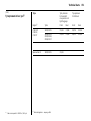
Data specific to your ve hicle
Please enter your vehicle’s data here to keep it ea sily accessible.
This information is available under the section "Technical da ta " as well as on the identification plate and in the Serv ice Booklet.
Fuel
Designati on
Engine oil
Gra de
Viscosity
Tyre pressure
Tyre si ze
for loa d wit h 1 p erson and
lig ht lugga ge
wi th full load
S ummer tyres
Front
Rear
Front
Rear
Winter tyres
Front
Rear
Front
Rear
Weights
Perm issi ble gross vehicle weight
–
EC k erb weight
=
Loading
Your Tigra
is an intelligent c om bina tion of forwardlooking technology, impressiv e safety ,
env ironmenta l friendliness a nd economy.
The R etractable steel roof also gives you
the opp ortunity to enjoy your Tigra as a
coupe or a convertible.
It now lies with you to drive your vehicle
safely and ensure that it perform s
perfectly. This O wner’s Manual provides
you with all the necessary information to
that end.
Make sure y our pa ssengers a re awa re
of the p ossible risk of accid ent and injury
which may result from im proper use of the
vehic le.
You m ust alway s comply w ith the sp ecific
laws of the c ountry that y ou are travelling
through. These laws ma y differ from the
inform ation in this Ow ner’s Manual.
When this Manual refers to a workshop
visit, we recommend your Vauxhall
Authorised Repairer.
All Vauxhall Authorised Repairers provide
first class service at reasonable prices.
You will rec eive quick, reliable and
indiv idua l service.
Exp erienced mechanics, trained by
Vauxhall, work according to specific
Vauxhall instructions.
The O wner’s Ma nual should alwa ys be kept
in the vehic le: R eady to hand in the g lov e
compartment.
Make us e of the Owner’s Manual:
z The "In Brief" section will give you an
initial overv iew.
z The ta ble of contents at the beg inning
of the owner’s manual and within the
individual chapters will show y ou where
every thing is.
z Its index will help you find what you
want.
z It w ill fa miliarise you with the
sophisticated technology.
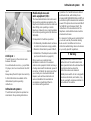
This sym bol signifies:
6 Continue read ing on next pa ge.
3 Items m arked with an asterisk are not
fitted to all v ehicles (model variants,
engine op tions, models specific to one
country, optional equipment, Genuine
Vauxhall Parts and Acc essories).
9 Warnin g
Text marked 9 Warning provides
information on risk of accident or injury.
Disregard of the instructions may lead to
injuries or endanger life.
Inform your passengers accordingly.
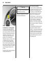
Y ellow arrows in the illustrations serve as
points of reference or indicate some action
to be performed.
Black arrows in the illustrations indicate
a reaction or a second action to be
performed.
Direc tional da ta, e.g. left or right, or front
or back, in the descriptions alway s relate to
the direction of travel.
z It w ill increase y our pleasure in your
vehicle.
Thank y ou for choosing a Vaux hall. We
wish you many hours of plea surable
driving.
z It w ill help you to handle your vehic le
expertly .
Your Vauxhal l Tea m
The O wner’s Manual is designed to be
clearly laid out and easily understood.
Contents
Comm itment to c ustomer
satisfaction:
Our ai m: to k eep you happy with your
vehicle. All Vauxhall Authorised Repairers
offer first-class serv ice a t competitiv e
prices. Experienced, factory-trained
technicians w ork according to factory
instructions. Y our Authorised Repa irer can
supply you with GEN UINE VAU XHALLAPPRO VED PARTS , which hav e und ergone
stringent quality and precision chec ks, and
of course useful and a ttrac tiv e
VAUXHALL-APPROVED AC CESSO RIES.
Our nam e i s your guara ntee!
For d eta ils of the
Va uxhall Authorised Rep airer Netw ork,
please r ing this number; 0845 090 2044
In Brief . ..... .... ..... .... .... ..... .... ..... .... ..... .... .... . 2
K eys, doors, w indows,
Retractable steel roof .... ..... .... ..... .... .. 20
S eats, Interior ..... .... .... ..... .... ..... .... ..... .... .. 46
Instrum ents, Controls .... .... ..... .... ..... .... .. 68
Lighting ..... .... ..... .... .... ..... .... ..... .... ..... .... .. 88
Infotainment system ..... .... ..... .... ..... .... .. 92
C lim ate c ontrol . .... .... ..... .... ..... .... ..... .... .. 94
Driving and Operation .. .... ..... .... ..... .... 102
S elf-help, vehicle care .... .... ..... .... ..... .... 132
Technical data . .... .... ..... .... ..... .... ..... .... 162
S ervice, Maintenance .... .... ..... .... ..... .... 175
Index . .... ..... .... ..... .... .... ..... .... ..... .... ..... .... 190
2
In Brief
In Brief
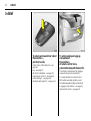
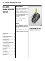
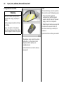
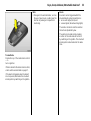
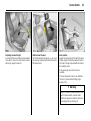
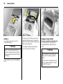
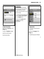
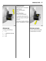
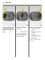
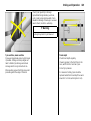
To unlock and open driver’s door:
Press bu tton q ,
pull door handle
6 Door locks, child safety locks – see
page 22,
key – see pag e 20,
electronic im mobilizer – see page 21,
ra dio remote control 3 – see p age 22,
central locking 3 – see page 24,
Vauxhall a la rm system 3 – see pag e 31.
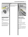
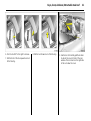
To unlock an d open luggage
com partment:
Press button q
of remote control twice,
press button beneath the boot lid
The vehicle is unlocked and the luggage
compa rtm ent opens automatically .
To unlock with button on driver’s door:
With vehicle unlock ed, ignition on and
hand brak e app lied, b riefly pull button R.
6 Luggag e comp artm ent – see page 27,
radio remote control – see p age 22.
In Brief
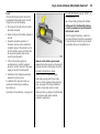
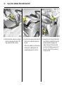
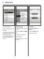
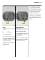
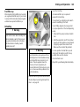
To adjust seat:
Pull han dle,
slide seat,
release handle
6 Seats – see page 46,
seat p osition – see page 47.
3
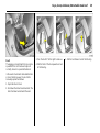
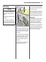
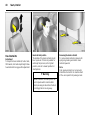
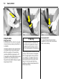
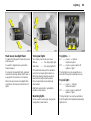
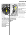
Adjusting seat backrest:
Turn handwheel
To adjust seat height:
Pull front lever at side
Move seat backrest to suit seating position.
Do not lean on seat b ackrest whilst
adjusting it.
Lift lev er and relieve some weig ht from seat
to raise it or press down on seat with body
weight to lower it.
6 Seats – see pag e 46,
seat position – see page 47.
6 Seats – see page 46,
seat position – see pag e 47.
9 Warning
Imp ortant: Do not sit nea rer than 10
inches (25 cm ) from the steering wheel, to
permit safe airbag dep loy ment.
4
In Brief
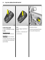
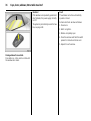
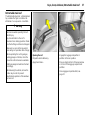
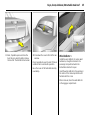
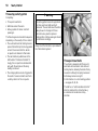
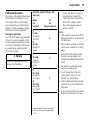
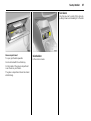
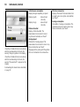
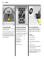
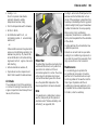
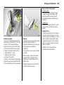
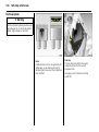
Folding down the seat backrests:
Raise release lever
To access the stowage comp artm ent
behind the seats, fold the front seat
back rests forward.
6 Seats – see page 46,
seat p osition – see page 47.
To adjust head restraint h eight:
To release catc h grip head
restraint at sides,
tilt forward,
hold and adjust height,
engage
6 Head restraints – pag e 48,
head restraint position – page 48,
head restraint removal – page 48.
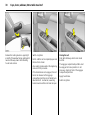
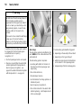
To fit seat belt:
Draw seat belt smoothly
from inertia reel,
guide over shoulder
and engage in buckle
The seat belt must not be twisted at any
point. The lap belt must lie snug ly against
the body. The backrests must not b e tilted
bac k too far (recomm ended tilting angle
app rox . 25° ).
To release b elt, p ress red button on belt
buckle.
6 Three-point safety belts – see pa ge 50,
airbag sy stem – see page 56,
seat position – see pag e 47.
In Brief
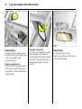
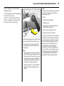
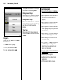
To adjust exterior mirrors:
Four-way switch on driver’s door
Adjusting in terior mirror:
Swivel mirror housing
Press mirror switch right or left: Four-way
switch adjusts corresponding mirror.
Swivel lever on underside of mirror housing
to reduce dazzle at night.
6 Mirrors – p age 34,
aspherical exterior m irror – page 34,
heated exterior m irror – pages 12, 95.
6 Mirrors – page 34.
5
6
In Brief
In Brief
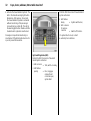
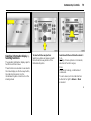
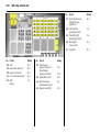
1
Page
Side air v ents ... ..... .... ..... .... .... ..... .... . 94
2
Front pa ssenger airbag .... .... ..... .... . 56
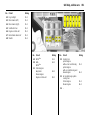
11
Pa ge
Windscreen wiper .... .... .... ..... .... 11, 87
Windscreen wash sy stem ..... .... . 11, 87
Page
18 Brake pedal .... .... ..... .... .... 72, 108, 123
12
Pa rk ing lights, dipped beam ... ... 9, 88
13
Head lig ht range adjustment ... ..... .. 90
Fog tail lig ht .... .... ..... .... .... ..... .... ..... .. 89
Fog lights 3 ..... .... ..... .... .... ..... .... ..... .. 89
Instrument illumination ... ..... .... ..... .. 91
20 Heated seats 3 .. ..... .... ..... .... ..... .... .. 95
3
Infotainm ent system 3 . .... .... .... 76, 93
4
Haza rd warning lights .. .... .... .... 10, 90
LED for anti-theft alarm sy stem 3. .. 32
5
Information display
for time, date,
outside tem perature,
Infotainm ent Sy stem 3 . .... .... ..... .... . 76
Trip computer 3 ... .... ..... .... .... ..... .... . 83
14
Bonnet release lev er . .... .... ..... .... .... 132
15
Starter switch with steering
wheel loc k ... ..... .... ..... .... .... ..... .... ..... ... 9
6
Centre air v ents .... .... ..... .... .... ..... .... .. 94
16
Steering wheel adjustm ent 3 ... ..... ... 9
7
Horn .... .... ..... .... ..... .... ..... .... .... ..... .... .. 11
Driver’ s Airbag ..... .... ..... .... .... ..... .... . 56
17
Ac celera tor pedal .... .... .... ..... 108, 110
8
Turn signal lights,.. .... ..... .... .... ..... 10, 89
head lig ht flash, .... .... ..... .... .... ..... 10, 89
Dipped beam, high b eam . .... ..... . 9, 89
Door-to-door light function 3 .... .... . 90
Cruise control 3 .... .... ..... .... .... ..... .... 120
9
Remote control on
steering wheel 3 .. .... ..... .... .... ..... .... . 92
10 Instruments... .... ..... .... ..... .... .... .... 68, 74
7
19 C lutch pedal 3 ... ..... .... ..... .... ..... .... 108
21 Accessory socket or
cigarette lighter . ..... .... ..... .... ..... .... .. 65
22 Ashtray 3 .... .... .... ..... .... ..... .... ..... .... .. 66
23 Air conditioning system 3 ... ..... .... .. 98
Heated rear w indow ... ..... .... ..... . 12, 95
Air recirc ulation system 3 .... ..... .... .. 99
24 C lim ate c ontrol .. ..... .... ..... .... ..... .... .. 94
25 Glove compartment ... ..... .... ..... .... ... 67
8
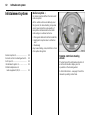
In Brief
Control indicato rs
X
S ea t belt 3 ,
see pa ges 68, 50.
>
Fog li ghts 3,
see pa ges 68, 89.
A
Engine elec tronics,
Immob ilizer ,3,
Easyt ronic 3,
Fault,
see pa ges 21, 69, 102, 114.
Z
Exha ust em issi on 3,
see pa ges 69, 114.
v
A irbag system s,
Belt tensioners,
see pa ges 52, 60.
I
Eng ine oi l pressure,
see page 70.
p
Alternator,
see p age 71.
O
Turn signal l ights,
see pages 10, 71, 89.
R
C
Mai n bea m,
see pages 9, 71, 89.
Brake system,
Clutch syst em ,
see p ages 72, 183.
u
!
Glow plugs 3,
see page 70.
Anti-lock Brak e S ystem 3 ,
see p age 125.
S
j
Easytronic 3,
Sta rt engine 3,
see pages 71, 103.
Engine oil l ev el 3,
see p ages 72, 179.
EPS
Electri c power steering 3,
see p age 72.
T
Easytronic 3,
Winter progr amme,
see page 105.
v
Electronic Stab ility Program
(ESP® Pl us ) 3,
see p ages 73, 118.
r
Fog tail light,
see pages 71, 89.
Y
Fuel level,
see p ages 73, 113.
y
Seat occup ancy r ecog ni tion 3,
see p ages 73, 61.
In Brief
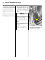
Steering wheel lock and ignition:
Turn key to position 1
Move steerin g wh eel somewhat
to release lock
Positions:
0 = Ignition off
1 = Steering free, ignition off
2 = Ignition on,
for diesel engine: p reheat
3 = Starting
To lock the steering w heel, switch ignition
off, rem ov e key and engage steering wheel.
6 Starting – pa ge 13,
electronic immobilizer – pag e 21,
parking the vehicle – page 14.
Steering wheel adju stment 3:
Swivel lever down,
adjust height,
swivel lever up,
engage
Ad just steering wheel only when vehicle is
stationary and steering column lock is
relea sed.
6 Airbag system s – page 56.
9
Light switch
7
= Off
8 = Parking lights
9 = Dipped beam
or main beam
Press button:
>
= Fog lights 3
r
= Fog tail light
0
= Courtesy light
6 Lighting – page 88,
headlight control indicator – pages 14, 86.
10
In Brief
Headlight flash, m ain beam and
dipped beam:
Headlight
= pull stalk
flash
towards
steering wheel
Main beam
= stalk forwards
Dipped beam = stalk forwards
again
Main beam, headlight flash – pag e 89.
Switch on turn signal lights:
right
= stalk up
left
= stalk down
Hazard warning lights:
on
= press ¨
off
= press ¨ again
6 Turn signal lights – p age 89.
6 Hazard warning lig hts – page 90.
In Brief
Operate horn:
j press right or left
6 Airbag sy stem – page 56,
rem ote control on steering wheel 3 –
page 92.
Wiper:
Mo ve stalk up
§
= off
$ = adjustable tim ed interval
wipe
% = slow
& = fast
6 wiper – p age 87,
adjustable timed interval wipe 3 –
page 87,
further notes – pages 160, 185.
11
Operating windscreen system:
Move stalk toward steering wheel
The wiper w ill swipe for a few strok es.
6 Screen wash system – page 87,
further notes – p ages 160, 185.
12
In Brief
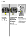
Heated rear window,
heated exterior mirrors:
on
= press Ü
off = press Ü again
6 Air c onditioning – pa ge 94,
heated rear window – page 95.
To clear misted or icy windo ws:
Turn rotary switch for
temperature and air flow
clo ckwise,
set air distribution to V;
Air con ditioning system 3:
Also press button n
6 C lim ate control system 3 – p age 94.
Man ual transmission:
Reverse gear: with v ehicle stationary, three
seconds after de-clutching pull the ring up
and engage g ear.
If the gea r does not engag e, set the lever
in neutral, release the clutch pedal and
depress again; then repeat g ear selection.
In Brief
13
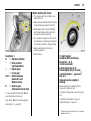
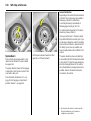
Before starting off, check:
z Tyre pressure and ty re condition, see
pages 126, 170.
z Engine oil level and fluid levels in engine
compa rtm ent, see pages 179 to 185.
z All windows, mirrors, ex terior lighting
and number plates a re free from dirt,
snow and ice and opera tional.
z Do not place any objects in front of the
rea r window, on the instrument panel or
in the area in w hich the airbags infla te.
z Seats, seat b elts and mirrors are
correctly adjusted.
Easytronic 3:
N
= Idle/start position
o
= Drive position
(centre position)
+
= Higher gear
= Lower gear
A/M = Switch between
Au to matic and
Manual mode.
R
= Reverse gear
(with selecto r lever lock)
z C heck bra kes.
To start engine:
Operate clutch and brake,
Easytronic 3 in N,
do no t accelerate,
petrol engine: key to 3;
diesel engine: key to 2, when
con trol indicator ! goes out1) ,
key to 3;
release key once engine is
running
Before restarting or switching off the
eng ine, turn key bac k to 0.
To move the selector lever from N to R
press the b utton on the lever.
To switch on the ignition, only turn the key
to 2.
O nly start in N with foot brake applied.
6 Electronic im mobilizer – Page 21,
Diesel fuel system – Page 132.
6 Easytronic 3 – page 102.
1)
Preh eatin g system sw itches on o nly if outside
tem perature is low .
14
In Brief
Advice when parking:
z Do not park the vehicle on fla mmable
ground as com bustion could occur due
to the high exhaust tempera tures.
z Alw ays apply the hand brak e firmly .
Apply the hand brake as firmly as
possible on uphill or downhill slop es.
To reduce operating forces, depress
foot b ra ke at the same time.
z Close windows and Retractable steel
roof.
Releasing th e hand brake:
Raise lever slightly,
press lock bu tto n,
lower lever fully
6 Hand brake – page 124.
Parking the vehic le:
Apply hand brake firmly,
engine off,
remove key,
loc k steering wheel,
loc k vehicle
To lock and activ ate the Va ux ha ll alarm
sy stem 3, press button p . To a ctiv ate the
anti-theft lock ing sy stem 3 and Vaux hall
alarm system 3, press button p twice.
6 Further information – see p ages 21, 108,
ra dio remote control – see page 22,
central locking system – see page 24,
Vauxhall a la rm system 3 – see pag e 31,
vehicle dec om missioning – see page 187.
In Brief
z With manual transmission, select first
gear or reverse gea r, with Easytronic 3
move selector lever to c entre p osition
before switching ignition off.
z On vehicles with Ea sytronic 3 control
indica tor R flashes for a few seconds
after the ig nition is switched off if the
hand brake has not been a pplied– see
page 106.
z Turn steering wheel until lock is felt to
engage (anti-theft protection) after first
withdraw ing the ignition key .
z The engine cooling fa ns ma y run after
the engine has been sw itched off, see
page 178.
6 Further information – see pages 186, 187.
9 Warning
C arry out regularly the check s
rec om mended in the indiv idual sections
of this Owner’ s M anual.
Ensure that your v ehicle is serv iced at the
service intervals spec ified in the Serv ic e
Booklet. We recommend that you entrust
this work to your Vauxhall Authorised
Repairer.
Hav e faults remedied without d elay!
C onsult a w orkshop. We recommend your
Vauxhall Authorised R epairer. If
necessary , interrupt your journey.
6 Maintenance – see page 162.
15
That was the most important
information for your first drive
in your Tigra in brief.
The other pages o f this chapter
con tain a description of some
interesting fun ction s in your
vehicle.
The remain ing ch apters
of the Owner’s Manual
con tain impo rtant information
on operation, safety and
maintenance as well as
a com plete index.
16
In Brief
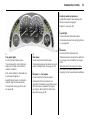
Airbag System
The a irb ag system c onsists of several
separate systems.
Front airb ag system
The front airbag system will be triggered
in the event of a serious accid ent inv olv ing
a frontal im pact and forms safety c ushions
for the driver and front passenger. The
forward movement of the driver and front
passenger is checked and the risk of
injuries to the upper body a nd head
thereby substantially reduced.
Side airb ag system
The sid e airbag is triggered in the event of
a side-on c ollision to form a safety cushion
for the driver or front passenger in the
respective door area. This substantially
reduces the risk of injury to the upp er body
and pelv is.
6 Airbag system s – page 56.
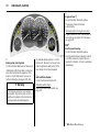
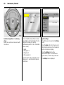
Operating m enu s in
the information display
3
Menu op tions are selected using menus and
using the buttons/four-way button or the
multi-function button of the I nfotainm ent
system 3 or the buttons 3 on the steering
wheel. The respectiv e menu options are
shown on the display.
S elec tion using four-way button:
press four-w ay button at top, bottom , left
or right.
In Brief
Ü
Board Computer
BC 1
1
8
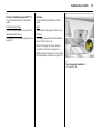
Selection using multi-function button 3 :
rotate a nd press multi-function button.
To exit a m enu, turn the multi-function
button left or right to Return or Ma in
and select.
To select w ith steering wheel buttons 3
Select menu options via the menus and
the buttons.
6 Information Display – p age 76.
19,5° 19:36
All values
BC 2
Timer
17
257.0
40
6.0
Ø 7.0
Ø
miles
mph
gals
miles/ gal
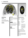
Trip computer
3
The trip comp uters provide informa tion on
driving da ta , which is continually recorded
and evaluated electronica lly .
Functions:
z Range
z Instantaneous consumption
z Distance travelled
z Average speed
z Effective consum ption
z Average consum ption
z Stop watch
6 Board computer – see page 83.
18
In Brief
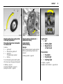
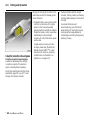
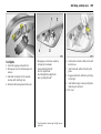
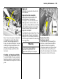
Opening Retractable steel roof
O nly with vehicle stationary .
z Engage hand brake.
z Release the locking levers on upper rig ht
and left of the window fram es, pulling
both lev ers all the way d ow n. The
reta ining hook m ust unhook.
z Switch on ignition.
z Pull S until the roof is completely open
and the b oot lid is closed .
z Engage the luggag e com partment
partition in the rear position.
An acoustic signal sounds at the
beginning and end of the p rocedure.
z Place no objects in front of the rear
wind ow or in front of the lugg age
com partment p artition.
If the hand brake is not engaged, the
roof lock is not released or the luggage
compartment partition is not folded back
when button S is actuated, a wa rning
buzzer sounds and the roof does not
open.
z Close the boot lid .
6 Retractable steel roof – see page 37.
In Brief
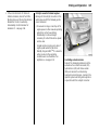
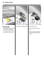
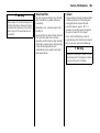
Closing Retractable steel roof
O nly with sta tionary vehicle and closed
boot lid.
The lugga ge com partment pa rtition must
be engag ed in its rear position. Do not
place any ob jects in front of the lugg age
compartment partition.
z Engage hand brake.
z Switch on ignition.
z Press S until the roof and boot lid are
com pletely closed.
An a coustic signal sounds at the
beginning and end of the procedure.
If button S is actuated when the hand
brake is not engag ed, a warning buzzer
sounds and the roof rem ains open.
19
z Move the locking levers on right and left
of the w indow fra mes all the way up .
Each retaining hook must engage and
the roof must lock sec urely.
Parkin g distance sensor 3
6 Retra ctable steel roof – see pa ge 37.
If the vehicle approaches an obstacle when
rev ersing, a series of sig nals can be heard in
the v ehicle interior. The interval between
the signals becomes shorter as the distance
is red uced. If the distance is less than 30 cm,
the signal will be continuous.
When rev erse gear is selected, the Parking
distance sensor switches itself on
automatically.
6 Parking dista nce sensor 3 – page 122.
20
Keys, doors, windows, Retrac table steel roof
Keys, doors,
windows, Retractable
steel roof
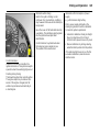
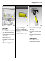
Replacement keys
The key number is specified in the vehic le
docum ents and in the C ar Pass 3.
The key is a c onstituent of the electronic
immobilizer. O rd ering keys from a Vauxhall
Authorised Repairer g uarantees problem free op eration of the electronic
immobilizer.
Keep the sp are k ey in a safe spot.
Locks, see pa ge 160.
Car Pass
Replacem ent keys ... ..... .... ..... .... .... ..... .
Ca r Pass... .... .... ..... .... ..... .... ..... .... .... ..... .
Key with retractable key blade 3 ..... .
Electronic immobilizer .. .... ..... .... .... ..... .
Radio remote control ... .... ..... .... .... ..... .
Central locking system . .... ..... .... .... ..... .
O perating central loc king system with
key in driver’s door lock . ..... .... .... ..... .
Lug gage compartment .... ..... .... .... ..... .
Vauxhall alarm system 3. ..... .... .... ..... .
Ex terior mirrors..... .... ..... .... ..... .... .... ..... .
Interior mirror .. ..... .... ..... .... ..... .... .... ..... .
Electric windows... .... ..... .... ..... .... .... ..... .
Retra ctable steel roof... .... ..... .... .... ..... .
Wind deflector 3.. .... ..... .... ..... .... .... ..... .
20
20
20
21
22
24
27
27
31
34
34
35
37
45
The Ca r Pass contains a ll of the vehicle’s
data and should therefore not be k ept in
the vehicle.
Key with retractable key blade
Have your Ca r Pa ss on hand when
consulting a Vaux hall Authorised Repairer.
Press button to extend. Press button to
retrac t; key section eng ages audibly .
3
Keys, do ors, windo ws, Retractable steel roof
21
If c ontrol indicator A illuminates a fter
the engine is started, there is a fault in
the engine elec tronics or transmission
electronics 3 (see pages 69, 107, 115)
or there is water in the diesel fuel filter 3,
see page 181.
Not e
The immobilizer does not lock the doors.
Therefore, alwa ys lock vehicle before
leaving unattended and ena ble Vauxhall
alarm sy stem 3 see p age 24.
Electronic immo bilizer
Using a transponder housed in the key , the
system checks whether the vehicle may be
started using the key that has been
inserted. If the k ey is recognised as
"authorised" the engine can be started.
The electronic imm ob iliz er activa tes
automatically when the k ey is removed
from the starter switch.
The c od e number of the electronic
immobilizer is given in the Ca r Pass.
Control i nd icator for imm obilizer A
Control indica tor A illuminates briefly
when the ig nition is sw itched on.
If the control indicator flashes w hen the
ignition is on, there is a fault in the sy stem;
the engine cannot be started. S witc h off
the ignition and then rep eat the start
attempt.
If the control indicator A continues to
flash, try to start the engine using the
second key and c ontact a workshop for
assista nce.
22
Keys, doors, windows, Retrac table steel roof
Radio remote control
Dep ending on equipment level, the vehicle
comes equipped with one of the remote
controls depicted on this pag e.
The rad io remote control is integrated in
the k ey.
Used to op erate:
z central locking system,
z mechanical anti-theft locking system 3,
z Vauxhall ala rm system 3 .
The w indows can also be closed using the
radio remote control.
The radio remote control has a range
of approx. 5 m etres. This range can be
affected by outside influences. Aim the
remote control at the vehicle to operate.
C entra l lock ing system,
see page 24.
Handle the radio remote control with
care, protect it from m oisture and hig h
temperatures and avoid unnecessary
op eration.
Vauxhall ala rm system 3,
see page 31.
The hazard warning lig hts come on
to indic ate that the remote control is
op erational.
Mechanic al anti -theft locki ng system 3 ,
see page 25.
Electric w indows,
see page 35.
Keys, do ors, windo ws, Retractable steel roof
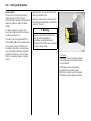
Fault
If the central locking system cannot be
opera ted with the radio rem ote control,
it may be due to the follow ing:
K ey with fix ed blade, see Fig. 15331 T on
previous pa ge.
Hav e the workshop chang e the battery .
I n the ev ent of a functionali ty p roblem
or b attery rep lacement, sync hronize the
rad io remote control .
z The range of the radio remote control
has been exceed ed.
z Radio rem ote control battery voltage is
too low.
After c hanging the battery , unlock the
door using the key in the lock, see overleaf.
The ra dio remote control is synchroniz ed
by inserting the key in the ignition lock.
z Freq uent, rep eated opera tion of
the radio remote control outside the
recep tion range of the v ehicle (e.g. too
far from vehicle, remote control is then
no longer recognised). S ee rem ote
control synchronisation.
z If the centra l loc king sy stem is
ov erloaded as a result of repeated
op eration at short interv als. The power
supply is c ut off for a b rief period.
z Interference from higher-power radio
waves from other sources.
To elim inate the cause of a fault, we
recom mend contacting a workshop
for assistance.
O pen driver’s d oor with key – see page 27.
23
Rem ote control b attery rep lacement
Replace the battery as soon as the range of
the radio rem ote control begins to shrink .
Key with retrac ta ble k ey blade,
see Fig. 15330 T on previous pa ge.
Extend key, see pa ge 20. O pen rad io
remote control. Replace battery (battery
type, see page 172) noting installation
position. C lose radio remote control.
Make sure that you dispose of old batteries
in accordance with environmental
protection regulations.
24
Keys, doors, windows, Retrac table steel roof
Cen tral locking system
For doors, b oot lid/tailgate and tank flap.
To unlock
Unlock driver’s door only
Press button q on rem ote control onc e.
Unlock entire car
Press button q on rem ote control twice.
The vehicle ca n also be unlocked by pulling
the d oor handles if the anti-theft locking
system is disabled.
To lock
Close doors, luggage compartment and
tank flap.
Press button p on radio remote control.
– or from the inside –
Press button m in the d oor.
The vehicle can be loc ked even if the d river’s
door is open. Risk of being locked out.
Keys, do ors, windo ws, Retractable steel roof
Note
z 30 second s a fter unlock ing using the
radio remote c ontrol the d oors lock
again a utomatica lly if no door is
opened.
z To lock the doors from inside (e.g. to
prevent unwanted entry from outside),
press central lock ing switch m in the
door trim.
Mechanica l anti-t heft locking system 3,
9 Warning
Do not use the sy stem if there are people
in the vehicle! The doors cannot be
unlocked from insid e.
All doors must b e closed. No m ore than
10 second s a fter locking, press button p
on the rad io remote control ag ain.
Loc k buttons on all d oors are positioned
suc h that doors cannot be opened.
If the ignition was on, the driver’ s door
must be opened and closed once so tha t
the v ehicle can be secured.
25
z The vehicle ca n be lock ed w ithout the
need for the key. With the driver’s door
open, p ress c entral locking switch m in
the door trim and then close the driver’s
door. Note tha t unintentional actuation
could cause one to be lock ed out.
z Locked doors and luggage compartment
unlock automatically in the event of an
accident of a certa in sev erity (to permit
outside assistance). Prerequisite: Ignition
must not be switched off.
26
Keys, doors, windows, Retrac table steel roof
Cl osing window s fr om outside
Fault
If the central locking cannot be operated,
this can be for one of the following reasons:
9 Warning
z If the central locking system is
overloaded as a result of repeated
operation at short intervals. The power
supply is cut off for a brief period .
Exercise care when operating electric
wind ows. Risk of injury, especially for
children.
Vehicle passengers should be informed
according ly .
z Defec tiv e fuse in fuse box , see p age 148.
To elimina te the cause of a fault, w e
recommend contac ting a workshop for
assistance.
Keep a close watch on the wind ow s
when closing them. Ensure tha t nothing
becomes trapped in them a s they move.
O perate driver’s door with key, see overleaf.
The windows can be closed from outside:
hold button p on the remote control
depressed until the windows are
completely closed.
Further inform ation on electric wind ow s,
see p age 35.
Keys, do ors, windo ws, Retractable steel roof
27
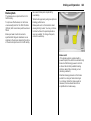
To lock
With doors closed, turn key towards rear of
vehicle as far as it will g o. Turn key back to
vertical p osition and rem ove.
Operating central locking system
with key in driver’s door lo ck
To unlock
Turn k ey forward in lock as far as it w ill go.
Turn key back to vertical position and
rem ov e.
If the anti-theft lock ing sy stem 3 is
enga ged, only the driver’s d oor will unlock .
To unlock the entire car: switch on the
ignition, press central locking switch m
and pull the driver’ s d oor handle.
Luggage com partment
To open wi th the button in t he d oor
1. Unlock entire vehicle – see pag e 24.
2. Apply hand b ra ke.
3. Switch on ignition.
4. Briefly press button R. The opening
process begins after a slight d elay.
A second press of the button stops the b oot
lid from opening .
If the hand brak e is not eng aged w hen the
button is pressed , a warning buzz er sound s
and the luggage compartment rema ins
closed.
28
Keys, doors, windows, Retrac table steel roof
A tone sounds when the boot lid is
completely closed. Loc king of the boot lid is
indicated by a sing le flash of the hazard
warning lights.
To open wit h the b utton beneath the
boot l id
1. Unlock entire v ehicle – see page 24.
To close
Press the button b elow the boot lid until
the boot lid is completely closed.
2. Briefly press the button beneath the
boot lid . The opening process beg ins
after a slight delay.
If the ignition is on b ut the hand brake is
not a pplied when the b utton is pressed,
a warning buzzer sound s and the lugga ge
compartment closes.
A second p ress of the button stops the
boot lid from opening.
If the ignition is on but the hand brake is
not applied when the button is pressed,
a w arning buzzer sounds and the luggage
compartment rem ains closed.
Keys, do ors, windo ws, Retractable steel roof
Fault
The luggag e com partment lid c an only be
opera ted if the roof has been fully a nd
correctly closed or opened beforehand.
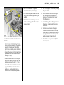
In the event of automatic driv e malfunc tion
or loss of battery power, the boot lid is
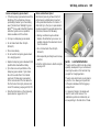
manually opened as follows:
1. Open the driver’s door.
2. Fold down the driver’ s seat backrest. The
tool is fastened underneath the seat.
3. Turn the tool 90° to the right to rem ove.
4. Pull the front of the tool upwa rd and out
of the flooring.
29
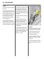
5. Pull the tool forwa rd out of the flooring.
30
Keys, doors, windows, Retrac table steel roof
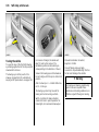
6. Open and fold down the cover of the
emergency release cable. Pull the c able
out slightly.
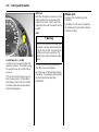
8. Hav e a second person hold the rear of
the boot lid down. Pull the tool forward
to release the boot lid in the rear.
To close the boot lid , hav e a second person
help y ou press it down and engage it in the
lock.
7. Insert the tool through the ey e of the
emergency release cable. S up port the
rounded end of the tool on the cover
as illustra ted. The ey e of the emergency
release cable must lie in the groov e on
the tool.
9. C arefully open the boot lid by hand.
Hav e the cause of the fa ult eliminated by
a work shop.
Refit the emergency release cable in the
op ening and refit the cover. Do not close
the car d oor if the cover is open.
Keys, do ors, windo ws, Retractable steel roof
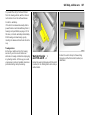
Vauxhall alarm system
31
3
monitors
z doors, luggag e com partment, b onnet
z the passenger c om partment
z vehicle tilt, e. g. if it is raised
z the ignition.
9 Warning
Do not use the sy stem if there are people
in the vehicle! The doors cannot be
unlocked from the inside.
To activ ate
All doors, w indows, R etractable steel roof,
lugg age compartment a nd bonnet must
be c losed . Press button p on the remote
control to lock all the doors and activa te
the Vauxhall alarm system 3.
If the ignition wa s switched on, the driver’s
door must b e opened a nd closed once so
that the Vauxhall alarm system can be
switched on.
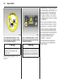
Act ivat ion without monitoring of
pa ssenger comp artment a nd vehicle ti lt
e.g. if anim als a re to be left in the vehic le.
1. The luggage compa rtm ent, Retractable
steel roof and b onnet must b e closed.
2. Press the button in front of the courtesy
lig ht (with ignition off); LED in hazard
warning light button flashes a max imum
of 10 seconds. See next page.
3. Close doors.
32
Keys, doors, windows, Retrac table steel roof
4. Activ ate the Vaux hall alarm system . The
LED in the hazard warning light button
illuminates. After approx. 10 sec onds,
the Vaux hall alarm system is activated
without monitoring of the passenger
com partment or v ehicle tilt. The LED in
the warning light button flashes until the
Vauxhall ala rm system is deactivated.
After the first 10 seconds of Vauxhall alarm
system activation:
Passeng er comp artm ent monitoring is
deactivated if the Retractable steel roof is
open to prevent false alarms.
If a sy stem fault occurs, contact
a work shop for assistance.
z LED flashes
slowly
=
z LED comes on
for approx.
1 second
=
Lig ht emitt ing diode (LED)
During the first 10 seconds of Vauxhall
alarm system activation:
z LED com es on =
z LED flashes
quickly
=
Test, switch-on delay ,
Door, luggage
compa rtm ent
or bonnet open,
system fault.
Sy stem switched on,
Switch-off function.
Keys, do ors, windo ws, Retractable steel roof
Note
z C hanges to the vehicle interior, such as
the use of seat covers, could impair the
func tion of pa ssenger compartment
monitoring.
33
Ala rm
An alarm can be triggered whilst the
Vauxhall alarm system is sw itched on:
z an acoustic signal (horn) a nd
z a visual sig nal (haz ard warning lights).
The numb er of alarms and the duration
thereof are stipulated by law .
The alarm can b e silenced by pressing
a button of the ra dio remote control or
by sw itc hing on the ignition. The Vaux hall
alarm sy stem is deactivated at the sam e
time.
To deacti vate
Press button q of the radio remote control
– or –
turn on ig nition.
If there is a fault in the radio remote control,
unlock vehicle as described on p age 27.
If the alarm is triggered when the driver’s
door is opened, deactivate the Vauxhall
alarm system by switching on the ignition.
34
Keys, doors, windows, Retrac table steel roof
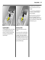
Exterio r mirrors
Adjustment using the four-way switch in
the d riv er’s door. Press mirror switch right
or left: Four-way switch ad justs
corresponding mirror.
Aspherical exterior mi rror 3
increases the field of view. Estim ating the
distance aw ay of vehicles follow ing you is
only possible to a lim ited extent because
of slig ht d istortion.
Swingi ng in exterior mirror
For the safety of pedestrians, the exterior
mirrors will swing out of their normal
mounting position if they are bumped w ith
sufficient force. Reposition the mirror by
applying slight pressure to the m irror
housing.
Interio r mirror
To adjust, swivel mirror housing .
S wivel lever on underside of m irror housing
to reduce d azzle at night.
Keys, do ors, windo ws, Retractable steel roof
35
When a door is opened, the window of that
door opens a slit. It closes autom atically
after the door is closed.
Electric windo ws
9 Warning
When the Retractable steel roof is opened
or closed, the windows open a slit. They
close a utomatica lly once the Retracta ble
steel roof is com pletely opened or closed.
Exercise care when operating electric
wind ows. Risk of injury, especially for
children.
Vehicle passengers should be informed
according ly .
Sa fet y functi on
If the window glass encounters resistance
abov e the middle of the window d uring
automatic c losing, it is imm ediately
stopped and the w indow opened again.
Keep a close watch on the wind ow s
when closing them. Ensure tha t nothing
becomes trapped in them a s they move.
Ready for operation when the ignition is on.
Operation w ith two switches in the driver’s
door handle for the driver’ s and passenger
wind ow . Additional switch in passenger
door ha ndle.
To operate wind ow in sta ges, briefly pull or
push relevant window switch. For automatic
opening or closing, pull or push switch
longer; push or pull switch again to stop
movement.
Automatic closing is not possible during
Retractable steel roof operation.
If the windows do not move easily because
of frost, for exam ple, repeatedly tap the
switch for the window in q uestion until the
window has been closed in stages.
36
Keys, doors, windows, Retrac table steel roof
Overloa d
If the windows are repeatedly operated at
short intervals, the power supply is b riefly
cut off.
Fault
The wind ow s c annot be automatically
opened or closed.
The system is protected by fuses in the fuse
box, see pag e 148.
1. Close doors.
Activate electronic windows as follows:
2. Switch on ignition.
3. Window com pletely open.
4. Close the windows and hold the switch
pressed for at least another second.
5. Repeat for ea ch window.
Cl osing window s fr om outside
Press button p on the remote control until
the w indows are closed.
Keys, do ors, windo ws, Retractable steel roof
37
Retrac table steel roof
The Retractable steel roof, a folda ble steel
top, enables the Tig ra to combine the
attributes of a coupe and a conv ertible.
9 Warning
Exercise care when operating the roof.
Risk of injury.
Pay close attention to the roof’s
movem ent zone during operation. Make
sure that nothing could bec om e trapped.
Make sure no one is in the mov ement
zone during roof operation. Risk of injury .
Before operating the roof in garages,
parking garages or the like, check the
amount of v ertical clearance available.
Vehicle passengers should be informed
according ly .
Before leaving the vehicle, remove the
ig nition key in order to prev ent
unauthorised operation of the w indows
and sun roof.
Opening t he roof
Only w ith v ehicle stationary.
Eng age the luggage compartment
partition in the rear position.
Ap ply hand brak e.
Place no objects in front of the rea r window
or in front of the luggage compartm ent
partition.
C lose lug gage compartment lid , see
pag e 27.
38
Keys, doors, windows, Retrac table steel roof
Release the locking levers on upper rig ht
and left of the window fra mes, pulling both
lev ers all the way d ow n. Both retaining
hooks must unhook .
Switch on ignition.
Pull S until the roof is completely open and
the boot lid is closed.
An acoustic signal sounds at the b eginning
and end of the proced ure.
If the hand b ra ke is not enga ged, the roof
lock is not released or the lugga ge
compartment partition is not fold ed b ack
when button S is actua ted, a warning
buzzer sounds and the roof does not open.
C losi ng the roof
O nly with stationary vehicle and closed
boot lid.
The lugg age compartment p artition must
be enga ged in its rear position. Do not
place any objects in front of the luggage
compa rtm ent partition.
Apply hand brake.
S witc h on ig nition.
Keys, do ors, windo ws, Retractable steel roof
Press S until the roof a nd boot lid are
completely closed.
39
Fault
Automatic roof operation is only func tional
if the roof has been properly closed or
opened beforehand.
An a coustic signal sounds at the beg inning
and end of the p rocedure.
C heck if:
If button S is actuated when the hand
brake is not engaged, a warning buzzer
sounds and the roof remains open.
z the hand brak e is applied
z the ignition is on
z the luggage compa rtm ent partition is
loc ked in the rea r position
z the boot lid is comp letely closed
z the locking levers are unlock ed.
Push the locking levers on the right a nd left
side of the w indow fram e a ll the way up.
The retaining hooks must engage in the
corresp onding recess and the roof m ust
securely lock .
Note
z A warning buzz er sounds for 5 seconds
after the hand b ra ke is released and the
vehicle starts off if the roof has not been
properly closed or opened. Rem edy this
by stopping the vehic le and repeating
the closing or opening p rocedure.
z Frequent operation of the roof with the
eng ine switched off will discharge the
battery.
If a fault occurs while the roof is opening or
closing, the roof stops in its current position.
A warning buzzer sounds after 2 minutes.
After an add itional minute, power to the
system is cut-off. The roof then moves
automatically back to the luggage
compartment or toward the wind screen
frame. In order to close completely, open
both windows, remove the key and carry
out the missing steps of the following
description for loss of automatic drive.
40
Keys, doors, windows, Retrac table steel roof
If there is a fault in the a utoma tic drive or
loss of battery power, the fully opened roof
can be ma nually closed as follow s:
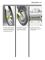
1. Park the v ehicle a nd apply the hand
brake.
2. Open both windows or op en the d oors.
3. Switch off the ignition and rem ove the k ey.
4. O pen the lug gage compartment. If the
battery has become discharged or there
is a malfunction in boot lid operation, the
boot lid m ust be opened ma nually; see
page 29.
9 Warning
Exercise care when operating the roof.
Risk of injury . Risk of pinching.
Mak e sure that nothing could bec om e
trapped.
Vehicle passeng ers should be inform ed
accordingly.
C losing the roof manually requires
2 persons and the use of g reat care.
5. Fold down the driver’s seat backrest. The
tool is fastened und erneath the seat.
Keys, do ors, windo ws, Retractable steel roof
6. Turn the tool 90° to the rig ht to remove.
7. Pull the front of the tool upward and out
of the flooring.
8. Pull the tool forward out of the flooring .
41
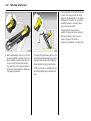
9. Use the tool to forcefully pull the lock bar
to unlock the cover in front of the rear
window. The lock bar is on the rig ht side
of the car b elow the cover.
42
Keys, doors, windows, Retrac table steel roof
10. With the lock bar pulled, hav e a helper
pivot the cover upwa rd by hand. The
noise arising from this is norma l.
11. Press the b utton below the boot lid until
the boot lid is completely closed. See
pa ge 28.
I f this is not possible, forc e the boot lid
closed again as illustrated; it m ust
com pletely enga ge in the rear lock .
12. Release the front catches of the boot lid
using the tool by inserting the tool in the
guide and pressing the upper end
inward; see figure. At the same time,
pull the b oot lid slightly upw ard out of
the ca tch. Carry out the procedure on
the right and left.
Keys, do ors, windo ws, Retractable steel roof
13. With two p eople working simultaneously
on the right a nd left, open the boot lid
rearward to its end position. Do not twist
or tilt the boot lid when doing so.
9 Warning
Luggage compa rtm ent does not remain
in open position.
14. Release the roof retainer at the rear left
of the lug gage compartment partition
by raising the release lever.
43
15. With the aid of a second person,
carefully and slowly pull the roof
upward. Grip the roof at the sides and
pull forward. Ma ke sure that the boot
lid is completely op en.
9 Warnin g
Caution. Risk of pinching .
44
Keys, doors, windows, Retrac table steel roof
16. Pull the roof up to the w indscreen frame.
17. Push the lock ing levers on the rig ht and
left side of the wind ow frame all the
wa y up.
The retaining hook s must enga ge in the
corresponding recess a nd the roof must
sec urely lock.
18. Have a second person help to force the
boot lid closed simultaneously on the
right and left. It must engag e in the
locks.
Do not twist or tilt the boot lid.
The closed boot lid is not loc ked.
Keys, do ors, windo ws, Retractable steel roof
19. Next, if possib le open and close the
boot lid once using the b utton below
the boot lid . The boot lid is then locked.
20. Press d ow n the cover in front of the rea r
window.
It is not possible to open the roof if there is
a malfunction in a utoma tic operation.
Have the ca use of the fault eliminated by
a workshop.
45
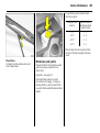
Win d deflector
3
Install the wind deflec tor to reduce wind
turbulence, draught and noise in the
passenger compartment when the
Retractable steel roof is open.
Insert the wind deflector in the opening in
the centre of the rollov er protection a nd
fasten it with the crank.
When removed , store the wind deflector
in the lugg age compartment.
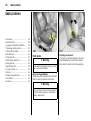
46
Seats, Interior
Seats, Interior
Front sea ts .. .... ..... .... ..... .... ..... .... .... ..... .
Head restraints .... .... ..... .... ..... .... .... ..... .
Lug gage compartment partition . ..... .
Three-stage safety sy stem.... .... .... ..... .
Three-point seat belts .. .... ..... .... .... ..... .
Belt tensioners. ..... .... ..... .... ..... .... .... ..... .
Using the belts ..... .... ..... .... ..... .... .... ..... .
Child restraint systems 3 . ..... .... .... ..... .
Airbag S ystem. ..... .... ..... .... ..... .... .... ..... .
Ciga rette lig hter 3 ... ..... .... ..... .... .... ..... .
Accessory socket 3.. ..... .... ..... .... .... ..... .
Ashtray 3 .... .... ..... .... ..... .... ..... .... .... ..... .
Stowage comp artm ents... ..... .... .... ..... .
Coin holder 3 .. ..... .... ..... .... ..... .... .... ..... .
Sun visors. .... .... ..... .... ..... .... ..... .... .... ..... .
46
48
49
50
50
52
54
55
56
65
65
66
66
67
67
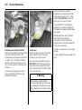
Front seats
9 Warning
Never adjust seats during driving, as they
can m ov e uncontrollab ly .
Adjust seat longi tudinally
To adjust, p ull the handle on the front seat,
slide the seat and release the handle.
9 Warning
Do not sit nearer than 10 inches (25cm)
from the steering wheel, to p ermit safe
airbag deploy ment.
Ad just ing the bac krest
To adjust, turn sid e handwheel on the seat
while releasing the load on the b ackrest.
Move seat bac krest to suit sea ting position.
Seats, Interior
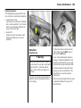
Adj usti ng the seat hei ght
To a djust, lift lev er and relieve some weight
from seat to ra ise it or press down on seat
with body weight to lower it.
Fold back rest forward
To fold the b ackrest forwards, e.g . to rea ch
the stora ge compartment behind the seats,
lift release lever.
47
Seat position
Adjust driver’s sea t such that with the driver
sitting upright the steering wheel is held in
the area of its upp er spokes with the driver’s
arms slightly b ent.
Push p assenger seat as far b ack as
possible.
The seat back rests m ust not be tilted too
far ba ck (recom mended tilting angle
app rox . 25° ).
9 Warnin g
Failure to observe the descriptions could
lead to injuries which could be fatal.
Vehic le pa ssengers should be informed
accordingly before starting off.
48
Seats, Interior
Head restraints
Adj ustm ent
To adjust the hea d restraints, hold at side,
tilt forwards, hold and adjust height. Allow
head restraints to engage after adjustment.
Hea d rest raint p osi tion
The middle of the head restraint should
be a t ey e level. If this is not possible for
extremely tall persons, set to highest
position, and set to low est position for
sma ll persons.
9 Warning
Failure to observe the descriptions can
lead to injuries whic h could be fata l.
Vehicle passeng ers should be inform ed
accordingly before moving away .
Remov ing the head restraint s
To remove head restraints, release b oth
springs b y pressing and detach hea d
restraint upwards.
Not e
O nly approved objects or com ponents
should be a tta ched to the head restraint
of the unoccupied front p assenger seat.
Seats, Interior
Place no objects in front of the luggage
compa rtm ent partition.
Luggage compartment partition
When the Retractable steel roof is closed,
the p artition can b e folded forward to
enlarge the lugg age com partment: pull
both catches inward and fold the partition
forward until it engages.
If the Retractable steel roof is to be
op ened , pull the c entre of the partition,
relea se it and fold it rearward until it
engages.
49
50
Seats, Interior
Three-stage safety system
Com prising:
z Three-point seat belts.
z Belt tensioners at the seats.
z Airbag sy stems for driver and front
passenger.
The three stages are activated in sequence
depending on the sev erity of the accident:
z The automatic seat belt locking d evices
prevent the belt strap from b eing pulled
out and thus ensure that the vehicle
occ upa nts are retained in their seats.
z The seat belts are p ulled down at the
belt buckles. This m eans the b elts fit
snugly, the occupants are d ecelerated
early with the vehic le and the body
load ing is reduced .
z The airbag systems are also triggered in
the ev ent of severe accidents and form
a safety c ushion for the occupants.
9 Warning
The a irba g sy stems serve to supplem ent
the three-point seat belts and belt
tensioners. The seat belts m ust therefore
alway s b e worn. Disregard of these
instructions may lead to injuries or
enda nger life. Vehicle p assengers should
be informed accordingly.
Alw ays read the instructions prov ided w ith
the child restraint system!
Three-point seat belts
The vehicle is equipped with three-point
seat belts with automatic retrac tors and
locking d evices, allowing freedom of body
mov ement although the spring tensioned
belts always ensure a snug fit.
For information on correct seating position
– see pages 47, 48, 56.
The belt has a " vehicle sensitive retra ctor"
which is designed to lock during hea vy
acc eleration or deceleration in any
direction.
Seats, Interior
9 Warning
Put on your seat belt b efore each trip –
even in urban traffic – it can sav e your life!
Pregnant women m ust alwa ys wear
a seat belt – see pa ge 54.
In the event of an accident, persons not
wearing seat belts endanger their fellow
occupants and themselv es.
Control indicator X 3 for the seat belt –
see page 68.
Seat b elts are designed to be used by only
one person at a time. They are not suitable
for any one und er 12 years of age or 150 cm .
For children up to 12 y ears of age, we
recommend the Vauxhall child restraint
sy stem – see pa ge 55.
51
Testing the belts
C heck all p arts of the belt system
periodica lly for damage and func tion.
Replace damaged components. After an
accident, have the belts and triggered belt
tensioners replaced by a workshop.
Do not perform any altera tions on the
belts, their anchorages, the automatic
retrac tors or the belt buck les.
Mak e sure that b elts are not da maged
or trapped by sharp-edged objec ts.
52
Seats, Interior
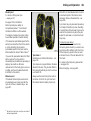
Belt tension ers
The sea t belts are fitted with belt tensioners.
The seat belts are pulled down at the
buckles on a front or rear impa ct above
a certa in severity . This tightens the belts.
Actuati on of belt tensioners
is indicated by illum ina tion of control
indica tor v, see next column.
If the belt tensioners are triggered, they
must b e replaced by a workshop.
Further inform ation – see page 53.
C ont rol indic ator v for belt tensioners
The function of the belt tensioners and
airbag sy stems is monitored electronica lly
and indicated by the c ontrol indicator v.
When the ignition is turned on, the control
indicator comes on for a pprox. 4 seconds.
If it does not come on, or if it does not go
out after 4 sec onds, or if it comes on while
driving, there is a fault in the belt tensioner
or airbag sy stems, see page 60.
The sy stems might not trigg er in the event
of an ac cident.
Deployment of the belt tensioners is
indicated by continuous illumination of v.
Seats, Interior
9 Warning
Have the cause of the fault eliminated
im med ia tely by a work shop.
Self-diagnosis integrated into the system
allows rapid fault identification.
Imp or tant
z Do not fit accessories not sp ecifically
released for y our v ehicle type or store
objec ts in the belt tensioner operating
area (in the area of the belt tensioners)
due to the risk of injury in the event the
belt tensioners a re triggered.
z Do not mak e any modifications to the
components of the belt tensioners, as
this will render the v ehicle unroadw orthy.
9 Warning
Incorrect handling (e.g. rem ov al or fitting
of seat b elts or belt buc kles) can trigger
the belt tensioners with risk of injury.
53
z The belt tensioner and airbag sy stem
control electronics can be found in the
centre console area. In order to av oid
malfunctions, do not store mag netic
objects in this a rea.
z We recom mend that you have the front
seats removed by a w orkshop.
z The belt tensioners trigger once only,
ind ic ated b y the illumination of the
control indicator v. H ave a workshop
replace triggered belt tensioners.
z When disp osing of the v ehicle, the
safety instructions given for this must
be ob served. Take the v ehicle to
a rec ycling company for disposal.
54
Seats, Interior
Using the belts
Fitting seat bel ts
Pull the belt out of the retractor and guide
it across the body , making certain that it is
not twisted.
Insert latch plate into buc kle. Backrest must
not be tilted too far ba ck as this would
affect the operation of the sea t belts;
recomm ended tilting angle approx . 25°.
The lap belt must be straight and lie snug ly
against the body. Tighten lap belt at
frequent intervals whilst driving by tugging
diagonal part of belt.
9 Warning
O n pregnant women in particular, the
lap belt must be positioned as low as
possible across the pelv is so as not to
put too much pressure on the abdomen.
Bulk y clothing prevents the belt from fitting
prop erly. The belt must not rest against
ha rd or fragile objects in the pockets of
your clothing (e.g. ballpoint pens, keys,
spectacles) because these could cause
injury. Do not place any objec ts (e.g.
ha ndb ags, mobile phones) b etween the
belt and your body.
Remov ing the belt
To remove the belt, depress the red
pushb utton on the b uc kle; the belt will
retrac t autom atically.
Seats, Interior
Child restraint systems 3
When using a child restraint sy stem, follow
the instructions for installation and use.
The c ountry in which y ou a re travelling
may not perm it the use of child restraint
systems on certain seats. Alw ays comply
with the local or na tional regulations.
Selecting the right system
Your child should travel fa cing backwa rd s
in the c ar for as long as possible. A child
has a very weak neck area and in the ev ent
of a n accident is less likely to suffer injury in
a rearward-facing, semi-lying position
than if seated upright.
9 Warning
Nev er carry child restraint sy stems on
your lap, risk of fatal injury.
Perm issib le options for fitt ing a chil d
sa fet y seat
Weight
and
age class 1)
0:
to 10 k g
and approx.
10 months
0+ :
to 13 k g
and approx.
2 years
I:
9 t o 18 kg
or approx.
8 months to
4 years
II:
15 to 25 kg
and approx.
3 to 7 y ears
III :
22 to 36 kg
and approx.
6 to 12 years
1)
On
the
front passenger seat
B1
55
B 1 = Limited, only with seat occupancy
recognition and Vauxhall child
restraint sy stem with transponders.
Move seat 3 to highest position.
Move front p assenger seat b ack
as far as possible.
Not e
z Children und er 12 years or und er 150 cm
tall should only trav el in an ap prop ria te
child sa fety sea t.
z When transporting c hildren, use the child
restra int system s suitable for the child’s
weight.
B1
z Check that the child restraint systems
ha ve been correctly installed – see
instructions provided with child restraint
sy stem.
z The covers of Vauxhall child restraint
sy stems can be wiped clea n.
B1
We recom mend th e u se of each system
un til the child rea ches the upp er w eight
limit.
z Do not stick any thing on the child
restra int system s and do not cover
them with a ny other materials.
z A child restraint sy stem which has been
subjected to stress in an accident must
be replaced.
z Secure or remov e child restraint sy stems
carried in the vehicle when not in use.
56
Seats, Interior
Exception:
Passenger sea t with seat occupancy
recognition system 3 . The seat occupancy
recognition system deactiva tes the front
and side airbags on the p assenger sid e if
the front passenger seat is unoccupied or a
Vauxhall child restraint system with
transponders 3 ha s been fitted to the front
passenger seat. S eat occupa ncy
recognition – see p age 60. Vauxhall child
restraint system w ith transponders 3 –
see page 61.
Examples of events triggering the front
airbag sy stem:
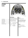
Airbag System
z seat occ upa ncy rec og nition 3,
Front airb ag
The front airbag system is identified by the
word AI RBAG on the steering wheel and
above the glov e c om partment.
z the control indicator for Va ux ha ll child
restraint systems y with transponders 3
in the courtesy light.
The front airbag system comprises:
z an airbag with inflator in the steering
wheel and a second one in the
instrum ent panel,
z the control elec tronics with impact
sensor,
z control indicator for airbag systems v in
instrum ent panel,
The front airb ag system will be trigg ered :
z depending on the severity of the
accident
z depending on the type of impact
z within the range shown in the illustration
z indep endently of the side airbag system.
z Impact against a non-y ielding obstacle:
the front airbags are trigg ered at low
vehicle speed.
z Impact against a yielding obstacle (such
as another vehicle): The front airba gs are
only triggered a t a higher vehicle speed.
Seats, Interior
When trigg ered , the front airbags inflate in
milliseconds and form a safety cushion for
driver and front passeng er. Forward
movement is checked and the risk of
injuries to the upper body a nd head
thereby substantially reduced.
No im pairment of view will occur, because
the a irb ags inflate and deflate so quickly
that it is often not ev en noticed in an
accident.
9 Warning
The front airbag sy stem provides
optimum p rotection when the seat,
back rest a nd head restraint are correctly
adjusted: Adjust the driver’s seat
according to the occupant’s height so
that when the driver is sitting upright, the
steering wheel is held in the a rea of its
upper sp ok es with the d riv er’s arms
slightly bent. The passenger seat should
be as far back as possible, with the
back rest upright (see pa ges 46, 47, 48).
Do not place the head, b od y, hands or
feet on the c ov ers of the airbag sy stems.
Do not place any objects in the area
in which the a irb ags inflate. Im portant
inform ation – see page 62.
57
9 Warnin g
The three-point seat belt must b e
correctly fitted – see pag e 54.
The front airbag sy stem will not be
triggered in the ev ent of
z
z
z
z
the ignition is switched off
minor frontal collisions
accidents in which the vehicle overturns
collisions involving a sid e or rear impac t
that is to say, if it w ould not be of benefit to
the oc cup ants.
58
Seats, Interior
9 Warning
Seat belts m ust therefore a lways be worn.
The front a irb ag system serv es to
supplement the three-point seat belts. If
you do not wea r your seat belt you risk
being seriously injured, or even thrown
from the vehic le, in the ev ent of an
accident.
In the event of an ac cident the belt helps
to keep you in the correct seating
position, so tha t the front airbag system
can provid e you with effective p rotection.
In addition, the front airb ag sy stem will not
be triggered for the front passenger in
versions with seat occupancy
recognition 3 if
z the front p assenger seat is unoccupied
z there is a prop erly fitted Va ux ha ll child
restraint system with transponders 3 .
Seat oc cup ancy recognition – see
page 60. Vauxhall child restraint system
with transponders 3 – see page 61.
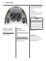
Side airb ags
The side a irb ag system is identified by the
word AIRBAG on the outb oa rd sides of the
seat back rests.
The side airbag sy stem will be triggered:
The side a irb ag system c om prises:
z within the range shown in the illustration
on the driver’s or front passenger side
z an airbag with inflator in the back of
the driver’s and front passenger seat
respectively ,
z the control electronics,
z the side impact sensors,
z control indicator for airb ag sy stems v in
instrument panel,
z seat occ upa ncy rec og nition 3,
z the control indicator for Va ux ha ll child
restraint systems y with transponders 3
in the courtesy light.
z depending on the sev erity of the accident
z depending on the ty pe of im pact
z independently of the front airbag system.
Seats, Interior
Ex cep tion:
Passenger seat with seat occupancy
recognition system 3 . The seat occupancy
recognition system deactivates the
passenger front and side airbags if the
passenger sea t is unoccupied or a Vauxhall
child restraint system with transponders 3
has b een fitted to the passenger seat. Seat
occupanc y recognition – see page 60.
Vaux hall child restraint system with
transponders 3 – see page 61.
59
9 Warnin g
There m ust be no objec ts in the area in
which the airbag inflates or in the area
between the seat ba cks and the v ehicle
body. Do not place the hands or arms
on the covers of the airbag system s.
Important informa tion – see page 62.
The three-point seat belt m ust alway s be
correctly fitted – see pag e 54.
The side airbags will not b e trig gered in the
event of
When deploy ed, the side a irb ag inflates
within m illiseconds and forms a safety
cushion for the driver or front pa ssenger
in the respective front door area. This
substantia lly reduces the risk of injury to
the upper body a nd pelv is in the event of
a side-on collision.
z the ignition is switched off
z frontal collisions
z accidents in which the vehicle overturns
z collisions involving a rear impact
z collisions involving a side impact outside
the passenger cell.
In ad dition, the sid e airbag sy stem will not
be triggered for the front passenger in
versions with seat occupancy
recognition 3 if
z the front passeng er seat is unoccupied
z there is a properly fitted Vauxhall child
restra int system with transponders 3.
Seat occupancy recognition – see
page 60. Vauxhall child restraint system
with transponders 3 – see page 61.
60
Seats, Interior
9 Warning
Hav e the cause of the fa ult eliminated
immediately by a workshop.
Self-diagnosis integrated into the sy stem
allow s rap id fault identification.
Cont rol indica tor v for airb ag systems
The function of the airbag sy stems is
monitored electronically together with the
seat occupancy detection 3 and the belt
tensioners. Their opera tional readiness is
indicated by control indicator v in the
instrument panel. When the ignition is
switched on, the control indica tor
illuminates for approx. 4 seconds. If it does
not illum inate, d oes not go out after
4 seconds or illum inates whilst driving,
there is a fault in the airbag sy stems, the
seat occupancy detection 3 or in the belt
tensioners, see also p age 52. The sy stems
may fail to trigger in the event of an
accident.
Dep loy ment of the airbags is ind icated by
continuous illumination of v.
Seat occupancy recogniti on 3
The seat occupancy recognition system
deactivates the passenger front and side
airbag s if the front pa ssenger seat is
unoccupied or a Vaux hall child restraint
system with tra nsponders 3 has been
fitted to the front passeng er seat.
C ontrol indicator y for seat occupa ncy
recognition is loc ated in the courtesy light.
If c ontrol indicator y illuminates for
app rox . 4 seconds when the ignition is
switched on, the vehicle is equip ped with
seat occupancy recognition – see pa ge 61,
Fig. 16409 S.
If a Vaux ha ll child restraint system with
transponders 3 is fitted, the control
indicator y illuminates permanently after
the ignition is switched on as soon as the
system ha s d etec ted the child restraint
system. Only then may the child restraint
system with tra nsponders 3 be used on
the passenger seat.
Seats, Interior
61
9 Warning
O nly Vauxhall child restra int sy stems with
transp onders 3 can be fitted on the front
passenger seats. Use of systems without
transp onders poses a risk of fatal injury.
Vauxhall c hild restraint system s w ith
tra nsponders 3 can be identified by a
sticker or badg e.
Seat occupancy recognition in a vehicle is
also indicated by a sticker on the front
passenger seat – see Fig. 12106 A.
Vauxhall child restraint sy stems with
transponders 3 are autom atically
detected if corrected fitted to the front
passenger seat. The front and side airbag
systems for the front passenger sea t are
deactivated when these child restraint
systems are used. Pay attention to the seat
occupancy recognition 3 control indica tor
– see pa ge 60.
Control i nd icator y for Va uxhall child
restra int systems w ith transponders 3
The presenc e of a Vauxhall c hild restraint
sy stem with transponders 3 is ind icated
after the ig nition has been switched on
by permanent illumination of the control
indica tor y in the courtesy light, as soon
as the seat occupa ncy recognition sy stem
ha s d etec ted the child restraint sy stem.
If the control indicator d oes not illuminate
during driving, the front and sid e airba gs
for the front seat pa ssenger are not
deactivated and there is a risk of fatal
injury to the c hild. Have a work shop
elimina te the cause of the fault.
If the child restraint sy stem is not correctly
insta lled or the transp onders are defective,
the indic ator lig ht w ill fla sh. C heck for
correc t child restraint sy stem installation.
For installation of child restraint sy stem
with transponders 3 – see instruc tions
provided with child restraint system.
62
Seats, Interior
If the control indicator flashes when the
child restraint system w ith transpond ers 3
is correctly fitted, there is a fault and a
danger to the child. Have the ca use of
the fault eliminated by a work shop.
Imp or tant
If no Vauxhall child restraint system with
transponders 3 is fitted, the control
indicator m ust not illuminate or flash a s the
passenger airb ag systems would not
deploy. H ave the cause of the fault
elim inated by a workshop.
z Do not place any objects between
the airb ag systems and the vehicle
occupants; danger of injury.
9 Warning
If the Vauxhall child restraint system with
transp onders 3 has been fitted according
to the instructions, the control indicator for
Vauxhall restraint systems with
transp onders must illuminate in the
courtesy light when the ignition is switched
on.
If the control indicator does not illumina te
during driving, the front passenger airbag
systems are not d eactivated and there is
a risk of fatal injury . Have a workshop
eliminate the c ause of the fa ult.
z Due to risk of injury when the airbag s
deploy, a ccessories and objects should
not be placed within the expansion
range of the airbag sy stems.
9 Warning
Never carry child restraint systems or
other objects on y our la p - risk of fatal
injury .
z The airb ag systems and b elt tensioner
control electronics can be found in the
centre console area . In order to avoid
malfunctions, d o not store magnetic
objec ts in this area.
z Do not stic k anything on the steering
wheel, instrum ent panel, seat ba ckrests
or roof frame in the vicinity of the
airbags, or on the front pa ssenger’s seat
cushion, or c ov er any of those areas with
other m aterials.
z Use only a dry cloth or interior cleaner
to clean the steering wheel, instrument
panel, seat back rests and seat cushion
of the front passenger seat. Do not use
any agg ressive cleaning agents.
z Only protective covers which are
approved for your vehicle with side
airbag m ay be fitted on the seats.
When fitting the protective covers,
make sure that the a irb ag units on
the outboard sides of the seat
backrests are not covered.
z The airbag sy stems are triggered
ind epend ently of one another
depending on the sev erity of the
accident and type of impact.
z Each a irb ag deploys once only. Have
a workshop replace deployed airbags
immediately.
z The speeds, directions of movement and
deformation properties of the vehic les,
and the p roperties of the obstacle
conc erned, determ ine the severity of the
accident and triggering of the airbags.
The degree of dama ge to y our vehicle
and the resulting repair costs alone are
not indica tiv e that the criteria for
trig gering of the airb ags were met.
Seats, Interior
z Do not p erform any a lterations on the
com ponents of the airbag sy stem, as this
would render the vehic le unroadworthy .
9 Warning
The systems can be triggered ab ruptly
and cause injury if they are handled
im properly.
z We recom mend entrusting rem ov al of
the steering w heel, the instrument panel,
all panelling parts and the seats to a
work shop.
z When disposing of the vehicle, the safety
instruc tions given for this must be
ob served. Tak e the vehicle to a recycling
com pany for disposa l.
63
z In v ehicles with seat occ upa ncy
rec og nition 3 persons w eighing less than
35 kg must not be transported . This d oes
not apply to children that are being
transp orted in child restraint systems
with transp onders 3.
z When using a Vauxhall c hild restraint
sy stem with transponders 3 on the front
passeng er seat, in order to prevent
malfunctions, no objects (e. g. pla stic
sheet, stickers or heated mats) may be
placed und er the child restraint sy stem.
z In v ehicles with seat occ upa ncy
rec og nition 3, do not place any heavy
objec ts on the front passenger seat
otherwise the airbag system s for the
front passenger seat may be triggered in
the event of an accident.
9 Warnin g
z In v ehicles with seat occ upa ncy
rec og nition 3, to prev ent malfunctions
do not use protective cov ers or seat
cushions on the front passeng er seat.
Child restraint system s as well as other
objects must never b e carried on the
lap of passeng ers; risk of fatal injury. I f
carried in this way , child restraint systems
with transpond ers 3 in vehicles with seat
occup ancy recognition 3 could lead to
front pa ssenger airbag sy stem s not being
trigg ered in the ev ent of an accident.
64
Seats, Interior
Vehicles with sea t occupancy recognition
can be identified b y control indicator y in
the courtesy light. If control indicator y
illuminates for approx. 4 seconds when
the ignition is switched on, the vehicle is
equipped with seat occupancy recognition
– see page 60.
S eat occupancy recognition in a vehicle
is also ind icated by a sticker on the front
passenger seat – see p age Fig. 12106 A.
Use of child restrai nt systems 3 of t he
front p assenger sea t of vehicl es wi thout
sea t occupa ncy recogni tion 3
9 Warning
No child restraint system 3 may be
installed on front passenger seat.
Da ng er to life.
Seat occupancy recognition 3 – see
page 60.
Use of a child restrai nt system 3 on t he
front pa ssenger seat of a v ehi cle wit h sea t
occupancy recogniti on 3
9 Warning
O nly Vauxhall child restra int sy stems with
transp onders 3 can be fitted on the front
passenger seats. Use of systems without
transp onders poses a risk of fatal injury.
The seat occupancy recognition system
detects Vauxhall child restraint sy stems
with transponders 3 and d eactiva tes the
front and side a irb ags for the front
passenger seat. S eat occupa ncy
recognition – see p age 60.
Vauxhall child restraint systems with
transponders 3 can b e identified by a
sticker or badge.
Seats, Interior
65
The maximum power c onsumption of
electrical ac cessories m ust not ex ceed
120 w atts.
Do not connect any current-delivering
acc essories, e.g. electrical charging
devices or b atteries.
Electrical ac cessories connected to the
socket must c om ply with the electroma gnetic compa tib ility requirem ents laid
down in DIN VDE 40 839, otherwise vehicle
ma lfunctions m ay occur.
Cigarette lighter 3
Accessory soc ket 3
The cigarette lig hter is in the centre console.
The accessory socket is in the centre
console.
Press in cigarette lighter with ignition
switched on. S witches off autom atically
when elem ent is glowing. Withdraw
cigarette lighter.
The accessory socket or cigarette lighter
socket can be used to c onnect electrical
accessories. The socket is op erational
when the ignition is switched on. Use of the
socket disc harges the battery if the engine
is not running. Do not damage the socket
by using unsuitable plug s.
66
Seats, Interior
Ashtray
3
To be used only for ash and not for
combustible rubbish.
9 Warning
Failure to ob serve these descriptions
can lead to injuries which ma y be fatal.
Vehicle passengers should be informed
according ly .
O pen the ashtray cover to the resista nce
point.
To empty , open the ashtra y cover fully
bey ond its resistance p oint, causing the
insert to lift. Grip both sides of the ashtra y
insert a nd pull upwards.
To enlarge the stora ge c om partment
remove the ashtray com pletely.
Sto wage compartments
St owage com partm ent behind the sea ts
The compartment is only suitable for
stowing light objects. Max imum load:
10 kg.
9 Warnin g
Secure objects to prevent them from
falling out a nd causing injury while
driving.
The load m ust not hinder pedal, ha nd
brake or gea rshift operation or impair
the driver in any w ay.
Seats, Interior
67
Su n visors
Use the sun v isor to protect from glare by
pulling it d ow n and swivelling it to the side.
Glov e com part ment
To open, pull hand le upwards.
Ca n be lock ed w ith the vehicle key.
O n the inside of the glov e c om partment
cover there is a pen holder.
The g lov e com partment should be closed
whilst driving .
Coin holder 3
In the centre console.
68
In struments, Controls
Instruments,
Controls
Control indic ators
Control indicators .... ..... .... ..... .... .... ..... .
Instrument display ... ..... .... ..... .... .... ..... .
Information display . ..... .... ..... .... .... ..... .
Warning buzzers.. .... ..... .... ..... .... .... ..... .
Wind screen wiper .... ..... .... ..... .... .... ..... .
Wind screen wash system . ..... .... .... ..... .
68
74
76
86
87
87
The control indica tors described here are
not p resent in all vehicles. The description
applies to all instrum ent versions.
The control indica tor colours mean:
z Red
z Y ellow
Danger, important rem ind er,
Warning , note, fault,
z Green
z Blue
O n confirmation,
O n confirmation.
X
Seat belt 3
C ontrol indicator illuminates red.
This c om es on after turning on the ignition
(with warning tone) until the seat belt is
app lied. Ap ply seat belt – see page 54.
>
Fog lig ht s 3
C ontrol indicator illuminates green.
It is illuminated when the fog lights are on –
see page 89.
In struments, Controls
69
Z
Exhaust emi ssion
C ontrol indicator illuminates or flashes
yellow.
It illuminates w hen the ignition is switched
on and g oes out shortly after the engine
starts.
Illuminates when the eng ine is running
Fault in emission c ontrol system. The
permitted emissions may be ex ceeded.
C ontact a workshop immediately.
A
Eng ine electronics, transmission
elec tronics, imm obilizer , diesel fuel filter 3
Control indicator illum inates or flashes
yellow.
It illuminates for a few seconds when the
ignition is switched on.
Illuminates when the engine is running
Fault in engine or g earbox electronic
system. Electronics have sw itc hed on
emergency running prog ra mme fuel
consump tion ma y be increased and
the v ehicle’ s driv eability reduced,
see page 115. C onta ct a workshop
immediately .
For vehicles with diesel engine, the d iesel
fuel filter m ay need to be drained of water,
see p age 181.
Flashes when the ignition is on
Fault in the electronic immobilizer system;
the engine cannot be started, see page 21.
If it flashes when the engine is running:
Fault which could lead to damag e to the
cataly tic conv erter, see pa ge 115. Contact
a work shop imm ediately.
70
In struments, Controls
1. Move out of the flow of traffic a s quickly
as possible, without im peding other
vehicles.
2. Dep ress clutch.
3. Move gearshift lev er to neutral, or with
Easytronic 3, place selector lever in N.
4. Switch off ignition.
9 Warnin g
When the eng ine is off, considerably
more force is needed to brake and steer.
Do not remove key until v ehicle has com e
to a standstill, otherw ise the steering
colum n lock could engage unexpectedly .
v
Airb ag systems 3 , Bel t tensi oners
Control indicator illum inates red.
I
Engine oil p ressure
Control indica tor illuminates red.
Illuminates when the engine is running
Fault in the airbag or belt tensioner
systems, see pages 52, 60.
It illum ina tes when the ignition is switched
on a nd goes out shortly after the engine
starts.
!
Illum inates when the engine is running
Engine lub ric ation may be interrupted . This
may result in dam age to the engine and/or
lock ing of the drive wheels:
Preheating system active, switches on only
if outside temperature is low.
C ontact a workshop.
Prehea ting system 3
C ontrol indicator illuminates yellow .
In struments, Controls
71
T
Easytronic winter pr ogramm e 3
S ymbol illuminates in gear display w ith
Winter programm e engaged.
Easy tronic, see page 102.
r
Fog tai l light
C ontrol indicator illuminates yellow .
It is illuminated when the rear fog lig hts are
on, see pag e 89.
O
Turn signal l ights
Control indicator flashes g reen.
C
The c orresponding control indicator
flashes on the side of the direction
indicators selected.
It is illuminated when m ain beam is on and
during headlight flash, see pages 10, 89.
Both control indicators flash with the
hazard warning lig hts on.
Rapid fla shing: failure of a direction
indicator light or associated fuse.
Change bulbs, see page 152. Fuses,
see page 148.
Main beam
Control indica tor illuminates blue.
j
Easytronic 3 , st art engine
Control indica tor illuminates y ellow.
It illum ina tes if the foot brake is not
op erated. The indicator goes off as soon as
the foot brake is operated. The engine
can only be sta rted with the foot b ra ke
op erated, see page 103.
p
Alt erna tor
C ontrol indicator illuminates red.
It illuminates w hen the ignition is switched
on and g oes out shortly after the engine
starts.
Illuminates when the eng ine is running
Stop, switch off engine. Battery is not
charging. C ontact a work shop immediately.
72
In struments, Controls
S
Engine oil level 3
C ontrol indicator illuminates yellow .
The engine oil level is checked
automatically.
Illuminates when the eng ine is running
Eng ine oil lev el too low. Check engine oil
level and top up eng ine oil if necessary,
see page 179.
EPS 1)
Electric p ower steering
C ontrol indicator illuminates yellow .
R
Brak e system , clut ch system
Control indicator illuminates or flashes red.
It illum ina tes a fter the ig nition is turned on,
when the hand brake is applied or if the
brake or clutch fluid lev el is too low. For
further information see pages 123, 183.
9 Warning
If it Illuminates when the hand brake is
not ap plied. Stop driving a nd conta ct a
work shop imm ediately. We recomm end
your Vauxhall Authorised Repairer.
On vehicles with Ea sy tronic 3 control
indica tor R flashes for a few seconds
after the ig nition is sw itc hed off if the
ha nd brake has not b een applied.
Fault in electric al power steering. Vehicle
can still be driven, but grea ter force is
required for steering. Contact a w ork shop
imm ediately.
u
Anti-lock Brak e S ystem 3
Control indica tor illuminates red.
Illum inates while driving
Fault in anti-lock brak e system , see
page 125.
1)
EPS = E lectric P ow er Steering .
In struments, Controls
v
Elec tronic St abili ty Progra m (ES P® P lu s ) 3
Control indicator flashes or illuminates
yellow.
Y
Fuel level
Control indica tor illuminates or flashes
yellow.
Flashing during driving
Sy stem actively engaged, see page 118.
lig hts
Low fuel level, fuel gauge in reserve area.
Illuminates while driving
Fault in electronic stability programme, see
page 118.
Flashing
Fuel supply ex hausted, refuel im med ia tely.
Nev er let the tank run dry !
Erratic fuel supply can cause cataly tic
conv erter to ov erheat, see page 114.
Diesel eng ines: If the tank is run dry, bleed
the fuel system as described on page 132.
y
Seat occupancy recogniti on 3
see pages 60, 61.
73
74
In struments, Controls
Instrum ent display
Tachom eter
Indicates engine speed.
Warning zone: M aximum p ermissible
engine sp eed ex ceeded ; danger to engine.
Sp eedometer
Speed display.
Mileage displ ay
If the ignition is off the m ileage is displa yed
for a pprox. 15 seconds by b riefly pressing
the reset knob.
Top line:
Trip odometer
C ool ant temp era ture display
Pointer in
= Eng ine opera ting
zone at left
temperature not
yet reached
Display of miles covered since reset.
Pointer
between
the zones
= N orma l operating
temperature
To reset, hold the reset knob dep ressed for
a few seconds with the ignition on.
Pointer in
red zone
= Temperature too high:
S top vehicle and switch
off engine. Danger to
eng ine. C heck coolant
level im med ia tely, see
pag e 182.
Bottom line:
Odometer
Records the m iles counted.
For physical reasons, the engine
temperature gauge shows the coolant
temperature only if the coolant level is
adequate.
During operation the system is pressurised.
The temperature may therefore rise briefly
to over 100 °C .
In struments, Controls
Fuel g auge
Pointer in red
warning zone
or Y illum inated
Pointer in red
warning zone
or Y flashing
= Reserve level
Tr ansm issi on display 3
Display of current gear or mode with
Easytronic 3:
R
N
Reverse gear.
Neutral.
Never run the tank dry !
A
1-5
Diesel engines: If the tank is run d ry , bleed
the fuel sy stem as described on page 132.
Automatic mode on Easytronic .
Manua l mode, current gear on
Easytronic.
Easytronic 3 – see p age 102.
= Refuel immediately
– see page 113
Because of the fuel remaining in the ta nk ,
the a mount of fuel required to fill the tank
may be less tha n the specified tank
capac ity .
Serv ice Display 3
When the ind ic ator in the display of the
odometer com es on, mak e a service
app ointment with a workshop as soon
as possible.
Maintenance, inspection system –
see page 177.
75
76
In struments, Controls
For Infotainment sy stem see Infotainm ent
system guid e.
Ü
Board Computer
BC 1
12:01
17,0 °C
FM 3 90,6 MHz
REG
AS
RDS
All values
BC 2
Timer
19,5° 19:36
1
257.0
Ø 40
8
Ø
TP
Information display
Tripl e inform ation d isp lay 3
Display of time, outside tempera ture and
date/Infotainment system (when it is on).
When the ignition is off, the time, date and
outside tem perature can be made to
appear for approx. 15 seconds by briefly
pressing one of the two buttons adjacent
to the d isplay .
Display F in the display indicates a fa ult.
Hav e the cause eliminated by a workshop.
6.0
7.0
miles
mph
gal
miles/ gal
Graphica l Informa tion Display 3
Display of time, outside temp erature a nd
date/Infotainment sy stem (when it is on).
The information that is d isplay ed depend s
on the Infota inm ent system c onfiguration.
Some information app ears in the disp lay in
an abbreviated form.
Display F in the displa y indicates a fault.
Hav e the ca use eliminated b y a workshop .
In struments, Controls
77
9 Warnin g
8:56
-5 ,5° C
07.04.2004
Caution: The road surface may already
be icy even though the d isplay indicates
a few deg rees ab ov e 0 °C .
:
Slippery road
-2, 5°C
OK
Outside temperature
A fall in temperature is indica ted
immediately and a rise in temp erature
after a time delay .
If the ex ternal tem perature falls to 3 °C ,
to warn of ice on the road the symbol :
appears in the Triple Info display . When
the temperature climbs, the symbol :
goes out abov e 5 °C .
In vehicles with graphical inform ation
display 3, a warning message is shown
in the display a s a warning for icy road
surfaces. No message is displa yed at
temperatures below -5 °C.
78
In struments, Controls
8:56
5 ,5 °C
07.04.2004
Triple info rmation display
Set d ate and ti me
Infotainment system off: press Ö and ; next
to the display as follows:
Press Ö for ap prox . 2 seconds:
Day fla shes
;: Set day
Ö : Month fla shes
;: Set month
Ö : Year flashes
;: Set year
Ö : Hours flash
;: Set hours
Ö : Minutes flash
;: Set minutes
Ö : Clock is started.
Correcting time 3
Some RDS transmitters do not send a
correct time sig nal. If the incorrect time is
display ed on frequent occasions,
deactiv ate automatic tim e
sy nchronisation 3 – see nex t colum n, and
set the time manually.
Deactivating/ac tiv ating autom atic time
synchronisation: Infota inm ent system off,
press Ö and ; next to the display:
The automatic setting is indicated by } in
the display.
Press Ö and hold down for approx.
3 seconds until } flashes in display 3
and text " RDS TIME" ap pears (years
flash during this time),
Hold down Ö for a pprox. 2 sec., cloc k
display is now in setting m ode,
Press Ö twice (until year flashes),
Press ; - display shows:
RDS TIME 0 = Off
Press ; - display shows:
RDS TIME 1 = On
Press Ö three tim es.
In struments, Controls
FM AS
[TP]
1
19,5°
REG
C Din
79
MP3
90.6 MHz
19: 36
Graphical information display 3,
Selecting functions
The g ra phic al information display depicts
func tions and their m enus.
These functions are m arked or exec uted in
the m enu display v ia the four-way button,
the m ulti-function k nob 3 on the
Infotainm ent Sy stem or buttons 3 on the
steering wheel.
To select w ith four-wa y but ton:
Select menu items via menus and with
the buttons/four-way button of the
Infotainment sy stem.
Selecti on with the mul ti-function k nob 3:
Turn
Mark ing of menu options or c om mands,
selection of function ranges,
Press
S elec tion of ma rk ing, confirm ation of
comm ands.
To exit a m enu, turn the m ulti-func tion
button left or right to Return or M ain
and select.
6
80
In struments, Controls
7
FM AS
[TP]
REG
C Din
MP3
Settings
Time, Date
19,5° 19:36
19:36
Language
1
90.6 MHz
Units
10 . 07 . 2004
Contrast
Day / Night
19,5°
Selection using b uttons 3 on steeri ng
wheel
Select menu options v ia menus and w ith
the b uttons.
19: 36
For each functional area there is a main
page (Main), which is selected at the top
edge of the d isplay (not with the
Infotainment sy stem CD 30 or the Mobile
Phone Portal):
z
z
z
z
Audio
Na vigation 3
Telephone 3
Trip comp uter 3.
Function areas audio, nav ig ation 3 and
telep hone 3 – see Infotainment System
Instructions.
6 Ign. logic
System settings
The settings are accessed via the Setting s
menu.
Press the Ma in button 3 (not found on all
Infotainment sy stems) on the Infotainm ent
system (c all up main display).
Press the S ett ings button on the
Infotainment system. For I nfotainment
system CD 30, no menu m ay b e selected.
The Settings m enu is displa yed.
In struments, Controls
7 Time, Date
Time
Date
19,5° 19:36
19:36
10 . 07 . 2004
6 Synchron. clock automatical.
Correcting time 3
Some RDS transmitters 1) do not send
correct time sig nals. If the incorrect time
is frequently displayed, deactiva te
autom atic time sy nchronisation 3 and set
the time manually.
7
Settings
81
19,5° 19:36
Time, Date
To correct tim e with the help of RDS, select
menu item Synchron. clock autom atica l.
from the Time, Da te menu.
Language
Deutsch
Units
English
Contrast
Español
The box in front of Synchron. clock
automat ical. will be ticked –
see Fig. 16713 T.
Day / Night
...
6 Ign. logic
Setti ng the date and time 3
Select menu item Time, Dat e, from the
Setti ng s menu.
Languag e selection
Y ou can select the display language for
some functions.
The m enu for Time, Date is displayed.
Select the menu items required:
S elec t menu item Language from the
Sett ings menu.
Make the desired setting.
The available languages are displayed.
6
1)
RDS = Rad io D ata S ys tem.
82
In struments, Controls
7
13 Languages
19,5° 19:36
X Deutsch
7 Settings
Language
Español
Units
Nederlands
Contrast
F rançais
Day / Night
Italiano
6 Ign. logic
Selections are indicated by a 6 in front of
the m enu item .
In systems with voice output 3, w hen the
language setting of the displa y is changed
the system will ask whether the
announcement language should also be
changed – see Infotainment system
instructions.
7 Contrast
19,5° 19:36
Time, Date
English
Select the desired language.
19,5° 19:36
~
|
|
|
Europe-SI
Japan
12
Great Britain
USA
Setting unit s of m easur e
You can select which units of measure are
to be used .
Ad just contrast
S elec t menu item Cont rast from the
Sett ings menu.
Select menu item U ni ts from the S et tings
menu.
The menu for Contr ast is disp layed .
The ava ilab le units are display ed.
Select the desired unit.
Selections are indicated by a o in front of
the menu item.
C onfirm the required setting .
In struments, Controls
Setti ng displa y mod e 3
The d isplay can be adap ted to light
conditions: b la ck text on a light
back ground or w hite tex t on a dark
back ground.
Select menu item Day / N ight from the
Setti ng s menu.
The options are display ed.
Autom atic: adapted based on vehicle
lighting .
Alw ays da y design: Black text on light
back ground.
Alw ays night desi gn: White text on dark
back ground.
Selections are indicated by a o in front of
the m enu item .
Ig ni tion logic 3
See Infotainment sy stem instructions.
Ü
Board Computer
BC 1
19,5° 19:36
All values
BC 2
Timer
83
1
257.0
Ø 40
8
6.0
Ø 31.0
Range
miles
mph
Inst. Consump.
Aver. Consump.
257 miles
30.0 miles/gal
31.0 miles/gal
gal
miles/ gal
Graphic al information display 3,
Trip computer 3
The trip computers provide information on
driving data, which is continually recorded
and ev alua ted electronically.
The on-board computer main page gives
information on range, momentary
consumption and average consumption 3.
To display the other trip computer d riv ing
information, press BC button on
Infotainment sy stem 3 or select trip
computer menu on disp la y.
For vehicles with Infotainm ent Sy stem
CD 30 3 and steering wheel remove
control 3 , the left steering wheel buttons
only operate the trip c om puter.
19,5°
19: 36
Ra ng e
Range is calculated from current fuel tank
content and instantaneous consumption.
The display shows av erage values.
After refuelling, the vehicle updates the
range automatically a fter a brief delay .
84
In struments, Controls
Instantaneous consumption
Display changes depending on speed:
Display in gal/h
Display in mpg
Range
3 0m iles
OK
If less than 30 miles (50 k m) can be driven
with the fuel rema ining in the tank, the
warning "Range" a ppears on the d isplay .
If less than 20 miles (30 k m) can be driven
with the fuel rema ining in the tank, the
warning "Please refuel! " 3 appears on the
display.
Acknowled ge the menu item as desc rib ed
on page 79.
below 8 mph
(13 k m/h).
above 8 mph
(13 k m/h).
Di st ance trav ell ed
Display of miles travelled. The
measurement can be reset to zero a t
any time and restarted, see "Reset".
Average speed
Calculation of avera ge speed. The
measurement can be reset to zero a t any
tim e a nd restarted, see "Reset" .
Stoppages in the journey with the ignition
off are not includ ed in the calculations.
Effec tive consumpt ion
Display of fuel used. The m easurement can
be reset to zero at any time and restarted,
see "Reset".
Av era ge consum ption
C alcula tion of av erage consump tion. The
measurement c an be reset to zero at any
time and restarted, see "Reset".
In struments, Controls
Ü
Board Computer
BC 1
19,5° 19:36
All values
BC 2
Timer
257.0
40
1
Ø
8
6.0
Ø 31.0
19,5° 19:36
miles
mph
gal
miles/ gal
Distance tra velled,
Av erage speed,
Effective consump tion,
Av erage consump tion.
Select BC 1 or BC 2 from the trip computer
menu.
Ø
257.0
40
6.0
Ø 31.0
Ü Reset BC 1
19,5° 19:36
All values
All values
Reset : Reset t rip com puter informa tion
The following trip computer information
can be reset (restart mea surem ents):
z
z
z
z
Ü Reset BC 1
85
m iles
m ph
gal
m iles/gal
The information of both trip computers can
be reset separately a nd therefore provides
a facility for evaluating information over
different time periods.
Select the desired trip computer information.
The value for the selected function will be
reset and recalculated .
Ø
257.0
40
6.0
Ø 31.0
m iles
m ph
gal
m iles/gal
To reset all information of a trip computer,
select menu item Al l val ues.
After resetting , "- - -" is displayed with the
trip comp uter informa tion selected . The
recalculated v alues are displa yed after
a brief delay.
I nt err up tion of pow er supp ly
If the power supp ly has been interrupted or
if the battery voltage ha s dropped too low,
the values stored in the trip computer w ill
be lost.
86
In struments, Controls
The stop watch information to be displayed
can be selected v ia menu O ptions 3 :
Ü Board Computer
19,5° 19:36
BC 1
BC 2
00:00:00
Timer
Start
Reset
Options
Stop wat ch
Select menu item Timer from the Board
Com puter menu.
The Tim er menu is displayed.
To start, selec t menu item St art.
To reset, selec t menu item Reset .
Dr iving Ti me excl. S tops
Measurement of the time the v ehicle is in
motion. Stationary time is not included.
Dr iving Ti me incl. S tops
Measurement of the time the v ehicle is in
motion. The time the v ehicle is stationary
with the key in the starter sw itc h is
included.
Tr avel Time
Measurement of the time from manual
activation via Sta rt to manual deactivation
via Reset .
Warning buzzers
When starting the engine or whilst driving:
z if seat belt is not fastened 3,
z up on operation of Retractab le steel roof
or boot lid if the hand brake is not
applied ,
z up on operation of the Retra ctable steel
roof if the roof lock is not released ,
z up on operation of the Retra ctable steel
roof if lug gage com partment partition is
not folded bac k,
z when sta rting off if the Retrac ta ble steel
roof is not completely op en or closed,
z when starting off if the boot lid is not
completely closed,
z for Easytronic 3 - if A, M or R is selected
while the engine is running and the
driver’ s door is opened but the foot
brake is not d epressed.
When the vehicle is parked and the driv er’s
door is opened:
z with the key in the ignition,
z with parking lights or dipped beam
switched on,
z if the turn signal stalk is engaged .
In struments, Controls
87
Adjustab le w ipe interva l 3
Setting wip er interva l to a value between
2 and 15 sec onds:
Stalk to timed interv al wipe $ ,
stalk to §,
wait for desired interval,
stalk back to tim ed interv al wipe $ .
The interval tim e selected rema ins stored
until it is nex t changed or until the ignition
is turned off.
After turning on the ignition and setting the
lever to $ , the interval is set to 7 seconds.
Windscreen wiper
Win dscreen wash system
To activate, m ov e stalk b riefly up.
To activa te, pull stalk on steering wheel.
§
$
%
&
The wiper w ill swipe for a few strok es.
=
=
=
=
off
adjusta ble timed interv al wipe
slow
fast
88
Ligh ting
Lighting
Vehicles with d aytime running lights 3:
With the ignition on and the light switch
on 7 , dipped beam w ithout instrument
illumination is on.
The daytime running lights sw itc h off
when the ignition is switched off.
Follow the regula tions of the country in
which you are driving w hen using da ytime
running lig hts and fog lights 3.
Driving ab road – see pag e 91.
Ex terior lights .. ..... .... ..... .... ..... .... .... ..... .
Main beam, headlight flash . .... .... ..... .
Turn signal lights . .... ..... .... ..... .... .... ..... .
Reversing lights.... .... ..... .... ..... .... .... ..... .
Fog lights > 3 ..... .... ..... .... ..... .... .... ..... .
Fog tail light r .... .... ..... .... ..... .... .... ..... .
Haza rd warning lights.. .... ..... .... .... ..... .
Headlight range adjustment ? .... ..... .
Door-to-door light function 3... .... ..... .
Instrument illum ination k ..... .... .... ..... .
Information display illumination 3.... .
Courtesy lig ht 0.. .... ..... .... ..... .... .... ..... .
Battery discharge p rotection 3 .... ..... .
Headlights w hen driving abroad . ..... .
88
89
89
89
89
89
90
90
90
91
91
91
91
91
Exterior lights
Turn light switch:
7
8
9
=
=
=
Off
Park ing lights
Dip ped beam
or main bea m
In positions 8 a nd 9, the tail lights
and num ber p late lights are also on.
If the ignition is switched off with the
dipped bea m or main b eam on, the
parking lights illuminate 3.
Lightin g
Main beam, headlight flash
Turn signal lights
Fog lights > 3
To switch from dipped to main b eam, press
stalk forwards
To activate, press sta lk up or down.
On
=
Stalk up
Stalk down
O ff
=
To switch to dipped beam, p ress stalk
forwards again.
To activate the headlight flash, pull stalk
towards the steering wheel. Main b eam is
enga ged for the duration of a ctivation.
When the main bea m or head lig ht flash
is activated, the blue control indicator C
lights.
=
=
Turn signal light right
Turn signal light left
If the stalk is moved pa st the resistance
point, the turn signal lig ht remains on.
When the steering wheel moves ba ck
tow ard the straight-ahead position,
the turn signal light is automatically
deactiv ated.
Brief flash: press stalk to perceptible
resistance and release.
Reversing lights
Come on when reverse gear is engaged
and ignition is switched on.
89
p ress >, > lights in
instrum ent panel
p ress > a gain or sw itc h off
ig nition or light.
The fog lights can only be switched on
when both the ignition and lights a re on.
Fog tail light
On
=
O ff
=
r
p ress r, r lights in
instrum ent panel
p ress r again or switch off
ig nition or light.
The fog tail light can only be switched on
both the ignition and dipped beam/park ing
lights a re on.
90
Ligh ting
Hazard warning lights
Headlight ran ge adjustment ?
To activate, press button ¨, to deactivate
press button ¨ aga in.
Ad just head lig ht ra nge to the vehicle
loa d with dipped beam switched on:
turn adjuster wheel to d esired position.
To aid location of the pushbutton, the red
surface is illum ina ted when the ignition
switched on. When the button is p ressed,
its c ontrol ind ic ator flashes in time with the
hazard warning lig hts.
Correct ad justment of the headlight rang e
reduces d azzle for other roa d users.
Driv er’s seat occ upied
Sea ts occupied
Sea ts occupied and
full load in lugg age
compartment
Position 3 is not used.
=
=
=
0
1
2
Do or-to-door light fun ction
3
As d oor-to-door lig hting, the dipped beam
illuminates for approx. 30 sec onds after
leaving the vehicle and c losing the driver’s
door.
To act ivat e
1. Switch off ignition.
2. Remov e ignition key.
3. Open driver’ s door.
4. Pull turn signa l stalk toward steering
wheel.
5. Close driver’s door.
If the d riv er’s d oor is left op en, the lights will
go out after two minutes.
The lights go out im med ia tely if the ignition
key is inserted or the turn signal stalk on the
steering wheel is pulled aga in.
Lightin g
91
Battery discharge protection 3
Some consumers suc h as the interior lighting
switch themselves off after approx. 30
minutes if the ignition is off in order to
protect the battery charge.
Light covers
The inside of the light covers may b riefly
mist up under unfavourable wet/cold
weather conditions, during heavy rain or
after the vehicle has been wa shed . The
misting disappea rs of its own accord after
a short time, but can be accelerated by
switching on the lights.
Instrum ent illumination
k
Com es on with ex terior driving lights.
Brightness c an be adjusted with adjuster
wheel.
Information display illumination
3
Comes on when the ignition or Infotainment
system is on. Brig htness can be adjusted
with adjuster wheel.
Courtesy light 0
Headlights when driving abroad
Automat ic interior li ght
Ac tiv ates automatically when a d oor is
op ened .
The asy mmetrica l dipped beam increa ses
the field of vision on the passenger side of
the lane.
Goes off automa tic ally after a delay 3
when the d oors are closed or imm ediately
when the ig nition is sw itched on 3.
This causes g la re for oncom ing traffic if the
vehicle is driven in countries where traffic
drives on the opposite side of the road.
Front c ourtesy light
Manua l operation from inside with doors
closed:
To avoid d azzle, have a workshop convert
the headlights.
On
Off
=
=
Press lig ht switch 0
Press lig ht switch 0 again.
Lugg age comp artment 3
Comes on when the boot lid/tailgate is
op ened .
92
In fotain men t system
Infotainment system
Radio reception
3
Car radio recep tion differs from dom estic
ra dio reception:
As the vehicle antenna is rela tiv ely near
the ground , the broa dcasting companies
cannot g uarantee the sa me quality of
reception a s obtained with a d om estic
ra dio using an ov erhead antenna.
z Changes in distance from the transm itter,
z multi-path rec eption due to reflection
and
z sha dowing
may c ause hissing , noise, distortion or loss
of reception a ltogether.
Radio reception 3 .... ..... .... ..... .... .... ..... .
Remote control on steering wheel 3 . .
AUX input 3 .... ..... .... ..... .... ..... .... .... ..... .
Infotainm ent system 3 . .... ..... .... .... ..... .
Mobile telephones a nd
radio eq uipm ent (CB) 3 ..... .... .... ..... .
92
92
93
93
Remo te control o n steering
wheel 3
93
Further information – see page 79 and the
relevant operating instructions.
The functions of the infotainm ent system 3
and the informa tion display can be
operated on the steering wheel.
Info tainment system
Mo bile teleph ones and
radio equipment (CB) 3
The Vauxhall installation instructions and
the opera ting guid elines provided by the
telep hone ma nufacturer must be ob served
when fitting and opera ting a mobile
telep hone. Failure to do so could invalidate
the vehicle’s operating perm it (EU Directive
95/54/EG).
Prerequisites for fault-free operation:
z Professionally insta lled exterior antenna
to obtain the maximum rang e possib le,
z Max imum transm ission power 10 Watt,
AUX input
3
The AUX input is in the centre console
between the seats.
An ex ternal audio source, e.g. a portable
CD player, can be connected via the AUX
input.
Always keep the AUX input clean and dry.
Further information is available in the
infotainment sy stem operating
instructions.
Infotainment system
3
The infotainment system is operated as
described in the op erating instructions.
93
O peration of a handsfree device without
external antenna, with mobile phone
standard GSM 900/1800/1900 and UMTS, is
permitted only if the maximum tra nsmission
power of the phone d oes not ex ceed 2 Watt
for GSM 900 and otherwise 1 Wa tt. The
instructions of the manufacturer of the
telephone and ha ndsfree device must be
observed in all c ases.
For reasons of safety, we recommend that
y ou d o not use the phone while driving.
Even use of a handsfree set can be a
distraction while driving. Be sure to observ e
any country-specific regulations.
z Installation of the telephone in a suitable
spot (see information on page 62).
9 Warnin g
Obtain ad vice on p redetermined
installation loc ations for the external
antenna and equipment holder and way s
of using dev ices w ith transmission power of
more than 10 Wa tts. We recom mend that
you consult your Vauxhall Authorised
Repairer, who will have brack ets and
various installation k its av ailable as
accessories and will install them in
accordance with regulations.
Mobile p hones and radios c an cause
malfunctions of the vehicle electronics
when operated inside the vehicle without
an ex ternal antenna unless the
instructions above are observed.
Mobile phones which do not com ply with
the abov e standards, and rad ios, m ay
only be used with antennae installed on
the outside of the vehicle.
94
Climate c ontrol
Climate control
Heating and ventila tion system,
air conditioning system 3... .... .... ..... .
Air vents .. .... .... ..... .... ..... .... ..... .... .... ..... .
Heated rear window,
heated ex terior mirrors.. ..... .... .... ..... .
Heated seats 3 .... .... ..... .... ..... .... .... ..... .
Heating and ventila tion system ... ..... .
Air conditioning system 3 ..... .... .... ..... .
Air intake . .... .... ..... .... ..... .... ..... .... .... ..... .
Pollen filter .. .... ..... .... ..... .... ..... .... .... ..... .
Note .... ..... .... .... ..... .... ..... .... ..... .... .... ..... .
Maintenance ... ..... .... ..... .... ..... .... .... ..... .
94
94
95
95
96
98
101
101
101
101
Heating and ventilation system,
air conditioning system 3
Ventilation, heating and cooling 3 a re
combined into one unit that is d esigned to
prov ide com fort regardless of the season,
weather or outside temperature.
When cooling 3 is activated, the air is
cooled and dried.
The heating unit heats the air as required
in a ll op erating modes depending on the
position of the temperature switch. The air
supply can be adjusted to suit requirements
by means of the fan.
The buttons for cooling n and a ir
recirculation 4 are only found on
versions with optional air conditioning
sy stem 3.
Air conditioning system 3 - see page 98.
Air vents
The interior ventilation can be adjusted to
a comfortab le level by ad justing the
temperature sw itch.
To increa se the air supply, turn the fan all
the way up and set the air distribution
switch to M or L.
C entre and side (1) air v ent s
The air flow can be directed as desired by
tilting and swivelling the slats.
Temperature switch in central area: that air
that comes out of the centre air vents is
cooler than the air coming out of the side
air v ents.
Climate control
95
To close the v ents, push the slider towards
the c entre of the vehicle.
Heated rear window,
heated exterio r mirrors
Heated seats 3
Windscreen defr ost er nozzles (2)
Air distrib ution switch set to V or J :
Air is directed onto the windscreen and
door windows.
With the ignition on, the rear screen and
exterior mirror heating is sw itched on by
pressing b utton Ü:
When the ignition is switched on, the seat
hea ting is a ctiv ated by pushing the
button ß :
LED Ü illuminates: rear screen and ex terior
mirror heating.
LED illuminates: seat heating on.
Add itional v ent s
can be found beneath the windscreen and
the side windows, and also in the footwell.
LED Ü does not illuminate: rear screen and
exterior mirror heating is sw itched off.
Two pushbuttons ß in the centre console.
LED not illuminated: seat heating off.
96
Climate c ontrol
Heatin g and ventilation system
Left -hand rota ry swit ch: Temperature
red area
=
wa rm
blue area
=
cold
Centre rotary switch: Quanti ty of a ir
Four fan speeds:
x
off
4
m aximum ra te of air flow
The rate of air flow is determined b y the
fa n. The fan should therefore a lso be
switched on during a journey.
Rig ht-hand rot ary swi tch: Air distribut ion
V
towards windscreen and door
windows
J
towards windscreen, door wind ow s
and footwell
K
towards footwell
L
towards head area a nd footwell
M
towards head area
O pen the air vents when the switch is
set to L or M.
Climate control
Hea ting
The amount of heat is dependent on the
coolant temperature and is thus not fully
attained until the engine is warm.
For rapid warming of the p assenger
compartment:
z Turn the temperature sw itch c lock wise
as far as it will g o.
z Set the fan to speed 3.
z Set air distribution switch to desired
position, preferab ly position J , see
page 96.
Vent ilation
z Set the tem perature to the desired
setting,
z Switch fan on, adjust fan setting as
desired,
z For max imum ventilation in head area:
set air distribution switch to M and open
all vents,
z For ventila tion to foot well: Set air
distribution switch to K ,
z For simultaneous ventilation to the hea d
area a nd the foot well: Set air
distribution switch to L .
The comfort and general well-b eing of the
vehicle occupants a re to a large extent
dependent on a suitable ventilation and
heating setting.
To achieve stra tification of tem perature
with a pleasa nt "cool head and warm feet"
effect, set the rotary a ir distribution switch
to K, J or L, set temp erature rotary
switch to any position (in centre range
with temperature stratifica tion effect).
Heati ng the foot well
z Set the temperature switch in the
red z one.
z Switch on fan.
z Set air distribution switch to K.
97
98
Climate c ontrol
z Set fan to 3 or 4,
z Set air distribution switch to V,
z Activate heated rear window Ü,
z O pen side air vents as required and
direct them towa rd s d oor w indows,
z For simultaneous footw ell hea ting,
set air distribution switch to J .
Air conditioning system
3
As a supplem ent to the heating and
ventila tion system , the a ir cond itioning
system cools and dehumidifies (dries)
inflowing air.
If c ooling or dehum idific ation is not
desired, switch off cooling in ord er to
save fuel.
C ooling switches off automatically a t
low outsid e tempera tures.
Demisting a nd defrosting w indows
9 Warning
Disreg ard of the instructions could lead
to misting or icing of the windows and
subsequent accidents due to impaired
visibility.
Misted or ic y windows, such as in damp
weather, from wet clothes or w hen outside
tem peratures are low:
z Turn the tem perature switch clockwise a s
far as it will go (warm),
Climate control
99
The air recirculation sy stem minimises
the entry of outside air. The humidity
increa ses, and the w indows can mist up.
The quality of the passenger c om partment
air d eteriorates w hich m ay ca use the
vehicle occupants to feel drowsy.
Air distribution to V: the air recirculation
system is a utomatically switched off to
speed up w indow dem isting and p revent
fogging.
Cooli ng n
O peration only if engine is running and fan
is sw itched on:
On
=
press n
O ff
=
press n a gain
Control indicator in the button.
When cooling is active (AC compressor) the
air is cooled and dehumidified. If cooling or
dehumid ification is not desired, switch off
cooling in order to save fuel.
Cooling switches off autom atically at low
outside tem peratures.
Air recircula tion system 4
The rec irculation button 4 is used to
set the v entilation system to recirculation
mode (c ontrol indicator in switc h).
If fum es or unpleasant odours penetrate
from outside: Temp orarily sw itch on a ir
recirculation sy stem 4.
To increase the cooling power at high
outside temperatures, tem porarily switch
on the air recirc ulation system.
100
Climate c ontrol
Com fort setting
z Set cooling n as desired.
z Air recirculation system 4 off.
z Set temperature switch as desired .
z Switch on fan at desired speed.
Maximum c ool ing
Briefly open windows to allow heated air to
escape quickly.
z C ooling n on,
z Air circulation sy stem 4 on,
z Set air distribution sw itch to M or L.
z Turn the temperature sw itch a nticlockwise as far as it will go (cold),
z Open vents as req uired.
z Set fan to 4,
Tem perature switch in centre of adjustment
range: warmer air will flow into the foot well
and cooler air into the upper z one, with
warmer air coming from the side air vents
and cooler air from the centre vents.
z Set air distribution switch to M,
z O pen all vents.
Demisting and defrosting: Wi nd ows
9 Warnin g
Disregard of the instructions could lead
to misting or ic ing of the windows and
subsequent accidents due to impaired
visib ility .
Misted or icy windows, such as in damp
weather, from wet clothes or when outside
temperatures a re low:
Climate control
C ooling 3 works most efficiently w hen the
windows and Retractable steel roof are
closed. If the p assenger compartment has
hea ted up c onsiderab ly a fter a long period
in direct sunlight, briefly open the windows
to allow the heated air to esc ape quick ly.
z Cooling n on the AC com pressor d eactiva tes
automa tic ally when outside
temperatures are low (ic ing),
z Turn the temperature switch clockwise,
z Set fan to 3 or 4,
When cooling 3 (a ir conditioning
compressor) is switched on condensation
forms, w hich is ex pelled from the und ersid e
of the vehicle.
z Air d istribution switch to V, air
recirculation system 4 automatically
switches off,
– or –
if there is still m oisture in the sy stem after
previous air conditioning operation, the
wind ows m ay m ist up. To prevent this,
set air distrib ution to K b efore starting
engine and set to V approx . 5 seconds
after starting,
z Activ ate heated rear window Ü,
z Open side air v ents as required and
direct them towards the side windows.
Air intake
The a ir intak es in front of the windsc reen
on the far left and right-hand sid es of the
engine compartment must be k ept free of
lea ves, d irt and snow.
101
C ooling switches off automatically a t low
outside temperatures.
Pollen filter
The pollen filter cleans the air entering from
outside and filters dust, soot, pollen and
spores from the interior air if the air
recirculation system 3 is active. The activ e
carbon layer 3 eliminates most odours
and harmful ambient gases from the air.
Have the pollen filter repla ced a t the
intervals specified in the Service Booklet.
Note
If the windscreen is misted due to damp
weather, tem pora rily set the sy stem as
described und er "Window demisting and
defrosting", see pages 98, 100.
At least one air vent must be open while
cooling 3 (air conditioning compressor) is
on in order to p revent the evaporator from
icing up d ue to lack of air movement.
Maintenance
For consistently good operation the
air conditioning compressor 3 must be
switched on for sev eral m inutes once per
month reg ardless of the weather and the
time of year. O peration with the air
conditioning compressor switched on 3 is
not possible at low outsid e temperatures.
O n faults, c ontact a workshop.
102
Drivin g and Operation
Driving and Operation
Easytronic
3
The semi-automatic Easytronic
tra nsmission permits manua l (manual
mode) or a utomatic (a utoma tic mode)
gear shifting, both with fully automatic
clutch c ontrol.
9 Warning
Disregard of these instructions m ay lead
to injuries or endanger life.
Ea sy tronic 3 .... ..... .... ..... .... ..... .... .... ..... .
Driving hints .... ..... .... ..... .... ..... .... .... ..... .
Sav ing fuel,
Protecting the environment.... .... ..... .
Fuel consump tion .... ..... .... ..... .... .... ..... .
Fuel . .... ..... .... .... ..... .... ..... .... ..... .... .... ..... .
Fuel filler ca p... ..... .... ..... .... ..... .... .... ..... .
Refuelling . .... .... ..... .... ..... .... ..... .... .... ..... .
Ca ta lytic converter, exhaust g ases... .
Drive Control System s .. .... ..... .... .... ..... .
Brake system ... ..... .... ..... .... ..... .... .... ..... .
Anti-lock Brake Sy stem (ABS u ).. ..... .
Wheels, ty res ... ..... .... ..... .... ..... .... .... ..... .
102
108
110
112
112
113
113
114
118
123
125
126
Transmi ssion di sp lay
S hows the mode or current gear.
Driving an d Operation
103
Selector lev er in o (centre position)
O nce the selector lever ha s b een moved
from N to position o (centre position) w ith
the foot bra ke operated , the Easytronic
is in automatic mode and first gea r has
been selected (second gea r with winter
programm e enabled ). "A" a ppears in the
transmission displa y.
When the foot brake is released the vehic le
starts to "creep". If the foot brake is not
operated, " A" fla shes. S tart off by pressing
the accelerator immediately or move
selector lever back to N a nd repeat
procedure with foot brake opera ted.
Sta rting t he engine
When starting the engine, activa te the
footb rake at the same time. The engine
can only b e started in position N a nd with
the footbrake activated. The transmission
display shows "N" . If the footbrake is not
activated, the control indica tor j in the
instrument panel illuminates and "N"
flashes in the tra nsmission display , and the
engine cannot be started.
Also the vehic le cannot be sta rted if all
brake lights ha ve fa iled.
Easytronic op era tion v ia t he selector lever
Alw ays move the selector lever all the w ay
to the stop . Note the gear or mode
indica tor in the transmission d isplay .
Selec tor lever in N
Neutral.
S hifting to different gears takes place
automatically in autom atic mode,
depending on the driving conditions.
104
Drivin g and Operation
Selec tor lever in + or + Shift to a higher gear.
-
Shift to a lower gear.
If a higher g ear is selected when the
running speed is too low, or a lower gear
when the speed is too high, no shift is
effected. This prev ents the engine from
running at too low or too high rev s.
Gears can be skipped by jog ging the
selector lev er repeatedly at short intervals.
Selector l ev er i n A/M
Switch b etween Automatic and M anual
mode.
In ma nual m ode, gears can b e selected
manually b y mov ing the selector lever
to + or - . The current gear is indica ted
in the transmission display.
If the eng ine speed is too low the Easy tronic
will a utoma tica lly shift to a lower gea r even
in Manual mode. This prev ents the engine
from stalling.
When the vehicle is in Automatic mode,
Easytronic shifts to Manual mode when the
selector lever is set to position + or - . The
tra nsmission display shows the currently
selected gear.
Selec tor lever in R
Reverse gear. Eng age only when vehicle is
stationary.
Press button on selector lever, selec t R.
The transm ission display shows "R ".
If R is selected w hen the vehic le is in motion,
"R" flashes in the transm ission display and
no g ear is eng aged.
Electronical ly cont rolled driv ing
pr og ramm es in a utomat ic mode
z By m eans of delay ed gear cha nging
(higher engine speed s) following a cold
start, the opera ting temperature
programme quickly and automatically
bring s the catalytic conv erter to the
temperature required for optimum
pollutant reduction.
z Adaptive programmes autom atically
adapt gear shifting to suit the d riv ing
cond itions, suc h as if the vehic le has
a high pay load , or is being driven on
inclines.
Driving an d Operation
105
Brak ing assistance from eng ine
Automatic mode:
When driving downhill, Easytronic does
not shift into higher gears until a fairly
high engine speed has been reac hed.
When brak ing, Easytronic shifts down in
good tim e.
Manual m od e:
To utilise the engine brak ing effec t, selec t
a lower gear in good time when d riv ing
downhill.
Winter progr amme T
In the event of diffic ulties starting off on
slip pery roads, press button T ("A" and T
appear in the tra nsmission display).
Ea sy tronic switches to automatic m od e
and the vehicle sets off in second gea r.
Kick down
Accelerator pedal pressed past the pressure
point: below certain speeds, the
transmission shifts down into a lower gear.
Full engine power is available for
acceleration.
The w inter program is switched off by :
z pressing button T a gain,
z switching to Manual mode,
z turning off the ignition.
During k ic kdown no manual gear shifting
is p ossible.
In order to protect the Easytronic the winter
programme automatically sw itches itself
off at extremely high clutch temperatures.
When the engine speed approaches its
up per limit, the transm ission shifts to
a higher gear during kickd ow n even in
Manua l mode.
Without kickdown this automatic shift is
not effected in Manual mode.
" Rocking" the car
If it becomes necessary to rock the vehicle
to free it from sand, m ud , snow or a hole,
mov e the selector lever between o (c entre
position) and R in a repeat pattern while
app ly ing light pressure to the a ccelerator
pedal. Do not race the engine and avoid
sudden a cceleration.
This applies only to the ex ceptional
circumstances mentioned above.
106
Drivin g and Operation
Stopp ing the vehicle
In Automatic a nd Manua l mode, when the
vehicle has stopped first gear (second gear
with Winter mode engaged) is engaged
autom atic ally and the clutch is released.
In R reverse gear remains engaged.
If a warning sig nal sounds when the d river’s
door is op ened (foot b rak e not depressed),
move the selector lever to N and app ly the
hand b ra ke.
Manoeuvri ng the vehicle
To manoeuv re the vehicle back and forth
during attem pts to park or in garage
entrances the creeping movement can
be utilised by relea sing the foot b ra ke.
Never actuate a ccelerator and brake
pedals simultaneously.
In ord er to prevent damag e, the Easytronic
disengages the "creep function" at
extremely high automatic c lutch
tem peratures.
When stopping on grad ients, engage the
ha nd brake or dep ress the brake pedal.
To prevent overheating of the clutch, do
not increase engine speed to ensure
smooth idling when in gear.
To prevent damage to the Easy tronic, the
clutch is closed automatically at high clutch
temperatures.
Switch off engine if stopping for a lengthy
period, e.g. in traffic jams or at lev el
crossings.
Vehicle storage
Before lea ving the v ehicle:
z engage hand brak e,
z remove ignition key .
The most recently eng aged gear (indicator
in transm ission display ) rema ins enga ged.
With N, no g ear is eng aged.
When the ignition is switched off the
Easy tronic no longer respond s to
mov ement of the selector lever.
If the ignition k ey is not removed , the
battery may be discharged if the vehicle is
then left to sta nd for a lengthy p eriod of
time.
If the hand brake has not been applied,
the control indicator R flashes for a few
seconds after the ignition is switched off.
Driving an d Operation
107
3. Clean Easytronic around the cap (see
fig ure) so that no d irt can get into the
opening when the cap is removed.
4. Rotate ca p to sla cken a nd remove by
lifting upwa rd s – see figure.
5. Turn the adjusting screw clock wise using
a flat-head screwdriver (vehicle tools –
see page 139) until clear resistanc e can
be felt. The clutch has now been
disengaged.
Do not turn bey ond the resistance, since
this can d amage the Easytronic.
6. Fit cleaned cap ag ain. The cap must be
in full contact w ith the housing.
Fault
If a fa ult occ urs in the Easytronic, control
indicator A illuminates. In the event of
serious faults, "F" a lso app ears in the
transm ission display .
It is possible to continue driving if only
control indica tor A illuminates. Ma nual
mode can then no longer be selected.
If "F" also ap pears in the transmission
display, it is not possib le to continue
driving.
Hav e the cause of the fault eliminated by
a w orkshop. The self-diagnosis integrated
into the system allow s rap id fault
identification.
Interruption of p ower supply
The clutch is not d iseng aged if the vehicle
battery is discha rg ed and a gear has been
selected. The vehicle cannot move.
Towing the vehic le and starting the eng ine
is not perm itted when the clutch has been
released in this way , although the vehicle
can b e m ov ed a short distance.
If the ba ttery is flat, start the v ehicle using
jump lead s – see page 134.
C ontact a workshop immediately.
If the cause of the power failure is not a
discharged battery, c ontact a workshop.
If the v ehicle m ust be removed from
flowing traffic, release the clutch a s follows:
1. Apply hand brake and sw itch off ignition.
2. O pen bonnet and engag e support.
108
Drivin g and Operation
Driving hints
The first 600 mil es / 1000 km
Drive your vehicle at v arious speeds.
Do not use full throttle. Never allow
the engine to lab our at low revs.
Make good use of all gea rs. Depress
the a ccelerator peda l a max imum of
about 3 /4 of the available pedal travel
in all gears.
Do not drive faster than three quarters
of max imum speed.
Do not brake unnecessarily hard for the
first 125 miles (200 km ).
Never coa st with engine not running
Many units will not function in this situation
(e. g. brak e serv o unit, elec tric power
steering). Driving in this manner is a danger
to yourself and others.
Brake servo unit
When the engine is not running, the brake
servo unit is no longer effective once the
brake peda l has been depressed once or
twice. Braking effect is not reduced , but
significantly greater force is required for
braking.
Electri c power steering
If the power-assisted steering fails when
being towed with the engine switched off,
the vehicle can still be steered, but
considera bly more forc e is req uired.
Dr iving in mountainous terrai n
The cooling fan is electrically operated. Its
cooling p ow er is therefore independent of
the engine speed.
Since a considerable amount of heat is
genera ted at high engine speeds and less
at slower speeds, do not shift d ow n when
climbing hills whilst the v ehicle is still coping
with the gradient in the higher g ear.
Sw itching off the engi ne
When y ou switch off, fans in the eng ine
compa rtm ent may continue running for
a tim e to c ool the engine.
If the engine temperature is very high, e.g.
after driving in mountainous terrain: Allow
the engine to id le for approx im ately two
minutes in order to prevent heat
acc um ulation.
Vehicles with turbocharged engine
After running at high eng ine speeds or high
eng ine loads, op erate the engine briefly at
a low load or run in neutral for approx.
30 seconds before switching off in order
to protec t the turbocharger.
Sa ve energy – m ore miles
Plea se observe the running-in hints on the
this pa ge and the tips for sav ing energy on
the following pa ges.
Good, technically correc t and ec onomical
driving ensures m aximum d urab ility and
performa nc e for your vehicle.
Driving an d Operation
O verrun
The fuel supply is autom atically shut off
during overrun, e.g. when the vehicle is
being driven down long gradients or when
braking. To enable the overrun cut-off to
take effect, do not acc elerate during
overrun and on m anual vehicles, do not
release the clutc h. To prev ent dam age to
the c atalytic converter, overrun cut-off is
tem porarily deactivated when the catalytic
converter tem perature is high.
Wa rming up
Allow the engine to warm up while driving.
Do not warm it up by letting it run at idling
speed. Do not apply full throttle until the
engine has reached operating temp erature.
Vehicles with turbocharged engine
Flow -g enerated noises may be aud ible
if the a ccelerator is released quickly on
account of air flow in the turbocharger.
Correct g ear selection
Do not race your engine whilst in neutral or
with a low gear selected. Driv ing too fast
in indiv idua l gea rs as well as stop-a nd-g o
tra ffic increases engine wear a nd fuel
consumption.
Eng ine sp eed
Drive in a low engine speed range for each
gear as much as possible.
After a cold start, the Easytronic 3 does
not switch to higher g ears until the speed
increases when it is in automatic m ode.
This allows the ca ta lytic converter to
quic kly reach the temperature that is
required for optim um em ission reduction.
Change dow n
When decreasing speed, shift down into
the next lowest gear. Do not slip the clutch
with a high-revving engine. This is
especially important when hill climb ing.
Clutch op era tion
Alw ays dep ress the clutch ped al hard to
the floor to prevent shifting difficulties
and transmission d amage.
When driving do not use the pedal as a foot
rest; this will cause substantial clutch w ear.
109
C ool ing fan
The cooling fan is controlled v ia a therm oswitch and therefore only runs if necessa ry .
Pedals
Do not place any ob jects in the foot well
which could slip under the ped als and
inhibit the pedal trav el.
To ensure the pedal travel is uninhibited,
there must be no mats in the area of the
pedals.
Bat tery ca re
When driving slowly or when the vehicle is
stationary, e.g. in slow urban traffic, stopand-go traffic or traffic jams, turn off all
unnecessa ry electrical loads where possible
(e. g. hea ted rear window, heated seats).
De-clutch w hen sta rting in order to relieve
the strain on the starter and the ba ttery.
110
Drivin g and Operation
Saving fuel,
Protectin g the environment
Trend-set ting technology
In the dev elopment and manufacture of
your vehicle, environment-friendly and in
the m ain recy clable materials were used.
The p roduction method s used to make
your vehicle are likewise env ironmentally compatible.
Recycling of production wastes keeps the
circulation of material closed. Reduction of
energy a nd water requirements a lso help s
to conserve natural resources.
A highly adv anced design mea ns that your
vehic le can be easily disassembled at the
end of its working life, and the individual
materials separated for subsequent re-use.
Materia ls such as asbestos and cadmium
are not used . The refrigerant in the air
conditioning system 3 is C FC -free.
New painting techniques employ water as
a solvent.
End-of-Life vehicles recovery
For detailed information on Va ux ha ll’ s
ongoing com mitment to ac hieving an
environmentally susta inab le future,
including; design for recycling, take back of
End-of-Life Vehicles (ELVs) and the
recycling of ELVs view.
www.va ux ha ll. co.uk/recycling for details.
Ener gy and environm ent-conscious d riving
z High noise levels and exhaust em issions
are often a result of driving w ithout due
attention to saving energy and
protecting the environment.
z Y ou should therefore drive with energy
in mind:
"m ore miles – less fuel".
Reduce the noise level and exhaust
emissions b y adopting an environmentconsc ious driving style. This is ex tremely
worthwhile and im proves the quality of
life.
Fuel consum ption d epend s to a great
extent on your own personal d riv ing
style. The following hints are intended to
help you consume fuel at a rate that is as
close as possible to the specified levels –
see page 166.
C heck y our v ehicle’ s fuel consumption
every time you refuel. This facilitates
early detection of any irregula rities
causing increased fuel consumption.
Warm ing up
z Full throttle and w arming up at idle
speed increase w ear, fuel consumption,
ex haust em ission, the am ount of
pollutant in the exhaust and the am ount
of noise.
z Driv e off imm ediately after starting.
Wa rm up the engine b y running it at
moderate eng ine speeds.
Uniform speed
z Hectic driving significantly increases fuel
consumption, the ex haust emissions, the
proportion of pollutant in the exhaust
gas and the noise level.
z Do not accelerate and brake
unnecessarily. Drive at uniform speed,
watching the road.
Avoid frequent starting off and stopping
e.g . at traffic lights, in short distance
tra ffic and in queues of traffic by m eans
of clever planning . Select road s w ith
good traffic flow .
I dling
z The eng ine also consumes fuel when
idling .
z If you have to wait for more than one
minute, it is worthwhile sw itching off the
engine. Five minutes of idling corresponds
to app roximately 0.6 miles (1 km) of
driv ing.
Driving an d Operation
O verrun
z The fuel supply is automatically shut off
during ov errun, e. g. when the vehicle is
being driven down long gradients or
when braking – see page 109.
z To enable the overrun cut-off to come
into action and sav e fuel, do not
accelerate or d e-clutch during overrun.
Corr ect gear sel ec tion
z High revs increase engine w ear and fuel
consumption.
z Do not rac e y our engine. Av oid driving
at high engine speeds.
Making use of the tachom eter helps to
save fuel. Drive in a low engine speed
ra nge for each gear as much a s possible
with uniform engine speeds. Drive as
often as possible in top gear, select the
next higher gear a s soon as possible,
and only chang e down when the engine
is no longer running perfectly smoothly .
High speed
z The higher the speed, the higher the
consump tion and the noise lev el. At
top speed, you consume a great deal
of fuel and produc e excessive noise
and exhaust emissions.
z Slightly relea sing the accelerator ped al
results in distinct fuel savings with no
major loss of speed.
Drive at no more tha n around three
quarters of max imum speed and you
will use up to 50% less fuel, w ithout losing
a g reat deal of time.
Tyre pressure
z Inadequate ty re p ressure, leading to
higher road resistance, costs m oney in
two wa ys: for more fuel and increased
tyre wear.
z Regular checks (every 14 d ays) pay off.
Electri cal loa ds
z The power consum ption of electrical
equip ment increa ses fuel consumption.
z Sw itch off all aux iliary electrical loads
(e. g. air c onditioning 3, heated rear
window) when not needed.
111
Repai r and m aintenance
z Improper repairs or adjustm ent and
maintenance work can increase fuel
consumption. Do not carry out w ork
on the engine yourself.
You may out of ignorance infringe
environmental law s b y not disposing
of materials properly .
Appropriate parts might not b e recycled.
Contact with some of the materia ls
inv olv ed may p ose a hea lth haz ard.
z We recom mend that repair and
maintenance be entrusted to your
Vauxhall Authorised Repairer.
Extr em e d riving conditions
z Going up steep slopes, cornering, driving
on poor road s a nd winter driving a ll
increase fuel consumption.
Fuel consumption increa ses dramatically
in urba n tra ffic a nd at winter
temperatures, especially on short trip s
when the engine operating tempera ture
is not reached.
z Follow the hints given above to keep
consumption to a m inimum under suc h
cond itions.
112
Drivin g and Operation
Fuel consumption
Fuel consump tion is determined und er
specific driv ing cond itions – see page 166.
Special equipment increases the weight of
the v ehicle. As a result, they can increase
fuel consump tion and reduce the specified
max imum speed.
There is increased friction betw een engine
and transm ission parts during the first 600
miles (1000 km ). This increases fuel
consump tion.
Fuel
Fuel for petrol engines
Normal commercial high-quality fuels
with a maxim um ethanol content of 5 % in
accordance with DIN EN 228 are suitable
(for cataly tic c onverter see pa ge 114, for
octane numbers see page 164). The quality
thereof has considerable effect on the
performance, running and service life of the
engine. The additives mixed with the fuel
are extrem ely important. For this reason
you must only refuel with high-quality fuels
conta ining additives.
Fuels with ethanol content greater than 5%
do not comply w ith DI N EN 228 a nd must
not b e used unless the v ehicle ha s b een
specifically develop ed a nd approved for
these fuels.
Fuel with too low an octane number can
cause pinking. Vauxhall cannot be held
lia ble for resulting dama ge.
Petrol with a higher octane number can
always be used.
The ignition tim ing is a utoma tica lly
adjusted according to the grade of fuel
used (octane number) – see page 164.
Use of petrol w ith a n oc ta ne rating of 95
will ensure economica l driving.
Fuel for diesel engi nes
Diesel engines m ust be operated only on
comm ercially av ailable diesel fuel meeting
the specifications of DIN EN 590.
S ince Ja nuary 2004, some oil comp anies
have mix ed their diesel fuel with upto 5%
Bio fuel (FAME = Fatty Acid Methyl Esters)
like RME (Rape-Oil Methyl Ester). This is in
acc orda nce with the current DIN EN 590
and d oes not ha rm the fuel/injection
system. The characteristics of a diesel fuel
mix ed up with 5% Bio fuel (FAME) do not
differ from conventional diesel fuel and do
not influence the vehicle’s driveability.
I mporta nt: Diesel fuel m ixed with 5% FAM E
acc ording to DI N EN 590 m ust not be
confused with 100% Bio Diesel, which is not
to be used in Vauxhall eng ines.
The flow and filterability of diesel fuel a re
temperature-dependent.
Diesel fuels w ith improved low temp erature
properties are therefore a vailable on the
ma rk et during the winter months. Make
sure that y ou fill the tank with winter fuel
before the start of the cold weather
season.
Additives can be used with diesel fuels with
winter prop erties that are guaranteed by
the manufa cturer and when using diesel
fuel filters that are heated depending on
the outside temperature.
Diesel fuels must not be diluted with fuels
that are intended for petrol eng ines.
Driving an d Operation
113
Fuel filler cap
O pen the tank flap.
When rep la cing the fuel filler cap, be sure to
use a genuine fuel filler cap for your model
to ensure full functionality. Diesel-engined
vehicles have special fuel filler ca ps.
Unscrew fuel filler cap to open and
suspend from tank flap.
Refuelling
C orrect filling depends to a large ex tent
on proper op eration of the fuel dispensing
pump:
The fuel tank has a limiting system which
prevents overfilling of the ta nk .
9 Warning
1. Fully insert the pump nozzle and switch
it on.
Care must b e tak en when ha ndling fuel.
Before refuelling , switch off engine a nd
any ex ternal hea ters with combustion
cha mbers before refuelling. Switch
mobile phones off.
9 Warning
Fuel is flammab le and explosive. When
handling fuel or in the immediate vicinity,
avoid na ked fla mes or sparks. Do not
smoke. This a lso app lies where the
presenc e of fuel is revea led b y its
characteristic smell. If fuel odours occur in
the car, have a w ork shop elim ina te the
fault immediately .
Fuel filler neck at right rear side of vehicle.
The tank flap is locked together with the
doors – see page 24.
2. After the autom atic cut-off the nominal
capacity of the fuel tank c an be obtained
by topping up with two doses of fuel.
Make sure the nozz le is fully inserted.
To close, position the fuel filler cap a nd
rotate past the resistanc e until the ca p
audibly clicks over the reta iner.
C lose fuel tank cov er.
Wipe off a ny ov erflowing fuel immediately .
114
Drivin g and Operation
Damage to the ca talytic converter or the
vehicle may result if the follow ing points
are not observed:
z O n ignition faults, uneven running after
cold start, a clear d rop-off in eng ine
power or other unusual opera ting
symptoms which could indica te a fault in
the ig nition system, contac t a workshop
immediately. C ontinue driving if
necessary for a short time at low speed
and low revs.
Catalytic converter, exhaust gases
Ca talytic conv er ter for petrol engines
Leaded fuel will damage the catalytic
converter and parts of the elec tronic
system, rendering them inoperative.
Use of high-quality fuels other than those
specified on page 112 (e. g. LRP 1) ) c ould
dam age the catalytic conv erter.
1)
LRP = L ea d Replacement P etrol.
Irregular engine running and a loss
of engine power when the Elec tronic
Stab ility Prog ra m ESP® P lu s 3 comes
into action are due to the operating
conditions and are therefore of no
significance - see pag e 118.
z If unb urned fuel enters the cataly tic
conv erter, this may result in overheating
and irreparable damage to the c atalytic
conv erter.
You should therefore av oid
unnecessarily long use of the starter
when starting off, running the tank dry
(an irregular fuel supply w ill lead to
overhea ting) and starting the engine by
pushing or towing.
Driving an d Operation
z If the control ind icator Z flashes to
indica te emissions, back off until the
flashing stops and the control indica tor
illuminates. Contact a w orkshop
im med ia tely. Control ind ic ator for
emissions Z - see page 116.
115
Cata lyti c converter for d iesel engines
Damage to the ca talytic converter or the
vehicle may result if the follow ing points
are not observed:
z O n uneven running , a c lear drop-off in
eng ine power or other unusual operating
symptoms, c ontact a workshop
immediately. C ontinue driving if
necessary for a short time at low speed
and low revs.
Irregular engine running and a loss of
eng ine power when the Electronic
Stab ility Prog ra m ESP® P lu s 3 comes into
action are due to the operating
conditions and are therefore of no
significance - see pag e 118.
C ont rolling exhaust em ission
S om e of the damaging substances in the
exhaust such as carbon monoxide (CO ),
hydrocarbons (HC) a nd nitrous oxides
(NO x) are red uced to a minimum by
ma king structural changes – mainly in the
injection system a nd the ignition system in
conjunction with the catalytic converter.
116
Drivin g and Operation
Flashing with the engine running indicates
a fault which could lead to catalytic
conv erter damage. Y ou may c ontinue
driving without d amage if you bac k
off until flashing stops and the c ontrol
indica tor com es on. C ontact a workshop
immed iately.
Control indicator Z for ex haust
Illuminates when the ignition is switched
on and during the start attempt. Goes off
shortly after the engine starts running.
Illuminated with the eng ine running
indicates a fa ult in the ex haust gas
cleaning system . The permitted em issions
may be ex ceeded . Contact a workshop
immediately .
C ontrol indicator A for engine electronics
C om es on for a few seconds after the
ignition is turned on.
If it illuminates when the eng ine is running,
there is a fault in engine or transmission
electronics. The electronic sy stem switches
to an emergency running p rogram me. Fuel
consum ption m ay be increa sed and the
driveability of the vehicle m ay be impaired.
In some cases, faults can be elim inated by
switching off the engine and restarting. If
the control indicator comes on again when
the engine is running, contact a workshop
to eliminate the cause of the fault.
Driving an d Operation
If it illuminates briefly , but does not recur,
it is of no significance.
Illumination of A ca n indicate water in the
diesel fuel filter. Have a workshop check
the fuel filter for possible water resid ue
– see pa ge 181.
If it flashes when the ignition is on there
is a fault in the im mobilizer system – see
page 21.
Exhaust gases
9 Warning
Engine ex ha ust gases contain poisonous
carbon m onox id e, which is colourless and
odourless and could be fatal if inha led.
If exhaust gases penetrate the vehicle
interior, open a window a nd contac t
a w ork shop.
During the first drive smoke may dev elop
because of wax and oil evap orating on
the exhaust system. Pa rk the vehic le in the
op en for a while after the first drive and
avoid inhaling the fumes.
117
Ma intena nce
Hav e a ll maintenance work carried out
at the intervals specified. We recommend
that you entrust this w ork to y our Vauxhall
Authorised Repa irer, who has proper
equipment and tra ined personnel
av ailable. Electronic testing systems permit
rapid diagnosis and remedy of faults. This
way you can b e certain that all
components of the vehicle’s electrica l,
injection and ignition systems operate
correc tly , that your vehicle has a low level
of pollutant emission and that the catalytic
converter system will ha ve a long service
life.
Y ou are thereby making an im portant
contribution towards keeping the air clean
and c om pliance w ith emissions legislation.
C hecking and adjustment of the fuelinjection and ignition systems is part of the
scope of inspec tion. For this reason you
should hav e a ll maintenance work carried
out a t the intervals specified in your Serv ice
Booklet.
118
Drivin g and Operation
Drive Control Systems
(ES P® P lu s ) 3
Elec tronic St abili ty Progra m
ES P®P lu s improves driving stability as
necessary in any driving situation
regardless of the type of road surface or
tyre grip. It also prevents the drive w heels
from spinning.
The system m onitors vehicle movements.
As soon as the vehicle starts to swerve
(understeers/oversteers) engine output is
reduced (the sound of the engine cha ng es)
and individual wheels are specifically
braked . This considerab ly improves the
driving stability of the vehicle on snow and
ice and on wet or slippery road surfa ces.
ESP® Pl us is read y for operation as soon
as the ignition is switc hed on and c ontrol
indicator v goes out.
When ESP® P lu s comes into action, v flashes.
The vehicle is now in a critical situa tion;
ESP® Pl us allows you to keep control of
the vehicle and remind s y ou to match
y our speed to the road conditions.
9 Warnin g
Do not let this special safety feature
tempt you into ta king risk s w hen driving.
Tra ffic safety can only b e ac hieved by
adopting a responsible d riv ing sty le.
Driving an d Operation
Illum inates while driving:
Fault in the sy stem. Driving ca n be
continued. Poor road surface conditions
may however still cause vehicle stability to
be im paired.
Have the ca use of the fault eliminated by
a workshop. The self-diagnosis integrated
into the sy stem allows rapid fault
identification.
Control indica tor m ay illuminate when
the tem porary spare wheel is in use.
The system is then d eactiva ted.
Control indicator v
comes on for a few seconds after the
ignition is turned on. The sy stem is ready for
operation when the w arning light goes out.
Flashing during driving:
This shows the system has come into a ction.
The eng ine output may be reduced (the
sound of the eng ine chang es) and the
vehicle may be b rak ed automatically to
a small degree.
119
Illuminates after interruption of power
supply
e.g. after disconnecting battery .
After a power supply interrup tion the
steering angle sensor must be calibrated
to ma ke the system operationa l:
z Automatic calibration d riv ing in straight
line at constant slow 12 to 25 mph
(20 to 40 km/h) speed on level, dry road .
z Manual calibration by turning steering
wheel from limit position to limit position.
If the indicator light does not go off after
successful calibration, observ e notes in
midd le column.
120
Drivin g and Operation
Crui se control 3
Cruise control can store and maintain
speeds of approx. 20 to 125 m ph
(30 to 200 k m/h). Dev ia tion from the stored
speed is possible on uphill or d ownhill
inclines.
For safety reasons the cruise control
cannot be activated until the foot brake
has been operated once.
The c ruise c ontrol is operated with the
buttons I , R and O on the turn signal stalk.
Do not use the c ruise control if it is not
adv isable to maintain a c onstant sp eed
(e. g. in situations presenting a danger to
yourself and other road users, in heavy
traffic or on winding , slippery or greasy
roads).
With Easy tronic 3, only use c ruise c ontrol
when in automatic mode.
When the cruise control is active, reaction
tim es ma y b e increased due to the d ifferent
position of the feet.
9 Warning
Even with cruise control activated , the
driver has full responsibility for
maintaining an approp riate sp eed .
Disregard of these instructions could lead
to injury or d anger to life.
To activa te
Tap button I : the c urrent speed is stored
and m ainta ined. The accelerator pedal
can b e released .
Vehicle speed can be increased by
depressing the accelerator pedal.
When the accelerator ped al is released,
the previously stored speed is resumed.
Driving an d Operation
Increa se
With cruise control activ e, hold down
button I or tap it repeatedly : the speed is
increased continuously or in steps of
1.2 mph (2 km/h) without using the
accelerator pedal.
The current speed is stored and sav ed after
the I button ha s b een relea sed.
Dec elera te
With cruise control activ e, hold down
button R or tap it repeatedly: the speed
is reduced continuously or in steps.
The current speed is stored and sav ed after
the R button has been released .
To deactiv ate
Ta p button O : The cruise control is switched
off. The vehicle slowly decelera tes. To
continue driving, depress the accelerator
pedal in the usual way.
For reasons of safety, c ruise control
deactiv ates under certain driving
conditions.
For example:
z the v ehicle’ s speed drops below a pprox.
20 mph (30 k m/h) or
z the brake peda l is depressed or
z the clutch p edal is depressed or
z Easy tronic 3 selector lever in N.
121
Resuming the stored speed
Tap button R at a speed a bove 20 mph
(30 km/h): the speed selected before the
cruise control w as switched off is resumed.
The stored speed va lue is deleted when the
ignition is switched off.
122
Drivin g and Operation
Park ing dista nc e sensor 3
Parking distance sensor mak es rev erse
parking easier by measuring the distance
between the rear of the vehicle a nd an
obstacle through ultrasonic reflection a nd
warning you with an a coustic signal in the
passenger com partment.
Fault
O n sy stem faults, a permanent tone
sounds at a dista nce of 1 metre from
the ob stacle. Ha ve the cause of the fault
elimina ted b y a work shop.
In order to avoid operationa l problems
or erroneous information, the sensors m ust
be undamaged and free of soiling, snow
and ic e.
The system record s the distance using four
sensors in the rear bumper.
To activate
With the ignition on, the Parking distance
sensor engages automa tic ally after
selecting reverse gear. The function
rea diness is indicated by a short tone.
If the vehicle slowly gets close to an
obstacle w hile rev ersing, an intermittent
acoustic signal is audible in the passenger
compartment when the vehicle tail is less
than one m etre from the obstacle. The
interval between the signals becomes
shorter as the distance is reduced. If the
distance is less than 30 c m, a continuous
signa l is aud ible.
9 Warning
Under certain circumstances, v arious
reflective surfaces on objects or c lothing
as well as ex ternal noise sources may
cause the system to fail to d etec t
obstacles. For this reason, care must be
taken when reversing even if the Parking
distance sensor is operational. This is of
particular im porta nce when in the v icinity
of pedestrians.
To deactiv ate
The system d eactiva tes autom atically
when rev erse g ear is disengaged.
Driving an d Operation
Brake system
The b ra kes are an important factor for
traffic sa fety.
To improve effectiveness, do not b ra ke
unnecessarily hard for the first 125 miles
(200 km) after new brake pads have been
fitted.
Brake pad wear must not exceed a
specified limit. Regular maintenance as
detailed in the Service Book let is therefore
of the utm ost importance for traffic safety.
123
Have worn brake pads replaced by
a workshop.
Tested a nd approved pads give optimum
braking performance.
Brake pads worn to the minimum level
cause grinding noises. You may continue
to drive but ha ve the pads replaced as
soon as possible. To change the pad s,
contact a workshop.
Brak e assi st
If the brake pedal is operated with a
powerful push, the vehic le is a utoma tica lly
brak ed a t full b ra king power in ord er to
achieve the shortest p ossib le brak ing
distance when full-on brak ing occurs
(braking a ssistant).
Maintain steady pressure on the b rake
pedal for as long as full-on brak ing is
to continue. When the brake pedal is
released, the m aximum b ra ke force
am plification is taken away .
124
Drivin g and Operation
Foot brak e
The foot brake comprises two independent
brake circuits.
If one brake circuit fa ults, the vehicle can
still be b ra ked with the other b ra ke c ircuit.
However the braking effect will occ ur a t
a lower pedal position and considera bly
more force is required. The braking
distance is longer. Contact a w ork shop
before continuing to drive.
To ensure that full pedal travel can be
utilized, espec ia lly in case of a fa ult in one
of the brak e circuits, there must b e no mats
in the vicinity of the pedals – see page 109.
When the engine is not running, the support
of the brake servo unit disa ppears once the
brake p edal has been depressed once or
tw ice. Braking effect is not reduced, b ut
braking requires significantly greater force.
This is especially important to bear in mind
when towing.
Check the brak e lights before sta rting out
on a journey.
Shortly after starting ea ch journey the
effectiveness of the brake system should
be tested at low sp eed and without
inconveniencing other traffic, especially if
the brakes are wet, e.g. after the vehicle
ha s b een washed.
The brake fluid lev el should be checked
regularly. If the brak e fluid level is too low
and the hand brake is not a pplied, control
indica tor R on the instrument panel
illuminates – see page 72.
Hand brak e
Alway s apply hand brak e firmly. O n slopes
app ly the ha nd brak e as firmly a s possible.
The mechanical hand brake acts on the
brak es on the rear wheels. It eng ages
automatically when app lied.
To release the hand brake pull the lev er up
slightly , press the ratchet knob, and fully
lower the lever.
To reduce the operating forces of the hand
brak e, depress the foot brak e at the same
time.
Driving an d Operation
For vehicles with Ea sy tronic 3 , the c ontrol
indica tor flashes for a few seconds when
the ignition is turned off if the hand brake
is not app lied.
9 Warning
If the control indicator comes on when
the hand brake is released, stop driving
immediately. C ontac t a workshop .
Brak e system control i ndicat or R
The w arning light com es on after the
ignition is turned on, when the ha nd brake
is app lied or if the b ra ke or clutch fluid lev el
is too low . Brake fluid – see pa ge 183.
125
Anti-lock Brake System (ABS u )
ABS continuously monitors the v ehicle’ s
brak e system and prev ents the wheels from
locking regardless of the road condition
and ty re grip.
It starts to regula te the braking pressure as
soon as a wheel shows a tendency to lock .
The v ehicle rem ains steerable, even in the
event of very heavy bra king, for instance
on bends or when sw erving to avoid an
obsta cle. Even in the ca se of full-on braking,
the ABS makes it possible to driv e round an
obsta cle without releasing the brak es.
ABS control is mad e ap parent thoug h
a pulse in the brak e pedal and the noise
of the regulation process.
9 Warnin g
For optimum braking, keep the brak e
peda l fully dep ressed throughout the
braking process, despite the fact that
the pedal is pulsa ting. Do not reduce
the pressure on the peda l.
Do not let this special safety feature
tempt you into tak ing risks when driv ing.
Tra ffic safety can only b e ac hieved by
adopting a responsible d riv ing sty le.
126
Drivin g and Operation
Self-check
Each time the ignition is turned on and the
engine started , after moving away from
a speed of around 1.9 mph (3 km/h) the
sy stem perform s a self-check which may be
audible.
Fault
9 Warning
Cont rol indica tor u for ABS
It com es on for a few seconds after the
ignition is turned on. The system is ready
for operation when the control indica tor
goes out.
If the control indicator does not g o out
after a few second s, or if it illum inates
while driv ing , there is a fault in the ABS .
The b ra ke system rem ains operational
without AB S reg ulation.
If there is a fault in ABS, the wheels may
be subject to loc king due to braking that
is heav ier than norm al. The advantages
of ABS are no longer op erational. The
vehicle can no longer be steered a nd may
swerve.
You can continue driving, prov ided you
drive with care a nd antic ipation.
Have the ca use of the fault eliminated by
a workshop. The self-diagnosis integrated
into the sy stem allows rapid fault
identification.
Wheels, tyres
S ee page 170 for suitable tyres and
restrictions.
Tyres fitted in the fac tory are adapted to
the chassis and provide optimum driving
comfort and safety .
Driving an d Operation
Cha ng ing tyre/w heel type
Before changing to other tyres or wheels,
note the necessary c hanges.
If tyres of a different size than those fitted at
the factory are used, the electronic
speedometer may require reprogramm ing
to ensure that the correct speed is
displa yed.
9 Warning
Use of unsuitable tyres or wheels may
lead to a ccidents and rend er the vehicle
unroadworthy.
Fit ting new tyres
Fit ty res in pairs or in sets, which is even
better. Ensure that tyres on one axle are
z the sam e size
z the sam e desig n
z the sam e ma ke
z and hav e the sam e tread pa ttern.
Fit directional tyres such tha t they roll in the
direction of travel. The rolling direc tion is
indica ted b y a sym bol (e.g . an arrow) on
the sidewall.
Ty res fitted op posing the rolling direction
(such as when changing a tyre) should be
refitted as soon as possible. This is the only
way to b enefit fully from the design
prop erties of the ty re.
When disposing of tyres, follow the lega l
requirements.
127
C ertain brands of tyre have a bea ded ed ge
to protec t alloy wheels from dama ge. If
wheel trims are used on steel wheels w ith
beaded-edge tyres, the following
procedure must be followed:
z Use wheel trims and ty res tha t are
approved by Vauxhall for the vehicle in
question a nd therefore meet all the
requirem ents pertaining to the
respective wheel/ty re c om bina tion.
z If the wheel trims and tyres used a re not
Vauxhall-app rov ed, the tyres must not
ha ve a beaded edg e.
9 Warnin g
Use of unsuitable tyres or wheel trims
could lead to sudden loss of air and
thereby accidents.
128
Drivin g and Operation
Hidd en tyre dama ge is not elim inated by
adjusting the inflation p ressure.
9 Warnin g
Incorrect ty re pressure could lead to a flat
tyre.
Tyre pr essure
Check ty re pressure, including the spa re
wheel, at least ev ery 14 day s and prior
to any long journey; the ty res should be
check ed when cold. Don’t forget to check
the spare 3.
Tyre pressure - see page 170 a nd the
adhesive foil 3 on the door. Ha ve adhesive
foil replaced after changing to different
tyre siz e.
Do not reduce tyre pressure when the ty res
are warm. Otherwise the pressure m ay
drop below the permissible minim um when
the ty res cool down.
Screw on the valve cap a fter check ing
pressure.
Incorrect infla tion pressures will imp air
safety, v ehicle handling, comfort and fuel
economy and will increase tyre wear.
If the pressure is too low, this can result in
considera ble ty re heating and internal
damage, leading to trea d separation
and ev en tyre blow-out at high speeds.
Driving an d Operation
129
Check ty res regularly for damage
(penetrated foreign bodies, punctures,
cuts, cracks, bulges in side w alls). C heck
wheels for damage. If dama ge or unusual
wear is found, contact a workshop.
9 Warning
Dama ge m ay lead to ty re blow-out.
Tyre cond ition, w heel condi tion
Drive over edges slowly and at a right angle
if possible. Driving over sharp ed ges can
lead to hid den tyre damag e and w heel
dama ge which is only noticed later on.
When pa rk ing, ensure that the tyres a re not
pressed against the ed ge of the kerb .
Tread d ep th
C heck tread depth regularly.
If w ear is greater in the front than in the
rear, switch the front and rea r tyres.
C orrect tyre pressure.
For reasons of safety , tyres should be
replaced when their tread depth has worn
down to 2 to 3 mm (winter tyres: 4 mm).
130
Drivin g and Operation
General i nformati on
z The risk of aq ua planing is greater if the
tyres are worn.
z Tyres age, even if they a re used only very
little or not at all. A spare wheel which
has not been used for six years should
be used only in emergencies; drive slowly
when using suc h ty res.
z Never fit used tyres the prev ious history
and use of w hich y ou do not know.
z So as not to im pair brake cooling , use
only wheel trims app rov ed for use on
your vehicle.
The legally permissible minimum tread
depth (1.6 m m) has been reached when
the tread has worn down as far as one
of the w ear indicators (TWI 1 )). A number
of wear indicators are spaced at equal
intervals around the ty re within the tread.
Their position is indicated by markings on
the ty re sidewall.
1)
TWI = T read Wea r I ndicator.
Tyre d esigna tions
Meaning s:
e.g. 185/55 R 15 82 H
185 =
55 =
R
15
82
=
=
=
H
=
Ty re w idth in mm
Cross-section ratio
(ty re depth to width in %)
Belt typ e R a dial
Wheel diam eter in inc h
Load index
e.g. 82 c orresponds to 475 k g
Speed c od e letter
S peed code letters:
Q
S
T
H
V
W
up to
up to
up to
up to
up to
up to
100
112
118
130
150
168
mp h
mp h
mp h
mp h
mp h
mp h
(160
(180
(190
(210
(240
(270
km/h)
km/h)
km/h)
km/h)
km/h)
km/h)
Driving an d Operation
Winter tyres 3
For notes on fitting new tyres
– see pa ge 127.
Wheel trim on steel wheels could come into
contact with parts of the cha in and be
dam aged . Remove the wheel trim – see
pag e 140.
See page 170 for restric tions.
Tyre cha ins may only be used at sp eeds up
to 30 mph (50 km/h) and, when trav elling
on roads that are free of snow , they m ay be
used for brief periods only since they are
subject to rap id wea r on a hard road a nd
ma y sna p.
Winter tyres im prove safety at
tem peratures below 7 °C and should
therefore be fitted on all the wheels.
The d esign of summ er tyres mea ns they
have limited qualities for winter driving.
If the maxim um perm issible speed for the
winter ty res is less than that of the vehicle,
a notice ind icating the ma ximum
permissible speed for the tyres must be
affixed within the driver’s field of v ision 1).
If y ou use the spare wheel when it is fitted
with a summer tyre, the v ehicle’ s
driveability may be affected, espec ia lly on
slip pery roa d surfaces. Ob ta in a
rep la cement for the faulty ty re as soon a s
possible, and hav e the wheel balanced
and fitted to the v ehicle.
Tyre chains 3
Limitations and further information – see
page 170.
Wheel c overs 3
If the wheel trims a nd ty res used are not
Vaux hall-approved , make sure that the
tyres do not have a beaded ed ge – see
page 127.
Alw ays use fine mesh chains that add no
more than 10 mm to the tyre tread and
the inboard sides (including chain lock).
1)
Va ries fro m country to country o n account of
nationa l regula tions .
131
Ty re chains are only permitted on the drive
wheels (front axle). They must be fitted to
the tyres sym metrically in order to achiev e
a concentric fit.
Temporary spare wheel
Tyre chains must not be used on the
temporary spare wheel. If y ou need to use
tyre chains after suffering a flat front tyre,
fit the temporary spa re on the rear ax le
and transfer one of the rea r wheels to the
front axle.
For notes on the tem porary spare wheel
– see page 139.
Wheel changing – see pag e 140.
132
Self-help, vehicle care
Self-help, vehicle care
9 Warning
Disregard of these notes can lead to
injuries whic h may be fatal. Vehicle
passengers should be informed
accordingly.
Diesel fuel system , bleeding
Diesel fuel system, bleeding . .... .... ..... .
Bonnet ..... .... .... ..... .... ..... .... ..... .... .... ..... .
Starting .... .... .... ..... .... ..... .... ..... .... .... ..... .
Starting the engine with jump
leads 3 .. .... .... ..... .... ..... .... ..... .... .... ..... .
Towing the v ehicle... ..... .... ..... .... .... ..... .
Warning triangle ¨ 3
and First-aid k it + 3 .. .... ..... .... .... ..... .
Spa re wheel 3 . ..... .... ..... .... ..... .... .... ..... .
Jac k £ 3 and vehicle tools 3 .. .... ..... .
Changing wheels . .... ..... .... ..... .... .... ..... .
Tyre repair aerosol 3 ... .... ..... .... .... ..... .
Electrical system .. .... ..... .... ..... .... .... ..... .
Fuses and the most important c ircuits
they p rotect .. ..... .... ..... .... ..... .... .... ..... .
Bulb replacem ent .... ..... .... ..... .... .... ..... .
Halogen headlight system
dipped and ma in beam ..... .... .... ..... .
Turn signal lights . .... ..... .... ..... .... .... ..... .
Fog lights 3 . .... ..... .... ..... .... ..... .... .... ..... .
Tail lights . .... .... ..... .... ..... .... ..... .... .... ..... .
Numb er plate light .. ..... .... ..... .... .... ..... .
Courtesy lig ht .. ..... .... ..... .... ..... .... .... ..... .
Vehicle care. .... ..... .... ..... .... ..... .... .... ..... .
132
132
133
134
136
137
138
139
140
144
146
148
152
152
154
154
155
156
157
158
Nev er let the tank run dry ! If c ontrol
indica tor Y illuminates, refuel as soon a s
possible. Refuel immediately if it fla shes.
Restarting after running out of fuel is
possible, but sta rting b ehaviour will be
delay ed. Turn on the ignition three times
for 15 seconds eac h tim e. Then start the
engine for a maxim um of 40 seconds. If
it does not sta rt, repeat the proc ess a fter
waiting at least 5 sec onds. I f the engine
still does not start, contact a workshop.
Bon net
To open the bonnet, pull the release lever
located on the driv er’s side b elow the
instrument panel. The bonnet will then be
unlocked and will partially open. R eturn
release lever to its original position.
Self-help, vehicle care
Starting
Do not sta rt wit h quick charger
This prevents d amage to electronic
components.
Do not sta rt by pushing or tow ing
Because your vehicle is fitted with
a catalytic converter, it must not be
started by pushing or tow ing – see
pag e 114.
The vehicle can only be started using
jump leads – see following page.
The b onnet catch is located benea th the
bonnet about a ha ndsbredth to the right of
the bonnet centre – as seen from the front:
Raise a nd open the bonnet.
Any dirt or snow on the b onnet can slide
down towards the wind screen when the
bonnet is opened and bloc k the a ir intak e
– see pa ge 101.
To hold the bonnet in the open position,
insert the supp ort rod loc ated a t right
angles above the rad iator grille into the
sma ll slot in the underside of the bonnet.
Press rod firmly into holder before closing.
Lower the bonnet and a llow it to d rop into
its ca tc h.
Check tha t the bonnet is lock ed in position
by pulling at its front edge. I f it is not
engaged, repea t the procedure.
133
134
Self-help, vehicle care
z Use auxiliary battery with sam e v olta ge
(12 volts). Its capacity (Ah) m ust not
be considera bly less than that of the
discharged ba ttery. Voltage and
capacity information can be found
on the batteries.
Starting the en gine with jump
leads 3
A vehicle with a discharged battery can be
started using jump lead s and the battery of
another vehicle.
9 Warning
z Use jump leads with insulated terminals
and a cross section of at least 16 mm2
(25 mm 2 for diesel engines).
Be extrem ely careful when starting with
jump leads. Any dev iation from the
following instructions can lead to injuries
or damage caused by battery explosion
or damage to the elec trical sy stems of
both v ehicles.
z Do not disconnect the discharged
battery from the vehicle.
z Switch off all unnecessary electrical
consumers.
z Never ex pose the b attery to nak ed
flames or spark s.
z A discharged battery can freeze at
a temperature of around 0 °C. Always
thaw a frozen battery in a wa rm room
before connecting jump leads.
z Do not allow battery fluid to come
into contact with ey es, skin, fabrics
or painted surfaces. The fluid contains
sulp huric ac id which can cause injuries
and d amage in the event of d irect
contact.
z Wear eye protec tion and protective
clothing when handling a b attery.
z Do not lean over the ba ttery during jump
starting.
z Do not allow the termina ls of one lead
to touch those of the other lead .
z Do not touch the vehicles while jump
starting.
z Apply hand brak e. Ma nual transmission
to neutral (Easytronic 3 to N).
Self-help, vehicle care
135
z Do not connect leads to negative
term inal of discharged battery!
z Start the engine of the v ehicle prov iding
the jump start.
z The connection p oint should be as far
away from the discharged battery as
possible.
z After 5 minutes, start the other engine.
Start attempts should be made at
intervals of 1 minute not last longer
tha n 15 seconds.
z Route the lead s so that they cannot
catch on rotating parts in the engine
compa rtm ent.
z After starting, allow both eng ines to idle
for approx. 3 m inutes with the leads
connected.
z In order to a void ex cess voltage in
the electrical system, before rem ov ing
a lea d, switch on an electric al consumer
(e.g. light, heated rear window) in the
vehicle receiving the jump sta rt.
Connect the lea ds in the order shown in the
illustration:
1. Connect one end of the first jump lead
to the positiv e terminal 1 of the battery
prov iding the jump start (identified
by "+ " sign on battery case or terminal).
2. Connect the other end of this lea d to the
positive terminal 2 of the discharged
battery (" +" sign).
3. Connect the first end of the other jump
lead to the negativ e terminal 3 of the
battery prov iding the start ("–" sign).
4. Connect the other end of the second
jump lead 4 to ground on the other
vehicle, e. g. engine block or screw
connection in the engine suspension.
z Reverse abov e seq uence exac tly when
removing leads.
136
Self-help, vehicle care
To open the cap of the front right towing
eye: d iseng age bottom of the cap and pull
downwards to rem ove.
For reasons of design, the wheel well
insert 3 must not be remove. The
installation position is ind icated by an
arrow pointing to the direction of travel.
The towing eye is in the pouch or the
stow age com partment for v ehicle tools –
see pa ge 139. S pare wheel – see page 138.
Screw in the towing eye anti-c lock wise as
fa r as it will go until it stops in a horizontal
position.
Towing the vehicle
Attac h a tow rope 3 – or better still a tow
rod 3 – to the eye.
The towing eye must only be used for
tow ing and not recovering a vehicle.
Switch on ignition to release steering
colum n lock and to permit opera tion of
brake lights, horn and windscreen wiper.
Manual transmission in neutral,
Easy tronic 3 in N.
Drive off slowly and avoid jerky
mov ements. Imperm issible high tractiv e
forces could da mage the vehicles.
9 Warnin g
For brak ing and steering, significantly
hig her forces are required: brake
assista nce and steering assistance are
effectiv e only w ith the engine running.
Self-help, vehicle care
137
To prevent the entry of exhaust fumes
from the towing vehicle, switch on the air
recirculation 3 a nd close the w indows.
Contact a workshop.
If the clutc h is released manually after a
power failure on vehicles with Easytronic 3,
towing is not permitted, see page 107. In
this case, contact a workshop immediately .
After towing, unscrew towing eye by
rotating cloc kwise and insert a nd c lose the
cap.
Towing serv ice
Entrust your vehicle only to the towing
service of your choice and obtain an
estimate on tow ing costs before employing
any towing serv ice. In this w ay y ou a void
unnecessary costs and possible insurance
problem s during c la im processing .
Warn ing triangle ¨ 3
and First-aid kit + 3
Fasten the wa rning triangle and first-aid kit
(c ushion) to the flooring with v elcro stra ps
as illustrated.
Fasten the v elcro straps to the warning
triangle and the first-aid kit (cushion) as
illustrated.
138
Self-help, vehicle care
General inform ation
Depending on the version, the spa re wheel is
in the form of an temporary spare wheel 3 .
Please pay attention to instructions
concerning tem porary spare wheel on
following page and pa ges 131, 170.
O n vehicles with alloy wheels 3 the spa re
wheel m ay have a steel rim.
Spare wheel 3
Some vehicles are equipped with a tyre
rep air aerosol instea d of a spare wheel.
See page 144.
The spare wheel is stowed in the lugg age
compartment, held in place under a floor
cover with a wing nut.
Pull the sp are wheel forward a nd then
up ward out of the wheel well.
If y ou use winter tyres 3, the sp are wheel
ma y still be fitted with a summer tyre. If y ou
use the spa re wheel the vehicle’s handling
ma y be altered. O btain a replacement for
the fa ulty tyre as soon as possible, and
have the w heel balanced and fitted to the
vehicle.
The spare wheel may hav e a sma ller tyre
and a sma ller rim than the wheels mounted
on the vehicle1 ): U sing the spare wheel m ay
alter the driving beha viour of the vehicle.
Hav e the defective tyre replaced as soon as
possible, balance the wheel and have it
mounted on the vehicle.
Close the Retra ctable steel roof – see
page 38. Fold lug gage compartment
partition forwa rd – see pag e 49.
1)
Co untry-specific version: In so me countries,
the s pa re w heel m ay on ly b e used a s
a temp ora ry sp a re wh eel.
Self-help, vehicle care
Notes on tempor ary spa re wheel 3
z If the tem porary spare w heel is used the
handling of the vehicle may change,
particularly if winter tyres 3 are being
used . The Electronic Sta bility Program
ESP® Pl us 3 may switch itself off. Replace
defec tiv e ty res as soon as possible,
balance w heel and fit to vehicle.
z Fit only one temp orary sp are wheel.
z Do not d riv e faster than 50 mph
(80 km/h).
z Ta ke c urv es slowly .
z Do not use the tem porary spare wheel
for a lengthy period.
z Replace tem pora ry spare wheel with full
specification w heel without delay.
z Ty re chains are not permitted on the
temporary spare wheel. I f tyre cha ins
hav e to b e used after a front wheel
puncture, fit temp orary spare w heel
to the rea r axle and fit a rear wheel to
the front a xle. Check tyre pressure and
correct if necessa ry , see pa ges 128, 170.
z Note the information on the temporary
spare wheel on pages 131, 170.
139
Notes on directional tyres 3
Directiona l tyres only a chieve their full
performance potential when m ounted
in the prescribed direction of rotation. If
after a flat ty re, the tyre or spare w heel is
mounted against the p resc rib ed d irection
of rotation, observ e the following:
z Driving conditions m ay be altered.
Replace the defective tyre as soon as
possible, ba la nce the wheel and mount
it on the vehicle.
z Do not drive faster than 50 m ph
(80 k m/h).
z Drive esp ecially carefully in wet or snowy
weather.
For further information on direc tional tyres
- see page 127.
Jack £
3 and vehicle tools 3
The ja ck and the vehicle tools hav e b een
spec ia lly developed for your vehicle and
must only be used on that vehicle. Only
use jack for chang ing wheels.
The ja ck and v ehicle tools are located in
a pouch or in a stowag e com partment
in the spare wheel well in the luggag e
compa rtm ent.
For reasons of desig n, the wheel w ell
insert 3 must not be rem ove. The
insta lla tion position is indicated by an
arrow pointing to the direction of travel.
140
Self-help, vehicle care
Changing wheels
Some versions have tyre repair aerosol
instead of a spare wheel – see page 144.
To ensure y our safety , ma ke the following
preparations and observ e the following
inform ation w hen changing wheels:
z Park the v ehicle on a level, firm a nd
non-skid surface.
z Close Retra ctable steel roof – see
page 38.
z Switch on the haza rd warning flashers,
apply the hand brak e, engage first gear
or reverse.
z Block the wheel diagonally op posite the
wheel to be changed by placing wedge
blocks or equiv alent in front a nd behind
the wheel.
z Use the jack 3 only to change wheels.
z If the ground on which the vehicle is
standing is soft, a solid board (max. 1 cm
thick) should be p laced under the ja ck 3.
Using a thicker b oard c ould dam age the
jack and the v ehicle.
z No people or animals may be in the
vehicle when it is jacked up.
z Never crawl under a jacked-up vehic le.
z Correctly set up the w arning triangle.
Warning triangle – see page 137.
z Do not start or run the engine while the
vehicle is on the jac k.
z Remove spare wheel 3 from luggag e
com partment – see page 138.
z Before inserting the wheel bolts when
changing wheels, lightly grease the cone
of ea ch b olt. For this reason, c arry som e
conventional grease.
z Before raising the v ehicle, set the front
wheels to the straight-ahead position.
z Nev er change more than one wheel
at onc e.
1. Remov e wheel c ov er with hook 3 .
Tool k it – see pag e 139.
If the wheel trim ha s v isible wheel
bolts 3, the trim can rem ain on the
wheel. The retaining washers 3 on
the wheel bolts must not be removed.
Self-help, vehicle care
Alloy wheels 3 : Prise off the wheel b olt
caps 3 with a screwdriver. Protect the
rim by placing a soft cloth between the
screwdriver and the alloy wheel.
2. Turn wheel bolts half a turn using the
wheel bolt wrench 3, p ushing the
wrench 3 on as far as possible.
141
3. The jacking p oints on the v ehicle
underbody are ma rked by depressions
on the lower body sill.
142
Self-help, vehicle care
5. Unscrew w heel bolts and wipe clean with
a cloth. Then ap ply a lig ht coa ting of
grease to the wheel bolts. Do not grease
the thread of the bolts. Do not put the
wheel bolts d ow n in a location where
they m ay b ecome soiled.
If the wheel b olts have retaining
washers 3, they must not be removed.
6. Change the wheel. N otes on sp are
wheel – see page 138, notes on
temporary sp are wheel – see page 139.
4. Before positioning the jack 3, set it to the
necessary heig ht b y rotating the eye by
hand. Position the jack arm at the front
or rear so that the jack claw (arrow in
Fig.) spans the v ertical base and grips in
the recess in the vertical base. M ake sure
it is p roperly positioned.
The edg e of the jack base must be on the
ground directly below the jac king point in
a m anner that p revents it from slipping.
Raise vehicle by turning crank handle.
If this is not the case, carefully lower the
vehicle imm ediately and reposition the
jack.
Self-help, vehicle care
10. Before refitting the w heel trim, clean the
wheel around the retaining clips. Valv e
sym bol 3 on back of wheel trim must
point towards va lv e on wheel.
Position and engage wheel trim.
Alloy wheels 3 : Align and refit w heel
bolt c aps 3.
143
11. Stow the rep la ced wheel - see pag e 138.
Put away the tools and warning triangle
- see pages 137, 139.
12. Check the pressure of the new ly fitted
wheel. Adjust as necessary.
13. Have the tightening torque of the wheel
bolts on the new wheel checked on the
vehicle using a torque wrench as soon
as possib le and , if necessary, corrected.
Tightening torque – see page 170.
14. Replace the faulty tyre on the wheel
that was rem oved.
15. Replace temporary spare wheel 3 with
a full spec ification wheel w ithout delay .
7. Screw in wheel bolts and tighten slig htly,
inserting the wheel bolt wrench 3 as far
as possible.
8. Lower vehicle.
9. Tighten wheel bolts crossw ise, putting on
wheel bolt wrench 3 as fa r as possible.
144
Self-help, vehicle care
The tyre repa ir aerosol is located in the
lugg age compartment in the spare w heel
well.
1. Remove foreign bodies from the ty re and
turn the wheel so that the ty re v alve is
horizontal, that is to say at the midline
of the w heel.
2. C om pletely relieve tyre pressure by
pressing the v alve core inward w ith
a screwdriver.
Tyre repair aero sol
3
Minor damag e to the tyre tread and
sidewall, e. g. foreign bodies, can be
rem edied with the ty re repair aerosol.
In the event of a flat tyre:
z Park on a level, firm and non-slippery
surface.
z Switch on the haza rd warning flashers,
apply the hand brak e, engage first gear
or reverse.
z Correctly set up the w arning triangle.
Warning triangle – see page 137.
3. Shak e the aerosol can well. If
temperatures are low, w arm with your
hands or the air v ents in the vehicle
interior with the engine running and the
hea ting on - see p age 96.
4. Sc rew connecting p iece on hose of
aerosol to tyre valv e.
5. Remove the seal. Hold the a erosol
upright and depress the button until the
aerosol has completely d ischarged.
The ty re has then been filled.
6. Unscrew the connector from the tyre
valve.
7. Collapse the w arning triangle and stow
it behind the left seat.
8. Imm ediately drive 3 to 6 miles
(5 to 10 km ) at a speed of no m ore
than 30 mph (50 km/h). This d istributes
the sea lant throughout the tyre.
9. After first making sure there are no
naked flames nearby, relea se the g as
in the ty re as quickly as possible by
pressing the va lv e c ore inward with
a screw driv er. Fill the tyre with
compressed air.
10. Check the tyre pressure at regular
intervals.
11. Have the tyre repaired as soon as
possible and inform the w orkshop that
tyre repair aerosol was used.
Self-help, vehicle care
The tyre repair aerosol allows for tempora ry
use of the ty re; it merely allows for
continued travel until the tyre ca n b e
changed.
Fold the used tyre repair aerosol in a c loth
and stow in the luggage compartm ent.
The tyre repa ir aerosol can only be used
once for rep air and must then b e replaced.
Contact a workshop.
The ty re repair aerosol c an only be used on
one tyre at a tim e.
Follow nationa l legislation when disposing
of used tyre repair a erosol.
Note
9 Warning
Do not d riv e faster than 30 mph
(50 km/h).
Ta ke c urves slowly .
Have the repaired tyre replaced as soon
as p ossible.
Steerability and d riv ing behav iour m ay
be im paired.
The tyre repair aerosol is highly
inflamm able.
Only stow the ty re repair aerosol in the
lugga ge c om partment.
Follow the instruc tions on the tyre rep air
aerosol.
145
146
Self-help, vehicle care
Electrical system
9 Warning
Elec tronic ignition system s generate very
high v oltag es. Do not touch the ignition
system ; high voltage can be fatal.
Fuses
A defective fuse can be recognized by its
melted wire. A new fuse should only be
installed after the cause of the trouble has
been rectified.
Fuse box
The fuse box is located in the eng ine
compa rtm ent nex t to the coolant
expansion ta nk.
Disengage cover of fuse box from lug
and lift off.
Self-help, vehicle care
147
Alway s use fuses with the correct current
va lue. This is shown on eac h fuse, and is
also indicated by the fuse colour and the
plug-in location in the fuse box .
We recommend c arry ing a complete set of
fuses.
Before replacing a fuse, turn off the
respective switch and the ignition.
Store spa re fuses in the plac e provided in
the fuse b ox , to the right of which there is
a fuse extractor which facilitates fuse
rep la cement (spa re fuses and the fuse
extractor are marked in yellow in the
figure).
Slot fuse-gripping tool onto fuse and
withdra w it.
Fuse
colour
Grey
Brow nish yellow
Brow n
Red
Blue
Yellow
Light green
Pink (Maxi-Fuse)
Orange
Red (M axi-Fuse)
Yellow (Maxi-Fuse)
Black (Max i-Fuse)
Fuse
rating
2A
5A
7. 5 A
10 A
15 A
20 A
30 A
30 A
40 A
50 A
60 A
80 A
148
Self-help, vehicle care
No.
C ircuit
Rating
5
6
Electric wind ow (left)
–
30 A
–
7
8
–
S tarter switch,
starter
I njection sy stem,
fuel pump
H orn
–
10 A
C entral control unit
I nformation display,
I nfotainment system :
engine1 ) Z 13 DT
15 A
20 A
9
10
11
12
Fuses and the m ost importan t
circuits they protect
Some circuits m ay be protected by severa l
fuses.
The figures on pages 148, 149 depict the
fuse boxes of v ehicles with engine Z 13 DT 1).
Fuse boxes of other eng ines are depicted on
pages 150, 151.
No. C ircuit
1
2
1)
C entral control unit
Engine control unit
Sa les desig nation, see p ag e 164.
Rating
7.5 A
7.5 A
No. Circ uit
Rat ing
3
Instruments,
informa tion display,
light sw itch,
horn,
hazard wa rning lights,
immobilizer
7.5 A
4
–
–
20 A
10 A
10 A
Self-help, vehicle care
No. C ircuit
149
Rating
13 Vauxhall alarm sy stem
14 Heated ex terior mirrors
7.5 A
7.5 A
15 Windsc reen w ash system
16 C ourtesy light
15 A
7.5 A
17 C entral control unit
18 Heated rear wind ow
20 A
20 A
No. Circ uit
Rat ing
19
20
Electric window (right)
–
30 A
–
21
22
–
Central control unit,
immobilizer
Windscreen wiper
–
5A
23
30 A
No.
C ircuit
Rating
24
I nfotainment system ,
I nformation display,
Light switch,
C ourtesy light,
I nstruments,
ESP® Pl us
5A
25
20 A
26
R eversing lights,
c ig arette lighter,
a ccessory sock et
S eat heater (right)
27
S eat heater (left)
15 A
15 A
150
Self-help, vehicle care
No.
37
38
39
40
41
No. C ircuit
Rating
28 ABS
29 Retractable steel roof
25 A
20 A
30 Engine control unit
31 Air conditioning sy stem
15 A
15 A
32 ABS ,
airbag
5A
No. Circ uit
33
Petrol engine:
Engine control unit
Diesel engine:
Engine control unit
34
35
Diesel filter heater
Electric window,
Infota inment system
Dipped beam (left)
36
Rat ing
15 A
7.5 A
30 A
5A
10 A
C ircuit
Rating
R ig ht dipped beam ,
headlight range
a djustment
Tail lig ht (left),
p arking light (left)
Tail lig ht (right),
p arking light (rig ht)
Brak e lights,
c ruise c ontrol
Fog lights
10 A
5A
5A
10 A
15 A
Self-help, vehicle care
No. C ircuit
151
Rating
42 Fog tail light
43 Ma in b eam (left)
10 A
10 A
44 Ma in b eam (rig ht)
45 Ventilation fan
10 A
30 A
46 Engine control unit
47 Retractable steel roof
20 A
30 A
48 S tarter
30 A
No. Circ uit
49
50
51
ES P®P lu s
ABS,
ES P®P lu s
Petrol engine:
Easytronic
Diesel engine:
Engine control unit
Rat ing
50 A
40 A
No.
52
60 A
80 A
53
54
C ircuit
C ooling fa n
p etrol engine
w ithout air conditioning
p etrol engine
w ith a ir cond itioning and
d iesel engine
Rating
30 A
40 A
Air conditioning sy stem
c ooling fan:
Petrol engine
Diesel eng ine
30 A
40 A
–
–
152
Self-help, vehicle care
Bulb replacement
Before replacing a bulb , switch ignition off
and switch relevant switch off.
O nly hold new b ulb at base! Do not touc h
the b ulb glass with b are hands, otherwise
fingerprints on the glass evap orate.
Residue builds up on the reflector
eventually resulting in a dull reflector.
Inadvertently stained bulbs may b e
cleaned with a clean non-fluffy cloth, using
alcohol or white spirits.
The replacement bulb must be in
accordance with the d ata on the ba se of
the defective bulb . Do not ex ceed wattage
given on bulb base.
When replacing b ulbs in the front right
headlight, detach the air hose from the
air filter.
Hea dlight aiming
We recommend tha t headlight a djustment
be carried out by a workshop who will have
special equipment.
When adjusting hea dlights, headlight
ra ng e ad justment m ust be set to 0.
Halogen headlight system
dipped and main beam
Headlight system w ith separate bulb s for
dipp ed bea m (inner bulbs) and m ain beam
(outer bulbs).
Dipp ed beam
1. Op en bonnet a nd engage sup port.
2. When replacing bulbs on the right-hand
sid e, detach the air hose from the air
filter – see notes on this page.
3. Remove dipped headlight protective
cover.
Self-help, vehicle care
Ma in beam
Hav e b ulbs changed by a workshop.
Park ing lig hts
Hav e b ulbs changed by a workshop.
4. Detach p lug connector from bulb.
5. Disengage spring w ire clip from
retaining lugs by m oving it sid eway s
and swivel it upward.
6. Rem ov e b ulb from reflector housing.
7. When fitting a new bulb, engage the
lugs in the recesses on the reflector
without touc hing the glass.
8. Engage spring wire clip, plug connector
onto bulb.
9. Place head lig ht protective cover in
position and close.
10. After replacing the bulb on the righthand side, re-attach the air hose to the
air filter and enga ge.
153
154
Self-help, vehicle care
7. After replacing the b ulb on the righthand side, reattach the air hose to the
air filter and engage.
Si de turn signal l ight
Hav e b ulbs changed by a workshop.
Fog lights 3
Hav e b ulbs changed by a workshop.
Turn signal lights
Front indic ator lig hts
1. Open bonnet and engage supp ort.
2. When rep la cing bulbs on the right-hand
side, d etach the air hose from the a ir
filter – see pa ge 152.
3. Rotate b ulb holder to left a nd
disengage.
4. Push b ulb into holder a little, rota te left
and remove.
5. I nsert new bulb, without touching the
gla ss.
6. Engage holder into reflector by rotating
to the right.
Self-help, vehicle care
Tail lights
1. Open the luggage compa rtm ent.
5. Disengage and remove sock et by
turning anti-clockw ise:
1
2
3
4
2. Disenga ge c ov er of reta ining lugs and
remove.
3. Hold bulb housing from the outside;
unscrew both retaining nuts.
= R eversing light bulb
= Turn signa l bulb
= Tail lig ht/brake light bulb
= Fog tail light bulb1 )
155
6. Push bulb into holder a little, rotate left
and remove.
7. Insert new bulb, without touching the
glass.
8. Engag e holder into reflector by rotating
to the right.
9. Insert bulb housing in body and tighten
retaining nuts by hand.
4. Detach bulb housing towa rd s the rear.
10. Fit cover.
1)
Coun try-sp ecific version : fog ta il light on o ne
sid e o nly.
156
Self-help, vehicle care
Number plate light
1. Insert screw driv er vertically on right-hand
side of bulb housing, exert pressure
towards the right and disengage spring.
Remove the bulb housing downwards.
2. Rotate bulb holder to left a nd disengage.
3. Remov e bulb from socket.
4. Insert new b ulb, without touching the
glass.
5. Engage bulb holder by rotating right in
light housing. Insert light housing and
engage.
Self-help, vehicle care
Courtesy light
Front courtesy li ght
To ensure that no power is supplied to the
lights, close the d oors before rem oving .
1. Unclip the sca tter disc on the housing at
the points shown.
2. Remove bulb from socket.
3. Insert new bulb, without touching the
glass.
4. Mount lens and engage in position.
157
Lugg age comp artment l ight
To ensure that no power is supplied to
the lights, hold conta ct sw itc h depressed
before removing.
2. Press b ulb slightly towards spring clip
and rem ov e.
1. Prise the lig ht out with a screwdriver.
4. Insert light in opening and engage in
position.
3. Insert new b ulb, without touching the
glass.
I nstrum ent illumi na tion,
inform ation di sp lay illumina tion
Hav e b ulbs changed by a workshop.
158
Self-help, vehicle care
Vehicle care
When caring for your vehicle, observe all
nationa l environmental regulations,
particularly when washing it.
Regula r, thorough care helps to imp rov e
the a ppearance of your vehicle and
maintain its value ov er the years. It is also
prerequisite for warranty claim s for any
paint or corrosion dam age. The following
pages contain tip s for vehicle care which, if
used properly, w ill help comba t the
unavoidable damag ing effects of the
env ironment.
Vehicle ca re a ids 3
Vehicle wash:
z Wash brush
z Sham poo
z Sp onge
z Insect Removal Sponge
z C ham ois
Vehicle care:
z Paintwork Cleaner
z Paintwork Polish
z Metallic Paintw ork Wax
z Hard wax
z Vauxhall Touc h-up p ens,
z Vauxhall Touc h-Up /Aerosol Paint
z Wheel Preserver
z Insect Remover
z Window Cleaner
z Vauxhall Cleaning Solvent and
Antifreeze
z Silicone Oil for Rubber Seals
z C leaner
Wa shing
The p aintwork of your vehicle is ex posed to
environmental influences, e.g. continuous
cha ng es in wea ther conditions, industrial
waste gases and dust or thawing salts,
so wa sh and wax y our v ehicle regularly.
When using automatic ca r washes, selec t
a programme which includes wax ing .
Bird d ropp ings, dead insec ts, resin, pollen
and the like should be cleaned off
imm ediately, a s they contain aggressive
constituents which can ca use paint
dam age.
When using car washes, follow the
instructions of the c ar wash m anufacturer.
S witc h off the windsc reen w ip er – see
pag es 11, 87. U nscrew antenna rod 3 .
If y ou wash your vehicle by hand, make
sure that the insides of the wings are also
thoroughly rinsed out.
C lean edges and folds on opened doors
and flaps as well as the a reas they cover.
Thoroughly rinse off a nd leather-off the
vehicle. Rinse leather frequently. Use
sepa ra te leathers for paint and window
surfac es: rem nants of wax on the windows
will im pair vision.
O bserve national regulations.
Self-help, vehicle care
Waxing
Wax y our vehicle regularly, in particula r
after it ha s b een washed using shampoo
and at the latest when water no longer
forms bead s on the paintwork, otherwise
the p aintwork will dry out.
Also wax edges and folds on opened doors
and flaps as well as the areas they cover.
Polishing
Polishing is necessary only if the paint has
become dull or if solid deposits have
become attached to it.
Paintwork polish w ith silicone forms
a p rotective film , mak ing waxing
unnecessary.
Plastic body p arts should not b e treated
with wax and polish.
Use M etallic Paintwork Wax on v ehicles
with a m etallic-effect paint finish.
Wheels
Use a pH-neutral wheel cleaning agent to
clean the wheels.
Wheels are painted and can b e treated
with the same agents as the body. For alloy
wheels we recommend use of Alloy Wheel
Preserver.
Pa intwork dam age
Repair m inor p aintwork damage such as
stone chips, scratches etc. im mediately
using the touch-up pen or spra y before
rust forms. If rust ha s already formed,
ha ve a workshop eliminate the cause.
Also check the surfaces and edges fa cing
the road surfa ce on which rust may ha ve
developed for some time unnoticed.
Exterior light s
Head lig ht and other p rotective light bezels
are m ade of plastic. If they require
additiona l cleaning after the vehicle has
been washed, clean them with Car
Shampoo. Do not use a ny abrasive or
caustic a gents, do not use an ice scraper,
and do not clea n them dry .
159
Plastic and rubb er parts
If the carwash does not clean plastic
and rubber parts adequately, use cleaner
suita ble for vehicle interiors. Do not use any
other a gent, and in particular do not use
solvents or petrol.
Do not use high-pressure jet c leaners.
Wheels a nd tyr es
Do not use high-pressure jet c leaners.
160
Self-help, vehicle care
Interior and upholstery
Clean the v ehicle interior, includ ing the
instrument panel fascia, using interior
cleaner.
Wi nd ows
When cleaning the heated rear w indow,
make sure that the hea ting element on the
inside of the window is not dama ged.
The instrum ent panel should only be
cleaned using a soft damp cloth.
Use a soft lint-free c loth or cham ois leather
in conjunction with Window C leaner and
Insect Rem over.
Clean fabric upholstery with a vacuum
cleaner and brush. To remove stains, use
cleaner that is suitable for both fabrics and
vinyl.
Do not use cleaning agents such a s
acetone, tetrachloride, p aint thinner, paint
rem ov er, na il varnish remover, washing
powder or bleach. Petrol is also unsuitable.
O pen velcro fasteners on clothing could
dam age seat upholstery . Mak e sure that
velcro fasteners are closed.
Seat b el ts
Always keep seat belts clean and dry.
Clean only with lukew arm wa ter or Cleaner.
Vauxhall Windscreen Wash Solvent is
suitable for defrosting w indows.
For mechanical rem oval of ice, use a
commerc ia lly availab le sharp-edg ed ice
scraper. Press the scraper firmly ag ainst
the glass so that no dirt c an get under it
and scra tch the glass.
Wi nd sc reen wi per blad es
Wax , such as that used in car washes, can
cause streaking on the wind screen when
the wiper is used.
Smearing wiper blades can be c leaned with
a soft c loth and Vauxhall Windscreen
Wash Solvent, and replaced if necessary –
see p age 184.
Locks
The locks are factory-lubricated with a hig h
quality lock cylinder grease. This p revents
the loc ks from freez ing. Only use Va ux ha ll
De-icer in urg ent cases as this destroys the
grease and d amages the func tion of the
locks. After using Vaux hall De-icer, ha ve a
workshop re-grease the loc ks.
Self-help, vehicle care
Eng ine compar tment
Clean painted surfaces in the engine
compartment like any other p ainted
surface.
It is adv isable to wash the engine
compartment before and after winter and
preserve it with wax. Before engine
washing, cover alternator and brak e
fluid reservoir w ith p la stic sheeting .
When washing the engine with a steam-jet
cleaner, do not d irect the steam jet at
components of the Anti-lock Brak e
Sy stem 3 , the automatic air conditioning
system 3 or the b elt drive and its
components.
Engine washing also rem ov es subsequently
applied protec tiv e wa x. Therefore after
washing, have a workshop protect the
engine, parts of the b ra king sy stem in the
engine bay, axle elements with steering ,
body elements and cav ities, thoroughly
with protective wax .
An engine wash can be performed in the
spring in ord er to remove dirt that has
adhered to the engine compartment,
which may also ha ve a high sa lt content.
Check p rotective wax layer and make good
if necessary.
Do not use high-pressure jet cleaners.
Underbody
Your vehicle has a factory-app lied PVC
undercoating in the wheel arches
(including the longitudinal mem bers) which
prov ides permanent protec tion and needs
no special maintenance. The surfaces of
the vehicle underbody not covered by PVC
are provided with a durable p rotective wax
coating in critic al areas.
On vehicles which are washed freq uently
in automa tic car washes with underbody
washing facility, the protective wax
coating may b e impaired by d irt-dissolv ing
additives, so check the underbody after
washing and ha ve it waxed if necessary .
Before the start of the cold weather season,
check the PVC c oa ting a nd protective wax
coating and, if necessary , have them
restored to perfect condition.
Caution - commercially av ailable bitum en/
rubb er ma terials can dama ge the PVC
coating. We recommend that you have
underbody w ork carried out b y a
work shop, who know s the prescribed
materials and has experience in the use
thereof.
161
The underbody should be washed
following the end of the cold weather
season to remov e any dirt adhering to the
underbody since this may also contain salt.
C heck p rotective wax c oa ting and , if
nec essary , have it restored to perfec t
condition.
Retra ctabl e steel roof
C oa t all seals, such as on the roof and the
windscreen fra me, with silicone oil from
time to time. A consta nt close conta ct
between the fine rubb er lips and the
sealing faces ensures a tight fit and low
closing forces.
Do not use high-pressure jet c leaners.
162
Tec hnic al data
Technical data
Vehicle docum ents,
identification plate..... .... ..... .... .... ..... .
Vehicle identification d ata.... .... .... ..... .
Coolant, b ra ke fluid, oils .. ..... .... .... ..... .
Engine data. .... ..... .... ..... .... ..... .... .... ..... .
Performance.... ..... .... ..... .... ..... .... .... ..... .
Fuel consump tion, CO 2 emissions ..... .
Weights, pay loa d and roof load .. ..... .
Tyres ... ..... .... .... ..... .... ..... .... ..... .... .... ..... .
Electrical system .. .... ..... .... ..... .... .... ..... .
Ca pacities ... .... ..... .... ..... .... ..... .... .... ..... .
Dimensions.. .... ..... .... ..... .... ..... .... .... ..... .
162
163
163
164
165
166
168
170
172
173
174
Veh icle documents,
identification plate
The tec hnical d ata is determined in
accordance with European C ommunity
standards. We reserve the right to make
modifications. S pecifications in the vehic le
docum ents alwa ys have priority ov er those
given in this manual.
The identification plate is loca ted on the
rig ht Ma cPherson strut tower in the engine
compartment.
In another v ersion, the identification plate
is attached to the right hand front door
frame.
Technical data
Information on id entific ation p la te:
Veh icle identific ation data
1
2
3
4
5
6
7
8
The vehic le identification number is
stamp ed on the identification plate (see
previous page) and in the v ehicle floor on
the right-hand side under a cover between
the driver’s door and seat.
Manufac turer
Type approval number
Vehic le identification number
Gross vehicle weight rating
Permissible gross train weight
Maximum permissib le front axle load
Maximum permissib le rear axle load
Vehicle-specific or country-specific data
On some versions, the VIN ca n also be
found on the dashboard – see figure
15982 S.
163
Eng ine identifier and engine num ber:
ma rk ed on left-hand side of engine in
eng ine block.
Coolant, brake flu id, oils
O nly use app rov ed fluids.
Use of unsuitab le fluids can cause serious
dam age to the vehicle.
Engine oils
Information on engine oils is found in the
S ervice Booklet.
164
Tec hnic al data
Engine data
Sales designation
Eng ine identifier code
1.4 TWINPO RT
Z 14 XEP
1.8
Z 18 XE
1.3 CDTI
Z 13 DT
Numb er of cylinders
4
4
4
1364
1796
1248
Brake horse power (k W/bhp)
at rpm
66
5600
92
6000
51
4000
Torque (Nm )
at rpm
125
4000
165
4600
170
1750 to 2500
Type of fuel1 )
Petrol
Petrol
Diesel
O ctane requirement (RO N)
unleaded
or unleaded
or unleaded
Cetane requirement (CN)
952)
982)
912)3 )
–
952 )
982 )
912 )3)
–
–
–
–
494 )
Max . permissible engine speed,
continuous operation (rpm) approx.
6200
6500
5100 to 5300
O il consumption (l/1000 km)
0.6
0.6
0.6
Piston displacement
1)
2)
3)
4)
(cm 3)
Stan da rd qu ality fuel, e.g . u nlead ed DIN EN 22 8, diesel DIN EN 590 b old: reco mmend ed fuel.
Kn ock contro l s ys tem a utoma tically a d jus ts ig nition tim ing a ccording to typ e o f fuel used (octa ne nu mber).
Slight reduction in engine ou tp ut a nd to rq ue if 91 R ON is used .
A lo wer va lue is pos sib le with w inter diesel fu els.
Technical data
Performance
(approx mph / km/h 1 ))
Eng ine 2 )
Z 14 XEP
Z 18 XE
Z 13 DT
Max imum speed
Sport transmission
Easytronic
112/180
110/178
127/204
–
103/167
–
1)
2)
The ma xim um s peed is a ch ieva ble with a m aximum of h alf p ayloa d. Optiona l eq uipm ent m ay reduce th e specified m aximum speed of the vehicle.
Sa les desig nation – see pa ge 16 4.
165
166
Tec hnic al data
Fuel consumption,
CO 2 emission s
Directive 80/1268/EEC (last c hanged by
1999/100/EC) has ap plied for the
measurement of fuel consumption since
1996.
The direc tiv e is oriented to actual driving
practices: Urban driv ing is rated at approx.
1/ and off-road d riv ing with approx.
3
2/ (urban and extra-urban consum ption).
3
Cold starts and acceleration phases are
also tak en into consideration.
The specification of CO 2 emission is also
a constituent of the directive.
The figures given m ust not be taken as a
guarantee for the actual fuel consumption
of a p artic ular vehicle.
All values are b ased on the EU base model
with standard equipment.
The calculation of fuel consumption as
spec ified by directive 1999/100/EC takes
acc ount of the v ehicle’ s kerb weight,
ascertained in accordance with the said
regula tion. Optional ex tras may result in
slightly higher fuel consumption and CO 2
emission lev els than those quoted.
To convert l/100 k m into mpg, divide 282
by num ber of litres/100 km.
S aving fuel, p rotecting the environm ent –
see page 110.
Technical data
Fuel consumption, CO 2 emissions
Eng ine 1 )
Z 14 XEP
Z 18 XE
Z 13 DT
Sport transmission/Easy tronic
Fuel consumption (approx. l/100 km )
Urban
Ex tra-urb an
Com bined
8. 1/ 8.0
5. 0/ 4.9
6. 1/ 6.0
10. 9/–
5.8/–
7.7/–
5, 8/–
3, 9/–
4, 6/–
CO 2 emission (app rox . g/km)
Urban
Ex tra-urb an
Com bined
194/192
120/118
146/144
262/–
139/–
185/–
157/–
105/–
124/–
1)
Sa les desig nation – see pa ge 16 4.
167
168
Tec hnic al data
Weights, payload and roof load
The p ayload is the difference between the
permitted g ross vehicle weight (see
identification plate, page 162) and the EC
kerb weight.
Optional equip ment and accessories
increase the kerb weight, whic h means
that the pay loa d will also change slightly.
Note w eight ranges in the vehicle
docum ents and on the rating p la te.
The combined total of front a nd rear ax le
loa ds must not exceed the perm issible
gross vehicle weight. For exa mple, if the
front ax le is bearing its m aximum
permissib le load, the rear axle can only
bear a load that is eq ua l to the gross
vehicle weig ht m inus the front axle load.
Roof loads are not permitted.
Driving hints – see page 108.
Technical data
Kerb weight in kg1)
Model
Engi ne 2 )
Sp ort transmission
Easy tronic
Tigra
Z 14 XEP
1235
1235
Z 18 XE
1265
–
Z 13 DT
1278
–
Z 14 XEP
1260
1260
Z 18 XE
1290
–
Z 13 DT
1303
–
Z 14 XEP
1305
1305
Z 18 XE
1335
–
Z 13 DT
1348
–
Tigra with
air conditioning
Tigra Sport
Tigra Sport
wi th air cond itioning
Tigra Exclusiv
wi th air cond itioning
1)
2)
Z 14 XEP
1330
1305
Z 18 XE
1360
–
Z 13 DT
1373
–
Z 14 XEP
1305
1305
Z 18 XE
1335
–
Z 13 DT
1348
–
According to EC D irective 70/ 156/EC, includ ing a ssum ed w eig hts fo r d river (68 kg ), lug ga ge (7 kg) and all fluids (tank 90 % full).
Sa les desig nation – see pa ge 16 4.
169
170
Tec hnic al data
Tyres
Restricti ons
Not a ll tyres ava ila ble on the market
currently meet the structural requirem ents.
We recommend that you consult a
Vauxhall Authorised Repairer concerning
suitab le tyre mak es.
These ty res have und ergone special tests
to establish their reliab ility , safety and
specific suitability for Vaux hall vehicles.
Despite continuous ma rk et monitoring, we
are unab le to assess these attributes for
other tyres, ev en if they hav e been g ra nted
approva l by the relevant authorities or
in som e other form.
Further information – see pa ge 126.
Winter tyres
3
Ty res of siz e 185/60 R 15, 205/50 R 16 and
205/45 R 17 m ust not be used as winter
tyres.
Wheels
If you use winter ty res 3, the spare wheel
may still be fitted with a summ er tyre. If you
use the spare wheel the vehicle’s handling
may be a ltered. Ob tain a repla cement for
the faulty tyre as soon a s p ossible, and
ha ve the wheel balanced and fitted to the
vehicle.
Depending on design, the spare wheel is
designed as a temporary spare wheel 3 .
When using the spare wheel, the d riv ing
behaviour may be modified. Replace the
faulty tyre as soon a s possible, b alance the
wheel and refit to vehicle. Follow the notes
on this page and on pages 131, 139.
Further inform ation – see page 126.
O n vehicles with alloy wheels 3 the spa re
wheel m ay have a steel rim.
Tyre ch ains 3
The spare wheel ma y be fitted w ith
a sma ller tyre 1) a nd sm aller wheel
than the w heels fitted to the vehicle.
Ty re chains are only p ermitted on the front
wheels. Ty re chains must not be used on
the tem porary spare wheel 3.
We rec om mend the use of fine-link snow
cha ins which am ount to max 10 mm on the
tread a nd tyre inner wall with chain lock
Wheel bolt tightening torque: 110 Nm.
Spare wheel 3
Tyre pressure in bar / psi 2)
Ty re c hains are not permitted on tyres
of size 185/60 R 15, 205/50 R 16 or
205/45 R 17.
The specified ty re pressures are valid for
cold tyres. Increased tyre pressure resulting
from extensive driving should not be
relieved. The pressures specified on the
nex t page apply to both sum mer a nd
winter ty res.
Further inform ation – see page 126.
Further information – see pages 126 to 131.
1)
2)
Co untry-specific version: In so me countries,
the s pa re w heel m ay on ly b e used a s a
tem porary spa re wheel.
1 ba r corresp on ds to 100 kPa / 14.5 p si
Technical data
(ctd.)
Ti gra
Tyre pressure in bar / psi 1)
1)
1 ba r corresp ond s to 100 kPa / 14.5 p si
Tyre pressure
for load with
one person and
light luggage
Tyre pressure
for full load
171
Engine1 )
Tyres
Front
Rear
Front
R ear
Z 14 XEP,
Z 18 XE,
Z 13 DT
185/55 R 15
2.5/36
2. 5/36
2.5/36
2.5/36
185/60 R 15,
205/50 R 16,
205/45 R 17
2.3/33
2. 1/30
2.3/33
2.1/30
Spare wheel 3
185/55 R 15
2.5/36
1)
Sales d esigna tion – s ee p a ge 164.
172
Tec hnic al data
Electrical system
Battery
Voltage
12 Volt
Amp hours
55 Ah/66 Ah 3
Battery for radio rem ote control
C R 20 32
Technical data
Capacities
(approx. litre)
Eng ine 1 )
Z 14 XEP
Z 18 XE
Z 13 DT
Fuel tank (nominal content)
45. 0
45.0
45.0
Engine oil with filter change
3.5
4.25
3. 2
Engine oil betw een MIN a nd MAX
on d ip stick
1.0
1.0
1. 0
Wind screen wash reserv oir
2.2
2.2
2. 2
1)
Sa les desig nation – see pa ge 16 4.
173
174
Tec hnic al data
Dimensions
(mm)
Tig ra
O verall length
3921
O verall w id th
1684
Width with two ex terior mirrors
1905
O verall height
1376
Wheelb ase
2491
Turning c ircle
1)
In metres.
diam eter 1 )
11.00
Servic e, Mainten ance
Service, Maintenance
Inspection system .... ..... .... ..... .... .... ..... .
Genuine Vauxhall Parts and
Accessories ... ..... .... ..... .... ..... .... .... ..... .
A note on safety .. .... ..... .... ..... .... .... ..... .
Checking and topping up fluids ... ..... .
Engine oil . .... .... ..... .... ..... .... ..... .... .... ..... .
Diesel fuel filter .... .... ..... .... ..... .... .... ..... .
Coolant .... .... .... ..... .... ..... .... ..... .... .... ..... .
Brake fluid ... .... ..... .... ..... .... ..... .... .... ..... .
Wind screen wiper .... ..... .... ..... .... .... ..... .
Wind screen wash system . ..... .... .... ..... .
Battery ..... .... .... ..... .... ..... .... ..... .... .... ..... .
Protecting electronic components .... .
Vehicle decomm issioning. ..... .... .... ..... .
Vehicle recommissioning.. ..... .... .... ..... .
177
178
178
179
179
181
181
183
184
185
186
186
187
187
In our experience the most common cause
of all complaints is the result of
misunderstanding or lack of
communication betw een the customer a nd
the Vauxhall Authorised Repairer.
We sincerely hope y ou will never have
cause to complain ab out y our vehicle.
However, if things do go wrong, the best
course of action for y ou to ta ke is to
contact your Vaux hall Authorised
Repairer’s Serv ice Reception S taff and
exp la in the difficulty you are having. We
are confident they will d o their utmost to
resolv e the problem to your complete
satisfaction.
Sometim es, howev er, despite the best of
intentions of all concerned,
misunderstandings can occur. If y our
prob lem has not been resolved to y our
satisfaction, please make an appointment
to discuss the matter with the M ana ger of
the department c oncerned.
The majority of areas of concern can be
quic kly resolved in this way.
Should you wish to pursue the matter
further, the Principal of the Vauxhall
Authorised Repairer should be made
aware of your concern. It is ad visab le in
cases such as this to write to him to confirm
your problem and the solutions that have
been offered.
You can be assured the Authorised
Repairer’s Principal w ill only be too anxious
to fully inv estigate y our prob lems and
correct any errors m ade. After a ll, he has a
175
large investment in his business a nd is
proud of his reputation and
professionalism and fully realises that
satisfied customers are his key to success.
In the unlikely event that you are still not
happy with the answer your Vaux hall
Authorised Repa irer has given, or the
action he proposes to c orrect the problem ,
y ou m ay contact the Custom er C are
Department 1 ) where a team of C ustomer
C are C onsultants will spare no effort to
ensure y our complete satisfaction.
Vauxhall Motor s Ltd.
C ustomer Care,
Griffin House,
O sborne Road,
LUTON ,
Beds. , LU1 3Y T
Telephone: 0845 090 2044
They w ill review all the facts involved. Then
if it is felt some further action can be tak en,
the Vauxhall Authorised Repairer will b e
adv ised accordingly. In any case, y our
contact will b e ac knowledged confirm ing
Vauxhall Motors’ position in the m atter.
If y ou are not satisfied with the outcome,
y ou ca n if you wish, seek advice from an
independent third p arty suc h as:
Autom obile Association (A. A. )
Fanum House,
BASI NGSTO KE,
Hants., R G21 2EA
1)
Ca lls may b e mon itored a nd record ed for
training purpo ses.
176
Service, Maintenance
Royal Autom obile Club (R.A.C. ),
R.A.C . Motoring Services Ltd.,
89-91 Pall Mall,
LON DO N, SW1Y S 45
The C ustomer Rela tions Depa rtm ent,
Soci ety of Motor Manufacturers and
Traders Ltd. (S .M.M. T. ),
Forbes House, Ha lk in Street,
LON DO N, SW1X 7DS
Customer C omplaints Serv ice,
Scot tish Motor Trad e A ssocia tion,
(S.M .T.A.),
3 Palmerston Place,
EDI NBURGH, EH12 5AQ
General Motors Belgium N.V.
Noorderlaan 401 – Haven 500
2030 Antw erp – Belgium
Telep hone 00 32-34 50 63 29
General Motors Southeast Europe,
org. slož ka
Olbrachtova 9
140 00 Prague – C zech Republ ic
Tel. 00 420-2 39 004 321
General Motors Hellas S. A.
56 Kifisia s Av enue & Delfon str.
Amarousion
151 25 Athens – Greece
Tel 00 30-1-6 80 65 01
General Motors Denm ark
Jaegersborg Alle 4
2920 C harlottenlund – Denm ark
Telep hone 00 45-39 97 85 00
General Motors India
S ix th Floor, Tower A
Global Business Park
Mehra uli – Gurgaon Road
Gurga on – 122 022, Har yana – India
Tel. 00 91-124 280 3333
In Luxemb ourg please contact
the General M otors Service Department in
Antwerp – Belg ium
Telephone 00 32-34 50 63 29
Vauxhall M otors Ltd .
Customer Ca re
Griffin House, O sborne Road
Luton, Bedfor dshi re, LU1 3YT – Engla nd
Tel. 00 44-15 82-42 72 00
General Motors Finland Oy
Pa juniityntie 5
00320 Helsinki – Finl and
Tel. 00 358-9 817 101 47
General Motors Franc e
1 – 9, avenue du M arais
Angle Q ua i de Bezons
95101 Argenteuil C edex – France
Tel. 00 33-1-34 26 30 51
General Motors Austria GmbH
Groß-Enzersdorfer S tr. 59
1220 Vi enna – Austria
Tel. 00 43 1-2 88 77 444 or
00 43-1-2 88 77 0
ADAM OPEL Gm bH
Bahnhofsp la tz 1
65423 Rüsselsheim – Germ any
Tel. 00 49-61 42-77 50 00 or
00 49-61 42-7 70
The N ationa l Conciliation Service,
Retail Motor Ind ust ry Fed era tion,
9 North Street,
RUGBY , CV21 2AB
If you have a p roblem w hilst abroa d:
The S ervice Departments of ADAM O PEL
GmbH and General Motors branches
everyw here will provide information and
assistance:
General Motors Southeast Europe Ltd.
S zabadsag utca 117
2040 Budaörs – H ung ary
Tel. 00 36-23 446 100
General Motors Ireland Ltd.
O pel House, Unit 60, Heather Road
Sa ndyford , Dublin 18 – Ireland
Tel. 00 353-1-216 10 00
General Motors Italia Srl
Piazza le dell’Industria 40
00144 Rome – It aly
Tel. 00 39-06-5 46 51
General Motors Ned erland B. V.
Lage Mosten 49 – 63
4822 NK Breda – N et herla nds
Tel. 00 31-76-5 44 83 00
General Motors Norge AS
K jeller-Vest 6
2027 Kj el ler – Norw ay
Tel. 00 47-23 50 01 04
General Motors Poland Sp. z o. o.
Domaniewsk a 41
06- 672 Wa rsa w – Pola nd
Tel. 00 48- 22-606 17 00
Servic e, Mainten ance
General Motors Portugal
Q uinta d a Fonte
Ed ificío Fernão M agalhães, Piso 2
2780-190 Pa ço d’Arc os – Portugal
Tel. 00 351- 21 440 75 00
The service interval display takes acc ount
of off-the-road periods during which the
battery is disconnected.
For vehicles with flexib le engine oil change
and serv ice intervals, the length of these
interva ls is based on several parameters
stemm ing from usage. For this reason,
va rious engine-specific data is continually
gathered a nd is used to calculate the
remaining distance until the nex t service.
General Motors S outheast Europe,
org. z ložk a
Apollo Business Centre
Mlynské Nivy 45
821 09 Bra tislav a – S lovak ia
Tel. 00 421-2 58 275 543
General Motors España S. L.
Paseo de la C astellana, 91
28046 M adrid – Spa in
Tel. 00 34-902 25 00 25
General Motors N orden AB
Årstaä ngv ägen 17
100 73 S tockhol m – S weden
Tel. 00 46-20 333 000
General Motors S uisse S .A.
Stelzenstraße 4
8152 Glatt brugg – Swit zerland
Tel. 00 41-44 828 28 80
General Motors Türkiy e Ltd. S ti.
Kemalpa sa y olu üz eri
35861 Torb ali/Izmir – Tur key
Tel. 00 90-2 32-8 53-14 53
In Alb ania, Bosnia-H erzegovina ,
Bulga ria, C roatia, Estonia, La tvia ,
Lithuania, Macedonia, Romania ,
Serbia -Monteneg ro and Sl ov enia
please contact the
General Motors S ervice Department in
Budaörs – Hungary
Tel. 00 36-23 446 100
177
In spec tion system
In order to guarantee econom ica l a nd safe
vehicle operation and to mainta in the va lue
of your vehicle, it is of vital importa nce that
all maintenanc e work is carried out at the
proper intervals as specified.
For vehicles with fixed oil change and
serv ice intervals, InSP appears in the
odometer display when the ignition is
turned on before the service work becomes
due: arrange for the next service to b e
performed by a work shop within one week
or 300 miles (500 km).
The distance rem aining c an be displa yed
with the ig nition turned off: press the reset
button for the trip odometer for app rox .
2 seconds, InS P and the remaining
distance appea r.
If the rema ining d istance is less than 1000
miles (1500 k m), InsP is displayed with a
remaining distance of 600 m iles (1000 k m)
when the ignition is switched on and off.
I nsP is displayed for several seconds if the
remaining distance is less tha n 300 miles
(500 km). Hav e the service work that is d ue
carried out within one week or 300 miles
(500 km ). Have this work carried out by a
Vauxhall Authorised Repairer in order to
av oid loss of warranty claim s.
178
Service, Maintenance
Further information on maintenance and
the inspec tion system can be found in the
service booklet, which is in the glove
compartment.
Hav e serv ic e work and repa irs to the
bodyw ork and components performed
properly by a workshop. We recommend
your Vauxhall Authorised R epairer, who
has ex cellent k nowledge of Va ux ha ll
vehic les and is in possession of the
necessary tools and c urrent service
instructions from Vauxhall. To exclude the
possibility of loss of warranty, use of a
Vauxhall Authorised Repairer is
recom mended in particular during the
warranty p eriod. For further information
see the S ervice Booklet.
Separ ate anti-cor rosion servi ce
Have the work performed by a workshop at
the intervals specified in the Service Booklet.
Genuine Vauxhall Parts and
Accessories
We rec om mend that you use "Genuine
Vauxhall Parts and Accessories" a nd
conv ersion p arts released ex pressly for
your vehicle type. These parts ha ve
undergone spec ia l tests to establish their
reliability, safety a nd specific suitability for
Vauxhall v ehicles. Despite continuous
market monitoring, we ca nnot assess or
guarantee these attributes for other
prod uc ts, even if they hav e b een granted
approval by the releva nt authorities or in
some other form.
"Genuine Vauxhall Parts and Accessories"
and conversion parts approved by
Vauxhall c an be ob tained from y our
Vauxhall Authorised Repairer, w ho c an
prov ide expert adv ic e on permitted
technical changes and ensure correct
installation.
A note on safety
To av oid injury from moving parts and
cab les conduc ting ignition voltage, only
carry out engine c om partment checks
(e.g. checking brake fluid or engine oil
level) when the ignition is switched off.
9 Warnin g
The cooling fan is controlled b y a thermoswitch a nd can therefore sta rt
unexpectedly ev en if the ig nition is
switched off. Risk of injury .
Electronic ignition system s generate very
hig h voltages. Do not touch the ignition
sy stem; high voltage can b e fatal.
Servic e, Mainten ance
179
Engine oil
Information on eng ine oils is found in the
Serv ic e Booklet.
Engine oil l ev el and consumpt ion
Every engine consum es engine oil for
technical rea sons. The engine oil
consumption cannot be assessed until a
fa irly long dista nce has been driven, and
may be above the spec ified v alue when the
vehicle is first being driven (run-in period).
Frequent driving at high revs increases
engine oil c onsumption.
Never carry out any repairs or adjustm ent
and m aintenance work on the vehic le
yourself. This especia lly applies to the
engine, chassis and safety parts. You may
unwittingly infringe the provisions of the
law a nd , by not performing the work
properly , end ang er y ourself and other
road users.
Checking and to pping up fluids
To aid id entific ation, the caps used when
topping up engine oil, coolant and w ash
fluid as well as the oil dipstick are coloured
yellow.
In vehicles w ith engine oil level check 3 , the
engine oil level is checked automatically see p age 72. It is p artic ularly advisable to
check the engine oil lev el b efore emb arking
on a long journey.
9 Warning
It is the Owner’s Responsibility to
maintain the proper level of an
appropriate quality oil in the engine.
Engine oil level check ,
top ping up engine oil
The oil level must be checked with the
vehicle on a level surface and w ith the
eng ine (which must be at operating
temperature) switched off. Wait at least
5 minutes before chec king the level to
allow the norm al engine oil accumulation
in the engine to d rain into the oil pan.
180
Service, Maintenance
To check the engine oil level, insert wiped
oil dipstick into handle a s far as it will go.
Top eng ine oil up if the level has dropped
into the range of the top-up m ark MIN .
Top up with the same brand of engine
oil that was used during the previous oil
cha ng e, following the instruc tions in the
service book let.
The engine oil level must not exceed the
upper mark M AX on the dipstick. Excess
engine oil must be drained off or extracted.
If the engine oil level is above the MAX
mark there is a risk of damage to the
engine or the ca ta lytic converter.
To close, position the cap and screw it into
place.
The a mount filled must be between the
MIN and MA X marks – see pag e 173.
Capacities – see page 173.
Engine oil change, oi l filter chang e
Hav e oil c hanged by a workshop as
a function of service interval display.
We recommend that you use g enuine
eng ine oil filters.
Servic e, Mainten ance
9 Warning
Waste engine oil c annot be disposed of
with domestic refuse. Observ e the legal
requirements for disposal of old oil and
filters to p rotect the environm ent and
your health.
181
Diesel fuel filter
Coolant
On each engine oil change, ha ve the fuel
filter check ed for any water resid ue by
a workshop.
The gly col-based coolant provides excellent
corrosion protection for the heating and
cooling systems as well as antifreeze
protection down to ap prox. -28 °C . It
rem ains in the cooling system throughout
the y ear and need not be changed .
Illum ination of A indica tes water in the
fuel filter 3.
Have fuel filter checked at shorter interv als
if the vehicle is sub jected to ex treme
op erating c onditions such as high humidity
(p rim arily in coastal areas), ex tremely hig h
or low outside temp eratures and
substantia lly vary ing daytime and nighttim e temperatures.
Use of certain antifreez es can lead to
eng ine damage. We therefore recommend
that you use only approved antifreez es.
9 Warnin g
Antifreeze is a danger to health; it m ust
therefore be kept in the original container
and out of the reach of children.
182
Service, Maintenance
When the engine is at op erating
temperature, coolant lev el rises. It falls
aga in when the system cools. If it falls
below the KALT/C OLD mark when the
system is cold, top up to the mark.
Top up a ntifreeze. If no antifreeze is
av ailable, top up with clean tap water.
If tap water is unavailab le, distilled water
can b e used.
After filling with tap water or d istilled
water, measure the antifreeze
concentration and ad d antifreez e if
required. H ave a workshop establish the
cause of the coolant loss.
Antifreeze and corrosion protecti on
Before the start of winter, have a w orkshop
check the a ntifreeze protection. The
antifreez e lev el must guarantee protection
to approx. -28 ° C. Insuffic ient antifreez e
will reduc e the frost protec tion level and
the c orrosion p rotection. If necessary add
antifreez e.
If coolant loss is topped up with water,
have concentration checked and add
antifreez e if necessa ry .
Coolant lev el
Hardly a ny losses occur since the cooling
sy stem is sealed and it is thus rarely
necessary to top up the coolant.
The coolant should be a little above the
KALT/COLD ma rk in the expansion tank
with a cold cooling system. The coolant
level can also be read off from the outsid e
of the ex pansion tank.
9 Warning
Allow engine to cool down before
rem ov ing coolant filler cap. Remove filler
cap carefully so that pressure can escape
slowly , otherwise there is a risk of scalding.
Too low a coolant level can cause engine
dam age.
To close, position the cap and screw it into
place.
Servic e, Mainten ance
183
Coola nt temperat ure
If the temperature ga uge enters the red
zone, check the coola nt level im med ia tely.
z Coolant level too low:
add c oolant, see notes under "Antifreez e
and corrosion protection", and " Coolant
level". H ave a workshop eliminate the
cause of the coolant loss.
z Coolant OK :
Have the cause of the raised c oolant
temperature elim ina ted. Contact a
work shop.
Brake fluid
Brake fluid lev el
9 Warning
Brake fluid is poisonous a nd corrosive.
Do not allow it to come into contact with
eyes, skin, fab ric or painted surfaces.
Direct contac t could cause injury and
dam age.
Open the cover of the brake fluid reservoir
up wards, remov ing the sealing rubber on
the front edge.
The fluid level in the reservoir must be
neither hig her than the MA X mark nor
lower tha n the MI N mark.
Use of certain brake fluids can lead to
dam age or reduced braking effect. We
therefore rec om mend that you use only
high performa nce app roved b ra ke fluid.
Absolute cleanliness is important when
topping up, since contamination in the
brak e fluid can c ause brake sy stem
ma lfunctions.
After c orrecting the brak e fluid level, have
a work shop eliminate the cause of the
brak e fluid loss.
184
Service, Maintenance
Brak e fluid chang e
Brake fluid is hy groscopic, i.e. it absorbs
water. If the brakes b ecome hot, suc h as
when d riv ing on long downhill stretches,
vap our bubb les can occur in the w ater,
which can have an extrem ely adverse
effect on braking power (dep ending on
the p roportion of water).
The fluid change intervals specified in the
Service Booklet m ust therefore be
observed.
9 Warning
Have the brak e fluid changed by a
work shop. O bserve the legal
requirements for disposal of brake fluid
to protect of the environm ent and y our
health.
Windscreen wiper
Clea r vision is essential for safe driv ing.
Therefore c heck w indscreen wiper and
headlight wash/wip e system 3 regularly for
cleaning effect. We recomm end replacing
the wiper blades after a y ear at most.
If the windows are dirty, op erate the
wind screen wash before switching the
wiper on in order to prev ent wiper blade
wear.
Do not switch windscreen wiper on if
wind ow s a re icy , since this may damage
the wiper ed ges or the w ip er system.
If the wiper bec om es frozen on to the glass,
we rec om mend that they be released with
the aid of Vauxhall De-icer Spray .
S mearing wiper blades c an be cleaned with
a soft cloth and Vauxhall Wind screen
Wash Solvent.
Wiper blades whose lips have become
hardened, crack ed or covered with silicone
must be replac ed. This may be necessary
as a result of the effects of ic e, thawing salt
or hea t, or the incorrect use of cleaning
agents.
S witc h off the windsc reen w ip er,
see - pa ge 11, 87.
C are of windscreen wiper – see page 160.
Servic e, Mainten ance
185
The wind screen wash system remains
frost-free in winter:
Frost protection
down to
Mix ture Vaux hall
Windscreen Wash
Solvent: Water
– 5 °C
– 10 °C
1:3
1:2
– 20 °C
– 30 °C
1:1
2:1
When closing the reservoir, press the lid
firmly ov er the bea ded edge all the way
round.
Wiper bla des
Lift wiper arm . Move release lever and
detach wiper blade.
Windscreen wash system
The wash bottle for the windscreen wa sh
sy stem is in engine compartment on
driver’s side.
Capacities – see page 173.
Fill only with clean water to prev ent
the nozzles from clogg ing. To improve
cleaning efficienc y, w e recommend tha t
you ad d a little Vauxhall Windscreen Wash
Solvent.
186
Service, Maintenance
Pa rk ing the vehicle for more than 4 weeks
can lead to battery discha rg ing. This m ay
reduce the service life of the battery.
Disconnect b attery from on-board power
supply by d isconnecting the negative
terminal.
The Vauxhall alarm sy stem 3 siren must be
deactiv ated a s follows: switch the ignition
on then off, disconnec t the vehicle’s
battery within 15 seconds.
Ensure that ignition is switched off before
connecting battery . Then perform the
following actions:
z Set date and time in the information
display – see pages 78, 81.
Battery
The b attery is m aintenanc e-free.
9 Warning
Have the battery changed by a workshop.
Observe the legal requirements for
disposal of old batteries to protect of the
environment and y our hea lth.
Retro-fitting of electrical or electronic
accessories can discharge or add extra
load to the battery . Take adv ic e on the
tec hnical p ossibilities, e. g. use of a more
powerful ba ttery.
z If necessa ry , activ ate window
electronics – see page 36.
z Steering angle sensor (ESP® Pl us ) 3
calibrate – see pa ge 119.
In order to prevent the battery from
discharging, some consumers such as the
courtesy light autom atically switch off
after approx . 30 minutes.
Protecting electronic compo nen ts
In order to prev ent faults in elec tronic
components in the electrical system, never
connect or d isconnect b attery w ith engine
running or ignition switched on. Nev er start
eng ine with battery disconnected, e. g.
when starting using jum p lead s.
To av oid damaging the vehic le, d o not
ma ke a ny modifications to the electrical
system, e. g. c onnec ting additional
consum ers or tampering with electronic
control units (chip tuning).
9 Warnin g
Electronic ignition system s generate very
hig h voltages. Do not touch the ignition
sy stem; high voltage can b e fatal.
Disconnecting/connecting the b attery
from /t o the electr ical syst em
Disconnect the b attery from the vehic le
electrical system before charging : First
detach the negative and then the positive
lead. Do not reverse the polarity of the
battery, i. e. do not confuse the terminals
for the p ositive and neg ativ e leads. When
connecting, sta rt with the positiv e lead and
then c onnec t the neg ative lead.
Servic e, Mainten ance
Vehicle decomm issioning
O bserve na tional regulations.
If the vehicle is to be parked for severa l
months, to avoid da mage have the
follow ing work performed by a workshop.
z Wash and preserve the vehicle –
see pa ge 158.
z Check corrosion protection in engine
com partment a nd on underbody a nd
repair if necessary .
z Clean and wax sealing rubber on the
bonnet, doors and roof.
z Change engine oil – see page 180.
z Check antifreeze and c orrosion
protection – see page 182.
z Check the coolant lev el, top up with
antifreeze if necessary – see page 182.
z Drain the windsc reen wash system .
z Check tyre pressure, correct if
necessary – see pages 128, 170.
Vehicle storag e
z Park v ehicle in dry and well ventilated
place. With manual transmission select
first gear or reverse gea r, and with
Easy tronic 3 move selec tor lever to
midd le position before switching ignition
off. Use wedges or the like to prevent
vehicle from rolling.
z Do not apply hand brake.
z Disconnect battery by disengaging
neg ativ e terminal from vehicle electrical
system – see page 186.
187
Vehicle recommissioning
O bserve national regulations.
Perform the following work before
recommissioning the vehicle:
z Connect ba ttery – see page 186.
z Check tyre pressure, correc t if
necessary – see pages 128, 170.
z Fill up w indscreen wash system –
see page 185.
z Check engine oil level – see p age 179.
z Check the coolant level; top up with
antifreeze if necessary – see page 182.
z Fit the num ber p la te if necessary .
188
Service, Maintenance
Index
Index
A
AB S (Anti-lock Brake System ) . ..... .... ..... 125
Ac cessories ..... .... ..... .... ..... .... .... .. 55, 64, 137
Ac cessory socket .... .... ..... .... .... ..... .... ..... .. 65
Air conditioning system .. .... .... ..... .... ..... .. 98
Air intak e ... ..... .... ..... .... ..... .... .... ..... .... ..... 101
Air recirculation system ... .... .... ..... .... ..... .. 99
Air vents .... ..... .... ..... .... ..... .... .... ..... .... ..... .. 94
Airba gs .. .... ..... .... ..... .... ..... .... .... ..... .... ..... .. 56
Ala rm . .... .... ..... .... ..... .... ..... .... .... ..... .... ..... .. 33
Ala rm system . .... ..... .... ..... .... .... ..... .... ..... .. 31
Alterna tor .. ..... .... ..... .... ..... .... .... ..... .... ..... .. 71
Antenna .... ..... .... ..... .... ..... .... .... ..... ... 92, 158
Anti-corrosion service . ..... .... .... ..... . 159, 178
Antifreeze .. ..... .... ..... .... ..... .... .... ..... . 181, 182
Antifreeze protection . ..... .... .... ..... . 182, 185
Anti-knock q ua lity of fuel ... .... ..... .... ..... 112
O ctane number ... .... ..... .... .... ..... .... ..... 164
Anti-theft locking system .... .... ..... .... ..... .. 25
Anti-theft protection .. ..... .... .... ..... .... ..... .. 14
Aq ua planing .. .... ..... .... ..... .... .... ..... .... ..... 130
Ashtray .. .... ..... .... ..... .... ..... .... .... ..... .... ..... .. 66
AU X input . ..... .... ..... .... ..... .... .... ..... .... ..... .. 93
B
Battery ... .... ..... .... ..... .... ..... .... ..109, 172, 186
Interruption of power supply 27, 36, 107
Battery discharge protection . ..... .... ..... .. 91
Before starting off .. .... ..... .... .... ..... .... ..... .. 13
Belt tensioners ... ..... .... ..... .... .... ..... .... ..... .. 52
Bleeding , diesel fuel system .... ..... .... ..... 132
Bonnet ... .... ..... .... ..... .... ..... .... .... ..... .... ..... 132
Boot, see Luggag e comp artm ent ... . 27, 49
189
Brake assist ... ..... .... .... ..... .... ..... .... ..... .... . 123
Brake system ..... .... .... ..... .... ..... .... ..... .... . 123
Brakes
ABS ... ..... .... ..... .... .... ..... .... ..... .... ..... .... . 125
Brake assist .... .... .... ..... .... ..... .... ..... .... . 123
Brake fluid . ..... .... .... ..... .... ..... .... ..... .... . 163
Brake servo unit . .... ..... .... ..... .... ..... .... . 108
Foot brak e . ..... .... .... ..... .... ..... .... .. 123, 124
Hand brak e .... .... .... ..... .... ..... .... ..... .... . 124
Bulb replacem ent .. .... ..... .... ..... .... ..... .... . 152
Bulbs . .... ..... .... ..... .... .... ..... .... ..... .... ..... .... . 152
C
C apacities . .... ..... .... .... ..... .... ..... .... ..... .... . 173
C ar Pass .... .... ..... .... .... ..... .... ..... .... ..... .... ... 20
C are .. .... ..... .... ..... .... .... ..... .... ..... .... ..... .... . 158
C atalytic converter .... ..... .... ... 114, 117, 133
C entral locking system ... .... ..... .... ..... . 22, 24
C ha nging the
remote control battery . .... ..... .... .... 23, 172
C ha nging ty re/wheel type . ..... .... ..... .... . 127
C ha nging wheels ... .... ..... .... ..... .... ..... .... . 140
C ha ssis number, see Vehic le identification
number .... .... ..... .... .... ..... .... ..... .... ..... .... . 163
C hild restra int system .... .... ..... .... ..... .... ... 55
C hild safety seats .. .... ..... .... ..... .... ..... .... ... 55
C igarette lighter .... .... ..... .... ..... .... ..... .... ... 65
C lim ate c ontrol .. .... .... ..... .... ..... .... ..... .... ... 94
C lutch operation .... .... ..... .... ..... .... ..... .... . 109
C O2 emissions ... .... .... ..... .... ..... .... ..... .... . 166
C oin holder ... ..... .... .... ..... .... ..... .... ..... .... ... 67
C old start .. .... ..... .... .... ..... .... ..... .... ..... .... . 109
C ontrast .... .... ..... .... .... ..... .... ..... .... ..... .... ... 82
190
In dex
Control indicators ... ..... .... ..... .... .... ..... .. 8, 68
ABS (Anti-lock Brake System ) .. ..... .... 126
Airbag . .... .... ..... .... ..... .... ..... .... .... ..... .... ..60
Belt tensioners . .... ..... .... ..... .... .... ..... .... ..52
Engine electronics .... .... ..... .... .... ..... .... 116
EPS (Electric Power Steering) ... ..... .... .. 72
ESP (Electronic Stability Program ) .... 118
Exhaust ... .... ..... .... ..... .... ..... .... .... ..... .... 116
Immobilizer . ..... .... ..... .... ..... .... .... ..... .... .. 21
Coolant ... .... .... ..... .... ..... .... ..... .... .... ..... .... 181
Coolant level .. ..... .... ..... .... ..... .... .... ..... .... 182
Coolant temperature disp lay .. .... ..... .... .. 74
Coolant thermom eter .. .... ..... .... .... ..... .... .. 74
Correcting time ... .... ..... .... ..... .... .... ..... .... .. 81
Courtesy lig ht . ..... .... ..... .... ..... .... .... ..... .... .. 91
Courtesy lig hts
Bulb replacement ..... .... ..... .... .... ..... .... 157
Cruise control . ..... .... ..... .... ..... .... .... ..... .... 120
D
Dashb oa rd, see Instrument panel .... .... .... 6
Data ... ..... .... .... ..... .... ..... .... ..... .... .... ... 20, 162
Date ... ..... .... .... ..... .... ..... .... ..... .... .... ..... .... .. 78
Daytime running lig hts .... ..... .... .... ..... .... .. 88
Dec om missioning ... ..... .... ..... .... .... ..... .... 187
Dem isting and defrosting
Windows . .... ..... .... ..... .... ..... .... .... ..... .... .. 98
With the air conditioning system .. .... 100
Diesel fuel filter ... .... ..... .... ..... .... .... ..... .... 181
Diesel fuel system ... ..... .... ..... .... .... .132, 181
Dimensions . .... ..... .... ..... .... ..... .... .... ..... .... 174
Dipped beam . ..... .... ..... .... ..... .... .... ..... .... .. 10
Bulb replacement ..... .... ..... .... .... ..... .... 152
Display .... .... .... ..... .... ..... .... ..... .... .... ..... .... .. 76
Display mode . .... ..... .... ..... .... .... ..... .... ..... .. 83
Door lock s . ..... .... ..... .... ..... .... .... ..... ... 20, 160
Door-to-door light function .... ..... .... ..... .. 90
Driv ing abroad .. ..... .... ..... .... .... ..... . 112, 176
Headlights .. .... ..... .... ..... .... .... ..... .... ..... .. 91
Driv ing hints ... .... ..... .... ..... .... .... ..... .... ..... 108
EPS (Electric Power S teering) .. .... ..... .... ... 72
ESP (Electronic Stability Program) .. .... . 118
Exhaust c ontrol indicator .. ..... .... ..... .... . 116
Exhaust g ases .... .... .... ..... .... ..... .... ..... .... . 117
Exhaust system .. .... .... ..... .... ..... .... ..... .... . 117
Exterior mirrors .. .... .... ..... .... ..... .... ..... . 34, 95
E
F
Easytronic .. ..... .... ..... .... ..... .... .... ..... ... 13, 102
Driving programm es ... .... .... ..... .... ..... 104
Fault ... .... ..... .... ..... .... ..... .... .... ..... .... ..... 107
Interruption of power supply ... .... ..... 107
K ic kdown .... .... ..... .... ..... .... .... ..... . 105, 106
Selector lever .. ..... .... ..... .... .... ..... ... 13, 103
Winter programm e . ..... .... .... ..... .... ..... 105
Economical driving . .... ..... .... .... ..... .... ..... 110
Elec tric power steering .... .... .... ..... ... 72, 108
Towing ... ..... .... ..... .... ..... .... .... ..... .... ..... 136
Elec tric windows ..... .... ..... .... .... ..... .... ..... .. 35
Elec trica l sy stem ..... .... ..... .... ..146, 172, 186
Elec tronic com ponents .... .... .... ..... .... ..... 186
Elec tronic imm obilizer ..... .... .... ..... .... ..... .. 21
Elec tronic S tability Program ... ..... .... ..... 118
Engine c od e ... .... ..... .... ..... .... .... ..... .... ..... 164
Engine c ontrol indicator .. .... .... ..... .... ..... 116
Engine oil ... ..... .... ..... .... ..... .... .... ..... .... ..... 179
Engine oil c hange ... .... ..... .... .... ..... .... ..... 180
Engine oil c onsumption ... .... .... ..... . 164, 179
Engine oil filter ... ..... .... ..... .... .... ..... .... ..... 180
Engine oil level ... ..... .... ..... .... .... ..... ... 72, 179
Engine oil p ressure . .... ..... .... .... ..... .... ..... .. 70
Engine speed . .... ..... .... ..... .... .... ..... .... ..... 109
Engine w ash ... .... ..... .... ..... .... .... ..... .... ..... 161
Environmental protection ... .... ..... . 158, 181
Fan ... .... ..... .... ..... .... .... ..... .... . 46, 94, 96, 178
Fault . .... ..... .... ..... .... .... ..... .... ..... .... ..... .... ... 36
Electric windows .... ..... .... ..... .... ..... .... ... 36
Filling station
Capac ities . ..... .... .... ..... .... ..... .... ..... .... . 173
Engine oil level ... .... ..... .... ..... .... ..... .... . 179
Fuel ... ..... .... ..... .... .... ..... .... ..... .... .. 112, 164
Opening the bonnet ... .... ..... .... ..... .... . 132
Tyre pressure . .... .... ..... .... ..... .... ..111, 170
Vehic le da ta ... .... .... ..... .... ..... .... .. 162, 163
Windscreen wash sy stem .... .... ..... .... . 185
First-aid kit (cushion) ..... .... ..... .... ..... .... . 137
Flat tyre ..... .... ..... .... .... ..... .... ..... .... .. 140, 144
Fog lights .. .... ..... .... .... ..... .... ..... .... ..... .... ... 89
Bulb replacement .. ..... .... ..... .... ..... .... . 154
Fog tail lights ..... .... .... ..... .... ..... .... ..... .... ... 89
Bulb replacement .. ..... .... ..... .... ..... .... . 155
Foot brake .... ..... .... .... ..... .... ..... .... .. 123, 124
Front p assenger airbag . .... ..... .... ..... .... ... 56
Fuel ... .... ..... .... ..... .... .... ..... .... ..... .... .. 112, 164
Fuel consum ption .. .... ..... .... ... 110, 112, 165
Fuel filter ... .... ..... .... .... ..... .... ..... .... ..... .... . 181
Fuel gauge .... ..... .... .... ..... .... ..... .... ..... .... ... 75
Fuel level ... .... ..... .... .... ..... .... ..... .... ..... .... ... 75
Fuel system, diesel .... ..... .... ..... .... ..... .... . 132
Fuses .... ..... .... ..... .... .... ..... .... ..... .... ..... .... . 146
Index
G
Gears . ..... .... .... ..... .... ..... .... ..... .... .... ..... .... .. 12
Generator, see Alternator .... .... .... ..... .... .. 71
Genuine Vauxhall
Parts and Accessories ... ..... .... .... .176, 178
Glove compartment .... .... ..... .... .... ..... .... .. 67
Graphical Information Displa y .... ..... .... .. 76
Gross vehicle w eight .... .... ..... .... .... ..... .... 168
Gross vehicle w eight rating .. .... .... ..... .... 168
H
Halogen headlight system ... .... .... ..... .... 152
Driv ing abroad .... ..... .... ..... .... .... ..... .... .. 91
Hand b rake .... ..... .... ..... .... ..... .... .... ... 14, 124
Haza rd warning lights . .... ..... .... .... ..... 10, 90
Head restraints ... .... ..... .... ..... .... .... ..... .... .. 48
Headlight flash ... .... ..... .... ..... .... .... ..... 10, 89
Headlight range adjustment ... .... ... 90, 152
Headlight sw itc h . .... ..... .... ..... .... .... ..... ..9, 88
Headlights .. .... ..... .... ..... .... ..... .... .... ..... .... .... 9
Changing bulbs ... ..... .... ..... .... .... ..... .... 152
Da ytime running lights ..... .... .... ..... .... .. 88
Driv ing abroad .... ..... .... ..... .... .... ..... .... .. 91
Fog lights .... ..... .... ..... .... ..... .... .... ..... .... .. 89
Reversing lights ... ..... .... ..... .... .... ..... .... .. 89
Warning device ... ..... .... ..... .... .... ..... .... .. 86
Heated exterior mirrors ... ..... .... .... ..... 12, 95
Heated rear window .... .... ..... .... .... ..... 12, 95
Heated seats .. ..... .... ..... .... ..... .... .... ..... .... .. 95
Heating ... .... .... ..... .... ..... .... ..... .... .... ..... 94, 97
Seats ... .... .... ..... .... ..... .... ..... .... .... ..... .... .. 95
with the air conditioning system .. .... .. 94
Height ad justment
Steering wheel ..... .... ..... .... .... ..... .... ..... .... 9
High-pressure cleaners ... .... .... ..... . 159, 161
Horn ... .... .... ..... .... ..... .... ..... .... .... ..... .... ..... .. 11
I
Identification plate . .... ..... .... .... ..... .162, 163
Ignition system ... ..... .... ..... .... .... ..... . 178, 186
Immobilizer .... .... ..... .... ..... .... .... ..... .... ..... .. 21
Information display .... ..... .... .... ..... .... ..... .. 76
Infotainment sy stem .. ..... .... .... ..... .... ..... .. 93
Instrument d isplay .. .... ..... .... .... ..... .... ..... .. 74
Instrument illumination ... .... .... ..... .... ..... .. 91
Bulb replacem ent ... ..... .... .... ..... .... ..... 157
Instrument p anel .... .... ..... .... .... ..... .... ..... .... 6
Instruments .... .... ..... .... ..... .... .... ..... . 6, 68, 74
Interior mirror . .... ..... .... ..... .... .... ..... .... ... 5, 34
Interruption of power sup ply .. ..... .... ..... .. 85
Easy tronic ... .... ..... .... ..... .... .... ..... .... ..... 107
Electronic Stability Program .... . 119, 186
J
Jack .... .... .... ..... .... ..... .... ..... .... .... ..... . 139, 141
Jump leads ..... .... ..... .... ..... .... .... ..... .... ..... 134
K
Key
Extending ... .... ..... .... ..... .... .... ..... .... ..... .. 20
Ignition lock .... ..... .... ..... .... .... ..... .... ... 9, 13
Locking doors ..... .... ..... .... .... ..... .... . 22, 24
Remove .. ..... .... ..... .... ..... .... .... ..... .... ..... .. 14
Starting .. ..... .... ..... .... ..... .... .... ..... .... ..... .. 13
Starting the engine . ..... .... .... ..... .... ..... .... 9
Keys ... .... .... ..... .... ..... .... ..... .... .... ..... .... ... 2, 20
191
L
Language selection .. ..... .... ..... .... ..... .... ... 81
Leather trim .. ..... .... .... ..... .... ..... .... ..... .... . 160
Light sw itch ... ..... .... .... ..... .... ..... .... ..... .... .... ..9
Lighting ..... .... ..... .... .... ..... .... ..... .... ..... ... 9, 88
Driv ing abroad .. .... ..... .... ..... .... ..... .... ... 91
Loading ..... .... ..... .... .... ..... .... ..... .... ..... .... . 168
Locking doors .... .... .... ..... .... ..... .... .. 2, 22, 24
Locking from the inside . .... ..... .... ..... .... ... 24
Locks .... ..... .... ..... .... .... ..... .... ..... .... ..... .... . 160
Lubricants . .... ..... .... .... ..... .... ..... .... ..163, 179
Luggage compartment
Lighting . .... ..... .... .... ..... .... ..... .... ..... .... ... 91
Loading . .... ..... .... .... ..... .... ..... .... ..... .... . 168
Opening .... ..... .... .... ..... .... ..... .... ..... ... 2, 27
M
Main b eam .... ..... .... .... ..... .... ..... .... ..... . 10, 89
Control indica tor .... ..... .... ..... .... ..... .... ... 71
Maintenance
Air cond itioning system . ..... .... ..... .... . 101
Antifreeze protection . .... ..... .... ..... .... . 182
Brake fluid . ..... .... .... ..... .... ..... .... ..... .... . 183
Brakes .... .... ..... .... .... ..... .... ..... .... ..... .... . 123
Cataly tic conv erter ..... .... ..... .... ..... .... . 117
Engine oil ... ..... .... .... ..... .... ..... .... .. 179, 180
Fuel consumption .. ..... .... ..... .... ..... .... . 111
Tyre pressure . .... .... ..... .... ..... .... ..128, 170
Tyres . ..... .... ..... .... .... ..... .... ..... .... ..... .... . 129
Windscreen wiper .. ..... .... ..... .... ..... .... . 184
Manual transmission, see Transmission 12
Mirrors .. ..... .... ..... .... .... ..... .... ..... .... ..... ... 5, 34
Misted wind ow s . .... .... ..... .... ..... .... .... 98, 100
192
In dex
Mobile telephone .... ..... .... ..... .... .... ..... .... .. 93
Muffler, see Exhaust system .... .... ..... .... 117
N
Numb er plate lighting . .... ..... .... .... ..... .... 156
Numb er plate lights
Bulb replacement ..... .... ..... .... .... ..... .... 156
Numb er plates .... .... ..... .... ..... .... .... ..... .... 187
O
O ctane numbers . .... ..... .... ..... .... .... .112, 164
O dometer ... .... ..... .... ..... .... ..... .... .... ..... .... .. 74
O il chang e .. .... ..... .... ..... .... ..... .... .... ..... .... 180
O il consumption .. .... ..... .... ..... .... .... .164, 179
O il filter change .. .... ..... .... ..... .... .... ..... .... 180
O il level ... .... .... ..... .... ..... .... ..... .... .... ..... .... 179
O il pressure .... ..... .... ..... .... ..... .... .... ..... .... .. 70
O perating temperature ... ..... .... .... ..... .... 109
O utside temperature ga uge .... .... ..... .... .. 77
O verrun ... .... .... ..... .... ..... .... ..... .... .... ..... .... 109
P
Paintwork dama ge . ..... .... ..... .... .... ..... .... 159
Parking ... .... .... ..... .... ..... .... ..... .... .... ... 14, 122
Parking distance sensor .. ..... .... .... ..... .... 122
Parking lights . ..... .... ..... .... ..... .... .... ..... .... .... 9
Parking the vehicle . ..... .... ..... .... .... ..... .... .. 14
Parts ... ..... .... .... ..... .... ..... .... ..... .... .... .176, 178
Peda ls ..... .... .... ..... .... ..... .... ..... .... .... ..... .... 109
Performance ... ..... .... ..... .... ..... .... .... ..... .... 165
Petrol . ..... .... .... ..... .... ..... .... ..... .... .... .112, 164
Pinking .... .... .... ..... .... ..... .... ..... .... .... ..... .... 112
Pollen filter . .... ..... .... ..... .... ..... .... .... ..... .... 101
Power a ssisted steering, see electronic
power steering . ..... .... ..... .... .... ..... ... 72, 108
Preheating . ..... .... ..... .... ..... .... .... ..... .... ..... .. 70
Pushing, towing . ..... .... ..... .... .... ..... .... ..... 133
R
Radio . .... .... ..... .... ..... .... ..... .... .... ..... .... ..... .. 92
Radio eq uipm ent (CB) ..... .... .... ..... .... ..... .. 93
Radio rem ote control . ..... .... .... ..... .... ..... .. 22
Rear light cluster ..... .... ..... .... .... ..... .... ..... .. 88
Bulb replacem ent ... ..... .... .... ..... .... ..... 155
Refuelling .. ..... .... ..... .... ..... .... .... ..... .... ..... 113
Fuel filler ca p .. ..... .... ..... .... .... ..... .... ..... 113
Relay s .... .... ..... .... ..... .... ..... .... .... ..... .... ..... 146
Remote control
C entral locking system .... .... ..... .... ..... .. 22
Steering wheel ..... .... ..... .... .... ..... .... ..... .. 92
Replacement key s .. .... ..... .... .... ..... .... ..... .. 20
Retractable steel roof ..... .... .... .... 18, 19, 37
Reversing lights .. ..... .... ..... .... .... ..... .... ..... .. 89
Bulb replacem ent ... ..... .... .... ..... .... ..... 155
Roof load ... ..... .... ..... .... ..... .... .... ..... .... ..... 168
Running-in . ..... .... ..... .... ..... .... .... ..... .... ..... 108
Brakes .... ..... .... ..... .... ..... .... .... ..... .... ..... 123
S
Safeguard against
una uthorised use .. .... ..... .... .... ..... . 9, 14, 21
Safety accessories .. .... ..... .... .... ..... ... 55, 137
Saving energy .... ..... .... ..... .... .... ..... .... ..... 110
Sea t adjustment ..... .... ..... .... .... ..... .... ..... .. 46
Sea t belts .. ..... .... ..... .... ..... .... .... .. 50, 54, 160
Sea t height adjustm ent .. .... .... ..... .... ... 3, 47
Sea t occupancy recognition ... ..... .... ..... .. 60
S eats . .... ..... .... ..... .... .... ..... .... ..... .... ..... ... 3, 46
Heated .. .... ..... .... .... ..... .... ..... .... ..... .... ... 95
S elec tor lever ..... .... .... ..... .... ..... .... ..... .... . 103
S elf-diagnosis .... .... .... ..... .... ..... .. 53, 60, 126
S elf-help .... .... ..... .... .... ..... .... ..... .... ..... .... . 132
Central lock ing sy stem ... ..... .... ..... .... ... 26
Informa tion display .... .... ..... .... ..... .... ... 78
Radio rem ote control . .... ..... .... ..... .... ... 23
S ervice Booklet .. .... .... ..... .... ..... .... ..... .... . 177
S id e airba gs .. ..... .... .... ..... .... ..... .... ..... .... ... 58
S ig nal sy stem ..... .... .... ..... .... ..... .... ..... .... ... 11
S pare k ey .. .... ..... .... .... ..... .... ..... .... ..... .... ... 20
S pare k eys . .... ..... .... .... ..... .... ..... .... ..... .... ... 20
S pare w heel .. ..... .... .... ..... .... ..... .... .. 138, 140
S peed ... ..... .... ..... .... .... ..... .... ..... .... .. 110, 111
Fuel consumption .. ..... .... ..... .... ..... .... . 110
S peedometer ..... .... .... ..... .... ..... .... ..... .... ... 74
S ta rter switch ..... .... .... ..... .... ..... .... ..... ... 9, 21
S ta rting the engine ... ..... .... . 9, 21, 103, 133
Self-help .... ..... .... .... ..... .... ..... .... ..... .... . 133
S team-jet cleaners .... ..... .... ..... .... .. 159, 161
S teering column lock . ..... .... ..... .... ..... ... 9, 14
S teering w heel a djustment ..... .... ..... .... .... ..9
S teering w heel remote control ... ..... .... ... 92
S towa ge c om partments .... ..... 4, 47, 66, 67
S un v isors .. .... ..... .... .... ..... .... ..... .... ..... .... ... 67
S witc h-off delay on exterior lights .. .... ... 90
S ystem settings .. .... .... ..... .... ..... .... ..... .... ... 80
T
Tachometer .. ..... .... .... ..... .... ..... .... ..... .... ... 74
Tail lights ... .... ..... .... .... ..... .... ..... .... ..... .... ... 88
Bulb replacement .. ..... .... ..... .... ..... .... . 155
Index
Tank
Fuel gauge . ..... .... ..... .... ..... .... .... ..... .... .. 75
Technical d ata .... .... ..... .... ..... .... .... ..... .... 162
Telephone, see Mobile telephone .... .... .. 93
Tem perature regulation .. ..... .... .... ..... .... .. 96
Tem porary spare wheel .. ..... .... .... .131, 139
The first 600 miles / 1000 km ... .... ..... .... 108
Tightening torque ... ..... .... ..... .... .... .143, 170
Time ... ..... .... .... ..... .... ..... .... ..... .... .... ..... .... .. 78
Tools .. ..... .... .... ..... .... ..... .... ..... .... .... ..... .... 139
Towing .... .... .... ..... .... ..... .... ..... .... .... ..... .... 136
Towing ey e . .... ..... .... ..... .... ..... .... .... ..... .... 136
Transm ission, Easytronic . ..... .... .... ..... .... 102
Driv ing programmes .... ..... .... .... ..... .... 104
fault ..... .... .... ..... .... ..... .... ..... .... .... ..... .... 107
Interrup tion of power sup ply ... ..... .... 107
Kickdown .... ..... .... ..... .... ..... .... .... .105, 106
Selector lever ... .... ..... .... ..... .... .... ... 13, 103
Winter prog ra mme .. .... ..... .... .... ..... .... 105
Transm ission, manual . .... ..... .... .... ..... .... ..12
Tread dep th ... ..... .... ..... .... ..... .... .... ..... .... 129
Trip computer ..... .... ..... .... ..... .... .... ..... 17, 83
Triple information display .... .... .... ..... .... .. 76
Turn signal lights .... ..... .... ..... .... .... ..... 10, 89
Turn signals
Bulb replacement ..... .... ..... .... .... ..... .... 154
Tyre chains . .... ..... .... ..... .... ..... .... .... .131, 170
Tyre condition ..... .... ..... .... ..... .... .... ..... .... 129
Tyre pressure .. ..... .... ..... .... ..... .... .... .128, 170
Tyre repair aerosol . ..... .... ..... .... .... ..... .... 144
U
Units of measure .... .... ..... .... .... ..... .... ..... .. 82
Unleaded fuel .... ..... .... ..... .... ..112, 114, 164
Used oil .. .... ..... .... ..... .... ..... .... .... ..... .... ..... 181
V
Vauxhall a la rm system ... .... .... ..... .... ..... .. 31
Vauxhall S ervice ..... .... ..... .... .... ..... .... ..... 175
Vehicle care ... .... ..... .... ..... .... .... ..... .... ..... 158
Vehicle decommissioning ... .... ..... .... ..... 187
Vehicle identification number ..... .... ..... 163
Vehicle keys, see K eys ..... .... .... ..... .... ..... .. 20
Vehicle recommissioning .... .... ..... .... ..... 187
Ventilation . ..... .... ..... .... ..... .... .... ..... .... . 94, 97
W
Warning buzzers .... .... ..... .... .... ..... .... ..... .. 86
Warning triangle .... .... ..... .... .... ..... .... ..... 137
Wash fluid reserv oir,
windsc reen w ash system ... .... ..... .... ..... 185
Weights . .... ..... .... ..... .... ..... .... .... ..... .... ..... 168
Wheels ... .... ..... .... ..... .... ..... .... .... ..... .... ..... 127
Windows
Demisting and defrosting ... ..... ... 98, 100
Windscreen wash sy stem .... .... .. 11, 87, 185
Antifreeze protection .. .... .... ..... .... ..... 185
C apacities .. .... ..... .... ..... .... .... ..... .... ..... 173
Wash fluid reservoir ..... .... .... ..... .... ..... 185
Windscreen wiper ... .... ..... .... .... .. 11, 87, 184
Winter mode
Starting-off aid ... .... ..... .... .... ..... .... ..... 105
193
Winter operation
Battery ... .... ..... .... .... ..... .... ..... .... ..... .... . 109
Coolant, antifreeze ..... .... ..... .... ..... .... . 182
Fuel consumption .. ..... .... ..... .... ..... .... . 111
Fuel for diesel engines ... ..... .... ..... .... . 112
Heating . .... ..... .... .... ..... .... ..... .... ..... .... ... 94
Locks ..... .... ..... .... .... ..... .... ..... .... ..... .... . 160
Tyre cha ins ..... .... .... ..... .... ..... .... .. 131, 170
Window demisting & defrosting . 98, 100
Windscreen wash sy stem,
antifreeze protection .. .... ..... .... ..... .... . 185
Winter programm e .... ..... .... ..... .... ..... .... . 105
Winter tyres ... ..... .... .... ..... .... ..... .... .. 131, 170
Owner’s Manual
TIGRA
Operation, Safety and Maintenance
Reproduction or translation, in whole or in parts, is not
permitted without prior written consent from Vauxhall Motors
Ltd.
All rights as understood under the copyright laws are explicitly
reserved by Vauxhall Motors Ltd.
All information, illustrations and specifications contained in this
manual are based on the latest production information
available at the time of publication.
The right is reserved to make changes at any time without
notice.
Edition: January 2007.
TS 1622-B-07
TIGRA
©Copyright by Vauxhall Motors Ltd., England.