1
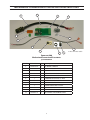
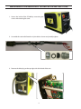
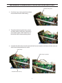
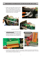
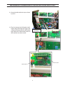
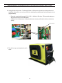
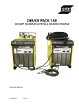
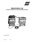
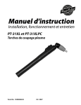
Mechanized Conversion Kit Installation Instructions
for PC-900
0558008549 03/2011
Be sure this information reaches the operator.
You can get extra copies through your supplier.
caution
These INSTRUCTIONS are for experienced operators. If you are not fully familiar with the
principles of operation and safe practices for arc welding and cutting equipment, we urge
you to read our booklet, “Precautions and Safe Practices for Arc Welding, Cutting, and
Gouging,” Form 52-529. Do NOT permit untrained persons to install, operate, or maintain
this equipment. Do NOT attempt to install or operate this equipment until you have read
and fully understand these instructions. If you do not fully understand these instructions,
contact your supplier for further information. Be sure to read the Safety Precautions before installing or operating this equipment.
USER RESPONSIBILITY
This equipment will perform in conformity with the description thereof contained in this manual and accompanying labels and/or inserts when installed, operated, maintained and repaired in accordance with the instructions provided. This equipment must be checked periodically. Malfunctioning or poorly maintained equipment
should not be used. Parts that are broken, missing, worn, distorted or contaminated should be replaced immediately. Should such repair or replacement become necessary, the manufacturer recommends that a telephone
or written request for service advice be made to the Authorized Distributor from whom it was purchased.
This equipment or any of its parts should not be altered without the prior written approval of the manufacturer.
The user of this equipment shall have the sole responsibility for any malfunction which results from improper
use, faulty maintenance, damage, improper repair or alteration by anyone other than the manufacturer or a service facility designated by the manufacturer.
READ AND UNDERSTAND THE INSTRUCTION MANUAL BEFORE INSTALLING OR OPERATING.
PROTECT YOURSELF AND OTHERS!
2
safety precautions
Users of ESAB welding and plasma cutting equipment have the ultimate responsibility for ensuring that
anyone who works on or near the equipment observes all the relevant safety precautions. Safety precautions
must meet the requirements that apply to this type of welding or plasma cutting equipment. The following
recommendations should be observed in addition to the standard regulations that apply to the workplace.
All work must be carried out by trained personnel well acquainted with the operation of the welding or plasma
cutting equipment. Incorrect operation of the equipment may lead to hazardous situations which can result in
injury to the operator and damage to the equipment.
1.
Anyone who uses welding or plasma cutting equipment must be familiar with:
- its operation
- location of emergency stops
- its function
- relevant safety precautions
- welding and / or plasma cutting
2. The operator must ensure that:
- no unauthorized person stationed within the working area of the equipment when it is started up.
- no one is unprotected when the arc is struck.
3. The workplace must:
- be suitable for the purpose
- be free from drafts
4. Personal safety equipment:
- Always wear recommended personal safety equipment, such as safety glasses, flame proof
clothing, safety gloves.
- Do not wear loose fitting items, such as scarves, bracelets, rings, etc., which could become
trapped or cause burns.
5.
General precautions:
- Make sure the return cable is connected securely.
- Work on high voltage equipment may only be carried out by a qualified electrician.
- Appropriate fire extinquishing equipment must be clearly marked and close at hand.
- Lubrication and maintenance must not be carried out on the equipment during operation.
3
safety precautions
WARNING
WELDING AND PLASMA CUTTING CAN BE INJURIOUS TO YOURSELF AND
OTHERS. TAKE PRECAUTIONS WHEN WELDING OR CUTTING. ASK FOR YOUR EMPLOYER’S SAFETY PRACTICES WHICH SHOULD BE BASED ON MANUFACTURERS’ HAZARD DATA.
ELECTRIC SHOCK - Can kill.
- Install and earth (ground) the welding or plasma cutting unit in accordance with applicable standards.
- Do not touch live electrical parts or electrodes with bare skin, wet gloves or wet clothing.
- Insulate yourself from earth and the workpiece.
- Ensure your working stance is safe.
FUMES AND GASES - Can be dangerous to health.
- Keep your head out of the fumes.
- Use ventilation, extraction at the arc, or both, to take fumes and gases away from your breathing zone
and the general area.
ARC RAYS - Can injure eyes and burn skin.
- Protect your eyes and body. Use the correct welding / plasma cutting screen and filter lens and wear
protective clothing.
- Protect bystanders with suitable screens or curtains.
FIRE HAZARD
- Sparks (spatter) can cause fire. Make sure therefore that there are no inflammable materials nearby.
NOISE - Excessive noise can damage hearing.
- Protect your ears. Use earmuffs or other hearing protection.
- Warn bystanders of the risk.
MALFUNCTION - Call for expert assistance in the event of malfunction.
READ AND UNDERSTAND THE INSTRUCTION MANUAL BEFORE INSTALLING OR OPERATING.
PROTECT YOURSELF AND OTHERS!
4
Mechanized Conversion Kit Installation Instructions
11
2
1
6, 7
4
9
5
10
2
12
3
8
2 wire connector cable
Powercut-900
Mechanized Conversion Kit contents
p/n 0558008284
Item No.
Part No.
Qty
Description
1
0558038337
1
PC BOARD - REMOTE
2
0558008457
1
RECEPTACLE / CABLE ASSY 14 PIN
3
*
1
TOROIDAL CORE
4
*
1
CONNECTOR COMBICON 10 PIN
5
*
1
CONNECTOR COMBICON 3 PIN
6
*
1
STRAIN RELIEF SEALED 1/2" ZINC
7
*
1
LOCKNUT CONDUIT 1/2"
8
*
0.75"
9
*
1
HEATSHRINK 1" BLACK
CLAMP CABLE STEEL .375 DIA
10
*
2
SCREW HEX WSH TAP #8 x .438 RIBBED
11
*
5
TYWRAP SM 4"
12
0558008111
1
KIT JUMPER - MECHANIZED LOGIC
5
Mechanized Conversion Kit Installation Instructions
1. Access the inside of the PC-900 by unscrewing the
screws and removing the cover.
2. Assemble the strain relief onto the 14 pin cable as shown and partially tighten.
3. Remove the hole plug on the top right side of the back of the unit.
6
Mechanized Conversion Kit Installation Instructions
Cut the tie wrap here
4. Cut the tie wrap, unplug control transformer
wires to allow for easier cable routing.
5. Thread the cable through the hole as shown
and allow cable to hang loose. Add locknut
and partially tighten. Add heatshrink to cable and leave loose, before applying clamp.
6. Assemble the cable clamp onto the exposed shield area and attach to the frame with the screw provided. Orient clamp downward as shown.
Cable clamp
Cable clamp in postion
Heatshrink (leave loose)
7
Mechanized Conversion Kit Installation Instructions
7. Tighten the strain relief nut from the inside
first and then tighten the outside strain relief nut. Position heatshrink over threads to
prevent power leads from contacting sharp
edges. Electrical or other suitable tape may be
used if heatshrink gun is not available.
Heatshrink or suitable tape
8. Add toroidal core to cable and leave loose, before
installing connector. Align the 10-pin connector with the pc board header to identify which
end of the connector is pin 1 and therefore ensure proper connections of the 10 cables wires.
each wire is numbered
1
2
3
4
5
6
7
8
9
10
9. Install each wire and tighten. Cable wires are numbered 1 through 10 and must be connected in numerical sequence starting with number 1. The pc board has been stamped with numbers 1 and 10 to
show the direction of sequence for the wires.
8
Mechanized Conversion Kit Installation Instructions
10. Connect the pc board to the main power control board as shown below. Connect the ring terminal
from the 14 pin cable and secure the pc board to the frame with the screw provided.
Toroidal Core
Fast-on connectors
11. Connect the fast-on connectors of the
"2-wire cable" to the 14 pin cable. Position and tie wrap toroidal core.
Tie wrap
Tie wrap
12. Route the "2-wire cable" under the pc
board and tie wrap to the frame using
the provided holes in the areas shown.
Install tie wrap as shown by arrow
13. Re-install the plug and tie wrap on the
previously unplugged wire.
9
Mechanized Conversion Kit Installation Instructions
14. Route the "2-wire cable" downward behind the shelf brace.
15. Locate the 3-pin connector on the existing main power control board.
3-pin connector
16. Align the 3-pin connector with the pc board header to identify which end of the connector aligns with
the "+" and "-" on the pc board. On the connector, insert the red wire to the "+" and black wire to the "-"
from the "2-wire cable" as shown and tighten.
red wire "+"
17. Plug in the 3-pin connector on the pc board.
black wire "-"
10
Mechanized Conversion Kit Installation Instructions
18. Secure the cable with a tie wrap as shown
by arrow.
19. Plug 5-pin jumper into J13 header. Installing this plug will change the Trigger Lock
switch on the front panel for mechanized
logic. Refer to the mechanized section of
the machine instruction manual.
5-pin jumper
J13 header
J13 header
5-pin jumper
11
Mechanized Conversion Kit Installation Instructions
20. Voltage Divider Adjustment: The Voltage Divider or VDR can be adjusted to provide optimum cut
capability. More precise cuts can be tuned in by adjusting the potentiometer and making test cuts to
gauge accuracy.
•
•
Place ohm meter leads between P25-1 & P25-3. Set R81 to 750 ohms. (This nominal setting usually performed at pc board calibration).
Additional minor adjustments of the potentiometer may be performed to achieve desired cut
quality.
Potentiometer
21. Trim all tie wraps and replace the unit's
cover.
12
Mechanized Conversion Kit Installation Instructions
Mechanized Conversion Kit Schematic
PC-900
13
notes
14
Revision History
1. 03/2011 - Updated mechanized conversion kit contents per J. Magee.
15
ESAB Welding & Cutting Products, Florence, SC Welding Equipment COMMUNICATION GUIDE - CUSTOMER SERVICES
A.
CUSTOMER SERVICE QUESTIONS:
Telephone: (800)362-7080 / Fax: (800) 634-7548
Hours: 8:00 AM to 7:00 PM EST
Order Entry
Product Availability
Pricing Order Information Returns
B.
ENGINEERING SERVICE:
Telephone: (843) 664-4416 / Fax : (800) 446-5693
Hours: 7:30 AM to 5:00 PM EST
Warranty Returns Authorized Repair Stations Welding Equipment Troubleshooting
C.
TECHNICAL SERVICE:
Telephone: (800) ESAB-123/ Fax: (843) 664-4452
Part Numbers
Technical Applications
Specifications
Hours: 8:00 AM to 5:00 PM EST
Equipment Recommendations
D.
LITERATURE REQUESTS:
Telephone: (843) 664-5562 / Fax: (843) 664-5548
Hours: 7:30 AM to 4:00 PM EST
E.
WELDING EQUIPMENT REPAIRS:
Telephone: (843) 664-4487 / Fax: (843) 664-5557
Repair Estimates Repair Status
Hours: 7:30 AM to 3:30 PM EST
F.
WELDING EQUIPMENT TRAINING
Telephone: (843)664-4428 / Fax: (843) 679-5864
Training School Information and Registrations
Hours: 7:30 AM to 4:00 PM EST
G.
WELDING PROCESS ASSISTANCE:
Telephone: (800) ESAB-123 Hours: 7:30 AM to 4:00 PM EST
H.
TECHNICAL ASST. CONSUMABLES:
Telephone : (800) 933-7070
Hours: 7:30 AM to 5:00 PM EST
IF YOU DO NOT KNOW WHOM TO CALL
Telephone: (800) ESAB-123
Fax: (843) 664-4462
Hours: 7:30 AM to 5:00 PM EST
or
visit us on the web at http://www.esabna.com
The ESAB web site offers
Comprehensive Product Information
Material Safety Data Sheets
Warranty Registration
Instruction Literature Download Library
Distributor Locator
Global Company Information
Press Releases
Customer Feedback & Support