1
MOBILE DEVICES
Developers Guide
June 18, 2012
Part No. 8000217.A
ISO 9001 Certified
Quality Management System
© Copyright 2012 by Psion Inc.
2100 Meadowvale Boulevard, Mississauga, Ontario, Canada L5N 7J9
http://www.psion.com
This document and the information it contains is the property of Psion Inc. This document is not to be
used, reproduced or copied, in whole or in part, except for the sole purpose of assisting in proper use of
Psion manufactured goods and services by their rightful owners and users. Any other use of this document is prohibited.
Disclaimer
Every effort has been made to make this material complete, accurate, and up-to-date. In addition, changes
are periodically incorporated into new editions of the publication.
Psion Inc. reserves the right to make improvements and/or changes in the product(s) and/or the program(s) described in this document without notice, and shall not be responsible for any damages including, but not limited to, consequential damages, caused by reliance on the material presented.
Psion, the Psion logo, Mobile Devices SDK and the names of other products and services provided by
Psion are trademarks of Psion Inc.
Windows® and the Windows Logo are trademarks or registered trademarks of Microsoft Corporation in
the United States and/or other countries.
The Bluetooth® word mark and logos are owned by Bluetooth SIG, Inc. and any use of such marks by
Psion Inc. is under license.
All trademarks used herein are the property of their respective owners.
Return-To-Factory Warranty
Psion Inc. provides a return to factory warranty on this product for a period of twelve (12) months in accordance with the Statement of Limited Warranty and Limitation of Liability provided at:
www.psion.com/warranty
The warranty on Psion manufactured equipment does not extend to any product that has been tampered
with, altered, or repaired by any person other than an employee of an authorized Psion service organization. See Psion terms and conditions of sale for full details.
Important: Psion warranties take effect on the date of shipment.
Service and Information
Psion provides a complete range of product support services and information to its customers worldwide.
Services include technical support and product repairs. To locate your local support services, please go to:
www.psion.com/service-and-support.htm
To access further information on current and discontinued products, please go to our Teknet site and log in
or tap on “Not Registered?”, depending on whether you have previously registered for Teknet:
http://community.psion.com/support
A section of archived product information is also available online:
http://www.psion.com/products
TABLE OF
CONTENTS
Table of Contents
Chapter 1: Introduction
1.1
1.2
1.3
1.4
About This Manual . . . . . . . . . . . . . . . . . . . . . . . . . . . . . . . . . . . . . . . . . . . . . . . . . . . . . . . . . . . . . . . . . . . . . . . . . . . . . . . . . . . . . . . . . . . . . . . . . . 2
Text Conventions . . . . . . . . . . . . . . . . . . . . . . . . . . . . . . . . . . . . . . . . . . . . . . . . . . . . . . . . . . . . . . . . . . . . . . . . . . . . . . . . . . . . . . . . . . . . . . . . . . . 3
1.2.1
Command Syntax . . . . . . . . . . . . . . . . . . . . . . . . . . . . . . . . . . . . . . . . . . . . . . . . . . . . . . . . . . . . . . . . . . . . . . . . . . . . . . . . . . . . . . . . . . 3
Non-Psion Computers . . . . . . . . . . . . . . . . . . . . . . . . . . . . . . . . . . . . . . . . . . . . . . . . . . . . . . . . . . . . . . . . . . . . . . . . . . . . . . . . . . . . . . . . . . . . . . 3
Other Documentation for Application Development . . . . . . . . . . . . . . . . . . . . . . . . . . . . . . . . . . . . . . . . . . . . . . . . . . . . . . . . . . . . 4
Chapter 2: Backlight
2.1
2.2
2.3
2.4
2.5
Backlighting . . . . . . . . . . . . . . . . . . . . . . . . . . . . . . . . . . . . . . . . . . . . . . . . . . . . . . . . . . . . . . . . . . . . . . . . . . . . . . . . . . . . . . . . . . . . . . . . . . . . . . . . . 7
2.1.1
Omnii and EP10 . . . . . . . . . . . . . . . . . . . . . . . . . . . . . . . . . . . . . . . . . . . . . . . . . . . . . . . . . . . . . . . . . . . . . . . . . . . . . . . . . . . . . . . . . . . . 7
2.1.2
Thresholds. . . . . . . . . . . . . . . . . . . . . . . . . . . . . . . . . . . . . . . . . . . . . . . . . . . . . . . . . . . . . . . . . . . . . . . . . . . . . . . . . . . . . . . . . . . . . . . . . . 7
2.1.3
Timeouts. . . . . . . . . . . . . . . . . . . . . . . . . . . . . . . . . . . . . . . . . . . . . . . . . . . . . . . . . . . . . . . . . . . . . . . . . . . . . . . . . . . . . . . . . . . . . . . . . . . . 7
Backlight Configuration Parameters . . . . . . . . . . . . . . . . . . . . . . . . . . . . . . . . . . . . . . . . . . . . . . . . . . . . . . . . . . . . . . . . . . . . . . . . . . . . . . 9
2.2.1
Mobile Devices SDK Version 5.4 and Later. . . . . . . . . . . . . . . . . . . . . . . . . . . . . . . . . . . . . . . . . . . . . . . . . . . . . . . . . . . . . . 9
2.2.2 Mobile Devices SDK Version 5.3 and Earlier . . . . . . . . . . . . . . . . . . . . . . . . . . . . . . . . . . . . . . . . . . . . . . . . . . . . . . . . . . . . 10
Getting Started with Backlights . . . . . . . . . . . . . . . . . . . . . . . . . . . . . . . . . . . . . . . . . . . . . . . . . . . . . . . . . . . . . . . . . . . . . . . . . . . . . . . . . . . 13
Code Samples for Backlights. . . . . . . . . . . . . . . . . . . . . . . . . . . . . . . . . . . . . . . . . . . . . . . . . . . . . . . . . . . . . . . . . . . . . . . . . . . . . . . . . . . . . . . 13
Backlight API Elements . . . . . . . . . . . . . . . . . . . . . . . . . . . . . . . . . . . . . . . . . . . . . . . . . . . . . . . . . . . . . . . . . . . . . . . . . . . . . . . . . . . . . . . . . . . . 13
Chapter 3: Batteries and Power Management
3.1
3.2
3.3
3.4
3.5
3.6
3.7
3.8
3.9
3.10
3.11
3.12
3.13
Suspend Timeout . . . . . . . . . . . . . . . . . . . . . . . . . . . . . . . . . . . . . . . . . . . . . . . . . . . . . . . . . . . . . . . . . . . . . . . . . . . . . . . . . . . . . . . . . . . . . . . . . . . 17
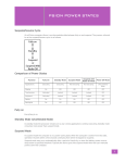
Psion Power States . . . . . . . . . . . . . . . . . . . . . . . . . . . . . . . . . . . . . . . . . . . . . . . . . . . . . . . . . . . . . . . . . . . . . . . . . . . . . . . . . . . . . . . . . . . . . . . . . 18
3.2.1
Suspend/resume Cycle . . . . . . . . . . . . . . . . . . . . . . . . . . . . . . . . . . . . . . . . . . . . . . . . . . . . . . . . . . . . . . . . . . . . . . . . . . . . . . . . . . . . 18
3.2.2 Comparison of Power States . . . . . . . . . . . . . . . . . . . . . . . . . . . . . . . . . . . . . . . . . . . . . . . . . . . . . . . . . . . . . . . . . . . . . . . . . . . . . 18
3.2.3 Fully on . . . . . . . . . . . . . . . . . . . . . . . . . . . . . . . . . . . . . . . . . . . . . . . . . . . . . . . . . . . . . . . . . . . . . . . . . . . . . . . . . . . . . . . . . . . . . . . . . . . . . 18
3.2.4 Standby Mode (Unattended Mode) . . . . . . . . . . . . . . . . . . . . . . . . . . . . . . . . . . . . . . . . . . . . . . . . . . . . . . . . . . . . . . . . . . . . . . 18
3.2.5 Suspend Mode . . . . . . . . . . . . . . . . . . . . . . . . . . . . . . . . . . . . . . . . . . . . . . . . . . . . . . . . . . . . . . . . . . . . . . . . . . . . . . . . . . . . . . . . . . . . . 18
3.2.6 Suspend with Radio Off Mode (Shutdown Mode) . . . . . . . . . . . . . . . . . . . . . . . . . . . . . . . . . . . . . . . . . . . . . . . . . . . . . . . 19
3.2.7
Power Off. . . . . . . . . . . . . . . . . . . . . . . . . . . . . . . . . . . . . . . . . . . . . . . . . . . . . . . . . . . . . . . . . . . . . . . . . . . . . . . . . . . . . . . . . . . . . . . . . . . 19
Manual Initiation of Standby and Suspend . . . . . . . . . . . . . . . . . . . . . . . . . . . . . . . . . . . . . . . . . . . . . . . . . . . . . . . . . . . . . . . . . . . . . . . 19
Wake up from Suspend Mode, or Suspend With Radio Off Mode . . . . . . . . . . . . . . . . . . . . . . . . . . . . . . . . . . . . . . . . . . . . . . 21
EP10 Power Options Registry Settings . . . . . . . . . . . . . . . . . . . . . . . . . . . . . . . . . . . . . . . . . . . . . . . . . . . . . . . . . . . . . . . . . . . . . . . . . . . 21
Programmatic Control of the Suspend/resume Cycle . . . . . . . . . . . . . . . . . . . . . . . . . . . . . . . . . . . . . . . . . . . . . . . . . . . . . . . . . . . 22
3.6.1
Initiation of Suspend . . . . . . . . . . . . . . . . . . . . . . . . . . . . . . . . . . . . . . . . . . . . . . . . . . . . . . . . . . . . . . . . . . . . . . . . . . . . . . . . . . . . . . 22
3.6.2 Selection of Wakeup Sources . . . . . . . . . . . . . . . . . . . . . . . . . . . . . . . . . . . . . . . . . . . . . . . . . . . . . . . . . . . . . . . . . . . . . . . . . . . . 22
3.6.3 Accelerometer and Gyroscope . . . . . . . . . . . . . . . . . . . . . . . . . . . . . . . . . . . . . . . . . . . . . . . . . . . . . . . . . . . . . . . . . . . . . . . . . . . 23
3.6.4 Wake up that Stops in Standby Mode . . . . . . . . . . . . . . . . . . . . . . . . . . . . . . . . . . . . . . . . . . . . . . . . . . . . . . . . . . . . . . . . . . . 23
3.6.5 Setting a Time Until Wakeup. . . . . . . . . . . . . . . . . . . . . . . . . . . . . . . . . . . . . . . . . . . . . . . . . . . . . . . . . . . . . . . . . . . . . . . . . . . . . . 23
Getting Started with the Suspend/resume Cycle . . . . . . . . . . . . . . . . . . . . . . . . . . . . . . . . . . . . . . . . . . . . . . . . . . . . . . . . . . . . . . . . 23
Code Samples for the Suspend/resume Cycle . . . . . . . . . . . . . . . . . . . . . . . . . . . . . . . . . . . . . . . . . . . . . . . . . . . . . . . . . . . . . . . . . . . 23
Suspend API Elements. . . . . . . . . . . . . . . . . . . . . . . . . . . . . . . . . . . . . . . . . . . . . . . . . . . . . . . . . . . . . . . . . . . . . . . . . . . . . . . . . . . . . . . . . . . . . . 23
Power Management . . . . . . . . . . . . . . . . . . . . . . . . . . . . . . . . . . . . . . . . . . . . . . . . . . . . . . . . . . . . . . . . . . . . . . . . . . . . . . . . . . . . . . . . . . . . . . . . 23
3.10.1 Events . . . . . . . . . . . . . . . . . . . . . . . . . . . . . . . . . . . . . . . . . . . . . . . . . . . . . . . . . . . . . . . . . . . . . . . . . . . . . . . . . . . . . . . . . . . . . . . . . . . . . . 23
Battery Information . . . . . . . . . . . . . . . . . . . . . . . . . . . . . . . . . . . . . . . . . . . . . . . . . . . . . . . . . . . . . . . . . . . . . . . . . . . . . . . . . . . . . . . . . . . . . . . . 24
3.11.1
Battery Suspend Threshold . . . . . . . . . . . . . . . . . . . . . . . . . . . . . . . . . . . . . . . . . . . . . . . . . . . . . . . . . . . . . . . . . . . . . . . . . . . . . . 24
3.11.2 Main Battery and Backup Battery Lifetimes and Remaining Charge. . . . . . . . . . . . . . . . . . . . . . . . . . . . . . . . . 25
3.11.3 Smart Batteries . . . . . . . . . . . . . . . . . . . . . . . . . . . . . . . . . . . . . . . . . . . . . . . . . . . . . . . . . . . . . . . . . . . . . . . . . . . . . . . . . . . . . . . . . . . . 25
Smart Battery Registry Settings . . . . . . . . . . . . . . . . . . . . . . . . . . . . . . . . . . . . . . . . . . . . . . . . . . . . . . . . . . . . . . . . . . . . . . . . . . . . . . . . . . 25
Getting Started with Power Management and Smart Batteries . . . . . . . . . . . . . . . . . . . . . . . . . . . . . . . . . . . . . . . . . . . . . . . . 26
Psion Mobile Devices Developers Guide
i
Table of Contents
3.14
3.15
Code Samples for Power Management and Smart Batteries. . . . . . . . . . . . . . . . . . . . . . . . . . . . . . . . . . . . . . . . . . . . . . . . . . . 26
Power Management and Battery API Elements. . . . . . . . . . . . . . . . . . . . . . . . . . . . . . . . . . . . . . . . . . . . . . . . . . . . . . . . . . . . . . . . . . 26
Chapter 4: Reset
4.1
4.2
4.3
4.4
4.5
4.6
Reset Types and Effects . . . . . . . . . . . . . . . . . . . . . . . . . . . . . . . . . . . . . . . . . . . . . . . . . . . . . . . . . . . . . . . . . . . . . . . . . . . . . . . . . . . . . . . . . . . 29
Manual Initiation of Resets . . . . . . . . . . . . . . . . . . . . . . . . . . . . . . . . . . . . . . . . . . . . . . . . . . . . . . . . . . . . . . . . . . . . . . . . . . . . . . . . . . . . . . . . 31
Programmatic Initiation of Resets . . . . . . . . . . . . . . . . . . . . . . . . . . . . . . . . . . . . . . . . . . . . . . . . . . . . . . . . . . . . . . . . . . . . . . . . . . . . . . . . 34
4.3.1
Controlling Keyboard Resets . . . . . . . . . . . . . . . . . . . . . . . . . . . . . . . . . . . . . . . . . . . . . . . . . . . . . . . . . . . . . . . . . . . . . . . . . . . . . 34
4.3.2 Detecting and Identifying Resets . . . . . . . . . . . . . . . . . . . . . . . . . . . . . . . . . . . . . . . . . . . . . . . . . . . . . . . . . . . . . . . . . . . . . . . . 35
Getting Started with Resets . . . . . . . . . . . . . . . . . . . . . . . . . . . . . . . . . . . . . . . . . . . . . . . . . . . . . . . . . . . . . . . . . . . . . . . . . . . . . . . . . . . . . . . 35
Code Samples for Resets. . . . . . . . . . . . . . . . . . . . . . . . . . . . . . . . . . . . . . . . . . . . . . . . . . . . . . . . . . . . . . . . . . . . . . . . . . . . . . . . . . . . . . . . . . . 35
Reset API Elements . . . . . . . . . . . . . . . . . . . . . . . . . . . . . . . . . . . . . . . . . . . . . . . . . . . . . . . . . . . . . . . . . . . . . . . . . . . . . . . . . . . . . . . . . . . . . . . . . 35
Chapter 5: Display
5.1
5.2
5.3
5.4
Display . . . . . . . . . . . . . . . . . . . . . . . . . . . . . . . . . . . . . . . . . . . . . . . . . . . . . . . . . . . . . . . . . . . . . . . . . . . . . . . . . . . . . . . . . . . . . . . . . . . . . . . . . . . . . . . 39
Getting Started with the Display . . . . . . . . . . . . . . . . . . . . . . . . . . . . . . . . . . . . . . . . . . . . . . . . . . . . . . . . . . . . . . . . . . . . . . . . . . . . . . . . . . 40
Code Samples for the Display . . . . . . . . . . . . . . . . . . . . . . . . . . . . . . . . . . . . . . . . . . . . . . . . . . . . . . . . . . . . . . . . . . . . . . . . . . . . . . . . . . . . . 40
Display API Elements . . . . . . . . . . . . . . . . . . . . . . . . . . . . . . . . . . . . . . . . . . . . . . . . . . . . . . . . . . . . . . . . . . . . . . . . . . . . . . . . . . . . . . . . . . . . . . 41
Chapter 6: Indicators
6.1
6.2
6.3
6.4
6.5
6.6
6.7
Indicators . . . . . . . . . . . . . . . . . . . . . . . . . . . . . . . . . . . . . . . . . . . . . . . . . . . . . . . . . . . . . . . . . . . . . . . . . . . . . . . . . . . . . . . . . . . . . . . . . . . . . . . . . . . . 45
Using LED Colours . . . . . . . . . . . . . . . . . . . . . . . . . . . . . . . . . . . . . . . . . . . . . . . . . . . . . . . . . . . . . . . . . . . . . . . . . . . . . . . . . . . . . . . . . . . . . . . . . . 45
Controlling Pulses . . . . . . . . . . . . . . . . . . . . . . . . . . . . . . . . . . . . . . . . . . . . . . . . . . . . . . . . . . . . . . . . . . . . . . . . . . . . . . . . . . . . . . . . . . . . . . . . . . 46
Controlling Illumination Patterns . . . . . . . . . . . . . . . . . . . . . . . . . . . . . . . . . . . . . . . . . . . . . . . . . . . . . . . . . . . . . . . . . . . . . . . . . . . . . . . . . 46
Getting Started with Indicators. . . . . . . . . . . . . . . . . . . . . . . . . . . . . . . . . . . . . . . . . . . . . . . . . . . . . . . . . . . . . . . . . . . . . . . . . . . . . . . . . . . . 46
Code Samples for Indicators. . . . . . . . . . . . . . . . . . . . . . . . . . . . . . . . . . . . . . . . . . . . . . . . . . . . . . . . . . . . . . . . . . . . . . . . . . . . . . . . . . . . . . . 46
Indicator API Elements . . . . . . . . . . . . . . . . . . . . . . . . . . . . . . . . . . . . . . . . . . . . . . . . . . . . . . . . . . . . . . . . . . . . . . . . . . . . . . . . . . . . . . . . . . . . . 46
Chapter 7: Keyboard and Keyboard Remapping
7.1
7.2
7.3
Keyboard . . . . . . . . . . . . . . . . . . . . . . . . . . . . . . . . . . . . . . . . . . . . . . . . . . . . . . . . . . . . . . . . . . . . . . . . . . . . . . . . . . . . . . . . . . . . . . . . . . . . . . . . . . . . 49
7.1.1
Supported Keyboards . . . . . . . . . . . . . . . . . . . . . . . . . . . . . . . . . . . . . . . . . . . . . . . . . . . . . . . . . . . . . . . . . . . . . . . . . . . . . . . . . . . . . 49
7.1.2
Disabling The Keyboard. . . . . . . . . . . . . . . . . . . . . . . . . . . . . . . . . . . . . . . . . . . . . . . . . . . . . . . . . . . . . . . . . . . . . . . . . . . . . . . . . . . 50
7.1.3
Getting Started with Keyboards . . . . . . . . . . . . . . . . . . . . . . . . . . . . . . . . . . . . . . . . . . . . . . . . . . . . . . . . . . . . . . . . . . . . . . . . . 51
7.1.4
Code Samples for Keyboards . . . . . . . . . . . . . . . . . . . . . . . . . . . . . . . . . . . . . . . . . . . . . . . . . . . . . . . . . . . . . . . . . . . . . . . . . . . . 51
7.1.5
Keyboard API Elements. . . . . . . . . . . . . . . . . . . . . . . . . . . . . . . . . . . . . . . . . . . . . . . . . . . . . . . . . . . . . . . . . . . . . . . . . . . . . . . . . . . 51
Keyboard Remapping . . . . . . . . . . . . . . . . . . . . . . . . . . . . . . . . . . . . . . . . . . . . . . . . . . . . . . . . . . . . . . . . . . . . . . . . . . . . . . . . . . . . . . . . . . . . . . 51
7.2.1
ORANGE Key and SYM Key . . . . . . . . . . . . . . . . . . . . . . . . . . . . . . . . . . . . . . . . . . . . . . . . . . . . . . . . . . . . . . . . . . . . . . . . . . . . . . . 52
7.2.2
Keyboard Remapping Functions on Psion Computers . . . . . . . . . . . . . . . . . . . . . . . . . . . . . . . . . . . . . . . . . . . . . . . . . 53
7.2.3
Unicode Values for Psion Proprietary Keys . . . . . . . . . . . . . . . . . . . . . . . . . . . . . . . . . . . . . . . . . . . . . . . . . . . . . . . . . . . . . 55
7.2.4
Windows Mobile, and Windows CE, Virtual Keys . . . . . . . . . . . . . . . . . . . . . . . . . . . . . . . . . . . . . . . . . . . . . . . . . . . . . . . . 59
7.2.5 Windows Mobile Virtual Keys on Psion Computers . . . . . . . . . . . . . . . . . . . . . . . . . . . . . . . . . . . . . . . . . . . . . . . . . . . . 59
7.2.6 Getting Started with Key Remapping . . . . . . . . . . . . . . . . . . . . . . . . . . . . . . . . . . . . . . . . . . . . . . . . . . . . . . . . . . . . . . . . . . . 59
7.2.7 Code Samples for Key Remapping . . . . . . . . . . . . . . . . . . . . . . . . . . . . . . . . . . . . . . . . . . . . . . . . . . . . . . . . . . . . . . . . . . . . . . 59
7.2.8
Keyboard Remapping API Elements . . . . . . . . . . . . . . . . . . . . . . . . . . . . . . . . . . . . . . . . . . . . . . . . . . . . . . . . . . . . . . . . . . . . . 59
Key Insertion . . . . . . . . . . . . . . . . . . . . . . . . . . . . . . . . . . . . . . . . . . . . . . . . . . . . . . . . . . . . . . . . . . . . . . . . . . . . . . . . . . . . . . . . . . . . . . . . . . . . . . . . 59
7.3.1
Getting Started with Key Insertion . . . . . . . . . . . . . . . . . . . . . . . . . . . . . . . . . . . . . . . . . . . . . . . . . . . . . . . . . . . . . . . . . . . . . . 60
7.3.2 Code Samples for Key Insertion . . . . . . . . . . . . . . . . . . . . . . . . . . . . . . . . . . . . . . . . . . . . . . . . . . . . . . . . . . . . . . . . . . . . . . . . . 60
7.3.3
Key Insertion API Elements. . . . . . . . . . . . . . . . . . . . . . . . . . . . . . . . . . . . . . . . . . . . . . . . . . . . . . . . . . . . . . . . . . . . . . . . . . . . . . . 60
Chapter 8: Peripherals
8.1
8.2
8.3
8.4
8.5
ii
Overview . . . . . . . . . . . . . . . . . . . . . . . . . . . . . . . . . . . . . . . . . . . . . . . . . . . . . . . . . . . . . . . . . . . . . . . . . . . . . . . . . . . . . . . . . . . . . . . . . . . . . . . . . . . . 63
Definition of Terms . . . . . . . . . . . . . . . . . . . . . . . . . . . . . . . . . . . . . . . . . . . . . . . . . . . . . . . . . . . . . . . . . . . . . . . . . . . . . . . . . . . . . . . . . . . . . . . . . 63
Events . . . . . . . . . . . . . . . . . . . . . . . . . . . . . . . . . . . . . . . . . . . . . . . . . . . . . . . . . . . . . . . . . . . . . . . . . . . . . . . . . . . . . . . . . . . . . . . . . . . . . . . . . . . . . . . 63
Docking Station . . . . . . . . . . . . . . . . . . . . . . . . . . . . . . . . . . . . . . . . . . . . . . . . . . . . . . . . . . . . . . . . . . . . . . . . . . . . . . . . . . . . . . . . . . . . . . . . . . . . . 63
Tether Ports . . . . . . . . . . . . . . . . . . . . . . . . . . . . . . . . . . . . . . . . . . . . . . . . . . . . . . . . . . . . . . . . . . . . . . . . . . . . . . . . . . . . . . . . . . . . . . . . . . . . . . . . . 64
Psion Mobile Devices Developers Guide
Table of Contents
8.6
8.7
8.8
8.9
Getting Started with Peripherals . . . . . . . . . . . . . . . . . . . . . . . . . . . . . . . . . . . . . . . . . . . . . . . . . . . . . . . . . . . . . . . . . . . . . . . . . . . . . . . . . . 64
Code Samples for Peripherals . . . . . . . . . . . . . . . . . . . . . . . . . . . . . . . . . . . . . . . . . . . . . . . . . . . . . . . . . . . . . . . . . . . . . . . . . . . . . . . . . . . . . 64
Peripheral API Elements in the Mobile Devices SDK . . . . . . . . . . . . . . . . . . . . . . . . . . . . . . . . . . . . . . . . . . . . . . . . . . . . . . . . . . . . 64
Peripheral API Elements in the Hardware Development Kits (HDK) . . . . . . . . . . . . . . . . . . . . . . . . . . . . . . . . . . . . . . . . . . . 65
Chapter 9: Card Slots
9.1
Card Slots . . . . . . . . . . . . . . . . . . . . . . . . . . . . . . . . . . . . . . . . . . . . . . . . . . . . . . . . . . . . . . . . . . . . . . . . . . . . . . . . . . . . . . . . . . . . . . . . . . . . . . . . . . . 69
9.1.1
Controlling Power to the Card Slots . . . . . . . . . . . . . . . . . . . . . . . . . . . . . . . . . . . . . . . . . . . . . . . . . . . . . . . . . . . . . . . . . . . . . 71
9.1.1.1
Controlling Power Through the GUI . . . . . . . . . . . . . . . . . . . . . . . . . . . . . . . . . . . . . . . . . . . . . . . . . . . . 71
9.1.1.2
Controlling Power Through the SDK. . . . . . . . . . . . . . . . . . . . . . . . . . . . . . . . . . . . . . . . . . . . . . . . . . . . 71
9.1.2
Getting Started with Card Slots. . . . . . . . . . . . . . . . . . . . . . . . . . . . . . . . . . . . . . . . . . . . . . . . . . . . . . . . . . . . . . . . . . . . . . . . . . 72
9.1.3
Code Samples for Card Slots. . . . . . . . . . . . . . . . . . . . . . . . . . . . . . . . . . . . . . . . . . . . . . . . . . . . . . . . . . . . . . . . . . . . . . . . . . . . . 72
9.1.4
Card Slot Control API Elements. . . . . . . . . . . . . . . . . . . . . . . . . . . . . . . . . . . . . . . . . . . . . . . . . . . . . . . . . . . . . . . . . . . . . . . . . . 72
Chapter 10: Serial Ports
10.1
10.2
10.3
10.4
10.5
10.6
10.7
10.8
10.9
10.10
10.11
10.12
Overview . . . . . . . . . . . . . . . . . . . . . . . . . . . . . . . . . . . . . . . . . . . . . . . . . . . . . . . . . . . . . . . . . . . . . . . . . . . . . . . . . . . . . . . . . . . . . . . . . . . . . . . . . . . . 75
Workabout Pro Serial Port Assignments . . . . . . . . . . . . . . . . . . . . . . . . . . . . . . . . . . . . . . . . . . . . . . . . . . . . . . . . . . . . . . . . . . . . . . . . . 75
7530, 7535, 8525, and 8530 Serial Port Assignments . . . . . . . . . . . . . . . . . . . . . . . . . . . . . . . . . . . . . . . . . . . . . . . . . . . . . . . . . 76
8515 Serial Port Assignments . . . . . . . . . . . . . . . . . . . . . . . . . . . . . . . . . . . . . . . . . . . . . . . . . . . . . . . . . . . . . . . . . . . . . . . . . . . . . . . . . . . . . 76
Ikôn Serial Port Assignments . . . . . . . . . . . . . . . . . . . . . . . . . . . . . . . . . . . . . . . . . . . . . . . . . . . . . . . . . . . . . . . . . . . . . . . . . . . . . . . . . . . . . 76
NEO Serial Port Assignments . . . . . . . . . . . . . . . . . . . . . . . . . . . . . . . . . . . . . . . . . . . . . . . . . . . . . . . . . . . . . . . . . . . . . . . . . . . . . . . . . . . . . 77
Omnii XT10 (7545XV), Omnii XT15 (7545XA), Omnii RT15 (7545XC) Serial Port Assignments . . . . . . . . . . . . . 77
EP10 (7515) Serial Port Assignments . . . . . . . . . . . . . . . . . . . . . . . . . . . . . . . . . . . . . . . . . . . . . . . . . . . . . . . . . . . . . . . . . . . . . . . . . . . . . 78
Java . . . . . . . . . . . . . . . . . . . . . . . . . . . . . . . . . . . . . . . . . . . . . . . . . . . . . . . . . . . . . . . . . . . . . . . . . . . . . . . . . . . . . . . . . . . . . . . . . . . . . . . . . . . . . . . . . . 78
Getting Started with Serial Ports. . . . . . . . . . . . . . . . . . . . . . . . . . . . . . . . . . . . . . . . . . . . . . . . . . . . . . . . . . . . . . . . . . . . . . . . . . . . . . . . . . 78
Code Samples for Serial Ports. . . . . . . . . . . . . . . . . . . . . . . . . . . . . . . . . . . . . . . . . . . . . . . . . . . . . . . . . . . . . . . . . . . . . . . . . . . . . . . . . . . . . 79
Serial Port API Elements . . . . . . . . . . . . . . . . . . . . . . . . . . . . . . . . . . . . . . . . . . . . . . . . . . . . . . . . . . . . . . . . . . . . . . . . . . . . . . . . . . . . . . . . . . 79
Chapter 11: Permanent Storage
11.1
11.2
11.3
11.4
11.5
Permanent Storage . . . . . . . . . . . . . . . . . . . . . . . . . . . . . . . . . . . . . . . . . . . . . . . . . . . . . . . . . . . . . . . . . . . . . . . . . . . . . . . . . . . . . . . . . . . . . . . . 83
Locking Permanent Storage . . . . . . . . . . . . . . . . . . . . . . . . . . . . . . . . . . . . . . . . . . . . . . . . . . . . . . . . . . . . . . . . . . . . . . . . . . . . . . . . . . . . . . . 83
Getting Started with Permanent Storage . . . . . . . . . . . . . . . . . . . . . . . . . . . . . . . . . . . . . . . . . . . . . . . . . . . . . . . . . . . . . . . . . . . . . . . . 83
Code Samples for Permanent Storage . . . . . . . . . . . . . . . . . . . . . . . . . . . . . . . . . . . . . . . . . . . . . . . . . . . . . . . . . . . . . . . . . . . . . . . . . . . 83
Permanent Storage API Elements . . . . . . . . . . . . . . . . . . . . . . . . . . . . . . . . . . . . . . . . . . . . . . . . . . . . . . . . . . . . . . . . . . . . . . . . . . . . . . . . 83
Chapter 12: RAS (Remote Access Service)
12.1
12.2
12.3
12.4
12.5
12.6
12.7
Overview . . . . . . . . . . . . . . . . . . . . . . . . . . . . . . . . . . . . . . . . . . . . . . . . . . . . . . . . . . . . . . . . . . . . . . . . . . . . . . . . . . . . . . . . . . . . . . . . . . . . . . . . . . . . 87
Support for RAS and Windows Connection Manager on Psion Computers . . . . . . . . . . . . . . . . . . . . . . . . . . . . . . . . . . . 87
RAS Architecture . . . . . . . . . . . . . . . . . . . . . . . . . . . . . . . . . . . . . . . . . . . . . . . . . . . . . . . . . . . . . . . . . . . . . . . . . . . . . . . . . . . . . . . . . . . . . . . . . . . 88
RAS on Windows Mobile (Connection Manager) . . . . . . . . . . . . . . . . . . . . . . . . . . . . . . . . . . . . . . . . . . . . . . . . . . . . . . . . . . . . . . . . . 88
Getting Started with RAS . . . . . . . . . . . . . . . . . . . . . . . . . . . . . . . . . . . . . . . . . . . . . . . . . . . . . . . . . . . . . . . . . . . . . . . . . . . . . . . . . . . . . . . . . . 88
Code Samples for RAS . . . . . . . . . . . . . . . . . . . . . . . . . . . . . . . . . . . . . . . . . . . . . . . . . . . . . . . . . . . . . . . . . . . . . . . . . . . . . . . . . . . . . . . . . . . . . 88
RAS API Elements . . . . . . . . . . . . . . . . . . . . . . . . . . . . . . . . . . . . . . . . . . . . . . . . . . . . . . . . . . . . . . . . . . . . . . . . . . . . . . . . . . . . . . . . . . . . . . . . . . 89
Chapter 13: Scanners
13.1
13.2
13.3
13.4
Types Of Scanners . . . . . . . . . . . . . . . . . . . . . . . . . . . . . . . . . . . . . . . . . . . . . . . . . . . . . . . . . . . . . . . . . . . . . . . . . . . . . . . . . . . . . . . . . . . . . . . . . . 93
External Scanners . . . . . . . . . . . . . . . . . . . . . . . . . . . . . . . . . . . . . . . . . . . . . . . . . . . . . . . . . . . . . . . . . . . . . . . . . . . . . . . . . . . . . . . . . . . . . . . . . . 93
13.2.1 Scanner connected to a USB port . . . . . . . . . . . . . . . . . . . . . . . . . . . . . . . . . . . . . . . . . . . . . . . . . . . . . . . . . . . . . . . . . . . . . . . 93
13.2.2 Scanner connected to a serial port . . . . . . . . . . . . . . . . . . . . . . . . . . . . . . . . . . . . . . . . . . . . . . . . . . . . . . . . . . . . . . . . . . . . . . 94
13.2.3 Scanner Connected To The Tether Port By A Scanner Cable . . . . . . . . . . . . . . . . . . . . . . . . . . . . . . . . . . . . . . . . . 94
13.2.4 Scanner Connected To The Tether Port By A Tether Cable . . . . . . . . . . . . . . . . . . . . . . . . . . . . . . . . . . . . . . . . . . . 94
13.2.5 Querying an External Scanner . . . . . . . . . . . . . . . . . . . . . . . . . . . . . . . . . . . . . . . . . . . . . . . . . . . . . . . . . . . . . . . . . . . . . . . . . . . 95
Internal Scanners . . . . . . . . . . . . . . . . . . . . . . . . . . . . . . . . . . . . . . . . . . . . . . . . . . . . . . . . . . . . . . . . . . . . . . . . . . . . . . . . . . . . . . . . . . . . . . . . . . . 95
Symbologies . . . . . . . . . . . . . . . . . . . . . . . . . . . . . . . . . . . . . . . . . . . . . . . . . . . . . . . . . . . . . . . . . . . . . . . . . . . . . . . . . . . . . . . . . . . . . . . . . . . . . . . . 97
Psion Mobile Devices Developers Guide
iii
Table of Contents
13.5
13.6
13.7
13.8
Configuring Scanners . . . . . . . . . . . . . . . . . . . . . . . . . . . . . . . . . . . . . . . . . . . . . . . . . . . . . . . . . . . . . . . . . . . . . . . . . . . . . . . . . . . . . . . . . . . . . . 98
13.5.1 Configuring Through the GUI. . . . . . . . . . . . . . . . . . . . . . . . . . . . . . . . . . . . . . . . . . . . . . . . . . . . . . . . . . . . . . . . . . . . . . . . . . . . . 98
13.5.2 Configuring Using an SDK Application . . . . . . . . . . . . . . . . . . . . . . . . . . . . . . . . . . . . . . . . . . . . . . . . . . . . . . . . . . . . . . . . . . 99
13.5.3 Configuring by Scanning Configuration Bar Codes. . . . . . . . . . . . . . . . . . . . . . . . . . . . . . . . . . . . . . . . . . . . . . . . . . . . . 99
Configuring Scanners Through the Mobile Devices SDK . . . . . . . . . . . . . . . . . . . . . . . . . . . . . . . . . . . . . . . . . . . . . . . . . . . . . . . 100
13.6.1 Configuring Scanner Properties . . . . . . . . . . . . . . . . . . . . . . . . . . . . . . . . . . . . . . . . . . . . . . . . . . . . . . . . . . . . . . . . . . . . . . . . . 102
13.6.2 Code 39 Settings . . . . . . . . . . . . . . . . . . . . . . . . . . . . . . . . . . . . . . . . . . . . . . . . . . . . . . . . . . . . . . . . . . . . . . . . . . . . . . . . . . . . . . . . . . 108
13.6.3 Trioptic Code Settings. . . . . . . . . . . . . . . . . . . . . . . . . . . . . . . . . . . . . . . . . . . . . . . . . . . . . . . . . . . . . . . . . . . . . . . . . . . . . . . . . . . . . 110
13.6.4 Code 128 Settings. . . . . . . . . . . . . . . . . . . . . . . . . . . . . . . . . . . . . . . . . . . . . . . . . . . . . . . . . . . . . . . . . . . . . . . . . . . . . . . . . . . . . . . . . . 111
13.6.5 EAN 13 Settings . . . . . . . . . . . . . . . . . . . . . . . . . . . . . . . . . . . . . . . . . . . . . . . . . . . . . . . . . . . . . . . . . . . . . . . . . . . . . . . . . . . . . . . . . . . . 113
13.6.6 EAN 8 Settings. . . . . . . . . . . . . . . . . . . . . . . . . . . . . . . . . . . . . . . . . . . . . . . . . . . . . . . . . . . . . . . . . . . . . . . . . . . . . . . . . . . . . . . . . . . . . 115
13.6.7 UPC A Settings. . . . . . . . . . . . . . . . . . . . . . . . . . . . . . . . . . . . . . . . . . . . . . . . . . . . . . . . . . . . . . . . . . . . . . . . . . . . . . . . . . . . . . . . . . . . . 117
13.6.8 UPC E Settings. . . . . . . . . . . . . . . . . . . . . . . . . . . . . . . . . . . . . . . . . . . . . . . . . . . . . . . . . . . . . . . . . . . . . . . . . . . . . . . . . . . . . . . . . . . . . 119
13.6.9 UPC/EAN Shared Settings. . . . . . . . . . . . . . . . . . . . . . . . . . . . . . . . . . . . . . . . . . . . . . . . . . . . . . . . . . . . . . . . . . . . . . . . . . . . . . . . 121
13.6.10 Codabar Settings . . . . . . . . . . . . . . . . . . . . . . . . . . . . . . . . . . . . . . . . . . . . . . . . . . . . . . . . . . . . . . . . . . . . . . . . . . . . . . . . . . . . . . . . . . 123
13.6.11 Code 93 Settings . . . . . . . . . . . . . . . . . . . . . . . . . . . . . . . . . . . . . . . . . . . . . . . . . . . . . . . . . . . . . . . . . . . . . . . . . . . . . . . . . . . . . . . . . . 125
13.6.12 Code 11 Settings. . . . . . . . . . . . . . . . . . . . . . . . . . . . . . . . . . . . . . . . . . . . . . . . . . . . . . . . . . . . . . . . . . . . . . . . . . . . . . . . . . . . . . . . . . . . 127
13.6.13 Interleaved 2 of 5 Settings . . . . . . . . . . . . . . . . . . . . . . . . . . . . . . . . . . . . . . . . . . . . . . . . . . . . . . . . . . . . . . . . . . . . . . . . . . . . . . . 128
13.6.14 MSI Plessey Settings . . . . . . . . . . . . . . . . . . . . . . . . . . . . . . . . . . . . . . . . . . . . . . . . . . . . . . . . . . . . . . . . . . . . . . . . . . . . . . . . . . . . . . 131
13.6.15 Matrix 2 of 5 Settings . . . . . . . . . . . . . . . . . . . . . . . . . . . . . . . . . . . . . . . . . . . . . . . . . . . . . . . . . . . . . . . . . . . . . . . . . . . . . . . . . . . . . 133
13.6.16 Discrete 2 of 5 Settings . . . . . . . . . . . . . . . . . . . . . . . . . . . . . . . . . . . . . . . . . . . . . . . . . . . . . . . . . . . . . . . . . . . . . . . . . . . . . . . . . . . 134
13.6.17 IATA 2 of 5 Settings . . . . . . . . . . . . . . . . . . . . . . . . . . . . . . . . . . . . . . . . . . . . . . . . . . . . . . . . . . . . . . . . . . . . . . . . . . . . . . . . . . . . . . . 135
13.6.18 Telepen Settings . . . . . . . . . . . . . . . . . . . . . . . . . . . . . . . . . . . . . . . . . . . . . . . . . . . . . . . . . . . . . . . . . . . . . . . . . . . . . . . . . . . . . . . . . . . 136
13.6.19 RSS Code Settings & GS1 DataBar Settings . . . . . . . . . . . . . . . . . . . . . . . . . . . . . . . . . . . . . . . . . . . . . . . . . . . . . . . . . . . . . 138
13.6.20 PosiCode Settings . . . . . . . . . . . . . . . . . . . . . . . . . . . . . . . . . . . . . . . . . . . . . . . . . . . . . . . . . . . . . . . . . . . . . . . . . . . . . . . . . . . . . . . . . 140
13.6.21 Composite Codes . . . . . . . . . . . . . . . . . . . . . . . . . . . . . . . . . . . . . . . . . . . . . . . . . . . . . . . . . . . . . . . . . . . . . . . . . . . . . . . . . . . . . . . . . . 140
13.6.22 TLC-39 Settings. . . . . . . . . . . . . . . . . . . . . . . . . . . . . . . . . . . . . . . . . . . . . . . . . . . . . . . . . . . . . . . . . . . . . . . . . . . . . . . . . . . . . . . . . . . . 142
13.6.23 PDF417 Settings . . . . . . . . . . . . . . . . . . . . . . . . . . . . . . . . . . . . . . . . . . . . . . . . . . . . . . . . . . . . . . . . . . . . . . . . . . . . . . . . . . . . . . . . . . . 143
13.6.24 Micro PDF-417 Settings. . . . . . . . . . . . . . . . . . . . . . . . . . . . . . . . . . . . . . . . . . . . . . . . . . . . . . . . . . . . . . . . . . . . . . . . . . . . . . . . . . . . 144
13.6.25 Code 16K Settings . . . . . . . . . . . . . . . . . . . . . . . . . . . . . . . . . . . . . . . . . . . . . . . . . . . . . . . . . . . . . . . . . . . . . . . . . . . . . . . . . . . . . . . . . 145
13.6.26 Code 49 Settings . . . . . . . . . . . . . . . . . . . . . . . . . . . . . . . . . . . . . . . . . . . . . . . . . . . . . . . . . . . . . . . . . . . . . . . . . . . . . . . . . . . . . . . . . . 146
13.6.27 Codablock Settings . . . . . . . . . . . . . . . . . . . . . . . . . . . . . . . . . . . . . . . . . . . . . . . . . . . . . . . . . . . . . . . . . . . . . . . . . . . . . . . . . . . . . . . . 146
13.6.28 2D Data Matrix Settings. . . . . . . . . . . . . . . . . . . . . . . . . . . . . . . . . . . . . . . . . . . . . . . . . . . . . . . . . . . . . . . . . . . . . . . . . . . . . . . . . . . 147
13.6.29 2D QR Code Settings . . . . . . . . . . . . . . . . . . . . . . . . . . . . . . . . . . . . . . . . . . . . . . . . . . . . . . . . . . . . . . . . . . . . . . . . . . . . . . . . . . . . . . 148
13.6.30 2D MaxiCode Settings. . . . . . . . . . . . . . . . . . . . . . . . . . . . . . . . . . . . . . . . . . . . . . . . . . . . . . . . . . . . . . . . . . . . . . . . . . . . . . . . . . . . . 149
13.6.31 2D Aztec Settings . . . . . . . . . . . . . . . . . . . . . . . . . . . . . . . . . . . . . . . . . . . . . . . . . . . . . . . . . . . . . . . . . . . . . . . . . . . . . . . . . . . . . . . . . 150
13.6.32 Postal - PlaNET Settings . . . . . . . . . . . . . . . . . . . . . . . . . . . . . . . . . . . . . . . . . . . . . . . . . . . . . . . . . . . . . . . . . . . . . . . . . . . . . . . . . . 151
13.6.33 Postal - PostNET Settings. . . . . . . . . . . . . . . . . . . . . . . . . . . . . . . . . . . . . . . . . . . . . . . . . . . . . . . . . . . . . . . . . . . . . . . . . . . . . . . . . 152
13.6.34 Postal - Australian Settings. . . . . . . . . . . . . . . . . . . . . . . . . . . . . . . . . . . . . . . . . . . . . . . . . . . . . . . . . . . . . . . . . . . . . . . . . . . . . . . 153
13.6.35 Postal - Canadian Settings. . . . . . . . . . . . . . . . . . . . . . . . . . . . . . . . . . . . . . . . . . . . . . . . . . . . . . . . . . . . . . . . . . . . . . . . . . . . . . . . 153
13.6.36 Postal - Japanese Settings . . . . . . . . . . . . . . . . . . . . . . . . . . . . . . . . . . . . . . . . . . . . . . . . . . . . . . . . . . . . . . . . . . . . . . . . . . . . . . . 154
13.6.37 Postal - Kix Settings . . . . . . . . . . . . . . . . . . . . . . . . . . . . . . . . . . . . . . . . . . . . . . . . . . . . . . . . . . . . . . . . . . . . . . . . . . . . . . . . . . . . . . . 155
13.6.38 Postal - Korean Settings . . . . . . . . . . . . . . . . . . . . . . . . . . . . . . . . . . . . . . . . . . . . . . . . . . . . . . . . . . . . . . . . . . . . . . . . . . . . . . . . . . 156
13.6.39 Postal - Royal Settings . . . . . . . . . . . . . . . . . . . . . . . . . . . . . . . . . . . . . . . . . . . . . . . . . . . . . . . . . . . . . . . . . . . . . . . . . . . . . . . . . . . . 157
13.6.40 Postal - China Settings . . . . . . . . . . . . . . . . . . . . . . . . . . . . . . . . . . . . . . . . . . . . . . . . . . . . . . . . . . . . . . . . . . . . . . . . . . . . . . . . . . . . 157
Reading Bar Codes . . . . . . . . . . . . . . . . . . . . . . . . . . . . . . . . . . . . . . . . . . . . . . . . . . . . . . . . . . . . . . . . . . . . . . . . . . . . . . . . . . . . . . . . . . . . . . . . . 159
13.7.1
Initiating a Bar Code Scan . . . . . . . . . . . . . . . . . . . . . . . . . . . . . . . . . . . . . . . . . . . . . . . . . . . . . . . . . . . . . . . . . . . . . . . . . . . . . . . . 159
13.7.2 Controlling a Bar Code Scan. . . . . . . . . . . . . . . . . . . . . . . . . . . . . . . . . . . . . . . . . . . . . . . . . . . . . . . . . . . . . . . . . . . . . . . . . . . . . . 159
Scanner Events . . . . . . . . . . . . . . . . . . . . . . . . . . . . . . . . . . . . . . . . . . . . . . . . . . . . . . . . . . . . . . . . . . . . . . . . . . . . . . . . . . . . . . . . . . . . . . . . . . . . . 160
Chapter 14: Audio
14.1
14.2
14.3
14.4
14.5
14.6
iv
Sound Hardware . . . . . . . . . . . . . . . . . . . . . . . . . . . . . . . . . . . . . . . . . . . . . . . . . . . . . . . . . . . . . . . . . . . . . . . . . . . . . . . . . . . . . . . . . . . . . . . . . . . . 163
Playing Beeps Using the Mobile Devices SDK . . . . . . . . . . . . . . . . . . . . . . . . . . . . . . . . . . . . . . . . . . . . . . . . . . . . . . . . . . . . . . . . . . . 163
Playing WAV Audio Format Files Using the Mobile Devices SDK . . . . . . . . . . . . . . . . . . . . . . . . . . . . . . . . . . . . . . . . . . . . . . . 163
Getting Started with the Beeper and WAV Files . . . . . . . . . . . . . . . . . . . . . . . . . . . . . . . . . . . . . . . . . . . . . . . . . . . . . . . . . . . . . . . . . 164
Code Samples for the Beeper and WAV Files . . . . . . . . . . . . . . . . . . . . . . . . . . . . . . . . . . . . . . . . . . . . . . . . . . . . . . . . . . . . . . . . . . . . 164
Sound API Elements . . . . . . . . . . . . . . . . . . . . . . . . . . . . . . . . . . . . . . . . . . . . . . . . . . . . . . . . . . . . . . . . . . . . . . . . . . . . . . . . . . . . . . . . . . . . . . . 164
Psion Mobile Devices Developers Guide
Table of Contents
14.7
14.8
14.9
Microphone . . . . . . . . . . . . . . . . . . . . . . . . . . . . . . . . . . . . . . . . . . . . . . . . . . . . . . . . . . . . . . . . . . . . . . . . . . . . . . . . . . . . . . . . . . . . . . . . . . . . . . . . . 165
Audio Input . . . . . . . . . . . . . . . . . . . . . . . . . . . . . . . . . . . . . . . . . . . . . . . . . . . . . . . . . . . . . . . . . . . . . . . . . . . . . . . . . . . . . . . . . . . . . . . . . . . . . . . . . . 165
14.8.1 Muting the Microphone During Voice Telephone Calls. . . . . . . . . . . . . . . . . . . . . . . . . . . . . . . . . . . . . . . . . . . . . . . . . 165
14.8.2 Controlling Microphone Gain . . . . . . . . . . . . . . . . . . . . . . . . . . . . . . . . . . . . . . . . . . . . . . . . . . . . . . . . . . . . . . . . . . . . . . . . . . . . . 165
Audio Input API Elements . . . . . . . . . . . . . . . . . . . . . . . . . . . . . . . . . . . . . . . . . . . . . . . . . . . . . . . . . . . . . . . . . . . . . . . . . . . . . . . . . . . . . . . . . 166
Chapter 15: System Information
15.1
15.2
15.3
15.4
15.5
15.6
15.7
15.8
15.9
15.10
System Information . . . . . . . . . . . . . . . . . . . . . . . . . . . . . . . . . . . . . . . . . . . . . . . . . . . . . . . . . . . . . . . . . . . . . . . . . . . . . . . . . . . . . . . . . . . . . . . . 169
Machine Type . . . . . . . . . . . . . . . . . . . . . . . . . . . . . . . . . . . . . . . . . . . . . . . . . . . . . . . . . . . . . . . . . . . . . . . . . . . . . . . . . . . . . . . . . . . . . . . . . . . . . . . 169
Model . . . . . . . . . . . . . . . . . . . . . . . . . . . . . . . . . . . . . . . . . . . . . . . . . . . . . . . . . . . . . . . . . . . . . . . . . . . . . . . . . . . . . . . . . . . . . . . . . . . . . . . . . . . . . . . . 169
Unique Machine Identifier . . . . . . . . . . . . . . . . . . . . . . . . . . . . . . . . . . . . . . . . . . . . . . . . . . . . . . . . . . . . . . . . . . . . . . . . . . . . . . . . . . . . . . . . . 169
Psion Build Codes . . . . . . . . . . . . . . . . . . . . . . . . . . . . . . . . . . . . . . . . . . . . . . . . . . . . . . . . . . . . . . . . . . . . . . . . . . . . . . . . . . . . . . . . . . . . . . . . . . 169
Psion Version Numbers . . . . . . . . . . . . . . . . . . . . . . . . . . . . . . . . . . . . . . . . . . . . . . . . . . . . . . . . . . . . . . . . . . . . . . . . . . . . . . . . . . . . . . . . . . . . 170
Setting the Ratio of Program Memory to Storage Memory . . . . . . . . . . . . . . . . . . . . . . . . . . . . . . . . . . . . . . . . . . . . . . . . . . . . 170
Getting Started with System Information . . . . . . . . . . . . . . . . . . . . . . . . . . . . . . . . . . . . . . . . . . . . . . . . . . . . . . . . . . . . . . . . . . . . . . . . 170
Code Samples for System Information . . . . . . . . . . . . . . . . . . . . . . . . . . . . . . . . . . . . . . . . . . . . . . . . . . . . . . . . . . . . . . . . . . . . . . . . . . . 171
System Information API Elements . . . . . . . . . . . . . . . . . . . . . . . . . . . . . . . . . . . . . . . . . . . . . . . . . . . . . . . . . . . . . . . . . . . . . . . . . . . . . . . . 171
Chapter 16: Windows Shell
16.1
16.2
16.3
16.4
16.5
Windows Shell . . . . . . . . . . . . . . . . . . . . . . . . . . . . . . . . . . . . . . . . . . . . . . . . . . . . . . . . . . . . . . . . . . . . . . . . . . . . . . . . . . . . . . . . . . . . . . . . . . . . . . 175
Setting Windows Security . . . . . . . . . . . . . . . . . . . . . . . . . . . . . . . . . . . . . . . . . . . . . . . . . . . . . . . . . . . . . . . . . . . . . . . . . . . . . . . . . . . . . . . . . 175
Enabling and Disabling the Windows Shell . . . . . . . . . . . . . . . . . . . . . . . . . . . . . . . . . . . . . . . . . . . . . . . . . . . . . . . . . . . . . . . . . . . . . . . 175
Security Level Change Event . . . . . . . . . . . . . . . . . . . . . . . . . . . . . . . . . . . . . . . . . . . . . . . . . . . . . . . . . . . . . . . . . . . . . . . . . . . . . . . . . . . . . . 175
System Security API Elements . . . . . . . . . . . . . . . . . . . . . . . . . . . . . . . . . . . . . . . . . . . . . . . . . . . . . . . . . . . . . . . . . . . . . . . . . . . . . . . . . . . . 175
Chapter 17: Trigger Control
17.1
17.2
17.3
17.4
Overview . . . . . . . . . . . . . . . . . . . . . . . . . . . . . . . . . . . . . . . . . . . . . . . . . . . . . . . . . . . . . . . . . . . . . . . . . . . . . . . . . . . . . . . . . . . . . . . . . . . . . . . . . . . . 179
Definition Of Terms . . . . . . . . . . . . . . . . . . . . . . . . . . . . . . . . . . . . . . . . . . . . . . . . . . . . . . . . . . . . . . . . . . . . . . . . . . . . . . . . . . . . . . . . . . . . . . . . . 179
Trigger Consumer Registration . . . . . . . . . . . . . . . . . . . . . . . . . . . . . . . . . . . . . . . . . . . . . . . . . . . . . . . . . . . . . . . . . . . . . . . . . . . . . . . . . . . 179
Trigger Source IDs . . . . . . . . . . . . . . . . . . . . . . . . . . . . . . . . . . . . . . . . . . . . . . . . . . . . . . . . . . . . . . . . . . . . . . . . . . . . . . . . . . . . . . . . . . . . . . . . . . 179
17.4.1
Virtual Key Codes. . . . . . . . . . . . . . . . . . . . . . . . . . . . . . . . . . . . . . . . . . . . . . . . . . . . . . . . . . . . . . . . . . . . . . . . . . . . . . . . . . . . . . . . . . 180
17.5 Trigger Associations . . . . . . . . . . . . . . . . . . . . . . . . . . . . . . . . . . . . . . . . . . . . . . . . . . . . . . . . . . . . . . . . . . . . . . . . . . . . . . . . . . . . . . . . . . . . . . . 180
17.5.1
Trigger Control Flags. . . . . . . . . . . . . . . . . . . . . . . . . . . . . . . . . . . . . . . . . . . . . . . . . . . . . . . . . . . . . . . . . . . . . . . . . . . . . . . . . . . . . . 180
17.6 Double-Clicks . . . . . . . . . . . . . . . . . . . . . . . . . . . . . . . . . . . . . . . . . . . . . . . . . . . . . . . . . . . . . . . . . . . . . . . . . . . . . . . . . . . . . . . . . . . . . . . . . . . . . . . 180
17.7 Events . . . . . . . . . . . . . . . . . . . . . . . . . . . . . . . . . . . . . . . . . . . . . . . . . . . . . . . . . . . . . . . . . . . . . . . . . . . . . . . . . . . . . . . . . . . . . . . . . . . . . . . . . . . . . . . 181
17.7.1
Simulated Events . . . . . . . . . . . . . . . . . . . . . . . . . . . . . . . . . . . . . . . . . . . . . . . . . . . . . . . . . . . . . . . . . . . . . . . . . . . . . . . . . . . . . . . . . . 181
17.7.2 Single-Click Events and Double-Click Events. . . . . . . . . . . . . . . . . . . . . . . . . . . . . . . . . . . . . . . . . . . . . . . . . . . . . . . . . . . . 181
17.8 Getting Started with Trigger Control . . . . . . . . . . . . . . . . . . . . . . . . . . . . . . . . . . . . . . . . . . . . . . . . . . . . . . . . . . . . . . . . . . . . . . . . . . . . . 182
17.9 Code Samples for Trigger Control . . . . . . . . . . . . . . . . . . . . . . . . . . . . . . . . . . . . . . . . . . . . . . . . . . . . . . . . . . . . . . . . . . . . . . . . . . . . . . . . 182
17.10 Trigger Control API Elements . . . . . . . . . . . . . . . . . . . . . . . . . . . . . . . . . . . . . . . . . . . . . . . . . . . . . . . . . . . . . . . . . . . . . . . . . . . . . . . . . . . . . 182
Chapter 18: Wireless Local-Area Networking
18.1
18.2
18.3
18.4
18.5
18.6
18.7
18.8
Wireless Local-Area Networking (WLAN) . . . . . . . . . . . . . . . . . . . . . . . . . . . . . . . . . . . . . . . . . . . . . . . . . . . . . . . . . . . . . . . . . . . . . . . . 185
Supplicants . . . . . . . . . . . . . . . . . . . . . . . . . . . . . . . . . . . . . . . . . . . . . . . . . . . . . . . . . . . . . . . . . . . . . . . . . . . . . . . . . . . . . . . . . . . . . . . . . . . . . . . . . . 185
18.2.1 Namespaces. . . . . . . . . . . . . . . . . . . . . . . . . . . . . . . . . . . . . . . . . . . . . . . . . . . . . . . . . . . . . . . . . . . . . . . . . . . . . . . . . . . . . . . . . . . . . . . . 186
Configuring WLAN Radios . . . . . . . . . . . . . . . . . . . . . . . . . . . . . . . . . . . . . . . . . . . . . . . . . . . . . . . . . . . . . . . . . . . . . . . . . . . . . . . . . . . . . . . . . 187
Authentication Modes . . . . . . . . . . . . . . . . . . . . . . . . . . . . . . . . . . . . . . . . . . . . . . . . . . . . . . . . . . . . . . . . . . . . . . . . . . . . . . . . . . . . . . . . . . . . . . 187
Extensible Authentication Protocol (EAP) . . . . . . . . . . . . . . . . . . . . . . . . . . . . . . . . . . . . . . . . . . . . . . . . . . . . . . . . . . . . . . . . . . . . . . . 188
18.5.1 Extensible Authentication Protocol (EAP) Modes . . . . . . . . . . . . . . . . . . . . . . . . . . . . . . . . . . . . . . . . . . . . . . . . . . . . . . 188
18.5.2 EAP Authentication - Certificates And Passwords . . . . . . . . . . . . . . . . . . . . . . . . . . . . . . . . . . . . . . . . . . . . . . . . . . . . . 188
Encryption for Data Transmission . . . . . . . . . . . . . . . . . . . . . . . . . . . . . . . . . . . . . . . . . . . . . . . . . . . . . . . . . . . . . . . . . . . . . . . . . . . . . . . . 189
18.6.1 Wired Equivalent Privacy (WEP) Keys . . . . . . . . . . . . . . . . . . . . . . . . . . . . . . . . . . . . . . . . . . . . . . . . . . . . . . . . . . . . . . . . . . . 189
18.6.2 Encryption Modes . . . . . . . . . . . . . . . . . . . . . . . . . . . . . . . . . . . . . . . . . . . . . . . . . . . . . . . . . . . . . . . . . . . . . . . . . . . . . . . . . . . . . . . . . 189
Using WLANEx to Obtain Network Information . . . . . . . . . . . . . . . . . . . . . . . . . . . . . . . . . . . . . . . . . . . . . . . . . . . . . . . . . . . . . . . . . 190
Summit Radio Features . . . . . . . . . . . . . . . . . . . . . . . . . . . . . . . . . . . . . . . . . . . . . . . . . . . . . . . . . . . . . . . . . . . . . . . . . . . . . . . . . . . . . . . . . . . . 190
Psion Mobile Devices Developers Guide
v
Table of Contents
18.9
18.10
18.11
18.12
18.13
18.14
Controlling Power on all Supplicants . . . . . . . . . . . . . . . . . . . . . . . . . . . . . . . . . . . . . . . . . . . . . . . . . . . . . . . . . . . . . . . . . . . . . . . . . . . . . 190
Configuring WLAN Through the User Interface . . . . . . . . . . . . . . . . . . . . . . . . . . . . . . . . . . . . . . . . . . . . . . . . . . . . . . . . . . . . . . . . . 190
Ad hoc Networks . . . . . . . . . . . . . . . . . . . . . . . . . . . . . . . . . . . . . . . . . . . . . . . . . . . . . . . . . . . . . . . . . . . . . . . . . . . . . . . . . . . . . . . . . . . . . . . . . . . 191
Getting Started . . . . . . . . . . . . . . . . . . . . . . . . . . . . . . . . . . . . . . . . . . . . . . . . . . . . . . . . . . . . . . . . . . . . . . . . . . . . . . . . . . . . . . . . . . . . . . . . . . . . . 191
Code Samples . . . . . . . . . . . . . . . . . . . . . . . . . . . . . . . . . . . . . . . . . . . . . . . . . . . . . . . . . . . . . . . . . . . . . . . . . . . . . . . . . . . . . . . . . . . . . . . . . . . . . . . 191
WLAN API Elements . . . . . . . . . . . . . . . . . . . . . . . . . . . . . . . . . . . . . . . . . . . . . . . . . . . . . . . . . . . . . . . . . . . . . . . . . . . . . . . . . . . . . . . . . . . . . . . . 192
Chapter 19: Wireless Wide-Area Networking
19.1
19.2
19.3
19.4
Wireless Wide-Area Networking (WWAN) . . . . . . . . . . . . . . . . . . . . . . . . . . . . . . . . . . . . . . . . . . . . . . . . . . . . . . . . . . . . . . . . . . . . . . . . 195
WWAN on Devices Supported by the Mobile Devices SDK . . . . . . . . . . . . . . . . . . . . . . . . . . . . . . . . . . . . . . . . . . . . . . . . . . . . . . 195
WWAN on Devices not Supported by the Mobile Devices SDK . . . . . . . . . . . . . . . . . . . . . . . . . . . . . . . . . . . . . . . . . . . . . . . . . 195
Supported WWAN Modems . . . . . . . . . . . . . . . . . . . . . . . . . . . . . . . . . . . . . . . . . . . . . . . . . . . . . . . . . . . . . . . . . . . . . . . . . . . . . . . . . . . . . . . . 196
19.4.1 Multiplexing . . . . . . . . . . . . . . . . . . . . . . . . . . . . . . . . . . . . . . . . . . . . . . . . . . . . . . . . . . . . . . . . . . . . . . . . . . . . . . . . . . . . . . . . . . . . . . . . 196
19.4.2 Virtual Serial Port . . . . . . . . . . . . . . . . . . . . . . . . . . . . . . . . . . . . . . . . . . . . . . . . . . . . . . . . . . . . . . . . . . . . . . . . . . . . . . . . . . . . . . . . . 196
19.4.2.1 Using the Virtual Serial Port . . . . . . . . . . . . . . . . . . . . . . . . . . . . . . . . . . . . . . . . . . . . . . . . . . . . . . . . . . . . . . . . . . 197
19.4.2.2 Configuration. . . . . . . . . . . . . . . . . . . . . . . . . . . . . . . . . . . . . . . . . . . . . . . . . . . . . . . . . . . . . . . . . . . . . . . . . . . . . . . . . . . 197
19.4.2.3 AT Commands. . . . . . . . . . . . . . . . . . . . . . . . . . . . . . . . . . . . . . . . . . . . . . . . . . . . . . . . . . . . . . . . . . . . . . . . . . . . . . . . . . 197
19.4.2.4 Entering AT Commands in Windows CE . . . . . . . . . . . . . . . . . . . . . . . . . . . . . . . . . . . . . . . . . . . . . . . . . . . . . 197
19.4.3 Dial-up Data Connections. . . . . . . . . . . . . . . . . . . . . . . . . . . . . . . . . . . . . . . . . . . . . . . . . . . . . . . . . . . . . . . . . . . . . . . . . . . . . . . . . 198
19.4.3.1 Dial-up Data in GSM Networks. . . . . . . . . . . . . . . . . . . . . . . . . . . . . . . . . . . . . . . . . . . . . . . . . . . . . . . . . . . . . . . . 198
19.4.3.2 Dial-up Data in UMTS Networks . . . . . . . . . . . . . . . . . . . . . . . . . . . . . . . . . . . . . . . . . . . . . . . . . . . . . . . . . . . . . . 198
19.4.3.3 Dial-up Data in CDMA Networks . . . . . . . . . . . . . . . . . . . . . . . . . . . . . . . . . . . . . . . . . . . . . . . . . . . . . . . . . . . . . . 199
19.4.3.4 Dial-up Data in iDEN Networks . . . . . . . . . . . . . . . . . . . . . . . . . . . . . . . . . . . . . . . . . . . . . . . . . . . . . . . . . . . . . . . 199
19.4.4 Packet Data . . . . . . . . . . . . . . . . . . . . . . . . . . . . . . . . . . . . . . . . . . . . . . . . . . . . . . . . . . . . . . . . . . . . . . . . . . . . . . . . . . . . . . . . . . . . . . . . 199
19.4.5 Summary Of Modem Differences . . . . . . . . . . . . . . . . . . . . . . . . . . . . . . . . . . . . . . . . . . . . . . . . . . . . . . . . . . . . . . . . . . . . . . . . 199
19.4.6 GSM Power Driver . . . . . . . . . . . . . . . . . . . . . . . . . . . . . . . . . . . . . . . . . . . . . . . . . . . . . . . . . . . . . . . . . . . . . . . . . . . . . . . . . . . . . . . . . 199
19.5 Initializing WWAN . . . . . . . . . . . . . . . . . . . . . . . . . . . . . . . . . . . . . . . . . . . . . . . . . . . . . . . . . . . . . . . . . . . . . . . . . . . . . . . . . . . . . . . . . . . . . . . . . . . 200
19.5.1 Checking the Initialization Status of the WWAN Driver . . . . . . . . . . . . . . . . . . . . . . . . . . . . . . . . . . . . . . . . . . . . . . . . 200
19.5.2 WWAN Driver Status Flags . . . . . . . . . . . . . . . . . . . . . . . . . . . . . . . . . . . . . . . . . . . . . . . . . . . . . . . . . . . . . . . . . . . . . . . . . . . . . . . 200
19.5.3 Initializing the WWAN Driver . . . . . . . . . . . . . . . . . . . . . . . . . . . . . . . . . . . . . . . . . . . . . . . . . . . . . . . . . . . . . . . . . . . . . . . . . . . . . 202
19.6 Closing WWAN . . . . . . . . . . . . . . . . . . . . . . . . . . . . . . . . . . . . . . . . . . . . . . . . . . . . . . . . . . . . . . . . . . . . . . . . . . . . . . . . . . . . . . . . . . . . . . . . . . . . . . 205
19.7 Connecting to the Internet . . . . . . . . . . . . . . . . . . . . . . . . . . . . . . . . . . . . . . . . . . . . . . . . . . . . . . . . . . . . . . . . . . . . . . . . . . . . . . . . . . . . . . . . 206
19.7.1
Windows Embedded CE 5.0, Windows Embedded CE 6.0, Windows Mobile 2003 SE,
and Windows CE .NET 4.2 . . . . . . . . . . . . . . . . . . . . . . . . . . . . . . . . . . . . . . . . . . . . . . . . . . . . . . . . . . . . . . . . . . . . . . . . . . . 206
19.7.2 Windows Mobile and Windows Embedded Hand-Held . . . . . . . . . . . . . . . . . . . . . . . . . . . . . . . . . . . . . . . . . . . . . . . . . 208
19.7.2.1
Disconnecting from Connection Manager. . . . . . . . . . . . . . . . . . . . . . . . . . . . . . . . . . . . . . . . . . . . . . . . . . . 209
19.7.3 The DbGprs.csv File. . . . . . . . . . . . . . . . . . . . . . . . . . . . . . . . . . . . . . . . . . . . . . . . . . . . . . . . . . . . . . . . . . . . . . . . . . . . . . . . . . . . . . . . 209
19.7.4 Checking Packet Data Status. . . . . . . . . . . . . . . . . . . . . . . . . . . . . . . . . . . . . . . . . . . . . . . . . . . . . . . . . . . . . . . . . . . . . . . . . . . . . 209
19.7.5 Roaming . . . . . . . . . . . . . . . . . . . . . . . . . . . . . . . . . . . . . . . . . . . . . . . . . . . . . . . . . . . . . . . . . . . . . . . . . . . . . . . . . . . . . . . . . . . . . . . . . . . . 210
19.7.6 Connecting Manually to a WWAN Network. . . . . . . . . . . . . . . . . . . . . . . . . . . . . . . . . . . . . . . . . . . . . . . . . . . . . . . . . . . . . . 210
19.7.7 Selecting an Access Point Name (APN) . . . . . . . . . . . . . . . . . . . . . . . . . . . . . . . . . . . . . . . . . . . . . . . . . . . . . . . . . . . . . . . . . 210
19.7.8 Connecting to a VPN . . . . . . . . . . . . . . . . . . . . . . . . . . . . . . . . . . . . . . . . . . . . . . . . . . . . . . . . . . . . . . . . . . . . . . . . . . . . . . . . . . . . . . 211
19.8 Access Flags . . . . . . . . . . . . . . . . . . . . . . . . . . . . . . . . . . . . . . . . . . . . . . . . . . . . . . . . . . . . . . . . . . . . . . . . . . . . . . . . . . . . . . . . . . . . . . . . . . . . . . . . 211
19.8.1 Controlling the Interaction with the GUI . . . . . . . . . . . . . . . . . . . . . . . . . . . . . . . . . . . . . . . . . . . . . . . . . . . . . . . . . . . . . . . . 212
19.9 RSSI (Received Signal Strength Indicator) . . . . . . . . . . . . . . . . . . . . . . . . . . . . . . . . . . . . . . . . . . . . . . . . . . . . . . . . . . . . . . . . . . . . . . . 212
19.10 WWAN API Elements . . . . . . . . . . . . . . . . . . . . . . . . . . . . . . . . . . . . . . . . . . . . . . . . . . . . . . . . . . . . . . . . . . . . . . . . . . . . . . . . . . . . . . . . . . . . . . . 213
19.11 Using SMS (Short Message Service) . . . . . . . . . . . . . . . . . . . . . . . . . . . . . . . . . . . . . . . . . . . . . . . . . . . . . . . . . . . . . . . . . . . . . . . . . . . . . . 214
19.11.1 SMS API Elements. . . . . . . . . . . . . . . . . . . . . . . . . . . . . . . . . . . . . . . . . . . . . . . . . . . . . . . . . . . . . . . . . . . . . . . . . . . . . . . . . . . . . . . . . 214
19.12 WWAN Supplementary Services . . . . . . . . . . . . . . . . . . . . . . . . . . . . . . . . . . . . . . . . . . . . . . . . . . . . . . . . . . . . . . . . . . . . . . . . . . . . . . . . . . 214
19.12.1 Voice Service States. . . . . . . . . . . . . . . . . . . . . . . . . . . . . . . . . . . . . . . . . . . . . . . . . . . . . . . . . . . . . . . . . . . . . . . . . . . . . . . . . . . . . . . 215
19.13 Voice Calls on a WWAN . . . . . . . . . . . . . . . . . . . . . . . . . . . . . . . . . . . . . . . . . . . . . . . . . . . . . . . . . . . . . . . . . . . . . . . . . . . . . . . . . . . . . . . . . . . . 215
19.13.1 Initializing WWAN. . . . . . . . . . . . . . . . . . . . . . . . . . . . . . . . . . . . . . . . . . . . . . . . . . . . . . . . . . . . . . . . . . . . . . . . . . . . . . . . . . . . . . . . . . 216
19.13.2 Initializing Voice Over WWAN . . . . . . . . . . . . . . . . . . . . . . . . . . . . . . . . . . . . . . . . . . . . . . . . . . . . . . . . . . . . . . . . . . . . . . . . . . . . 216
19.13.3 Closing Voice Over WWAN. . . . . . . . . . . . . . . . . . . . . . . . . . . . . . . . . . . . . . . . . . . . . . . . . . . . . . . . . . . . . . . . . . . . . . . . . . . . . . . . 218
19.13.4 Making a Phone Call. . . . . . . . . . . . . . . . . . . . . . . . . . . . . . . . . . . . . . . . . . . . . . . . . . . . . . . . . . . . . . . . . . . . . . . . . . . . . . . . . . . . . . . 218
19.13.5 Voice Call States . . . . . . . . . . . . . . . . . . . . . . . . . . . . . . . . . . . . . . . . . . . . . . . . . . . . . . . . . . . . . . . . . . . . . . . . . . . . . . . . . . . . . . . . . . . 219
19.13.6 Receiving a Phone Call. . . . . . . . . . . . . . . . . . . . . . . . . . . . . . . . . . . . . . . . . . . . . . . . . . . . . . . . . . . . . . . . . . . . . . . . . . . . . . . . . . . . 221
vi
Psion Mobile Devices Developers Guide
Table of Contents
19.13.7
19.13.8
19.13.9
19.13.10
19.13.11
19.13.12
19.13.13
19.13.14
Processing Voice Calls . . . . . . . . . . . . . . . . . . . . . . . . . . . . . . . . . . . . . . . . . . . . . . . . . . . . . . . . . . . . . . . . . . . . . . . . . . . . . . . . . . . . 222
Terminating Voice Calls . . . . . . . . . . . . . . . . . . . . . . . . . . . . . . . . . . . . . . . . . . . . . . . . . . . . . . . . . . . . . . . . . . . . . . . . . . . . . . . . . . . 223
Call Forwarding . . . . . . . . . . . . . . . . . . . . . . . . . . . . . . . . . . . . . . . . . . . . . . . . . . . . . . . . . . . . . . . . . . . . . . . . . . . . . . . . . . . . . . . . . . . . 224
Dual-Tone Multifrequency (DTMF) . . . . . . . . . . . . . . . . . . . . . . . . . . . . . . . . . . . . . . . . . . . . . . . . . . . . . . . . . . . . . . . . . . . . . . . 224
Blocking Inbound and Outbound Calls. . . . . . . . . . . . . . . . . . . . . . . . . . . . . . . . . . . . . . . . . . . . . . . . . . . . . . . . . . . . . . . . . . . 224
Blocking Caller ID on Outgoing Calls. . . . . . . . . . . . . . . . . . . . . . . . . . . . . . . . . . . . . . . . . . . . . . . . . . . . . . . . . . . . . . . . . . . . . 224
Audio for Voice Over WWAN . . . . . . . . . . . . . . . . . . . . . . . . . . . . . . . . . . . . . . . . . . . . . . . . . . . . . . . . . . . . . . . . . . . . . . . . . . . . . 225
Voice Over WWAN Events . . . . . . . . . . . . . . . . . . . . . . . . . . . . . . . . . . . . . . . . . . . . . . . . . . . . . . . . . . . . . . . . . . . . . . . . . . . . . . . . 225
19.13.14.1 Voice Call Status Changed Event . . . . . . . . . . . . . . . . . . . . . . . . . . . . . . . . . . . . . . . . . . . . . . . . . . . . . . . . . . . . 225
19.13.14.2 Voice Call Manager Incoming Call Event. . . . . . . . . . . . . . . . . . . . . . . . . . . . . . . . . . . . . . . . . . . . . . . . . . . . . 226
19.13.15 Voice Over WWAN API Elements. . . . . . . . . . . . . . . . . . . . . . . . . . . . . . . . . . . . . . . . . . . . . . . . . . . . . . . . . . . . . . . . . . . . . . . . . 226
19.14 Phone Books . . . . . . . . . . . . . . . . . . . . . . . . . . . . . . . . . . . . . . . . . . . . . . . . . . . . . . . . . . . . . . . . . . . . . . . . . . . . . . . . . . . . . . . . . . . . . . . . . . . . . . . . 226
19.14.1 Data Coding Schemes for Phone Book Entries . . . . . . . . . . . . . . . . . . . . . . . . . . . . . . . . . . . . . . . . . . . . . . . . . . . . . . . . . 227
19.14.2 Phone Book Types. . . . . . . . . . . . . . . . . . . . . . . . . . . . . . . . . . . . . . . . . . . . . . . . . . . . . . . . . . . . . . . . . . . . . . . . . . . . . . . . . . . . . . . . . 227
19.14.3 Phone Book API Elements . . . . . . . . . . . . . . . . . . . . . . . . . . . . . . . . . . . . . . . . . . . . . . . . . . . . . . . . . . . . . . . . . . . . . . . . . . . . . . . . 228
19.15 Resource Materials . . . . . . . . . . . . . . . . . . . . . . . . . . . . . . . . . . . . . . . . . . . . . . . . . . . . . . . . . . . . . . . . . . . . . . . . . . . . . . . . . . . . . . . . . . . . . . . . . 228
Chapter 20: Registry-based WWAN API
20.1 Overview . . . . . . . . . . . . . . . . . . . . . . . . . . . . . . . . . . . . . . . . . . . . . . . . . . . . . . . . . . . . . . . . . . . . . . . . . . . . . . . . . . . . . . . . . . . . . . . . . . . . . . . . . . . . 231
20.2 Phone State Registry Settings . . . . . . . . . . . . . . . . . . . . . . . . . . . . . . . . . . . . . . . . . . . . . . . . . . . . . . . . . . . . . . . . . . . . . . . . . . . . . . . . . . . . 231
20.2.1 General Status . . . . . . . . . . . . . . . . . . . . . . . . . . . . . . . . . . . . . . . . . . . . . . . . . . . . . . . . . . . . . . . . . . . . . . . . . . . . . . . . . . . . . . . . . . . . . 231
20.2.2 Phone State Bitmask in Numerical Order . . . . . . . . . . . . . . . . . . . . . . . . . . . . . . . . . . . . . . . . . . . . . . . . . . . . . . . . . . . . . . . 232
20.2.3 Network Status . . . . . . . . . . . . . . . . . . . . . . . . . . . . . . . . . . . . . . . . . . . . . . . . . . . . . . . . . . . . . . . . . . . . . . . . . . . . . . . . . . . . . . . . . . . . 233
20.2.4 Packet Data Status . . . . . . . . . . . . . . . . . . . . . . . . . . . . . . . . . . . . . . . . . . . . . . . . . . . . . . . . . . . . . . . . . . . . . . . . . . . . . . . . . . . . . . . . 233
20.2.5 Voice Call Status. . . . . . . . . . . . . . . . . . . . . . . . . . . . . . . . . . . . . . . . . . . . . . . . . . . . . . . . . . . . . . . . . . . . . . . . . . . . . . . . . . . . . . . . . . . 234
20.3 Phone State Registry Settings in Alphabetical Order . . . . . . . . . . . . . . . . . . . . . . . . . . . . . . . . . . . . . . . . . . . . . . . . . . . . . . . . . . . 235
20.4 System Properties Registry Settings . . . . . . . . . . . . . . . . . . . . . . . . . . . . . . . . . . . . . . . . . . . . . . . . . . . . . . . . . . . . . . . . . . . . . . . . . . . . . 236
20.5 Sample Source Code . . . . . . . . . . . . . . . . . . . . . . . . . . . . . . . . . . . . . . . . . . . . . . . . . . . . . . . . . . . . . . . . . . . . . . . . . . . . . . . . . . . . . . . . . . . . . . . 236
20.6 . . . . . . . . . . . . . . . . . . . . . . . . . . . . . . . . . . . . . . . . . . . . . . . . . . . . . . . . . . . . . . . . . . . . . . . . . . . . . . . . . . . . . . . . . . . . . . . . . . . . . . . . . . . . . . . . . . . . . . . 239
Chapter 21: GPS
21.1
21.2
21.3
21.4
21.5
21.6
21.7
Support for GPS on Psion Computers . . . . . . . . . . . . . . . . . . . . . . . . . . . . . . . . . . . . . . . . . . . . . . . . . . . . . . . . . . . . . . . . . . . . . . . . . . . . 243
21.1.1
Built-in GPS . . . . . . . . . . . . . . . . . . . . . . . . . . . . . . . . . . . . . . . . . . . . . . . . . . . . . . . . . . . . . . . . . . . . . . . . . . . . . . . . . . . . . . . . . . . . . . . . 243
21.1.2 End-cap GPS . . . . . . . . . . . . . . . . . . . . . . . . . . . . . . . . . . . . . . . . . . . . . . . . . . . . . . . . . . . . . . . . . . . . . . . . . . . . . . . . . . . . . . . . . . . . . . . 243
21.1.3 External GPS . . . . . . . . . . . . . . . . . . . . . . . . . . . . . . . . . . . . . . . . . . . . . . . . . . . . . . . . . . . . . . . . . . . . . . . . . . . . . . . . . . . . . . . . . . . . . . . 243
Mobile Devices SDK Support for GPS . . . . . . . . . . . . . . . . . . . . . . . . . . . . . . . . . . . . . . . . . . . . . . . . . . . . . . . . . . . . . . . . . . . . . . . . . . . . . 243
GPS Configuration . . . . . . . . . . . . . . . . . . . . . . . . . . . . . . . . . . . . . . . . . . . . . . . . . . . . . . . . . . . . . . . . . . . . . . . . . . . . . . . . . . . . . . . . . . . . . . . . . . 244
Processing GPS Data . . . . . . . . . . . . . . . . . . . . . . . . . . . . . . . . . . . . . . . . . . . . . . . . . . . . . . . . . . . . . . . . . . . . . . . . . . . . . . . . . . . . . . . . . . . . . . . 244
Getting Started with GPS . . . . . . . . . . . . . . . . . . . . . . . . . . . . . . . . . . . . . . . . . . . . . . . . . . . . . . . . . . . . . . . . . . . . . . . . . . . . . . . . . . . . . . . . . . 244
Code Samples for GPS . . . . . . . . . . . . . . . . . . . . . . . . . . . . . . . . . . . . . . . . . . . . . . . . . . . . . . . . . . . . . . . . . . . . . . . . . . . . . . . . . . . . . . . . . . . . . 244
GPS API Elements . . . . . . . . . . . . . . . . . . . . . . . . . . . . . . . . . . . . . . . . . . . . . . . . . . . . . . . . . . . . . . . . . . . . . . . . . . . . . . . . . . . . . . . . . . . . . . . . . . 244
Chapter 22: Sensors
22.1 Introduction . . . . . . . . . . . . . . . . . . . . . . . . . . . . . . . . . . . . . . . . . . . . . . . . . . . . . . . . . . . . . . . . . . . . . . . . . . . . . . . . . . . . . . . . . . . . . . . . . . . . . . . . . 247
22.2 Accelerometer . . . . . . . . . . . . . . . . . . . . . . . . . . . . . . . . . . . . . . . . . . . . . . . . . . . . . . . . . . . . . . . . . . . . . . . . . . . . . . . . . . . . . . . . . . . . . . . . . . . . . . 247
22.2.1 Getting Started with the Accelerometer . . . . . . . . . . . . . . . . . . . . . . . . . . . . . . . . . . . . . . . . . . . . . . . . . . . . . . . . . . . . . . . . 247
22.2.2 Code Samples for the Accelerometer . . . . . . . . . . . . . . . . . . . . . . . . . . . . . . . . . . . . . . . . . . . . . . . . . . . . . . . . . . . . . . . . . . . 247
22.2.3 Accelerometer API Elements. . . . . . . . . . . . . . . . . . . . . . . . . . . . . . . . . . . . . . . . . . . . . . . . . . . . . . . . . . . . . . . . . . . . . . . . . . . . . 247
22.3 Gyroscope . . . . . . . . . . . . . . . . . . . . . . . . . . . . . . . . . . . . . . . . . . . . . . . . . . . . . . . . . . . . . . . . . . . . . . . . . . . . . . . . . . . . . . . . . . . . . . . . . . . . . . . . . . . 247
22.3.1 Getting Started with the Gyroscope . . . . . . . . . . . . . . . . . . . . . . . . . . . . . . . . . . . . . . . . . . . . . . . . . . . . . . . . . . . . . . . . . . . . . 248
22.3.2 Code Samples for the Gyroscope . . . . . . . . . . . . . . . . . . . . . . . . . . . . . . . . . . . . . . . . . . . . . . . . . . . . . . . . . . . . . . . . . . . . . . . . 248
22.3.3 Gyroscope API Elements. . . . . . . . . . . . . . . . . . . . . . . . . . . . . . . . . . . . . . . . . . . . . . . . . . . . . . . . . . . . . . . . . . . . . . . . . . . . . . . . . . 248
22.4 Digital Compass (Magnetometer) . . . . . . . . . . . . . . . . . . . . . . . . . . . . . . . . . . . . . . . . . . . . . . . . . . . . . . . . . . . . . . . . . . . . . . . . . . . . . . . . . 248
22.4.1 Getting Started with the Magnetometer . . . . . . . . . . . . . . . . . . . . . . . . . . . . . . . . . . . . . . . . . . . . . . . . . . . . . . . . . . . . . . . . 248
22.4.2 Code Samples for the Magnetometer . . . . . . . . . . . . . . . . . . . . . . . . . . . . . . . . . . . . . . . . . . . . . . . . . . . . . . . . . . . . . . . . . . . 249
22.4.3 Magnetometer API Elements. . . . . . . . . . . . . . . . . . . . . . . . . . . . . . . . . . . . . . . . . . . . . . . . . . . . . . . . . . . . . . . . . . . . . . . . . . . . . 249
Psion Mobile Devices Developers Guide
vii
Table of Contents
22.5 Light Sensor . . . . . . . . . . . . . . . . . . . . . . . . . . . . . . . . . . . . . . . . . . . . . . . . . . . . . . . . . . . . . . . . . . . . . . . . . . . . . . . . . . . . . . . . . . . . . . . . . . . . . . . . 249
22.5.1 Getting Started with the Light Sensor. . . . . . . . . . . . . . . . . . . . . . . . . . . . . . . . . . . . . . . . . . . . . . . . . . . . . . . . . . . . . . . . . . . 249
22.5.2 Code Samples for the Light Sensor. . . . . . . . . . . . . . . . . . . . . . . . . . . . . . . . . . . . . . . . . . . . . . . . . . . . . . . . . . . . . . . . . . . . . . 249
22.5.3 Light Sensor API Elements . . . . . . . . . . . . . . . . . . . . . . . . . . . . . . . . . . . . . . . . . . . . . . . . . . . . . . . . . . . . . . . . . . . . . . . . . . . . . . . 249
22.6 Proximity Sensor . . . . . . . . . . . . . . . . . . . . . . . . . . . . . . . . . . . . . . . . . . . . . . . . . . . . . . . . . . . . . . . . . . . . . . . . . . . . . . . . . . . . . . . . . . . . . . . . . . . 249
22.6.1 Getting Started with the Proximity Sensor . . . . . . . . . . . . . . . . . . . . . . . . . . . . . . . . . . . . . . . . . . . . . . . . . . . . . . . . . . . . . 250
22.6.2 Code Samples for the Proximity Sensor. . . . . . . . . . . . . . . . . . . . . . . . . . . . . . . . . . . . . . . . . . . . . . . . . . . . . . . . . . . . . . . . . 250
22.6.3 Proximity Sensor API Elements . . . . . . . . . . . . . . . . . . . . . . . . . . . . . . . . . . . . . . . . . . . . . . . . . . . . . . . . . . . . . . . . . . . . . . . . . . 250
Chapter 23: Other Features
23.1
Vibration . . . . . . . . . . . . . . . . . . . . . . . . . . . . . . . . . . . . . . . . . . . . . . . . . . . . . . . . . . . . . . . . . . . . . . . . . . . . . . . . . . . . . . . . . . . . . . . . . . . . . . . . . . . . . 253
23.1.1
Getting Started . . . . . . . . . . . . . . . . . . . . . . . . . . . . . . . . . . . . . . . . . . . . . . . . . . . . . . . . . . . . . . . . . . . . . . . . . . . . . . . . . . . . . . . . . . . . 253
23.1.2 Code Samples. . . . . . . . . . . . . . . . . . . . . . . . . . . . . . . . . . . . . . . . . . . . . . . . . . . . . . . . . . . . . . . . . . . . . . . . . . . . . . . . . . . . . . . . . . . . . . 253
23.1.3 Vibration API Elements . . . . . . . . . . . . . . . . . . . . . . . . . . . . . . . . . . . . . . . . . . . . . . . . . . . . . . . . . . . . . . . . . . . . . . . . . . . . . . . . . . . 253
23.2 Disabling Modules and Components on the EP10 . . . . . . . . . . . . . . . . . . . . . . . . . . . . . . . . . . . . . . . . . . . . . . . . . . . . . . . . . . . . . . . 253
23.3 PsionVU . . . . . . . . . . . . . . . . . . . . . . . . . . . . . . . . . . . . . . . . . . . . . . . . . . . . . . . . . . . . . . . . . . . . . . . . . . . . . . . . . . . . . . . . . . . . . . . . . . . . . . . . . . . . . 254
23.3.1 Availability of PsionVU . . . . . . . . . . . . . . . . . . . . . . . . . . . . . . . . . . . . . . . . . . . . . . . . . . . . . . . . . . . . . . . . . . . . . . . . . . . . . . . . . . . . 254
23.3.2 Downloading PsionVU Settings with Total Recall. . . . . . . . . . . . . . . . . . . . . . . . . . . . . . . . . . . . . . . . . . . . . . . . . . . . . . . 254
23.3.3 Downloading only PsionVU Settings. . . . . . . . . . . . . . . . . . . . . . . . . . . . . . . . . . . . . . . . . . . . . . . . . . . . . . . . . . . . . . . . . . . . . 254
Appendices
Appendix A: Resources
A.1
Manuals and URLs . . . . . . . . . . . . . . . . . . . . . . . . . . . . . . . . . . . . . . . . . . . . . . . . . . . . . . . . . . . . . . . . . . . . . . . . . . . . . . . . . . . . . . . . . . . . . . . . . . A-1
Appendix B: Registry Keys
B.1
Workabout Pro Registry Keys. . . . . . . . . . . . . . . . . . . . . . . . . . . . . . . . . . . . . . . . . . . . . . . . . . . . . . . . . . . . . . . . . . . . . . . . . . . . . . . . . . . . . . B-1
B.1.1
Registry Settings For Controlling VGA . . . . . . . . . . . . . . . . . . . . . . . . . . . . . . . . . . . . . . . . . . . . . . . . . . . . . . . . . . . . . . . . . . B-1
B.1.2
Registry Settings For Controlling Scanner Power . . . . . . . . . . . . . . . . . . . . . . . . . . . . . . . . . . . . . . . . . . . . . . . . . . . . . B-1
B.1.3
Registry Settings For Serial Ports . . . . . . . . . . . . . . . . . . . . . . . . . . . . . . . . . . . . . . . . . . . . . . . . . . . . . . . . . . . . . . . . . . . . . . . B-1
B.1.4
Registry Settings For Psion Device Drivers . . . . . . . . . . . . . . . . . . . . . . . . . . . . . . . . . . . . . . . . . . . . . . . . . . . . . . . . . . . . . B-2
B.1.5
Registry Settings For Non-Psion Device Drivers . . . . . . . . . . . . . . . . . . . . . . . . . . . . . . . . . . . . . . . . . . . . . . . . . . . . . . . B-2
B.1.6
Loading Non-Psion Drivers . . . . . . . . . . . . . . . . . . . . . . . . . . . . . . . . . . . . . . . . . . . . . . . . . . . . . . . . . . . . . . . . . . . . . . . . . . . . . . . B-2
Index . . . . . . . . . . . . . . . . . . . . . . . . . . . . . . . . . . . . . . . . . . . . . . . . . . . . . . . . . . . . . . . . . . . . . . . . . . . . . . . . . . . . . . . . . . . I
viii
Psion Mobile Devices Developers Guide
INTRODUCTION
INTRODUCTION
1.1
1.2
1.3
1.4
About This Manual . . . . . . . . . . . . . . . . . . . .
Text Conventions . . . . . . . . . . . . . . . . . . . . .
1.2.1
Command Syntax . . . . . . . . . . . . . .
Non-Psion Computers . . . . . . . . . . . . . . . . . .
Other Documentation for Application Development
1
.
.
.
.
.
.
.
.
.
.
.
.
.
.
.
.
.
.
.
.
.
.
.
.
.
.
.
.
.
.
.
.
.
.
.
.
.
.
.
.
.
.
.
.
.
.
.
.
.
.
.
.
.
.
.
.
.
.
.
.
.
.
.
.
.
.
.
.
.
.
.
.
.
.
.
.
.
.
.
.
.
.
.
.
.
.
.
.
.
.
.
.
.
.
.
.
.
.
.
.
.
.
.
.
.
.
.
.
.
.
.
.
.
.
.
.
.
.
.
.
.
.
.
.
.
.
.
.
.
.
.
.
.
.
.
.
.
.
.
.
.
.
.
.
.
.
.
.
.
.
.
.
.
.
.
.
.
.
.
.
.
.
.
.
.
.
.
.
.
.
.
.
.
.
.
.2
.3
.3
.3
.4
Psion Mobile Devices Developers Guide
1
Introduction
About This Manual
1.1
About This Manual
This manual provides guidance on creating applications for Psion devices running Microsoft Windows® CE,
or Windows Mobile, operating systems.
Chapter 1: Introduction
provides an overview of this manual, the other documentation available with the SDK, and
text conventions used.
Chapter 2: Backlight
describes how to control the backlights on Psion computers.
Chapter 3: Batteries and Power Management
describes how to control battery and external power supplies.
Chapter 4: Reset
describes how to reset Psion computers.
Chapter 5: Display
describes the processes for obtaining display screen information.
Chapter 6: Indicators
describes how to manipulate the LEDs.
Chapter 7: Keyboard and Keyboard Remapping
describes how to disable the keyboard and how to remap scan codes.
Chapter 8: Peripherals
describes how to detect and control tether ports and docking stations.
Chapter 9: Card Slots
describes how to control the power to card slots.
Chapter 10: Serial Ports
describes how to detect serial ports and serial port change events.
Chapter 11: Permanent Storage
describes how to access and use permanent storage.
Chapter 12: RAS (Remote Access Service)
describes how to use the Remote Access Service (RAS).
Chapter 13: Scanners
describes the configuration of scanners and bar code symbologies.
Chapter 14: Audio
describes how to control the beeper and how to play WAV files.
Chapter 15: System Information
describes how to control the Windows security and how to obtain hardware and
software information.
Chapter 16: Windows Shell
describes how to set security levels and control access to the Windows shell.
Chapter 17: Trigger Control
describes how to control the trigger sources on a Psion computer.
Chapter 18: Wireless Local-Area Networking
describes how to implement WLAN.
Chapter 19: Wireless Wide-Area Networking
describes how to implement WWAN.
Chapter 20: Registry-based WWAN API
describes how to query properties of thr WWAN modem and WWAN network.
Chapter 21: GPS
describes how use the GPS.
Chapter 22: Sensors
describes how to use the built-in sensors.
Chapter 23: Other Features
describes the vibration feature and PsionVU.
Appendix A: Resources
lists other documents and web sites where you can find information related to developing
with the Mobile Devices SDK.
Psion Mobile Devices Developers Guide
2
Introduction
Text Conventions
Appendix B: Registry Keys
lists and describes certain Workabout Pro registry keys which may be useful when developing applications on Psion computers.
1.2
Text Conventions
The following conventions and syntax are followed throughout this document, with the exception of when
referencing API commands (see Section 1.2.1: “Command Syntax”):
•
Instructions to press specific keys on the keypad are indicated with the name or symbol of the key
between square brackets.
e.g. [SPACE], [TAB], [BLUE], [A], [.], etc.
Instructions to press buttons with dedicated functions are given with the name or function of the
button in bold type.
e.g. Power, Scan, etc.
Instructions to type a specific string of text are given between quotation marks.
e.g. Type “exit”, and press [ENTER].
•
•
Note: Notes highlight additional helpful information.
Important: These statements provide important instructions or additional information that is critical to the operation of the computer or other equipment.
Warning:
>
1.2.1
These statements provide important information that may prevent injury, damage to the
equipment, or loss of data.
An arrow next to field description information (usually in tables) indicates a recommended or suggested
configuration setting.
Command Syntax
When commands are described in text the following conventions are used in the manual:
•
Elements that must be typed exactly as shown in the text are in bold.
•
Elements that are placeholders are in italic.
The general form of a command is as follows:
sample {+r | -r} argument ... [option]
Where:
1.3
Element
Meaning
sample
Indicates the name of the command or utility.
{}
Surrounds a set of choices from which you must choose one.
|
Separates two mutually exclusive choices in a syntax line. Type one of these choices, not the
symbol.
argument
Specifies a variable name or other information that you must provide, such as a path and file
name.
...
Indicates that you can type multiple arguments of the same type. Type only the information, not
the ellipsis (…).
[]
Indicates one or more optional items. Type only the information within the brackets, not the
brackets themselves.
Non-Psion Computers
The Mobile Devices SDK cannot be used on computers other than those made by Psion. Attempts to load a
Psion DLL file on a non-Psion computer fail with an error message.
3
Psion Mobile Devices Developers Guide
Chapter 1: Introduction
Other Documentation for Application Development
1.4
Other Documentation for Application Development
There are three categories of manuals that should be used when programming Psion computers.
This manual, the Developers Guide, provides an overview of the Psion devices. A single Developers Guide
covers all libraries and devices. This manual is available in Portable Document Format (PDF).
API online help is provided for each language library, in a format appropriate to that language. All information specific to the language libraries, including class, method, field, and property descriptions, are
captured by the API online help.
In addition to the developer and API documentation, each Psion computer has a dedicated User Manual.
You need to obtain an actual device in order to test device-specific features such as bar code scanners. The
User Manuals provide valuable help in getting acquainted with the features of these devices.
See Appendix A: “Manuals and URLs” for more information.
4
Psion Mobile Devices Developers Guide
2
BACKLIGHT
BACKLIGHT
2.1
2.2
2.3
2.4
2.5
Backlighting . . . . . . . . . . . . . . . . . . . . . . . . . .
2.1.1
Omnii and EP10. . . . . . . . . . . . . . . . . .
2.1.2
Thresholds . . . . . . . . . . . . . . . . . . . .
2.1.3
Timeouts . . . . . . . . . . . . . . . . . . . . .
Backlight Configuration Parameters . . . . . . . . . . . .
2.2.1
Mobile Devices SDK Version 5.4 and Later. .
2.2.2 Mobile Devices SDK Version 5.3 and Earlier .
Getting Started with Backlights . . . . . . . . . . . . . .
Code Samples for Backlights . . . . . . . . . . . . . . . .
Backlight API Elements . . . . . . . . . . . . . . . . . . .
2
.
.
.
.
.
.
.
.
.
.
.
.
.
.
.
.
.
.
.
.
.
.
.
.
.
.
.
.
.
.
.
.
.
.
.
.
.
.
.
.
.
.
.
.
.
.
.
.
.
.
.
.
.
.
.
.
.
.
.
.
.
.
.
.
.
.
.
.
.
.
.
.
.
.
.
.
.
.
.
.
.
.
.
.
.
.
.
.
.
.
.
.
.
.
.
.
.
.
.
.
.
.
.
.
.
.
.
.
.
.
.
.
.
.
.
.
.
.
.
.
.
.
.
.
.
.
.
.
.
.
.
.
.
.
.
.
.
.
.
.
.
.
.
.
.
.
.
.
.
.
.
.
.
.
.
.
.
.
.
.
.
.
.
.
.
.
.
.
.
.
.
.
.
.
.
.
.
.
.
.
.
.
.
.
.
.
.
.
.
.
.
.
.
.
.
.
.
.
.
.
.
.
.
.
.
.
.
.
.
.
.
.
.
.
.
.
.
.
.
.
.
.
.
.
.
.
.
.
.
.
.
.
.
.
.
.
.
.
.
.
.
.
.
.
.
.
.
.
.
.
.
.
.
.
.
.
.
.
.
.
.
.
.
.
.
.
.
.
.
.
.
.
.
.
.
.
.
.
.
.
.
.
.
.
.
.
.
.
.
.
.
.
.
.
.
.
.
.
.
.
.
.
.
.
.
.
.
.
.
.
.
.
.
.
.
.
.
.
.
.
.
.
.
.
.
.
.
.
.
.
.7
.7
.7
.7
.9
.9
10
13
13
13
Psion Mobile Devices Developers Guide
5
Chapter 2: Backlight
Backlighting
2.1
Backlighting
The Mobile Devices SDK provides functions that control the display and keyboard backlights. The intensity
of the backlight and the conditions under which it is activated can be queried and set using the SDK.
To conserve battery power, you can configure the backlights to switch off, or dim to half intensity, after the
computer has been inactive for a selected length of time. The following diagram shows how these times
are related:
Last device activity
Full intensity
(on-time)
Time
Half intensity
(dim-time)
Off
The last device activity is one of the following:
•
A key is pressed on the keyboard.
•
The touchscreen is pressed.
•
The scanner trigger is pressed.
•
Data is received from the host.
If the computer is operating with external power, you can configure the backlights to remain on at all times.
2.1.1
Omnii and EP10
These computers have light sensors. For information see Section 22.5 Light Sensor on page 249.
2.1.2
Thresholds
On computers with ambient light sensors (7530 & 7535), there is a threshold value that specifies the light
level at which the backlights will turn on. The values for the display and keyboard backlight thresholds are
configured independently.
Threshold values are integers between 0 (zero) and 100. A value of 0 ensures that the selected backlight is
always off. A value of 100 ensures that the backlight can turn on at all lighting levels. Intermediate values
control the level of ambient light at which the backlight turns on. The lower the value, the darker it must be
before the keyboard backlight can turn on. Regardless of the threshold settings, the backlights only come
on if there is activity to trigger it, such as a keyboard, or a touch screen, event.
2.1.3
Timeouts
Using the Mobile Devices SDK, the backlight on-times and dim-times can be set to any positive integer
within the range of the parameter (typically 0 to 2147483647, measured in milliseconds). However, when
setting the values using the GUI, the choices are limited to a handful of predetermined values presented in
a drop-down list.
If a backlight timeout is set to one of the selectable values shown in the list, then the GUI applet displays
the correct value for that timeout. On the other hand if a backlight timeout is set, using the Mobile
Devices SDK, to a value that is not on the list of selectable values, then the GUI applet displays an empty
box for that timeout setting.
For all computers that have backlights, the following tables list the on-time, and dim-time, values that are
available in the GUI.
Psion Mobile Devices Developers Guide
7
Chapter 2: Backlight
Timeouts
Windows CE-based computers
On Windows CE-based computers, the Display, and Keyboard, Backlight On-time values determine how long
the display and keyboard backlights remain on. Any user interaction (key press, touch screen press, scan,
etc.) resets both timeout counters back to the beginning. If there has been no user interaction by the end of
the keyboard on-time duration, the keyboard backlight turns off. At the end of the display on-time duration,
the display backlight dims to half intensity. If there is still no user interaction by the end of the display
dim-time duration, then the display backlight turns off completely.
Time (milliseconds)
Display
Backlight
On-time
Display
Backlight
Dim-time
Keyboard
Backlight
On-time
0
No
Yes
No
5000
Yes
Yes
Yes
10000
Yes
Yes
Yes
15000
Yes
Yes
Yes
30000
Yes
Yes
Yes
60000
Yes
Yes
Yes
120000
Yes
Yes
Yes
180000
No
No
No
240000
No
No
No
300000
Yes
Yes
Yes
360000
No
No
No
420000
No
No
No
480000
No
No
No
540000
No
No
No
600000
No
No
No
2147483647 (Always On, maximum value)
Yes
No
Yes
Windows Mobile-based computers
On Windows Mobile-based Psion computers, the display, and keyboard, backlight timeouts are not
controlled independently: Both are controlled by a single timeout value. However, there are still two timeout
values which may be set; one for when the computer is running on battery power, and one for when it is
connected to a constant external power source.
8
Time (milliseconds)
Battery Power
Backlight On-time
External Power
Backlight On-time
0
No
No
5000
No
No
10000
Yes
No
15000
No
No
30000
Yes
No
60000
Yes
Yes
120000
Yes
Yes
Psion Mobile Devices Developers Guide
Chapter 2: Backlight
Backlight Configuration Parameters
Time (milliseconds)
Battery Power
Backlight On-time
External Power
Backlight On-time
180000
Yes
Yes
240000
Yes
Yes
300000
Yes
Yes
360000
No
Yes
420000
No
Yes
480000
No
Yes
540000
No
Yes
600000
No
Yes
2147483647 (Always On, maximum value)
No1
No1
1The setting
for Always On is controlled by a checkbox that enables/disables the On-time parameter. If the
checkbox is disabled, the On-time value is ignored and the backlight remains on.
2.2
Backlight Configuration Parameters
The following universal methods are available in all development languages for getting and setting backlight configuration values—see the API Reference Manuals for the name of the method in each
development environment:
•
•
•
•
2.2.1
Get a boolean setting.
Get an integer setting
Set a boolean setting.
Set an integer setting
Mobile Devices SDK Version 5.4 and Later
For all computers the following apply:
Parameter
Range Of Values
Default Value
Display threshold (% of maximum)
0 to 100
50
Display intensity
(% of maximum)
0 to 100
50
Display timeout
(% of maximum)
0 to 100
50
Display dimtime
(% of maximum)
0 to 100
50
Display always on for external power
(boolean)
True / False
True
Keyboard threshold
(% of maximum)
0 to 100
50
Keyboard intensity
(% of maximum)
0 to 100
50
Keyboard timeout (ms)
0 to 100
50
Psion Mobile Devices Developers Guide
9
Chapter 2: Backlight
Mobile Devices SDK Version 5.3 and Earlier
2.2.2
Parameter
Range Of Values
Default Value
Keyboard dimtime
(% of maximum)
0 to 100
50
Keyboard always on for external
power (boolean)
True / False
False
Mobile Devices SDK Version 5.3 and Earlier
The following table lists the ranges of values and the default values available for each Psion computer:
Parameter
Computer
Range Of Values
Default Value
Display threshold
(%)
753x
0 to 100
71
Display intensity
Display timeout
(ms)
10
8515
N/A
8525/8530
N/A
Ikôn Windows CE
N/A
Ikôn Windows Mobile
N/A
NEO
N/A
Workabout Pro Windows CE
N/A
Workabout Pro Windows Mobile 2003 SE
N/A
753x
0 to 100
80
7545
1 to 10
7
8515
0 to 100
48
8525/8530
0 to 100
100
Ikôn Windows CE
0 to 100
65
Ikôn Windows Mobile
0 to 100
65
NEO
0 to 100
47
Workabout Pro Windows CE
0 to 100
35
Workabout Pro Windows Mobile 2003 SE
0 to 100
35
753x
0 to 2147483647
30000
7545
0 to 4294967295
30000
8515
0 to 2147483647
30000
8525/8530
0 to 2147483647
30000
Ikôn Windows CE
0 to 2147483647
30000
Ikôn Windows Mobile
60000 to 600000
300001
NEO
0 to 2147483647
30000
Workabout Pro Windows CE
0 to 2147483647
30000
Psion Mobile Devices Developers Guide
Chapter 2: Backlight
Mobile Devices SDK Version 5.3 and Earlier
Parameter
Display dimtime
(ms)
Computer
Range Of Values
Default Value
Workabout Pro Windows Mobile 2003 SE
60000 to 600000
300001
753x
0 to 2147483647
30000
7545
0 to 4294967295
30000
8515
0 to 2147483647
30000
8525/8530
0 to 2147483647
30000
Ikôn Windows CE
0 to 2147483647
30000
Ikôn Windows Mobile
N/A
NEO
0 to 2147483647
30000
Workabout Pro Windows CE
0 to 2147483647
30000
Workabout Pro Windows Mobile 2003 SE
Display always on
for external power
(boolean)
Keyboard
threshold (%)
N/A
753x
True / False
True
7545
True / False
True
8515
True / False
True
8525/8530
True / False
True
Ikôn Windows CE
True / False
True
Ikôn Windows Mobile
True / False
False
NEO
True / False
True
Workabout Pro Windows CE
True / False
True
Workabout Pro Windows Mobile 2003 SE
True / False
False
753x
0 to 100
0
7545
N/A
8515
N/A
8525/8530
N/A
Ikôn Windows CE
N/A
Ikôn Windows Mobile
N/A
NEO
N/A
Workabout Pro Windows CE
N/A
Workabout Pro Windows Mobile 2003 SE
N/A
Psion Mobile Devices Developers Guide
11
Chapter 2: Backlight
Mobile Devices SDK Version 5.3 and Earlier
Parameter
Computer
Range Of Values
Default Value
Keyboard intensity
753x
0 to 100
48
7545
1 to 10
3
8515
0 to 100
47
8525/8530
0 to 100
48
Ikôn Windows CE
0 to 100
50
Ikôn Windows Mobile
0 to 100
50
NEO
0 to 100
0
Workabout Pro Windows CE
0 to 100
40
Workabout Pro Windows Mobile 2003 SE
0 to 100
40
753x
0 to 2147483647
15000
7545
0 to 4294967295
15000
8515
0 to 2147483647
15000
8525/8530
0 to 2147483647
15000
Ikôn Windows CE
0 to 2147483647
15000
Ikôn Windows Mobile
60000 to 600000
300001
NEO
0 to 2147483647
15000
Workabout Pro Windows CE
0 to 2147483647
15000
Workabout Pro Windows Mobile 2003 SE
60000 to 600000
300001
753x
0 to 4294967296
0
7545
0 to 4294967296
0
8525/8530
0 to 4294967296
0
Workabout Pro Windows CE
0 to 4294967296
15000
Workabout Pro Windows Mobile 2003 SE
N/A
N/A
753x
True / False
False
7545
True / False
False
8515
True / False
False
8525/8530
True / False
False
Ikôn Windows CE
True / False
False
Ikôn Windows Mobile
True / False
False
Keyboard timeout
(ms)
Keyboard dimtime
(ms)
Keyboard always
on for external
power (boolean)
12
Psion Mobile Devices Developers Guide
Chapter 2: Backlight
Getting Started with Backlights
Parameter
Computer
Range Of Values
Default Value
NEO
True / False
False
Workabout Pro Windows CE
True / False
False
Workabout Pro Windows Mobile 2003 SE
True / False
False
1On Windows Mobile
devices, reading the default value returns the Battery Power Backlight On-time value
of 30000. However, when setting the backlight value, it is written to the External Power Backlight On-time
value which enforces the range of 60000 - 600000 for that parameter (1 minute to 10 minutes).
2.3
Getting Started with Backlights
For articles on Ingenuity Working that will guide you in getting started with backlights see:
community.psion.com/tags/backlight/noteDG.
2.4
Code Samples for Backlights
For postings on Ingenuity Working that contain code samples that use backlights see:
community.psion.com/tags/backlight/codeDG.
2.5
Backlight API Elements
C++: The backlights on all computers are controlled using the PsionTeklogix::Backlight namespace.
Java: The backlights on all computers are controlled using the com.teklogix.backlight package.
.NET: The backlights on all computers are controlled using the PsionTeklogix.Backlight namespace.
Omnii and EP10
These computers have light sensors.
C: Light sensor hardware on all computers with a light sensor is read, using the AmbientLight group.
C: The keyboard backlight and the display backlight on all computers with a light sensor is controlled using
the Backlight group.
Psion Mobile Devices Developers Guide
13
3
BATTERIES AND POWER
MANAGEMENT
BATTERIES AND POWER MANAGEMENT
3.1
3.2
3
Suspend Timeout . . . . . . . . . . . . . . . . . . . . . . . . . . . . . . . . . . . . .
Psion Power States . . . . . . . . . . . . . . . . . . . . . . . . . . . . . . . . . . . .
3.2.3 Fully on . . . . . . . . . . . . . . . . . . . . . . . . . . . . . . . . . . . .
3.2.4 Standby Mode (Unattended Mode) . . . . . . . . . . . . . . . . . . . .
3.2.5 Suspend Mode . . . . . . . . . . . . . . . . . . . . . . . . . . . . . . . .
3.3 Manual Initiation of Standby and Suspend . . . . . . . . . . . . . . . . . . . . . .
3.4 Wake up from Suspend Mode, or Suspend With Radio Off Mode . . . . . . . . .
3.5 EP10 Power Options Registry Settings . . . . . . . . . . . . . . . . . . . . . . . .
3.6 Programmatic Control of the Suspend/resume Cycle . . . . . . . . . . . . . . . .
3.6.1
Initiation of Suspend . . . . . . . . . . . . . . . . . . . . . . . . . . . .
3.6.2 Selection of Wakeup Sources . . . . . . . . . . . . . . . . . . . . . . .
3.6.3 Accelerometer and Gyroscope . . . . . . . . . . . . . . . . . . . . . . .
3.6.4 Wake up that Stops in Standby Mode . . . . . . . . . . . . . . . . . . .
3.6.5 Setting a Time Until Wakeup . . . . . . . . . . . . . . . . . . . . . . . .
3.7 Getting Started with the Suspend/resume Cycle . . . . . . . . . . . . . . . . . .
3.8 Code Samples for the Suspend/resume Cycle . . . . . . . . . . . . . . . . . . . .
3.9 Suspend API Elements. . . . . . . . . . . . . . . . . . . . . . . . . . . . . . . . . .
3.10 Power Management . . . . . . . . . . . . . . . . . . . . . . . . . . . . . . . . . . .
3.10.1 Events . . . . . . . . . . . . . . . . . . . . . . . . . . . . . . . . . . . . .
3.11 Battery Information . . . . . . . . . . . . . . . . . . . . . . . . . . . . . . . . . . .
3.11.1
Battery Suspend Threshold . . . . . . . . . . . . . . . . . . . . . . . .
3.11.2 Main Battery and Backup Battery Lifetimes and Remaining Charge .
3.11.3 Smart Batteries . . . . . . . . . . . . . . . . . . . . . . . . . . . . . . .
3.12 Smart Battery Registry Settings . . . . . . . . . . . . . . . . . . . . . . . . . . . .
3.13 Getting Started with Power Management and Smart Batteries . . . . . . . . . .
3.14 Code Samples for Power Management and Smart Batteries. . . . . . . . . . . .
3.15 Power Management and Battery API Elements . . . . . . . . . . . . . . . . . . .
.
.
.
.
.
.
.
.
.
.
.
.
.
.
.
.
.
.
.
.
.
.
.
.
.
.
.
.
.
.
.
.
.
.
.
.
.
.
.
.
.
.
.
.
.
.
.
.
.
.
.
.
.
.
.
.
.
.
.
.
.
.
.
.
.
.
.
.
.
.
.
.
.
.
.
.
.
.
.
.
.
.
.
.
.
.
.
.
.
.
.
.
.
.
.
.
.
.
.
.
.
.
.
.
.
.
.
.
.
.
.
.
.
.
.
.
.
.
.
.
.
.
.
.
.
.
.
.
.
.
.
.
.
.
.
.
.
.
.
.
.
.
.
.
.
.
.
.
.
.
.
.
.
.
.
.
.
.
.
.
.
.
.
.
.
.
.
.
.
.
.
.
.
.
.
.
.
.
.
.
.
.
.
.
.
.
.
.
.
.
.
.
.
.
.
.
.
.
.
.
.
.
.
.
.
.
.
.
.
.
.
.
.
.
.
.
.
.
.
.
.
.
.
.
.
.
.
.
.
.
.
.
.
.
.
.
.
.
.
.
.
.
.
.
.
.
.
.
.
.
.
.
.
.
.
.
.
.
.
.
.
.
.
.
.
.
.
.
.
.
.
.
.
.
.
.
.
.
.
.
.
.
.
.
.
.
.
.
.
.
.
.
.
.
.
.
.
.
.
.
.
.
.
.
.
.
.
.
.
.
.
.
.
.
.
.
.
.
.
.
.
.
.
.
.
.
.
.
.
.
.
.
.
.
.
.
.
.
.
.
.
.
.
.
.
.
.
.
.
.
.
.
.
.
.
.
.
.
.
.
.
.
.
.
.
.
.
.
.
.
.
.
.
.
.
.
.
.
.
.
.
.
.
.
.
.
.
.
.
.
.
.
.
.
.
.
.
.
.
.
.
.
.
.
.
.
.
.
.
.
.
.
.
.
.
.
.
.
.
.
.
.
.
.
.
.
.
.
.
.
.
.
.
.
.
.
.
.
.
.
.
.
.
.
.
.
.
.
.
.
.
.
.
.
.
.
.
.
.
.
.
.
.
.
.
.
.
.
.
.
.
.
.
.
.
.
.
.
.
.
.
.
.
.
.
.
.
.
.
.
.
.
.
.
.
.
.
.
.
.
.
.
.
.
.
.
.
.
.
.
.
.
.
17
18
18
18
18
19
21
21
22
22
22
23
23
23
23
23
23
23
23
24
24
25
25
25
26
26
26
Psion Mobile Devices Developers Guide
15
Chapter 3: Batteries and Power Management
Suspend Timeout
3.1
Suspend Timeout
The suspend timeout determines how long the computer will wait after any activity (key press, scan, or
touch screen event, or a wireless radio transmission) before it goes into suspend mode.
When the computer wakes, the device returns to the normal powered state. The backlight, the display, and
all peripheral devices turn on and the suspend timer begins counting again.
The suspend timeout is configured as an integer variable measured in seconds. Any value between 0 and
the maximum value of 2147483647 can be configured, however the GUI Power applet only allows a small
number of predefined values to be set. If you set the suspend timeout using the Mobile Devices SDK to a
value not on the predefined list, the GUI Power applet displays the default value for that setting.
The following tables list of predefined GUI Power applet suspend timeouts, and their corresponding integer
values in seconds:
Windows CE-based computers
Timeout
Int Value
Battery Power
External Power
Never
0
Yes
Yes
1 min
60
Yes
Yes
2 min
120
Yes
Yes
3 min
180
Yes
No
4 min
240
Yes
No
5 min
300
Yes
Yes
10 min
600
Yes
Yes
15 min
900
No
Yes
30 min
1800
Yes
Yes
Windows Mobile-based computers
Timeout
Int Value
Battery Power
External Power
Never
0
Yes
Yes
1 min
60
Yes
Yes
2 min
120
Yes
Yes
3 min
180
Yes
No
4 min
240
Yes
No
5 min
300
Yes
Yes
10 min
600
No
Yes
15 min
900
No
Yes
30 min
1800
No
Yes
Psion Mobile Devices Developers Guide
17
Chapter 3: Batteries and Power Management
Psion Power States
3.2
Psion Power States
3.2.1
Suspend/resume Cycle
On all Psion computers there is an intermediate state between fully on and suspend. The process—referred
to as the suspend/resume cycle—is as follows:
3.2.2
Comparison of Power States
Function
Standby Mode
Suspend Mode
Executing
Executing
Not executing
Not executing
CPU powered
down
On
Off
Off
Off
Off
Touchscreen
Unlocked
Locked
Locked
Locked
Off
Keyboard
Unlocked
Locked
Locked
Locked
Off
Radios
On
On
On
Off
Off
Backlights
On
Off
Off
Off
Off
Applications
Display
3.2.3
Suspend with
Radio off Mode Power Off Mode
Fully On
Fully on
Everything is on.
3.2.4
Standby Mode (Unattended Mode)
In standby mode the processor remains on so any running applications continue executing. Standby mode
consumes more power than suspend mode.
3.2.5
Suspend Mode
In suspend mode the computer is in a power-saving state. When the computer is woken from this state,
operation resumes within a few seconds continuing from where it stopped on suspend.
Suspend mode may occur automatically after a period of inactivity, or when the battery power reserve
drops below a specified threshold. Typically the device goes into suspend mode when the user manually
powers down the computer.
In suspend mode, the display, the keyboard and the peripherals are powered down. The operating system
and any running applications are maintained in their current state, until the power source depletes.
18
Psion Mobile Devices Developers Guide
Chapter 3: Batteries and Power Management
Suspend with Radio Off Mode (Shutdown Mode)
3.2.6
Suspend with Radio Off Mode (Shutdown Mode)
In suspend with radio off mode the computer is in a power-saving state. When the computer is woken from
this state, operation resumes within a few seconds continuing from where it stopped on suspend. On
waking, all radios that were powered up, before entering suspend with radio off mode, are again
powered up.
Suspend with radio off mode does not occur automatically. The computer enters this mode immediately
when this option is selected on the Shutdown menu.
In suspend with radio off mode, the display, the keyboard , the radios, and the peripherals are powered
down. The operating system and any running applications are maintained in their current state, until the
power source depletes.
3.2.7
Power Off
Everything is powered down with the exception of Syscon (the component that detects power up).
The computer is woken from this state by pressing the Power button.
3.3
Manual Initiation of Standby and Suspend
Psion
Computer
Standby
Suspend
Suspend with Radio Off
(menu option hidden by
default)
Power Off
753x
(Windows CE
5.0)
Not accessible.
Press BLUE, then press
ENTER
or
Tap Start > Shutdown >
Suspend.
Not available.
Not available.
8515
(Windows CE
5.0)
Not accessible.
Press BLUE, then press
ENTER
or
Tap Start > Shutdown >
Suspend.
Not available.
Not available.
8525 / 8530
(Windows CE
5.0)
Not accessible.
Press BLUE, then press
ENTER
or
Tap Start > Shutdown >
Suspend.
Not available.
Not available.
Workabout Pro
(7525)
(Windows CE
.NET 4.2)
Not accessible.
Press BLUE, then press
ENTER/ON
or
Tap Start > Shutdown >
Suspend.
Not available.
Not available.
Workabout Pro
(7525)
(Windows Mobile
2003 SE)
Not accessible.
Press BLUE, then press
ENTER/ON
Not available.
Not available.
Workabout Pro
(7525)
(Windows Mobile
5.0)
Not accessible.
Press BLUE, then press
ENTER/ON
Not available.
Not available.
Press FN/BLUE, then
press ENTER
or
Press FN/BLUE, then
press and hold ENTER,
select Suspend, then
press ENTER.
or
Tap Start > Shutdown >
Suspend.
Not available.
Not available.
Workabout Pro
G2 (7527)
(Windows CE
5.0)
Press FN/BLUE, then
press and hold ENTER,
select Standby, then
press ENTER.
Note: Through the GUI,
you can set an option that
suspends the device when
FN/BLUE then ENTER is
pressed.
Psion Mobile Devices Developers Guide
19
Chapter 3: Batteries and Power Management
Manual Initiation of Standby and Suspend
Psion
Computer
Workabout Pro
G2 (7527)
(Windows Mobile
6.1 Classic and
Pro)
Standby
Press FN/BLUE, then
press and hold ENTER,
select Standby, then
press ENTER.
Note: Through the GUI,
you can set an option that
suspends the device when
FN/BLUE then ENTER is
pressed.
Workabout Pro3
(7527) (Windows CE 5.0)
Press and hold POWER,
select Standby, then
press ENTER.
Note: Through the GUI,
you can set an option that
suspends the device when
POWER is pressed.
Workabout Pro3
(7527)
(Windows Mobile
6.1 Classic and
Pro)
20
Press and hold POWER,
select Standby, then
press ENTER.
Suspend with Radio Off
(menu option hidden by
default)
Power Off
Press FN/BLUE, then
press ENTER
or
Press FN/BLUE, then
press and hold ENTER,
select Suspend, then
press ENTER.
Not available.
Not available.
Press POWER.
or
Press and hold POWER,
select Suspend, then
press ENTER
or
Tap Start > Shutdown >
Suspend.
Not available.
Not available.
Press POWER.
Not available.
Not available.
Suspend
Note: Through the GUI,
you can set an option that
suspends the device when
POWER is pressed.
Ikôn (7505)
(Windows CE
5.0)
Not accessible.
Press Power button
or
Tap Start > Shutdown >
Suspend.
Ikôn (7505)
(Windows Mobile
6)
Not accessible.
Press Power button.
NEO (PX750)
(Windows CE
5.0)
Not accessible.
NEO (PX750)
(Windows Mobile
6.1)
Press and hold POWER
or
Tap Start > Shutdown >
Shutdown.
Not available.
Press and hold POWER
Not available.
Press FN/BLUE, then
press ENTER
or
Tap Start > Shutdown >
Suspend.
Not available.
Not available.
Not accessible.
Press FN/BLUE, then
press ENTER.
Not available.
Not available.
Omnii XT10
(7545XV)
Omnii XT15
(7545XA)
Omnii RT15
(7545XC)
Windows
Embedded
CE 6.0)
Not accessible.
Press FN/BLUE, then
press Power
or
Tap Start > Shutdown >
Suspend.
Not available.
Not available.
Omnii XT15
(7545XA)
Omnii RT15
(7545XC)
(Windows
Embedded
Hand-Held 6.5)
Not accessible.
Press FN/BLUE, then
press Power
or
Tap Start > Shutdown >
Suspend.
Not available.
Not available.
EP10 (7515)
(Windows
Embedded
Hand-Held 6.5)
Not accessible.
Press Power button.
Psion Mobile Devices Developers Guide
Press and hold POWER
or
Tap Start > Shutdown >
Suspend With Radio Off.
Press and hold POWER
or
Tap Start > Shutdown >
Power Off.
Chapter 3: Batteries and Power Management
Wake up from Suspend Mode, or Suspend With Radio Off Mode
3.4
Wake up from Suspend Mode, or Suspend With Radio Off Mode
When one of the following occurs, a computer that is in suspend mode, or suspend with radio off mode,
wakes up:
•
•
•
•
•
•
The device is connected to external power.
A USB peripheral is connected.
The battery is inserted.
The battery door is closed.
The touch screen is touched.
Suspend mode only: The WWAN radio receives an incoming voice call, or it receives SMS or IP
data packets.
•
An expansion port, controlled through the HDK, is connected.
Not all of these wake-up sources are available on all Psion computers. Consult the user manual for your
computer to find out which features are on your device.
3.5
EP10 Power Options Registry Settings
The following registry settings on the EP10 control the appearance and behaviour of the Suspend dialog:
HKEY_LOCAL_MACHINE\Drivers\BuiltIn\PMDrv\PBC
Value Name
Value Type
Default
Description
DlgEnabled
REG_DWORD
1
Must be enabled to make the rest of the options available.
The following settings are possible:
Value
DlgShowDelay
REG_DWORD
DlgShowTimeout
REG_DWORD
DlgDefaultAction
REG_DWORD
Description
0
Disable
1
Enable
Length of time (in milliseconds) that Power must be held
before the Shutdown dialog is displayed (minimum
2000 ms).
0
0
Length of time (in milliseconds) that the Shutdown
dialog is displayed before the highlighted menu item is
automatically activated.
The following settings are possible:
Value
Description
0
Disable
≥5000
Duration in ms
Shutdown menu item that is highlighted when the
dialog opens.
The following settings are possible:
Value
Description
0
First item on the list
1
Second item on the list
2
Third item on the list
Psion Mobile Devices Developers Guide
21
Chapter 3: Batteries and Power Management
Programmatic Control of the Suspend/resume Cycle
Value Name
Value Type
Default
Description
DlgHideSuspend
REG_DWORD
0
Controls display of the Suspend option.
The following settings are possible:
DlgHideSuspendRadiosOff
DlgHideStandby
DlgHideShutdown
UseSuspendDialog
REG_DWORD
REG_DWORD
REG_DWORD
REG_DWORD
1
0
0
1
Value
Description
0
Display
1
Hide
Controls display of the Suspend with Radios Off option.
The following settings are possible:
Value
Description
0
Display
1
Hide
Controls display of the Standby option.
The following settings are possible:
Value
Description
0
Display
1
Hide
Controls display of the Power Off option.
The following settings are possible:
Value
Description
0
Display
1
Hide
Controls the Suspend dialog that is displayed when
Power is pressed very soon after a resume.
The following settings are possible:
Value
Description
0
Hide the suspend dialog.
1
Display the suspend dialog. This
prevents a second suspend
immediately after resuming.
Warning: The Suspend dialog ensures that the radios
have enough time to power up and power down. It is
recommended that this setting is not disabled.
3.6
Programmatic Control of the Suspend/resume Cycle
3.6.1
Initiation of Suspend
The Mobile Devices SDK includes APIs that can initiate a suspend. The device passes through standby mode
before going into suspend mode; however, the Mobile Devices SDK does not contain APIs than can specifically place a computer into standby mode.
3.6.2
Selection of Wakeup Sources
Using the Mobile Devices SDK you can select which potential wakeup sources are active on a device. This
option is not available through the GUI. The following functions are available:
•
•
22
EnableWakeupSource—selectively enable and disable a potential wake-up source.
IsWakeupSourceEnabled—query the status of a wake-up source.
Psion Mobile Devices Developers Guide
Chapter 3: Batteries and Power Management
Accelerometer and Gyroscope
The first time you enable a wakeup source programmatically, it may not bring the device into the fully on
state. The device is in standby mode. For a code sample showing how to deal with this see:
community.psion.com/downloads/developer_sdkhdk/m/sample__demo_code/34578.aspx.
Usually, after Windows is restarted, an enabled wakeup source brings the device out of suspend mode into
fully on. For details see Section 4.3 Programmatic Initiation of Resets on page 34.
3.6.3
Accelerometer and Gyroscope
The accelerometer and the gyroscope do not wake a computer from suspend mode.
3.6.4
Wake up that Stops in Standby Mode
For some wakeup sources—such as WWAN radio events—the wakeup event raises the device from suspend
mode into standby mode, and not to fully on. In this case the application must monitor the transition from
suspend mode to reset mode. It can then programmatically bring the device from standby mode to fully on.
3.6.5
Setting a Time Until Wakeup
To suspend a computer for a selected length of time, use the Microsoft APIs.
3.7
Getting Started with the Suspend/resume Cycle
For articles on Ingenuity Working that will guide you in getting started with the suspend/resume cycle see:
community.psion.com/tags/wakeup/noteDG.
3.8
Code Samples for the Suspend/resume Cycle
For postings on Ingenuity Working that contain code samples that use the suspend/resume cycle see:
community.psion.com/tags/wakeup/codeDG.
3.9
Suspend API Elements
You cannot programmatically put a Psion computer into standby mode.
C++: Suspend on all computers is controlled using the PsionTeklogix::PowerManagement namespace. For
suspending the computer and setting the time until wake-up use Microsoft Power Management APIs; for
details see
http://msdn.microsoft.com/en-us/library/ms895437(v=MSDN.10).aspx.
Java: Suspend on all computers is controlled using the com.teklogix.power package.
.NET: Suspend on all computers is controlled using the PsionTeklogix.Power namespace. Power can also
be controlled by the Windows Power Management Functions; for details see
http://msdn.microsoft.com/en-us/library/ms895437(v=MSDN.10).aspx.
Selection of wakeup sources
C++: Wakeup sources on all computers is controlled using the
PsionTeklogix::PowerManagement namespace.
Java: Wakeup sources on all computers is controlled using the com.teklogix.power package.
.NET: Wakeup sources on all computers is controlled using the PsionTeklogix.Power namespace.
3.10
Power Management
3.10.1
Events
C++
C++ applications must use the Microsoft RequestPowerNotifications and
GetSystemPowerStatusEx2 APIs.
Psion Mobile Devices Developers Guide
23
Chapter 3: Batteries and Power Management
Battery Information
Java and .NET
The following power state events are generated by the computer and can be detected by the Mobile
Devices SDK. These events are used by Java and .NET applications:
Event
States
Description
High
Fully charged
Low
Low charge
Critical
Needs to be charged immediately
Charging
Charging
NoSystemBattery
No battery detected
Unknown
None of the other states
On
On
Off
Full off
Critical
Critical off
Boot
Device is booting
Idle
Idle state
Suspend
Suspend state
Resume
Resume state
Reset
Reset state
Preferred
Preferred state
UserIdle
User idle state
Offline
Not on external power
Online
On external power
BackupPower
On backup power
Unknown
None of the other states
AC Power online
AC Power online
Battery status change
Power information change
Power transition
3.11
Battery Information
3.11.1
Battery Suspend Threshold
Some computers have only a small backup battery, or no backup battery. On these computers, once the
main battery has completely discharged, users have a very short time during which to change the battery
before all volatile data is lost. In this situation, it can be desirable to have the device give the low battery
warning prematurely, thus ensuring it gets replaced, or recharged, before data is lost.
Setting the battery suspend threshold forces the computer to suspend when that threshold is reached,
before the main battery has fully discharged. The battery suspend threshold is a percentage, between 0
(zero) and 100, of the maximum allowed battery threshold charge. The actual amount of charge, remaining
at the selected battery suspend threshold, is calculated based on the type of computer and the type
of battery.
24
Psion Mobile Devices Developers Guide
Chapter 3: Batteries and Power Management
Smart Battery Registry Settings
3.11.2
Main Battery and Backup Battery Lifetimes and Remaining Charge
The battery lifetime reported by the Mobile Devices SDK may not be accurate as various system configurations, power management settings, and the activity of various peripheral devices all affect the rate that
charge is drained from the battery.
It may not be possible to determine the remaining lifetime or the full lifetime of the backup battery while
the computer is being powered by an external source, such as an AC adaptor. As a result, these calls may
throw an exception if the computer is on external power.
The amount of charge reported as remaining in the battery may not be accurate. Also, this value can vary
due to the activity of peripheral devices such as radios.
3.11.3
Smart Batteries
Smart batteries can accurately report their status. The main use of these smart battery functions is to
determine when to replace old batteries. All the batteries available for the following Psion computers are
smart batteries:
•
7530
•
7535
•
8525
•
8530
•
Ikôn
•
Omnii
•
EP10
The smart battery APIs in the Mobile Devices SDK throw an exception stating Not Supported on devices
that do not support smart batteries.
Smart Battery Function
Description
GetBatteryCycleCount
This is important in determining the health of a battery, and determining when
the battery is at the end of its life.
A battery charge cycle occurs when the battery has been drained to 0%, and
then refilled to 100%, of its maximum capacity. Some batteries have a life span
that can be measured in cycle counts (usually from 500 – 1000, but can
be more).
3.12
GetBatterySerialNumber
Returns either a string or an integer.
GetBatteryManufactureDate
This measures how old the battery is. Together with the cycle count, this
determines whether the battery is wearing out too fast.
Smart Battery Registry Settings
HKEY_LOCAL_MACHINE\Services\BatteryStatus
Value Name
Value Type
Default
Value
Flags
REG_DWORD
0
Microsoft-required value for controlling an
auto-started service.
Set to 0: Enable service
Set to 4: Disable service.
CycleThreshUsed
REG_DWORD
300
The cycle-count threshold at which a terminal is considered
Good. Below this threshold it is considered Excellent.
CycleThreshOld
REG_DWORD
400
The cycle-count threshold at which a terminal is considered
Expired. Below this threshold it is considered Good.
Description
Psion Mobile Devices Developers Guide
25
Chapter 3: Batteries and Power Management
Getting Started with Power Management and Smart Batteries
3.13
Value Name
Value Type
Default
Value
ShowPopupOnResume
REG_DWORD
1
The Battery Quality dialog appears whenever external
power is connected or disconnected—the pop-up is limited to
once per minute. This flag allows the pop-up to appear on
resume as well. To disable this feature, set it to 0.
ShowWhenNew
REG_DWORD
4
The amount of time (in sec) that the pop-up stays visible
when the green, or Excellent, battery icon is displayed.
ShowWhenUsed
REG_DWORD
7
The amount of time (in sec) that the pop-up stays visible
when the yellow, or Good, battery icon is displayed.
ShowWhenOld
REG_DWORD
10
The amount of time (in sec) that the pop-up stays visible
when the red, or Expired, battery icon is displayed. If you
want this pop-up to remain visible until manually dismissed
set the value to 99999.
ShowWhenUnknown
REG_DWORD
0
The amount of time (in sec) that the Unknown pop-up stays
visible when cycle-counting is not supported (for batteries
predating the smart battery feature),
Description
Getting Started with Power Management and Smart Batteries
For articles on Ingenuity Working that will guide you in getting started with power management and smart
batteries see:
community.psion.com/tags/battery power/noteDG.
3.14
Code Samples for Power Management and Smart Batteries
For postings on Ingenuity Working that contain code samples that use power management and smart
batteries see:
community.psion.com/tags/battery power/codeDG.
3.15
Power Management and Battery API Elements
C++: The power on all computers is controlled using the PsionTeklogix::PowerManagement namespace.
Java: The power on all computers is controlled using the com.teklogix.power package.
.NET: The power on all computers is controlled using the PsionTeklogix.Power namespace. Power can also
be controlled by the Windows Power Management Functions; for details see
http://msdn.microsoft.com/en-us/library/ms895437(v=MSDN.10).aspx.
26
Psion Mobile Devices Developers Guide
4
RESET
RESET
4.1
4.2
4.3
4.4
4.5
4.6
Reset Types and Effects . . . . . . . . . . . .
Manual Initiation of Resets . . . . . . . . . .
Programmatic Initiation of Resets . . . . . .
4.3.1
Controlling Keyboard Resets . . .
4.3.2 Detecting and Identifying Resets
Getting Started with Resets. . . . . . . . . .
Code Samples for Resets . . . . . . . . . . .
Reset API Elements . . . . . . . . . . . . . .
4
.
.
.
.
.
.
.
.
.
.
.
.
.
.
.
.
.
.
.
.
.
.
.
.
.
.
.
.
.
.
.
.
.
.
.
.
.
.
.
.
.
.
.
.
.
.
.
.
.
.
.
.
.
.
.
.
.
.
.
.
.
.
.
.
.
.
.
.
.
.
.
.
.
.
.
.
.
.
.
.
.
.
.
.
.
.
.
.
.
.
.
.
.
.
.
.
.
.
.
.
.
.
.
.
.
.
.
.
.
.
.
.
.
.
.
.
.
.
.
.
.
.
.
.
.
.
.
.
.
.
.
.
.
.
.
.
.
.
.
.
.
.
.
.
.
.
.
.
.
.
.
.
.
.
.
.
.
.
.
.
.
.
.
.
.
.
.
.
.
.
.
.
.
.
.
.
.
.
.
.
.
.
.
.
.
.
.
.
.
.
.
.
.
.
.
.
.
.
.
.
.
.
.
.
.
.
.
.
.
.
.
.
.
.
.
.
.
.
.
.
.
.
.
.
.
.
.
.
.
.
.
.
.
.
.
.
.
.
.
.
.
.
.
.
.
.
.
.
.
.
.
.
.
.
.
.
.
.
.
.
.
.
.
.
.
.
.
.
.
.
.
.
.
.
.
.
.
.
.
.
.
.
.
.
.
.
.
.
.
.
.
.
.
.
.
.
.
.
.
.
.
.
.
.
.
.
.
.
.
.
.
.
.
.
.
.
.
.
.
.
29
31
34
34
35
35
35
35
Psion Mobile Devices Developers Guide
27
Chapter 4: Reset
Reset Types and Effects
4.1
Reset Types and Effects
Table 4.1
Location of Operating System Files and Application Files
Operating System
Operating System Files
Application Files
Windows CE 5
RAM
RAM
Windows Mobile SE 2003
Flash
Flash
Windows Mobile 5.0
Flash
Flash
Windows Mobile 6.x
Flash
Flash
Windows CE 6.0
Flash
Flash
Table 4.2
Effects of Resetting Psion Computers
Warm Reset
Cold Reset
or
Hardware
Reset
Clean Start
Restarts Windows
Yes
Yes
Yes
Restarts all drivers
Yes
Yes
Yes
Clears application memory (RAM)
Yes
Yes
Yes
Clears operating system if stored in RAM
Applies to Windows CE 5 only
No
Yes
Yes
Yes (Windows CE 6.x)
No (Windows Mobile)
No
No
Sets registry to factory default
No
No
Yes
Sets Windows image to factory default
No
No
Yes
Clears addressable persistent storage (flash)
No
No
No
Can be invoked with Mobile Devices SDK API
function call
Yes
Yes (Windows CE)
No (Windows Mobile)
No
Feature
RAM disk folder is preserved
Does not apply to Windows CE 5
Warm Reset
A warm reset restarts the operating system.
Registry settings, installed programs, and data files are preserved. Running applications are halted and
unsaved data is lost. Flash content is preserved. RAM content is not preserved. The RAM Disk folder is
preserved on Windows CE 6.x, but it is not preserved on Windows Mobile.
Windows CE 5 Operating System
When you perform a warm reset on a Psion computer running Windows CE 5, the operating system is
restarted without reloading the operating system into memory.
Windows Mobile SE 2003
On Windows Mobile SE 2003-based computers, a warm reset reloads and restarts the operating system.
RAM memory is cleared and the RAM disk is reinitialized.
Psion Mobile Devices Developers Guide
29
Chapter 4: Reset
Reset Types and Effects
Reset
A reset restarts the operating system. This replaces the warm reset available on earlier Psion computers.
Registry settings, installed programs, and data files are preserved. Running applications are halted and
unsaved data is lost. Flash content is preserved. RAM content is not preserved. The RAM Disk folder is
not preserved.
Reset is available on the following operating systems:
•
•
•
Windows Mobile 5.0
Windows Mobile 6.x
Windows CE 6.0
Cold Reset and Hardware Reset
Cold reset and hardware reset are two names for the same process. They power down, and then power up,
all the hardware on a Psion computer. In effect they reinitialize all the hardware. All RAM including the RAM
disk is erased. Nonvolatile storage such as the flash disk is preserved. All peripherals are reinitialized.
Clean Start
A clean start resets the computer to its factory settings.
30
Psion Mobile Devices Developers Guide
4.2
Manual Initiation of Resets
Table 4.3
Methods for Resetting Psion Computers Using the Keyboard and Touchscreen
Warm Reset
Reset
Cold Reset
Hardware Reset
Clean Start
Tap Start > Shutdown >
Warm Reset
or
Press and hold BLUE and
ENTER for six seconds.
Tap Start > Shutdown > Cold
Reset
or
Press and hold Scan, BLUE
and ENTER for six seconds.
At BooSt menu, press &.
Press and hold Scan, BLUE
and ENTER for six seconds.
At BooSt menu, press !.
8515
(Windows CE 5.0)
Tap Start > Shutdown >
Warm Reset
or
Press and hold BLUE and
ENTER for six seconds.
Tap Start > Shutdown > Cold
Reset
or
Press and hold SPACE,
BLUE and ENTER for
six seconds.
At BooSt menu, press &.
Press and hold SPACE,
BLUE and ENTER for
six seconds.
At BooSt menu, press !.
8525 / 8530
(Windows CE 5.0)
Tap Start > Shutdown >
Warm Reset
or
Press and hold BLUE and
ENTER for six seconds.
Tap Start > Shutdown > Cold
Reset
or
Press and hold SPACE,
BLUE and ENTER for
six seconds.
At BooSt menu, press &.
Press and hold SPACE,
BLUE and ENTER for
six seconds.
At BooSt menu, press !.
Workabout Pro (7525)
(Windows CE .NET 4.2)
Tap Start > Shutdown >
Warm Reset
or
Press and hold FN/BLUE
and ENTER for six seconds.
Tap Start > Shutdown > Cold
Reset
or
Press and hold ORANGE,
FN/BLUE and ENTER for
six seconds.
Press and hold Front Left
Scan, FN/BLUE and ENTER
for six seconds.
At BooSt menu:
• For short variant, press
FN/BLUE then 1
• For all other models,
press !
Workabout Pro (7525)
(Windows Mobile
2003 SE)
Press and hold FN/BLUE
and ENTER for six seconds.
Press and hold ORANGE,
FN/BLUE and ENTER for
six seconds.
Press and hold Front Left
Scan, FN/BLUE and ENTER
for six seconds.
At BooSt menu, press !
Workabout Pro (7525)
(Windows Mobile 5.0)
Press and hold FN/BLUE
and ENTER for six seconds.
Press and hold Front Left
Scan, FN/BLUE and ENTER
for six seconds.
At BooSt menu, type .25326
Chapter 4: Reset
Manual Initiation of Resets
Psion Mobile Devices Developers Guide
753x
(Windows CE 5.0)
31
32
Workabout Pro G2
(7527)
(Windows CE 5.0)
Tap Start > Shutdown >
Warm Reset
or
Press and hold FN/BLUE
and ENTER for six seconds.
Workabout Pro G2
(7527) (Windows Mobile
6.0,
Windows Mobile 6.1)
Workabout Pro3 (7527)
(Windows CE 5.0)
Cold Reset
Tap Start > Shutdown > Cold
Reset
or
Press and hold ORANGE,
FN/BLUE and ENTER for
six seconds.
Press and hold FN/BLUE
and ENTER for six seconds.
Press and hold FN/BLUE
and ENTER for six seconds.
or
Press and hold FN/BLUE
and Power for six seconds.
Tap Start > Shutdown >
Warm Reset
or
Press and hold BLUE and
ENTER for six seconds.
Hardware Reset
Clean Start
Press and hold Front Scan,
FN/BLUE and ENTER for
six seconds.
At BooSt menu:
• For unsecured BooSt,
press !
• For secured BooSt, type
.25326
Press and hold Front Scan,
FN/BLUE and ENTER for
six seconds.
At BooSt menu:
• Alphabetic keyboard: Type
.clean, then press ENTER
• Numeric keyboard: Type
.25326, then
press ENTER.
Tap Start > Shutdown > Cold
Reset
or
Press and hold ORANGE,
FN/BLUE and ENTER for
six seconds.
or
Press and hold ORANGE,
FN/BLUE and Power for
six seconds.
Tap Start > Shutdown >
Warm Reset
or
Press and hold FN/BLUE
and ENTER for six seconds.
or
Press and hold FN/BLUE
and Power for six seconds.
Workabout Pro3 (7527)
(Windows Mobile 6.1)
Ikôn (7505)
(Windows CE 5.0)
Reset
Press and hold Front Scan,
FN/BLUE and ENTER for
six seconds.
At BooSt menu:
• Alphabetic keyboard: Type
.clean, then press ENTER
• Numeric keyboard: Type
.25326, then
press ENTER.
Press and hold Front Scan,
FN/BLUE, and ENTER or
Power for six seconds.
At BooSt menu:
• Alphabetic keyboard: Type
.clean, then press ENTER
• Numeric keyboard: Type
.25326, then
press ENTER.
Tap Start > Shutdown > Cold
Reset
or
Press and hold Power, and
ENTER for six seconds.
or
Press and hold Left Scan,
BLUE and ENTER for
six seconds.
At BooSt menu, press &.
Press and hold Left Scan,
BLUE and ENTER for
six seconds.
At BooSt menu:
• Alphabetic keyboard: Type
.clean, then press ENTER
• Numeric keyboard: Type
.25326, then
press ENTER.
Chapter 4: Reset
Manual Initiation of Resets
Psion Mobile Devices Developers Guide
Warm Reset
Warm Reset
Ikôn (7505)
(Windows Mobile 6)
Reset
Press and hold BLUE and
ENTER for six seconds.
Cold Reset
Hardware Reset
Clean Start
Press and hold Power, and
ENTER for six seconds.
Press and hold Left Scan,
BLUE and ENTER for
six seconds.
At BooSt menu:
• Alphabetic keyboard: Type
.clean, then press ENTER
• Numeric keyboard: Type
.25326, then
press ENTER.
Tap Start > Shutdown >
Warm Reset
or
Press and hold FN/BLUE
and ENTER for six seconds.
Tap Start > Shutdown > Cold
Reset
or
Press and hold FN/ORANGE,
FN/BLUE and ENTER for
six seconds.
or
Press and hold Scan,
FN/BLUE and ENTER for
six seconds.
At BooSt menu, press 1.
Press and hold Scan,
FN/BLUE and ENTER for
six seconds.
At BooSt menu, press !.
NEO (PX750)
(Windows Mobile 6.1)
Press and hold FN/BLUE
and ENTER for two seconds.
Press and hold Scan,
FN/BLUE and ENTER for
two seconds.
At BooSt menu, press 1.
Press and hold Scan,
FN/BLUE and ENTER for
two seconds.
At BooSt menu, press !.
Omnii XT10 (7545XV)
Omnii XT15 (7545XA)
Omnii RT15 (7545XC)
(Windows Embedded
CE 6.0, Windows
Embedded
Hand-Held 6.5)
Press and hold FN and Power
for four seconds.
Press and hold SYM, FN and
Power for four seconds.
or if no SYM key,
Press and hold WINDOWS,
FN and Power for
four seconds
Press and hold SCAN, FN
and Power for six seconds.
At BooSt menu:
• Alphabetic keyboard: Type
.clean, then press Power
• Numeric keyboard: Type
.25326, then
press Power.
EP10 (7515)
(Windows Embedded
Hand-Held 6.5)
Press and hold BLUE/FN
and Power for six seconds.
Press and hold BLUE/FN,
SYM, and Power for
six seconds.
Press and hold BLUE/FN,
Power and left SCAN for six
seconds.
At BooSt menu:
• Alphabetic keyboard: Type
.clean, then press Power
• Numeric keyboard: Type
.25326, then
press Power.
Chapter 4: Reset
Manual Initiation of Resets
Psion Mobile Devices Developers Guide
NEO (PX750)
(Windows CE 5.0)
33
Chapter 4: Reset
Programmatic Initiation of Resets
4.3
Programmatic Initiation of Resets
Warm reset, reset, and cold reset
The Mobile Devices SDK includes APIs that can initiate these resets.
WarmBoot: Initiates either a warm reset or a reset, whichever is available on the operating system of
the device.
ColdBoot: Initiates a cold reset. This is only available on Windows CE systems.
Note: To restart Windows use WarmBoot.
Warning:
ColdBoot reinitializes all the hardware as well as restarting Windows.
Hardware reset
A hardware reset cannot be initiated programmatically.
Clean start
The Mobile Devices SDK does not support clean start. For an alternative method—which is not supported on
all Psion computers—of programmatically initiating a clean start, see PsionCleanStart.cpp at:
community.psion.com/downloads/developer_sdkhdk/m/sample__demo_code/25345.aspx
The API used in this example does the following:
•
Resets the system hive (registry).
•
Resets the user hive (user registry, HKEY_CURRENT_USER).
•
Sets a flag for Total Recall auto-restore.
•
Formats the root file system, or clears the object store (Windows CE only).
•
Formats the boot file system.
•
Resets the real time clock (RTC).
This API has a flag that by default selects all of these options, but you can select a subset of them; however,
a true clean start must include all of them: If they are not all selected, then it is not a clean start.
Boot to BooSt
For a method—which is not supported on all Psion computers—of programmatically booting to BooSt see:
community.psion.com/downloads/developer_sdkhdk/m/sample__demo_code/31228.aspx
4.3.1
Controlling Keyboard Resets
On each Psion computer there are key combinations that reset the computer. See Section 4.2 Manual Initiation of Resets on page 31 for a list. The key combinations can be enabled or disabled using the Mobile
Devices SDK. The following options are available:
34
Reset Type
Description
BoostResetKey
Enabled: Boot to BooSt (bootstrap menu) reset key sequence enabled.
Disabled: When the BooSt reset key combination is entered, the device
performs a cold reset.
ColdResetKey
Not valid on Windows Mobile-based devices.
Enabled: Cold reset key sequence enabled.
Disabled: Cold reset key sequence disabled.
WarmResetKey
Enabled: Warm reset key sequence enabled.
Disabled: Warm reset key sequence disabled.
Psion Mobile Devices Developers Guide
Chapter 4: Reset
Controlling Keyboard Resets
4.3.2
Detecting and Identifying Resets
See the following article for instructions on programmatically identifying warm resets, cold resets, and
clean starts after they have occurred:
community.psion.com/knowledge/w/knowledgebase/1071.aspx
4.4
Getting Started with Resets
For articles on Ingenuity Working that will guide you in getting started with working with resets see:
community.psion.com/tags/reset/noteDG
4.5
Code Samples for Resets
For postings on Ingenuity Working that contain code samples that contain resets see:
community.psion.com/tags/reset/codeDG
4.6
Reset API Elements
C++: Reset on all computers is controlled using the PsionTeklogix::PowerManagement namespace. For
suspending the computer and setting the time until wake-up use Microsoft Power Management APIs: For
details see http://msdn.microsoft.com/en-us/library/ms895437(v=MSDN.10).aspx.
Java: Reset on all computers is controlled using the com.teklogix.power package.
.NET: Reset on all computers is controlled using the PsionTeklogix.Power namespace. Power can also be
controlled by the Windows Power Management Functions; for details see
http://msdn.microsoft.com/en-us/library/ms895437(v=MSDN.10).aspx.
Psion Mobile Devices Developers Guide
35
5
DISPLAY
DISPLAY
5.1
5.2
5.3
5.4
Display . . . . . . . . . . . . . . .
Getting Started with the Display
Code Samples for the Display. .
Display API Elements . . . . . .
5
.
.
.
.
.
.
.
.
.
.
.
.
.
.
.
.
.
.
.
.
.
.
.
.
.
.
.
.
.
.
.
.
.
.
.
.
.
.
.
.
.
.
.
.
.
.
.
.
.
.
.
.
.
.
.
.
.
.
.
.
.
.
.
.
.
.
.
.
.
.
.
.
.
.
.
.
.
.
.
.
.
.
.
.
.
.
.
.
.
.
.
.
.
.
.
.
.
.
.
.
.
.
.
.
.
.
.
.
.
.
.
.
.
.
.
.
.
.
.
.
.
.
.
.
.
.
.
.
.
.
.
.
.
.
.
.
.
.
.
.
.
.
.
.
.
.
.
.
.
.
.
.
.
.
.
.
.
.
.
.
.
.
.
.
.
.
.
.
.
.
.
.
.
.
.
.
.
.
.
.
.
.
.
.
.
.
.
.
39
40
40
41
Psion Mobile Devices Developers Guide
37
Chapter 5: Display
Display
5.1
Display
The Mobile Devices SDK provides functions that obtain information on the display hardware that cannot be
easily obtained using standard features of the development languages. Display features are available
as follows:
Psion
Computer
Screen Size
Number of
Colours
Touchscreen
Type
7530
•
•
•
•
240 pixels wide
320 pixels high
¼ VGA
3.5 in. diagonal
65536
Optional
Reflective
7535
•
•
•
•
240 pixels wide
320 pixels high
¼ VGA
3.5 in. diagonal
65536
Optional
Reflective
8515
•
•
•
•
640 pixels wide
480 pixels high
VGA
6.4 in. diagonal
65536
Yes
Reflective
8525
•
•
•
•
640 pixels wide
240 pixels high
½ VGA
8.8 in. diagonal
65536
Yes
Transmissive
8530
•
•
•
•
800 pixels wide
600 pixels high
SVGA
10.4 in diagonal
65536
Yes
Reflective
Ikôn (7505)
•
•
•
•
480 pixels wide
640 pixels high
VGA
3.7 in. diagonal
65536
Yes
Reflective
NEO (PX750)
•
•
•
•
240 pixels wide
320 pixels high
¼ VGA
2.7 in. diagonal
65536
Yes
Transmissive
Workabout Pro (7525)
•
•
•
•
240 pixels wide
320pixels high
¼ VGA
3.5 in. diagonal
Monochrome
Yes
Transflective
Workabout Pro (7525)
•
•
•
•
240 pixels wide
320pixels high
¼ VGA
3.5 in. diagonal
65536
Yes
Transflective
Workabout Pro G2
(7527) & Workabout
Pro3 (7527)
•
•
•
•
480 pixels wide
640 pixels high
VGA
3.7 in. diagonal
65536
Yes
Reflective
Psion Mobile Devices Developers Guide
39
Chapter 5: Display
Display
Psion
Computer
Screen Size
Number of
Colours
Touchscreen
Type
Omnii XT10 (7545XV)
Omnii XT15 (7545XA)
Omnii RT15 (7545XC)
•
•
•
•
480 pixels wide
640 pixels high
VGA
3.7 in. diagonal
65536
Yes
Reflective
EP10 (7515)
•
•
•
•
480 pixels wide
640 pixels high
VGA
3.7 in. diagonal
65536
Yes
Reflective
Refer to the user manuals for the computers for more information.
The following display information can be retrieved using the SDK:
Display Hardware Property
C++
Java
.NET
Colour or monochrome
No
Yes
Yes
Display type
No
Yes
Yes
Display dimensions in pixels
No
Yes
Yes
Display dimensions in millimetres
No
Yes
Yes
Maximum number of colours, or shades of grey
No
Yes
Yes
Touchscreen, or non-touchscreen
Yes
Yes
Yes
The following properties are returned, as name/value pairs, by the Mobile Devices SDK:
5.2
Property Name String
Value Type
Value
Display Type
String
Transmissive,
Reflective,
Transreflective, or
Unknown
Physical Width
Integer
Display width in millimetres
Physical Height
Integer
Display height in millimetres
Colour Display
Boolean
True, or
False
Touch Screen Installed
Boolean
True, or
False
Width in Pixels
Integer
Display width in pixels
Height in Pixels
Integer
Display height in pixels
Maximum Colours
Integer
Number of colours, or shades of
grey available
Getting Started with the Display
For articles on Ingenuity Working that will guide you in getting started with working with the display see:
community.psion.com/tags/display/noteDG
5.3
Code Samples for the Display
For postings on Ingenuity Working that contain code samples that use the display see:
community.psion.com/tags/display/codeDG
40
Psion Mobile Devices Developers Guide
Chapter 5: Display
Display API Elements
5.4
Display API Elements
C++: Information concerning the display on all Psion Windows CE computers is retrieved using the
PsionTeklogix::DisplayInformation namespace. Additional display details are obtained using the Windows
CE User Interface Services GDI function GetDeviceCaps ().
Java Information on the display hardware on all Psion Windows CE computers is retrieved using the
com.teklogix.display package.
.NET: Information on the display hardware on all Psion Windows CE computers is retrieved using the
System.Windows.Forms namespace in the .NET Compact Framework, or using the
PsionTeklogix.SystemPTX.DisplayInformation class.
Psion Mobile Devices Developers Guide
41
6
INDICATORS
INDICATORS
6.1
6.2
6.3
6.4
6.5
6.6
6.7
Indicators . . . . . . . . . . . . . .
Using LED Colours . . . . . . . . .
Controlling Pulses . . . . . . . . .
Controlling Illumination Patterns.
Getting Started with Indicators . .
Code Samples for Indicators . . .
Indicator API Elements . . . . . .
6
.
.
.
.
.
.
.
.
.
.
.
.
.
.
.
.
.
.
.
.
.
.
.
.
.
.
.
.
.
.
.
.
.
.
.
.
.
.
.
.
.
.
.
.
.
.
.
.
.
.
.
.
.
.
.
.
.
.
.
.
.
.
.
.
.
.
.
.
.
.
.
.
.
.
.
.
.
.
.
.
.
.
.
.
.
.
.
.
.
.
.
.
.
.
.
.
.
.
.
.
.
.
.
.
.
.
.
.
.
.
.
.
.
.
.
.
.
.
.
.
.
.
.
.
.
.
.
.
.
.
.
.
.
.
.
.
.
.
.
.
.
.
.
.
.
.
.
.
.
.
.
.
.
.
.
.
.
.
.
.
.
.
.
.
.
.
.
.
.
.
.
.
.
.
.
.
.
.
.
.
.
.
.
.
.
.
.
.
.
.
.
.
.
.
.
.
.
.
.
.
.
.
.
.
.
.
.
.
.
.
.
.
.
.
.
.
.
.
.
.
.
.
.
.
.
.
.
.
.
.
.
.
.
.
.
.
.
.
.
.
.
.
.
.
.
.
.
.
.
.
.
.
.
.
.
.
.
.
.
.
.
.
.
.
.
.
.
.
.
.
.
.
.
.
.
.
.
.
.
.
.
.
.
.
.
.
.
.
.
.
.
.
.
.
.
.
.
.
.
.
.
.
.
.
.
.
.
.
.
.
.
.
.
.
.
.
.
.
.
.
.
.
45
45
46
46
46
46
46
Psion Mobile Devices Developers Guide
43
Chapter 6: Indicators
Indicators
6.1
Indicators
Most Psion computers have a LED that can be controlled by applications. Typically, these are used to indicate device activity, data reception, data transmission, error conditions, alerts, and software updates.
6.2
Using LED Colours
Each LED emits one or more colours. Some colours are built into the LED. Other colours are created by illuminating two or more built-in colours at the same time. The following terms are used to distinguish
these colours:
Component colour: This colour is built into the LED.
Composite colour: This colour is created by illuminating two or more component colours at the same time
on the LED.
Default on colour: A LED is illuminated with the default on colour, when it is illuminated without explicitly
naming an illumination colour.
Available colour: This can be either a component colour or a composite colour.
Application-controllable LEDs are available on Psion computers as follows:
Psion Computer
Number Of
LEDs
Available For
Applications
LED Name
7530
1
7535
Component
Colors
Composite
Colours
Default On
Colour
Application
Red
Green
Yellow
Green
1
Application
Red
Green
Yellow
Green
8525/8530
1
Application
Red
Green
Yellow
Green
8515
0
Workabout Pro
(7525)
1
Application
Red
Green
Yellow
Green
Workabout Pro G2
(7527)
1
Application
Red
Green
Yellow
Green
Workabout Pro3
(7527)
1
Application
Red
Green
Yellow
Green
Ikôn (7505)
1
Application
Yellow
Yellow
Yellow
NEO (PX750)
1
Application
Red
Green
Yellow
Green
Omnii XT10
(7545XV)
1
Application
Yellow
Yellow
Yellow
Omnii XT15
(7545XA)
1
Application
Yellow
Yellow
Yellow
Omnii RT15
(7545XC)
1
Application
Yellow
Yellow
Yellow
EP10 (7515)
1
Application
Yellow
Yellow
Yellow
Psion Mobile Devices Developers Guide
45
Chapter 6: Indicators
Controlling Pulses
6.3
Controlling Pulses
The following terms are used to describe the behaviour of a pulsing LED:
Independent colour: On multi-colour LEDs, if the independent colour flag is set, this pulse can add to the
colour being displayed by the LED.
Extend current pulse: This feature only applies when the independent colour flag is also set. If the LED is
in the process of performing a pulse using the same colour, the duration of this new pulse replaces the
duration of the existing pulse. This can result in the duration either being extended or reduced.
Several overlapping pulses can exist. The effects depend on the settings of the independent colour flag and
the extend current pulse flag.
6.4
Controlling Illumination Patterns
The Mobile Devices SDK provides the ability to display a two-colour illumination pattern on a LED.
The following diagram shows how an illumination pattern is structured:
Repeat
Colour1
Duration1
Colour2
Duration2
Delay
Colour1
Colour2
Duration1
Duration2
Time
The two colours, their duration times, the delay between repeats, and the number of repeats can be defined
in the application. See the online help for your programming language for information on how to specify
these values.
6.5
Getting Started with Indicators
For articles on Ingenuity Working that will guide you in getting started with working with indicators see:
community.psion.com/tags/indicators/noteDG
6.6
Code Samples for Indicators
For postings on Ingenuity Working that contain code samples that contain indicators see:
community.psion.com/tags/indicators/codeDG
6.7
Indicator API Elements
C++: The display on all Psion computers is controlled using the PsionTeklogix::Indicators namespace.
Java: The display on all Psion computers is controlled using the com.teklogix.indicators package.
.NET: The display on all Psion computers is controlled using the PsionTeklogix.Indicators namespace.
46
Psion Mobile Devices Developers Guide
7
KEYBOARD AND
KEYBOARD REMAPPING
KEYBOARD AND KEYBOARD REMAPPING
7.1
7.2
7.3
Keyboard. . . . . . . . . . . . . . . . . . . . . . . . . . . . . . . . .
7.1.1
Supported Keyboards . . . . . . . . . . . . . . . . . . .
7.1.2
Disabling The Keyboard . . . . . . . . . . . . . . . . . .
7.1.3
Getting Started with Keyboards . . . . . . . . . . . . .
7.1.4
Code Samples for Keyboards. . . . . . . . . . . . . . .
7.1.5
Keyboard API Elements . . . . . . . . . . . . . . . . . .
Keyboard Remapping . . . . . . . . . . . . . . . . . . . . . . . . .
7.2.1
ORANGE Key and SYM Key . . . . . . . . . . . . . . . .
7.2.2
Keyboard Remapping Functions on Psion Computers
7.2.3
Unicode Values for Psion Proprietary Keys . . . . . .
7.2.4
Windows Mobile, and Windows CE, Virtual Keys . . . .
7.2.5
Windows Mobile Virtual Keys on Psion Computers . .
7.2.6
Getting Started with Key Remapping . . . . . . . . . .
7.2.7
Code Samples for Key Remapping . . . . . . . . . . .
7.2.8
Keyboard Remapping API Elements. . . . . . . . . . .
Key Insertion . . . . . . . . . . . . . . . . . . . . . . . . . . . . . .
7.3.1
Getting Started with Key Insertion . . . . . . . . . . .
7.3.2
Code Samples for Key Insertion . . . . . . . . . . . . .
7.3.3
Key Insertion API Elements. . . . . . . . . . . . . . . .
7
.
.
.
.
.
.
.
.
.
.
.
.
.
.
.
.
.
.
.
.
.
.
.
.
.
.
.
.
.
.
.
.
.
.
.
.
.
.
.
.
.
.
.
.
.
.
.
.
.
.
.
.
.
.
.
.
.
.
.
.
.
.
.
.
.
.
.
.
.
.
.
.
.
.
.
.
.
.
.
.
.
.
.
.
.
.
.
.
.
.
.
.
.
.
.
.
.
.
.
.
.
.
.
.
.
.
.
.
.
.
.
.
.
.
.
.
.
.
.
.
.
.
.
.
.
.
.
.
.
.
.
.
.
.
.
.
.
.
.
.
.
.
.
.
.
.
.
.
.
.
.
.
.
.
.
.
.
.
.
.
.
.
.
.
.
.
.
.
.
.
.
.
.
.
.
.
.
.
.
.
.
.
.
.
.
.
.
.
.
.
.
.
.
.
.
.
.
.
.
.
.
.
.
.
.
.
.
.
.
.
.
.
.
.
.
.
.
.
.
.
.
.
.
.
.
.
.
.
.
.
.
.
.
.
.
.
.
.
.
.
.
.
.
.
.
.
.
.
.
.
.
.
.
.
.
.
.
.
.
.
.
.
.
.
.
.
.
.
.
.
.
.
.
.
.
.
.
.
.
.
.
.
.
.
.
.
.
.
.
.
.
.
.
.
.
.
.
.
.
.
.
.
.
.
.
.
.
.
.
.
.
.
.
.
.
.
.
.
.
.
.
.
.
.
.
.
.
.
.
.
.
.
.
.
.
.
.
.
.
.
.
.
.
.
.
.
.
.
.
.
.
.
.
.
.
.
.
.
.
.
.
.
.
.
.
.
.
.
.
.
.
.
.
.
.
.
.
.
.
.
.
.
.
.
.
.
.
.
.
.
.
.
.
.
.
.
.
.
.
.
.
.
.
.
.
.
.
.
.
.
.
.
.
.
.
.
.
.
.
.
.
.
.
.
.
.
.
.
.
.
.
.
.
.
.
.
.
.
.
.
.
.
.
.
.
.
.
.
.
.
.
.
.
.
.
.
.
.
.
.
.
.
.
.
.
.
.
.
.
.
.
.
.
.
.
.
.
.
.
.
.
.
.
.
.
.
.
.
.
.
.
.
.
.
.
.
.
.
.
.
.
.
.
.
.
.
.
.
.
.
.
.
.
.
.
.
.
.
.
.
.
.
.
.
.
.
.
.
.
.
.
.
49
49
50
51
51
51
51
52
53
55
59
59
59
59
59
59
60
60
60
Psion Mobile Devices Developers Guide
47
Chapter 7: Keyboard and Keyboard Remapping
Keyboard
7.1
Keyboard
Microsoft Windows maintains a device-independent keyboard model that enables it to support a variety of
keyboards. At the lowest level, each key on the keyboard generates a scan code when the key is pressed
and released. The scan code is a hardware-dependent number that identifies the physical location of the
key on the keyboard. Unlike Windows-based desktop operating systems, Windows CE and Windows Mobile
have no standard set of keyboard scan codes. The keyboard driver maps each scan code to a virtual key
code. The virtual key code is a hardware-independent number that identifies the key to be sent to
the application.
Because keyboard layouts vary between spoken languages, Windows offers only the core set of virtual key
codes that are found on all keyboards. This core set includes English characters, numbers, and a few critical
keys, such as the function, and arrow, keys.
In addition to mapping, the Windows keyboard driver determines which characters the virtual key generates. A single virtual key can generate different characters depending on the state of the, BLUE, ORANGE,
SYM, ALT, CTRL, and SHIFT, modifier keys.
The Mobile Devices SDK provides support for the Psion-specific keys.
7.1.1
Supported Keyboards
When the keyboard type is queried through the Mobile Devices SDK, the following strings may be returned:
Computer
Keyboard Description Strings
36-Key
37-Key
7530 / 7535
58-Key
63-Key
None
68-Key ABC
68-Key Azerty
8515 / 8525 / 8530
68-Key Qwerty
Unknown
None
28-Key WinCE
28-Key WM
28-Key WM Phone
Ikôn (7505)
47-Key
47-key AZERTY
Unknown
26-Key
NEO (PX750)
48-Key
Unknown
Psion Mobile Devices Developers Guide
49
Chapter 7: Keyboard and Keyboard Remapping
Disabling The Keyboard
Computer
Keyboard Description Strings
24 Key Keyboard
Workabout Pro G1 (7525)
52 Key Keyboard
25 key
31 key
48 key
Workabout Pro G2 (7527) &
Workabout Pro G3 (7527)
52 key
55 key
Unknown
Long, 34 key, Alpha Sequence, Numeric Telephony, 12 Fn
Long, 36 Key, Alpha Modified, Numeric Calculator, 12 Fn
Long, 36 Key, Alpha Modified, Numeric Calculator, 12 Fn Rev1
Long, 36 Key, Alpha Modified, Numeric Calculator, 12 Fn Rev2
Long, 36 Key, Alpha Sequence, Numeric Telephony, 12 Fn
Long, 36 Key, Alpha Sequence, Numeric Telephony, 12 Fn Rev1
Omnii (7545)
Long, 36 Key, Alpha Sequence, Numeric Telephony, 12 Fn Rev2
Long, 55 Key, Phone Keys, Alpha ABC, Numeric Telephony
Long, 55 Key, Phone Keys, Alpha ABC, Numeric Telephony Rev1
Long, 59 Key, Alpha ABC, Numeric Telephony, 6 Fn
Long, 59 Key, Alpha ABC, Numeric Telephony, 6 Fn Rev1
Long, 66 key, Phone, Alpha QWERTY, Numeric Telephony, 6 Fn
Long, 66 key, Phone, Alpha QWERTY, Numeric Telephony, 6 Fn Rev1
7.1.2
EP10 (7515) 30 keys + 6 side buttons
36 Key, Numeric
EP10 (7515) 46 keys + 6 side buttons
52 Key, Alpha Azerty
EP10 (7515) 46 keys + 6 side buttons
52 Key, Alpha Qwerty
Disabling The Keyboard
The keyboard can be disabled at the hardware level. When disabled, no key presses are recorded. Disabling
the keyboard may be used to prevent user data entry while a program is performing a critical operation,
such as a database transaction or a screen refresh, when a key press could cause problems.
Important: Take great care when disabling the keyboard. If an application terminates while the
keyboard is disabled, there is no easy way to re-enable the keyboard. This can leave the
computer in an unusable state; however, if the computer has a touchscreen, the touchscreen is still active.
Some keyboard operations are still available even when the keyboard is disabled, including resets, and
placing the computer into suspend mode.
50
Psion Mobile Devices Developers Guide
Chapter 7: Keyboard and Keyboard Remapping
Keyboard Remapping
7.1.3
Getting Started with Keyboards
For articles on Ingenuity Working that will guide you in getting started with working with keyboards see:
community.psion.com/tags/keyboard/noteDG
7.1.4
Code Samples for Keyboards
For postings on Ingenuity Working that contain code samples that use keyboards see:
community.psion.com/tags/keyboard/codeDG
7.1.5
Keyboard API Elements
C++: The display on all Psion computers is controlled using the PsionTeklogix::Keyboard namespace.
Java: The display on all Psion computers is controlled using the com.teklogix.keyboard package.
.NET: The display on all Psion computers is controlled using the PsionTeklogix.Keyboard namespace.
7.2
Keyboard Remapping
The key stroke information sent to an application when a key is pressed can be altered through a process of
remapping key code values. There are two sets of key codes — scan codes and virtual key codes — which
define the associations between a physical key pressed, and the key value that is sent to an application. The
default associations of these key code sets characterize the normal behaviour of a particular keyboard.
Keyboard remapping overrides the default behaviour of the keyboard keys.
Scan codes
A scan code is an integer value representing a key on a keyboard. Scan codes are keyboard dependent.
All Psion computers have non-chorded keyboards. A non-chorded keyboard is a keyboard that does not
handle simultaneous key presses. Each key pressed generates a unique scan code which is not modified by
the state of other keys on the keyboard.
Modifier keys
Modifier keys are keys that when pressed and released set a mode that can change the behaviour of other
keys on the keyboard. The following keys are modifier keys: BLUE, ORANGE, SYM, ALT, CTRL, and SHIFT.
These can change the virtual key code value generated by a subsequent scan code.
Virtual key codes
A virtual key code is a device-independent value defined by the keyboard driver. Virtual key codes are
passed to applications. Scan codes are mapped to virtual key codes by the keyboard driver. A single scan
code can map to multiple virtual key codes, dependent on the current state of the modifier keys.
Some characters do not have virtual key codes, but can be generated using shifted-key codes. For example,
a + character is actually generated by sending a shifted = virtual key code (that is, the scan code is mapped
to VK_EQUAL and the function Function.SendShiftedCode). These mappings can be inferred from a
standard PC keyboard.
For a list of Windows CE virtual key codes see msdn.microsoft.com/en-us/library/aa926323.aspx.
For a list of Windows Mobile virtual key codes see msdn.microsoft.com/en-us/library/bb431750.aspx.
Mapping tables
The mapping between the scan codes and the virtual key codes is defined in a set of tables. There are separate tables to define the code mappings for normal operation, and for when the SHIFT, ORANGE/ SYM or
BLUE modifiers are active. The ORANGE and BLUE tables can be remapped, the SHIFT table cannot
be remapped.
There are no mapping tables for the CTRL and ALT modifier keys, so these do not change the virtual key
code generated. On receiving a virtual key code, an application can detect the state of these modifiers, and
change its behaviour accordingly.
If two threads or processes attempt to modify the keyboard scan code mappings at the same time, the
results are undefined.
Psion Mobile Devices Developers Guide
51
Chapter 7: Keyboard and Keyboard Remapping
ORANGE Key and SYM Key
Scan code remapping enables applications to perform the following operations:
•
Create one or more scan code remappings for a scan code table.
•
Remove a scan code remapping from a scan code table.
•
Remove all scan code remappings from a scan code table.
•
Check to see if a particular scan code has been remapped.
•
Convert the table to a printable string.
There are three tables where scan codes can be remapped:
•
Normal—remappings for all scan codes when neither the BLUE nor the ORANGE / SYM keys
are pressed.
•
Blue—remappings for when the BLUE key is pressed.
•
Orange—remappings for when the ORANGE, or the SYM, key is pressed.
If both the BLUE and ORANGE / SYM keys have been pressed (they are both in either the one-shot or
locked state), the remapping for the BLUE key has precedence.
Functions
A function in keyboard remapping terminology is an operation that is performed on a scan code. This operation may modify the virtual key code generated, or cause some other effect such as changing the backlight intensity. The following types of functions are available:
•
Macro—maps a scan code to a macro key, which is then mapped into a sequence of one of more virtual
key codes. No virtual key code is generated (other than those defined in the macro sequence).
•
Operation only—maps a scan code to some specific behaviour (e.g. backlight intensity). No virtual key
code is generated.
•
Modifier key mapping—causes a scan code to simulate the pressing of a modifier key, in order to
correctly update the modifier key state. Normal sequence for modifier keys is: off -> one shot -> locked
-> off).
•
Virtual key (+modifier)—maps a scan code to a virtual key code, and may simulate the pressing of one
or more modifier keys.
•
Direct Unicode mapping—maps a scan code directly to a Unicode character. This enables characters to
be generated which have no virtual key equivalents, such as accented characters.
•
Null mapping—causes a scan code to be ignored.
A scan code mapping can involve all of these elements. A scan code can be mapped to a function, and
possibly also to a virtual key, a macro, or a Unicode character value.
7.2.1
ORANGE Key and SYM Key
All Psion computers have either an ORANGE/FN key or a SYM key. The SYM key appears on the following:
•
Omnii
•
EP10
When used as a modifier key, the two keys are identical.
There is a difference when data is typed on the keyboard.
•
•
ORANGE/FN key: This gives access to additional keys and system functions. These functions are
colour coded in orange print on the keyboard or on the keycaps.
SYM key: This gives access to additional keys and system functions. When the SYM key is pressed, the
soft input panel (SIP) onscreen keyboard is displayed. This has the same key layout as the actual
keyboard. You can select a key either by pressing the corresponding keyboard key, or tapping the
onscreen symbol.
Hiding the Psion soft input panel (SIP)
Normally, each time SYM is pressed the SIP is displayed. This can be inconvenient if SYM has been used as
a modifier with a remapped key.
Use the HKEY_LOCAL_MACHINE\Init key registry setting to disable the Psion soft input panel.
52
Psion Mobile Devices Developers Guide
Chapter 7: Keyboard and Keyboard Remapping
Keyboard Remapping Functions on Psion Computers
7.2.2
Keyboard Remapping Functions on Psion Computers
A function in keyboard remapping terminology is an operation that is performed when a particular scan
code is generated by a key press. This operation may modify the virtual key code generated, or cause some
other effect such as changing the backlight intensity. The following types of functions are available:
Function
Description
Skip
The remapped scan key is ignored.
The virtual key is ignored.
Blue
The remapped scan key behaves like the BLUE key in one shot mode.
The virtual key is ignored.
Orange
The remapped scan key behaves like the ORANGE key in one shot mode.
The virtual key is ignored.
Shift
The remapped scan key behaves like the SHIFT key in one shot mode.
The virtual key is ignored.
Control
The remapped scan key behaves the same as the CTRL key.
The virtual key is ignored.
Alt
The remapped scan key behaves the same as the ALT key.
The virtual key is ignored.
SendUnshiftedCode
The remapped scan key is replaced by a selected unshifted scan key. This function is
keyboard dependent. It also releases all one-shots that are set for the modifier keys.
This function is equivalent to selecting the Force Unshifted radio button on the
Remap Scancode screen.
If A is mapped to B using Function = SendUnshiftedCode, typing ABC results in:
• With the SHIFT modifier key set: bBC
• Without the SHIFT modifier key set: bbc
SendShiftedCode
The remapped scan key is replaced by a selected shifted scan key. This function is
keyboard dependent. It also releases all one-shots that are set for the modifier keys.
This function is equivalent to selecting the Force Shifted radio button on the Remap
Scancode screen.
If A is mapped to B using Function = SendShiftedCode, typing ABC results in:
• With the SHIFT modifier key set: BBC
• Without the SHIFT modifier key set: Bbc
SendCode
The remapped scan key is associated with a selected virtual key. This function is
keyboard dependent. It also releases all one-shots that are set for the modifier keys.
This function is equivalent to selecting the Virtual Key radio button on the Remap
Scancode screen.
The modifier key states change the outcome of this function.
If A is mapped to VK_B using Function = SendCode, typing ABC results in:
• With the SHIFT modifier key set: BBC
• Without the SHIFT modifier key set: bbc
ContrastUp
Each press of the remapped scan key increases the screen contrast. This function
also releases all one-shots that are set for the modifier keys.
The virtual key is ignored.
ContrastDown
Each press of the remapped scan key decreases the screen contrast. This function
also releases all one-shots that are set for the modifier keys.
The virtual key is ignored.
Psion Mobile Devices Developers Guide
53
Chapter 7: Keyboard and Keyboard Remapping
Keyboard Remapping Functions on Psion Computers
Function
Description
VolumeUp
Each press of the remapped scan key increases the volume of the beeper/WAV
device. This function also releases all one-shots that are set for the modifier keys.
The virtual key is ignored.
VolumeDown
Each press of the remapped scan key decreases the volume of the beeper/WAV
device. This function also releases all one-shots that are set for the modifier keys.
The virtual key is ignored.
ScannerOn
While the remapped scan key is depressed, the scanner is active.
The virtual key is ignored.
TerminalOff
Each press of the remapped scan key puts the mobile device into suspend mode. This
function also releases all one-shots that are set for the modifier keys.
The virtual key is ignored.
BacklightCycleUp
Each press of the remapped scan key increases the intensity of the display backlight.
When the maximum intensity is reached, the intensity drops to its lowest level, and it
is increased again by each succeeding key press. This function also releases all
one-shots that are set for the modifier keys.
The virtual key is ignored.
Macro
The remapped scan key is associated with a selected macro. This function also
releases all one-shots that are set for the modifier keys.
This function is equivalent to selecting the Macro radio button on the Remap
Scancode screen.
SendUnicode
The remapped scan key is associated with a Unicode character.
BacklightBrighter
Each press of the remapped scan key increases the intensity of the display backlight.
This function also releases all one-shots that are set for the modifier keys.
The virtual key is ignored.
BacklightDimmer
Each press of the remapped scan key decreases the intensity of the display backlight.
This function also releases all one-shots that are set for the modifier keys.
The virtual key is ignored.
BacklightCycleDown
Each press of the remapped scan key decreases the intensity of the display backlight.
When the maximum intensity is reached, the intensity is reset to its highest level, and
it is decreased again by each succeeding key press. This function also releases all
one-shots that are set for the modifier keys.
The virtual key is ignored.
SystemPowerState
Each press of the remapped scan key suspends the computer.
The virtual key is ignored.
FunctionSendDPadCode
The remapped scan key behaves like ENTER or one of the arrow keys on a
PocketPC DPad.
FunctionTrigger
The remapped scan key is associated with a trigger source (see the
TriggerControl class).
The value supplied with function is the trigger source ID value.
54
Psion Mobile Devices Developers Guide
Chapter 7: Keyboard and Keyboard Remapping
Unicode Values for Psion Proprietary Keys
Function
Description
FunctionWindowsMobileKey
The remapped scan key is associated with one of the following Windows Mobile
virtual keys:
•
•
•
•
•
•
•
SendArrowKey
VK_APP1
VK_APP2
VK_APP3
VK_APP4
VK_APP5
VK_APP6
VK_DONE
When this function is selected, each press of an arrow key generates a virtual key
code that depends on the orientation of the device in the vertical plane.
For example: When this feature is selected, pressing the ARROW UP key gives the
following results:
Device Orientation
Generates the virtual key code corresponding to…
Upright
ARROW UP
Rotated 90° clockwise
ARROW RIGHT
Rotated 180°
ARROW DOWN
Rotated 90°
counter-clockwise
ARROW LEFT
FunctionUnknown
7.2.3
Unicode Values for Psion Proprietary Keys
Psion Key
Unicode Value (Hexadecimal)
F0
E000
F1
E001
F2
E002
F3
E003
F4
E004
F5
E005
F6
E006
F7
E007
F8
E008
F9
E009
F10
E00A
F11
E00B
F12
E00C
F13
E00D
F14
E00E
F15
E00F
Psion Mobile Devices Developers Guide
55
Chapter 7: Keyboard and Keyboard Remapping
Unicode Values for Psion Proprietary Keys
56
Psion Key
Unicode Value (Hexadecimal)
F16
E010
F17
E011
F18
E012
F19
E013
F20
E014
F21
E015
F22
E016
F23
E017
F24
E018
F25
E019
F26
E01A
F27
E01B
F28
E01C
F29
E01D
F30
E01E
...
...
F64
E040
Menu Mode
E041
View Mode
E042
Split Screen
E043
Decrement View
E044
Increment View
E045
Select First App
E046
Toggle Split Screen
E047
Accent Mode (Custom Characters)
E048
Literal Mode
E049
Reserved
E04A
Pan Left
E04B
Pan Right
E04C
Pan Up
E04D
Pan Down
E04E
Reserved (Legacy 7030 or Internal use)
E04F
Reserved (Legacy 7030 or Internal use)
E050
Reserved (Legacy 7030 or Internal use)
E051
Psion Mobile Devices Developers Guide
Chapter 7: Keyboard and Keyboard Remapping
Unicode Values for Psion Proprietary Keys
Psion Key
Unicode Value (Hexadecimal)
Reserved (Legacy 7030 or Internal use)
E052
Reserved (Legacy 7030 or Internal use)
E053
Reserved (Legacy 7030 or Internal use)
E054
Macro 1
E055
Macro 2
E056
Macro 3
E057
Macro 4
E058
Macro 5
E059
Macro 6
E05A
Macro 7
E05B
Macro 8
E05C
Macro 9
E05D
Macro 10
E05E
...
...
Macro 30
E072
Left Arrow
E073
Right Arrow
E074
Up Arrow
E075
Down Arrow
E076
Shift Left Arrow
E077
Shift Right Arrow
E078
Shift Up Arrow
E079
Shift Down Arrow
E07A
Clear
E07B
Reserved (Legacy 7030 or Internal use)
E07C
Calculator
E07D
Keyboard Remap Toggle
E07E
Pop-up Toolbar
E07F
Reserved (Legacy 7030 or Internal use)
E080
Reserved (Legacy 7030 or Internal use)
E081
Reserved (Legacy 7030 or Internal use)
E082
Reserved (Legacy 7030 or Internal use)
E083
Reserved (Legacy 7030 or Internal use)
E084
Reserved (Legacy 7030 or Internal use)
E085
Reserved (Legacy 7030 or Internal use)
E086
Psion Mobile Devices Developers Guide
57
Chapter 7: Keyboard and Keyboard Remapping
Unicode Values for Psion Proprietary Keys
58
Psion Key
Unicode Value (Hexadecimal)
ANSI Smart Echo Suspend
E087
TESS Reset
E088
TESS Attention
E089
TESS System Request
E08A
TESS Rollup
E08B
TESS Rolldown
E08C
TESS Help
E08D
TESS Print
E08E
TESS RBS
E08F
TESS PA1
E090
TESS PA2
E091
TESS PA3
E092
TESS Clear
E093
TESS Test Request
E094
TESS Session
E095
TESS Host Reset
E096
TESS Field Advance
E097
TESS Field Backspace
E098
TESS Field Exit
E099
TESS Field Minus
E09A
TESS Home
E09B
TESS Newline
E09C
TESS Erase Input
E09D
Reserved (Legacy 7030 or Internal use)
E09E
Tab keypress (not ASCII Tab 0009)
E09F
Select 2nd App
E0A0
Select 3rd App
E0A1
Select 4th App
E0A2
Select 5th App
E0A3
Select 6th App
E0A4
Select 7th App
E0A5
Select 8th App
E0A6
Select 9th App
E0A7
Psion Mobile Devices Developers Guide
Chapter 7: Keyboard and Keyboard Remapping
Windows Mobile, and Windows CE, Virtual Keys
7.2.4
Windows Mobile, and Windows CE, Virtual Keys
For information on virtual key codes on Windows Mobile, and Windows CE, systems see msdn.microsoft.com/en-us/library/bb431750.aspx
7.2.5
Windows Mobile Virtual Keys on Psion Computers
Some virtual keys, that are available to applications running under Windows CE, are not passed onto applications by Windows Mobile systems. These virtual keys are captured, and interpreted, by the Windows
Mobile operating system.
Function keys
All the function keys, FN1 to FN64, are captured by Windows Mobile systems. On Psion computers the
virtual key codes for the function keys are converted to private Unicode characters. See
Section 7.2.3 Unicode Values for Psion Proprietary Keys on page 55 for a list of these Unicode characters.
For example, when FN1 is pressed, the U+E001 character is passed to the application. This is 57345 in
decimal. This results in the following string being passed to the application:
[ALT][0][5][7][3][4][5][ALT]
7.2.6
Getting Started with Key Remapping
For articles on Ingenuity Working that will guide you in getting started with key remapping see:
community.psion.com/tags/keyboard/noteDG
7.2.7
Code Samples for Key Remapping
For postings on Ingenuity Working that contain code samples that contain key remapping see:
community.psion.com/tags/keyboard/codeDG
7.2.8
Keyboard Remapping API Elements
C++: The keyboard remapping on all Psion computers is controlled using the
PsionTeklogix::Keyboard::KeyRemapper class.
Java: The keyboard remapping on all Psion computers is controlled using the
com.teklogix.keyboard.KeyRemapper class.
.NET: The keyboard remapping on all Psion computers is controlled using the
PsionTeklogix.Keyboard.KeyRemapper class.
7.3
Key Insertion
Key insertion permits a command key or a modifier key, with another optional related key, to be inserted
into an input field. The following command keys and modifier keys can be inserted:
•
•
•
•
•
•
•
•
Blue
Orange
Shift
Control
Alt
Send unshifted code
Send shifted code
Contrast up
•
•
•
•
•
•
•
Contrast down
Volume up
Volume down
Scanner on
Terminal off
Backlight cycle up
Macro
•
•
•
•
•
•
•
Send unicode
Backlight brighter
Backlight dimmer
Backlight cycle down
System power state
Send DPad code
Trigger
Before this feature is invoked, the focus must be on the relevant input field.
This feature is typically used for the following, described in further detail below:
•
•
•
In application lock-down mode, displaying key presses in alpha mode.
Reversing an accidental press of the [BLUE] key or the [ORANGE] key.
As a keyboard wedge.
Psion Mobile Devices Developers Guide
59
Chapter 7: Keyboard and Keyboard Remapping
Key Insertion API Elements
Application Lock-Down Mode
When an application is operating in lock-down mode, the Windows task bar is not visible. Normally, when a
user is entering alpha characters on a computer with a numeric keyboard ([2ABC], [3DEF], etc.), the intermediate characters are displayed on the Windows task bar until the desired character is selected. Key insertion allows an application to display the intermediate alphabetic characters directly in the input field.
Reversing Accidental Key Presses
If the [BLUE] or [ORANGE] key is accidently pressed by an operator during data entry, the results can be
unexpected and can cause an input error. Detecting the accidental modifier key press, and reversing it
within the application, ensures that the intended data is entered.
The Mobile Devices SDK provides functions that allow the [BLUE] key and the [ORANGE] key presses to be
intercepted. The key insertion feature allows the application to reverse the setting of the key.
Keyboard Wedge
A keyboard wedge inserts characters into a field that is in focus. A single virtual key can be inserted into an
input field by each call to the key insertion function. A command key, such as Send unshifted code accompanied by a virtual key code, wedges the associated virtual key into the input field.
7.3.1
Getting Started with Key Insertion
For articles on Ingenuity Working that will guide you in getting started with key insertion see:
community.psion.com/tags/keyboard/noteDG
7.3.2
Code Samples for Key Insertion
For postings on Ingenuity Working that contain code samples that contain key insertion see:
community.psion.com/tags/keyboard/codeDG
7.3.3
Key Insertion API Elements
C++: Key insertion on all Psion Windows computers is controlled using the
PsionTeklogix::Keyboard namespace.
Java: Key insertion on all Psion Windows computers is controlled using the Keyboard class in the
com.teklogix.keyboard package.
.NET: Key insertion on all Psion Windows computers is controlled using the Keyboard class in the
PsionTeklogix.Keyboard namespace.
60
Psion Mobile Devices Developers Guide
8
PERIPHERALS
PERIPHERALS
8.1
8.2
8.3
8.4
8.5
8.6
8.7
8.8
8.9
Overview . . . . . . . . . . . . . . . . . . . . . . . . . . . . . . . . . . .
Definition of Terms . . . . . . . . . . . . . . . . . . . . . . . . . . . . .
Events . . . . . . . . . . . . . . . . . . . . . . . . . . . . . . . . . . . .
Docking Station . . . . . . . . . . . . . . . . . . . . . . . . . . . . . . .
Tether Ports . . . . . . . . . . . . . . . . . . . . . . . . . . . . . . . . .
Getting Started with Peripherals . . . . . . . . . . . . . . . . . . . . .
Code Samples for Peripherals . . . . . . . . . . . . . . . . . . . . . .
Peripheral API Elements in the Mobile Devices SDK . . . . . . . . .
Peripheral API Elements in the Hardware Development Kits (HDK)
8
.
.
.
.
.
.
.
.
.
.
.
.
.
.
.
.
.
.
.
.
.
.
.
.
.
.
.
.
.
.
.
.
.
.
.
.
.
.
.
.
.
.
.
.
.
.
.
.
.
.
.
.
.
.
.
.
.
.
.
.
.
.
.
.
.
.
.
.
.
.
.
.
.
.
.
.
.
.
.
.
.
.
.
.
.
.
.
.
.
.
.
.
.
.
.
.
.
.
.
.
.
.
.
.
.
.
.
.
.
.
.
.
.
.
.
.
.
.
.
.
.
.
.
.
.
.
.
.
.
.
.
.
.
.
.
.
.
.
.
.
.
.
.
.
.
.
.
.
.
.
.
.
.
.
.
.
.
.
.
.
.
.
.
.
.
.
.
.
.
.
.
.
.
.
.
.
.
.
.
.
.
.
.
.
.
.
.
.
.
.
.
.
.
.
.
.
.
.
.
.
.
.
.
.
.
.
.
.
.
.
.
.
.
.
.
.
.
.
.
.
.
.
.
.
.
.
.
.
.
.
.
.
.
.
63
63
63
63
64
64
64
64
65
Psion Mobile Devices Developers Guide
61
Chapter 8: Peripherals
Overview
8.1
Overview
The Mobile Devices SDK enables applications to detect and control peripherals—such as docking stations,
tethered devices, and cards inserted in card slots—attached to the following Psion computers:
•
753x
•
8515
•
8525 / 8530
•
Workabout Pro (7525)
•
Workabout Pro G2 (7527)
•
Workabout Pro3 (7527)
•
Ikôn (7505)
•
NEO (PX750)
Docking stations and card slots for the following Psion computers are controlled through the
corresponding HDKs:
•
•
•
•
8.2
Omnii XT10 (7545XV)
Omnii XT15 (7545XA)
Omnii RT15 (7545XC)
EP10 (7515)
Definition of Terms
Some terms used in the chapter have precise definitions. They are defined in this section.
Adaptor: This is a hardware component that supports the connection of the computer to a network or a
peripheral device. An adaptor can be a printed circuit board, a PC card, or circuitry that is part of the
mother board.
Device driver: This is a software component that permits a computer system to communicate with a
device. In most cases, the driver also manipulates the hardware in order to transmit the data to the device.
Peripheral or peripheral device: A device, such as a hard drive, printer, radio or modem, that is connected
to a computer and is controlled by the computer’s microprocessor.
8.3
Events
The following peripheral event types are detected by the Mobile Devices SDK:
•
Adaptor event
•
Docking station event
•
Interface event
•
Tether port event
Adaptor event: Occurs when the adaptor is connected to or removed from the slot.
Docking station event: Occurs when the device is inserted into or removed from the docking station.
Interface event: Occurs when the device is connected to or removed from the slot/port.
Tether port event: Occurs when the device is connected to or removed from the tether port.
8.4
Docking Station
The Mobile Devices SDK can detect the type of docking station the Psion computer is currently resting in.
A docking station is an external hardware component. It can be one of the following:
•
Portable docking module
•
Battery charger
•
Cradle
A docking station can include one or more additional serial ports, and USB ports.
Psion Mobile Devices Developers Guide
63
Chapter 8: Peripherals
Tether Ports
8.5
Tether Ports
The Mobile Devices SDK can detect the type of peripheral device that is attached to the computer via an
external tether port. It can also detect the attachment and removal of a tether port device.
Tether ports are available as follows:
Psion Computer
Has A Tether Port
753x
Yes
7535
Optional
8515
Yes
8525/8530
Yes
Workabout Pro (7525)
Yes
Workabout Pro G2 (7527)
Yes
Workabout Pro3 (7527)
Yes
Ikôn (7505)
Yes
NEO (PX750)
Yes
EP10 (7515)
No
The following types of device can be attached to a tether port:
•
•
•
8.6
Scanners
RFID readers
Imagers
Getting Started with Peripherals
For articles on Ingenuity Working that will guide you in getting started with working with docking
stations see:
community.psion.com/tags/docking station/noteDG
For articles on Ingenuity Working that will guide you in getting started with working with tether ports see:
community.psion.com/tags/tether port/noteDG
8.7
Code Samples for Peripherals
For postings on Ingenuity Working that contain code samples that use docking stations see:
community.psion.com/tags/docking station/codeDG
For postings on Ingenuity Working that contain code samples that use tether ports see:
community.psion.com/tags/tether port/codeDG
8.8
Peripheral API Elements in the Mobile Devices SDK
For the following Psion computers the peripherals are controlled through the Mobile Devices SDK:
•
•
•
•
•
•
64
753x
8515
8525 / 8530
Workabout Pro (7525)
Workabout Pro G2 (7527)
Workabout Pro3 (7527)
Psion Mobile Devices Developers Guide
Chapter 8: Peripherals
Peripheral API Elements in the Hardware Development Kits (HDK)
•
Ikôn (7505)
•
NEO (PX750)
C++: The peripherals are controlled using the PsionTeklogix::System::Peripherals namespace.
Java: The peripherals are controlled using the com.teklogix.system package.
.NET: The peripherals are controlled using the PsionTeklogix.Peripherals namespace.
8.9
Peripheral API Elements in the Hardware Development Kits (HDK)
For the following Psion computers the peripherals are controlled through software included in the Hardware Development Kits:
•
Omnii XT10 (7545XV)
•
Omnii XT15 (7545XA)
•
Omnii RT15 (7545XC)
•
EP10 (7515)
For information, on Ingenuity Working see:
•
•
Omnii HDK User Manual
EP10 Hand-Held Computer HDK User Manual
Psion Mobile Devices Developers Guide
65
9
CARD SLOTS
CARD SLOTS
9.1
9.1.1
Card Slots . . . . . . . . . . . . . . . . . . . . . .
Controlling Power to the Card Slots . . . . . . .
9.1.1.1
Controlling Power Through the GUI .
9.1.1.2 Controlling Power Through the SDK
9.1.2 Getting Started with Card Slots . . . . . . . . .
9.1.3 Code Samples for Card Slots . . . . . . . . . . .
9.1.4 Card Slot Control API Elements . . . . . . . . .
9
.
.
.
.
.
.
.
.
.
.
.
.
.
.
.
.
.
.
.
.
.
.
.
.
.
.
.
.
.
.
.
.
.
.
.
.
.
.
.
.
.
.
.
.
.
.
.
.
.
.
.
.
.
.
.
.
.
.
.
.
.
.
.
.
.
.
.
.
.
.
.
.
.
.
.
.
.
.
.
.
.
.
.
.
.
.
.
.
.
.
.
.
.
.
.
.
.
.
.
.
.
.
.
.
.
.
.
.
.
.
.
.
.
.
.
.
.
.
.
.
.
.
.
.
.
.
.
.
.
.
.
.
.
.
.
.
.
.
.
.
.
.
.
.
.
.
.
.
.
.
.
.
.
.
.
.
.
.
.
.
.
.
.
.
.
.
.
.
.
.
.
.
.
.
.
.
.
.
.
.
.
.
.
.
.
.
.
.
.
.
.
.
.
.
.
.
.
.
.
.
.
.
.
.
.
.
.
.
.
.
.
.
.
.
.
.
.
.
.
.
.
.
.
.
.
.
.
.
.
.
.
.
.
.
.
.
.
.
.
.
.
.
.
.
.
.
.
.
.
.
.
.
.
.
.
.
.
.
.
.
.
.
.
.
.
.
69
71
71
71
72
72
72
Psion Mobile Devices Developers Guide
67
Chapter 9: Card Slots
Card Slots
9.1
Card Slots
The Mobile Devices SDK provides functions that control the power status of card slots. There are situations,
such as in hospitals or airports, where it is necessary to temporarily prevent radios from transmitting. Using
SDK functions to disable power to the card slot containing the radio achieves this. Most Psion hand-held
and vehicle-mount computers have this feature available on all card slots; however, there are some exceptions. Refer to the tables below for details.
For those card slots that cannot be powered off, the driver for the card slot is unloaded, and all further
attempts by the application to communicate with the card slot are ignored; however, the card slot remains
fully powered, so the outcome depends on the behaviour of the radio card under these circumstances.
The following table lists the Psion computers, their card slots, and whether the card slots can be controlled
by the SDK. The “SDK Hardware Name” is the specific string used with the get / set method to identify the
card slot.
7530
Card Slot Type
SDK Hardware Name
Software Control Of
Power State
Cards Accepted
SDIO
SD-MMC
Yes
SD card
MMC card
Compact Flash
PCMCIA Slot0
Yes
CF card
Card Slot Type
SDK Hardware Name
Software Control Of
Power State
Cards Accepted
SD-MMC
SD-MMC
Yes1
SD card
7535
MMC card
CF
PCMCIA Slot0
2
Yes
CF card
1On the7535, the
SD-MMC card slot cannot be powered off. The driver for the card can be unloaded and
further activity on the slot is ignored, but the device is still powered and may still be active in some way
(e.g. a radio may still transmit/receive).
2On the
7535, calls to the power state setting method for PCMCIA Slot1 are ignored.
8515
Card Slot Type
SDK Hardware Name
Software Control Of
Power State
MicroSD
SD-MMC
No
Compact Flash
PCMCIA Slot0
Yes
Card Slot Type
SDK Hardware Name
Software Control Of
Power State
Cards Accepted
SD-MMC
SD-MMC
Yes
SD card
Cards Accepted
MicroSD card (memory
only)
8525/8530
MMC card
Psion Mobile Devices Developers Guide
69
Chapter 9: Card Slots
Card Slots
Card Slot Type
SDK Hardware Name
Software Control Of
Power State
Cards Accepted
Compact Flash
PCMCIA Slot0
Yes
CF card
PCMCIA
PCMCIA Slot1
Yes
PCMCIA card
CF card in adaptor
Workabout Pro
Card Slot Type
SDK Hardware Name
Software Control Of
Power State
Cards Accepted
SD-MMC
SD-MMC
Yes
SD card (memory only)
MMC card (memory only)
CF
PCMCIA Slot0
Yes
CF card
PCMCIA
(upgradable on 100-pin
connector)
PCMCIA Slot13
Yes
PCMCIA card
3On the WORKABOUT PRO,
when the PCMCIA slot is not installed, calls to the power state setting method
for PCMCIA Slot1 throw an exception.
Ikôn (7505)
Card Slot Type
SDK Hardware Name
Software Control Of
Power State
Cards Accepted
MicroSD
SD-MMC
Yes
MicroSD card
Proprietary
PCMCIA Slot0
Yes
WLAN Radio
Card Slot Type
SDK Hardware Name
Software Control Of
Power State
Cards Accepted
MicroSD
SD-MMC
Yes
MicroSD card
SDK Hardware Name
Software Control Of
Power State
Cards Accepted
No
MicroSD card
Software Control Of
Power State
Cards Accepted
No
MicroSD card
NEO (PX750)
Omnii (7545)
Card Slot Type
MicroSD
EP10 (7515)
Card Slot Type
SDK Hardware Name
MicroSD
70
Psion Mobile Devices Developers Guide
Chapter 9: Card Slots
Controlling Power to the Card Slots
Workabout Pro
Card Slot Type
SDK Hardware Name
Software Control Of
Power State
Cards Accepted
SD-MMC
SD-MMC
Yes
SD card (memory only)
MMC card (memory only)
CF
PCMCIA Slot0
Yes
CF card
PCMCIA
(upgradable on 100-pin
connector)
PCMCIA Slot13
Yes
PCMCIA card
3
On the WORKABOUT PRO, when the PCMCIA slot is not installed, calls to the power state setting method
for PCMCIA Slot1 throw an exception.
9.1.1
Controlling Power to the Card Slots
Power to software-controllable card slots is controlled using the following processes:
•
Through the GUI Power Properties applet.
•
Through application software using the SDK.
•
Through application software using the HDK.
The power state can be set by either method. The most recently set state, from whichever source, applies.
9.1.1.1
Controlling Power Through the GUI
Power to the software-controllable card slots can be controlled through the GUI. Psion hand-held
computers have a Power icon on the GUI. Selecting this icon opens the Power Properties window, which has
several different tabs. Select the Card Slots tab. For each card slot on the hand-held computer the following
are listed:
•
•
The name of the card slot.
One of:
- The name of the peripheral occupying the card slot.
- Disabled.
- Empty Slot.
•
A checkbox indicating whether the card slot is enabled or disabled.
Click on the checkbox to toggle the power state of the card slot. Changes do not take effect until you click
the Apply button.
Refer to the user manual for the Psion hand-held or vehicle-mount computer for more details.
9.1.1.2
Controlling Power Through the SDK
Each of the API libraries has methods for the following (refer to the documentation for the relevant API
library for more details):
Method Purpose
Input & Output
Set the power state
Input: <Hardware name> and <Power state>
Get the power state
Input: <Hardware name>
Output: <Power state>
Where:
<Hardware name> identifies the card slot. See Section 9.1 Card Slots on page 69 for valid values.
<Power state> has one of the following values:
PowerState_Off
PowerState_On
PowerState_Unknown (only valid when querying the power state)
Psion Mobile Devices Developers Guide
71
Chapter 9: Card Slots
Controlling Power to the Card Slots
Querying the Power State
When the power state of a card slot is queried, the result is interpreted as follows:
•
•
•
PowerState_Off — returned when there is no card in the card slot, or when there is a card in the slot
and the card slot is powered down.
PowerState_On — returned when there is a card in the slot and the card slot is powered on.
PowerState_Unknown — returned when the power state of the slot cannot be determined.
Changing the Power State
When a slot is in PowerState_On, it is powered down by one of the following:
•
Using the SDK method for setting the power state.
•
Through the GUI.
When a slot is in PowerState_Off, it is powered up by one of the following:
•
•
•
Using the SDK method for setting the power state.
Through the GUI.
Performing a clean start of the Windows operating system (see Chapter 4: “Reset”).
Events
If there is a card in the card slot when the power state is changed, the following events are generated:
•
Changing the state from PowerState_On to PowerState_Off generates a card removal event.
•
Changing the state from PowerState_Off to PowerState_On generates a card insertion event.
While the card slot is in PowerState_On, the following events occur:
•
Inserting a card generates a card insertion event.
•
Removing a card generated a card removal event.
While the slot is in PowerState_Off, no card insertion or card removal events are generated.
9.1.2
Getting Started with Card Slots
For articles on Ingenuity Working that will guide you in getting started with working with card slots see:
community.psion.com/tags/card slots/noteDG
9.1.3
Code Samples for Card Slots
For postings on Ingenuity Working that contain code samples that control card slots see:
community.psion.com/tags/card slots/codeDG
9.1.4
Card Slot Control API Elements
C++: The card slots on all Psion computers are controlled using the
PsionTeklogix::Peripherals namespace.
Java: The card slots on all Psion computers are controlled using the Peripherals class in the
com.teklogix.system package.
.NET: The card slots on all Psion computers are controlled using the
PsionTeklogix.Peripherals namespace.
72
Psion Mobile Devices Developers Guide
10
SERIAL PORTS
SERIAL PORTS
10.1
10.2
10.3
10.4
10.5
10.6
10.7
10.8
10.9
10.10
10.11
10.12
10
Overview . . . . . . . . . . . . . . . . . . . . . . . . . . . . . . . . . . . . . . . . . . . . . . . . . . .
Workabout Pro Serial Port Assignments . . . . . . . . . . . . . . . . . . . . . . . . . . . . . . . .
7530, 7535, 8525, and 8530 Serial Port Assignments . . . . . . . . . . . . . . . . . . . . . . . .
8515 Serial Port Assignments . . . . . . . . . . . . . . . . . . . . . . . . . . . . . . . . . . . . . .
Ikôn Serial Port Assignments . . . . . . . . . . . . . . . . . . . . . . . . . . . . . . . . . . . . . . .
NEO Serial Port Assignments . . . . . . . . . . . . . . . . . . . . . . . . . . . . . . . . . . . . . . .
Omnii XT10 (7545XV), Omnii XT15 (7545XA), Omnii RT15 (7545XC) Serial Port Assignments .
EP10 (7515) Serial Port Assignments . . . . . . . . . . . . . . . . . . . . . . . . . . . . . . . . . .
Java . . . . . . . . . . . . . . . . . . . . . . . . . . . . . . . . . . . . . . . . . . . . . . . . . . . . .
Getting Started with Serial Ports. . . . . . . . . . . . . . . . . . . . . . . . . . . . . . . . . . . . .
Code Samples for Serial Ports . . . . . . . . . . . . . . . . . . . . . . . . . . . . . . . . . . . . . .
Serial Port API Elements . . . . . . . . . . . . . . . . . . . . . . . . . . . . . . . . . . . . . . . . .
.
.
.
.
.
.
.
.
.
.
.
.
.
.
.
.
.
.
.
.
.
.
.
.
.
.
.
.
.
.
.
.
.
.
.
.
.
.
.
.
.
.
.
.
.
.
.
.
.
.
.
.
.
.
.
.
.
.
.
.
.
.
.
.
.
.
.
.
.
.
.
.
.
.
.
.
.
.
.
.
.
.
.
.
.
.
.
.
.
.
.
.
.
.
.
.
.
.
.
.
.
.
.
.
.
.
.
.
.
.
.
.
.
.
.
.
.
.
.
.
75
75
76
76
76
77
77
78
78
78
79
79
Psion Mobile Devices Developers Guide
73
Chapter 10: Serial Ports
Overview
10.1
Overview
Serial ports can be dynamically added to, and removed from, Psion computers. Also, on some computers,
serial ports can change their physical location. COM ports may be associated with actual physical serial
ports, or they may be assigned to a device that acts like a serial port, such as an IrDA port, a USB port, or a
Bluetooth device.
Serial ports can appear on (attach), or disappear from (detach), a Psion computer dynamically. For example,
a new serial port appears when a 753x computer is placed into a charger with a port replicator attachment,
or if a modem card is inserted into a card slot. These ports can then disappear if the Psion computer is
removed from the charger, or if the modem card is removed from the card slot. Events are generated when
serial ports attach or detach.
Bluetooth
BSP ports 1-9 can be used to add a Bluetooth virtual COM port. For setup instructions see the User Manual
for your Psion computer.
10.2
Workabout Pro Serial Port Assignments
Table 10.1
Default Workabout Pro Serial Port Assignments
Serial Port
BSP 1-9
Default Assignment
Bluetooth virtual devices.
COM0
COM1
On 100-pin expansion connector.
COM2
Serial port on the tether port.
Workabout Pro: Adapter is required.
Workabout Pro G2 and Workabout Pro3: No adaptor is required.
COM3
Cannot be reassigned.
Internal scanner or imager.
COM4
Cannot be reassigned.
USB client port—used by ActiveSync.
COM5
RS-232 port A on port replicator, and serial port available on USB-to-serial adaptor. This
port is not available during suspend, when the USB driver is unloaded.
COM6
RS-232 port B on port replicator. This port is not available during suspend, when the USB
driver is unloaded.
COM7
Bluetooth Command Interpreter (blocked) See Note 1.
RS-232 port C on port replicator. This port is not available during suspend, when the USB
driver is unloaded.
COM8
Virtual port—for WWAN GSM
COM9
Cannot be reassigned.
IRCOMM port.
COM20
Cannot be reassigned.
Internal Bluetooth radio.
COM21
Built-in USB-Serial adaptor port.
Note 1: For more information see
community.psion.com/knowledge/w/knowledgebase/bthatci-service-using-com-7.aspx
All COM ports can be reassigned unless indicated otherwise in Table . Reassignment is done either using
the Psion COM Port Manager GUI program, or in the Windows registry.
For information on using the COM Port Manager, refer to the user manual for the Psion computer.
Workabout Pro: Only COM0: to COM9: are available.
Psion Mobile Devices Developers Guide
75
Chapter 10: Serial Ports
7530, 7535, 8525, and 8530 Serial Port Assignments
Workabout Pro G2 and Workabout Pro3: All ports up to COM99 are available.
Serial ports on computers with user-accessible cards are assigned dynamically—at the lowest available COM
port number—as the cards are inserted and removed.
On the Workabout Pro G2, the maximum baud rate is 921.6 k baud if RTS/CTS hardware flow control
is enabled.
Psion Serial Endcaps
Psion supplies endcaps with serial ports for the Workabout Pro G2 computer. These endcaps use the
following serial ports:
•
•
•
10.3
IrDA, TTL, and RS-232 serial endcap (BR1000)—COM9:, COM0:, COM1:, and COM8:
RS-232 serial endcap (BR1001)—COM9: and COM1:
IrDA serial endcap (BR1002)—COM9: and COM0:
7530, 7535, 8525, and 8530 Serial Port Assignments
Table 10.2
Default 753x / 8525 / 8530 Serial Port Assignment
Default Assignment
Serial Port
7530 and 7535
BSP 1-9
8525 and 8530
Bluetooth virtual devices
COM0
COM1
Tether port—adaptor is not needed.
Tether port—adaptor is not needed.
COM2
Internal scanner or imager.
This port is not visible to the SDK.
Serial port.
COM3
Console port on portable docking module.
Console port on the service cable.
COM4
USB client port—used by ActiveSync.
USB client port—used by ActiveSync.
COM5
Port replicator, port A.
COM6
Port replicator, tether port.
No ports can be reassigned on these computers.
Serial ports on computers with user-accessible cards are assigned dynamically—at the lowest available COM
port number—as the cards are inserted and removed.
10.4
8515 Serial Port Assignments
COM1: is the only serial port on the 8515.
10.5
Ikôn Serial Port Assignments
Table 10.3
Default Ikôn Serial Port Assignment
Serial Port
76
Default Assignment
BSP 1-9
Bluetooth virtual devices
COM0
UMTS
COM2
GPS
COM3
Console port on portable docking module.
COM4
USB client port—used by ActiveSync.
COM5
RS-232 port on Ikôn, and serial port available on the USB port of the port replicator.
Psion Mobile Devices Developers Guide
Chapter 10: Serial Ports
NEO Serial Port Assignments
Serial Port
Default Assignment
COM6
RS-232 port A on port replicator.
COM7
Bluetooth Command Interpreter (blocked).
COM9
UMTS and GSM
COM22
Internal Bluetooth radio.
COM23
Internal scanner. This port is not visible to the SDK.
No ports can be reassigned on this computer.
10.6
NEO Serial Port Assignments
Table 10.4
Default NEO Serial Port Assignment
Serial Port
Default Assignment
COM3
Console port (RX and TX data only).
COM4
USB client port—used by ActiveSync.
COM5
USB Serial
Port Replicator.
COM6
Port Replicator.
COM7 /
BSP1-9
Port Replicator
Bluetooth virtual devices.
COM21
Internal scanner port.
COM22
Internal Bluetooth radio.
No ports can be reassigned on this computer.
10.7
Omnii XT10 (7545XV), Omnii XT15 (7545XA), Omnii RT15 (7545XC) Serial
Port Assignments
Table 10.5
Default Omnii Serial Port Assignments
Serial Port
Default Assignment
COM2
GPS data.
COM3
Console port on portable docking module.
COM5
Serial port on vehicle cradle.
COM6
See note 1.
RS-232 port on portable docking module.
RS-232 port on snap module.
RS-232 port on vehicle cradle.
COM7
COM8
WWAN virtual serial port.
COM19
GPS hardware (private).
COM20
Bluetooth hardware (private).
COM24
GPS power (private).
COM30
Expansion UART1.
COM31
Expansion UART2.
Psion Mobile Devices Developers Guide
77
Chapter 10: Serial Ports
EP10 (7515) Serial Port Assignments
Serial Port
Default Assignment
COM32
Expansion UART3.
COM33
Internal scanner port.
Note 1: Pin-9 on COM6: provides power, at 5 V DC and 1 amp, to peripherals plugged into this port on snap
module (ST4005) and on vehicle cradle (ST1002). Power to Pin-9 can be enable and subsequently switched
on and off using the GUI Scanners applet.
No ports can be reassigned on this computer.
10.8
EP10 (7515) Serial Port Assignments
Table 10.6
Default EP10 Serial Port Assignments
Serial Port
COM1
Default Assignment
USBFN Serial port
ActiveSync.
COM1
COM2
GPS data (AGPS).
COM3
COM5
USB-Serial Dongle
USB Port Replicator.
RS-232 port available on USB-to-serial adaptor.
RS-232 port on single dock.
RS-232 port on vehicle cradle.
RS-232 port on RV4001 snap-on module.
COM6
RS-232 port on portable docking module.
RS-232 port on charge adapter.
RS-232 port on vehicle cradle.
RS-232 port on RV4002 snap-on module.
COM7
Reserved for future use.
COM8
COM9
RIL virtual serial port (private).
COM18
GPS hardware (private).
COM19
Bluetooth hardware (private).
COM20
Bluetooth hardware (private).
COM24
GPS UART power (private).
No ports can be reassigned on this computer.
10.9
Java
Input and output through the serial ports requires the use of one of the following:
•
•
10.10
A third party serial port SDK, such as the SerialPort product from Serialio.com.
The JNI (Java Native Interface) serial classes.
Getting Started with Serial Ports
For articles on Ingenuity Working that will guide you in getting started with working with serial ports see:
community.psion.com/tags/serial ports/noteDG
78
Psion Mobile Devices Developers Guide
Chapter 10: Serial Ports
Serial Port API Elements
10.11
Code Samples for Serial Ports
For postings on Ingenuity Working that contain code samples that control serial ports see:
community.psion.com/tags/serial ports/codeDG
10.12
Serial Port API Elements
C++: Serial port information on all Psion computers is obtained, and serial input/output is enabled, using
the standard Win32 API serial communications subset that is available for Windows. For information see:
•
Windows CE and Windows Embedded: msdn.microsoft.com/en-us/library/ee488234
•
Windows Mobile: msdn.microsoft.com/en-us/library/bb202722
Java: Serial port information on all Psion computers is obtained, and serial input/output is enabled, using
any third party serial I/O package such as SerialPort from SERIO.COM
(http://serialio.com/products/serialport/serialport.php).
.NET: Serial port information on all Psion Windows computers is obtained, and serial input/output is
enabled, using the SerialPort class of .NET Framework. For information see
msdn.microsoft.com/en-us/library/system.io.ports.serialport(v=vs.90).aspx.
Psion Mobile Devices Developers Guide
79
11
PERMANENT STORAGE
PERMANENT STORAGE
11.1
11.2
11.3
11.4
11.5
Permanent Storage . . . . . . . . . . . . .
Locking Permanent Storage . . . . . . . .
Getting Started with Permanent Storage .
Code Samples for Permanent Storage . .
Permanent Storage API Elements . . . . .
11
.
.
.
.
.
.
.
.
.
.
.
.
.
.
.
.
.
.
.
.
.
.
.
.
.
.
.
.
.
.
.
.
.
.
.
.
.
.
.
.
.
.
.
.
.
.
.
.
.
.
.
.
.
.
.
.
.
.
.
.
.
.
.
.
.
.
.
.
.
.
.
.
.
.
.
.
.
.
.
.
.
.
.
.
.
.
.
.
.
.
.
.
.
.
.
.
.
.
.
.
.
.
.
.
.
.
.
.
.
.
.
.
.
.
.
.
.
.
.
.
.
.
.
.
.
.
.
.
.
.
.
.
.
.
.
.
.
.
.
.
.
.
.
.
.
.
.
.
.
.
.
.
.
.
.
.
.
.
.
.
.
.
.
.
.
.
.
.
.
.
.
.
.
.
.
.
.
.
.
.
.
.
.
.
.
.
.
.
.
.
.
.
.
.
.
.
.
.
.
.
.
.
.
.
.
83
83
83
83
83
Psion Mobile Devices Developers Guide
81
Chapter 11: Permanent Storage
Permanent Storage
11.1
Permanent Storage
A small amount of permanent storage is provided on some Psion computers. This storage is accessible
through the Mobile Devices SDK, but is not accessible through the GUI. Data stored in permanent storage
persists across power failure, all types of reset, and through clean starts.
There is only one permanent memory location in each device; multiple applications on the same device will
not be able to use this memory for application-specific data. Typically, the permanent storage is used for
assigning customized serial numbers to each device or for asset tracking purposes.
Important: The hardware used for permanent storage typically has a limited cycle life. Repeated write
operations may cause the memory to become corrupt and unreliable. It is therefore
recommended that this memory storage not be used for data that is expected to
change frequently.
The following table shows what Psion computers have permanent memory storage, and how much
is available.
11.2
Computer
Permanent Memory Available
Workabout Pro
28 bytes
NEO (PX750)
32 bytes
Omnii (7545)
256 bytes
EP10 (7515)
Not available
Locking Permanent Storage
The Mobile Devices SDK provides an application with the ability to lock the permanent storage area. There
is no unlock ability.
Warning:
11.3
To unlock the permanent storage, the computer must be returned to the Psion repair
depot. This cannot be a warranty repair.
Getting Started with Permanent Storage
For articles on Ingenuity Working that will guide you in getting started with working with permanent
storage see:
community.psion.com/tags/permanent storage/noteDG
11.4
Code Samples for Permanent Storage
For postings on Ingenuity Working that contain code samples that use permanent storage see:
community.psion.com/tags/permanent storage/codeDG
11.5
Permanent Storage API Elements
C++: Permanent storage on all Psion computers is controlled using the
PsionTeklogix::System::SystemInformation namespace.
Java: Permanent storage on all Psion computers is controlled using the SystemInformation class in the
com.teklogix.system package.
.NET: Permanent storage on all Psion computers is controlled using the SystemInformation class in the
PsionTeklogix.SystemPTX namespace.
Psion Mobile Devices Developers Guide
83
12
RAS (REMOTE ACCESS
SERVICE)
RAS (REMOTE ACCESS SERVICE)
12.1
12.2
12.3
12.4
12.5
12.6
12.7
12
Overview . . . . . . . . . . . . . . . . . . . . . . . . . . . . . . . . . . . . . . .
Support for RAS and Windows Connection Manager on Psion Computers
RAS Architecture . . . . . . . . . . . . . . . . . . . . . . . . . . . . . . . . . .
RAS on Windows Mobile (Connection Manager) . . . . . . . . . . . . . . . .
Getting Started with RAS . . . . . . . . . . . . . . . . . . . . . . . . . . . . .
Code Samples for RAS . . . . . . . . . . . . . . . . . . . . . . . . . . . . . . .
RAS API Elements . . . . . . . . . . . . . . . . . . . . . . . . . . . . . . . . .
.
.
.
.
.
.
.
.
.
.
.
.
.
.
.
.
.
.
.
.
.
.
.
.
.
.
.
.
.
.
.
.
.
.
.
.
.
.
.
.
.
.
.
.
.
.
.
.
.
.
.
.
.
.
.
.
.
.
.
.
.
.
.
.
.
.
.
.
.
.
.
.
.
.
.
.
.
.
.
.
.
.
.
.
.
.
.
.
.
.
.
.
.
.
.
.
.
.
.
.
.
.
.
.
.
.
.
.
.
.
.
.
.
.
.
.
.
.
.
.
.
.
.
.
.
.
.
.
.
.
.
.
.
.
.
.
.
.
.
.
.
.
.
.
.
.
.
. 87
. 87
. 88
. 88
. 88
. 88
. 89
Psion Mobile Devices Developers Guide
85
Chapter 12: RAS (Remote Access Service)
Overview
12.1
Overview
A computer running one of the following operating systems can function as a RAS server that allows clients
to connect to it using a WAN connection:
•
Windows Mobile 2003 SE
•
Windows CE .NET 4.2
•
Windows CE 5.0
•
Windows Embedded CE 6.0
You can use RAS in any computing environment that has a wide area network (WAN) or a virtual private
network (VPN). RAS makes it possible to connect a remote client computer to a network server over a WAN
or a VPN.
A Windows-based RAS server can accept connections through any Network Driver Interface Specification
(NDIS) miniport in a WAN, including the Point-to-Point-Tunneling Protocol (PPTP) and AsyncMAC miniports.
AsyncMAC is an NDIS WAN miniport driver that manages the sending and receiving of packets over TAPI
devices. These devices include direct serial and modem connections.
The RAS server implementation supports authentication through the Password Authentication Protocol
(PAP), Challenge Handshake Authentication Protocol (CHAP) and Microsoft Challenge Handshake Authentication Protocol (MSCHAP). The Point-to-Point Protocol (PPP) supports 128-bit and 40-bit encryption.
In Windows, a RAS server is configured through the registry and I/O control codes (IOCTLs). Registry
settings are used for boot-time configuration, and the IOCTLs are used for dynamic information.
The Windows versions supported by Psion computers do not support server callback or multilink connections. These Windows versions also do not support user domains. In user credentials, you can specify the
user name and password, but not the domain name.
12.2
Support for RAS and Windows Connection Manager on Psion Computers
Depending on the operating system, a connection can be made either through RAS or through Windows
Connection Manager.
Supports RAS
Supports Windows
Connection Manager
Computer
Operating System
753x
Windows CE 5.0
Yes
8515
Windows CE 5.0
Yes
8525 / 8530
Windows CE 5.0
Yes
Workabout Pro (7525)
Windows CE .NET 4.2
Yes
Workabout Pro (7525)
Windows Mobile 2003 SE
Yes
Workabout Pro (7525)
Windows Mobile 5.0
Yes
Workabout Pro G2 (7527)
Windows CE 5.0
Yes
Workabout Pro G2 (7527)
Windows Mobile 6.0
Yes
Workabout Pro G2 (7527)
Windows Mobile 6.1
Yes
Workabout Pro3 (7527)
Windows CE 5.0
Workabout Pro3 (7527)
Windows Mobile 6.1
Ikôn (7505)
Windows CE 5.0
Ikôn (7505)
Windows Mobile 6.0
NEO (PX750)
Windows CE 5.0
NEO (PX750)
Windows Mobile 6.1
Yes
Yes
Yes
Yes
Yes
Yes
Psion Mobile Devices Developers Guide
87
Chapter 12: RAS (Remote Access Service)
RAS Architecture
12.3
Supports RAS
Supports Windows
Connection Manager
Computer
Operating System
Omnii XT10 (7545XV)
Windows Embedded CE 6.0
Yes
Omnii XT15 (7545XA)
Windows Embedded CE 6.0
Yes
Omnii XT15 (7545XA)
Windows Embedded Hand-Held 6.5
Omnii RT15 (7545XC)
Windows Embedded CE 6.0
Omnii RT15 (7545XC)
Windows Embedded Hand-Held 6.5
Yes
EP10 (7515)
Windows Embedded Hand-Held 6.5
Yes
Yes
Yes
RAS Architecture
In the Windows networking architecture, the Windows-based device functioning as a RAS server communicates directly with PPP. This corresponds with the underlying WAN miniport — either PPTP or AsyncMAC —
through Transmission Control Protocol/Internet Protocol (TCP/IP). When PPP receives requests to send IP
packets from TCP/IP, it passes the packet on to the AsyncMAC miniport. After receiving a packet from PPP,
the AsyncMAC miniport performs the asynchronous framing, and then forwards the packet to the TAPI
device by calling Microsoft Win32 serial APIs. When receiving a packet through the network, the AsyncMAC
miniport strips the asynchronous framing off the packet, verifies the Cyclic Redundancy Check (CRC), and
passes the packet to PPP through the NDIS layer.
In a VPN, the PPTP WAN miniport communicates directly with TCP/IP. After receiving a packet that is
addressed to the private network from TCP/IP, PPP performs the framing, and then forwards the packet to
the PPTP WAN miniport. The PPTP WAN miniport encapsulates the information contained in the packet
header, and then reroutes the packet back to TCP/IP. IP then attaches another header that contains the
address of the PPTP server to the packet, and passes the packet on to PPP. PPP forwards the packet to
either the AsyncMAC WAN miniport or a local area network (LAN) adaptor, such as an NE2000 adaptor.
After receiving the packet over the network, the PPTP server strips the PPTP header off the packet, and
then passes the packet to PPP.
12.4
RAS on Windows Mobile (Connection Manager)
In addition to RAS, Windows Mobile devices come with a Connection Manager which some applications,
such as Internet Explorer, use to determine if there is an Internet connection. If an Internet connection is
made using the Mobile Devices SDK RAS API, the Connection Manager will not be aware of it, thus any
applications that rely on the Connection Manager will not be able to connect to the Internet through it.
Microsoft provides an API for creating connections through the Connection Manager. For more information,
visit the following URLs:
http://msdn2.microsoft.com/en-us/library/bb416435.aspx
http://msdn2.microsoft.com/en-us/library/bb840031.aspx
Applications using direct socket connections will still be able to connect using a RAS connection on both
Windows CE and Windows Mobile devices.
12.5
Getting Started with RAS
For articles on Ingenuity Working that will guide you in getting started with working with RAS:
community.psion.com/tags/ras/noteDG
12.6
Code Samples for RAS
For postings on Ingenuity Working that contain code samples that use RAS see:
community.psion.com/tags/ras/codeDG
88
Psion Mobile Devices Developers Guide
Chapter 12: RAS (Remote Access Service)
RAS API Elements
12.7
RAS API Elements
C++: The RAS server on all Psion computers is controlled using the Microsoft RAS Win32 APIs.
Java: The RAS server on all Psion computers is controlled using the com.teklogix.ras package.
.NET: The RAS server on all Psion computers is controlled using the PsionTeklogix.RAS namespace.
Psion Mobile Devices Developers Guide
89
13
SCANNERS
SCANNERS
13.1
13.2
Types Of Scanners . . . . . . . . . . . . . . . . . . . . . . . . . . . . . . .
External Scanners . . . . . . . . . . . . . . . . . . . . . . . . . . . . . . .
13.2.1 Scanner connected to a USB port . . . . . . . . . . . . . . . .
13.2.2 Scanner connected to a serial port . . . . . . . . . . . . . . .
13.2.3 Scanner Connected To The Tether Port By A Scanner Cable
13.2.4 Scanner Connected To The Tether Port By A Tether Cable .
13.2.5 Querying an External Scanner . . . . . . . . . . . . . . . . . .
13.3 Internal Scanners . . . . . . . . . . . . . . . . . . . . . . . . . . . . . . . .
13.4 Symbologies. . . . . . . . . . . . . . . . . . . . . . . . . . . . . . . . . . .
13.5 Configuring Scanners . . . . . . . . . . . . . . . . . . . . . . . . . . . . .
13.5.1 Configuring Through the GUI. . . . . . . . . . . . . . . . . . .
13.5.2 Configuring Using an SDK Application . . . . . . . . . . . . .
13.5.3 Configuring by Scanning Configuration Bar Codes . . . . . .
13.6 Configuring Scanners Through the Mobile Devices SDK . . . . . . . . .
13.6.1 Configuring Scanner Properties . . . . . . . . . . . . . . . . .
13.6.2 Code 39 Settings . . . . . . . . . . . . . . . . . . . . . . . . . .
13.6.3 Trioptic Code Settings. . . . . . . . . . . . . . . . . . . . . . .
13.6.4 Code 128 Settings . . . . . . . . . . . . . . . . . . . . . . . . .
13.6.5 EAN 13 Settings . . . . . . . . . . . . . . . . . . . . . . . . . .
13.6.6 EAN 8 Settings . . . . . . . . . . . . . . . . . . . . . . . . . . .
13.6.7 UPC A Settings . . . . . . . . . . . . . . . . . . . . . . . . . . .
13.6.8 UPC E Settings . . . . . . . . . . . . . . . . . . . . . . . . . . .
13.6.9 UPC/EAN Shared Settings . . . . . . . . . . . . . . . . . . . .
13.6.10 Codabar Settings. . . . . . . . . . . . . . . . . . . . . . . . . .
13.6.11 Code 93 Settings. . . . . . . . . . . . . . . . . . . . . . . . . .
13.6.12 Code 11 Settings . . . . . . . . . . . . . . . . . . . . . . . . . .
13.6.13 Interleaved 2 of 5 Settings . . . . . . . . . . . . . . . . . . . .
13.6.14 MSI Plessey Settings. . . . . . . . . . . . . . . . . . . . . . . .
13.6.15 Matrix 2 of 5 Settings . . . . . . . . . . . . . . . . . . . . . . .
13.6.16 Discrete 2 of 5 Settings . . . . . . . . . . . . . . . . . . . . . .
13.6.17 IATA 2 of 5 Settings . . . . . . . . . . . . . . . . . . . . . . . .
13.6.18 Telepen Settings . . . . . . . . . . . . . . . . . . . . . . . . . .
13.6.19 RSS Code Settings & GS1 DataBar Settings . . . . . . . . . .
13.6.20 PosiCode Settings . . . . . . . . . . . . . . . . . . . . . . . . .
13.6.21 Composite Codes. . . . . . . . . . . . . . . . . . . . . . . . . .
13.6.22 TLC-39 Settings . . . . . . . . . . . . . . . . . . . . . . . . . .
13.6.23 PDF417 Settings . . . . . . . . . . . . . . . . . . . . . . . . . .
13.6.24 Micro PDF-417 Settings . . . . . . . . . . . . . . . . . . . . . .
13.6.25 Code 16K Settings . . . . . . . . . . . . . . . . . . . . . . . . .
13.6.26 Code 49 Settings. . . . . . . . . . . . . . . . . . . . . . . . . .
13.6.27 Codablock Settings . . . . . . . . . . . . . . . . . . . . . . . .
13.6.28 2D Data Matrix Settings. . . . . . . . . . . . . . . . . . . . . .
13.6.29 2D QR Code Settings . . . . . . . . . . . . . . . . . . . . . . .
13.6.30 2D MaxiCode Settings . . . . . . . . . . . . . . . . . . . . . . .
13.6.31 2D Aztec Settings . . . . . . . . . . . . . . . . . . . . . . . . .
13
.
.
.
.
.
.
.
.
.
.
.
.
.
.
.
.
.
.
.
.
.
.
.
.
.
.
.
.
.
.
.
.
.
.
.
.
.
.
.
.
.
.
.
.
.
.
.
.
.
.
.
.
.
.
.
.
.
.
.
.
.
.
.
.
.
.
.
.
.
.
.
.
.
.
.
.
.
.
.
.
.
.
.
.
.
.
.
.
.
.
.
.
.
.
.
.
.
.
.
.
.
.
.
.
.
.
.
.
.
.
.
.
.
.
.
.
.
.
.
.
.
.
.
.
.
.
.
.
.
.
.
.
.
.
.
.
.
.
.
.
.
.
.
.
.
.
.
.
.
.
.
.
.
.
.
.
.
.
.
.
.
.
.
.
.
.
.
.
.
.
.
.
.
.
.
.
.
.
.
.
.
.
.
.
.
.
.
.
.
.
.
.
.
.
.
.
.
.
.
.
.
.
.
.
.
.
.
.
.
.
.
.
.
.
.
.
.
.
.
.
.
.
.
.
.
.
.
.
.
.
.
.
.
.
.
.
.
.
.
.
.
.
.
.
.
.
.
.
.
.
.
.
.
.
.
.
.
.
.
.
.
.
.
.
.
.
.
.
.
.
.
.
.
.
.
.
.
.
.
.
.
.
.
.
.
.
.
.
.
.
.
.
.
.
.
.
.
.
.
.
.
.
.
.
.
.
.
.
.
.
.
.
.
.
.
.
.
.
.
.
.
.
.
.
.
.
.
.
.
.
.
.
.
.
.
.
.
.
.
.
.
.
.
.
.
.
.
.
.
.
.
.
.
.
.
.
.
.
.
.
.
.
.
.
.
.
.
.
.
.
.
.
.
.
.
.
.
.
.
.
.
.
.
.
.
.
.
.
.
.
.
.
.
.
.
.
.
.
.
.
.
.
.
.
.
.
.
.
.
.
.
.
.
.
.
.
.
.
.
.
.
.
.
.
.
.
.
.
.
.
.
.
.
.
.
.
.
.
.
.
.
.
.
.
.
.
.
.
.
.
.
.
.
.
.
.
.
.
.
.
.
.
.
.
.
.
.
.
.
.
.
.
.
.
.
.
.
.
.
.
.
.
.
.
.
.
.
.
.
.
.
.
.
.
.
.
.
.
.
.
.
.
.
.
.
.
.
.
.
.
.
.
.
.
.
.
.
.
.
.
.
.
.
.
.
.
.
.
.
.
.
.
.
.
.
.
.
.
.
.
.
.
.
.
.
.
.
.
.
.
.
.
.
.
.
.
.
.
.
.
.
.
.
.
.
.
.
.
.
.
.
.
.
.
.
.
.
.
.
.
.
.
.
.
.
.
.
.
.
.
.
.
.
.
.
.
.
.
.
.
.
.
.
.
.
.
.
.
.
.
.
.
.
.
.
.
.
.
.
.
.
.
.
.
.
.
.
.
.
.
.
.
.
.
.
.
.
.
.
.
.
.
.
.
.
.
.
.
.
.
.
.
.
.
.
.
.
.
.
.
.
.
.
.
.
.
.
.
.
.
.
.
.
.
.
.
.
.
.
.
.
.
.
.
.
.
.
.
.
.
.
.
.
.
.
.
.
.
.
.
.
.
.
.
.
.
.
.
.
.
.
.
.
.
.
.
.
.
.
.
.
.
.
.
.
.
.
.
.
.
.
.
.
.
.
.
.
.
.
.
.
.
.
.
.
.
.
.
.
.
.
.
.
.
.
.
.
.
.
.
.
.
.
.
.
.
.
.
.
.
.
.
.
.
.
.
.
.
.
.
.
.
.
.
.
.
.
.
.
.
.
.
.
.
.
.
.
.
.
.
.
.
.
.
.
.
.
.
.
.
.
.
.
.
.
.
.
.
.
.
.
.
.
.
.
.
.
.
.
.
.
.
.
.
.
.
.
.
.
.
.
.
.
.
.
.
.
.
.
.
.
.
.
.
.
.
.
.
.
.
.
.
.
.
.
.
.
.
.
.
.
.
.
.
.
.
.
.
.
.
.
.
.
.
.
.
.
.
.
.
.
.
.
.
.
.
.
.
.
.
.
.
.
.
.
.
.
.
.
.
.
.
.
.
.
.
.
.
.
.
.
.
.
.
.
.
.
.
.
.
.
.
.
.
.
.
.
.
.
.
.
.
.
.
.
.
.
.
.
.
.
.
.
.
.
.
.
.
.
.
.
.
.
.
.
.
.
.
.
.
.
.
.
.
.
.
.
.
.
.
.
.
.
.
.
.
.
.
.
.
.
.
.
.
.
.
.
.
.
.
.
.
.
.
.
.
.
.
.
.
.
.
.
.
.
.
.
.
.
.
.
.
.
.
.
.
.
.
.
.
.
.
.
.
.
. 93
. 93
. 93
. 94
. 94
. 94
. 95
. 95
. 97
. 98
. 98
. 99
. 99
100
.102
.108
. 110
. 111
. 113
. 115
. 117
. 119
. 121
. 123
. 125
. 127
. 128
. 131
. 133
.134
. 135
. 136
.138
.140
.140
.142
.143
.144
.145
.146
.146
. 147
.148
.149
.150
Psion Mobile Devices Developers Guide
91
13.6.32 Postal - PlaNET Settings . .
13.6.33 Postal - PostNET Settings. .
13.6.34 Postal - Australian Settings.
13.6.35 Postal - Canadian Settings .
13.6.36 Postal - Japanese Settings .
13.6.37 Postal - Kix Settings . . . . .
13.6.38 Postal - Korean Settings. . .
13.6.39 Postal - Royal Settings. . . .
13.6.40 Postal - China Settings . . .
13.7 Reading Bar Codes . . . . . . . . . . . .
13.7.1
Initiating a Bar Code Scan .
13.7.2 Controlling a Bar Code Scan
13.8 Scanner Events . . . . . . . . . . . . . .
92
Psion Mobile Devices Developers Guide
.
.
.
.
.
.
.
.
.
.
.
.
.
.
.
.
.
.
.
.
.
.
.
.
.
.
.
.
.
.
.
.
.
.
.
.
.
.
.
.
.
.
.
.
.
.
.
.
.
.
.
.
.
.
.
.
.
.
.
.
.
.
.
.
.
.
.
.
.
.
.
.
.
.
.
.
.
.
.
.
.
.
.
.
.
.
.
.
.
.
.
.
.
.
.
.
.
.
.
.
.
.
.
.
.
.
.
.
.
.
.
.
.
.
.
.
.
.
.
.
.
.
.
.
.
.
.
.
.
.
.
.
.
.
.
.
.
.
.
.
.
.
.
.
.
.
.
.
.
.
.
.
.
.
.
.
.
.
.
.
.
.
.
.
.
.
.
.
.
.
.
.
.
.
.
.
.
.
.
.
.
.
.
.
.
.
.
.
.
.
.
.
.
.
.
.
.
.
.
.
.
.
.
.
.
.
.
.
.
.
.
.
.
.
.
.
.
.
.
.
.
.
.
.
.
.
.
.
.
.
.
.
.
.
.
.
.
.
.
.
.
.
.
.
.
.
.
.
.
.
.
.
.
.
.
.
.
.
.
.
.
.
.
.
.
.
.
.
.
.
.
.
.
.
.
.
.
.
.
.
.
.
.
.
.
.
.
.
.
.
.
.
.
.
.
.
.
.
.
.
.
.
.
.
.
.
.
.
.
.
.
.
.
.
.
.
.
.
.
.
.
.
.
.
.
.
.
.
.
.
.
.
.
.
.
.
.
.
.
.
.
.
.
.
.
.
.
.
.
.
.
.
.
.
.
.
.
.
.
.
.
.
.
.
.
.
.
.
.
.
.
.
.
.
.
.
.
.
.
.
.
.
.
.
.
.
.
.
.
.
.
.
.
.
.
.
.
.
.
.
.
.
.
.
.
.
.
.
.
.
.
.
.
.
.
.
.
.
.
.
.
.
.
.
.
.
.
.
.
.
.
.
.
.
.
.
.
.
.
.
.
.
.
.
.
.
.
.
.
.
.
.
.
.
.
.
.
.
.
.
.
.
.
.
.
.
.
.
.
.
.
.
.
.
.
.
.
.
.
.
.
.
.
.
.
.
.
.
.
.
.
.
.
.
.
.
.
.
.
.
.
.
.
.
.
.
.
.
.
.
.
.
.
.
.
.
.
.
.
.
.
.
.
.
.
.
.
.
.
.
.
.
.
.
.
.
.
.
.
.
.
.
.
.
.
.
. 151
.152
. 153
. 153
.154
.155
.156
. 157
. 157
.159
.159
.159
.160
Chapter 13: Scanners
Types Of Scanners
13.1
Types Of Scanners
The Mobile Devices SDK enables applications to use the Psion Scanner Services. Scanner Services supports
the following types of bar code scanner:
•
Non-decoded Laser Scanners
•
Decoded Laser Scanners
•
1D imagers
•
2D imagers (for legacy applications only, see Section below)
For a list of the scanners supported by your Psion computer, see the user manual for the computer.
Non-decoded Laser Scanners
Non-decoded laser scanners present unprocessed scan data to the computer. These scanners rely on
Scanner Services to do the decoding. The Mobile Devices SDK returns the scan data as a character string to
the calling program.
There is only one set of configuration parameters for non-decoded laser scanners on each computer. So, if
there is more than one non-decoded laser scanner in, or attached to, a computer, they all use the
same configuration.
Decoded Laser Scanners
Decoded laser scanners have built in decoders; they process the raw scan data themselves. The Mobile
Devices SDK returns the scan data as an undelimited character string.
Imagers
The Mobile Devices SDK supports bar code scanning by legacy imagers; however, the Mobile Devices SDK
must not be used for new applications involving recent imagers—the Imaging Services SDK supports the
current imager models.
For a list of Psion devices and the SDK to use to control the imagers see community.psion.com/knowledge/w/knowledgebase/how-to-select-an-sdk-for-an-application-that-uses-an-imager-or-a-scanner.aspx
The Mobile Devices SDK does not support the capture of pictures on any imager. All picture capture must
be controlled through the Imaging Services SDK.
Important: For all non-legacy imagers, the Imaging Services SDK must be used for all 2D imager
applications including reading bar codes.
13.2
External Scanners
A Psion computer can have several external scanners. On the 753x, 8525, and 8530, models one of them
can be a non-decoded laser scanner. On all other Psion computers, they must all be decoded scanners.
The ports that the scanners are connected to can be on one of the following:
•
Psion computer
•
Docking station
•
Snap module
The port can be:
•
USB port
•
Serial port
•
Tether port
See the User Manual for your Psion computer for the availability and the location of tether ports, USB
ports, and serial ports.
13.2.1
Scanner connected to a USB port
This applies to decoded scanners only. These scanners must be externally configured by scanning configuration bar codes. Bar code data is received by the Mobile Devices SDK as keyboard input.
Psion Mobile Devices Developers Guide
93
Chapter 13: Scanners
Scanner connected to a serial port
13.2.2
Scanner connected to a serial port
The serial port on some Psion computers has power available on pin 9. See the user manual for your
computer to find out if this is available. If power is available on pin 9, you must check that the current and
voltage are suitable for powering your scanner.
Scanner Services controls the serial port
Decoded or non-decoded scanners. These scanners must be externally configured by scanning configuration bar codes.
Scanner Services controls the serial port when the serial port is enabled on the Ports tab of the GUI
Scanners applet. This cannot be done using the Mobile Devices SDK.
Bar codes can be read and processed by the Mobile Devices SDK using:
•
•
•
C++: PsionTeklogix::Scanner namespace.
Java: com.teklogix.scanner package.
.NET: PsionTeklogix.Barcode namespace.
Scanner Services does not control the serial port
Decoded scanners only. Serial data can be sent to, and received from, the scanner. The scanner is treated in
the same way as any other serial peripheral. Scanner Services plays no part in either configuring the
scanner or processing bar codes. For information on using serial ports, see Chapter 10: “Serial Ports”.
You can configure these scanners either by scanning configuration bar codes; or if the scanner allows it,
and the devices are connected by a suitably configured serial cable, by sending configuration parameters to
the scanner through the serial port.
13.2.3
Scanner Connected To The Tether Port By A Scanner Cable
On the 753x, 8525, and 8530 computers, scanners can be connected to the tether port using a proprietary
Psion scanner cable.
753x, 8525, 8530 tether port behaving as Scanner Services-controlled serial port
Decoded or non-decoded scanners. These scanners must be externally configured by scanning configuration bar codes.
Scanner Services controls the serial port when the serial port is enabled on the Ports tab of the GUI
Scanners applet. This cannot be done using the Mobile Devices SDK.
Bar codes can be read and processed by the Mobile Devices SDK using:
•
•
•
C++: PsionTeklogix::Scanner namespace.
Java: com.teklogix.scanner package.
.NET: PsionTeklogix.Barcode namespace.
753x, 8525, 8530 tether port behaving as a serial port
Decoded scanners only. Serial data can be sent to, and received from, the scanner. The scanner is treated in
the same way as any other serial peripheral. Scanner Services plays no part in either configuring the
scanner or processing bar codes. For information on using serial ports, see Chapter 10: “Serial Ports”.
You can configure these scanners either by scanning configuration bar codes; or if the scanner allows it,
and the devices are connected by a suitably configured serial cable, by sending configuration parameters to
the scanner through the serial port.
13.2.4
Scanner Connected To The Tether Port By A Tether Cable
Tether port behaving as a USB port:
Decoded scanners only. These scanners must be externally configured by scanning configuration bar codes.
Bar code data is received by the Mobile Devices SDK as keyboard input.
Tether port behaving as a Scanner Services-controlled serial port
Decoded or non-decoded scanners. These scanners must be externally configured by scanning configuration bar codes.
94
Psion Mobile Devices Developers Guide
Chapter 13: Scanners
Querying an External Scanner
Scanner Services controls the serial port when the serial port is enabled on the Ports tab of the GUI
Scanners applet. This cannot be done using the Mobile Devices SDK.
Bar codes can be read and processed by the Mobile Devices SDK using:
•
•
•
C++: PsionTeklogix::Scanner namespace.
Java: com.teklogix.scanner package.
.NET: PsionTeklogix.Barcode namespace.
Tether port behaving as a serial port
Decoded scanners only. Serial data can be sent to, and received from, the scanner. The scanner is treated in
the same way as any other serial peripheral. Scanner Services plays no part in either configuring the
scanner or processing bar codes. For information on using serial ports, see Chapter 10: “Serial Ports”.
You can configure these scanners either by scanning configuration bar codes; or if the scanner allows it, by
sending configuration parameters to the scanner through the serial port.
13.2.5
Querying an External Scanner
Querying the scanner type for an external scanner through the Mobile Devices SDK returns one of the
following strings:
13.3
Scanner Type
String Returned By API
No external scanner
No external scanner
Non-decoded scanner
Non-decoded scanner
Decoded scanner
Serial scanner
Internal Scanners
An internal scanner is built into the body of the hand-held computer. Each hand-held computer can have
only one internal scanner. The scanner can be one of the following:
•
Non-decoded Laser Scanner
•
Decoded Laser Scanner
•
1D imager or legacy imager
•
Legacy RFID scanner
These scanners can be configured using the Mobile Devices SDK or the GUI Scanners applet. Bar codes can
be read and processed using the Mobile Devices SDK.
The internal scanner is activated by the configured trigger mechanism. See the User Manual for the
hand-held for information on configuring this using the Scanners applet. An application can configure the
scanner trigger—for more information see Chapter 17: “Trigger Control”.
Querying the scanner type of an internal scanner through the API returns one of the following strings:
Important: Support for the SX5303, SX5393, SX5400, and HHP5x80 is deprecated in the Mobile
Devices SDK. You must use the Imaging Services SDK for all new development for
these imagers.
Scanner Text
Configure as...
Symbol 1200 HP
Non-decoded laser scanner
Symbol 1200 LR
Non-decoded laser scanner
Symbol 1200 ALR
Non-decoded laser scanner
Symbol 1200 WA
Non-decoded laser scanner
Symbol 1223 HP
Decoded laser scanner
Notes
Psion Mobile Devices Developers Guide
95
Chapter 13: Scanners
Internal Scanners
96
Scanner Text
Configure as...
Symbol 1223 LR
Decoded laser scanner
Symbol 1223 ALR
Decoded laser scanner
Symbol 1223 WA
Decoded laser scanner
Symbol 1224 HP
Decoded laser scanner
Symbol 1524 ER
Decoded laser scanner
Symbol 2223
Decoded laser scanner
Symbol 923 HP
Decoded laser scanner
Symbol 955
Decoded laser scanner
Symagery SX4000 ST
Imager
Deprecated
Symagery SX4000 UHD
Imager
Deprecated
Symagery SX4000 ULR
Imager
Deprecated
Symagery SX5303 ST
Imager
Do not use this API library for new
development. Use the Imaging Services
SDK instead.
Symagery SX5303 ULR
Imager
Do not use this API library for new
development. Use the Imaging Services
SDK instead.
Symagery SX5303 UHD
Imager
Do not use this API library for new
development. Use the Imaging Services
SDK instead.
Symagery SX5303 HD
Imager
Do not use this API library for new
development. Use the Imaging Services
SDK instead.
Symagery SX5303 IL
Imager
Do not use this API library for new
development. Use the Imaging Services
SDK instead.
Symagery SX5393
Imager
Do not use this API library for new
development. Use the Imaging Services
SDK instead.
Symagery IL6303
Imager
Deprecated
Symagery SX5400
Imager
Do not use this API library for new
development. Use the Imaging Services
SDK instead.
Rfid Sirit OEM 186
Decoded laser scanner
Deprecated
Rfid Sirit OEM 187
Decoded laser scanner
Deprecated
Intermec E1022
EV15 1D imager and E1022 1D
Imager
Intermec EV15
EV15 1D Imager and E1022 1D
Imager
HHP5x80
5x80 Imager
Psion Mobile Devices Developers Guide
Notes
Do not use this API library for new
development. Use the Imaging Services
SDK instead.
Chapter 13: Scanners
Symbologies
Scanner Text
Configure as...
Notes
Unknown
No Internal
None
13.4
Symbologies
1D Bar codes represent data in the widths and the spacings of parallel lines. Although 2D systems use
symbols other than bars, they are generally referred to as bar codes as well. Symbologies are the rules for
encoding the data in bar codes. There are many standard symbologies. Each is preferred for certain types
of applications.
Symbology
Non-decoded
Imager
Symbol 1223
Symbol 923
Symbol 1224
Symbol 1524
Symbol 2223
Symbol 995
EV15
E1022
HHP5x80
(Deprecated)
The following symbologies are decoded by internal scanners:
2D Data Matrix
No
Deprecated
No
No
No
No
No
Yes
Yes
2D MaxiCode
No
Deprecated
No
No
No
No
No
Yes
Yes
2D QR Code
No
Deprecated
No
No
No
No
No
Yes
Yes
2D Aztec Code
No
Deprecated
No
No
No
No
No
No
Yes
Codabar
Yes
Yes
Yes
Yes
Yes
Yes
Yes
Yes
Yes
Codablock
No
No
No
No
No
No
No
Yes
Yes
Code 11
Yes
No
No
No
No
No
Yes
EV15
only
Yes
Code 128
Yes
Yes
Yes
Yes
Yes
Yes
Yes
Yes
Yes
Code 16K
No
No
No
No
No
No
No
No
Yes
Code 39
Yes
Yes
Yes
Yes
Yes
Yes
Yes
Yes
Yes
Code 49
No
No
No
No
No
No
No
No
Yes
Code 93
Yes
Yes
Yes
Yes
Yes
Yes
Yes
Yes
Yes
Composite Codes
No
Deprecated
No
No
No
Yes
No
Yes
Yes
Discrete 2 of 5
(Straight 2 of 5,
Standard 2 of 5,
Discrete 2 of 5,
Industrial 2 of 5)
Yes
No
Yes
Yes
Yes
Yes
Yes
Yes
Yes
EAN 13
Yes
Yes
Yes
Yes
Yes
Yes
Yes
Yes
Yes
EAN 8
Yes
Yes
Yes
Yes
Yes
Yes
Yes
Yes
Yes
IATA 2 of 5
Yes
No
Yes
No
No
Yes
No
No
Yes
Interleaved 2 of 5
Yes
Yes
Yes
Yes
Yes
Yes
Yes
Yes
Yes
Matrix 2 of 5
No
No
No
No
No
No
Yes
Yes
Yes
Psion Mobile Devices Developers Guide
97
Symbol 1223
Symbol 923
Symbol 1224
Symbol 1524
Symbol 2223
Symbol 995
No
Yes
No
No
No
Yes
No
EV15
only
Yes
PDF417
No
Yes
No
No
No
Yes
No
EV15
only
Yes
MSI Plessey
Yes
No
Yes
Yes
Yes
Yes
Yes
Yes
Yes
PosiCode
No
No
No
No
No
No
No
No
Yes
Postal: Australian
No
Deprecated
No
No
No
No
No
No
Yes
Postal: Canadian
No
Deprecated
No
No
No
No
No
No
Yes
Postal: Chinese
No
No
No
No
No
No
No
No
Yes
Postal: Japanese
No
Deprecated
No
No
No
No
No
No
Yes
Postal: Kix
No
Deprecated
No
No
No
No
No
No
Yes
Postal: Korean
No
Deprecated
No
No
No
No
No
No
Yes
Postal: PlaNET
No
Deprecated
No
No
No
No
No
No
Yes
Postal: PostNET
No
Deprecated
No
No
No
No
No
No
Yes
Postal: Royal Mail
No
Deprecated
No
No
No
No
No
No
Yes
RSS/GS1
No
Yes
Yes
Yes
Yes
Yes
Yes
EV15
only
Yes
Telepen
No
No
No
No
No
No
No
Yes
Yes
TLC-39
No
No
No
No
No
No
No
Yes
Yes
Trioptic code
No
No
No
No
No
No
No
No
Yes
UPC A
Yes
Yes
Yes
Yes
Yes
Yes
Yes
Yes
Yes
UPC E
Yes
Yes
Yes
Yes
Yes
Yes
Yes
Yes
Yes
UPC/EAN
No
No
Yes
No
Yes
Yes
Yes
Yes
Yes
13.5
HHP5x80
(Deprecated)
Imager
Micro PDF417
EV15
E1022
Symbology
Non-decoded
Chapter 13: Scanners
Configuring Scanners
Configuring Scanners
Scanners are configured using the following methods:
•
•
•
13.5.1
GUI Scanners applet
Application software using the SDK
Scanning configuration bar codes
Configuring Through the GUI
Important: If there is an internal non-decoded scanner and an external non-decoded scanner, they
have the same scanner configuration, and symbology field, settings.
98
Psion Mobile Devices Developers Guide
Chapter 13: Scanners
Configuring Using an SDK Application
Internal scanners
Scanner settings are configured using the Scanners applet in the GUI. Refer to the user manual for the
Psion computer for instructions. Most GUI settings can also be configured by an application using the SDK.
The most recently set value, from either source, applies. The SDK cannot set the Translations values, or the
Ports settings.
External scanners
You cannot configure external decoded scanners using the GUI Scanners applet. External non-decoded
scanners are configured using the GUI applet.
13.5.2
Configuring Using an SDK Application
If there is an internal non-decoded scanner and an external non-decoded scanner, they have the same
scanner configuration, and symbology field, settings.
Internal scanners
All the settings that can be configured through the Windows GUI can be configured through the Mobile
Devices SDK with the exception of the translation features and the ports settings.
Configuration uses APIs in:
•
C++: PsionTeklogix::Scanner namespace.
•
Java: com.teklogix.scanner package.
•
.NET: PsionTeklogix.Barcode namespace.
An exception is thrown if an application attempts to set a parameter that does not apply to the scanner.
External scanners
Most external decoded scanners cannot be configured using the Mobile Devices SDK. Some external
decoded scanners, when attached to a serial port can be configured using strings transmitted through the
serial port. Consult the manual for your scanner to find out if this is supported and to obtain the
configuration strings.
External non-decoded scanners are configured using the Mobile Devices SDK. Configuration uses APIs in:
•
•
•
13.5.3
C++: PsionTeklogix::Scanner namespace.
Java: com.teklogix.scanner package.
.NET: PsionTeklogix.Barcode namespace.
Configuring by Scanning Configuration Bar Codes
Internal scanners
By default internal decoded scanners cannot be configured by the use of configuration bar codes. To enable
this mode of configuration, do one of the following:
•
•
Using the GUI:
1. Select the Scanners applet.
2. Select the Barcodes tab.
3. Expand Advanced Options.
4. Enable Parameter Setting.
By an application:
- Enable the Scanner Setting Scanner Setting Name parameter—see Section 13.6 Configuring Scanners Through the Mobile Devices SDK on page 100.
Symbol Technologies scanners
For the configuration bar codes for the Symbol Technologies decoded scanners used with Psion computers,
refer to “Chapter 10, Parameter Menus”, in MiniScan MS XX04 Series Integration Guide (Part number
72E-67134-06 Rev. A), published by Symbol Technologies. This manual can be downloaded from the
Motorola website at:
Symbol MiniScan MSXX04 Series: Integration Guide
Psion Mobile Devices Developers Guide
99
Chapter 13: Scanners
Configuring Scanners Through the Mobile Devices SDK
Intermec scanners EV15 & E1022
The configuration bar codes are generated by Easyset. The EV15 configuration bar codes are also used to
configure the E1022. Download the latest version of the Easyset setup software as follows:
1.
2.
Navigate to the Intermec website at:
http://www.intermec.com/products/scanev15/index.aspx
Select the Downloads tab.
External scanners
All external decoded scanners can be configured by scanning special purpose bar codes supplied by the
scanner manufacturer.
13.6
Configuring Scanners Through the Mobile Devices SDK
This section describes the scanner settings that are available through the Mobile Devices SDK. Each setting
is listed with its GUI equivalent. The effects of the settings are not described here as complete details are
contained in the user manual for each Psion computer. The user manuals also list the internal scanner
models that are available for each hand-held computer, with the symbologies supported by each scanner.
Each of the API libraries has methods for the following (refer to the documentation for the relevant API
library for details):
Method Purpose
Input & Output
Set a scanner setting
Input: String, Object
<scanner setting key>\<scanner setting name>, <value>
Get a scanner setting
Input: String <scanner setting key>\<scanner setting name>
Output: Object <scanner setting value>
Get a scanner setting name
Input: Integer <scanner setting index>
Output: String <scanner setting key>\<scanner setting name>
<scanner setting key> is a string identifying a group of related scanner settings
<scanner setting name> is a string identifying a scanner setting
<scanner setting key>\<scanner setting name> together uniquely identify a scanner setting
For example:
Scs\Scanresult
Barcode\C39\Decoded\Check Digit Verification
<scanner setting value> is an object (usually integer) representing the current value of the setting
<scanner setting index> is a unique integer that identifies each <scanner setting key>\<scanner setting name> combination. This integer is not the same for all versions of the Mobile Devices SDK.
100
Psion Mobile Devices Developers Guide
Chapter 13: Scanners
Configuring Scanners Through the Mobile Devices SDK
The following .NET code sample illustrates how to get and set scanner variables using the setting key/name
methods, and also illustrates how to create a list of all scanner setting index and key/name pairs.
// Create an instance of a ScannerServicesDriver object
PsionTeklogix.Barcode.ScannerServices.ScannerServicesDriver myScanner =
new PsionTeklogix.Barcode.ScannerServices.ScannerServicesDriver();
private void btnGetInfo_Click(object sender, EventArgs e)
{
// Get Click Data and Click Time values
// Note double backslashes due to escape sequence
tbClickData.Text = myScanner.GetProperty("Scs\\Click Data").ToString();
tbClickTime.Text = myScanner.GetProperty("Scs\\Click Time").ToString();
// Cycle through all scanner settings and list the index numbers
// and setting names in a combo box
for (int i = 0; i < myScanner.TotalSettingsCount; i++)
cbScanSetting.Items.Add(i.ToString() + ": "
+ myScanner.GetSettingName(i));
}
private void btnSetInfo_Click(object sender, EventArgs e)
{
// Set Click Data and Click Time values
myScanner.SetProperty("Scs\\Click Data", tbClickData.Text);
myScanner.SetProperty("Scs\\Click Time", int.Parse(tbClickTime.Text));
}
Psion Mobile Devices Developers Guide
101
102
Configuring Scanner Properties
The following scanner behaviours can be configured using the Mobile Devices SDK:
•
•
•
•
Double-click settings
Display settings
Beep settings
Logging settings
Double-click settings
A keyboard key and/or a grip trigger can be registered as the trigger for an internal scanner. See Section 7.2 Keyboard Remapping on page 51 for information on how to do this. The double-click time for the trigger associated with the scanner is set as described in this section.
A double-click occurs when the scanner-associated trigger is pressed twice within the period defined in the Click Time setting. The trigger does not have
to be released after the second press within the Click Time in order for the double-click to register.
Double-clicking has two modes. A method exists for toggling the double-click between these modes. The modes are as follows:
•
•
Scan a bar code.
Send a character to the application.
Scan a bar code mode
In this mode a bar code is scanned in exactly the same way as when the scanner-associated trigger is pressed once. This is the default setting.
Send a character to the application mode
In this mode, double-clicking the scanner-associated trigger sends a single pre-selected character defined in the Click Data setting to the application.
These settings control this process for the internal scanner as well as for an external non-decoded scanner.
Scanner setting key = Scs
Scanner Setting Name
Minimum
Maximum
Default
GUI Name
Click Time
0 ms
1000 ms
250 ms
Click Time
Click Data
0
0xFFFF
0
Click Data
Display, Beep, and Logging Options
These settings control how bar codes are displayed on the screen, when beeps are generated, and whether bar code scans are logged. These settings are
applied to the internal scanner as well as an external non-decoded scanner.
Scanner setting key = Scs
Scanner Setting Name
Minimum
Maximum
Default
Values
GUI Name
Scan Result
0 = off
1 = on
1
Scan Result
Scan Indic
0 = off
1 = on
1
Scan Indicator
Chapter 13: Scanners
Configuring Scanner Properties
Psion Mobile Devices Developers Guide
13.6.1
Minimum
Maximum
Default
Values
GUI Name
Result Time
0s
20 s
0s
Scan Result Time
Scan Good Beep
0 = off
1 = on
1
Good Scan Beep
Scan Failed Beep
0 = off
1 = on
1
Bad Scan Beep
Multiple Beep Tones1
0 = off
1 = on
0
Multiple Beep Tones
Good Scan Vibrates
0 = off
1 = on
0
Good Scan Vibrates
Number of Vibrates for Good
Scan
1
3
1
Number of Vibrates
Duration of Vibrate for Good
Scan
100 ms
600 ms
300 ms
Duration of Vibrate
Pause between Vibrates for Good
Scan
50 ms
200 ms
100 ms
Pause between Vibrates
Bad Scan Vibrates
0 = off
1 = on
0
Bad Scan Vibrates
Number of Vibrates for Bad Scan
1
4
2
Number of Vibrates
Duration of Vibrate for Bad Scan
100 ms
600 ms
300 ms
Duration of Vibrate
Pause between Vibrates for Bad
Scan
50 ms
400 ms
250 ms
Pause between Vibrates
Scan Log File
0 = off
1 = on
0
Scan Log File
Soft Scan Timeout
1s
10 s
3s
Soft Scan Timeout
Codepage
0
28591
0
0 = Default Local ASCII
28591 = ISO-8859-1 Latin 1
Codepage
Values
GUI Name
Non-decoded Laser Scanner Options
Scanner setting key = NonDecoded
Scanner Setting Name
Minimum
Maximum
Default
Dot Time
0 ms
3000 ms
0 ms
Dot Time
Short Code
0 = off
1 = on
0
Short Code
Verify
0
15
0
Verify
Security
0
99
30
Security
Chapter 13: Scanners
Configuring Scanner Properties
Psion Mobile Devices Developers Guide
Scanner Setting Name
103
104
Scanner Setting Name
Minimum
Maximum
Default
Values
GUI Name
Aiming Mode
(deprecated)
0
2
0
0 = 0 ms
1 = 200 ms
2 = 400 ms
Dot Time
Aim Duration
0
30
0
Aim Duration
Laser On Time
5
99
50
Laser On Time
Continuous Scan1
0 = off
1 = on
0
Continuous Scan Mode
Scan Method2
0
4
0
Minimum Cancel Time
0 ms
500 ms
0 ms
Power Mode
0
1
1
0 = Con ti nous power
1 = Low power
Power Mode
Time Delay To Low Power
0
3
0
0 = 30 s
1 = 60 s
2 = 120 s
3 = 180 s
Low Power Timeout
Parameter Scanning
0 = off
1 = on
1
Parameter Scanning
Linear Code Type Security Levels
1
4
2
Linear Security Level
Bi-directional Redundancy
0 = off
1 = on
0
Bi-direction Redundancy
Scan Angle2
181
182
182
Scan Angle
Scanning Mode2
1
7
1
Scanning Mode
Raster Height2
1
15
15
Raster Height
Raster Expansion Rate2
1
15
11
Raster Expand Rate
Transmit Code ID Character
0
2
0
0= Scan beam only
1 = Aim with scan: 1 trigger pull
2 = Aim with scan: 2 trigger pulls
3 = Aim with scan on trigger release
4 = Continuous scan mode
Scan Mode
Minimum Cancel Time
0 = None
1 = Aim
2 = Symbol
Transmit Code ID Char
Chapter 13: Scanners
Configuring Scanner Properties
Psion Mobile Devices Developers Guide
Decoded Laser Scanner Options
Scanner setting key = Decoded
Scanner Setting Name
Minimum
Maximum
Default
Values
GUI Name
Scan Data Transmission Format
0
7
0
0 = data (as is)
1 = data <S1>
2 = data <S2>
3 = data <S1> <S2>
4 = <P> data
5 = <P> data <S1>
6 = <P> data <S2>
7 = <P> data <S1> <S2>
Scan Data Format
Prefix
0
0xFF
0
Prefix <P>
Suffix 1
0
0xFF
13
Suffix <S1>
Suffix 2
0
0xFF
10
Suffix <S2>
Delete Character Set ECIs
0 = off
1 = on
0
Delete Char Set ECIs
ECI Decoder
0 = off
1 = on
0
ECI Decoder
Note 1: Omnii only.
Note 2: All Psion computers except Omnii.
EV15 1D Imager and E1022 1D Imager
Scanner setting key = ICSP
Minimum
Maximum
Default
Values
Laser On Time
1s
10 s
4s
Laser On Time
Continuous Scan
0 = off
1 = on
0
Continuous Scan Mode
Minimum Cancel Time
0
500
0
Minimum Cancel Time
Time Delay to Low Power
0
3
0
Parameter Scanning
0 = off
1 = on
1
Parameter Scanning
Same Read Validate
0
10
0
Same Read Validate
Same Read Timeout
0 ms
2550 ms
300 ms
Same Read Timeout
Diff Read Timeout
0 ms
2550 ms
0 ms
Diff Read Timeout
0 = 30 s
1 = 60 s
2 = 120 s
3 = 180 s
GUI Name
Low Power Timeout
Chapter 13: Scanners
Configuring Scanner Properties
Psion Mobile Devices Developers Guide
Scanner Setting Name
105
106
Minimum
Maximum
Default
Values
GUI Name
Add AIM ID prefix
1
2
1
1 = Disabled
2 = Enabled
Add AIM ID Prefix
Aiming Beam
0
3
0
0 = Disabled
1 = Enabled
2 = Toggle
3 = Toggle reverse
Aiming Beam
Aim Duration
0 ms
2550 ms
500 ms
Scanner Setting Name
Minimum
Maximum
Default
Laser On Time
1s
10 s
4s
ContinuousScan
0 = off
1 = on
0
Minimum Cancel Time
0 ms
500 ms
300 ms
Time Delay to Low Power
30 s
180 s
30 s
Add AIM ID prefix
0 = off
1 = on
0
Prefix Exception 1
0
122
0
Prefix Exception 2
0
122
0
Prefix Exception 3
0
122
0
Aim Duration
5x80 Imager
Scanner setting key = HHP
Values
Continuous Scan Mode
30 = 30 s
60 = 60 s
120 = 120 s
180 = 180 s
Imager Options
Important: New applications should only use the Mobile Devices SDK for 1D imagers. The Imaging
Services SDK must be used for all other imager applications including reading
bar codes.
Scanner setting key = Imager
GUI Name
Chapter 13: Scanners
Configuring Scanner Properties
Psion Mobile Devices Developers Guide
Scanner Setting Name
Minimum
Maximum
Default
TekImager Enabled2
0 = off
1 = on
1
TekImager Enabled
ContinuousScanMode2
0 = off
1 = on
0
Continuous Scan Mode
OnlyDecodeCenter
0 = off
1 = on
0
Center Barcode Only
MaxNumberBarcodes
1
6
1
Max Number Barcodes
MinNumberBarcodes
1
6
1
Barcodes Must Decode
WindowWidth2
128
1280
900
Window Width
WindowHeight2
128
1024
500
Window Height
Dot Time2
0 ms
3000 ms
0 ms
Dot Time
AutoExposure2
0 = off
1 = on
1
Auto Exposure
FastConverge2
0 = off
1 = on
0
Fast Converge
MaxGain2
357
7920
7680
Max Gain
MaxIntegration2
0
0xFFFF
26170
Max Integration
MaxIllumination2
0
7
7
Max Illumination
DefaultDevice2
0 = off
1 = on
0
Factory Defaults on Reboot
MinScanDuration2
0
6
3
Min Scan Duration
MaxCapturesPerTrigger2
1
32
9
Captures Per HW Trigger
AutoExposure2
0 = off
1 = on
1
Auto Exposure
FastConverge2
0 = off
1 = on
0
Fast Converge
MaxGain2
2
30
30
Max Gain
MaxIntegration2
0
43
18
Max Integration
MaxIllumination2
0
7
7
Max Illumination
DecoderTimeout2
200
800
500
Decoder Timeout
AdaptiveWindowing2
0 = off
1 = on
0
Adaptive Windowing
ConstantIllumination2
0 = off
1 = on
0
Constant Illumination
Note 2: All Psion computers except Omnii.
Values
GUI Name
Chapter 13: Scanners
Configuring Scanner Properties
Psion Mobile Devices Developers Guide
Scanner Setting Name
107
108
Code 39 Settings
All Scanner Types
Scanner setting key = Barcode\C39\Scs
Scanner Setting Name
Minimum
Maximum
Default
GUI Name
Field Size
0
1400
0
Field Size
Minimum Size
0
1400
0
Minimum Size
Maximum Size
0
1400
0
Maximum Size
Prefix Char
0
0xFFFF
0
Prefix Char
Suffix Char
0
0xFFFF
0
Suffix Char
Strip Leading
0
127
0
Strip Leading
Strip Trailing
0
127
0
Strip Trailing
Non-decoded Laser Scanner
Scanner setting key = Barcode\C39
Scanner Setting Name
Minimum
Maximum
Default
GUI Name
Enabled
0 = off
1 = on
1
Enabled
Full Ascii
0 = off
1 = on
0
Full ASCII
Include Chk
0 = off
1 = on
0
Include Check
AIAG Strip
0 = off
1 = on
0
AIAG Strip
Err Accept
0 = off
1 = on
0
Error Accept
Mod Chk Base
0
2
0
Mod Checks
Transmit Code ID Character
0
1
0
Transmit Code ID Char
Decoded Laser Scanner
Scanner setting key = Barcode\C39\Decoded
Scanner Setting Name
Minimum
Maximum
Default
GUI Name
Enabled
0 = off
1 = on
1
Enabled
Trioptic
0 = off
1 = on
0
Enable Trioptic Code 39
Chapter 13: Scanners
Code 39 Settings
Psion Mobile Devices Developers Guide
13.6.2
Scanner Setting Name
Minimum
Maximum
Default
GUI Name
Convert to Code 32
0 = off
1 = on
0
Convert to Code 32
Code 32 Prefix
0 = off
1 = on
1
Code 32 Prefix
Length L1
0
55
1
Set Length L1
Length L2
0
55
55
Set Length L2
Check Digit Verification
0 = off
1 = on
0
Check Digit Verification
Transmit Check Digit
0 = off
1 = on
0
Transmit Check Digit
Full Ascii Conversion
0 = off
1 = on
0
Full ASCII
Decode Performance
0 = off
1 = on
1
Decode Performance
Decode Performance Level
1
3
1
Decode Perf. Level
EV15 1D Imager and E1022 1D Imager
Scanner setting key = Barcode\C39\ICSP
Minimum
Maximum
Default
GUI Name
Enabled
0 = off
1 = on
1
Enabled
Full Ascii Conversion
0 = off
1 = on
0
Full ASCII
Reading Range
0
1
1
Reading Range
Start Stop Transmission
0 = off
1 = on
0
Start/Stop Transmit
Accepted Start Character
1
3
3
Accepted Start Char
Check Digit Verification
0
3
0
Check Digit Verification
Transmit Check Digit
0 = off
1 = on
0
Transmit Check Digit
Length L1
0
255
0
Minimum Length
Chapter 13: Scanners
Code 39 Settings
Psion Mobile Devices Developers Guide
Scanner Setting Name
109
110
Psion Mobile Devices Developers Guide
Scanner Setting Name
Minimum
Maximum
Default
GUI Name
Enabled
0 = off
1 = on
1
Enabled
Start Stop Char
0 = off
1 = on
0
Start/Stop Transmit
Check Char
0
2
0
Check Char
Length Min
0
48
0
Minimum Length
Length Max
0
48
48
Maximum Length
Append
0 = off
1 = on
0
Append
Pharmaceutical
0 = off
1 = on
0
Pharmaceutical
Full Ascii
0 = off
1 = on
0
Full ASCII
Chapter 13: Scanners
Trioptic Code Settings
5x80 Imager
Scanner setting key = Barcode\C39\HHP
Imager
Scanner setting key = Barcode\C39\Imager
13.6.3
Scanner Setting Name
Minimum
Maximum
Default
GUI Name
Enabled
0 = off
1 = on
1
Enabled
Full ASCII
0 = off
1 = on
0
Full ASCII
Check Digit Verification
0 = off
1 = on
0
Check Digit Verification
Include Check
0 = off
1 = on
0
Include Check
Trioptic Code Settings
5x80 Imager
Scanner Setting Key
Scanner Setting Name
Minimum
Maximum
Default
GUI Name
Barcode\Trioptic\Scs
Field Size
0
1400
0
Field Size
Minimum Size
0
1400
0
Minimum Size
Maximum Size
0
1400
0
Maximum Size
Prefix Char
0
0xFFFF
0
Prefix Char
Scanner Setting Key
Barcode\Trioptic\HHP
13.6.4
Scanner Setting Name
Minimum
Maximum
Default
GUI Name
Suffix Char
0
0xFFFF
0
Suffix Char
Strip Leading
0
127
0
Strip Leading
Strip Trailing
0
127
0
Strip Trailing
Enabled
0 = off
1 = on
0
Enabled
Code 128 Settings
All Scanner Types
Scanner setting key = Barcode\C128\Scs
Minimum
Maximum
Default
GUI Name
Field Size
0
1400
0
Field Size
Minimum Size
0
1400
0
Minimum Size
Maximum Size
0
1400
0
Maximum Size
Prefix Char
0
0xFFFF
0
Prefix Char
Suffix Char
0
0xFFFF
0
Suffix Char
Strip Leading
0
127
0
Strip Leading
Strip Trailing
0
127
0
Strip Trailing
Value
Non-decoded Laser Scanner
Scanner setting key = Barcode\C128
Scanner Setting Name
Minimum
Maximum
Default
Enabled
0 = off
1 = on
1
Enabled
Include Sym
0 = off
1 = on
1
Include Sym
Variant Mode
0
3
1
Transmit Code ID Char
0 = off
1 = on
0
0 = None
1 = Standard
2 = UCC 128
3 = EAN/UCC 128
GUI Name
Variations
Transmit Code ID Char
Chapter 13: Scanners
Code 128 Settings
Psion Mobile Devices Developers Guide
Scanner Setting Name
111
112
Scanner Setting Name
Minimum
Maximum
Default
Value
GUI Name
Enabled
0 = off
1 = on
1
Enabled
UCC EAN 128
0 = off
1 = on
1
Enable GS1-128/GS1 US
ISBT 128
0 = off
1 = on
0
Enable ISBT 128
Decode Performance2
0 = off
1 = on
1
Decode Performance
Decode Performance Level2
1
3
1
Decode Perf. Level
Note 2: All Psion computers except Omnii.
EV15 1D Imager And E1022 1D Imager
Scanner setting key = Barcode\C128\ISCP
Scanner Setting Name
Minimum
Maximum
Default
Value
Enabled
0 = off
1 = on
1
Enabled
EAN 128
0 = off
1 = on
1
GS1-128
EAN 128 Identifier
0 = off
1 = on
1
GS1-128 Identifier
GTIN Compliant
0 = off
1 = on
0
GTIN Compliant
FNC1 Conversion
0
255
29
FNC1 Conversion
ISBT 128
0 = off
1 = on
0
Enable ISBT128
ISBT Concatenation Transmission
0
2
0
ISBT Concatenate Pair
0 = off
1 = on
0
Reading Range
0
1
1
0 = Normal
1 = Extended
Reading Range
Check Digit Verification
0
1
0
0 = Disabled
1 = French CIP
Check Digit Verification
Length L1
0
255
0
0 = Disabled
1 = Only concatenation
2 = Concatenation or single
GUI Name
ISBT Concat Transmit
ISBT Concat Any Pair
Minimum Length
Chapter 13: Scanners
Code 128 Settings
Psion Mobile Devices Developers Guide
Decoded Laser Scanner
Scanner setting key = Barcode\C128\Decoded
5x80 Imager
Scanner setting key = Bacode\C128\HHP
Scanner Setting Name
Minimum
Maximum
Default
GUI Name
Enabled
0 = off
1 = on
1
Enabled
ISBT Concatenation
0 = off
1 = on
0
ISBT Concatenation
Length Min
0
80
0
Minimum Length
Length Max
0
80
80
Maximum Length
Imager
Scanner setting key = Bacode\C128\Imager
13.6.5
Scanner Setting Name
Minimum
Maximum
Default
GUI Name
Enabled
0 = off
1 = on
1
Enabled
EAN 13 Settings
All Scanner Types
Scanner setting key = Barcode\EAN13\Scs
Minimum
Maximum
Default
GUI Name
Prefix Char
0
0xFFFF
0
Prefix Char
Suffix Char
0
0xFFFF
0
Suffix Char
Strip Leading
0
127
0
Strip Leading
Strip Trailing
0
127
0
Strip Trailing
Values
Non-decoded Laser Scanner
Scanner setting key = Barcode\EAN13
Scanner Setting Name
Minimum
Maximum
Default
GUI Name
Enabled
0 = off
1 = on
1
Enabled
Enable Bookland
0 = off
1 = on
0
Enable Bookland EAN
Inc Country
0 = off
1 = on
1
Include Country
Include Chk
0 = off
1 = on
1
Include Check
Chapter 13: Scanners
EAN 13 Settings
Psion Mobile Devices Developers Guide
Scanner Setting Name
113
114
Minimum
Maximum
Default
Values
GUI Name
Addendum
0
2
0
0 = Disabled
1 = Optional
2 = Required
Addendum
Transmit Code ID Character
0 = off
1 = on
0
Transmit Code ID Char
Decoded Laser Scanner
Scanner setting key = Barcode\EAN13\Decoded
Scanner Setting Name
Minimum
Maximum
Default
GUI Name
Enabled
0 = off
1 = on
1
Enabled
EV15 1D Imager And E1022 1D Imager
Scanner setting key = Barcode\EAN13\ICSP
Scanner Setting Name
Minimum
Maximum
Default
GUI Name
Enabled
0 = off
1 = on
1
Enabled
ISBN Conversion
0 = off
1 = on
0
ISBN Conversion
Transmit Check Digit
0 = off
1 = on
1
Transmit Check Digit
5x80 Imager
Scanner setting key = Barcode\EAN13\HHP
Scanner Setting Name
Minimum
Maximum
Default
GUI Name
Enabled
0 = off
1 = on
1
Enabled
Check Digit
0 = off
1 = on
1
Check Digit
2 Digit Addendum
0 = off
1 = on
0
Addendum Add-on 2
5 Digit Addendum
0 = off
1 = on
0
Addendum Add-on 5
Addendum Required
0 = off
1 = on
0
Addendum Required
Addendum Separator
0 = off
1 = on
1
Addendum Separator
ISBN Translate
0 = off
1 = on
0
ISBN Translate
Chapter 13: Scanners
EAN 13 Settings
Psion Mobile Devices Developers Guide
Scanner Setting Name
Imager
Scanner setting key = Barcode\EAN13\Imager
Scanner Setting Name
Minimum
Maximum
Default
GUI Name
Enabled
0 = off
1 = on
1
Enabled
Addendum2
0
2
0
Addendum
2 Digit Addendum1
0 = off
1 = on
0
Not available in the Scanners applet
5 Digit Addendum1
0 = off
1 = on
0
Not available in the Scanners applet
Addendum Required1
0 = off
1 = on
0
Not available in the Scanners applet
Note 1: Omnii only.
Note 2: All Psion computers except Omnii.
13.6.6
EAN 8 Settings
All Scanner Types
Scanner setting key = Barcode\C128\Scs
Minimum
Maximum
Default
GUI Name
Prefix Char
0
0xFFFF
0
Prefix Char
Suffix Char
0
0xFFFF
0
Suffix Char
Strip Leading
0
127
0
Strip Leading
Strip Trailing
0
127
0
Strip Trailing
Values
Non-decoded Laser Scanner
Scanner setting key = Barcode\EAN8
Scanner Setting Name
Minimum
Maximum
Default
Enabled
0 = off
1 = on
1
Enabled
Include Chk
0 = off
1 = on
1
Include Check
Addendum
0
2
0
Transmit Code ID Character
0 = off
1 = on
0
0 = Disabled
1 = Optional
2 = Required
GUI Name
Addendum
Transmit Code ID Char
Chapter 13: Scanners
EAN 8 Settings
Psion Mobile Devices Developers Guide
Scanner Setting Name
115
116
Scanner Setting Name
Minimum
Maximum
Default
GUI Name
Enabled
0 = off
1 = on
1
Enabled
EAN8 Zero Extend
0 = off
1 = on
0
EAN-8 Zero Extend
EV15 1D Imager And E1022 1D Imager
Scanner setting key = Barcode\EAN8\ICSP
Scanner Setting Name
Minimum
Maximum
Default
GUI Name
Enabled
0 = off
1 = on
1
Enabled
Transmit Check Digit
0 = off
1 = on
1
Transmit Check Digit
Transmit as EAN-13
0 = off
1 = on
0
Convert to EAN 13
5x80 Imager
Scanner setting key = Barcode\EAN8\HHP
Scanner Setting Name
Minimum
Maximum
Default
GUI Name
Enabled
0 = off
1 = on
1
Enabled
Check Digit
0 = off
1 = on
1
Check Digit
2 Digit Addendum
0 = off
1 = on
0
Addendum Add-on 2
5 Digit Addendum
0 = off
1 = on
0
Addendum Add-on 5
Addendum Required
0 = off
1 = on
0
Addendum Required
Addendum Separator
0 = off
1 = on
1
Addendum Separator
Imager
Scanner setting key = Barcode\EAN8\Imager
Scanner Setting Name
Minimum
Maximum
Default
GUI Name
Enabled
0 = off
1 = on
1
Enabled
Addendum2
0
2
0
Addendum
2 Digit Addendum1
0 = off
1 = on
0
Not available in the Scanners applet
Chapter 13: Scanners
EAN 8 Settings
Psion Mobile Devices Developers Guide
Decoded Laser Scanner
Scanner setting key = Barcode\EAN8\Decoded
Scanner Setting Name
Minimum
Maximum
Default
GUI Name
5 Digit Addendum1
0 = off
1 = on
0
Not available in the Scanners applet
Addendum Required1
0 = off
1 = on
0
Not available in the Scanners applet
Note 1: Omnii only.
Note 2: All Psion computers except Omnii.
13.6.7
UPC A Settings
All Scanner Types
Scanner setting key = Barcode\UPCA\Scs
Scanner Setting Name
Minimum
Maximum
Default
GUI Name
Prefix Char
0
0xFFFF
0
Prefix Char
Suffix Char
0
0xFFFF
0
Suffix Char
Strip Leading
0
127
0
Strip Leading
Strip Trailing
0
127
0
Strip Trailing
Values
Non-decoded Laser Scanner
Scanner setting key = Barcode\UPCA
Minimum
Maximum
Default
Enabled
0 = off
1 = on
1
Enabled
Inc Num Sys
0 = off
1 = on
0
Include Number Sys
Include Chk
0 = off
1 = on
0
Include Check
Addendum
0
2
0
Transmit Code ID Character
0 = off
1 = on
0
0 = Disabled
1 = Optional
2 = Required
GUI Name
Addendum
Transmit Code ID Char
Chapter 13: Scanners
UPC A Settings
Psion Mobile Devices Developers Guide
Scanner Setting Name
117
118
Scanner Setting Name
Minimum
Maximum
Default
Values
Enabled
0 = off
1 = on
1
Enabled
UPCA Transmit Check Digit
0 = off
1 = on
1
UPC-A Check Digit
UPCA Preamble
0
2
1
0 = None
1 = System char
2 = Country code and system char
EV15 1D Imager And E1022 1D Imager
Scanner setting key = Barcode\UPCA\ICSP
Scanner Setting Name
Minimum
Maximum
Default
GUI Name
Enabled
0 = off
1 = on
1
Enabled
Transmit Check Digit
0 = off
1 = on
1
Transmit Check Digit
Transmit Number System
0 = off
1 = on
1
Transmit Number System
Transmit as EAN-13
0 = off
1 = on
0
Convert to EAN 13
5x80 Imager
Scanner setting key = Barcode\UPCA\HHP
Scanner Setting Name
Minimum
Maximum
Default
GUI Name
Enabled
0 = off
1 = on
1
Enabled
Check Digit
0 = off
1 = on
1
Check Digit
Number System
0 = off
1 = on
1
Transmit Number System
2 Digit Addendum
0 = off
1 = on
0
Addendum Add-on 2
5 Digit Addendum
0 = off
1 = on
0
Addendum Add-on 5
Addendum Required
0 = off
1 = on
0
Addendum Required
Addendum Separator
0 = off
1 = on
1
Addendum Separator
Imager
Scanner setting key = Barcode\UPCA\Imager
GUI Name
UPC-A Preamble
Chapter 13: Scanners
UPC A Settings
Psion Mobile Devices Developers Guide
Decoded Laser Scanner
Scanner setting key = Barcode\UPCA\Decoded
Scanner Setting Name
Minimum
Maximum
Default
GUI Name
Enabled
0 = off
1 = on
1
Enabled
Addendum2
0
2
0
Addendum
2 Digit Addendum1
0 = off
1 = on
0
Not available in the Scanners applet
5 Digit Addendum1
0 = off
1 = on
0
Not available in the Scanners applet
Addendum Required1
0 = off
1 = on
0
Not available in the Scanners applet
Note 1: Omnii only.
Note 2: All Psion computers except Omnii.
13.6.8
UPC E Settings
All Scanner Types
Scanner setting key = Barcode\UPCE\Scs
Minimum
Maximum
Default
GUI Name
Prefix Char
0
0xFFFF
0
Prefix Char
Suffix Char
0
0xFFFF
0
Suffix Char
Strip Leading
0
127
0
Strip Leading
Strip Trailing
0
127
0
Strip Trailing
Values
Non-decoded Laser Scanner
Scanner setting key = Barcode\UPCE
Scanner Setting Name
Minimum
Maximum
Default
Enabled
0 = off
1 = on
1
Enabled
Exp to UPC A
0 = off
1 = on
1
Convert to UPC-A
Inc Num Sys
0 = off
1 = on
1
Include Number Sys
Include Chk
0 = off
1 = on
1
Include Check
Addendum
0
2
0
Transmit Code ID Character
0 = off
1 = on
0
0 = Disabled
1 = Optional
2 = Required
GUI Name
Addendum
Transmit Code ID Char
Chapter 13: Scanners
UPC E Settings
Psion Mobile Devices Developers Guide
Scanner Setting Name
119
120
Scanner Setting Name
Minimum
Maximum
Default
Values
UPCE Enabled
0 = off
1 = on
1
Enable UPC-E
UPCE1 Enabled
0 = off
1 = on
0
Enable UPC-E1
UPCE Transmit Check Digit
0 = off
1 = on
1
UPC-E Check Digit
UPCE1 Transmit Check Digit
0 = off
1 = on
1
UPC-E1 Check Digit
UPCE Preamble
0
2
1
0 = None
1 = System char
2 = Country code and system char
UPC-E Preamble
UPCE1 Preamble
0
2
1
0 = None
1 = System char
2 = Country code and system char
UPC-E1 Preamble
Convert UPCE to UPCA
0 = off
1 = on
0
Conv. UPC-E to UPC-A
Convert UPCE1 to UPCA
0 = off
1 = on
0
Conv. UPC-E1 to UPC-A
EV15 1D Imager And E1022 1D Imager
Scanner setting key = Barcode\UPCE\ICSP
Scanner Setting Name
Minimum
Maximum
Default
GUI Name
Enabled
0 = off
1 = on
1
Enabled
UPC-E1 Enabled
0 = off
1 = on
0
Enable UPC-E1
Transmit Check Digit
0 = off
1 = on
1
Transmit Check Digit
Transmit Number System
0 = off
1 = on
1
Transmit Number System
Transmit as UPC-A
0 = off
1 = on
0
Convert to UPC-A
5x80 Imager
Scanner setting key = Barcode\UPCE\HHP
Scanner Setting Name
Minimum
Maximum
Default
GUI Name
Enabled
0 = off
1 = on
1
Enabled
UPC-E1 Enabled
0 = off
1 = on
0
Enable UPC-E1
GUI Name
Chapter 13: Scanners
UPC E Settings
Psion Mobile Devices Developers Guide
Decoded Laser Scanner
Scanner setting key = Barcode\UPCE\Decoded
Scanner Setting Name
Minimum
Maximum
Default
GUI Name
Expand
0 = off
1 = on
0
Expand
Check Digit
0 = off
1 = on
1
Check Digit
Number System
0 = off
1 = on
1
Transmit Number System
2 Digit Addendum
0 = off
1 = on
0
Addendum Add-on 2
5 Digit Addendum
0 = off
1 = on
0
Addendum Add-on 5
Addendum Required
0 = off
1 = on
0
Addendum Required
Addendum Separator
0 = off
1 = on
1
Addendum Separator
Imager
Scanner setting key = Barcode\UPCE\Imager
Scanner Setting Name
Minimum
Maximum
Default
GUI Name
Enabled
0 = off
1 = on
1
Enabled
Addendum2
0
2
0
Addendum
Digit Addendum1
0 = off
1 = on
0
Not available in the Scanners applet
5 Digit Addendum1
0 = off
1 = on
0
Not available in the Scanners applet
Addendum Required1
0 = off
1 = on
0
Not available in the Scanners applet
2
Note 1: Omnii only.
13.6.9
UPC/EAN Shared Settings
All Scanner Types
Scanner setting key = Barcode\UPC_EAN\Scs
Scanner Setting Name
Minimum
Maximum
Default
GUI Name
Prefix Char
0
0xFFFF
0
Prefix Char
Suffix Char
0
0xFFFF
0
Suffix Char
Strip Leading
0
127
0
Strip Leading
Strip Trailing
0
127
0
Strip Trailing
Chapter 13: Scanners
UPC/EAN Shared Settings
Psion Mobile Devices Developers Guide
Note 2: All Psion computers except Omnii.
121
122
Scanner Setting Name
Minimum
Maximum
Default
Values
GUI Name
Bookland Enabled
0 = off
1 = on
0
Supplementals
0
2
0
Supplemental Redundancy
2
20
20
Supp. Redundancy
Security Level
0
3
0
Security Level
Linear Decode
0 = off
1 = on
0
Linear Decode
UPC Half Block Stitching
0 = off
1 = on
1
UPC Half Block Stitching
Enable Bookland EAN
0 = Ignore
1 = Decode
2 = Autodiscriminate
Supplementals
EV15 1D Imager And E1022 1D Imager
Scanner setting key = Barcode\UPC_EAN\ICSP
Scanner Setting Name
Minimum
Maximum
Default
Addendum
0
1
0
Addendum
Addendum Add-on 2
0 = off
1 = on
0
Addendum Add-on 2
Addendum Add-on 5
0 = off
1 = on
0
Addendum Add-on 5
Addendum Security
0
100
10
Addendum Security
GTIN Compliant
0 = off
1 = on
0
GTIN Compliant
0
1
1
0 = Normal
1 = Extended
Reading
Range1
Values
Note 1: Omnii only.
5x80 Imager
Scanner setting key = Barcode\UPC_EAN\HHP
Scanner Setting Name
Minimum
Maximum
Default
GUI Name
UPC-A EAN-13 Extended Coupon
Code
0 = off
1 = on
1
Extended Coupon Code
GUI Name
Reading Range
Chapter 13: Scanners
UPC/EAN Shared Settings
Psion Mobile Devices Developers Guide
Decoded Laser Scanner
Scanner setting key = Barcode\UPC_EAN\Decoded
13.6.10
Codabar Settings
All Scanner Types
Scanner setting key = Barcode\CDB\Scs
Scanner Setting Name
Minimum
Maximum
Default
GUI Name
Field Size
0
1400
0
Field Size
Minimum Size
0
1400
0
Minimum Size
Maximum Size
0
1400
0
Maximum Size
Prefix Char
0
0xFFFF
0
Prefix Char
Suffix Char
0
0xFFFF
0
Suffix Char
Strip Leading
0
127
0
Strip Leading
Strip Trailing
0
127
0
Strip Trailing
Decoded Laser Scanner
Scanner setting key = Barcode\CDB\Decoded
Minimum
Maximum
Default
GUI Name
Enabled
0 = off
1 = on
0
Enabled
Length L1
0
55
5
Set Length L1
Length L2
0
55
55
Set Length L2
CLSI Editing
0 = off
1 = on
0
CLSI Editing
NOTIS Editing
0 = off
1 = on
0
NOTIS Editing
Non-decoded Laser Scanner
Scanner Setting Key: Barcode\CDB
Scanner Setting Name
Minimum
Maximum
Default
GUI Name
Enabled
0 = off
1 = on
0
Enabled
StartStopChars
0 = off
1 = on
1
Strip Start/Stop Chars
Transmit Code ID Character
0 = off
1 = on
0
Transmit Code ID Char
Chapter 13: Scanners
Codabar Settings
Psion Mobile Devices Developers Guide
Scanner Setting Name
123
124
Scanner Setting Name
Minimum
Maximum
Default
Values
GUI Name
Enabled
0 = off
1 = on
0
Start Stop Transmission
0
4
0
CLSI Library System
0 = off
1 = on
0
CLSI Library System
Check Digit Verification
0 = off
1 = on
0
Check Digit Verification
Transmit Check Digit
0 = off
1 = on
0
Transmit Check Digit
Length L1
0
255
6
Set Length L1
Length L2
0
255
0
Set Length L2
Length L3
0
255
0
Set Length L3
Length Mode
0
1
0
0 = L1 minimum length
1 = L2, L3, L4 fixed length
Length Mode
Values
GUI Name
Enabled
0 = Not transmitted
1 = a, b, c, d
2 = A, B, C, D
3 = a, b, c, d, /, t, n, *, e
4 = DC1, DC2, DC3, DC4
Start/Stop Transmit
5x80 Imager
Scanner Setting Key: Barcode\CDB\HHP
Scanner Setting Name
Minimum
Maximum
Default
Enabled
0 = off
1 = on
1
Enabled
Start Stop Char
0 = off
1 = on
0
Start/Stop Transmit
Check Char
0
2
0
0 = None
1 = Validate only
2 = Validate transmit
Check Char
Concatenation
0
2
0
0 = Off
1 = On
2 = Required
Concatenation
Length Min
2
60
4
Minimum Length
Length Max
2
60
60
Maximum Length
Chapter 13: Scanners
Codabar Settings
Psion Mobile Devices Developers Guide
EV15 1D Imager And E1022 1D Imager
Scanner Setting Key: Barcode\CDB\ICSP
Imager
Scanner Setting Key: Barcode\CDB\Imager
13.6.11
Scanner Setting Name
Minimum
Maximum
Default
GUI Name
Enabled
0 = off
1 = on
0
Enabled
Code 93 Settings
All Scanner Types
Scanner Setting Key: Barcode\C93\Scs
Scanner Setting Name
Minimum
Maximum
Default
GUI Name
Field Size
0
1400
0
Field Size
Minimum Size
0
1400
0
Minimum Size
Maximum Size
0
1400
0
Maximum Size
Prefix Char
0
0xFFFF
0
Prefix Char
Suffix Char
0
0xFFFF
0
Suffix Char
Strip Leading
0
127
0
Strip Leading
Strip Trailing
0
127
0
Strip Trailing
Non-decoded Laser Scanner
Scanner Setting Key: Barcode\C93
Minimum
Maximum
Default
GUI Name
Enabled
0 = off
1 = on
0
Enabled
Transmit Code ID Character
0 = off
1 = on
0
Transmit Code ID Char
Decoded Laser Scanner
Scanner Setting Key: Barcode\C93\Decoded
Scanner Setting Name
Minimum
Maximum
Default
GUI Name
Enabled
0 = off
1 = on
0
Enabled
Length L1
0
55
4
Set Length L1
Length L2
0
55
55
Set Length L2
Chapter 13: Scanners
Code 93 Settings
Psion Mobile Devices Developers Guide
Scanner Setting Name
125
126
Scanner Setting Name
Minimum
Maximum
Default
GUI Name
Enabled
0 = off
1 = on
0
Enabled
Length L1
0
255
1
Set Length L1
5x80 Imager
Scanner Setting Key: Barcode\C93\HHP
Scanner Setting Name
Minimum
Maximum
Default
GUI Name
Enabled
0 = off
1 = on
1
Enabled
Length Min
0
80
0
Minimum Length
Length Max
0
80
80
Maximum Length
Imager
Scanner Setting Key: Barcode\C93\Imager
Scanner Setting Name
Minimum
Maximum
Default
GUI Name
Enabled
0 = off
1 = on
0
Enabled
Chapter 13: Scanners
Code 93 Settings
Psion Mobile Devices Developers Guide
EV15 1D Imager And E1022 1D Imager
Scanner Setting Key: Barcode\C93\ICSP
13.6.12
Code 11 Settings
All Scanner Types
Scanner Setting Key: Barcode\C11\Scs
Scanner Setting Name
Minimum
Maximum
Default
GUI Name
Field Size
0
1400
0
Field Size
Minimum Size
0
1400
0
Minimum Size
Maximum Size
0
1400
0
Maximum Size
Prefix Char
0
0xFFFF
0
Prefix Char
Suffix Char
0
0xFFFF
0
Suffix Char
Strip Leading
0
127
0
Strip Leading
Strip Trailing
0
127
0
Strip Trailing
Non-decoded Laser Scanner
Scanner Setting Key: Barcode\C11
Minimum
Maximum
Default
GUI Name
Enabled
0 = off
1 = on
0
Enabled
Include Chk
0 = off
1 = on
0
Include Check
Num Chk Digits
0
2
0
Check Digits
Transmit Code ID Character
0 = off
1 = on
0
Transmit Code ID Char
Values
EV15 1D Imager
Scanner Setting Key: Barcode\C11\ICSP
Scanner Setting Name
Minimum
Maximum
Default
GUI Name
Enabled
0 = off
1 = on
0
Check Digit Verification
1
2
2
Transmit Check Digit
0 = off
1 = on
1
Transmit Check Digit
Length L1
0
255
0
Minimum Length
Enabled
1 = One Check Digit
2 = Two check Digits
Check Digit Verification
Chapter 13: Scanners
Code 11 Settings
Psion Mobile Devices Developers Guide
Scanner Setting Name
127
128
13.6.13
Scanner Setting Name
Minimum
Maximum
Default
Values
GUI Name
Enabled
0 = off
1 = on
0
Check Digits Required
0
1
1
Length Min
1
80
4
Minimum Length
Length Max
1
80
80
Maximum Length
Enabled
0 = One Check Digit
1 = Two check Digits
Interleaved 2 of 5 Settings
All Scanner Types
Scanner Setting Key: Barcode\I25\Scs
Scanner Setting Name
Minimum
Maximum
Default
GUI Name
Field Size
0
1400
0
Field Size
Minimum Size
0
1400
0
Minimum Size
Maximum Size
0
1400
0
Maximum Size
Prefix Char
0
0xFFFF
0
Prefix Char
Suffix Char
0
0xFFFF
0
Suffix Char
Strip Leading
0
127
0
Strip Leading
Strip Trailing
0
127
0
Strip Trailing
Non-decoded Laser Scanner
Scanner Setting Key: Barcode\I25
Scanner Setting Name
Minimum
Maximum
Default
GUI Name
Enabled
0 = off
1 = on
0
Enabled
Mod Chk Base
0 = off
1 = on
0
MOD 10 Check
ItfChk
0 = off
1 = on
0
ITF Check
Check Digits
Chapter 13: Scanners
Interleaved 2 of 5 Settings
Psion Mobile Devices Developers Guide
5x80 Imager
Scanner Setting Key: Barcode\C11\HHP
Scanner Setting Name
Minimum
Maximum
Default
GUI Name
Include Chk
0 = off
1 = on
0
Include Check
Transmit Code ID Character
0 = off
1 = on
0
Transmit Code ID Char
Decoded Laser Scanner
Scanner Setting Key: Barcode\I25\Decoded
Scanner Setting Name
Minimum
Maximum
Default
GUI Name
Enabled
0 = off
1 = on
0
Enabled
Length L1
0
14
14
Set Length L1
Length L2
0
14
0
Set Length L2
Check Digit Verification
0 = off
1 = on
0
Check Digit Verification
Transmit Check Digit
0 = off
1 = on
0
Transmit Check Digit
Convert to EAN 13
0 = off
1 = on
0
Convert to EAN 13
Values
EV15 1D Imager And E1022 1D Imager
Scanner Setting Key: Barcode\I25\ICSP
Minimum
Maximum
Default
GUI Name
Enabled
0 = off
1 = on
0
Reading Range
0
1
1
0 = Normal
1 = Extended
Reading Range
Check Digit Verification
0
2
0
0 = Disabled
1 = Mod 10 Check
2 = French CIP
Check Digit Verification
Transmit Check Digit
0 = off
1 = on
0
Transmit Check Digit
Length L1
0
255
6
Set Length L1
Length L2
0
255
0
Set Length L2
Length L3
0
255
0
Set Length L3
Length Mode
0
1
0
Enabled
0 = L1 minimum length
1 = L1, L2, L3 fixed length
Length Mode
Chapter 13: Scanners
Interleaved 2 of 5 Settings
Psion Mobile Devices Developers Guide
Scanner Setting Name
129
130
Scanner Setting Name
Minimum
Maximum
Default
Values
GUI Name
Enabled
0 = off
1 = on
0
Check Digit
0
2
0
Length Min
2
80
4
Minimum Length
Length Max
2
80
80
Maximum Length
Enabled
0 = None
1 = Validate only
2 = Validate transmit
Imager
Scanner Setting Key: Barcode\I25\Imager
Scanner Setting Name
Minimum
Maximum
Default
GUI Name
Enabled
0 = off
1 = on
0
Enabled
Check Digit Verification
0 = off
1 = on
0
Check Digit Verification
Include Check
0 = off
1 = on
0
Include Check
Check Digit
Chapter 13: Scanners
Interleaved 2 of 5 Settings
Psion Mobile Devices Developers Guide
5x80 Imager
Scanner Setting Key: Barcode\I25\HHP
13.6.14
MSI Plessey Settings
All Scanner Types
Scanner Setting Key: Barcode\MSI\Scs
Scanner Setting Name
Minimum
Maximum
Default
GUI Name
Field Size
0
1400
0
Field Size
Minimum Size
0
1400
0
Minimum Size
Maximum Size
0
1400
0
Maximum Size
Prefix Char
0
0xFFFF
0
Prefix Char
Suffix Char
0
0xFFFF
0
Suffix Char
Strip Leading
0
127
0
Strip Leading
Strip Trailing
0
127
0
Strip Trailing
Non-decoded Laser Scanner
Scanner Setting Key: Barcode\MSI
Minimum
Maximum
Default
GUI Name
Enabled
0 = off
1 = on
0
Enabled
One Chk Digits
0 = off
1 = on
1
One Check Digit
Include Chk
0 = off
1 = on
0
Include Check
Transmit Code ID Character
0 = off
1 = on
0
Transmit Code ID Char
Values
Decoded Laser Scanner
Scanner Setting Key: Barcode\MSI\Decoded
Scanner Setting Name
Minimum
Maximum
Default
Enabled
0 = off
1 = on
0
Enabled
Length L1
6
55
6
Set Length L1
Length L2
6
55
55
Set Length L2
Check Digits
0
1
0
0 = One check digit
1 = Two check digits
GUI Name
Check Digits
Chapter 13: Scanners
MSI Plessey Settings
Psion Mobile Devices Developers Guide
Scanner Setting Name
131
132
Minimum
Maximum
Default
Values
GUI Name
Transmit Check Digit
0 = off
1 = on
0
Check Digit Algorithm
0
1
1
0 = MOD 10/ MOD 11
1 = MOD 10/ MOD 10
Check Digit Algorithm
Values
GUI Name
Transmit Check Digit
EV15 1D Imager and E1022 1D Imager
Scanner Setting Key: Barcode\MSI\ICSP
Scanner Setting Name
Minimum
Maximum
Default
Enabled
0 = off
1 = on
0
Enabled
Plessey Enabled1
0 = off
1 = on
0
Enable Plessey
Check Digit Verification
1
2
2
Transmit Check Digit
0 = off
1 = on
1
Transmit Check Digit
Plessey Transmit Check Digit
0 = off
1 = on
0
Plessey Transmit Check Digit
Length L1
0
255
6
Minimum Length
Plessey Length L1
0
255
0
Plessey Minimum Length
1 = MOD 10 Check
2 = Double MOD 10 Check
Check Digit Verification
Note 1: Omnii only.
5x80 Imager
Scanner Setting Key: Barcode\MSI\HHP
Scanner Setting Name
Minimum
Maximum
Default
Values
Enabled
0 = off
1 = on
0
Enabled
Plessey Enabled
0 = off
1 = on
0
Enable Plessey
Check Char
0
1
0
Length Min
4
48
4
Minimum Length
Length Max
4
48
48
Maximum Length
Plessey Length Min
4
48
4
Plessey Minimum Length
Plessey Length Max
4
48
48
Plessey Maximum Length
0 = Validate only
1 = Validate transmit
GUI Name
Check Char
Chapter 13: Scanners
MSI Plessey Settings
Psion Mobile Devices Developers Guide
Scanner Setting Name
13.6.15
Matrix 2 of 5 Settings
All Scanner Types
Scanner Setting Key: Barcode\Matrix25\Scs
Scanner Setting Name
Minimum
Maximum
Default
GUI Name
Field Size
0
1400
0
Field Size
Minimum Size
0
1400
0
Minimum Size
Maximum Size
0
1400
0
Maximum Size
Prefix Char
0
0xFFFF
0
Prefix Char
Suffix Char
0
0xFFFF
0
Suffix Char
Strip Leading
0
127
0
Strip Leading
Strip Trailing
0
127
0
Strip Trailing
EV15 1D Imager and E1022 1D Imager
Scanner Setting Key: Barcode\Matrix25\ICSP
Scanner Setting Name
Minimum
Maximum
Default
GUI Name
Enabled
0 = off
1 = on
0
Enabled
Length L1
0
255
6
Set Length L1
Scanner Setting Name
Minimum
Maximum
Default
GUI Name
Enabled
0 = off
1 = on
0
Enabled
Length Min
1
80
4
Minimum Length
Length Max
1
80
80
Maximum Length
Chapter 13: Scanners
Matrix 2 of 5 Settings
Psion Mobile Devices Developers Guide
5x80 Imager
Scanner Setting Key: Barcode\Matrix25\HHP
133
134
Discrete 2 of 5 Settings
All Scanner Types
Scanner Setting Key: Barcode\D25\Scs
Scanner Setting Name
Minimum
Maximum
Default
GUI Name
Field Size
0
1400
0
Field Size
Minimum Size
0
1400
0
Minimum Size
Maximum Size
0
1400
0
Maximum Size
Prefix Char
0
0xFFFF
0
Prefix Char
Suffix Char
0
0xFFFF
0
Suffix Char
Strip Leading
0
127
0
Strip Leading
Strip Trailing
0
127
0
Strip Trailing
Non-decoded Laser Scanner
Scanner Setting Key: Barcode\D25
Scanner Setting Name
Minimum
Maximum
Default
GUI Name
Enabled
0 = off
1 = on
0
Enabled
Mod Chk Base
0 = off
1 = on
0
MOD 10 Check
ItfChk
0 = off
1 = on
0
ITF Check
Include Chk
0 = off
1 = on
0
Include Check
Transmit Code ID Character
0 = off
1 = on
0
Transmit Code ID Char
Decoded Laser Scanner
Scanner Setting Key: Barcode\D25\Decoded
Scanner Setting Name
Minimum
Maximum
Default
GUI Name
Enabled
0 = off
1 = on
0
Enabled
Length L1
0
12
12
Set Length L1
Length L2
0
12
0
Set Length L2
Chapter 13: Scanners
Discrete 2 of 5 Settings
Psion Mobile Devices Developers Guide
13.6.16
EV15 1D Imager and E1022 1D Imager
Scanner Setting Key: Barcode\D25\ICSP
Scanner Setting Name
Minimum
Maximum
Default
Values
GUI Name
Enabled
0 = off
1 = on
0
Standard 2 of 5 Format
0
1
0
0 = Identicaon
1 = Computer identics
Standard 2 of 5 Format
Check Digit Verification
0
1
0
0 = Disabled
1 = MOD 10 check
Check Digit Verification
Transmit Check Digit
0 = off
1 = on
0
Transmit Check Digit
Length L1
0
255
6
Set Length L1
Length L2
0
255
0
Set Length L2
Length L3
0
255
0
Set Length L3
Length Mode
0
1
0
0 = L1 minimum length
1 = L1, L2, L3 fixed length
Enabled
Length Mode
5x80 Imager
Scanner Setting Key: Barcode\D25\HHP
Minimum
Maximum
Default
GUI Name
Enabled
0 = off
1 = on
0
Enabled
Length Min
1
48
4
Minimum Length
Length Max
1
48
48
Maximum Length
IATA 2 of 5 Settings
All Scanner Types
Scanner Setting Key: Barcode\IATA25\Scs
Scanner Setting Name
Minimum
Maximum
Default
GUI Name
Field Size
0
1400
0
Field Size
Minimum Size
0
1400
0
Minimum Size
Maximum Size
0
1400
0
Maximum Size
Chapter 13: Scanners
IATA 2 of 5 Settings
Psion Mobile Devices Developers Guide
13.6.17
Scanner Setting Name
135
136
Minimum
Maximum
Default
GUI Name
Prefix Char
0
0xFFFF
0
Prefix Char
Suffix Char
0
0xFFFF
0
Suffix Char
Strip Leading
0
127
0
Strip Leading
Strip Trailing
0
127
0
Strip Trailing
Non-decoded Laser Scanner
Scanner Setting Key: Barcode\IATA25
Scanner Setting Name
Minimum
Maximum
Default
GUI Name
Enabled
0 = off
1 = on
0
Enabled
Mod Chk Base
0 = off
1 = on
0
MOD 10 Check
ItfChk
0 = off
1 = on
0
ITF Check
Include Chk
0 = off
1 = on
0
Include Check
Transmit Code ID Character
0 = off
1 = on
0
Transmit Code ID Char
5x80 Imager
Scanner Setting Key: Barcode\IATA25\HHP
13.6.18
Scanner Setting Name
Minimum
Maximum
Default
GUI Name
Enabled
0 = off
1 = on
0
Enabled
Length Min
1
48
4
Minimum Length
Length Max
1
48
48
Maximum Length
Telepen Settings
All Scanner Types
Scanner Setting Key: Barcode\Telepen\Scs
Scanner Setting Name
Minimum
Maximum
Default
GUI Name
Field Size
0
1400
0
Field Size
Minimum Size
0
1400
0
Minimum Size
Chapter 13: Scanners
Telepen Settings
Psion Mobile Devices Developers Guide
Scanner Setting Name
Scanner Setting Name
Minimum
Maximum
Default
GUI Name
Maximum Size
0
1400
0
Maximum Size
Prefix Char
0
0xFFFF
0
Prefix Char
Suffix Char
0
0xFFFF
0
Suffix Char
Strip Leading
0
127
0
Strip Leading
Strip Trailing
0
127
0
Strip Trailing
Values
EV15 1D Imager And E1022 1D Imager
Scanner Setting Key: Barcode\Telepen\ICSP
Scanner Setting Name
Minimum
Maximum
Default
Enabled
0 = off
1 = on
0
Format
0
1
0
Length L1
0
255
0
GUI Name
Enabled
0 = ASCII
1 = Numeric
Format
Set Length L1
5x80 Imager
Scanner Setting Key: Barcode\Telepen\HHP
Minimum
Maximum
Default
Values
GUI Name
Enabled
0 = off
1 = on
1
Output
0
1
0
Length Min
1
60
1
Minimum Length
Length Max
1
60
60
Maximum Length
Enabled
0 = Code ID AIM
1 = Original
Output
Chapter 13: Scanners
Telepen Settings
Psion Mobile Devices Developers Guide
Scanner Setting Name
137
138
RSS Code Settings & GS1 DataBar Settings
All Scanner Types
Scanner Setting Key: Barcode\RSSCode\Scs
Scanner Setting Name
Minimum
Maximum
Default
GUI Name
Field Size
0
1400
0
Field Size
Minimum Size
0
1400
0
Minimum Size
Maximum Size
0
1400
0
Maximum Size
Prefix Char
0
0xFFFF
0
Prefix Char
Suffix Char
0
0xFFFF
0
Suffix Char
Strip Leading
0
127
0
Strip Leading
Strip Trailing
0
127
0
Strip Trailing
Decoded Laser Scanner
Scanner Setting Key: Barcode\RSSCode\Decoded
Scanner Setting Name
Minimum
Maximum
Default
GUI Name
RSS-14 Enabled2
0 = off
1 = on
0
Enable RSS-14
GS1 DataBar Omni Enabled1
0 = off
1 = on
0
Enable GS1 DataBar Omni
RSS Limited Enabled2
0 = off
1 = on
0
Enable RSS Limited
GS1 DataBar Limited Enabled1
0 = off
1 = on
0
Enable GS1 DataBar Limited
RSS Expanded Enabled2
0 = off
1 = on
0
Enable RSS Expanded
GS1 DataBar Expanded Enabled1
0 = off
1 = on
0
Enable GS1 DataBar Expanded
Note 1: Omnii only.
Note 2: All Psion computers except Omnii.
Chapter 13: Scanners
RSS Code Settings & GS1 DataBar Settings
Psion Mobile Devices Developers Guide
13.6.19
5x80 Imager
Scanner Setting Key: Barcode\RSSCode\HHP
Scanner Setting Name
Minimum
Maximum
Default
GUI Name
Enabled2
0 = off
1 = on
1
Enabled
RSS Limited Enabled2
0 = off
1 = on
1
Enable RSS Limited
RSS Expanded Enabled2
0 = off
1 = on
1
Enable RSS Expanded
RSS Expanded Length Min2
4
74
4
Minimum Length
RSS Expanded Length Max2
4
74
74
Maximum Length
GS1 DataBar Omni Enabled1
0 = off
1 = on
1
Not available in the Scanners applet
GS1 DataBar Limited Enabled1
0 = off
1 = on
1
Not available in the Scanners applet
GS1 DataBar Expanded Enabled1
0 = off
1 = on
1
Not available in the Scanners applet
GS1 DataBar Expanded Length
Min1
4
74
4
Not available in the Scanners applet
GS1 DataBar Expanded Length
Max1
4
74
74
Not available in the Scanners applet
Note 1: Omnii only.
Note 2: All Psion computers except Omnii.
EV15 1D Imager
Scanner Setting Key: Barcode\RSSCode\ICSP
Minimum
Maximum
Default
GUI Name
RSS-14 Enabled2
0 = off
1 = on
0
Enable RSS-14
0 = off
1 = on
0
Enable GS1 DataBar Omni
0 = off
1 = on
0
Enable RSS Limited
0 = off
1 = on
0
Enable GS1 DataBar Limited
0 = off
1 = on
0
Enable RSS Expanded
0 = off
1 = on
0
Enable GS1 DataBar Expanded
1
GS1 DataBar Omni Enabled
RSS Limited Enabled2
1
GS1 DataBar Limited Enabled
RSS Expanded Enabled2
1
GS1 DataBar Expanded Enabled
Note 1: Omnii only.
Note 2: All Psion computers except Omnii.
Chapter 13: Scanners
RSS Code Settings & GS1 DataBar Settings
Psion Mobile Devices Developers Guide
Scanner Setting Name
139
140
13.6.20
Scanner Setting Name
Minimum
Maximum
Default
GUI Name
Enabled
0 = off
1 = on
0
Enabled
Chapter 13: Scanners
PosiCode Settings
Psion Mobile Devices Developers Guide
Imager
Scanner Setting Key: Barcode\RSSCode\Imager
PosiCode Settings
5x80 Imager
Scanner Setting Key
Scanner Setting Name
Minimum
Maximum
Default
Barcode\PosiCode\Scs
Field Size
0
1400
0
Field Size
Minimum Size
0
1400
0
Minimum Size
Maximum Size
0
1400
0
Maximum Size
Prefix Char
0
0xFFFF
0
Prefix Char
Suffix Char
0
0xFFFF
0
Suffix Char
Strip Leading
0
127
0
Strip Leading
Strip Trailing
0
127
0
Strip Trailing
Enabled
0 = off
1 = on
1
Enabled
Posicode
0
2
2
Length Min
2
80
4
Minimum Length
Length Max
2
80
48
Maximum Length
Barcode\PosiCode\HHP
13.6.21
Composite Codes
Decoded Laser Scanner
Scanner Setting Key: Barcode\Composite\Decoded
Scanner Setting Name
2
CC-C Enabled
Minimum
Maximum
Default
GUI Name
0 = off
1 = on
0
Enable CC-C
Values
0 = AB on
1 = AB LIMA on
2 = AB LIMB on
GUI Name
PosiCode
Scanner Setting Name
Minimum
Maximum
Default
GUI Name
CC-AB Enabled2
0 = off
1 = on
0
Enable CC-AB
TLC-39 Enabled2
0 = off
1 = on
0
Enable TLC-39
Values
Note 2: All Psion computers except Omnii.
EV15 1D Imager and E1022 1D Imager
Scanner Setting Key: Barcode\Composite\ICSP
Scanner Setting Name
Minimum
Maximum
Default
GUI Name
CC-A/B Enabled
0 = off
1 = on
0
Enable CC-AB
CC-C Enabled
0 = off
1 = on
0
Enable CC-C
Linear Transmission only
0 = off
1 = on
0
Linear Transmission only
UPC and EAN composite
message decoding
0
2
2
0 = Always linked
1 = Never linked
2 = AutodDiscriminate
UPC-EAN composite message
decoding
5x80 Imager
Scanner Setting Key: Barcode\Composite\HHP
Minimum
Maximum
Default
GUI Name
EAN-UCC Composite Enabled
0 = off
1 = on
0
GS1 128
EAN-UCC Emulation
0 = off
1 = on
0
EAN/UCC 128 Emulation
Length Min
1
2435
1
Minimum Length
Length Max
1
2435
2435
Maximum Length
Imager (Deprecated)
Scanner Setting Key: Barcode\Composite\Imager
Scanner Setting Name
Minimum
Maximum
Default
GUI Name
Enabled
0 = off
1 = on
0
Enabled
Chapter 13: Scanners
Composite Codes
Psion Mobile Devices Developers Guide
Scanner Setting Name
141
142
TLC-39 Settings
All Scanner Types
Scanner Setting Key: Barcode\TLC39\Scs
Scanner Setting Name
Minimum
Maximum
Default
GUI Name
Field Size
0
1400
0
Field Size
Minimum Size
0
1400
0
Minimum Size
Maximum Size
0
1400
0
Maximum Size
Prefix Char
0
0xFFFF
0
Prefix Char
Suffix Char
0
0xFFFF
0
Suffix Char
Strip Leading
0
127
0
Strip Leading
Strip Trailing
0
127
0
Strip Trailing
EV15 1D Imager and E1022 1D Imager
Scanner Setting Key: Barcode\TLC39\ICSP
Scanner Setting Name
Minimum
Maximum
Default
GUI Name
Enabled
0 = off
1 = on
0
Enabled
Linear Transmission only
0 = off
1 = on
0
Linear Transmission only
Security Level
0
100
10
Security Level
5x80 Imager
Scanner Setting Key: Barcode\TLC39\HHP
Scanner Setting Name
Minimum
Maximum
Default
GUI Name
Enabled
0 = off
1 = on
0
Enabled
Chapter 13: Scanners
TLC-39 Settings
Psion Mobile Devices Developers Guide
13.6.22
13.6.23
PDF417 Settings
All Scanner Types
Scanner Setting Key: Barcode\PDF417\Scs
Scanner Setting Name
Minimum
Maximum
Default
GUI Name
Field Size
0
1400
0
Field Size
Minimum Size
0
1400
0
Minimum Size
Maximum Size
0
1400
0
Maximum Size
Prefix Char
0
0xFFFF
0
Prefix Char
Suffix Char
0
0xFFFF
0
Suffix Char
Strip Leading
0
127
0
Strip Leading
Strip Trailing
0
127
0
Strip Trailing
Decoded Laser Scanner
Scanner Setting Key: Barcode\PDF417\Decoded
Scanner Setting Name
Minimum
Maximum
Default
GUI Name
Enabled
0 = off
1 = on
1
Enabled
EV15 1D Imager
Scanner Setting Key: Barcode\PDF417\ICSP
Minimum
Maximum
Default
GUI Name
Enabled
0 = off
1 = on
1
Enabled
5x80 Imager
Scanner Setting Key: Barcode\PDF417\HHP
Scanner Setting Name
Minimum
Maximum
Default
GUI Name
Enabled
0 = off
1 = on
1
Enabled
Length Min
1
2750
1
Minimum Length
Length Max
1
2750
2750
Maximum Length
Chapter 13: Scanners
PDF417 Settings
Psion Mobile Devices Developers Guide
Scanner Setting Name
143
144
13.6.24
Scanner Setting Name
Minimum
Maximum
Default
GUI Name
Enabled
0 = off
1 = on
1
Enabled
Micro PDF-417 Settings
All Scanner Types
Scanner Setting Key: Barcode\MicroPDF417\Scs
Scanner Setting Name
Minimum
Maximum
Default
GUI Name
Field Size
0
1400
0
Field Size
Minimum Size
0
1400
0
Minimum Size
Maximum Size
0
1400
0
Maximum Size
Prefix Char
0
0xFFFF
0
Prefix Char
Suffix Char
0
0xFFFF
0
Suffix Char
Strip Leading
0
127
0
Strip Leading
Strip Trailing
0
127
0
Strip Trailing
Decoded Laser Scanner
Scanner Setting Key: Barcode\MicroPDF417\Decoded
Scanner Setting Name
Minimum
Maximum
Default
GUI Name
Enabled2
0 = off
1 = on
0
Enabled
0 = off
1 = on
0
Code 128 Emulation
2
Code 128 Emulation
Note 2: All Psion computers except Omnii.
EV15 1D Imager
Scanner Setting Key: Barcode\MicroPDF417\ICSP
Scanner Setting Name
Minimum
Maximum
Default
GUI Name
Enabled
0 = off
1 = on
0
Enabled
Code 128 Emulation
0 = off
1 = on
0
Code 128 Emulation
Chapter 13: Scanners
Micro PDF-417 Settings
Psion Mobile Devices Developers Guide
Imager
Scanner Setting Key: Barcode\PDF417\Imager
5x80 Imager
Scanner Setting Key: Barcode\MicroPDF417\HHP
Scanner Setting Name
Minimum
Maximum
Default
GUI Name
Enabled
0 = off
1 = on
0
Enabled
Length Min
1
366
1
Minimum Length
Length Max
1
366
366
Maximum Length
Imager
Scanner Setting Key: Barcode\MicroPDF417\Imager
13.6.25
Scanner Setting Name
Minimum
Maximum
Default
GUI Name
Enabled
0 = off
1 = on
1
Enabled
Code 16K Settings
5x80 Imager
Scanner Setting
Name
Minimum
Maximum
Default
GUI Name
Barcode\C16\Scs
Field Size
0
1400
0
Field Size
Minimum Size
0
1400
0
Minimum Size
Maximum Size
0
1400
0
Maximum Size
Prefix Char
0
0xFFFF
0
Prefix Char
Suffix Char
0
0xFFFF
0
Suffix Char
Strip Leading
0
127
0
Strip Leading
Strip Trailing
0
127
0
Strip Trailing
Enabled
0 = off
1 = on
0
Enabled
Length Min
1
160
1
Minimum Length
Length Max
1
160
160
Maximum Length
Barcode\C16\HHP
Chapter 13: Scanners
Code 16K Settings
Psion Mobile Devices Developers Guide
Scanner Setting Key
145
146
Code 49 Settings
5x80 Imager
Scanner Setting Key
Scanner Setting
Name
Minimum
Maximum
Default
GUI Name
Barcode\C49\Scs
Field Size
0
1400
0
Field Size
Minimum Size
0
1400
0
Minimum Size
Maximum Size
0
1400
0
Maximum Size
Prefix Char
0
0xFFFF
0
Prefix Char
Suffix Char
0
0xFFFF
0
Suffix Char
Strip Leading
0
127
0
Strip Leading
Strip Trailing
0
127
0
Strip Trailing
Enabled
0 = off
1 = on
0
Enabled
Length Min
1
81
1
Minimum Length
Length Max
1
81
81
Maximum Length
Barcode\C49\HHP
13.6.27
Codablock Settings
All Scanner Types
Scanner Setting Key: Barcode\Codablock\Scs
Scanner Setting Name
Minimum
Maximum
Default
GUI Name
Field Size
0
1400
0
Field Size
Minimum Size
0
1400
0
Minimum Size
Maximum Size
0
1400
0
Maximum Size
Prefix Char
0
0xFFFF
0
Prefix Char
Suffix Char
0
0xFFFF
0
Suffix Char
Strip Leading
0
127
0
Strip Leading
Strip Trailing
0
127
0
Strip Trailing
Chapter 13: Scanners
Code 49 Settings
Psion Mobile Devices Developers Guide
13.6.26
EV15 1D Imager And E1022 1D Imager
Scanner Setting Key: Barcode\Codablock\ICSP
Scanner Setting Name
Minimum
Maximum
Default
GUI Name
Codablock A Enabled
0 = off
1 = on
0
Enable Codablock A
Codablock F Enabled
0 = off
1 = on
0
Enable Codablock F
5x80 Imager
Scanner Setting Key: Barcode\Codablock\HHP
13.6.28
Scanner Setting Name
Minimum
Maximum
Default
GUI Name
Enabled
0 = off
1 = on
0
Enabled
Length Min
1
2048
1
Minimum Length
Length Max
1
2048
2048
Maximum Length
2D Data Matrix Settings
All Scanner Types
Scanner Setting Key: Barcode\DataMatrix\Scs
Minimum
Maximum
Default
GUI Name
Field Size
0
1400
0
Field Size
Minimum Size
0
1400
0
Minimum Size
Maximum Size
0
1400
0
Maximum Size
Prefix Char
0
0xFFFF
0
Prefix Char
Suffix Char
0
0xFFFF
0
Suffix Char
Strip Leading
0
127
0
Strip Leading
Strip Trailing
0
127
0
Strip Trailing
5x80 Imager
Scanner Setting Key: Barcode\DataMatrix\HHP
Chapter 13: Scanners
2D Data Matrix Settings
Psion Mobile Devices Developers Guide
Scanner Setting Name
147
148
Minimum
Maximum
Default
GUI Name
Enabled
0 = off
1 = on
1
Enabled
Length Min
1
1500
1
Minimum Length
Length Max
1
1500
1500
Maximum Length
Imager (Deprecated)
Scanner Setting Key: Barcode\DataMatrix\Imager
13.6.29
Scanner Setting Name
Minimum
Maximum
Default
GUI Name
Enabled
0 = off
1 = on
1
Enabled
Inverse Video Mode
0 = off
1 = on
0
Inverse Video Mode
Rectangular
0 = off
1 = on
1
Rectangular
2D QR Code Settings
All Scanner Types
Scanner Setting Key: Barcode\QRCode\Scs
Scanner Setting Name
Minimum
Maximum
Default
GUI Name
Field Size
0
1400
0
Field Size
Minimum Size
0
1400
0
Minimum Size
Maximum Size
0
1400
0
Maximum Size
Prefix Char
0
0xFFFF
0
Prefix Char
Suffix Char
0
0xFFFF
0
Suffix Char
Strip Leading
0
127
0
Strip Leading
Strip Trailing
0
127
0
Strip Trailing
Chapter 13: Scanners
2D QR Code Settings
Psion Mobile Devices Developers Guide
Scanner Setting Name
5x80 Imager
Scanner Setting Key: Barcode\QRCode\HHP
Scanner Setting Name
Minimum
Maximum
Default
GUI Name
Enabled
0 = off
1 = on
1
Enabled
Length Min
1
3500
1
Minimum Length
Length Max
1
3500
3500
Maximum Length
Imager (Deprecated)
Scanner Setting Key: Barcode\QRCode\Imager
Scanner Setting Name
Minimum
Maximum
Default
GUI Name
Enabled
0 = off
1 = on
1
Enabled
Inverse Video Mode2
0 = off
1 = on
0
Inverse Video Mode
Note 2: All Psion computers except Omnii.
13.6.30
2D MaxiCode Settings
All Scanner Types
Scanner Setting Key: Barcode\MaxiCode\Scs
Minimum
Maximum
Default
GUI Name
Field Size
0
1400
0
Field Size
Minimum Size
0
1400
0
Minimum Size
Maximum Size
0
1400
0
Maximum Size
Prefix Char
0
0xFFFF
0
Prefix Char
Suffix Char
0
0xFFFF
0
Suffix Char
Strip Leading
0
127
0
Strip Leading
Strip Trailing
0
127
0
Strip Trailing
5x80 Imager
Scanner Setting Key: Barcode\MaxiCode\HHP
Chapter 13: Scanners
2D MaxiCode Settings
Psion Mobile Devices Developers Guide
Scanner Setting Name
149
150
Minimum
Maximum
Default
GUI Name
Enabled
0 = off
1 = on
1
Enabled
Length Min
1
150
1
Minimum Length
Length Max
1
150
150
Maximum Length
Imager (Deprecated)
Scanner Setting Key: Barcode\MaxiCode\Imager
13.6.31
Scanner Setting Name
Minimum
Maximum
Default
GUI Name
Enabled
0 = off
1 = on
0
Enabled
2D Aztec Settings
All Scanner Types
Scanner Setting Key: Barcode\Aztec\Scs
Scanner Setting Name
Minimum
Maximum
Default
GUI Name
Field Size
0
1400
0
Field Size
Minimum Size
0
1400
0
Minimum Size
Maximum Size
0
1400
0
Maximum Size
Prefix Char
0
0xFFFF
0
Prefix Char
Suffix Char
0
0xFFFF
0
Suffix Char
Strip Leading
0
127
0
Strip Leading
Strip Trailing
0
127
0
Strip Trailing
5x80 Imager
Scanner Setting Key: Barcode\Aztec\HHP
Scanner Setting Name
Minimum
Maximum
Default
GUI Name
Enabled
0 = off
1 = on
1
Enabled
Runes Enabled
0 = off
1 = on
0
Aztec Runes
Chapter 13: Scanners
2D Aztec Settings
Psion Mobile Devices Developers Guide
Scanner Setting Name
Scanner Setting Name
Minimum
Maximum
Default
GUI Name
Length Min
1
3750
1
Minimum Length
Length Max
1
3750
3750
Maximum Length
Imager (Deprecated)
Scanner Setting Key: Barcode\Aztec\Imager
13.6.32
Scanner Setting Name
Minimum
Maximum
Default
GUI Name
Enabled
0 = off
1 = on
0
Enabled
Postal - PlaNET Settings
All Scanner Types
Scanner Setting Key: Barcode\PlaNET\Scs
Minimum
Maximum
Default
GUI Name
Field Size
0
1400
0
Field Size
Minimum Size
0
1400
0
Minimum Size
Maximum Size
0
1400
0
Maximum Size
Prefix Char
0
0xFFFF
0
Prefix Char
Suffix Char
0
0xFFFF
0
Suffix Char
Strip Leading
0
127
0
Strip Leading
Strip Trailing
0
127
0
Strip Trailing
5x80 Imager
Scanner Setting Key: Barcode\PlaNET\HHP
Scanner Setting Name
Minimum
Maximum
Default
GUI Name
Enabled
0 = off
1 = on
0
Enabled
Check Digit
0 = off
1 = on
0
Check Digit
Chapter 13: Scanners
Postal - PlaNET Settings
Psion Mobile Devices Developers Guide
Scanner Setting Name
151
152
13.6.33
Scanner Setting Name
Minimum
Maximum
Default
GUI Name
Enabled
0 = off
1 = on
0
Enabled
Postal - PostNET Settings
All Scanner Types
Scanner Setting Key: Barcode\PostNET\Scs
Scanner Setting Name
Minimum
Maximum
Default
GUI Name
Field Size
0
1400
0
Field Size
Minimum Size
0
1400
0
Minimum Size
Maximum Size
0
1400
0
Maximum Size
Prefix Char
0
0xFFFF
0
Prefix Char
Suffix Char
0
0xFFFF
0
Suffix Char
Strip Leading
0
127
0
Strip Leading
Strip Trailing
0
127
0
Strip Trailing
5x80 Imager
Scanner Setting Key: Barcode\PostNET\HHP
Scanner Setting Name
Minimum
Maximum
Default
GUI Name
Enabled
0 = off
1 = on
0
Enabled
Check Digit
0 = off
1 = on
0
Check Digit
Imager (Deprecated)
Scanner Setting Key: Barcode\PostNET\Imager
Scanner Setting Name
Minimum
Maximum
Default
GUI Name
Enabled
0 = off
1 = on
0
Enabled
Chapter 13: Scanners
Postal - PostNET Settings
Psion Mobile Devices Developers Guide
Imager (Deprecated)
Scanner Setting Key: Barcode\PlaNET\Imager
13.6.34
Postal - Australian Settings
All Scanner Types
Scanner Setting Key: Barcode\PostalAus\Scs
Scanner Setting Name
Minimum
Maximum
Default
GUI Name
Field Size
0
1400
0
Field Size
Minimum Size
0
1400
0
Minimum Size
Maximum Size
0
1400
0
Maximum Size
Prefix Char
0
0xFFFF
0
Prefix Char
Suffix Char
0
0xFFFF
0
Suffix Char
Strip Leading
0
127
0
Strip Leading
Strip Trailing
0
127
0
Strip Trailing
5x80 Imager
Scanner Setting Key: Barcode\PostalAus\HHP
Scanner Setting Name
Minimum
Maximum
Default
GUI Name
Enabled
0 = off
1 = on
0
Enabled
Imager (Deprecated)
Scanner Setting Key: Barcode\PostalAus\Imager
Minimum
Maximum
Default
GUI Name
Enabled
0 = off
1 = on
0
Enabled
Postal - Canadian Settings
All Scanner Types
Scanner Setting Key: Barcode\PostalCdn\Scs
Scanner Setting Name
Minimum
Maximum
Default
GUI Name
Field Size
0
1400
0
Field Size
Minimum Size
0
1400
0
Minimum Size
Maximum Size
0
1400
0
Maximum Size
Chapter 13: Scanners
Postal - Australian Settings
Psion Mobile Devices Developers Guide
13.6.35
Scanner Setting Name
153
154
Minimum
Maximum
Default
GUI Name
Prefix Char
0
0xFFFF
0
Prefix Char
Suffix Char
0
0xFFFF
0
Suffix Char
Strip Leading
0
127
0
Strip Leading
Strip Trailing
0
127
0
Strip Trailing
5x80 Imager
Scanner Setting Key: Barcode\PostalCdn\HHP
Scanner Setting Name
Minimum
Maximum
Default
GUI Name
Enabled
0 = off
1 = on
0
Enabled
Imager (Deprecated)
Scanner Setting Key: Barcode\PostalCdn\Imager
13.6.36
Scanner Setting Name
Minimum
Maximum
Default
GUI Name
Enabled
0 = off
1 = on
0
Enabled
Postal - Japanese Settings
All Scanner Types
Scanner Setting Key: Barcode\PostalJap\Scs
Scanner Setting Name
Minimum
Maximum
Default
GUI Name
Field Size
0
1400
0
Field Size
Minimum Size
0
1400
0
Minimum Size
Maximum Size
0
1400
0
Maximum Size
Prefix Char
0
0xFFFF
0
Prefix Char
Suffix Char
0
0xFFFF
0
Suffix Char
Strip Leading
0
127
0
Strip Leading
Strip Trailing
0
127
0
Strip Trailing
Chapter 13: Scanners
Postal - Japanese Settings
Psion Mobile Devices Developers Guide
Scanner Setting Name
5x80 Imager
Scanner Setting Key: Barcode\PostalJap\HHP
Scanner Setting Name
Minimum
Maximum
Default
GUI Name
Enabled
0 = off
1 = on
0
Enabled
Imager (Deprecated)
Scanner Setting Key: Barcode\PostalJap\Imager
13.6.37
Scanner Setting Name
Minimum
Maximum
Default
GUI Name
Enabled
0 = off
1 = on
0
Enabled
Postal - Kix Settings
All Scanner Types
Scanner Setting Key: Barcode\PostalKix\Scs
Minimum
Maximum
Default
GUI Name
Field Size
0
1400
0
Field Size
Minimum Size
0
1400
0
Minimum Size
Maximum Size
0
1400
0
Maximum Size
Prefix Char
0
0xFFFF
0
Prefix Char
Suffix Char
0
0xFFFF
0
Suffix Char
Strip Leading
0
127
0
Strip Leading
Strip Trailing
0
127
0
Strip Trailing
5x80 Imager
Scanner Setting Key: Barcode\PostalKix\HHP
Scanner Setting Name
Minimum
Maximum
Default
GUI Name
Enabled
0 = off
1 = on
0
Enabled
Chapter 13: Scanners
Postal - Kix Settings
Psion Mobile Devices Developers Guide
Scanner Setting Name
155
156
13.6.38
Scanner Setting Name
Minimum
Maximum
Default
GUI Name
Enabled
0 = off
1 = on
0
Enabled
Postal - Korean Settings
All Scanner Types
Scanner Setting Key: Barcode\PostalKor\Scs
Scanner Setting Name
Minimum
Maximum
Default
GUI Name
Field Size
0
1400
0
Field Size
Minimum Size
0
1400
0
Minimum Size
Maximum Size
0
1400
0
Maximum Size
Prefix Char
0
0xFFFF
0
Prefix Char
Suffix Char
0
0xFFFF
0
Suffix Char
Strip Leading
0
127
0
Strip Leading
Strip Trailing
0
127
0
Strip Trailing
5x80 Imager
Scanner Setting Key: Barcode\PostalKor\HHP
Scanner Setting Name
Minimum
Maximum
Default
GUI Name
Enabled
0 = off
1 = on
0
Enabled
Length Min
1
80
4
Minimum Length
Length Max
2
80
48
Maximum Length
Imager (Deprecated)
Scanner Setting Key: Barcode\PostalKor\Imager
Scanner Setting Name
Minimum
Maximum
Default
GUI Name
Enabled
0 = off
1 = on
0
Enabled
Chapter 13: Scanners
Postal - Korean Settings
Psion Mobile Devices Developers Guide
Imager (Deprecated)
Scanner Setting Key: Barcode\PostalKix\Imager
13.6.39
Postal - Royal Settings
All Scanner Types
Scanner Setting Key: Barcode\PostalRoyal\Scs
Scanner Setting Name
Minimum
Maximum
Default
GUI Name
Field Size
0
1400
0
Field Size
Minimum Size
0
1400
0
Minimum Size
Maximum Size
0
1400
0
Maximum Size
Prefix Char
0
0xFFFF
0
Prefix Char
Suffix Char
0
0xFFFF
0
Suffix Char
Strip Leading
0
127
0
Strip Leading
Strip Trailing
0
127
0
Strip Trailing
5x80 Imager
Scanner Setting Key: Barcode\PostalRoyal\HHP
Scanner Setting Name
Minimum
Maximum
Default
GUI Name
Enabled
0 = off
1 = on
0
Enabled
Imager (Deprecated)
Scanner Setting Key: Barcode\PostalRoyal\Imager
Minimum
Maximum
Default
GUI Name
Enabled
0 = off
1 = on
0
Enabled
Postal - China Settings
All Scanner Types
Scanner Setting Key: Barcode\PostalChn\Scs
Scanner Setting Name
Minimum
Maximum
Default
GUI Name
Field Size
0
1400
0
Field Size
Minimum Size
0
1400
0
Minimum Size
Maximum Size
0
1400
0
Maximum Size
Chapter 13: Scanners
Postal - Royal Settings
Psion Mobile Devices Developers Guide
13.6.40
Scanner Setting Name
157
158
Minimum
Maximum
Default
GUI Name
Prefix Char
0
0xFFFF
0
Prefix Char
Suffix Char
0
0xFFFF
0
Suffix Char
Strip Leading
0
127
0
Strip Leading
Strip Trailing
0
127
0
Strip Trailing
5x80 Imager
Scanner Setting Key: Barcode\PostalChn\HHP
Scanner Setting Name
Minimum
Maximum
Default
GUI Name
Enabled1
0 = off
1 = on
0
Enabled
1
Length Min
2
80
4
Not available in the Scanners applet
Length Max1
2
80
80
Not available in the Scanners applet
Note 1: Omnii only.
Chapter 13: Scanners
Postal - China Settings
Psion Mobile Devices Developers Guide
Scanner Setting Name
Chapter 13: Scanners
Reading Bar Codes
13.7
Reading Bar Codes
13.7.1
Initiating a Bar Code Scan
A bar code scan is initiated for an internal scanner by one of the following:
•
Pressing the keyboard key that is configured as the scanner trigger.
•
Using the Scan method, in the Scanner API, of the Mobile Devices SDK.
A bar code scan is initiated for an external scanner as follows:
•
13.7.2
Pressing the trigger on the pistol grip of the external scanner.
Controlling a Bar Code Scan
The following timing parameters control bar code scanning for the internal scanner:
Double-click time
This parameter defines the time within which the scanner trigger must be pressed twice, if the trigger
presses are to be interpreted as a double-click and not as two single-clicks. The following setting controls
this for the internal scanner and an external Non-decoded Laser Scanner:
•
Scs\Click Time: see Section 13.6.1 Configuring Scanner Properties on page 102 for details.
Dot time
For scanners with an aiming dot, this parameter defines the length of time for which the aiming dot is
enabled before scanning begins. The following settings control this:
•
•
•
Non-decoded\Dot Time; see Section Non-decoded Laser Scanner Options on page 103 for details.
Decoded\Aiming Mode; see Section Decoded Laser Scanner Options on page 104 for details.
Imager\Dot Time; see Section Imager Options on page 106 for details.
Scan beam on time
This parameter defines the maximum length of time that the scanning beam is enabled. This can only be
set for decoded scanners using the following parameter:
•
Decoded\Laser On Time; see Section Decoded Laser Scanner Options on page 104 for details.
The only way that the scanning beam can be turned off before the end of this time is by releasing the
scanner trigger.
The following diagram shows the timing sequence for an operator controlled bar code scan:
Figure 13.1
Operator Controlled Scanner Timing Sequence
Time
Double click time
Typically 250 msec.
Dot time
Typically 2.5 sec.
Scan beam on time
Typically 5 sec.
Scanner trigger pressed
Scan initiated
The following diagram shows the timing sequence for a software initiated bar code scan:
Psion Mobile Devices Developers Guide
159
Chapter 13: Scanners
Scanner Events
Figure 13.2 Software Initiated Scanner Timing Sequence
Time
Scan beam on time
Dot time
Typically 0.5 sec.
Scan initiated
Soft Scan Timeout
There are four possible outcomes for a bar code scan:
•
The scan is successful.
•
The scan times out.
•
The scan is cancelled.
•
The scan fails.
The scan is successful: The bar code is scanned and decoded before the scanner trigger is released. The
decoded bar code is displayed on the screen of the hand-held computer, as well as being returned as a character string to the calling program.
The scan times out: The scan beam on time expires and the scanner beam is turned off before the bar
code has been decoded. The scanner trigger must be released before another scan can be initiated. This
condition can be caused by the following:
•
Scanning an unsupported bar code symbology.
•
Scanning a disabled bar code symbology.
•
Scanning a damaged or otherwise unreadable (out of specification) bar code.
•
Scanning something that is not a bar code.
The scan is cancelled: The scanner trigger is released before the bar code has been decoded.
The scan fails: No bar code data is generated by the scan. The cause is not known.
13.8
Scanner Events
The following types of scan events are generated (check the API library documentation for the name of the
event and the values returned in each of the development languages):
Event Type
Generated When...
Scan complete
Scan is successful
Scan failed
Scan is not successful
Returns
Scan cancelled
Scan timed-out
Scan failed
160
Psion Mobile Devices Developers Guide
14
AUDIO
AUDIO
14.1
14.2
14.3
14.4
14.5
14.6
14.7
14.8
Sound Hardware . . . . . . . . . . . . . . . . . . . . . . . . . . . .
Playing Beeps Using the Mobile Devices SDK . . . . . . . . . . .
Playing WAV Audio Format Files Using the Mobile Devices SDK.
Getting Started with the Beeper and WAV Files . . . . . . . . . .
Code Samples for the Beeper and WAV Files . . . . . . . . . . . .
Sound API Elements . . . . . . . . . . . . . . . . . . . . . . . . . .
Microphone . . . . . . . . . . . . . . . . . . . . . . . . . . . . . . .
Audio Input . . . . . . . . . . . . . . . . . . . . . . . . . . . . . . .
14.8.1 Muting the Microphone During Voice Telephone Calls
14.8.2 Controlling Microphone Gain . . . . . . . . . . . . . . .
14.9 Audio Input API Elements . . . . . . . . . . . . . . . . . . . . . . .
14
.
.
.
.
.
.
.
.
.
.
.
.
.
.
.
.
.
.
.
.
.
.
.
.
.
.
.
.
.
.
.
.
.
.
.
.
.
.
.
.
.
.
.
.
.
.
.
.
.
.
.
.
.
.
.
.
.
.
.
.
.
.
.
.
.
.
.
.
.
.
.
.
.
.
.
.
.
.
.
.
.
.
.
.
.
.
.
.
.
.
.
.
.
.
.
.
.
.
.
.
.
.
.
.
.
.
.
.
.
.
.
.
.
.
.
.
.
.
.
.
.
.
.
.
.
.
.
.
.
.
.
.
.
.
.
.
.
.
.
.
.
.
.
.
.
.
.
.
.
.
.
.
.
.
.
.
.
.
.
.
.
.
.
.
.
.
.
.
.
.
.
.
.
.
.
.
.
.
.
.
.
.
.
.
.
.
.
.
.
.
.
.
.
.
.
.
.
.
.
.
.
.
.
.
.
.
.
.
.
.
.
.
.
.
.
.
.
.
.
.
.
.
.
.
.
.
.
.
.
.
.
.
.
.
.
.
.
.
.
.
.
.
.
.
.
.
.
.
.
.
.
.
.
.
.
.
.
.
.
.
.
.
.
.
.
.
.
.
.
.
.
.
.
.
.
.
.
.
.
.
.
.
.
.
.
.
.
.
.
.
.
.
.
.
.
.
.
.163
.163
.163
.164
.164
.164
.165
.165
.165
.165
.166
Psion Mobile Devices Developers Guide
161
Chapter 14: Audio
Sound Hardware
14.1
Sound Hardware
Psion computers can have beepers and/or speakers. Beepers, which are capable of providing louder sounds
than speakers, are useful in environments with high background noise levels. Speakers play waveform
audio. Beepers and speakers are available as follows:
Computer
14.2
Beeper
Speaker
7530
Yes
Yes
7535
Yes
No
8515
Yes
No
8525
Yes
No
8530
Yes
No
Ikôn (7505)
No
Yes
NEO (PX750)
Yes
No
Workabout Pro (7525)
No
Yes
Workabout Pro G2 (7527)
Yes
Yes
Workabout Pro 3 (7527)
Yes
Yes
Omnii XT10 (7545XV)
Yes
Yes
Omnii XT15 (7545XA)
Yes
Yes
Omnii RT15 (7545XC)
Yes
Yes
EP10 (7515)
No
Yes
Playing Beeps Using the Mobile Devices SDK
On devices that have both a beeper and a speaker, when an application plays a beep using the Mobile
Devices SDK Beeper API, it is played on the beeper and no attempt is made to play it on the speaker. The
Beeper API first attempts to use the Psion beeper driver. If it is not found, the tone is simulated through the
speaker using the Microsoft WAVE API.
The following table defines the valid ranges for parameters that define beeps in the Mobile Devices SDK:
Parameter
Range
Frequency Range (Hz)
800 to 3000
Beep Duration (ms)
1 to 2000
Volume (% of maximum)1
0 to 100
1
On devices with beepers only, this value is overridden by the volume setting in the GUI and has no effect.
The volume value specified in the API call is only used on devices with waveform audio support through a
speaker.
14.3
Playing WAV Audio Format Files Using the Mobile Devices SDK
The Mobile Devices SDK enables the playing of WAV audio format files on computers that have a speaker.
Any valid WAV file that fits into memory can be played. Psion speakers can play all audible frequencies.
WAV files are played by specifying one of the following:
•
•
A WAV file.
A WAV file contained in a resource file—a JAR file or a ZIP file.
Psion Mobile Devices Developers Guide
163
Chapter 14: Audio
Getting Started with the Beeper and WAV Files
•
A system sound.
•
Waveform audio data contained in memory.
The following options are available when a WAV file is played:
•
•
•
Asynchronous—the sound is played asynchronously and the call returns immediately after beginning
the sound. To terminate an asynchronously played waveform sound before it is complete, either
another waveform sound must be started, or a call must be made to an API element that stops the
playing of sounds.
Synchronous—the sound is played synchronously and the call returns when the waveform sound
is complete.
Loop—the call returns immediately after beginning the sound and the sound is played repeatedly. To
terminate a looping waveform sound either another waveform sound must be started or a call must be
made to an API element that stops the playing of sounds.
Warning:
If an application terminates without stopping a looping waveform sound, the sound will
continue to play. The sound is terminated when another application calls the API
element that stops the playing of sounds.
The WAV file can be located anywhere in the file system. When specifying a filename as a parameter, the full
filename and path should be included in the string. If the path is not specified, the Windows default
pathnames are searched.
A WAV file can be played from a memory card inserted in one of the card slots on the computer. In this case,
the folder name representing the card must be included in the filename string. The filename string, in this
case, will be similar to one of the following:
•
•
•
14.4
sd-mmc\wavefile.wav
hard disk\wavefile.wav
storage card\wavefile.wav
Getting Started with the Beeper and WAV Files
For articles on Ingenuity Working that will guide you in getting started with the beeper see:
community.psion.com/tags/beeper/noteDG
For articles on Ingenuity Working that will guide you in getting started with WAV files see:
community.psion.com/tags/WAV/noteDG
14.5
Code Samples for the Beeper and WAV Files
For postings on Ingenuity Working that contain code samples that use the beeper see:
community.psion.com/tags/beeper/codeDG
For postings on Ingenuity Working that contain code samples that use WAV files see:
community.psion.com/tags/WAV/codeDG
14.6
Sound API Elements
Playing beeps
C++: The beeper is controlled using the PsionTeklogix::Sound namespace.
Java: The beeper is controlled using the com.teklogix.sound package.
.NET:. The beeper is controlled using the PsionTeklogix.Sound.Beeper namespace.
164
Psion Mobile Devices Developers Guide
Chapter 14: Audio
Microphone
Playing WAV files
C++: The playing of WAV files is controlled using the PsionTeklogix::Sound namespace, the Microsoft
Win32 APIs, or any other standard C++ WAV APIs.
Java: The playing of WAV files is controlled using the com.teklogix.sound package or any other standard
Java WAV package.
.NET: The playing of WAV files is controlled using the PsionTeklogix.Sound namespace, any other standard
.NET WAV APIs.
14.7
Microphone
Microphones are available on Psion computers as follows:
Computer
14.8
Built-in Microphone
Microphone Jack
7530
Yes
No
7535
No
No
8515
No
Yes
8525
No
No
8530
No
No
Ikôn (7505)
Yes
Yes
NEO (PX750)
Yes
No
Workabout Pro (7525)
Yes
Yes
Workabout Pro G2 (7527)
Yes
No
Workabout Pro 3 (7527)
Yes
No
Omnii XT10 (7545XV)
Yes
No
Omnii XT15 (7545XA)
Yes
No
Omnii RT15 (7545XC)
Yes
No
EP10 (7515)
Yes
No
Audio Input
The Mobile Devices SDK does not provide any audio input APIs. For an overview of the process for
recording waveform audio see msdn.microsoft.com/en-us/library/bb545537.aspx.
14.8.1
Muting the Microphone During Voice Telephone Calls
The Mobile Devices SDK enables you to mute and unmute the microphone during telephone calls. For more
information see Section 19.13.13 Audio for Voice Over WWAN on page 225.
14.8.2
Controlling Microphone Gain
You can control the microphone gain on the following computers:
•
Omnii
•
EP10
•
Earlier computers running an operating system that includes the mixer element.
Microphone gain is used for voice recognition. You can use the Hardware Audio Mixer APIs for this. For
information see msdn.microsoft.com/en-us/library/ms925312.aspx.
Psion Mobile Devices Developers Guide
165
Chapter 14: Audio
Audio Input API Elements
14.9
Audio Input API Elements
C++: Audio input is controlled using the Microsoft Win32 APIs, or any other standard C++ audio APIs.
Java: Audio input is controlled using any standard Java Audio package.
.NET: Audio input is controlled using any standard .NET Audio APIs.
166
Psion Mobile Devices Developers Guide
15
SYSTEM INFORMATION
SYSTEM INFORMATION
15.1
15.2
15.3
15.4
15.5
15.6
15.7
15.8
15.9
15.10
System Information . . . . . . . . . . . . . . . . . . . . . . .
Machine Type . . . . . . . . . . . . . . . . . . . . . . . . . . .
Model . . . . . . . . . . . . . . . . . . . . . . . . . . . . . . . .
Unique Machine Identifier . . . . . . . . . . . . . . . . . . . .
Psion Build Codes. . . . . . . . . . . . . . . . . . . . . . . . .
Psion Version Numbers . . . . . . . . . . . . . . . . . . . . .
Setting the Ratio of Program Memory to Storage Memory
Getting Started with System Information . . . . . . . . . . .
Code Samples for System Information . . . . . . . . . . . .
System Information API Elements . . . . . . . . . . . . . . .
15
.
.
.
.
.
.
.
.
.
.
.
.
.
.
.
.
.
.
.
.
.
.
.
.
.
.
.
.
.
.
.
.
.
.
.
.
.
.
.
.
.
.
.
.
.
.
.
.
.
.
.
.
.
.
.
.
.
.
.
.
.
.
.
.
.
.
.
.
.
.
.
.
.
.
.
.
.
.
.
.
.
.
.
.
.
.
.
.
.
.
.
.
.
.
.
.
.
.
.
.
.
.
.
.
.
.
.
.
.
.
.
.
.
.
.
.
.
.
.
.
.
.
.
.
.
.
.
.
.
.
.
.
.
.
.
.
.
.
.
.
.
.
.
.
.
.
.
.
.
.
.
.
.
.
.
.
.
.
.
.
.
.
.
.
.
.
.
.
.
.
.
.
.
.
.
.
.
.
.
.
.
.
.
.
.
.
.
.
.
.
.
.
.
.
.
.
.
.
.
.
.
.
.
.
.
.
.
.
.
.
.
.
.
.
.
.
.
.
.
.
.
.
.
.
.
.
.
.
.
.
.
.
.
.
.
.
.
.
.
.
.
.
.
.
.
.
.
.
.
.
.
.
.
.
.
.
.
.
.
.
.
.
.
.
.
.
.
.
.
.
.
.
.
.
.
.
.
.
.
.
.
.
.
.
.
.
.
.
.
.
.
.
.
.
.
.
.
.
.
.
.169
.169
.169
.169
.169
. 170
. 170
. 170
. 171
. 171
Psion Mobile Devices Developers Guide
167
Chapter 15: System Information
System Information
15.1
System Information
The Mobile Devices SDK provides Psion-specific hardware and configuration information.
All information, that can be obtained using the System Properties applet on the GUI of your Psion
computer, can be obtained as a name/value pair by querying the Mobile Devices SDK.
15.2
Machine Type
The machine type is one of the following strings:
•
•
•
•
•
•
•
•
•
15.3
Psion 7505 (Ikôn)
Psion 7527C (Workabout Pro G2-C or Workabout Pro 3C)
Psion 7527S (Workabout Pro G2-S or Workabout Pro 3S)
Psion 7530
Psion 7535
Psion 8515
Psion 8525
Psion 8530
Psion PX750 (NEO)
Model
This is listed on the GUI System Properties as Terminal Model. The Psion model is one of the
following strings:
•
•
•
•
•
•
•
•
•
15.4
7505 (Ikôn)
7527C (Workabout Pro G2-C or Workabout Pro 3C)
7527S (Workabout Pro G2-S or Workabout Pro 3S)
7530
7535
8515
8525
8530
PX750 (NEO)
Unique Machine Identifier
The Unique Machine Identifier (UID) is a null-terminated string. The string has the format:
•
<hardware serial number>-<terminal serial number>
The hardware serial number is supplied by the board manufacturer. The terminal serial number is entered
during manufacture. Both are 12 bytes in length and are returned to the caller as a null terminated string
with a '-' separating the serial numbers.
The 753x computers have both serial number strings truncated to 10 digits to maintain compatibility with
earlier releases.
15.5
Psion Build Codes
Several system information calls return Psion software versions. On the following computers these are
referred to as build codes or date codes:
•
•
•
•
•
•
753x
8515
8525 / 8530
Workabout Pro (7525)
Workabout Pro G2 (7527)
Workabout Pro3 (7527)
Psion Mobile Devices Developers Guide
169
Chapter 15: System Information
Psion Version Numbers
•
Ikôn (7505)
•
NEO (PX750)
These codes are constructed as follows:
1.
[A-L]—a single letter representing the month of the year from January to December.
2. [01-31]—a two-digit number representing the day of the month.
3. [0-9]—a single digit representing the year.
4. [a-x]—a single letter representing the hour when the software was built.
e.g. B058n = February 05, 2008, 2:00 pm
Note: This date code refers only to the specific time that the installed software was compiled. More
recent date codes do not imply more advanced or more stable software builds. This code should be
used only for purposes of identifying the specific software builds and comparison against other
builds on a simple equality/inequality basis.
15.6
Psion Version Numbers
Several system information calls return Psion software versions. On the following computers these are
referred to as version numbers:
•
Omnii XT10 (7545XV)
•
Omnii XT15 (7545XA)
•
Omnii RT15 (7545XC)
•
EP10 (7515)
These codes do not contain any indication of the date on which the software was built. They are
constructed as follows:
major version.minor version.build number.subbuild number
Where:
15.7
Element
Meaning
major version
The version number of the software. This number increases each
time there is a major new release.
minor version
This number increases each time the software is updated between
major releases. For example:
2.5.12345.0 is newer than 2.4.12345.0, and
2.5.12345.0 is newer than 1.6.12345.0
build number
This number is for Psion internal use only. It has no meaning for
released software.
subbuild number
Always 0 (zero) for production released software.
Setting the Ratio of Program Memory to Storage Memory
Windows CE 5.0 and Windows Embedded CE 6.0: The Mobile Devices SDK enables the setting of the ratio
of the amount of memory used for running programs to the amount of memory used for the object store. A
low ratio means more memory is dedicated to programs. A high ratio reserves more memory for the object
store, and less for programs. For example, setting this ratio to 40% allocates 40% of unused memory to
data storage and the remaining 60% to program storage.
Both memory amounts must be at least 256 kilobytes.
15.8
Getting Started with System Information
For articles on Ingenuity Working that will guide you in getting started with working with system
information see:
community.psion.com/tags/system/noteDG
170
Psion Mobile Devices Developers Guide
Chapter 15: System Information
System Information API Elements
15.9
Code Samples for System Information
For postings on Ingenuity Working that contain code samples that use system information see:
community.psion.com/tags/system/codeDG
15.10
System Information API Elements
C++: The system information on all Psion Windows CE computers is accessed using the
PsionTeklogix::System::SystemInformation namespace.
Java: The system information on all Psion Windows CE computers is accessed using the
SystemInformation class in the com.teklogix.system package.
.NET: The system information on all Psion Windows CE computers is accessed using the
SystemInformation class in the PsionTeklogix.SystemPTX namespace.
Psion Mobile Devices Developers Guide
171
16
WINDOWS SHELL
WINDOWS SHELL
16.1
16.2
16.3
16.4
16.5
Windows Shell . . . . . . . . . . . . . . . . .
Setting Windows Security . . . . . . . . . .
Enabling and Disabling the Windows Shell
Security Level Change Event . . . . . . . .
System Security API Elements . . . . . . .
16
.
.
.
.
.
.
.
.
.
.
.
.
.
.
.
.
.
.
.
.
.
.
.
.
.
.
.
.
.
.
.
.
.
.
.
.
.
.
.
.
.
.
.
.
.
.
.
.
.
.
.
.
.
.
.
.
.
.
.
.
.
.
.
.
.
.
.
.
.
.
.
.
.
.
.
.
.
.
.
.
.
.
.
.
.
.
.
.
.
.
.
.
.
.
.
.
.
.
.
.
.
.
.
.
.
.
.
.
.
.
.
.
.
.
.
.
.
.
.
.
.
.
.
.
.
.
.
.
.
.
.
.
.
.
.
.
.
.
.
.
.
.
.
.
.
.
.
.
.
.
.
.
.
.
.
.
.
.
.
.
.
.
.
.
.
.
.
.
.
.
.
.
.
.
.
.
.
.
.
.
.
.
.
.
.
.
.
.
.
.
.
.
.
.
.
.
.
.
.
.
. 175
. 175
. 175
. 175
. 175
Psion Mobile Devices Developers Guide
173
Chapter 16: Windows Shell
Windows Shell
16.1
Windows Shell
On Psion computers, the user’s level of access to the Windows shell can be restricted to prevent access to
unnecessary or potentially harmful aspects of the system.
On Omnii and the EP10 this feature has been replaced by PsionVU. For information see
Section 23.3 PsionVU on page 254.
The following Windows shell features can be set and queried by the Mobile Devices SDK:
•
•
16.2
Setting Windows security
Enabling and disabling shell access
Setting Windows Security
Psion computers have the following Windows shell security levels:
•
User
•
Supervisor
•
Teklogix
These levels can also be controlled through the Security item on the Windows Start menu.
User security level: This is the most restrictive security level. When this level is set on a Psion computer,
the computer can be used to run applications, but there is limited access to terminal configuration features.
No password is needed to access a computer when it is in this mode.
The following restrictions apply:
•
On the Windows Start menu, the Programs, Settings, and Run items are not available.
•
If the Windows desktop is accessible, the My Computer and Recycle Bin icons are not available.
Supervisor security level: This security level allows access to most of the configuration features of the
Psion computer. The supervisor password can be changed when the computer is in supervisor mode or in
Teklogix mode.
Teklogix security level: This security level gives unrestricted access to the Psion computer. The Teklogix
password cannot be changed.
16.3
Enabling and Disabling the Windows Shell
The Mobile Devices SDK provides applications with the ability to enable and disable the Windows shell. By
default, the shell is enabled. When the shell is disabled, the following features are not available:
•
The Windows Start button
•
The Windows Icon Tray
•
The Windows Task Manager
The shell must be enabled before the application exits. If the application terminates leaving the shell disabled, the shell can only be enabled again by a warm reset or a cold reset.
16.4
Security Level Change Event
An event is generated when the Windows security level is changed through the Mobile Devices SDK or by
the user through the configuration dialog. This event is only detected while a listener for the event
is registered.
16.5
System Security API Elements
C++: The system security on all Psion computers is controlled using the
PsionTeklogix::System::Security namespace.
Java: The system security on all Psion computers is controlled using the Security class and the
ShellSecurityLevelChangeEvent class in the com.teklogix.system package.
.NET: The system security on all Psion computers is controlled using the Security class in the
PsionTeklogix.SystemPTX namespace.
Psion Mobile Devices Developers Guide
175
17
TRIGGER CONTROL
TRIGGER CONTROL
17.1
17.2
17.3
17.4
Overview . . . . . . . . . . . . . . . . . . . . . . . . . . . .
Definition Of Terms. . . . . . . . . . . . . . . . . . . . . .
Trigger Consumer Registration. . . . . . . . . . . . . . .
Trigger Source IDs . . . . . . . . . . . . . . . . . . . . . .
17.4.1
Virtual Key Codes . . . . . . . . . . . . . . . .
17.5 Trigger Associations . . . . . . . . . . . . . . . . . . . . .
17.5.1
Trigger Control Flags . . . . . . . . . . . . . .
17.6 Double-Clicks . . . . . . . . . . . . . . . . . . . . . . . . .
17.7 Events . . . . . . . . . . . . . . . . . . . . . . . . . . . . .
17.7.1
Simulated Events. . . . . . . . . . . . . . . . .
17.7.2 Single-Click Events and Double-Click Events.
17.8 Getting Started with Trigger Control . . . . . . . . . . .
17.9 Code Samples for Trigger Control . . . . . . . . . . . . .
17.10 Trigger Control API Elements. . . . . . . . . . . . . . . .
17
.
.
.
.
.
.
.
.
.
.
.
.
.
.
.
.
.
.
.
.
.
.
.
.
.
.
.
.
.
.
.
.
.
.
.
.
.
.
.
.
.
.
.
.
.
.
.
.
.
.
.
.
.
.
.
.
.
.
.
.
.
.
.
.
.
.
.
.
.
.
.
.
.
.
.
.
.
.
.
.
.
.
.
.
.
.
.
.
.
.
.
.
.
.
.
.
.
.
.
.
.
.
.
.
.
.
.
.
.
.
.
.
.
.
.
.
.
.
.
.
.
.
.
.
.
.
.
.
.
.
.
.
.
.
.
.
.
.
.
.
.
.
.
.
.
.
.
.
.
.
.
.
.
.
.
.
.
.
.
.
.
.
.
.
.
.
.
.
.
.
.
.
.
.
.
.
.
.
.
.
.
.
.
.
.
.
.
.
.
.
.
.
.
.
.
.
.
.
.
.
.
.
.
.
.
.
.
.
.
.
.
.
.
.
.
.
.
.
.
.
.
.
.
.
.
.
.
.
.
.
.
.
.
.
.
.
.
.
.
.
.
.
.
.
.
.
.
.
.
.
.
.
.
.
.
.
.
.
.
.
.
.
.
.
.
.
.
.
.
.
.
.
.
.
.
.
.
.
.
.
.
.
.
.
.
.
.
.
.
.
.
.
.
.
.
.
.
.
.
.
.
.
.
.
.
.
.
.
.
.
.
.
.
.
.
.
.
.
.
.
.
.
.
.
.
.
.
.
.
.
.
.
.
.
.
.
.
.
.
.
.
.
.
.
.
.
.
.
.
.
.
.
.
.
.
.
.
.
.
.
.
.
.
.
.
.
.
.
.
.
.
.
.
.
.
.
.
.
.
.
.
.
.
.
.
.
.
.
.
.
.
.
.
.
.
.
.
.
.
.
.
.
.
.
.
.
.
.
.
.
.
.
.
.
.
.
.
.
.
.
.
.
.
.
.
.
.
.
.
.
.
.
.
.
.
.
.
.
.
.
.
.
.
.
.
.
.
.
. 179
. 179
. 179
. 179
.180
.180
.180
.180
. 181
. 181
. 181
.182
.182
.182
Psion Mobile Devices Developers Guide
177
Chapter 17: Trigger Control
Overview
17.1
Overview
All Psion computers have one or more keyboard [SCAN] buttons, some have [SCAN] buttons on the side,
and some have the option for a pistol grip trigger. Usually, these buttons are all used to initiate a bar code
scan or an RFID read cycle. The Mobile Devices SDK allows you to select any keyboard key or the pistol grip
trigger as the means of controlling hardware activity. Ownership of the trigger mechanisms can be defined
in the Mobile Devices SDK.
Each time a trigger is pressed or released an event is generated. The Mobile Devices SDK also enables an
application to generate simulated trigger events.
17.2
Definition Of Terms
Trigger source: A trigger source causes a trigger event. A trigger source is one of the following:
•
The pistol grip trigger.
•
Any key on the keyboard of the Psion computer, including any [SCAN] buttons.
Trigger source ID: Each trigger source has a unique trigger source ID in the form of an integer.
Friendly name: Each trigger source can have a user-friendly name. The friendly name appears on the GUI
Manage Triggers applet, and only trigger sources with a friendly name defined can be accessed through
the applet. This name—maximum 15 characters— is the name of the keyboard key or the trigger source, for
example:
•
Grip Trigger
•
F1
•
Scan
•
L. Side Scan
If your application creates a new trigger source, and you want to access the trigger source through the
Manage Triggers applet, you must give it a friendly name.
Trigger consumer: An application that receives trigger events. Each trigger consumer is identified by its
unique name—a character string.
Trigger association: A mapping between a trigger source and a trigger consumer.
Double-click time: This is the maximum length of time allowed between two successive presses of a trigger
source for a double-click event to be generated. The default value is 0 (zero).
17.3
Trigger Consumer Registration
Each application that is a trigger consumer must be registered to receive the trigger events. During registration, a unique trigger consumer name must be associated with the trigger consumer. Once it is registered, it can be associated with one or more trigger sources. Deregistering a trigger consumer makes all its
trigger associations inactive—they become active again when the consumer registers again.
17.4
Trigger Source IDs
A trigger source ID is associated with the pistol grip trigger or one of the keyboard keys using keyboard
remapping. See Section 7.2 Keyboard Remapping on page 51 for information on how to do this.
Trigger source IDs are unique. The first 256 ID numbers (0-255) are reserved as system (non-keyboard)
trigger IDs. Most system trigger IDs will not be available to applications (e.g. most external scanner triggers). The most notable exception is the pistol-grip trigger, which has the system trigger ID value of
0 (zero).
Keyboard trigger sources start at 256—0x100. The trigger source ID for a specific key is 256 plus the virtual
key code. See Section 7.2 Keyboard Remapping on page 51 for information on virtual key codes. For
example the virtual key code for the [F1] key is 40. So the trigger source ID for the [F1] key is 296; the sum
of 256 and 40.
Psion Mobile Devices Developers Guide
179
Chapter 17: Trigger Control
Virtual Key Codes
17.4.1
Virtual Key Codes
See the following for a list of virtual key codes:
C++: PsionTeklogix::Keyboard::Key enumeration
Java: com.teklogix.keyboard.VirtualKey class
.NET: PsionTeklogix.Keyboard.Key enumeration
17.5
Trigger Associations
In order to receive trigger events, a trigger consumer must be associated with one or more trigger sources.
Some hardware components should not be operated simultaneously, due to their heavy power consumption. For example, an internal imager and a tethered RFID reader should not be scanning at the same time.
Doing so may cause the terminal to spontaneously turn off due to insufficient power.
Before being associated with the trigger source, the trigger consumer must register to receive trigger
events. Only the trigger consumers associated with a specific trigger source receive events originating with
that trigger. Several consumers can be associated with the same trigger source.
When a trigger consumer is deregistered, all its trigger associations are deactivated. If the trigger
consumer re-registers the associations are re-activated.
Each development language provides API elements that associate a trigger source ID with a
trigger consumer.
17.5.1
Trigger Control Flags
Trigger control flags modify a trigger association. These flags are specified when a trigger association is
created. Several trigger control flags can be set during one trigger association attempt.
Unless the temporary flag is set, all trigger associations are permanent and persist across both warm
resets and cold resets. It is recommended that unless the application is launched at system startup, the
temporary flag be set for all trigger associations.
Exclusive flag: Setting this flag ensures that only one trigger consumer is associated with a trigger source.
If this flag is set during an attempt to create a trigger association, the following can occur:
•
If there is no existing trigger association for the trigger source, the association is successful and all
further attempts to create an association for this trigger source fail until this exclusive association
is deleted.
•
If there is an existing trigger association for the trigger source, this attempt to create an exclusive
association fails.
Override flag: When this flag is set during an attempt to create a trigger association, all existing trigger
associations for the trigger source are replaced by the new one. Even an exclusive trigger association
is replaced.
Temporary flag: When this flag is set, the trigger association does not persist across either a warm reset or
a cold reset. If the override flag is also set, then the previous trigger association for the trigger source is
restored when this association is deleted, or the trigger consumer is deregistered. Only one
temporary-plus-override flag can be in existence for each trigger source.
Ignore duplicate registration flag: When this flag is set during a trigger association attempt, if the trigger
association already exists, no error is returned.
Wants-trigger-events flag: When this flag is set, the consumer receives trigger-down events and
trigger-up events. It does not receive double-click events unless the wants-double-click-events flag is also
set, or there are no consumers registered to receive double-click events.
Wants-double-click-events flag: When this flag is set, the consumer receives double-click events. To
receive single-click events too, the wants-trigger-events flag must also be set.
17.6
Double-Clicks
A double-click occurs when the pistol grip trigger or another trigger source is pressed twice within a very
short time. This time-gap is measured in milliseconds. The double-click time is the maximum time allowed
180
Psion Mobile Devices Developers Guide
Chapter 17: Trigger Control
Events
between the trigger presses if a double-click event is to be generated. The default double-click time is
0 (zero).
A double-click event is generated when both the following are true:
•
A trigger source is pressed and released within ½ the configured double-click time, and
•
The trigger source is pressed a second time before the double-click time expires.
Each trigger source has its own double-click time.
The trigger that is associated with the internal scanner uses the double-click time configured for the
scanner either through the GUI or through the SDK scanner namespace. See Section Double-click settings
on page 102 for more information.
17.7
Events
To receive trigger events, a trigger consumer must be associated with a trigger source and registered to
receive trigger events. A trigger consumer can receive events from several triggers. Each event contains
the identity of the trigger source that originated it. To receive trigger events an application must complete
the following steps:
1. Register as a trigger consumer.
2. Register the trigger consumer to receive trigger events.
3. Associate the trigger consumer with a trigger source ID.
A trigger consumer can deregister as a trigger consumer to stop receiving all events. It can remove the
association with one, or all, trigger source IDs to stop receiving events from one, or all, trigger sources.
A trigger event is generated when the state of a trigger source changes on a Psion computer. There are two
trigger states:
•
Trigger-down.
•
Trigger-up.
Trigger-down event: This event is generated when the pistol grip trigger or the button associated with a
trigger source is pressed.
Trigger-up event: This event is generated when the trigger or button associated with a trigger source
is released.
Any trigger event can have one of the following flags set:
•
Single-click flag.
•
Double-click flag.
Single-click flag: This flag is set when a trigger source is pressed and released within ½ the double-click
time configured for that trigger source. The double-click time must be greater than 0 (zero).
Double-click flag: This flag is set when a trigger source is pressed twice within the double-click time configured for that trigger source. The double-click time must be greater than 0 (zero).
17.7.1
Simulated Events
The Mobile Devices SDK can generate a simulated trigger event. This is forwarded to the trigger driver. The
trigger driver sends the event to all registered trigger consumers which also have a trigger association with
the specified trigger event source.
This method generates both trigger-up and trigger-down events.
Any application that simulates trigger events using this method must be well behaved. A trigger-down
event must always be followed by a trigger-up event. Sending out multiple trigger-down and trigger-up
events in a row can result in unexpected behaviour. An application must not remove a trigger association
after a trigger-down event—the associated trigger-up event must be simulated before the association
is ended.
17.7.2
Single-Click Events and Double-Click Events
Single-click events and double-click events can be generated by any trigger source, if the configured
double-click time for the trigger source is not 0 (zero).
Psion Mobile Devices Developers Guide
181
Chapter 17: Trigger Control
Getting Started with Trigger Control
17.8
Event Sequence (> = followed by)
Generated When...
Trigger-down event > trigger-up event
with the single-click event flag set.
A trigger source is pressed and released within
½ the configured double-click time.
Trigger-down event > trigger-up event
with the single-click event flag set >
trigger-down event with the double-click flag set >
trigger-up event with the double-click flag set.
A trigger source is pressed and released within
½ the configured double-click time, and it is
pressed and released a second time before the
double-click time expires.
Trigger-down event > trigger-up event
with the single-click event flag set >
trigger-down event with the double-click flag set >
trigger-up event.
A trigger source is pressed and released within
½ the configured double-click time, and it is
pressed a second time—but not released— before
the double-click time expires.
Getting Started with Trigger Control
For articles on Ingenuity Working that will guide you in getting started with the trigger control see:
community.psion.com/tags/trigger/noteDG
17.9
Code Samples for Trigger Control
For postings on Ingenuity Working that contain code samples that use the trigger control see:
community.psion.com/tags/trigger/codeDG
17.10
Trigger Control API Elements
C++: The trigger on all Psion computers is controlled using the PsionTeklogix::Trigger namespace.
Java: The trigger on all Psion computers is controlled using the com.teklogix.trigger package.
.NET: The trigger on all Psion computers is controlled using the PsionTeklogix.Trigger namespace.
182
Psion Mobile Devices Developers Guide
18
WIRELESS LOCAL-AREA
NETWORKING
WIRELESS LOCAL-AREA NETWORKING
18.1 Wireless Local-Area Networking (WLAN) . . . . . . . . . . . .
18.2 Supplicants . . . . . . . . . . . . . . . . . . . . . . . . . . . . .
18.2.1 Namespaces . . . . . . . . . . . . . . . . . . . . . .
18.3 Configuring WLAN Radios. . . . . . . . . . . . . . . . . . . . .
18.4 Authentication Modes . . . . . . . . . . . . . . . . . . . . . . .
18.5 Extensible Authentication Protocol (EAP) . . . . . . . . . . .
18.5.1 Extensible Authentication Protocol (EAP) Modes .
18.5.2 EAP Authentication - Certificates And Passwords
18.6 Encryption for Data Transmission . . . . . . . . . . . . . . . .
18.6.1 Wired Equivalent Privacy (WEP) Keys. . . . . . . .
18.6.2 Encryption Modes . . . . . . . . . . . . . . . . . . .
18.7 Using WLANEx to Obtain Network Information . . . . . . . .
18.8 Summit Radio Features . . . . . . . . . . . . . . . . . . . . . .
18.9 Controlling Power on all Supplicants . . . . . . . . . . . . . .
18.10 Configuring WLAN Through the User Interface . . . . . . . .
18.11 Ad hoc Networks . . . . . . . . . . . . . . . . . . . . . . . . . .
18.12 Getting Started . . . . . . . . . . . . . . . . . . . . . . . . . . .
18.13 Code Samples . . . . . . . . . . . . . . . . . . . . . . . . . . . .
18.14 WLAN API Elements . . . . . . . . . . . . . . . . . . . . . . . .
18
.
.
.
.
.
.
.
.
.
.
.
.
.
.
.
.
.
.
.
.
.
.
.
.
.
.
.
.
.
.
.
.
.
.
.
.
.
.
.
.
.
.
.
.
.
.
.
.
.
.
.
.
.
.
.
.
.
.
.
.
.
.
.
.
.
.
.
.
.
.
.
.
.
.
.
.
.
.
.
.
.
.
.
.
.
.
.
.
.
.
.
.
.
.
.
.
.
.
.
.
.
.
.
.
.
.
.
.
.
.
.
.
.
.
.
.
.
.
.
.
.
.
.
.
.
.
.
.
.
.
.
.
.
.
.
.
.
.
.
.
.
.
.
.
.
.
.
.
.
.
.
.
.
.
.
.
.
.
.
.
.
.
.
.
.
.
.
.
.
.
.
.
.
.
.
.
.
.
.
.
.
.
.
.
.
.
.
.
.
.
.
.
.
.
.
.
.
.
.
.
.
.
.
.
.
.
.
.
.
.
.
.
.
.
.
.
.
.
.
.
.
.
.
.
.
.
.
.
.
.
.
.
.
.
.
.
.
.
.
.
.
.
.
.
.
.
.
.
.
.
.
.
.
.
.
.
.
.
.
.
.
.
.
.
.
.
.
.
.
.
.
.
.
.
.
.
.
.
.
.
.
.
.
.
.
.
.
.
.
.
.
.
.
.
.
.
.
.
.
.
.
.
.
.
.
.
.
.
.
.
.
.
.
.
.
.
.
.
.
.
.
.
.
.
.
.
.
.
.
.
.
.
.
.
.
.
.
.
.
.
.
.
.
.
.
.
.
.
.
.
.
.
.
.
.
.
.
.
.
.
.
.
.
.
.
.
.
.
.
.
.
.
.
.
.
.
.
.
.
.
.
.
.
.
.
.
.
.
.
.
.
.
.
.
.
.
.
.
.
.
.
.
.
.
.
.
.
.
.
.
.
.
.
.
.
.
.
.
.
.
.
.
.
.
.
.
.
.
.
.
.
.
.
.
.
.
.
.
.
.
.
.
.
.
.
.
.
.
.
.
.
.
.
.
.
.
.
.
.
.
.
.
.
.
.
.
.
.
.
.
.
.
.
.
.
.
.
.
.
.
.
.
.
.
.
.
.
.
.
.
.
.
.
.
.
.
.
.
.
.
.
.
.
.
.
.
.
.
.
.
.
.
.
.
.
.
.
.
.
.
.
.
.
.
.
.
.
.
.
.
.
.
.
.
.
.
.
.
.
.
.
.
.
.
.
.
.
.
.
.
.
.185
.185
.186
. 187
. 187
.188
.188
.188
.189
.189
.189
.190
.190
.190
.190
. 191
. 191
. 191
. 192
Psion Mobile Devices Developers Guide
183
Chapter 18: Wireless Local-Area Networking
Wireless Local-Area Networking (WLAN)
18.1
Wireless Local-Area Networking (WLAN)
A wireless LAN enables a device to connect to a local-area network (LAN) through a wireless radio connection. The IEEE 802.11 standards define communication protocols on WLANs. The coverage area of a WLAN is
dependant on the radio wave frequency, power output and environmental factors that may reflect or
absorb radio signals.
18.2
Supplicants
The Mobile Devices SDK enables the configuration and operation of wireless LAN network connections. A
wireless LAN connection is established and maintained through a supplicant that is provided by the radio
manufacturer. Each supplicant implements its own standards. The Mobile Devices SDK encapsulates the
functionalities of the following supplicants. You do not need to load these supplicants. They are built into
the image for the Psion computer. See Table 18.1 Availability of Supplicants on page 185 for a list of the
supplicants that are available on specific Psion computers:
•
•
•
Summit
Wireless Zero Config (WZC)
Easy Wi-Fi Security (previously called Devicescape Agent [DSA])
Summit
The Summit supplicant implements secure wireless networking for Summit radios.
Wireless Zero Configuration
Wireless Zero Configuration (WZC), also known as Wireless Auto Configuration, or WLAN AutoConfig is a
wireless connection management utility included with Microsoft Windows operating systems as a service
that dynamically selects a wireless network to connect to, based on a user's preferences and various
default settings. This can be used instead of, or in the absence of, a wireless network utility from the manufacturer of the wireless networking device on the computer.
Wi-Fi Config
Wi-fi Config is the Psion implementation of Devicescape Agent (DSA). It is integrated into the Windows
operating systems.
The supplicants are available as follows:
Table 18.1
Availability of Supplicants
DeviceScape
Agent
Zero
Config
(WZC)
Default Supplicant
Only if RA2041
radio installed
No
Yes
Summit (if installed)
8525 G2
Only if RA2041
radio installed
No
Yes
Summit (if installed)
8530 G2
Only if RA2041
radio installed
No
Yes
Summit (if installed)
Workabout Pro G2 (7527)
Only if RA2041
radio installed
No
Yes
Summit (if installed)
Workabout Pro 3 (7527)
Only if RA2041
radio installed
No
Yes
Summit (if installed)
Ikôn (7505)
Yes
No
Yes
Windows CE: Summit
Windows Mobile: WZC
Computer
Summit
753x G2
Psion Mobile Devices Developers Guide
185
Chapter 18: Wireless Local-Area Networking
Namespaces
Computer
Summit
DeviceScape
Agent
Zero
Config
(WZC)
NEO (PX750)
No
Yes
Yes
Windows CE: DeviceScape Agent
Windows Mobile: WZC
Omnii XT10 (7545XV)
No
Yes
Yes
DeviceScape Agent
Omnii XT15 (7545XA)
No
Yes
Yes
Windows CE: Summit
Windows Mobile: WZC
Omnii RT15 (7545XC)
No
Yes
Yes
Windows CE: Summit
Windows Mobile: WZC
EP10 (7515)
No
Yes
Yes
WZC
8515
Only if RA2041
radio installed
No
Yes
Summit (if installed)
Default Supplicant
Note: On some computers DeviceScape Agent is called Wi-Fi Config on the user interface.
18.2.1
Namespaces
The current Mobile Devices SDK uses the WLANEx namespace. This namespace works with all recent Psion
computers and on recent versions of the Windows operating systems. Some older Psion computers and
operating systems require the earlier WLAN namespace which is available in earlier versions of the Mobile
Devices SDK.
WLANEx Namespace Availability
The WLANEx namespace is available on the following:
Computer
Operating System
753x G2
Windows Embedded CE 5.0
Workabout Pro G2 (7527)
•
•
•
•
•
Workabout Pro 3 (7527)
• Windows Embedded CE 5.0
• Windows Mobile 6.1 Classic
• Windows Mobile 6.1 Professional
Ikôn (7505)
•
•
•
•
•
NEO (PX750)
Windows CE 5.0 Core
Windows Embedded CE 5.0
Windows Mobile 6.0 Classic
Windows Mobile 6.0 Professional
Windows Mobile 6.1 Classic
Windows Mobile 6.1 Professional
Windows Embedded CE 5.0
Windows Mobile 6.0 Classic
Windows Mobile 6.0 Professional
Windows Mobile 6.1 Classic
Windows Mobile 6.1 Professional
Windows CE 5.0 Professional
Windows Mobile 6.1 Classic
186
Omnii XT10 (7545XV)
Windows Embedded CE 6.0
Omnii XT15 (7545XA)
• Windows Embedded CE 6.0
• Windows Embedded Hand-Held 6.5
Omnii RT15 (7545XC)
• Windows Embedded CE 6.0
• Windows Embedded Hand-Held 6.5
Psion Mobile Devices Developers Guide
Chapter 18: Wireless Local-Area Networking
Configuring WLAN Radios
Computer
Operating System
EP10 (7515)
Windows Embedded Hand-Held 6.5
8515
Windows Embedded CE 5.0
The WLANEx namespace is not available for the following—if you are using one of these computers, you
have to use the WLAN namespace in Mobile Devices SDK versions prior to version 5.0:
18.3
Computer
Operating System
753x G0/G1
Windows CE .NET 4.2
Workabout Pro G0/G1 (7525)
• Windows Mobile 2003 Second Edition
• Windows CE .NET 4.2
• Windows Mobile 5.0
8525/ 8530
Windows CE .NET 4.2
Configuring WLAN Radios
You have the following options when configuring a radio and connecting to a local area network:
•
•
•
Using your own application that uses APIs in the WLANEx namespace of the Mobile Devices SDK.
Using a GUI application, supplied in the image for your Psion computer, that allows you to interact with
a supplicant. This is available through a GUI applet or from the Start menu.
Using a third-party application.
Using a supplicant
The supplicants that are available on your computer (see Table 18.1 Availability of Supplicants on page 185)
can be accessed either through the SDK or through a GUI application.
18.4
Supplicant
Name in
WLANEx
Namespace
Supplicant name in
GUI Application
DSA
Wi-fi Config
WZC
Wireless Zero Config
Summit
Summit Client Utility,
SCU
For more information see...
www.support-datalogic.de/Handbucher/PDC/Summit_Users_Guide_v1
.03.pdfl
Authentication Modes
An authentication mode defines the procedure that the 802.11 device uses when it authenticates and associates with an access point.
Authentication modes are available through the Mobile Devices SDK as follows:
Mode
DSA
Summit
WZC
Open / None
Yes
Yes
Yes
WEP / Shared
Yes
Yes
Auto
Yes
WPA
Yes
Yes
WPA2
Yes
Yes
Yes
Yes
WPA_PSK
Yes
Psion Mobile Devices Developers Guide
187
Chapter 18: Wireless Local-Area Networking
Extensible Authentication Protocol (EAP)
Mode
DSA
Summit
WZC
WPA2_PSK
Yes
Yes
Yes
CCKM
Yes
Yes
No
802.1x
Yes
WPA_EAP
Yes
WPA2_EAP
Yes
18.5
Extensible Authentication Protocol (EAP)
18.5.1
Extensible Authentication Protocol (EAP) Modes
EAP Modes Are Available Through The Mobile Devices SDK As Follows:
Mode
DSA
Summit
TLAS
Yes
PEAP
Yes
PEAP-GTC
Yes
PEAP_MSCHAP
Yes
PEAPV0-MSCHAPV2
Yes
PEAPV1_MSCHAPV2
Yes
PEAPV1_GTC
Yes
PEAPV1_TLS
Yes
LEAP
Yes
Yes
MSCHAPV2
Yes
Fast
18.5.2
WZC
Yes
Fast MCHAPV2
Yes
Fast GTC
Yes
Fast TLS
Yes
TLS
Yes
TTLS-MD5
Yes
TTLS-MSSCHAPV2
Yes
TTLS-GTC
Yes
Yes
EAP Authentication - Certificates And Passwords
For Summit and Devicescape Agent you can specify a certificate for EAP authentication, or you can specify
a username and password.
Summit
EAP functions take two types of certificates;
•
•
188
User
CA—trusted root certificate. This certificate is in the ROOT store or in a separate file.
Psion Mobile Devices Developers Guide
Chapter 18: Wireless Local-Area Networking
Encryption for Data Transmission
EAP Mode
Can take...
TLAS
User certificate or CA certificate.
LEAP
Username and password only.
Fast
Username and password with a special pacfilename and pacpassword.
PEAP-GTC
Username and password, and a CA certificate.
PEAP_MSCHAP
Username and password, and a CA certificate.
Devicescape Agent
Certificates are specified in one of the following:
•
ROOT of the device.
•
USER store on the device.
The certificate hash code has to be specified by character when configuring it: For coding details see the
WLANEx_Connect demo on Ingenuity Working at:
community.psion.com/downloads/developer_sdkhdk/m/sample__demo_code/1176.aspx
18.6
Encryption for Data Transmission
18.6.1
Wired Equivalent Privacy (WEP) Keys
Wired equivalent privacy (WEP) is an encryption algorithm and part of the 802.11 standard. It is a security
measure to protect wireless LANs from casual eavesdropping. WEP uses a shared secret key to encrypt
packets before transmission between wireless LAN devices, and it monitors packets in transit to detect
attempts at modification.
WEP key length
The length of the WEP key determines the size of the encryption key:
•
•
A 5-character text string, or a 10-character hexadecimal string, gives a 40-bit encryption key.
A 10-character text string, or a 26-character hexadecimal string, gives a 128-bit encryption key.
WEP key index
The Mobile Devices SDK can store up to four WEP keys. The index is used to identify each key (1 to 4) when
determining which key to use.
18.6.2
Encryption Modes
Encryption modes are available through the Mobile Devices SDK as follows:
Mode
DSA
Summit
WZC
WEP
Yes
Yes
Yes
WEP auto
Yes
TKIP
Yes
Yes
Yes
TKIP-CCMP
Yes
AES
Yes
Yes
CKIP
Yes
CCMP
Yes
Psion Mobile Devices Developers Guide
189
Chapter 18: Wireless Local-Area Networking
Using WLANEx to Obtain Network Information
18.7
Using WLANEx to Obtain Network Information
While the primary purpose of the WLANEx namespace is to programmatically configure and control a
network connection, you can also use it to obtain network information from the surrounding access points.
This information is available even when the device is not connected to the network.
Received Signal Strength Indicator—RSSI
The RSSI status of the radio changes continuously based on a number of different environmental factors,
such as distance, interference, and the antenna angle. The RSSI is measured in dBm. A perfect signal is
-10 dBm. An complete absence of signal is -200 dBm.
Network adaptor Name
The network adaptor name can be queried using the Mobile Devices SDK. The string returned is the same
as the adaptor name returned by the GUI application on the device.
Summit Supplicant and WireLess Zero Configuration Supplicant
Using these supplicants you can obtain from the surrounding networks: their SSIDs, their RSSIs, and the
encryption modes that are needed to associate with them.
DeviceScape Agent Supplicant
This supplicant can obtain more dynamic network information than the other supplicants can. The precise
information depends on the access points. The most common items returned are: BSSID, SSID, frequency,
flags (type of encryption), whether, or not, the device is associated with an access point.
18.8
Summit Radio Features
Radios manufactured by Summit behave differently from the other radios. Summit radios operate in one of
the following modes:
•
•
Summit mode.
Wireless Zero Configuration mode—referred to as Third Party Config mode.
Summit Mode
When operating in this mode, the Summit radio does not appear on the list of radios controlled by the GUI
Wireless applet. Instead it is controlled by the GUI Summit applet.
The preferred list of access points is not available, so the radio cannot roam between networks; however, it
can roam between access points on the same network.
Wireless Zero Config Mode (WZC)
When operating in this mode, the Summit radios behave in the same way as all the other radios that
are available. See Section Wireless Zero Config on page 191.
Changing Between Modes
When the operating mode of a Summit radio is changed between Summit mode and Wireless Zero Config
mode, the radio must be reset by powering it down, and then powering it up.
18.9
Controlling Power on all Supplicants
18.10
Configuring WLAN Through the User Interface
The following utilities can be used to configure WLAN connections:
•
•
•
•
190
Wireless Zero Config (WZC)
Wi-fi Config
Summit Client Utility (SCU)
Odyssey Access Client (OAC) by Juniper Networks
Psion Mobile Devices Developers Guide
Chapter 18: Wireless Local-Area Networking
Ad hoc Networks
Configuration utilities are available as follows:
GUI Utility
Summit
Radio
RA2040
Summit Client Utility
Yes
No
No
Wireless Zero Config
Yes
Yes
Yes
RA2041
RA2043
Wi-fi Config
Odyssey Access Client
No
No
Motorola
ab9
NEO
Raptor
Stingray
EP10
Yes
Yes
Yes
Yes
No
Summit Client Utility
The Summit Client Utility (SCU) is an application for end users, and administrators, of mobile devices that
use a radio manufactured by Summit Data Communications.
The SCU provides a graphical user interface (GUI) for access to all its functions.
The Summit 802.11 radio users’ guides for Windows CE.NET and Windows Mobile are available at
www.summitdatacom.com/documentation.htm
Wireless Zero Config
Wireless Zero Configuration (WZC) is the Windows service that automatically configures 802.11 wireless
network devices.
WZC is a standardized set of Microsoft interfaces for wireless network cards. If the driver interfaces with
WZC, it can be controlled and queried through this standardized interface, making configuration and status
querying consistent—regardless of the manufacturer of the adaptor. Not all wireless cards are WZC compatible; however, all Psion-supplied radios are WZC compliant.
From the Summit Client Utility select 3rd Party Config Mode to access WZC.
From the Wi-Fi Config select the checkbox for allowing Windows to manage the connection to access WZC.
Wi-fi Config
This is the Psion implementation of Devicescape agent. It makes the features of this supplicant available to
users of the GUI.
Odyssey Access Client by Juniper Networks
The Odyssey Access Client by Juniper Networks (formerly Funk Software) can be used in conjunction with a
RADIUS server to establish secure authentication for network connections.
18.11
Ad hoc Networks
The only supplicant that supports ad hoc networks is Wireless Zero Config.
18.12
Getting Started
For articles on Ingenuity Working that will guide you in getting started with WLAN see:
community.psion.com/tags/WLANEx/noteDG
18.13
Code Samples
For postings on Ingenuity Working that contain code samples that use WLAN see:
community.psion.com/tags/WLANEx/codeDG
Psion Mobile Devices Developers Guide
191
Chapter 18: Wireless Local-Area Networking
WLAN API Elements
18.14
WLAN API Elements
C++: WLAN on all computers is controlled using the PsionTeklogix::WLANEx namespace.
Java: WLAN on all computers is controlled using the com.teklogix.wlan package.
.NET: WLAN on all computers is controlled using the PsionTeklogix.WLANEx namespace.
Microsoft provides an API library for Wireless Zero Config.
192
Psion Mobile Devices Developers Guide
19
WIRELESS WIDE-AREA NETWORKING
19.1
19.2
19.3
19.4
19.5
19.6
19.7
19.8
19.9
19.10
19.11
19.12
19.13
WIRELESS WIDE-AREA
NETWORKING
19
Wireless Wide-Area Networking (WWAN) . . . . . . . . . . . . . . . . . . . . . . . . . . . . . . . . . . . . . . . . . .195
WWAN on Devices Supported by the Mobile Devices SDK . . . . . . . . . . . . . . . . . . . . . . . . . . . . . . . .195
WWAN on Devices not Supported by the Mobile Devices SDK . . . . . . . . . . . . . . . . . . . . . . . . . . . . . .195
Supported WWAN Modems . . . . . . . . . . . . . . . . . . . . . . . . . . . . . . . . . . . . . . . . . . . . . . . . . .196
19.4.1 Multiplexing . . . . . . . . . . . . . . . . . . . . . . . . . . . . . . . . . . . . . . . . . . . . . . . . . . . . .196
19.4.2 Virtual Serial Port . . . . . . . . . . . . . . . . . . . . . . . . . . . . . . . . . . . . . . . . . . . . . . . . .196
19.4.2.1 Using the Virtual Serial Port . . . . . . . . . . . . . . . . . . . . . . . . . . . . . . . . . . . . . . 197
19.4.2.2 Configuration. . . . . . . . . . . . . . . . . . . . . . . . . . . . . . . . . . . . . . . . . . . . . . . 197
19.4.2.3 AT Commands . . . . . . . . . . . . . . . . . . . . . . . . . . . . . . . . . . . . . . . . . . . . . . 197
19.4.2.4 Entering AT Commands in Windows CE . . . . . . . . . . . . . . . . . . . . . . . . . . . . . . . 197
19.4.3 Dial-up Data Connections. . . . . . . . . . . . . . . . . . . . . . . . . . . . . . . . . . . . . . . . . . . . .198
19.4.3.1 Dial-up Data in GSM Networks . . . . . . . . . . . . . . . . . . . . . . . . . . . . . . . . . . . . .198
19.4.3.2 Dial-up Data in UMTS Networks . . . . . . . . . . . . . . . . . . . . . . . . . . . . . . . . . . . .198
19.4.3.3 Dial-up Data in CDMA Networks . . . . . . . . . . . . . . . . . . . . . . . . . . . . . . . . . . . .199
19.4.3.4 Dial-up Data in iDEN Networks. . . . . . . . . . . . . . . . . . . . . . . . . . . . . . . . . . . . .199
19.4.4 Packet Data . . . . . . . . . . . . . . . . . . . . . . . . . . . . . . . . . . . . . . . . . . . . . . . . . . . . .199
19.4.5 Summary Of Modem Differences . . . . . . . . . . . . . . . . . . . . . . . . . . . . . . . . . . . . . . . .199
19.4.6 GSM Power Driver . . . . . . . . . . . . . . . . . . . . . . . . . . . . . . . . . . . . . . . . . . . . . . . . .199
Initializing WWAN. . . . . . . . . . . . . . . . . . . . . . . . . . . . . . . . . . . . . . . . . . . . . . . . . . . . . . . 200
19.5.1 Checking the Initialization Status of the WWAN Driver . . . . . . . . . . . . . . . . . . . . . . . . . . 200
19.5.2 WWAN Driver Status Flags . . . . . . . . . . . . . . . . . . . . . . . . . . . . . . . . . . . . . . . . . . . 200
19.5.3 Initializing the WWAN Driver . . . . . . . . . . . . . . . . . . . . . . . . . . . . . . . . . . . . . . . . . . 202
Closing WWAN . . . . . . . . . . . . . . . . . . . . . . . . . . . . . . . . . . . . . . . . . . . . . . . . . . . . . . . . 205
Connecting to the Internet . . . . . . . . . . . . . . . . . . . . . . . . . . . . . . . . . . . . . . . . . . . . . . . . . 206
19.7.1
Windows Embedded CE 5.0, Windows Embedded CE 6.0, Windows Mobile 2003 SE, and Windows CE
.NET 4.2206
19.7.2 Windows Mobile and Windows Embedded Hand-Held . . . . . . . . . . . . . . . . . . . . . . . . . . . 208
19.7.2.1 Disconnecting from Connection Manager . . . . . . . . . . . . . . . . . . . . . . . . . . . . . 209
19.7.3 The DbGprs.csv File . . . . . . . . . . . . . . . . . . . . . . . . . . . . . . . . . . . . . . . . . . . . . . . 209
19.7.4 Checking Packet Data Status. . . . . . . . . . . . . . . . . . . . . . . . . . . . . . . . . . . . . . . . . . 209
19.7.5 Roaming. . . . . . . . . . . . . . . . . . . . . . . . . . . . . . . . . . . . . . . . . . . . . . . . . . . . . . .210
19.7.6 Connecting Manually to a WWAN Network. . . . . . . . . . . . . . . . . . . . . . . . . . . . . . . . . . .210
19.7.7 Selecting an Access Point Name (APN). . . . . . . . . . . . . . . . . . . . . . . . . . . . . . . . . . . . .210
19.7.8 Connecting to a VPN . . . . . . . . . . . . . . . . . . . . . . . . . . . . . . . . . . . . . . . . . . . . . . . 211
Access Flags. . . . . . . . . . . . . . . . . . . . . . . . . . . . . . . . . . . . . . . . . . . . . . . . . . . . . . . . . . . 211
19.8.1 Controlling the Interaction with the GUI . . . . . . . . . . . . . . . . . . . . . . . . . . . . . . . . . . . . 212
RSSI (Received Signal Strength Indicator) . . . . . . . . . . . . . . . . . . . . . . . . . . . . . . . . . . . . . . . . . 212
WWAN API Elements . . . . . . . . . . . . . . . . . . . . . . . . . . . . . . . . . . . . . . . . . . . . . . . . . . . . . . 213
Using SMS (Short Message Service) . . . . . . . . . . . . . . . . . . . . . . . . . . . . . . . . . . . . . . . . . . . . .214
19.11.1 SMS API Elements . . . . . . . . . . . . . . . . . . . . . . . . . . . . . . . . . . . . . . . . . . . . . . . . .214
WWAN Supplementary Services . . . . . . . . . . . . . . . . . . . . . . . . . . . . . . . . . . . . . . . . . . . . . . .214
19.12.1 Voice Service States . . . . . . . . . . . . . . . . . . . . . . . . . . . . . . . . . . . . . . . . . . . . . . . . 215
Voice Calls on a WWAN . . . . . . . . . . . . . . . . . . . . . . . . . . . . . . . . . . . . . . . . . . . . . . . . . . . . 215
19.13.1 Initializing WWAN . . . . . . . . . . . . . . . . . . . . . . . . . . . . . . . . . . . . . . . . . . . . . . . . .216
19.13.2 Initializing Voice Over WWAN . . . . . . . . . . . . . . . . . . . . . . . . . . . . . . . . . . . . . . . . . .216
Psion Mobile Devices Developers Guide
193
19.13.3
19.13.4
19.13.5
19.13.6
19.13.7
19.13.8
19.13.9
19.13.10
19.13.11
19.13.12
19.13.13
19.13.14
Closing Voice Over WWAN . . . . . . . . . . . . .
Making a Phone Call . . . . . . . . . . . . . . . . .
Voice Call States . . . . . . . . . . . . . . . . . . .
Receiving a Phone Call . . . . . . . . . . . . . . .
Processing Voice Calls. . . . . . . . . . . . . . . .
Terminating Voice Calls . . . . . . . . . . . . . . .
Call Forwarding . . . . . . . . . . . . . . . . . . . .
Dual-Tone Multifrequency (DTMF) . . . . . . . . .
Blocking Inbound and Outbound Calls . . . . . .
Blocking Caller ID on Outgoing Calls . . . . . . .
Audio for Voice Over WWAN . . . . . . . . . . . .
Voice Over WWAN Events. . . . . . . . . . . . . .
19.13.14.1 Voice Call Status Changed Event . . . .
19.13.14.2 Voice Call Manager Incoming Call Event
19.13.15 Voice Over WWAN API Elements . . . . . . . . .
19.14 Phone Books . . . . . . . . . . . . . . . . . . . . . . . . . . .
19.14.1 Data Coding Schemes for Phone Book Entries .
19.14.2 Phone Book Types . . . . . . . . . . . . . . . . . .
19.14.3 Phone Book API Elements . . . . . . . . . . . . .
19.15 Resource Materials . . . . . . . . . . . . . . . . . . . . . . . .
194
Psion Mobile Devices Developers Guide
.
.
.
.
.
.
.
.
.
.
.
.
.
.
.
.
.
.
.
.
.
.
.
.
.
.
.
.
.
.
.
.
.
.
.
.
.
.
.
.
.
.
.
.
.
.
.
.
.
.
.
.
.
.
.
.
.
.
.
.
.
.
.
.
.
.
.
.
.
.
.
.
.
.
.
.
.
.
.
.
.
.
.
.
.
.
.
.
.
.
.
.
.
.
.
.
.
.
.
.
.
.
.
.
.
.
.
.
.
.
.
.
.
.
.
.
.
.
.
.
.
.
.
.
.
.
.
.
.
.
.
.
.
.
.
.
.
.
.
.
.
.
.
.
.
.
.
.
.
.
.
.
.
.
.
.
.
.
.
.
.
.
.
.
.
.
.
.
.
.
.
.
.
.
.
.
.
.
.
.
.
.
.
.
.
.
.
.
.
.
.
.
.
.
.
.
.
.
.
.
.
.
.
.
.
.
.
.
.
.
.
.
.
.
.
.
.
.
.
.
.
.
.
.
.
.
.
.
.
.
.
.
.
.
.
.
.
.
.
.
.
.
.
.
.
.
.
.
.
.
.
.
.
.
.
.
.
.
.
.
.
.
.
.
.
.
.
.
.
.
.
.
.
.
.
.
.
.
.
.
.
.
.
.
.
.
.
.
.
.
.
.
.
.
.
.
.
.
.
.
.
.
.
.
.
.
.
.
.
.
.
.
.
.
.
.
.
.
.
.
.
.
.
.
.
.
.
.
.
.
.
.
.
.
.
.
.
.
.
.
.
.
.
.
.
.
.
.
.
.
.
.
.
.
.
.
.
.
.
.
.
.
.
.
.
.
.
.
.
.
.
.
.
.
.
.
.
.
.
.
.
.
.
.
.
.
.
.
.
.
.
.
.
.
.
.
.
.
.
.
.
.
.
.
.
.
.
.
.
.
.
.
.
.
.
.
.
.
.
.
.
.
.
.
.
.
.
.
.
.
.
.
.
.
.
.
.
.
.
.
.
.
.
.
.
.
.
.
.
.
.
.
.
.
.
.
.
.
.
.
.
.
.
.
.
.
.
.
.
.
.
.
.
.
.
.
.
.
.
.
.
.
.
.
.
.
.
.
.
.
.
.
.
.
.
.
.
.
.
.
.
.
.
.
.
.
.
.
.
.
.
.
.
.
.
.
.
.
.
.
.
.
.
.
.
.
.
.
.
.
.
.
.
.
.
.
.
.
.
.
.
.
.
.
.
.
.
.
.
.
.
.
.
.
.
.
.
.
.
.
.
.
.
.
.
.
.
.
.
.
.
.
.
.
.
.
.
.
.
.
.
.
.
.
.
.
.
.
.
.
.
.
.
.
.
.
.
.
.
.
.218
.218
.219
. 221
222
223
224
224
224
224
225
225
225
226
226
226
227
227
228
228
Chapter 19: Wireless Wide-Area Networking
Wireless Wide-Area Networking (WWAN)
19.1
Wireless Wide-Area Networking (WWAN)
The Mobile Devices SDK gives access to WWAN features that are available to a computer using a
radio-based network, but which are not available to, or are not needed by, a computer on a wired network.
Wireless Wide-Area Networks are wireless networks that cover large geographic areas. Wireless Wide-Area
Networks are public cellular networks based on technologies such as GSM, UMTS, CDMA, or iDEN.
WWANs are also referred to as wireless broadband and broadband wireless networks.
The Mobile Devices SDK provides access to WWAN capabilities implemented by Psion. It supports voice
calls and data connections, as well as SMS (Short Message Service) and also gives access to phone books
resident on a SIM card or the modem.
19.2
WWAN on Devices Supported by the Mobile Devices SDK
On the most recent version of the Mobile Devices SDK, the WWAN namespace is available on the following:
Computer
Operating System
7535 G2
Windows Embedded CE 5.0
Workabout Pro G2 (7527)
• Windows Embedded CE 5.0
• Windows Mobile 6.0 Classic
• Windows Mobile 6.1 Classic
Workabout Pro 3 (7527)
• Windows Embedded CE 5.0
• Windows Mobile 6.1 Classic
Ikôn (7505)
• Windows Embedded CE 5.0
• Windows Mobile 6.0 Classic
• Windows Mobile 6.1 Classic
Omnii XT15 (7545XA)
• Windows Embedded CE 6.0
Omnii RT15 (7545XC)
• Windows Embedded CE 6.0
On Mobile Devices SDK versions 2.4 and earlier the WWAN namespace is available for the following:
Computer
Operating System
NetbookPro
Windows CE .NET 4.2
7535
Windows CE .NET 4.2
Workabout Pro G0/G1 (7525)
• Windows Mobile 2003 Second Edition
• Windows CE .NET 4.2
• Windows Mobile 5.0
Note: For computers operating under Windows Mobile 6.x Professional, and Windows Embedded
Hand-Held 6.5, WWAN capability and the APIs to access it are provided by Microsoft.
19.3
WWAN on Devices not Supported by the Mobile Devices SDK
For computers operating under Windows Mobile 6.x Professional, and Windows Embedded Hand-Held 6.5,
WWAN capability and the APIs to access it are provided by Microsoft.
Computer
Operating System
Workabout Pro G2 (7527)
• Windows Mobile 6.0 Professional
• Windows Mobile 6.1 Professional
Workabout Pro 3 (7527)
• Windows Mobile 6.1 Professional
Psion Mobile Devices Developers Guide
195
Chapter 19: Wireless Wide-Area Networking
Supported WWAN Modems
19.4
Computer
Operating System
Ikôn (7505)
• Windows Mobile 6.0 Professional
• Windows Mobile 6.1 Professional
Omnii XT15 (7545XA)
• Windows Embedded Hand-Held 6.5
Omnii RT15 (7545XC)
• Windows Embedded Hand-Held 6.5
EP10 (7515)
Windows Embedded Hand-Held 6.5
Supported WWAN Modems
Psion computers support a number of WWAN modems. They come in either PC, or CF, card form, or they
are built-in and connect to an expansion port inside the computer. The Mobile Devices SDK makes it
possible to develop applications without having a detailed knowledge of the specific WWAN modem.
The following table lists the WWAN modems that are officially supported on Psion computers.
Computer
Modems Supported
7535
Asus AGC-1001; Enfora ADT01101
7535 G2
Asus AGC-1001; Enfora ADT01101
Workabout Pro (7525)
CMCS NTN-0001; Novatel U6301; Cinterion MC75i
Workabout Pro G1 (7525)
Sierra Wireless AC5501, AC5551, AC8501, AC8601; Enfora GSM01101; Siemens
MC751; Cinterion MC75i
Workabout Pro G2 (7527)
Enfora GSM01101; Siemens MC751, HC25, HC28; Cinterion MC75i
Workabout Pro 3 (7527)
Enfora GSM01101; Siemens MC751, HC25, HC28; Cinterion MC75i
Ikôn (7505)
Siemens HC25, HC28, MC751
Omnii XT15 (7545XA)
Cinterion MC75i; Cinterion PH8-P
Omnii RT15 (7545XC)
Cinterion MC75i; Cinterion PH8-P
EP10 (7515)
Cinterion PH8; Sierra Wireless MC5728V
Note 1: This modem is no longer available.
Other third-party WWAN modems are referenced in this chapter and may be made to work, but support for
them will be limited. Consult your local Psion support representative before proceeding with development
on a modem not listed here.
19.4.1
Multiplexing
Most WWAN modems have only one serial port. Some modems can operate in multiplexing mode.
While a modem without a multiplexing mode has a packet connection, it cannot provide status information
to the user interface or to an application. Information such as signal strength cannot be monitored.
The WWAN driver tells a suitable modem to switch to multiplexing mode. This creates several virtual serial
ports on the single physical serial port. The PPP connection is on one of the virtual ports. AT modem
commands and status data can be sent through another virtual port.
19.4.2
Virtual Serial Port
The Mobile Devices SDK makes a virtual serial port available. The virtual serial port is hard-coded to COM8:
on all Psion computers. It behaves like any other COM port. As soon as the WWAN modem is initialized, the
WWAN driver publishes a COM port interface.
196
Psion Mobile Devices Developers Guide
Chapter 19: Wireless Wide-Area Networking
Virtual Serial Port
19.4.2.1
Using the Virtual Serial Port
The WWAN driver provides a virtual serial port so that other applications such as Windows CE dial-up
networking can access the WWAN modem concurrently with the WWAN user interface. The main purpose is
to support dial-up data connections in a more convenient manner. The virtual serial port offers a number
of advantages over direct access to the serial port:
•
•
•
•
The WWAN driver does not need to be shut down in order to establish a dial-up data connection.
The WWAN driver and user interface provide the PIN handling.
For all GSM/GPRS modems the APN for the virtual port can be automatically configured through the
WWAN user interface.
The WWANDbg utility can be used to analyze the AT commands sent by legacy third-party applications.
19.4.2.2 Configuration
The virtual serial port is available as COM8: with the name Virtual WWAN port. The port is created dynamically if a WWAN modem is present and the modem initialization was successful (including successful PIN
authentication, if required). The virtual port should be configured as follows:
•
•
•
Any baud rate (this setting is ignored, the correct baud rate for the modem is chosen by the
WWAN driver).
8 data bits, no parity, 1 stop bit.
No flow control (flow control for communication with the modem is handled by the WWAN driver).
19.4.2.3 AT Commands
The virtual serial port can be used by an application to send AT commands to the modems. Since AT
command sets differ between modems, a detailed knowledge of the modem in question is required. Therefore, this use of the virtual port should be limited to legacy applications. New applications should use the
Mobile Devices SDK to access the network status, SMS functions, etc.
The Option Globetrotter (v1, v2, Combo) and Sierra AC775 do not forward unsolicited AT command
responses (e.g. “+CREG:” responses that were enabled with “AT+CREG=1”) to the virtual port.
For the Enfora ADT0110 and GSM0110, Siemens MC75, Option Globetrotter (v1, v2, Combo), as well as Sierra
AC775 it is possible to send AT commands to the modem while a packet data connection through the
WWAN driver is active; however, for the Option Globetrotter (v1, v2, Combo) a transition of the emulated
DTR signal on the virtual port closes that packet data connection.
When porting legacy applications, the virtual serial port together with WWANDbg utility can be used to
analyze the AT commands sent by that application. With the debug level set to 6, all AT commands are
shown in the log.
19.4.2.4 Entering AT Commands in Windows CE
To enter modem AT commands on a Windows CE device, you first need to create and open a console
window, as described in the following steps:
1.
2.
3.
4.
5.
6.
7.
8.
9.
10.
11.
12.
13.
14.
Go to Start > Settings > Network...
Double-click on the Make New Connection icon.
Enter a name for the new console connection in the text box.
Click the Next button (leave the connection type as Dial-Up Connection.
In the Select a modem drop-down box, select Virtual WWAN port.
Click the Configure button.
Set Flow Control to None, and leave the other Connection Preference settings at their
default values.
Check the Use terminal window before dialing check box.
Click OK to close the Device Properties window.
Click the Next button.
Enter an arbitrary value (e.g. 1) for the Phone number text box.
Click the Finish button to complete the connection configuration.
Back on the Network... screen, double-click the icon for your newly created connection.
Click the Connect button. The terminal window will open after a few seconds.
Psion Mobile Devices Developers Guide
197
Chapter 19: Wireless Wide-Area Networking
Dial-up Data Connections
15. Type the AT command ATE1 followed by ENTER to enable command echo, which will allow you to
see the subsequent commands you type.
The terminal window is now connected to the modem, allowing you to enter AT commands. When you are
finished entering commands, close the terminal window.
19.4.3
Dial-up Data Connections
The following dial-up connections are available through the WWAN driver:
•
•
•
•
19.4.3.1
GSM Networks
UMTS Networks
CDMA Networks
iDEN Networks
Dial-up Data in GSM Networks
Not all GSM networks support dial-up data connections to land-line modems (e.g. Rogers in Canada has
never supported dial-up data connection, Microcell Fido in Canada discontinued dial-up data connection
support a few years ago). For those networks that support dial-up data connections no additional configuration should be required for a connection to an analog modem at 9.6 kbps.
Some networks allow faster dial-up connections at 14.4kbps. The AT command “+CBST=14,0,1” has to be
added in the WWAN UI settings of the Wireless Manager GUI, under Properties > Configure… > Call
Options > Extra Settings to enable this mode.
The even faster High Speed Circuit Switched Data (HSCSD) mode available on a few networks is not
supported by any of the modems in Psion products.
For ISDN lines, the situation is more complex. Some ISDN modems may accept analog connections as
above, while others require the protocols V.110 or V.120 to be used. These also require an additional
AT command.
If an ISDN modem requires the X.75 or HDLC protocols, then no connection is possible. Also, many GSM
networks do not support V.120 (e.g. Vodafone D2 in Germany) and only the Audiovox RTM-8000 and CMCS
NTN-000 support V.120.
For more details on ISDN connections see D. Živadinovic, M. Winkler, Des Surfers Bastelstunde in c't 7/2001,
page 228 (in German).
For more details on GSM AT commands see Digital cellular telecommunications system (Phase 2+);
Universal Mobile Telecommunications System (UMTS); AT command set for 3G User Equipment (UE), 3GPP
TS 27.007 version 5.4.0 Release 5, ETSI, 09/2003.
The following table summarizes the required AT commands.
Land-line modem
Speed
Extra Settings
analog
9.6kbps
analog
14.4kbps
+CBST=14,0,1
ISDN V.110
9.6kbps
+CBST=71,0,1
ISDN V.110
14.4kbps
+CBST=75,0,1
ISDN V.120
9.6kbps
+CBST=39,0,1
ISDN V.120
14.4kbps
+CBST=43,0,1
19.4.3.2 Dial-up Data in UMTS Networks
In general, UMTS modems should not be used for dial-up data connections.
Only the UMTS networks in Japan allow dial-up data connections. As a consequence, for modems that
support both GSM and UMTS dial-up connections are not possible once the modem has switched to UMTS
(which it will do whenever UMTS is available and no dial-up connection is already active).
198
Psion Mobile Devices Developers Guide
Chapter 19: Wireless Wide-Area Networking
Packet Data
19.4.3.3
Dial-up Data in CDMA Networks
No additional configuration is required. The modem should select the highest possible speed (9.6kbps or
14.4kbps) automatically.
19.4.3.4 Dial-up Data in iDEN Networks
The AT command “+WS46=23;+FCLASS=0” has to be added under the GUI Properties -> Configure… ->
Call Options -> Extra Settings.
19.4.4
Packet Data
The WWAN driver should be used for packet data connections. A packet data connection through the
virtual serial port is slightly less efficient and more difficult to configure. Therefore, only legacy applications
that are difficult to change would use the virtual serial port for a packet data connection. The Option Globetrotter (v1, v2, Combo) and Sierra AC775 modems do not allow packet data connections through the virtual
serial port. For all GSM modems, the GPRS APN is automatically preconfigured for the virtual port.
19.4.6
Asus AGC-100
GTRAN GPC-6210
Motorola iM240
Novatel U520, U530, U630
Sierra AC550, AC555, AC850, AC860
Option Globetrotter v1, v2, Combo
Sierra AC775
Summary Of Modem Differences
Yes
Yes
Yes
Yes
Yes
Packet data through virtual port
Yes
No
Yes
Yes
Yes
AT commands through virtual port
Yes
Yes
Yes
Yes
Yes
Unsolicited AT command responses
through virtual port
Yes
No
Yes
Yes
No
Network status available while virtual port
is open
Yes
Yes
Yes
No
Yes
Packet data connection while virtual port
is open
Yes
Yes
No
No
No
Siemens HC25, HC28
Cinterion PH8, PH8-P
Dial-up data through virtual port
Audiovox RTM-8000
CMCS NTN-000
Modem Capability
Enfora ADT0110, GSM0110
Siemens MC75
Cinterion MC75i
19.4.5
GSM Power Driver
The GSM power driver controls the power status of built-in radios on the following devices:
•
Workabout Pro
•
Ikôn
•
Omnii XT15
•
Omnii RT15
using the following operating systems:
•
•
Windows Embedded CE 5.0
Windows Embedded CE 6.0
Psion Mobile Devices Developers Guide
199
Chapter 19: Wireless Wide-Area Networking
Initializing WWAN
•
Windows Mobile 2003 Second Edition
•
Windows Mobile Classic 6.x
It is intended that it will work with future expansion board radios.
Appl ica ti on u sing Mo bil e De vices SDK
Po wer API
Powe r C ontrol Pane l
u ser in ter fa ce
WWAN NDIS -WAN
Mi nip ort drive r
Seria l dri ver
GSM po wer dri ver
WWAN mode m
Modems that are not controlled by the GSM power driver
The power status on the following types of modems are not controlled by the GSM driver. Refer to
Chapter 9: “Card Slots” for details:
•
Modems on PC cards
•
Modems on CF cards
Modems on devices using the following operating systems are not controlled by the GSM power driver:
•
•
19.5
Windows Mobile Professional 6.x
Windows Embedded Hand-Held 6.5
Initializing WWAN
Before any of the WWAN functions can be used, you must initialize the WWAN interface.
19.5.1
Checking the Initialization Status of the WWAN Driver
Use GetReadyState to check the initialization status of the driver. This returns one of the following:
•
•
19.5.2
C++: A WWAN_READY_STATE structure containing the WWAN driver status flags.
.NET: A member of the WWAN_READY_STATE_FLAGS enumeration.
WWAN Driver Status Flags
The WWAN status flags indicate the status of the WWAN driver. This WWAN driver status depends on the
status of the modem.
Many WWAN API functions depend on the modem being in the ready state. If the modem is not ready, they
report an error.
There are two methods for finding the modem status. The first is to use API elements that query the
modem status. The second is to register a callback for modem initialization.
This second method—using a callback— is recommended. Repeated queries of modem status can result in
excessive processor activity and a consequent drain on the battery power of the computer. If there is no
other activity on the hand-held computer, the processor can go into an idle state until activated by
the callback.
In both cases status bits are returned that indicate which functions are available.
The WWAN driver can be in one or more of the following states:
200
Psion Mobile Devices Developers Guide
Chapter 19: Wireless Wide-Area Networking
WWAN Driver Status Flags
Shutdown
This flag is set when the WWAN driver detects that the modem has been shut down. If the modem power
has been removed through the GUI Power applet, or through the SDK then the shutdown flag is expected.
In most other cases, the modem requires a repair.
Possible reasons for a modem shutdown are:
•
•
•
•
•
An over voltage has occurred—Siemens, and Cinterion, modems only—this should occur only in the case
of a hardware failure.
An over temperature or under temperature has occurred—Siemens, and Cinterion, modems only.
A SetPinState has resulted in the modem no longer being accessible; for example, trying to
enable/disable/change the PIN too many times with the wrong PIN.
After rebooting the modem the Personal Unblocking Key (PUK) is required.
The serial driver has reported an error. One cause of this is that power has been removed from
the modem.
On startup the serial driver could not be opened or the modem never activates the CTS signal.
Phone book ready
This flag must be set for phone book calls to be successful.
SMS store ready
The WWAN driver can send, retrieve, or delete SMS messages. The SMS capabilities or SMS configuration of
the modem can be queried. This flag must be set for the following functions to be successful:
•
•
•
•
•
ReadSms
SendSms
DeleteSms
SetSmsConfiguation
GetSmsConfiguration
Initialized
The WWAN driver and the modem are ready to access the network. When the driver is in this state the
following calls can proceed:
•
SetRegisterState
•
SetProvisionedContexts
•
GetAvailableNetworks
The following functions may return incomplete data, if the driver is not initialized:
•
•
GetDeviceCaps
GetSIMID
No SIM
A SIM card is not detected.
Bad SIM
The SIM card is invalid. This is usually a hardware problem. Some modems set this state if the SIM card
is missing.
Depending on the startup timing, this status may be returned if the SIM card has not been activated on
the network.
If a PIN is entered incorrectly three times in succession, the PUK is requested. If the PUK is entered incorrectly 10 times in succession, the SIM card is permanently disabled, and it must be replaced.
Failure
The modem has failed. This occurs before the modem enters Shutdown status. In this state a limited
number of query commands are successful. This status usually indicates a hardware failure.
This status is set if the driver cannot communicate with the modem. It is also set if an initialization
command, which should always succeed, returns an error.
Psion Mobile Devices Developers Guide
201
Chapter 19: Wireless Wide-Area Networking
Initializing the WWAN Driver
19.5.3
Initializing the WWAN Driver
Note: Each Initialize call must be paired with a Shutdown call. See Section 19.6 Closing WWAN on
page 205 for details.
Warning:
If you call Initialize several times WITHOUT calling the Shutdown method, eventually a
call to Initialize will fail. Before WWAN can be initialized again, the computer must be
reset; a warm reset is recommended.
The driver is initialized as follows:
1.
Call Initialize. During initialization of the WWAN driver and the authentication of the PIN (see PIN
Authentication), none of the WWAN driver status flags is set.
2. When the WWAN driver initialization is complete, the Initialized flag is set. This occurs even if no
network is available.
3. The WWAN driver can now accept any requests except SMS and phone book requests.
4. After a few more seconds, the SMS initialization completes, and the SMS store ready flag is set as
well as the Initialized flag.
5. Phone book initialization can take another minute or more to complete. The Phone book ready
flag is set alongside any other flags that are already set.
If the SIM card has not been activated on the WWAN network, the Bad SIM WWAN driver status error flag
may be set, depending on the startup timing.
The SIM card and the modem must wait to be informed by the network of their activation state on the
WWAN network. This depends on the network coverage and the timing of messages on the network.
PIN Authentication
To determine if a password is needed, the type of password, and to obtain the password, proceed as follows:
•
Call OnPinState or GetPinState to determine the password type, if the PUK attempts have not
been exhausted.
Once the PUK attempts are exhausted, the SIM card can no longer be used. The Bad SIM WWAN driver
status flag is set.
If there is no SIM card, either the No SIM, or the Bad SIM, WWAN driver status flag is set.
Problem
WWAN Driver Initialization Status Flag
PUK attempts exhausted.
Bad SIM
No SIM card.
One of the following (depending on the modem type):
• No SIM
• Bad SIM
The WWAN driver cannot communicate with the modem.
Failure
An initialization command failed.
Failure
Sample Code For Initializing WWAN
This example provides a safe and reliable way to ensure that the WWAN interface is initialized correctly.
This example is written in C++; however, the same process can be followed for a .NET application.
// Use this class in the function, InitializeWWANAndWait
class WWANReadyStateListener : public PsionTeklogix::WWAN::IndicationsListener
{
public:
WWANReadyStateListener()
{
// Create an event to wait on, this object signals it when WWAN is ready.
WwanReadyEvent = CreateEvent(NULL, FALSE, FALSE, NULL);
}
202
Psion Mobile Devices Developers Guide
Chapter 19: Wireless Wide-Area Networking
Initializing the WWAN Driver
~WWANReadyStateListener()
{
if (WwanReadyEvent != 0)
{
CloseHandle(WwanReadyEvent);
WwanReadyEvent = 0;
}
}
HANDLE GetWwanReadyEvent(){ return WwanReadyEvent; }
virtual void OnReadyState( const WWAN_READY_STATE &ReadyState )
{
if ((ReadyState.State & WWAN_READY_STATE_INITIALIZED) != 0 )
{
if (WwanReadyEvent != 0)
{
SetEvent(WwanReadyEvent);
}
}
}
private:
HANDLE WwanReadyEvent;
};
bool InitializeWWANAndWait()
{
WWanRequestParameters params = {0};
WWAN_READY_STATE* wwanReadyStatePtr = 0;
WwanRequestStatus retVal;
// See if the WWAN namespace has been initialized, and get the ready state.
retVal = WirelessWAN::GetReadyState(params, &wwanReadyStatePtr);
if(WwanRequestNotInitialized == retVal)
{
// The namespace is not initialized, attempt to do so:
if (WwanResultSuccess != WirelessWAN::Initialize())
{
// Error initializing the WWAN namespace.
return false;
}
// Try again.
retVal = WirelessWAN::GetReadyState(params, &wwanReadyStatePtr);
}
if ( retVal != WwanRequestSuccess ||
params.resultCode != WwanResultSuccess ||
wwanReadyStatePtr == 0)
{
// Unable to get the ready state.
return false;
See return value/result code for reason.
}
ULONG readyState = wwanReadyStatePtr->State;
// Memory was allocated by "GetReadyState(...)"
free(wwanReadyStatePtr);
if ((readyState & WWAN_READY_STATE_INITIALIZED) != 0 )
{
// Already in the ready state.
return true;
}
// The wwan driver (or modem) is not in a usable state yet.
Psion Mobile Devices Developers Guide
203
Chapter 19: Wireless Wide-Area Networking
Initializing the WWAN Driver
// Wait for it to become ready:
// Create and register the listener object to receive events
WWANReadyStateListener* myReadyStateListener = new WWANReadyStateListener();
WirelessWAN::SetIndicationsListener(myReadyStateListener);
WirelessWAN::SetIndicationsState(true);
// To prevent a race condition, check to see if the event occured between the
// time last check for the WWAN ready state and registration for the event.
retVal = WirelessWAN::GetReadyState(params, &wwanReadyStatePtr); // Try again.
if( retVal != WwanRequestSuccess ||
params.resultCode != WwanResultSuccess ||
wwanReadyStatePtr == 0)
{
// Unable to get the ready state. See return value/result code for reason.
// Remove indication registration and cleanup objects.
WirelessWAN::SetIndicationsListener(NULL);
WirelessWAN::SetIndicationsState(false);
delete myReadyStateListener;
return false;
}
// Check the ready state flag
readyState = wwanReadyStatePtr->State;
free(wwanReadyStatePtr); // Memory was allocated by "GetReadyState(...)"
if ((readyState & WWAN_READY_STATE_INITIALIZED) != 0 )
{
// Already in the ready state.
// Remove indication registration and cleanup objects
WirelessWAN::SetIndicationsListener(NULL);
WirelessWAN::SetIndicationsState(false);
delete myReadyStateListener;
return true;
}
// Wait up to 30 seconds for the listener object to signal ready.
const int thirtySeconds = 30000;
DWORD eventWait =
WaitForSingleObject(myReadyStateListener->GetWwanReadyEvent(),
thirtySeconds);
// Remove indication registration and cleanup objects
WirelessWAN::SetIndicationsListener(NULL);
WirelessWAN::SetIndicationsState(false);
delete myReadyStateListener;
if (eventWait == WAIT_TIMEOUT)
{
// Ready event not received within 30 seconds;
return false;
}
// The ready event was received.
return true;
}
This example shows how to initialize WWAN without setting the indications listener.
private bool InitWWANandWait()
{
WWanRequestParameters wwanParameters = new WWanRequestParameters();
WWAN_READY_STATE wwanReadyStatePtr
= new WWAN_READY_STATE();
WwanRequestStatus retVal = WirelessWAN.GetReadyState(wwanParameters,
204
Psion Mobile Devices Developers Guide
Chapter 19: Wireless Wide-Area Networking
Closing WWAN
wwanReadyStatePtr);
if (retVal == WwanRequestStatus.NotInitialized)
{
if (WirelessWAN.Initialize() != WwanRequestStatus.Success)
{
return false;
}
}
int count = 60;
while (count > 0)
{
Thread.Sleep(1000);
// Get the ready state again....
retVal = WirelessWAN.GetReadyState(wwanParameters, wwanReadyStatePtr);
if (
(retVal != WwanRequestStatus.Success)
||
(wwanParameters.resultCode != WwanResult.Success)
||
(wwanReadyStatePtr == null)
)
{
// Unable to get the ready state. See return value / result code for reason.
return false;
}
if ((wwanReadyStatePtr.State & WWAN_READY_STATE_FLAGS.INITIALIZED) != 0)
{
// Already in the ready state.
return true;
}
count--;
}
return false;
}
19.6
Closing WWAN
When an application has finished using the WWAN interface, the WWAN interface must be closed. It is
essential that the interface is closed before the application exits.
Warning:
If a Shutdown call is not paired with each Initialize call, system resources are not
released or cleaned up properly, resulting in a memory leak.
// For the initialization process
// see Section 19.5.3 Initializing the WWAN Driver on page 202
if (InitializeWWANAndWait())
{
// Do WWAN work here...
// Shutdown the interface
WirelessWAN::Shutdown();
}
// For the initialization process see Section 19.5.3 Initializing the WWAN Driver on page 202
if (InitializeWWANAndWait())
{
// Do WWAN work here...
// Shutdown (clean up) the WWAN interface
WirelessWAN.Shutdown();
}
Psion Mobile Devices Developers Guide
205
Chapter 19: Wireless Wide-Area Networking
Connecting to the Internet
19.7
Connecting to the Internet
A WWAN modem must initiate a connection. This behaviour is similar to a dial-up connection but different
from an Ethernet interface which connects automatically. When a WWAN modem is attached to a network
and powered up, it detects the network, but is unable to transfer packets to the network until a packet data
connection is set up.
Figure 19.1
Interaction Between Mobile Devices SDK WWAN And Windows Components
Application using Mobile Devices SDK
WWAN Control Panel
user interface
Packets
Winsock API
RAS API
WWAN API
RAS
NdisUio2
TCP/UDP
IP
PPP
NDIS
WWAN NDIS-WAN Virtual serial port
Miniport driver
Serial driver
WWAN modem
The WWAN functions in the Mobile Devices SDK provide extra features that are needed by a WWAN connection, but not by an Ethernet or dial-up connection. These features include the ability to:
•
Query the radio signal strength
•
Select one of several available networks
The Wireless Manager applet in the GUI allows you to configure settings for the WWAN connection. This
gives access to many of the WWAN driver functions, without the necessity of writing code. This includes
activities such as querying the signal strength. The Wireless Manager applet uses RAS to connect and
disconnect WWAN connections.
19.7.1
Windows Embedded CE 5.0, Windows Embedded CE 6.0, Windows Mobile 2003 SE,
and Windows CE .NET 4.2
The following provide the RAS (Remote Access Service) API for making Internet connections.
•
Windows Embedded CE 5.0
•
Windows Embedded CE 6.0
An application can use the Windows RAS API to set up and tear down a WWAN connection.
206
Psion Mobile Devices Developers Guide
Chapter 19: Wireless Wide-Area Networking
Windows Embedded CE 5.0, Windows Embedded CE 6.0, Windows Mobile 2003 SE, and Windows CE .NET 4.2
Note: You must initialize WWAN before making the connection. See Section 19.5 Initializing WWAN on
page 200 for details.
See also Section 19.7.3 The DbGprs.csv File on page 209 for information that may need to be provided to
complete the connection.
Note: It is recommended that the application wait for a Packet Service Status (see
Section 19.7.4 Checking Packet Data Status on page 209) of Wwan AttachStateAttached before
attempting a connection through RAS.
The following example uses RasGetEntryDialParams and RasDial to start a connection.
#include <wwan.hpp>
#include <ras.h>
using namespace PsionTeklogix::WWAN;
//
// WWANRas_Connect()
//
// This function is called in order to establish a RAS connection through the WWAN
// driver.
//
// Parameters:
// entryName
Name of the RAS phone book entry. For WWAN, this should always be
//
"Wirless WAN"
// password
Password corresponding (if none was stored earlier)
// hWnd
Handle of window that will receive connection state messages. You
//
receive this via the WM_RASDIALEVENT windows message.
//
// Notes:
// REMEMBER: Initialize WWAN interface first!
//
// Returns:
// TRUE for success, FALSE otherwise
//
//
BOOL WWANRas_Connect(WCHAR const * entryName,
WCHAR const * username,
WCHAR const * password,
HWND
hWnd)
{
HRASCONN
hRasConn;
RASDIALPARAMS
rasDialParams;
BOOL
passwordSet;
// Initialize the RASDIALPARAMS structure.
// NOTE: When connecting to WWAN, entryName will be "Wireless WAN".
memset (&rasDialParams, 0, sizeof (RASDIALPARAMS));
rasDialParams.dwSize = sizeof (RASDIALPARAMS);
wcsncpy (rasDialParams.szEntryName, entryName, RAS_MaxEntryName);
if (RasGetEntryDialParams(NULL,
&rasDialParams,
&passwordSet) != 0)
{
return FALSE;
}
// If the password was not automatically determined, then provide it here.
if (!passwordSet)
{
wcscpy (rasDialParams.szUserName, username);
wcscpy (rasDialParams.szPassword, password);
}
// Connect
if (RasDial(NULL, NULL, &rasDialParams, 0xffffffff, hWnd, &hRasConn) != 0)
{
Psion Mobile Devices Developers Guide
207
Chapter 19: Wireless Wide-Area Networking
Windows Mobile and Windows Embedded Hand-Held
if (hRasComm != NULL)
{
RasHangUp(hRasComm);
hRasComm = NULL;
}
return FALSE;
}
return TRUE;
}
//
// Window's Message handler (WndProc)
//
case WM_RASDIALEVENT:
{
RASCONNSTATE rasconnstate = (RASCONNSTATE) wParam;
DWORD
dwError
= (DWORD) lParam;
}
return TRUE;
The following example uses the RAS namespace for the Mobile Devices SDK to make the Internet connection. See Chapter 12: “RAS (Remote Access Service)” for more information.
using PsionTeklogix.WWAN;
using PsionTeklogix.RAS;
bool returnValue = true;
// see ealier section on WWAN Initialization
if (InitWWANandWait())
{
private Entry wwanEntry = new Entry("Wireless WAN");
wwanEntry.UserName = "[email protected]";
wwanEntry.Password = "CINGULAR1";
try
{
if (!wwanEntry.Dial(false))
{
returnValue = false;
}
}
catch (Exception ex)
{
MessageBox.Show("FAIL: \r\n" + ex.Message, "RAS Dial");
returnValue = false;
}
}
return returnValue;
19.7.2
Windows Mobile and Windows Embedded Hand-Held
For Windows Mobile operating systems, Microsoft provides the Connection Manager API. This replaces RAS
for making WWAN connections.
For a list of Psion computers that support Connection Manager and that support RAS see
Section 12.2 Support for RAS and Windows Connection Manager on Psion Computers on page 87.
For more information on using the Connection Manager API, visit the following URLs:
http://msdn2.microsoft.com/en-us/library/bb416435.aspx
http://msdn2.microsoft.com/en-us/library/bb840031.aspx
http://msdn.microsoft.com/en-ca/netframework/dd296752.aspx
See also Section 19.7.3 The DbGprs.csv File on page 209 for information that may need to be provided to
complete the connection.
208
Psion Mobile Devices Developers Guide
Chapter 19: Wireless Wide-Area Networking
The DbGprs.csv File
Note: It is recommended to wait for a Packet Service Status (see Section 19.7.4) of Wwan
AttachStateAttached before attempting a connection through Connection Manager.
The following example shows how to connect to the Internet using the Connection Manager:
// pinvoke region required to access native Connection
// Manager not included here.
//
const int _syncConnectTimeout = 60000; // 60 seconds
string url = "http://msdn2.microsoft.com";
int ncache = 0;
if (status == ConnMgrStatus.Connected)
ConnMgrReleaseConnection(_connectionHandle, ncache);
Guid networkGuid = Guid.Empty;
ConnMgrMapURL(url, ref networkGuid, 0);
ConnMgrConnectionInfo info =
new ConnMgrConnectionInfo(networkGuid, ConnMgrPriority.UserInteractive);
ConnMgrEstablishConnectionSync(info, ref _connectionHandle, _syncConnectTimeout, ref status);
ConnMgrEstablishConnection(info, ref _connectionHandle);
if (status == ConnMgrStatus.Connected)
{
//
// Success!
//
}
19.7.2.1
Disconnecting from Connection Manager
On Windows Embedded hand-Held 6.5-based computers, the Connection Manager API,
ConnMgrReleaseConnection, does not fully close the connection. for information on
ConnMgrReleaseConnection see msdn.microsoft.com/en-us/library/bb416503.aspx.
Use RasHangUp to fully close the connection. For information see
msdn.microsoft.com/en-us/library/aa450851.aspx.
Find the connection handle, HRASCONN, using RasEnumConnections. For information see
msdn.microsoft.com/en-us/library/aa918049.aspx
19.7.3
The DbGprs.csv File
To make an Internet connection using either RAS, or the Connection Manager, a username, a password, and
some other related information—such as APN, DNS, MCC, or MNC—may be needed. Psion provides this information in the ...\Windows\DbGprs.csv file, on every computer that supports WWAN.
This file is in comma delimited format, so it can be easily read with a text editor or loaded into a spreadsheet program. When you locate your WWAN service provider in this file, the most common information
types required by the provider are listed.
19.7.4
Checking Packet Data Status
If packet data is enabled for the connection to the WWAN service provider, The WWAN driver automatically
configures the system so that a connection can be made using RAS or Connection Manager.
The following example shows how to check the packet data status:
WWanRequestParameters opts;
opts.hWaitForAsyncCompletion = 0;
WWAN_PACKET_SERVICE packetService;
if (WirelessWAN::GetPacketService(opts, packetService) == WwanRequestSuccess)
{
Psion Mobile Devices Developers Guide
209
Chapter 19: Wireless Wide-Area Networking
Roaming
if (packetService.AttachState == WwanAttachStateAttached)
{
// Packet data is now enabled. WWAN communication can start...
}
else if (packetService.AttachState == WwanAttachStateDetached)
{
// Packet data is NOT enabled, which means that either
// the service provider does not have packet data enabled,
// or the WWAN driver did not automatically select a network
// at startup, and it must be selected manually here.
}
}
19.7.5
Roaming
Typically, in your home country the home network is selected automatically, and all other networks are
forbidden. There is usually no national roaming.
If you are in another country, several networks may have roaming agreements with your home network and
you may want to manually select one—for example, the partner with the best tariff.
If the network is not selected manually, the WWAN modem automatically selects the network with the
highest signal strength.
If you are in a border area you can manually select your home network, in order to prevent roaming to a
partner network across the border with higher roaming charges.
Use SetRegisterState to manually select the a WWAN network. See Section 19.8 Access Flags on page 211
for information on using the Set Register State Access Flag.
19.7.6
Connecting Manually to a WWAN Network
Usually, at startup the WWAN driver selects, connects to, and registers with, the appropriate networks for
the SIM card.
If you call GetRegisterState and the return value indicates that the connection is deregistered, then you
must do one of the following to select the network:
•
Use SetRegisterState, or
•
Use the WWAN settings in the GUI Wireless Manager applet
See Section 19.7.3 The DbGprs.csv File on page 209 for information that must be provided to the WWAN
network during connection.
19.7.7
Selecting an Access Point Name (APN)
An Access Point Name (APN) identifies an external network that is accessible from a computer. An APN has
several associated attributes that define how the computer can access the external network at that point.
In most cellular networks there are two types of APNs:
•
Wireless Application Protocol (WAP) APN, enabling access to the default WAP content (or the network
operator's walled garden). This APN normally filters non-WAP content by traffic, ports, or volume.
•
Internet or WEB APN, which enables access to all Internet content. This APN is normally unfiltered and
often the network operator charges a higher tariff for it. This connection is needed when using applications or an HTML browser.
By default, the user interface (WWANUI) sets up the correct packet data context, including the Internet
APN. You may want to configure more APNs, if you have arranged with your service provider to use more
than one SIM card, or to grant your SIM card access to several APNs. Use SetProvisionedContexts to make
these APN changes.
User name, password, and authentication method have to be set through RAS; however, applications must
also fill in AuthenticationType, UserName, and Password when calling SetProvisionedContexts.
210
Psion Mobile Devices Developers Guide
Chapter 19: Wireless Wide-Area Networking
Connecting to a VPN
19.7.8
Connecting to a VPN
A VPN (Virtual Private Network) can be used to connect a WWAN modem to a corporate network. Some
third-party VPN clients work correctly only in conjunction with the Microsoft ASYNCMAC driver. In the
standard Mobile Devices SDK implementation of WWAN, ASYNCMAC is not used. Psion proprietary modules
complete the communication between NDIS and the WWAN modem.
When using a third-party VPN client, in the Wireless Manager applet WWAN configuration screen, select
Use virtual serial port. This gives access to ASYNCMAC through the virtual serial port. This is shown in the
following diagram:
NDIS
ASYNCMAC
TAPI
Unimodem
WWAN driver Virtual serial port
Serial driver
WWAN modem
19.8
Access Flags
The GUI Wireless Manager applet and the Mobile Devices SDK are able to read and set the same WWAN
settings. The access flags prevent conflicts between values manipulated by the Wireless Manager interface
and by the Mobile Devices SDK. Most of the WWAN settings can be queried through both access methods;
however, the following four activities can be carried out by both access methods, and should be carried out
by an SDK application only after setting the corresponding access flag:
•
Set the network register state
•
Set the PIN
•
Set provisioned contexts
•
Set suppress call notifications
The Mobile Devices SDK can set an access flag corresponding to each of these settings. While the access
flag is set, the Wireless Manager applet user interface cannot change the corresponding setting. While one
of these access flags is enabled, the application must handle everything associated with the associated
activity: The user interface is locked out until the access flag is disabled.
Set Register State Access Flag
When a GSM radio modem is roaming, there are two courses of action. The first option is that either the
user or the software application selects a network. The second option is that the radio automatically selects
a network. An application that explicitly selects a network must set this flag.
When the set register access flag is enabled, the user is prevented from selecting the network though the
GUI. The Tools -> Network menu is not available in the Wireless Manager applet WWAN UI settings screen.
If this flag is set during driver initialization, and the startup registration mode for the modem is
WwanRegisterModeDeregister, then the user interface does not automatically select a network at
startup—this is the case for Workabout Pro expansion boards with Chi Mei modems. In this case, the
network must be explicitly selected through the user interface or via the application.
Psion Mobile Devices Developers Guide
211
Chapter 19: Wireless Wide-Area Networking
Controlling the Interaction with the GUI
Set PIN Access Flag
When the Set PIN access flag is enabled, the PIN cannot be entered through the GUI.
If this flag is set during driver initialization, then the user interface does not prompt the user for a PIN or a
PUK. The initialization progress status remains at Initializing modem until the application that set the flag
handles the PIN initialization.
Set Provisioned Contexts Access Flag
If this flag is set during driver initialization, the user interface is not used to set up the data configuration
profile for the driver. As a result, even though the status is shown as Ready to connect, the [CONNECT
DATA] button is not available. The application that set this flag is responsible for setting up the data
configuration before establishing a packet data connection through RAS.
Set Suppress Call Notifications Access Flag
When this flag is set, the WWAN GUI program does not notify the user of the computer when there is an
incoming call. When this flag is not set, the WWAN program always notifies the user of incoming calls—see
the user manual for your computer for further details.
This flag works with version 1.10047 and later of the WWANUI GUI program, accessed through the Wireless
Manager applet.
19.8.1
Controlling the Interaction with the GUI
The following code samples show how the access flags are manipulated using the Mobile Devices SDK. The
process is as follows:
1.
2.
Save the current access flag settings
Change the access flag settings
DWORD currentAccessFlags = 0;
WirelessWAN::GetCurrentAccessFlags(currentAccessFlags);
currentAccessFlags |= AccessFlags_SuppressCallNotifications;
WirelessWAN::SetCurrentAccessFlags(currentAccessFlags);
AccessFlags accessFlags = 0;
if (WirelessWAN.GetCurrentAccessFlags(ref accessFlags) == WwanRequestStatus.Success)
{
accessFlags |= AccessFlags.SuppressCallNotifications;
if (WirelessWAN.SetCurrentAccessFlags(accessFlags) != WwanRequestStatus.Success)
{
// Failure!
}
}
Warning:
Before the application closes, control of the access flags must be returned to the
WWAN GUI program.
// Re-enable the Control Panel notifications:
DWORD currentAccessFlags = 0;
WirelessWAN::GetCurrentAccessFlags(currentAccessFlags);
currentAccessFlags &= ~AccessFlags_SuppressCallNotifications;
WirelessWAN::SetCurrentAccessFlags(currentAccessFlags);
19.9
RSSI (Received Signal Strength Indicator)
The RSSI status of the radio changes continuously, due to various environmental factors. There is no get
function for RSSI in the Mobile Devices SDK. The signal strength can only be obtained by registering a call-
212
Psion Mobile Devices Developers Guide
Chapter 19: Wireless Wide-Area Networking
WWAN API Elements
back function. A SetSignalSuggestion feature is implemented which indicates to the driver how often the
signal strength should be measured. Often signal strength is reported using a bar graph. A callback is only
necessary when the increment to the next graphed level is reached. Callbacks prevent excessive activity on
the processor and the modem.
The signal strength can only be obtained by registering a callback function, OnSignalStrength in the
IndicationsListener class, as shown here:
class MyRssiListener : public PsionTeklogix::WWAN::IndicationsListener
{
public:
MyRssiListener()
{
}
~MyRssiListener()
{
}
virtual void OnSignalState(const WWAN_SIGNAL_STATE &signalState)
{
//
// Process RSSI here
//
}
};
//
// Later in the code.
//
MyRssiListener *rssi = new MyRssiListener();
WirelessWAN::SetIndicationsListener(rssi);
WirelessWAN::SetIndicationsState(true);
For more refined control over when the RSSI signal strength is measured, use the SetSignalSuggestion.
This causes the WWAN driver to invoke OnSignalStrength whenever the signal strength changes by more
than the RssiThreshold value. The RssiInterval (in seconds) value determines how often the WWAN driver
queries the modem for the signal strength. This is shown in the following:
WWanRequestParameters params;
params.hWaitForAsyncCompletion = 0;
WWAN_SIGNAL_STATE signalState;
signalState.RssiInterval = 10; // 10 second interval
signalState.RssiThreshold = 2;
// 2 dbm change
if (WirelessWAN::SetSignalSuggestion(params, signalState) == WwanRequestSuccess)
{
if( params.resultCode == WwanResultSuccess )
{
// Settings successfully changed. You'll now start getting
// signal strength indications via OnSignalStrength
}
}
19.10
WWAN API Elements
C++: WWAN on Windows CE-based computers is controlled using the PsionTeklogix::WWAN namespace.
Java: Not available.
.NET: WWAN on Windows CE-based computers is controlled using the PsionTeklogix.WWAN namespace.
Psion Mobile Devices Developers Guide
213
Chapter 19: Wireless Wide-Area Networking
Using SMS (Short Message Service)
19.11
Using SMS (Short Message Service)
SMS (Short Message Service) is available on GSM networks. It allows text messages of up to 160 characters
to be sent and received through the network operator’s SMS gateway. If the receiver is powered off or out
of range, messages are stored in the network and delivered at the first opportunity.
On Psion systems, SMS messages are stored on a SIM card, or in the WWAN modem. At startup, initialization of the SIM card takes more time than initialization of the modem.
When callbacks are used to track initialization, typically the application is notified of the ready status of the
modem, and then some time later it is notified of the ready status of the SIM card. Only then are the SMS
functions available. Some modems do not support SMS; in these cases the SMS ready status never occurs.
Incoming SMS messages are stored on one or several mailboxes. The mailbox is a logical entity. The mailboxes are numbered sequentially—the mailbox index—starting from 0 (zero) for the first mailbox. Within
each mailbox the messages are numbered sequentially—the message index.
Some mailboxes are writable, this means that sent messages can be stored in the mailbox.
When SMS functions are called, an SMS location structure is passed in as a parameter. The SMS location
structure holds the mailbox index and the message index within the mailbox.
If a callback is registered for incoming SMS messages, a location structure is returned by the callback that
specifies the mailbox index and the message index. This location structure can be passed to subsequent
SMS calls that process the incoming SMS message. It is recommended that applications query the location
of each message, and not make assumptions about where the modem put the message.
Most modems have only one mailbox that is stored on the SIM card. A few modems have a second mailbox
that is stored in the modem itself. The Mobile Devices SDK provides information on the number and structure of the mailboxes. Normally, the modem automatically selects the mailbox for an incoming message.
When one mailbox is full, the modem starts filling the next one. To make mailboxes portable between
hand-held computers, an application can force a mailbox to be on the SIM card.
19.11.1
SMS API Elements
C++: SMS on Windows CE-based computers is controlled using the PsionTeklogix::WWAN namespace.
Java: Not available.
.NET: SMS on Windows CE-based computers is controlled using the PsionTeklogix.WWAN namespace.
19.12
WWAN Supplementary Services
Some WWAN networks support supplementary services. These services can complement both voice calls
and data services. Setting and querying each supplementary service takes between 30 and 60 seconds, as
the computer must contact the WWAN network and wait for a reply. The Mobile Devices SDK provides
access to the following supplementary services, if they are supported by your WWAN network:
Incall Supplementary Services
Call Hold
This service enables the subscriber to interrupt an ongoing call and then subsequently re-establish the call.
The call hold service is only applicable to normal telephony.
Call Waiting
This service allows the mobile subscriber to be notified of an incoming call during a call. The subscriber can
answer, reject, or ignore the incoming call. Call waiting is applicable to all GSM telecommunications services
using a circuit-switched connection.
Multiparty Service (Conference Calls)
The multiparty service enables a mobile subscriber to establish a multiparty conversation—that is, a simultaneous conversation between from three to six subscribers. This service is only applicable to
normal telephony.
214
Psion Mobile Devices Developers Guide
Chapter 19: Wireless Wide-Area Networking
Voice Service States
Explicit Call Transfer
This service allows a subscriber who has two calls to connect the other parties in those calls, and at the
same time disconnect themselves from the call. This service is only supported by the HC25 modem.
Other Supplementary Services
Call Forwarding
This service gives the subscriber the ability to forward incoming calls to another number if the called
mobile unit is not reachable, if it is busy, if there is no reply, or if call forwarding is allowed unconditionally.
Calling Line Identification Presentation/Restriction (Caller ID)
These services supply the called party with the integrated services digital network (ISDN) number of the
calling party. The restriction service enables the calling party to prevent the presentation of the number.
The restriction overrides the presentation.
Call Barring
This service allows a subscriber to restrict selected types of calls. Typically these calls are: all incoming
calls; all incoming calls when roaming; all outgoing calls; or, all outgoing international calls.
This service is not supported by the Mobile Devices SDK; however, it is available through the Control Panel.
19.12.1
Voice Service States
These states can apply to several of the supplementary services; however, in this implementation, only call
forwarding, call waiting and call barring use them.
Enabled
The service is fully enabled.
Disabled
The service is fully disabled.
Some Enabled
Some of the service is enabled. For example, if call forwarding is enabled only when the line is busy and
disabled for all other reasons; then when the status for All Reasons is requested, Some Enabled is returned.
Unknown
Unable to retrieve the status of the service.
19.13
Voice Calls on a WWAN
Voice calls are supported on the following operating systems:
Operating System
Support
Windows Embedded CE 5.0
Windows Embedded CE 6.0
The Mobile Devices SDK supports voice calls on a WWAN for:
•
•
•
•
•
Workabout Pro G2
Workabout Pro 3
Ikôn
Omnii XT15
Omnii RT15
Psion Mobile Devices Developers Guide
215
Chapter 19: Wireless Wide-Area Networking
Initializing WWAN
Operating System
Support
Windows Mobile 6.x Professional
Windows Embedded Hand-Held 6.5
The Mobile Devices SDK does not support these operating systems.
For more information on voice calls on the following, see MSDN
(http://msdn.microsoft.com/en-us/library/bb416512.aspx):
•
•
•
•
•
•
19.13.1
Workabout Pro G2
Workabout Pro 3
Ikôn
Omnii XT15
Omnii RT15
EP10
Initializing WWAN
Before initializing voice over WWAN, initialize the WWAN connection following the instructions in
Section 19.5 Initializing WWAN on page 200.
19.13.2
Initializing Voice Over WWAN
Follow these steps to initialize voice over WWAN:
1.
Instantiate an instance of the VoiceCallManager class —this class controls most of the voice
call functions.
2. Create a VoiceCallManager Listener object—this makes OnIncomingCallEvent available to
handle all incoming calls.
3. Use RegisterListener to install and register the listener.
4. If the application—not the GUI applet—is to handle notifications for incoming voice calls, set the
suppress call notifications access flag. See Section 19.8 Access Flags on page 211 for details.
The following sample code shows how to do this:
using namespace PsionTeklogix::WWAN;
class MyVoiceCallManagerListener : public VoiceCallManager::Listener
{
public:
// OnIncomingCallEvent
//
// Description:
//
This method is invoked by a VoiceCallManager object when there is an incoming
//
voice call (including waiting calls). In this implementation, all new VoiceCalls
//
are added to the voiceSharedData.myVoiceCalls list. A MessageBox is then
//
displayed asking the user if the call should be answered. The new status is
//
displayed in the event window in the dialog.
//
// Parameters:
//
incomingCall
- The new incoming call.
//
void OnIncomingCallEvent(VoiceCall incomingCall)
{
// Add functions for acting on incoming calls here....
}
};
class CallListener : public VoiceCall::Listener
{
public:
void OnStatusChangedEvent(VoiceCall
&changedCall,
VoiceCallStatus
newStatus,
VoiceCallFlags
newFlags)
{
switch(newStatus)
{
case VoiceCallStatus_Active:
216
Psion Mobile Devices Developers Guide
Chapter 19: Wireless Wide-Area Networking
Initializing Voice Over WWAN
break;
case VoiceCallStatus_Held:
break;
case VoiceCallStatus_Dialing:
break;
case VoiceCallStatus_Alerting:
break;
case VoiceCallStatus_Incoming:
break;
case VoiceCallStatus_Waiting:
break;
case VoiceCallStatus_NoAnswer:
break;
case VoiceCallStatus_NoCarrier:
break;
case VoiceCallStatus_Busy:
break;
case VoiceCallStatus_SupplementaryAccepted:
break;
case VoiceCallStatus_NormalTermination:
break;
default:
break;
}
if ( (newFlags & VoiceCallFlags_LastEvent) != 0 )
{
// This voice call is finished. Its now safe to deallocate
// the VoiceCall object, instantiated earlier and referenced
// by changedCall).
//
}
}
};
static VoiceCallManager
*callManager = NULL;
static MyVoiceCallManagerListener
*incomingCall = NULL;
static CallListener
*callStatus
= NULL;
bool InitWwanVoiceApi()
{
// Initialize the WWAN namespace and wait for the driver/modem to be ready.
// (see previous example of this function at the beginning of WWAN API
// documentation).
if(InitializeWWANAndWait())
{
// Create an instance of the VoiceCallManager object
callManager = new VoiceCallManager();
// Create the listener
incomingCall = new MyVoiceCallManagerListener();
// Register for call manager events (Namely incoming call notification).
callManager->RegisterListener(*incomingCall);
// Create a listener for phone calls (general).
callStatus = new CallListener();
// The PsionTeklogix WWAN UI application will generate notifications to
// the user about incoming voice calls. To suppress the notifications
// the following access flag should be set. (works on WWAN UI versions
// 1.10047 and later)
DWORD currentAccessFlags = 0;
WirelessWAN::GetCurrentAccessFlags(currentAccessFlags);
currentAccessFlags |= AccessFlags_SuppressCallNotifications;
WirelessWAN::SetCurrentAccessFlags(currentAccessFlags);
return true;
}
return false;
}
Psion Mobile Devices Developers Guide
217
Chapter 19: Wireless Wide-Area Networking
Closing Voice Over WWAN
19.13.3
Closing Voice Over WWAN
The following steps close voice over WWAN:
1.
2.
3.
Free all allocated resources.
If the application has been controlling the call notifications, return control to the GUI applet. See
Section 19.8 Access Flags on page 211 for details.
Call Shutdown.
void DeInitWwanVoiceApi()
{
if (callManager != NULL)
{
// make sure there are no active voice calls since you will lose
// control of them after deleting the objects.
callManager->HangUpAll();
delete callManager;
callManager = NULL;
}
// Delete the VoiceCallManager object before the listener, or deregister
// the listener object first (just in case an event is generated).
if (incomingCall != NULL)
{
delete incomingCall;
incomingCall = NULL;
}
// Re-enable the WWAN UI notifications:
DWORD currentAccessFlags = 0;
WirelessWAN::GetCurrentAccessFlags(currentAccessFlags);
currentAccessFlags &= ~AccessFlags_SuppressCallNotifications;
WirelessWAN::SetCurrentAccessFlags(currentAccessFlags);
// Shutdown WWAN namespace (assuming no other code is using it)
WirelessWAN::Shutdown();
}
19.13.4
Making a Phone Call
Use DialNumber to initiate a phone call.
// NOTE: GetComboEntry is NOT part of the Mobile Devices SDK WWAN API, but is a
// fictional function designed to get a Phonebook entry object
// from a fictional combo box.
PhonebookEntry *entry = GetComboEntry();
VoiceCall *newCall = new VoiceCall(VoiceCall::DialNumber(entry->GetPhoneNumber()));
newCall->RegisterListener(*callStatus);
DialNumber returns a VoiceCall object in dialing state. Continue as follows:
1.
2.
Create a new object, to ensure persistence, by passing this VoiceCall object to a copy constructor. This
is necessary if this call is within a Windows procedure.
Immediately, use RegisterListener to register a listener to monitor the state of the phone call.
See Section 19.13.5 Voice Call States on page 219 for definitions.
class CallListener : public VoiceCall::Listener
{
public:
void OnStatusChangedEvent(VoiceCall
&changedCall,
VoiceCallStatus
newStatus,
VoiceCallFlags
newFlags)
{
218
Psion Mobile Devices Developers Guide
Chapter 19: Wireless Wide-Area Networking
Voice Call States
switch(newStatus)
{
case VoiceCallStatus_Active:
break;
case VoiceCallStatus_Held:
break;
case VoiceCallStatus_Dialing:
break;
case VoiceCallStatus_Alerting:
break;
case VoiceCallStatus_Incoming:
break;
case VoiceCallStatus_Waiting:
break;
case VoiceCallStatus_NoAnswer:
break;
case VoiceCallStatus_NoCarrier:
break;
case VoiceCallStatus_Busy:
break;
case VoiceCallStatus_SupplementaryAccepted:
break;
case VoiceCallStatus_NormalTermination:
break;
default:
break;
}
if ( (newFlags & VoiceCallFlags_LastEvent) != 0 )
{
//
// This voice call is finished. Its now safe to deallocate
// the VoiceCall object you instantiated earlier ( referenced
// by changedCall).
//
}
}
};
19.13.5
Voice Call States
These voice call states describe the state of a voice connection between the computer and the WWAN
network. Contact your WWAN network provider to determine which of these services they support.
The status can change at any time for reasons that are outside the control of the application. Instead of
polling this method, it is recommended that an application creates an event handler.
A typical outbound voice call passes through several of these states, for example:
1. Dialing
2. Alerting
3. Active
4. NormalTermination
An application may not detect all the states that the call passes through.
When the voice call is terminated, the last Voicecall event received has its voice call flag set to last event.
Once this event is received, free the VoiceCall object that you created immediately after invoking
DialNumber. See Section 19.13.4 Making a Phone Call on page 218.
A typical inbound call passes through several states, for example:
1.
2.
3.
Incoming
Active
Normal Termination
Psion Mobile Devices Developers Guide
219
Chapter 19: Wireless Wide-Area Networking
Voice Call States
Voice calls on Psion computers use the GSM standard. This standard allows a subscriber to have the
following calls, at the same time:
•
One active call
•
One held call
•
One waiting call
Either the active call or the held call can be a multiparty call with up to five participants.
Active
Applies to: incoming and outgoing calls
The computer is connected to another party over the WWAN network: end-to-end conversation is possible.
Held
Applies to: incoming and outgoing calls
Only available if the WWAN provider supports this feature.
The computer has temporarily suspended the voice call. End-to-end conversation is not possible. The
conversation can be reestablished later.
Dialing
Applies to: outgoing calls
The WWAN network is in the process of contacting the called party.
Alerting
Applies to: outgoing calls
The called party is being notified that there is an incoming voice call. Typically this means that the called
phone is ringing.
Incoming
Applies to: incoming calls
This state applies to an incoming voice call when there is no active voice call. See Section 19.13.13 Audio for
Voice Over WWAN on page 225 for instructions on creating a ring tone.
Waiting
Applies to: incoming calls
Only available if the WWAN provider supports this feature.
This state applies to an incoming call when there is an active voice call, or a previous call in the
incoming state.
No Answer
Applies to: outgoing calls
The called party did not answer the call within a specified, network defined, time.
This state is not often returned as many calls are automatically answered by switchboards and
answering systems.
No Carrier
Applies to: outgoing calls
The computer could not connect to the WWAN network.
Busy
Applies to: outgoing calls
The called party is busy and does not answer the call.
This state is not often returned as many calls are automatically answered by switchboards and
answering systems.
220
Psion Mobile Devices Developers Guide
Chapter 19: Wireless Wide-Area Networking
Receiving a Phone Call
Supplementary Accepted
Applies to: outgoing calls
Supplementary services can be configured using codes entered on the keypad of a telephone. These codes
are numerals preceded by *#. An application can insert these codes into a dialing string. This status indicates that the network accepted one of these codes.
For a list of supplementary services see Section 19.12 WWAN Supplementary Services on page 214. For a list
of codes, consult your network provider.
Normal Termination
Applies to: incoming, and outgoing, calls
The voice call terminated. This is returned by any call where the modem detects that a call, that has been
active, no longer exists.
19.13.6
Receiving a Phone Call
The VoiceCallManager object is responsible for answering incoming phone calls through the listener that
was registered during initialization—see Section 19.13.2 Initializing Voice Over WWAN on page 216 for details.
An incoming call generates an incoming call event that is processed by the VoiceCallManager object.
The following example shows how to receive incoming phone calls:
1.
2.
3.
Play a ring tone.
Ask if the user wants to answer the call—includes displaying the caller ID of the incoming
phone call.
Either activate the incoming call or reject it.
class MyVoiceCallManagerListener : public VoiceCallManager::Listener
{
public:
// OnIncomingCallEvent
//
// Description:
// This method is invoked by a VoiceCallManager object when there is an incoming
// voice call (including waiting calls). A MessageBox is then displayed asking the
// user if the call should be answered. The new status is displayed in the event
// window in the dialog.
//
// Parameters:
// incomingCall
- The new incoming call.
void OnIncomingCallEvent(VoiceCall incomingCall)
{
//
// Instantiate a new VoiceCall object, and register a listner.
// The listener is responsible for determining when/how to
// free up this memory.
//
VoiceCall *newCall = new VoiceCall(incomingCall);
newCall->RegisterListener(*callStatus);
try
{
try
{
// Play a ring tone to notify the user of an incoming call.
// From PsionTeklogix::Sound namespace.
PlayRepeatingWave(std::wstring(L"\\windows\\ring.wav"), 3000 );
}
catch(std::runtime_error ex)
{
/* unable to play the ringtone, does the file exist? */
}
// Ask the user if they want to answer the call.
WCHAR messageBuffer[1024];
wsprintf(messageBuffer,
Psion Mobile Devices Developers Guide
221
Chapter 19: Wireless Wide-Area Networking
Processing Voice Calls
L"Answer incoming call from: \"%s\"?\r\nPress NO to reject the call.",
incomingCall.GetOtherPartyCallerId().c_str());
// Please note: It is not recomended that you block this thread,
// the next event will not be received untill this handler returns.
// This blocking message box is here to keep this demo app simple.
int rc = MessageBox(0, messageBuffer, L"Incoming Call",
(MB_YESNOCANCEL | MB_TOPMOST | MB_SETFOREGROUND));
// The user responded, don't need to play the ring tone any more.
// From the PsionTeklogix::Sound namespace.
StopRepeatingWave();
if (rc == IDYES)
{
// answer the incoming call
incomingCall.AnswerIncoming();
}
else if (rc == IDNO)
{
// reject the incoming call
incomingCall.RejectIncoming();
}
else
{
// call was ignored
}
}
catch(std::runtime_error&)
{
// If we are here, the call was probably terminated before the user responded
// to the messagebox, the object is no longer valid.
}
}
};
19.13.7
Processing Voice Calls
This section outlines the voice call states.
Incoming Call
An incoming call generates a VoiceCallManager incoming call event with a voice call state of Incoming if it
is the only call being received.
Call Waiting
Call waiting must be available from the WWAN network provider and enabled on the computer before an
incoming call can be placed in this state. Use GetCallWaitingEnabled to check this status. If call waiting is
not already enabled, use SetCallWaitingEnabled to enable call waiting.
An incoming call generates a VoiceCallManager incoming call event with a voice call state of Call waiting if
another call is in the voice call state of Active. There can be only one call at a time in the call waiting state.
Placing The Active Call On Hold And Answering The Waiting Call
If there is an active call, use AnswerIncoming to place the active call on hold, and to answer the
waiting call.
If there is one or more calls on hold, then the active call joins them on hold. The held calls can converse in a
multiparty call excluding you. The incoming call becomes the new active call. If you do not want this to
happen either the active call or the held call must be disconnected before AnswerIncoming is called.
Placing The Active Call On Hold And Answering The Held, Or The Waiting, Call
Use SwapHeldAndActive. This function does one of the following:
•
Places the active call on hold, and makes the held call active, or
•
Places the active call on hold, and makes the waiting call active.
This function fails if there is both a held call and a waiting call.
222
Psion Mobile Devices Developers Guide
Chapter 19: Wireless Wide-Area Networking
Terminating Voice Calls
Holding Calls
The Mobile Devices SDK supports holding calls; although, holding calls are only available when the
computer is associated with a WWAN network that provides a held calls service.
A held call is a call that has been active, but is temporarily interrupted. It can be resumed, made
active, again.
Multiparty Calls (Conference Calls)
The Mobile Devices SDK supports multiparty calls; although, multiparty calls are only available when the
computer is associated with a WWAN network that provides a multiparty calling service. Up to five calls can
be joined into a conference call.
Use the VoiceCallManager function RetrieveHeld to join together the active call with all the held calls. All
the calls are now active, and all the parties can communicate with each other.
The behaviour of RetrieveHeld depends on the WWAN modem. For example, this call is successful with the
MC75 modem when there is one held call and no active calls, while it fails with the HC25 modem if there is
not at least one active call and at least one held call.
Adding A Call To A Multiparty Call
If an incoming call event is received, with a voice call state of Call waiting, use the VoiceCall function
ActivateAndHoldOthers to make this the active call and place all the other calls on hold. This function fails
if there is already a call on hold.
Use the VoiceCallManager function RetrieveHeld to join together the active call with all the held calls. All
parties, including the new call, can now communicate with each other.
Use the VoiceCallManager function HoldActive to place all the active calls on hold. Then one of the
following occurs:
•
•
•
19.13.8
If there is a waiting call, it becomes the active call, or
If there is a call on hold, but there is no waiting call, the held call becomes the active call, or
If there is both a held call and a waiting call, the command is rejected.
Terminating Voice Calls
Rejecting an Incoming Call
While processing the incoming call event, use RejectIncoming to reject the call. See
Section 19.13.6 Receiving a Phone Call on page 221.
Terminating Active Calls
Terminating One Active Call
Use HangUp or HangUpActive to terminate a single active call.
Terminating all Active Calls
Use HangUpActive to terminate all active calls.
If there is a call in the call waiting state, it becomes active after the active calls are terminated.
If there is no call in the call waiting state, then the held calls becomes active.
Terminating all Held Calls
Use HangUpHeld to terminate all held calls.
If there is a waiting call, this function fails. So, use RejectIncoming on all the waiting call before
calling HangUpHeld.
Terminating all Active and Held Calls
Use HangUpAll to terminate all calls in the active state and all calls in the held state. If there is a waiting
call, it becomes active.
Psion Mobile Devices Developers Guide
223
Chapter 19: Wireless Wide-Area Networking
Call Forwarding
Terminating One Selected Call
Use the VoiceCall function HangUp to terminate one selected call. The behaviour of HangUp depends on
the WWAN modem. The MC75 terminates a call in any state. The HC25 terminates calls in the active and
held states.
19.13.9
Call Forwarding
The Mobile Devices SDK supports call forwarding; although, call forwarding is only available when the
computer is associated with a WWAN network that provides a call forwarding service.
Conditional Call Forwarding
Conditional call forwarding has one of the following settings:
•
•
•
Busy: An incoming call is forwarded if there is already an active call.
No answer: An incoming call is forwarded if it is not answered within a specified time.
Not reachable: An incoming call is forwarded when the WWAN network cannot reach the computer.
Unconditional Call Forwarding
Unconditional call forwarding forwards all incoming calls. Unconditional forwarding takes precedence over
any conditional forwarding settings that are in force at the same time.
19.13.10
Dual-Tone Multifrequency (DTMF)
DTMF is a tone signalling scheme often used for control purposes on a telephone network. For example, it
can be used for the remote control of an answering machine, to control voice mail, or to dial an extension.
For example, to dial an extension number of 1234, there are two options:
•
•
Call SendDTMF with the string 1234, or
Call SendDTMF four times. The first time set the string to 1, the second time set the string to 2, then to
3, then to 4.
You can use SendDTMF for any touch-tone service.
19.13.11
Blocking Inbound and Outbound Calls
To ensure that the application has control of the call notifications, set the suppress call notifications flag
before blocking calls. See Section 19.8 Access Flags on page 211 for details.
Blocking (Rejecting) Inbound Calls
While processing the VoiceCallManager incoming call event, use GetOtherPartyCallerId to get the caller
ID. If the caller ID is recognized as one that should be blocked, use RejectIncoming to reject the call.
If the incoming call has its caller ID blocked, GetOtherPartyCallerId returns an empty string. Also, in the
Voicecall status changed event, the voice call flag is withheld incoming number.
Blocking Outbound Calls
To prevent phone calls to selected phone numbers, monitor the Voicecall status changed events. While the
outbound call is in the alerting state, use HangUp to block the call.
19.13.12
Blocking Caller ID on Outgoing Calls
Use SetOutgoingCallerIdEnabled to block caller ID on outgoing calls. Use GetOutgoingCallerIdEnabled to
query the state of the outgoing caller ID.
224
Psion Mobile Devices Developers Guide
Chapter 19: Wireless Wide-Area Networking
Audio for Voice Over WWAN
19.13.13
Audio for Voice Over WWAN
Playing A Ring Tone
Use PlayRepeatingWave, in the Sound namespace, to play a repeating tone. This is shown in the
following example:
try
{
// Play a ring tone to notify the user of an incoming call.
// From PsionTeklogix::Sound namespace.
PlayRepeatingWave(std::wstring(L"\\windows\\ring.wav"), 3000);
}
catch(std::runtime_error ex)
{
// Unable to play the ringtone, does the file exist?
}
Use StopRepeatingWave to stop playing the tone. This is shown in this example:
// The user responded, don't need to play the ring tone any more.
// From the PsionTeklogix::Sound namespace.
StopRepeatingWave();
Setting the Speaker Volume
Use SetSpeakerVolume to control the volume of the speaker on the computer. 0 (zero) is the minimum
volume of the speaker on the computer, and 100 is the maximum volume of the speaker. The sound level is
hardware dependent; on different Psion computers the same setting gives different apparent sound levels.
Zero volume does not turn the speaker off; it is the lowest sound level available.
The volume can take one of the following values: 0, 20, 40, 60, 80, 100. Setting any other value results in
rounding to the nearest valid value.
In order to set the speaker volume, there must be an active call when the volume is set.
Configuring the Microphone
At this time (April 2008), the only available microphone operation is muting.
Muting the Microphone
Use SetMicrophoneMute to mute the microphone on the computer. When mute is enabled, the other
parties cannot hear you even if the call is in the active state: You can still hear the other parties.
Use GetMicrophoneMute to check the mote status of the microphone.
In order to mute the microphone, there must be an active call when mute is set.
19.13.14
Voice Over WWAN Events
19.13.14.1 Voice Call Status Changed Event
A voice call status changed event is generated when one of the following changes for a voice call:
•
•
The voice call state. See Section 19.12.1 Voice Service States on page 215 for details.
The voice call flag.
Voice Call Flags
The voice call flags define the type of voice call.
Incoming
This is an incoming call. Another party initiated this voice call.
Conference
This call is part of a multiparty call. See Section Multiparty Calls (Conference Calls) on page 223.
Psion Mobile Devices Developers Guide
225
Chapter 19: Wireless Wide-Area Networking
Voice Over WWAN API Elements
Last Event
The voice call is terminated—no more events will be generated for this call. See Section 19.13.8 Terminating
Voice Calls on page 223 for details.
Withheld Incoming Number
This is an incoming call where the caller withheld the phone number. See Section 19.13.12 Blocking Caller ID
on Outgoing Calls on page 224 for details.
19.13.14.2 Voice Call Manager Incoming Call Event
A voice call manager incoming call event is generated when a new voice call is received. Events are processed in the order that they are received. The application does not receive the next event until the handler
returns from the previous one. For this reason, it is recommended that there is a lightweight handler that
returns quickly.
19.13.15
Voice Over WWAN API Elements
C++: The phone book on all Psion computers is controlled using the VoiceCall class and the
VoiceCallManager class in the PsionTeklogix::WWAN namespace.
Java: Not available.
.NET: WWAN on all Psion computers is controlled using the VoiceCall class and the VoiceCallManager
class in the PsionTeklogix.WWAN namespace.
19.14
Phone Books
The Mobile Devices SDK allows an application to access and manipulate the phone books built into a SIM
card or WWAN modem.
Each phone book entry consists of one name and one phone number. The maximum number of bytes for a
name and for a phone number is determined by the network provider. The number of characters that can
be stored depends on the alphabet used for the entry. 16-bit alphabets allow fewer characters to be stored
in the available space than do 7-bit, and 8-bit alphabets. A name entry that is too long for the allocated
space is automatically truncated. The number can only contain the following characters: 0 (zero) to 9, *, #,
and +. Hyphens and brackets are automatically stripped from numbers before they are stored.
Reading Phone Book Entries
Use the following steps to read the entries from a phone book:
1.
2.
Get a list of all phone books—on both SIM cards and the modem—using GetPhonebooks.
Get the entries in a phone book using GetPhonebookEntries.
if (!InitWwanVoiceApi())
{
return false;
}
Phonebook[] phonebooks = Phonebook.GetPhonebooks();
foreach (Phonebook phonebook in phonebooks)
{
if (phonebook.StoredOnSim)
{
PhonebookEntry[] entries = phonebook.GetPhonebookEntries();
foreach (PhonebookEntry entry in entries)
{
// Some phonebook entries are duplicates, or
// they have zero length names. This example filters these out.
if (
(!number_combo.Items.Contains(entry.GetName())) &&
(entry.GetName().Length > 0)
)
{
number_combo.Items.Add(entry.GetName());
226
Psion Mobile Devices Developers Guide
Chapter 19: Wireless Wide-Area Networking
Data Coding Schemes for Phone Book Entries
}
}
}
}
if (number_combo.Items.Count > 0)
{
number_combo.SelectedIndex = 0;
}
Writing Phone Book Entries
To create a new phone book entry:
•
Use the AddPhonebookEntry method for the selected Phonebook object. A PhonebookEntry object
representing the new phone book entry is returned.
Volatile
A phone book is volatile if its content can change at any time. Modems change this type of phone book, as
well as the Mobile Devices SDK. Dialled Calls, Received Calls, and Missed Calls phone books are volatile;
however, Regular, Service Numbers, Own Numbers, and Voicemail Access Number phone books are never
volatile. If you want to make sure that you never miss a change in a volatile phone book, then you must
re-read them whenever a call is disconnected.
Writable/Modifiable
Depending on the types of entries stored in a phone book, it may be writable or it may be read-only. See
Section 19.14.2 Phone Book Types on page 227 for more information.
19.14.1
Data Coding Schemes for Phone Book Entries
The data coding scheme for a phone book entry determines how many characters can be stored in the
entry. For example, you can store approximately twice as many characters using an 8-bit alphabet as you
can with a 16-bit alphabet.
A phone book can contain entries that use different alphabets.
The following alphabets can be used to store phone book entries:
•
SMS Default
•
SMS GSM 7-bit
•
SMS ASCII 8-bit
•
SMS Unicode 16-bit
•
SMS Binary 8-bit
•
SMS GSM PDU
Unicode entries must be stored in a 16-bit alphabet.
SIM cards can only store entries in SMS GSM 7-bit and SMS Unicode 16-bit.
The SMS Default uses the driver default algorithm for selecting the alphabet for an entry. The driver examines the characters used in the name, and the driver selects the alphabet that stores the maximum number
of characters in the space available for the entry.
19.14.2
Phone Book Types
A SIM card or WWAN modem usually has several phone books stored on it, each containing a specific type
of phone number. Each SIM or modem has a subset of the possible phone books. The following phone books
types are identified and processed by the Mobile Devices SDK:
Phone Book
Type
Description
Regular
Writable
Features depend on the SIM or the modem.
Services
Not writable
Network provider numbers such as numbers for technical assistance.
Psion Mobile Devices Developers Guide
227
Chapter 19: Wireless Wide-Area Networking
Phone Book API Elements
19.14.3
Phone Book
Type
Description
Mailboxes
Writable
Numbers for contacting voice mail. Overwriting these numbers is
not advisable.
Own Numbers
Writable
The phone number for the computer. This is for display purposes only—the
usable number is stored on the network.
Dialed Calls
Not writable,
volatile
Automatically updated by the modem.
Received Calls
Not writable,
volatile
Automatically updated by the modem.
Missed Calls
Not writable,
volatile
Automatically updated by the modem.
White List
Read only
For future use.
Black List
Read only
For future use.
Emergency
Read only
Built-in emergency numbers.
Phone Book API Elements
C++: The phone book on all Psion computers is controlled using the Phonebook class and the
PhoneBookEntry class in the PsionTeklogix::WWAN namespace.
Java: Not available.
.NET: WWAN on all Psion computers is controlled using the Phonebook class and the PhoneBookEntry
class in the PsionTeklogix.WWAN namespace.
19.15
Resource Materials
European Telecommunications Standards Institute (ETSI): Digital cellular telecommunications system
(Phase 2+); Universal Mobile Telecommunications System (UMTS); Alphabets and language-specific information (3GPP TS 23.038 version 6.1.0 Release 6).
European Telecommunications Standards Institute (ETSI): Digital cellular telecommunications system
(Phase 2+); Universal Mobile Telecommunications System (UMTS); Technical realization of Short Message
Service (SMS) (3GPP TS 23.040 version 6.5.0 Release 6).
European Telecommunications Standards Institute (ETSI): Digital cellular telecommunications system
(Phase 2+); Universal Mobile Telecommunications System (UMTS); AT command set for 3G User Equipment
(UE), 3GPP TS 27.007 version 5.4.0 Release 5, ETSI, 09/2003; Available at
webapp.etsi.org/key/queryform.asp
ETSI reports are available at www.etsi.org.
D. Živadinovic, M. Winkler, “Des Surfers Bastelstunde” in c't 7/2001, page 228 (in German).
228
Psion Mobile Devices Developers Guide
20
REGISTRY-BASED WWAN
API
REGISTRY-BASED WWAN API
20.1 Overview . . . . . . . . . . . . . . . . . . . . . . . . . . .
20.2 Phone State Registry Settings . . . . . . . . . . . . . .
20.2.1 General Status . . . . . . . . . . . . . . . . .
20.2.2 Phone State Bitmask in Numerical Order .
20.2.3 Network Status . . . . . . . . . . . . . . . . .
20.2.4 Packet Data Status. . . . . . . . . . . . . . .
20.2.5 Voice Call Status . . . . . . . . . . . . . . . .
20.3 Phone State Registry Settings in Alphabetical Order .
20.4 System Properties Registry Settings . . . . . . . . . .
20.5 Sample Source Code . . . . . . . . . . . . . . . . . . . .
20
.
.
.
.
.
.
.
.
.
.
.
.
.
.
.
.
.
.
.
.
.
.
.
.
.
.
.
.
.
.
.
.
.
.
.
.
.
.
.
.
.
.
.
.
.
.
.
.
.
.
.
.
.
.
.
.
.
.
.
.
.
.
.
.
.
.
.
.
.
.
.
.
.
.
.
.
.
.
.
.
.
.
.
.
.
.
.
.
.
.
.
.
.
.
.
.
.
.
.
.
.
.
.
.
.
.
.
.
.
.
.
.
.
.
.
.
.
.
.
.
.
.
.
.
.
.
.
.
.
.
.
.
.
.
.
.
.
.
.
.
.
.
.
.
.
.
.
.
.
.
.
.
.
.
.
.
.
.
.
.
.
.
.
.
.
.
.
.
.
.
.
.
.
.
.
.
.
.
.
.
.
.
.
.
.
.
.
.
.
.
.
.
.
.
.
.
.
.
.
.
.
.
.
.
.
.
.
.
.
.
.
.
.
.
.
.
.
.
.
.
.
.
.
.
.
.
.
.
.
.
.
.
.
.
.
.
.
.
.
.
.
.
.
.
.
.
.
.
.
.
.
.
.
.
.
.
.
.
.
.
.
.
.
.
.
.
.
.
.
.
.
.
.
.
.
.
.
.
.
.
.
.
.
.
.
.
.
.
.
.
.
.
.
.
.
.
.
.
.
.
.
.
.
.
.
.
.
.
.
.
.
.
.
.
.
.
.
.
.
.
.
.
.
.
.
.
.
.
.
.
. 231
. 231
. 231
232
233
233
234
235
236
236
Psion Mobile Devices Developers Guide
229
Chapter 20: Registry-based WWAN API
Overview
20.1
Overview
The registry-based WWAN API described here can be used without having to install a Psion SDK.
You can use this API to query many static, and dynamic, properties of the WWAN modem and the WWAN
network; however, you cannot use it to control the WWAN modem—communication goes only one way, from
the WWAN modem to the application.
It is available on the following mobile devices:
•
EP10 (7515)
•
Omnii XT15 (7545XA)
•
Omnii RT15 (7545XC)
•
Ikôn (7505)
•
Workabout Pro G2 (7527)
•
Workabout Pro 3 (7527)
•
Non-Psion devices that fulfil the other criteria
It is available on these operating systems:
•
•
•
20.2
Windows Embedded CE 6.0
Windows Mobile 6.x Professional
Windows Embedded Hand Held 6.5
Phone State Registry Settings
The information in this chapter is based on observation of the effects of these settings on Psion computers.
It differs in places from that in MSDN. The MSDN information is available for Windows Embedded Hand
Held 6.5 at msdn.microsoft.com/en-us/library/bb154491.aspx. This is also reached using the following path:
Mobile and Embedded Development > Windows Mobile > Windows Mobile 6.5 > Windows Mobile Features
(Native) > Core OS Services > State and Notifications Broker.
20.2.1
General Status
HKEY_LOCAL_MACHINE\System\State\Phone
Value Name
Value Type
Status
REG_DWORD
Hardware Status
Bitmask
When set...
0x00000020
a WWAN modem is installed in the device.
0x00000010
the installed WWAN modem is turned off.
SIM Status
Bitmask
When set...
0x00000002
no SIM is installed in the device (this bit is not set if the installed WWAN modem does not require
a SIM).
0x00000004
the installed SIM is invalid.
0x00000008
a PIN or PUK must be entered in order to unblock the SIM.
0x00000001
the SMS storage on the SIM is full.
Psion Mobile Devices Developers Guide
231
Chapter 20: Registry-based WWAN API
Phone State Bitmask in Numerical Order
Network Status
The following bits are mutually exclusive—only one of them can be set at a time.
Bitmask
When set...
0x00200000
the WWAN modem is not registered on any network.
0x00400000
the WWAN modem is currently searching for a network.
0x00800000
the WWAN modem is currently registered on its home network.
0x00000200
the WWAN modem is currently registered on a roaming network.
Packet Data Status
Bitmask
When set...
0x00100000
the GPRS packet data service for the GSM family of networks is available (this includes GPRS,
EGPRS / EDGE, UMTS, HSDPA, and HSPA).
0x10000000
the 1xRTT packet data service for the CDMA family of networks is available (this includes 1xRTT,
1xEV-DO Rev. 0, and 1xEV-DO Rev. A).
0x00001000
the modem has an active packet data connection.
Voice Call Status
20.2.2
232
Bitmask
When set...
0x00010000
there is an incoming call (ringing), or a waiting call, that has not yet been accepted by the user.
0x00020000
an outgoing call is being dialled, and it has not been accepted by the other party.
0x20000000
there is an active voice call.
0x00004000
there is a call on hold.
0x00008000
there is a conference call in progress.
0x00000040
the ring tone for incoming calls is disabled.
Phone State Bitmask in Numerical Order
Bitmask
Windows Mobile Definition Name (snapi.h)
When set...
0x00000001
SN_PHONESIMFULL_BITMASK
the SMS storage on the SIM is full.
0x00000002
SN_PHONENOSIM_BITMASK
no SIM is installed in the device (this bit is
not set if the installed WWAN modem does
not require a SIM).
0x00000004
SN_PHONEINVALIDSIM_BITMASK
the installed SIM is invalid.
0x00000008
SN_PHONEBLOCKEDSIM_BITMASK
a PIN or PUK must be entered in order to
unblock the SIM.
0x00000010
SN_PHONERADIOOFF_BITMASK
the installed WWAN modem is turned off.
0x00000020
SN_PHONERADIOPRESENT_BITMASK
a WWAN modem is installed in the device.
0x00000040
SN_PHONERINGEROFF_BITMASK
the ring tone for incoming calls is disabled.
0x00000200
SN_PHONEROAMING_BITMASK
the WWAN modem is currently registered
on a roaming network.
Psion Mobile Devices Developers Guide
Chapter 20: Registry-based WWAN API
Network Status
20.2.3
Bitmask
Windows Mobile Definition Name (snapi.h)
When set...
0x00001000
SN_PHONEACTIVEDATACALL_BITMASK
the modem has an active packet
data connection.
0x00004000
SN_PHONECALLONHOLD_BITMASK
there is a call is on hold.
0x00008000
SN_PHONECONFERENCECALL_BITMASK
there is a conference call in progress.
0x00010000
SN_PHONEINCOMINGCALL_BITMASK
there is an incoming call (ringing), or a
waiting call, that has not yet been accepted
by the user.
0x00020000
SN_PHONECALLCALLING_BITMASK
an outgoing call is being dialled, and it has
not been accepted by the other party.
0x00100000
SN_PHONEGPRSCOVERAGE_BITMASK
the GPRS packet data service for the GSM
family of networks is available (this includes
GPRS, EGPRS / EDGE, UMTS, HSDPA,
and HSPA).
0x00200000
SN_PHONENOSERVICE_BITMASK
the WWAN modem is not registered on
any network.
0x00400000
SN_PHONESEARCHINGFORSERVICE_BITMASK
the WWAN modem is currently searching
for a network.
0x00800000
SN_PHONEHOMESERVICE_BITMASK
the WWAN modem is currently registered
on its home network.
0x10000000
SN_PHONE1XRTTCOVERAGE_BITMASK
the 1xRTT packet data service for the CDMA
family of networks is available (this includes
1xRTT, 1xEV-DO Rev. 0, and 1xEV-DO Rev. A).
0x20000000
SN_PHONECALLTALKING_BITMASK
there is an active voice call.
Network Status
See also Network Status on page 232.
HKEY_LOCAL_MACHINE\System\State\Phone
20.2.4
Value Name
Value Type
Description
Signal Strength Raw
REG_DWORD
Signal strength expressed as a percentage of the maximum
signal strength.
Current Operator Name
REG_SZ
Name of the current mobile network.
Service Provider Name
REG_SZ
Name of the home network (if stored on the SIM).
Packet Data Status
See also Packet Data Status on page 232.
HKEY_LOCAL_MACHINE\System\State\Phone
Value Name
Value Type
Description
Cellular System Available
REG_DWORD
Bitmask that indicates the packet data service to which the WWAN
modem is attached (and to which it can connect).
Psion Mobile Devices Developers Guide
233
Chapter 20: Registry-based WWAN API
Voice Call Status
Bitmask
Windows Mobile Definition Name (snapi.h)
When set...
0x00000001
SN_CELLSYSTEMAVAILABLE_GPRS_BITMASK
GSM / GPRS
0x00000002
SN_CELLSYSTEMAVAILABLE_1XRTT_BITMASK
CDMA / 1xRTT
0x00000004
SN_CELLSYSTEMAVAILABLE_1XEVDO_BITMASK
CDMA / 1xEV-DO (including Rev. 0 and
Rev. A)
0x00000008
SN_CELLSYSTEMAVAILABLE_EDGE_BITMASK
GSM / EDGE
0x00000010
SN_CELLSYSTEMAVAILABLE_UMTS_BITMASK
UMTS
0x00000040
SN_CELLSYSTEMAVAILABLE_HSDPA_BITMASK
UMTS / HSDPA (including HSPA)
HKEY_LOCAL_MACHINE\System\State\Phone
20.2.5
Value Name
Value Type
Description
Cellular System Connected
REG_DWORD
Bitmask that indicates the packet data service to which the WWAN
modem is attached (and to which it can connect).
Bitmask
Windows Mobile Definition Name (snapi.h)
When set...
0x00000001
SN_CELLSYSTEMCONNECTED_GPRS_BITMASK
GSM / GPRS
0x00000002
SN_CELLSYSTEMCONNECTED_1XRTT_BITMASK
CDMA / 1xRTT
0x00000004
SN_CELLSYSTEMCONNECTED_1XEVDO_BITMASK
CDMA / 1xEV-DO (including Rev. 0 and
Rev. A)
0x00000008
SN_CELLSYSTEMCONNECTED_EDGE_BITMASK
GSM / EDGE
0x00000010
SN_CELLSYSTEMCONNECTED_UMTS_BITMASK
UMTS
0x00000040
SN_CELLSYSTEMCONNECTED_HSDPA_BITMASK
UMTS / HSDPA (including HSPA)
0x80000000
SN_CELLSYSTEMCONNECTED_CSD_BITMASK
circuit-switched data call (CSD)—not
supported by Windows CE
Voice Call Status
See also Voice Call Status on page 232.
The caller names in the following table are not available if their corresponding phone numbers are known,
but these numbers are not found in any phonebook or on the contacts list (for Windows Mobile).
If the phone number is unknown, then the name is set to the localized string Unknown.
If the phone number has been withheld by the calling party, then the name is set to the localized
string Private.
HKEY_LOCAL_MACHINE\System\State\Phone
234
Value Name
Value Type
Description
Active Call Count
REG_DWORD
Current number of phone calls (regardless of their state).
Incoming Caller Number
REG_SZ
Phone number of the current incoming, or waiting, call. This value
remains available when the incoming, or waiting, call becomes an
active, or held, call. A waiting call overwrites the previous
incoming call. This value is deleted when the call is terminated.
Psion Mobile Devices Developers Guide
Chapter 20: Registry-based WWAN API
Phone State Registry Settings in Alphabetical Order
20.3
Value Name
Value Type
Description
Incoming Caller Name
REG_SZ
Caller name of the current incoming, or waiting, call. This value
remains available when the incoming, or waiting, call becomes an
active, or held, call. A waiting call overwrites the previous
incoming call. This value is deleted when the call is terminated.
Last Incoming Caller Number
REG_SZ
Phone number of the most recent incoming, or waiting, call. This
value remains available even after the call is terminated. A waiting
call overwrites the previous incoming call.
Last Incoming Caller Name
REG_SZ
Caller name of the most recent incoming, or waiting, call. This
value remains available even after the call is terminated. A waiting
call overwrites the previous incoming call.
Caller Number
REG_SZ
Phone number of the currently dialing, or active, call. This value is
deleted when the active call becomes a conference call, or when
the call is terminated.
Caller Name
REG_SZ
Caller name of the currently dialing or active call. This value is
deleted when the call is terminated. When the active call becomes
a conference call, this value is set to the localized
string Conference.
Phone State Registry Settings in Alphabetical Order
HKEY_LOCAL_MACHINE\System\State\Phone
Value Name
Value Type
Description
Active Call Count
REG_DWORD
Current number of phone calls.
Caller Name
REG_SZ
Caller name of the currently dialing, or active, call.
Caller Number
REG_SZ
Phone number of the currently dialing, or active, call.
Cellular System Available
REG_DWORD
Bitmask that indicates the packet data service to which the WWAN
modem is attached. For details see Packet Data Status on
page 232.
Cellular System Connected
REG_DWORD
Bitmask that indicates the data service to which the WWAN
modem is currently connected. For details see Packet Data Status
on page 232.
Current Operator Name
REG_SZ
Name of the current mobile network.
Incoming Caller Name
REG_SZ
Caller name of the current incoming, or waiting, call.
Incoming Caller Number
REG_SZ
Phone number of the current incoming, or waiting, call.
Last Incoming Caller Name
REG_SZ
Caller name of the most recent incoming, or waiting, call.
Last Incoming Caller Number
REG_SZ
Phone number of the most recent incoming, or waiting, call.
Service Provider Name
REG_SZ
Name of the home network.
Signal Strength Raw
REG_DWORD
Signal strength.
Status
REG_DWORD
General status.
Psion Mobile Devices Developers Guide
235
Chapter 20: Registry-based WWAN API
System Properties Registry Settings
20.4
System Properties Registry Settings
The values described in this section are only available on Psion devices. Windows Mobile 6 Professional
does not support these values.
HKEY_LOCAL_MACHINE\SOFTWARE\PsionTeklogix\SystemProperties\Hardware
\WWAN\WWAN ESN
Value Name
Value Type
Description
Value
REG_SZ
The Electronic Serial Number (ESN) for CDMA modems in hexadecimal format.
The ESN uniquely identifies the CDMA WWAN modem (it is a hardware
serial number).
HKEY_LOCAL_MACHINE\SOFTWARE\PsionTeklogix\SystemProperties\Hardware\WWAN\
WWAN Firmware
Value Name
Value Type
Description
Value
REG_SZ
The firmware revision of the WWAN modem.
HKEY_LOCAL_MACHINE\SOFTWARE\PsionTeklogix\SystemProperties\Hardware\WWAN\
WWAN IMEI
Value Name
Value Type
Description
Value
REG_SZ
The International Mobile Equipment Identity (IMEI) for GSM and UMTS modems
in decimal format. The IMEI uniquely identifies the GSM / UMTS WWAN modem
(it is a hardware serial number).
HKEY_LOCAL_MACHINE\SOFTWARE\PsionTeklogix\SystemProperties\Hardware
\WWAN\WWAN IMSI
Value Name
Value Type
Description
Value
REG_SZ
The International Mobile Subscriber Identity (IMSI) in decimal format. The IMSI
uniquely identifies the mobile subscriber.
HKEY_LOCAL_MACHINE\SOFTWARE\PsionTeklogix\SystemProperties\Hardware
\WWAN\WWAN SIM ID
20.5
Value Name
Value Type
Description
Value
REG_SZ
The SIM card identifier in decimal format. The SIM ID uniquely identifies a
particular SIM card. The SIM ID is also called ICCID (Integrated Circuit
Card IDentifier).
Sample Source Code
As well as reading the registry values, your application can execute a function when a registry value
changes. The following C++ sample source code works for both Windows Mobile and Windows CE. Windows
Mobile has a better selection of APIs than Windows CE. For details on these APIs see the State and Broker
236
Psion Mobile Devices Developers Guide
Chapter 20: Registry-based WWAN API
Sample Source Code
documentation on MSDN. These APIs are not supported by Windows CE 6.0 R3. The following code looks
for changes of Status:
DWORD ThreadProc(LPVOID lpParam)
{
HKEY
key;
HANDLE regEvent;
DWORD
previousStatus = 0;
if (RegCreateKeyEx(HKEY_LOCAL_MACHINE, L"System\\State\\Phone", 0, 0, 0, 0, 0, &key, 0)
!= ERROR_SUCCESS)
{
// can't create key
return 1;
}
regEvent = CeFindFirstRegChange(key, FALSE, REG_NOTIFY_CHANGE_LAST_SET);
if (regEvent == INVALID_HANDLE_VALUE)
{
// can't set up notification
RegCloseKey(key);
return 1;
}
while (true)
{
DWORD
status, type, size;
if (WaitForSingleObject(regEvent, INFINITE) != WAIT_OBJECT_0)
{
// wait failed
break;
}
size = sizeof(status);
if (RegQueryValueEx(key, L"Status", 0, &type, (LPBYTE)&status, &size) ==
ERROR_SUCCESS)
{
// the registry change event is triggered if any value under
// HKEY_LOCAL_MACHINE\System\State\Phone has changed - verify if the Status
// value is different
if (status != previousStatus)
{
previousStatus = status;
// yes, Status has changed - this is the place to do "stuff" with it
}
}
CeFindNextRegChange(regEvent);
}
CeFindCloseRegChange(regEvent);
RegCloseKey(key);
return 0;
}
The following more complicated sample shows how to process all changes to values below a selected
registry key. This sample is based on a blog post1. The Microsoft documentation of
CeFindFirstRegChange() is incomplete, while the documentation of CeRegGetNotificationInfo()
is inaccurate.
1
geekswithblogs.net/BruceEitman/archive/2009/08/25/windows-ce-cereggetnotificationinfo-works-sort-of-part-3.aspx
DWORD ThreadProc(LPVOID lpParam)
{
HKEY
key;
HANDLE regEvent;
if (RegCreateKeyEx(HKEY_LOCAL_MACHINE, L"System\\State\\Phone", 0, 0, 0, 0, 0, &key, 0)
!= ERROR_SUCCESS)
{
// can't create key
return 1;
}
regEvent = CeFindFirstRegChange(key, FALSE, FILE_NOTIFY_CHANGE_CEGETINFO |
Psion Mobile Devices Developers Guide
237
Chapter 20: Registry-based WWAN API
Sample Source Code
REG_NOTIFY_CHANGE_LAST_SET);
if (regEvent == INVALID_HANDLE_VALUE)
{
// can't set up notification
RegCloseKey(key);
return 1;
}
while (true)
{
DWORD
bytesAvailable, bytesReturned;
BYTE * infoBuf = 0;
BYTE * infoBufPtr;
REG_NOTIFY_INFORMATION const *
regNotify;
if (WaitForSingleObject(regEvent, INFINITE) != WAIT_OBJECT_0)
{
// wait failed
break;
}
if (CeRegGetNotificationInfo(regEvent, 0, 0, 0, &bytesReturned, &bytesAvailable) !=
ERROR_SUCCESS)
{
// no notification info size
continue;
}
if (bytesAvailable == 0)
{
// notification info size: 0
continue;
}
infoBuf = new BYTE[bytesAvailable];
memset(infoBuf, 0, bytesAvailable);
if (CeRegGetNotificationInfo(regEvent, 0, infoBuf, bytesAvailable, &bytesReturned,
&bytesAvailable) != ERROR_SUCCESS)
{
// no notification info buffer
delete[] infoBuf;
infoBuf = 0;
continue;
}
infoBufPtr = infoBuf;
do
{
WCHAR
valueName[MAX_PATH];
regNotify = reinterpret_cast(infoBufPtr);
if (regNotify->RegNameLength == 0)
{
// value name length: 0
break;
}
if (bytesReturned < regNotify->RegNameLength + sizeof(REG_NOTIFY_INFORMATION) sizeof(WCHAR))
{
// not enough data left
break;
}
memcpy(valueName,
regNotify->RegName,
regNotify->RegNameLength);
valueName[regNotify->RegNameLength / sizeof(WCHAR)] = L'\0';
if (regNotify->Action == FILE_ACTION_REMOVED)
{
// Handle the removal of valueName here
}
else if (regNotify->Action == FILE_ACTION_ADDED ||
regNotify->Action == FILE_ACTION_MODIFIED)
{
DWORD
type, size;
if (RegQueryValueEx(key, valueName, 0, 0, 0, &size) == ERROR_SUCCESS)
{
238
Psion Mobile Devices Developers Guide
Chapter 20: Registry-based WWAN API
if (size > 0)
{
BYTE * valueBuf = new BYTE[size];
if (RegQueryValueEx(key, valueName, 0, &type, valueBuf, &size) ==
ERROR_SUCCESS)
{
switch (type)
{
case REG_SZ:
// the string in valueName has been changed to valueBuf
break;
case REG_DWORD:
// the DWORD in valueName has been changed to
// *((DWORD *)valueBuf)
break;
default:
// handle other value types here
break;
}
}
delete[] valueBuf;
}
}
}
else
{
// Unknown action
}
infoBufPtr += regNotify->NextEntryOffset;
bytesReturned -= regNotify->NextEntryOffset;
}
while(regNotify->NextEntryOffset != 0);
delete[] infoBuf;
infoBuf = 0;
CeFindNextRegChange(regEvent);
}
CeFindCloseRegChange(regEvent);
RegCloseKey(key);
return 0;
}
Psion Mobile Devices Developers Guide
239
21
GPS
GPS
21.1
21.2
21.3
21.4
21.5
21.6
21.7
21
Support for GPS on Psion Computers .
21.1.1
Built-in GPS . . . . . . . . . .
21.1.2 End-cap GPS . . . . . . . . .
21.1.3 External GPS . . . . . . . . .
Mobile Devices SDK Support for GPS .
GPS Configuration . . . . . . . . . . . .
Processing GPS Data . . . . . . . . . . .
Getting Started with GPS . . . . . . . .
Code Samples for GPS . . . . . . . . . .
GPS API Elements . . . . . . . . . . . .
.
.
.
.
.
.
.
.
.
.
.
.
.
.
.
.
.
.
.
.
.
.
.
.
.
.
.
.
.
.
.
.
.
.
.
.
.
.
.
.
.
.
.
.
.
.
.
.
.
.
.
.
.
.
.
.
.
.
.
.
.
.
.
.
.
.
.
.
.
.
.
.
.
.
.
.
.
.
.
.
.
.
.
.
.
.
.
.
.
.
.
.
.
.
.
.
.
.
.
.
.
.
.
.
.
.
.
.
.
.
.
.
.
.
.
.
.
.
.
.
.
.
.
.
.
.
.
.
.
.
.
.
.
.
.
.
.
.
.
.
.
.
.
.
.
.
.
.
.
.
.
.
.
.
.
.
.
.
.
.
.
.
.
.
.
.
.
.
.
.
.
.
.
.
.
.
.
.
.
.
.
.
.
.
.
.
.
.
.
.
.
.
.
.
.
.
.
.
.
.
.
.
.
.
.
.
.
.
.
.
.
.
.
.
.
.
.
.
.
.
.
.
.
.
.
.
.
.
.
.
.
.
.
.
.
.
.
.
.
.
.
.
.
.
.
.
.
.
.
.
.
.
.
.
.
.
.
.
.
.
.
.
.
.
.
.
.
.
.
.
.
.
.
.
.
.
.
.
.
.
.
.
.
.
.
.
.
.
.
.
.
.
.
.
.
.
.
.
.
.
.
.
.
.
.
.
.
.
.
.
.
.
.
.
.
.
.
.
.
.
.
.
.
.
.
.
.
.
.
.
.
.
.
.
.
.
.
.
.
.
.
.
.
.
.
.
.
.
.
.
.
.
.
.
.
.
.
.
.
.
.
.
.
.
.
.
.
.
.
.
.
.
.
.
.
.
.
.
.
.
.
.
.
.
.
.
.
.
.
.
.
.
.
.
.
.
.
.
.
.
.
.
.
.
.
.
.
.
.
.
.
.
.
.
.
.
.
.
.
.
243
243
243
243
243
244
244
244
244
244
Psion Mobile Devices Developers Guide
241
Chapter 21: GPS
Support for GPS on Psion Computers
21.1
Support for GPS on Psion Computers
21.1.1
Built-in GPS
21.1.2
Computer
Availability
Chip Type
Baud Rate
Ikôn (7505)
(Windows CE 5.0, Windows Mobile 6)
All
SiRF starIII
9600
Omnii XT10 (7545XV)
(Windows Embedded CE 6.0)
Optional
SiRF III
4800
Omnii XT15 (7545XA)
(Windows Embedded CE 6.0,
Windows Embedded Hand-Held 6.5)
Optional
SiRF III
4800
Omnii RT15 (7545XC)
(Windows Embedded CE 6.0,
Windows Embedded Hand-Held 6.5)
Optional
SiRF III
4800
EP10 (7515)
(Windows Embedded Hand-Held 6.5)
All
SiRF starIV
4800
End-cap GPS
The following GPS are available from Psion as end-caps:
Computer
GPS unit
CAB file
Chip Type
Workabout Pro
uBlox
UBLOX_COM5.cab
Antaris 4
Workabout Pro G2
uBlox
UBLOX_COM5.cab
Antaris 4
Workabout Pro 3
uBlox
UBLOX_COM5.cab
Antaris 4
Data Port
Serial: COM3:
USB: COM51
Note 1: For other options see the installation instructions on Ingenuity Working at
community.psion.com/cfs-file.ashx/__key/CommunityServer.Discussions.Components
21.1.3
External GPS
You can use external GPS units with Psion computers. You can use any device that communicates with the
Psion computer through a serial port, a card slot, or over Bluetooth. In these cases, you must also provide
software that configures the GPS, communicates with the GPS and processes the data from the GPS.
21.2
Mobile Devices SDK Support for GPS
The Mobile Devices SDK provides APIs that support the built-in GPS units.
The Mobile Devices SDK does not get GPS data, nor does it interpret it.
GpsHelperI Class
This class supports the GPS hardware as follows:
•
Control and configure the GPS receiver.
•
Power-on and power-off the GPS receiver.
•
Enable and disable GPS reception.
•
Select the GPS profile.
•
Select the suspend mode for the GPS.
The options available through the Mobile Devices SDK, on a specific computer, are the same as those available through the GUI applet on the computer. See the user manual for your computer for descriptions of
the options.
Psion Mobile Devices Developers Guide
243
Chapter 21: GPS
GPS Configuration
AGpsHelperI Class
This class supports AGPS (Assisted Global Positioning System). AGPS reduces Time To First Fix (TTFF) and
increases the likelihood of finding and keeping a fix in poor coverage areas. An overview of this feature is
available in the user manual for your computer. For more detailed information on implementing and using
AGPS on Psion computers see Ingenuity Working.
21.3
GPS Configuration
For an overview of GPS configuration, see the following on Ingenuity Working
community.psion.com/knowledge/w/knowledgebase/689.ikon-gps-settings.aspx.
This process applies to all Psion GPS units, not just that on the Ikôn.
For guidance on selecting a GPS profile see
community.psion.com/knowledge/w/knowledgebase/configuring-the-correct-gps-profile.aspx and
community.psion.com/knowledge/w/knowledgebase/ik-244-n-gps-automobile-profile-scenarios.aspx
21.4
Processing GPS Data
After the GPS hardware is configured:
1.
Open the PGS program port.
This is a virtual COM port that can be selected through the GPS applet on the GUI.
Important: Do not open the GPS hardware port. If your application opens the hardware port, the port
cannot be shared with other applications.
2.
3.
Read the NMEA data from the GPS program port.
Parse the NMEA data.
Parsing GPS data
You have the following options:
•
•
21.5
Parse the raw data in your application. See www.gpsinformation.org/dale/nmea.htm
For Windows CE 6-based, and Windows Mobile 6-based, systems you can use Microsoft GPS Intermediate Driver. For information see msdn.microsoft.com/en-us/library/bb158708.aspx
Getting Started with GPS
For articles on Ingenuity Working that will guide you in getting started with the GPS feature see
the following:
community.psion.com/tags/gps/noteDG
21.6
Code Samples for GPS
For postings on Ingenuity Working that contain code samples that use the GPS feature see:
community.psion.com/tags/gps/codeDG
21.7
GPS API Elements
C++: GPS hardware on all computers with built-in GPS is controlled, and configured, using the
PsionTeklogix::GPS namespace.
.NET: GPS on all computers with built-in GPS is controlled, and configured, using the
PsionTeklogix.GPS namespace.
Reading and parsing NMEA (National Marine Electronics Association) data: Microsoft GPS Intermediate Driver. For details see MSDN at msdn.microsoft.com/en-us/library/bb202086.aspx.
244
Psion Mobile Devices Developers Guide
22
SENSORS
SENSORS
22.1 Introduction . . . . . . . . . . . . . . . . . . . . . . . . .
22.2 Accelerometer . . . . . . . . . . . . . . . . . . . . . . .
22.2.1 Getting Started with the Accelerometer . .
22.2.2 Code Samples for the Accelerometer . . . .
22.2.3 Accelerometer API Elements. . . . . . . . .
22.3 Gyroscope . . . . . . . . . . . . . . . . . . . . . . . . . .
22.3.1 Getting Started with the Gyroscope. . . . .
22.3.2 Code Samples for the Gyroscope . . . . . .
22.3.3 Gyroscope API Elements . . . . . . . . . . .
22.4 Digital Compass (Magnetometer) . . . . . . . . . . . .
22.4.1 Getting Started with the Magnetometer . .
22.4.2 Code Samples for the Magnetometer. . . .
22.4.3 Magnetometer API Elements. . . . . . . . .
22.5 Light Sensor. . . . . . . . . . . . . . . . . . . . . . . . .
22.5.1 Getting Started with the Light Sensor . . .
22.5.2 Code Samples for the Light Sensor . . . . .
22.5.3 Light Sensor API Elements . . . . . . . . . .
22.6 Proximity Sensor . . . . . . . . . . . . . . . . . . . . . .
22.6.1 Getting Started with the Proximity Sensor.
22.6.2 Code Samples for the Proximity Sensor . .
22.6.3 Proximity Sensor API Elements . . . . . . .
22
.
.
.
.
.
.
.
.
.
.
.
.
.
.
.
.
.
.
.
.
.
.
.
.
.
.
.
.
.
.
.
.
.
.
.
.
.
.
.
.
.
.
.
.
.
.
.
.
.
.
.
.
.
.
.
.
.
.
.
.
.
.
.
.
.
.
.
.
.
.
.
.
.
.
.
.
.
.
.
.
.
.
.
.
.
.
.
.
.
.
.
.
.
.
.
.
.
.
.
.
.
.
.
.
.
.
.
.
.
.
.
.
.
.
.
.
.
.
.
.
.
.
.
.
.
.
.
.
.
.
.
.
.
.
.
.
.
.
.
.
.
.
.
.
.
.
.
.
.
.
.
.
.
.
.
.
.
.
.
.
.
.
.
.
.
.
.
.
.
.
.
.
.
.
.
.
.
.
.
.
.
.
.
.
.
.
.
.
.
.
.
.
.
.
.
.
.
.
.
.
.
.
.
.
.
.
.
.
.
.
.
.
.
.
.
.
.
.
.
.
.
.
.
.
.
.
.
.
.
.
.
.
.
.
.
.
.
.
.
.
.
.
.
.
.
.
.
.
.
.
.
.
.
.
.
.
.
.
.
.
.
.
.
.
.
.
.
.
.
.
.
.
.
.
.
.
.
.
.
.
.
.
.
.
.
.
.
.
.
.
.
.
.
.
.
.
.
.
.
.
.
.
.
.
.
.
.
.
.
.
.
.
.
.
.
.
.
.
.
.
.
.
.
.
.
.
.
.
.
.
.
.
.
.
.
.
.
.
.
.
.
.
.
.
.
.
.
.
.
.
.
.
.
.
.
.
.
.
.
.
.
.
.
.
.
.
.
.
.
.
.
.
.
.
.
.
.
.
.
.
.
.
.
.
.
.
.
.
.
.
.
.
.
.
.
.
.
.
.
.
.
.
.
.
.
.
.
.
.
.
.
.
.
.
.
.
.
.
.
.
.
.
.
.
.
.
.
.
.
.
.
.
.
.
.
.
.
.
.
.
.
.
.
.
.
.
.
.
.
.
.
.
.
.
.
.
.
.
.
.
.
.
.
.
.
.
.
.
.
.
.
.
.
.
.
.
.
.
.
.
.
.
.
.
.
.
.
.
.
.
.
.
.
.
.
.
.
.
.
.
.
.
.
.
.
.
.
.
.
.
.
.
.
.
.
.
.
.
.
.
.
.
.
.
.
.
.
.
.
.
.
.
.
.
.
.
.
.
.
.
.
.
.
.
.
.
.
.
.
.
.
.
.
.
.
.
.
.
.
.
.
.
.
.
.
.
.
.
.
.
.
.
.
.
.
.
.
.
.
.
.
.
.
.
.
.
.
.
.
.
.
.
.
.
.
.
.
.
.
.
.
.
.
.
.
.
.
.
.
.
.
.
.
.
.
.
.
.
.
.
.
.
.
.
.
.
.
.
.
.
.
.
.
.
.
.
.
.
.
.
.
.
.
.
.
.
.
.
.
.
.
.
.
.
.
.
.
.
.
.
.
.
.
.
.
.
.
.
.
.
.
.
.
.
.
.
.
.
.
.
.
.
.
.
.
.
.
.
.
.
.
.
.
247
247
247
247
247
247
248
248
248
248
248
249
249
249
249
249
249
249
250
250
250
Psion Mobile Devices Developers Guide
245
Chapter 22: Sensors
Introduction
22.1
Introduction
The following sensors are available on Psion computers:
•
Accelerometer
•
Gyroscope
•
Digital Compass
•
Light sensor
•
Proximity Sensor
The Mobile Devices SDK includes APIs for reading data from these sensors, but not for configuring them.
They also cannot be configured through the GUI.
22.2
Accelerometer
A accelerometer measures linear acceleration.
The following Psion computers have an accelerometer that measures acceleration on three linear axes:
•
•
•
Omnii XT15 (7545XA)
Omnii RT15 (7545XC)
EP10 (7515)
Default sensitivity
This is set to ±8 G
Default sampling rate
This is set to ~50 Hz
Mobile Devices SDK
The Mobile Devices SDK provides APIs that enable an application to make a single reading of the accelerometer output, or to register a callback for repeated readings.
22.2.1
Getting Started with the Accelerometer
For articles on Ingenuity Working that will guide you in getting started with the accelerometer see
the following:
community.psion.com/tags/accelerometer/noteDG
22.2.2
Code Samples for the Accelerometer
For postings on Ingenuity Working that contain code samples that use the accelerometer see:
community.psion.com/tags/accelerometer/codeDG
22.2.3
Accelerometer API Elements
C: Accelerometer hardware on all computers with an accelerometer is read, using the
Accelerometer group.
.NET: Accelerometer hardware on all computers with an accelerometer is read, using the
PsionTeklogix.Sensors.Accelerometer class.
22.3
Gyroscope
A gyroscope is a device for measuring orientation. It measures angular velocity.
The following Psion computers have a gyroscope that measures angular acceleration on three axes:
•
EP10 (7515)
Range
The maximum range is set to 250 degrees per second
Psion Mobile Devices Developers Guide
247
Chapter 22: Sensors
Getting Started with the Gyroscope
Default sensitivity
At 250 degrees per second this is ±9 milli-degrees per second
Default sampling rate
This is set to 100 Hz. The GUI applet samples at ~50 Hz.
Mobile Devices SDK
The Mobile Devices SDK provides APIs that enable an application to make a single reading of the gyroscope
output, or to register a callback for repeated readings.
22.3.1
Getting Started with the Gyroscope
For articles on Ingenuity Working that will guide you in getting started with the gyroscope see the following:
community.psion.com/tags/gyro/noteDG
22.3.2
Code Samples for the Gyroscope
For postings on Ingenuity Working that contain code samples that use the gyroscope see:
community.psion.com/tags/gyro/codeDG
22.3.3
Gyroscope API Elements
C: Gyroscope hardware on all computers with a gyroscope is read, using the Gyroscope group.
.NET: Gyroscope hardware on all computers with an accelerometer is read, using the
PsionTeklogix.Sensors.Gyroscope class.
22.4
Digital Compass (Magnetometer)
A magnetometer is a device for measuring the strength of the ambient magnetic field. The most common
use is as a compass.
The following Psion computers have an magnetometer that measures on three axes (heading, pitch
and roll):
•
EP10 (7515)
Note: Magnetometer readings should not be taken while the built-in laser scanner is in use. The laser
scanner generates a strong local magnetic field.
Default sensitivity
This is set to ±4 gauss
Default sampling rate
This is set to ~15 Hz
Mobile Devices SDK
The Mobile Devices SDK provides APIs that enable an application to make a single reading of the magnetometer output, or to register a callback for repeated readings.
Recalibration
DeviceOrientationCalibrate launches the calibration process through the GUI. Calibration must be done
manually by the device operator.
22.4.1
Getting Started with the Magnetometer
For articles on Ingenuity Working that will guide you in getting started with the magnetometer see
the following:
community.psion.com/tags/compass/noteDG
248
Psion Mobile Devices Developers Guide
Chapter 22: Sensors
Code Samples for the Magnetometer
22.4.2
Code Samples for the Magnetometer
For postings on Ingenuity Working that contain code samples that use the magnetometer see:
community.psion.com/tags/compass/codeDG
22.4.3
Magnetometer API Elements
C: Magnetometer hardware on all computers with an magnetometer is read, using the
DeviceOrientation group.
.NET: Magnetometer hardware on all computers with an accelerometer is read, using the
PsionTeklogix.Sensors.DeviceOrientation class.
22.5
Light Sensor
The light sensor measures the intensity of the light falling on the face of a Psion computer.
The following Psion computers have a light sensor:
•
EP10 (7515)
Default sampling rate
This is set to ~10 Hz.
Mobile Devices SDK
The Mobile Devices SDK provides APIs that enable an application to make a single reading of the light
sensor output, or to register a callback for repeated readings.
The Mobile Devices SDK provides APIs that enable an application to control the keyboard backlight and the
display backlight based on the output of the light sensor.
22.5.1
Getting Started with the Light Sensor
For articles on Ingenuity Working that will guide you in getting started with the light sensor see
the following:
community.psion.com/tags/light sensor/noteDG
22.5.2
Code Samples for the Light Sensor
For postings on Ingenuity Working that contain code samples that use the light sensor see:
community.psion.com/tags/light sensor/codeDG
22.5.3
Light Sensor API Elements
C: Light sensor hardware on all computers with a light sensor is read, using the AmbientLight group.
C: The keyboard backlight and the display backlight on all computers with a light sensor is controlled using
the Backlight group.
.NET: Light sensor hardware on all computers with an accelerometer is read, using the
PsionTeklogix.Sensors.LightSensor class.
.NET: The keyboard backlight and the display backlight on all computers with a light sensor is controlled
using the PsionTeklogix.Backlight.BacklightSettings class.
22.6
Proximity Sensor
The proximity sensor detects an object that is close to the face of the Psion computer.
The following Psion computers have an proximity sensor:
•
EP10 (7515)
Default sampling rate
This is set to ~10 Hz.
Psion Mobile Devices Developers Guide
249
Chapter 22: Sensors
Getting Started with the Proximity Sensor
Automatic locking and unlocking
Psion computers that have a proximity sensor have the ability to automatically lock, and unlock, features
as follows:
•
•
•
•
Lock the display during a phone call, and unblock it at the end of the call.
Suspend the device when it is placed face-down on a surface for more than 3 seconds.
Lock the touchscreen and the keyboard when the device is placed on a holster or a pocket.
Lock the device when resuming from suspend.
Mobile Devices SDK
The Mobile Devices SDK provides APIs that enable an application to make a single reading of the proximity
sensor output, or to register a callback for repeated readings.
The Mobile Devices SDK provides APIs that control the auto-lock feature based on the output of the
proximity sensor.
Interaction between the SDK settings and the GUI settings for the proximity sensor
For an overview of this see
community.psion.com/downloads/developer_sdkhdk/m/mobile_devices_sdk/32745.aspx
22.6.1
Getting Started with the Proximity Sensor
For articles on Ingenuity Working that will guide you in getting started with the proximity sensor see
the following:
community.psion.com/tags/proximity/noteDG
22.6.2
Code Samples for the Proximity Sensor
For postings on Ingenuity Working that contain code samples that use the proximity sensor see:
community.psion.com/tags/proximity/codeDG
22.6.3
Proximity Sensor API Elements
C: Proximity sensor hardware on all computers with a proximity sensor is read, using the Proximity group.
.NET: Proximity sensor hardware on all computers with an accelerometer is read, using the
PsionTeklogix.Sensors.ProximitySensor class.
250
Psion Mobile Devices Developers Guide
23
OTHER FEATURES
OTHER FEATURES
23.1
Vibration . . . . . . . . . . . . . . . . . . . . . . . . . . . . . .
23.1.1
Getting Started . . . . . . . . . . . . . . . . . . . .
23.1.2 Code Samples . . . . . . . . . . . . . . . . . . . .
23.1.3 Vibration API Elements . . . . . . . . . . . . . . .
23.2 Disabling Modules and Components on the EP10 . . . . . .
23.3 PsionVU . . . . . . . . . . . . . . . . . . . . . . . . . . . . . .
23.3.1 Availability of PsionVU . . . . . . . . . . . . . . .
23.3.2 Downloading PsionVU Settings with Total Recall
23.3.3 Downloading only PsionVU Settings . . . . . . .
23
.
.
.
.
.
.
.
.
.
.
.
.
.
.
.
.
.
.
.
.
.
.
.
.
.
.
.
.
.
.
.
.
.
.
.
.
.
.
.
.
.
.
.
.
.
.
.
.
.
.
.
.
.
.
.
.
.
.
.
.
.
.
.
.
.
.
.
.
.
.
.
.
.
.
.
.
.
.
.
.
.
.
.
.
.
.
.
.
.
.
.
.
.
.
.
.
.
.
.
.
.
.
.
.
.
.
.
.
.
.
.
.
.
.
.
.
.
.
.
.
.
.
.
.
.
.
.
.
.
.
.
.
.
.
.
.
.
.
.
.
.
.
.
.
.
.
.
.
.
.
.
.
.
.
.
.
.
.
.
.
.
.
.
.
.
.
.
.
.
.
.
.
.
.
.
.
.
.
.
.
.
.
.
.
.
.
.
.
.
.
.
.
.
.
.
.
.
.
.
.
.
.
.
.
.
.
.
.
.
.
.
.
.
.
.
.
.
.
.
.
.
.
.
.
.
.
.
.
.
.
.
.
.
.
.
.
.
.
.
.
.
.
.
.
.
.
.
.
.
.
.
.
.
.
.
.
.
.
.
.
.
.
.
.
.
.
.
.
.
.
253
253
253
253
253
254
254
254
254
Psion Mobile Devices Developers Guide
251
Chapter 23: Other Features
Vibration
23.1
Vibration
Some Psion computers can be made to vibrate. The vibration feature is available as follows:
Computer
23.1.1
Vibration
7530
No
7535
No
8515
No
8525
No
8530
No
Ikôn (7505)
Yes
NEO (PX750)
No
Workabout Pro (7525)
No
Workabout Pro G2 (7527)
Yes
Workabout Pro 3 (7527)
Yes
Omnii XT10 (7545XV)
Yes
Omnii XT15 (7545XA)
Yes
Omnii RT15 (7545XC)
Yes
EP10 (7515)
Yes
Getting Started
For articles on Ingenuity Working that will guide you in getting started with the vibration feature see:
community.psion.com/tags/vibration/noteDG
23.1.2
Code Samples
For postings on Ingenuity Working that contain code samples that use the vibration feature see:
community.psion.com/tags/vibration/codeDG
23.1.3
Vibration API Elements
C++: Vibration is controlled using the Microsoft Win32 APIs, or any other standard C++ vibration APIs.
Java: Vibration is controlled using any standard Java vibration package.
.NET: Vibration is controlled using any standard .NET vibration APIs.
23.2
Disabling Modules and Components on the EP10
The EP10 computer has the ability to disable specific modules or components at the BooSt level. This
ensures that features which are not intended to be used can be securely turned off. For information see
community.psion.com/tags/boost EP10/noteDG
Psion Mobile Devices Developers Guide
253
Chapter 23: Other Features
PsionVU
23.3
PsionVU
PsionVU allows the administrator to tailor how the Psion computer operates and the options the user can
access. Note that the look of the Today screen will change from icons that are finger accessible to a list of
items that is best accessed using a stylus.
23.3.1
Availability of PsionVU
PsionVU is available on the following computers:
•
•
•
•
23.3.2
Omnii XT10
Omnii XT15
Omnii RT15
EP10
Downloading PsionVU Settings with Total Recall
If you configured PsionVU on a device that you use to create a Total Recall profile, the PsionVU settings are
included in the profile. On Total Recall 5.0 and later, PsionVU is automatically changed from administrator
mode to user mode before the profile is restored. This Total Recall profile can be uploaded to A.R.C. for
distribution to other devices in the same way as any other Total Recall profile.
23.3.3
Downloading only PsionVU Settings
If you only want to propagate the PsionVU settings to other devices, this is what you do:
1.
2.
3.
4.
5.
254
Configure PsionVU on the master device.
Export the PsionVU configuration as an XML file.
When the PsionVU configuration is later imported on another device, it is always imported in
user mode.
Upload the PsionVU configuration file to the desktop computer containing the A.R.C. Server.
Upload the PsionVU Command Line Utility executable to the desktop computer containing the
A.R.C. Server.
The PsionVU Command Line Utility executable is available on Ingenuity Working at
community.psion.com/support/f/17/p/441 9/17969.aspx#17969.
Build a sequence of A.R.C. tasks as follows:
i.
Download the PsionVu configuration file using a Generic File Deployment task.
ii. Download the PsionVu Command Line Utility executable file using a Generic File
Deployment task.
iii. Run the PsionVu Command Line Utility using a File and Folder Activities task.
You must set the runtime parameters as part of this task.
Psion Mobile Devices Developers Guide
A
APPENDIX: RESOURCES
AResources
A.1
Manuals and URLs
Psion USB Setup Utility
Ingenuity Working:
community.psion.com/downloads/firmwaresoftware__demos/m/software_downloads/15905.aspx
Microsoft Windows CE & Windows Mobile
Microsoft Inc.:
http://msdn.microsoft.com/en-us/library/ms376734.aspx
Psion SDKs
Psion. 2010. Psion Imaging Services SDK Developers Guide
(Part number 8100153)
Psion. 2009. Psion Mobile Devices SDK Developers Guide
(Part number 8100016)
Psion HDKs
Psion. 2010. Psion Omnii HDK User Manual
(Part number 8100210)
Omnii HDK User Manual
Psion. 2009. Psion EP10 Hand-Held Computer HDK User Manual
(Part number 8000255)
EP10 Hand-Held Computer HDK User Manual
7535 Hand-held Computer
Psion. 2007. Psion 7535G2 Hand-Held Computer User Manual
(Part number 8100075)
7530 Hand-held Computer
Psion. 2006. 7530G2 Hand-Held Computer User Manual
(Part number 8100081)
8515 Vehicle-mount Computer
Psion. 2007. Psion Teklogix 8515 Vehicle-Mount Computer User Manual
(Part number 8100132)
8525/8530 Vehicle-mount Computer
Psion. 2007. Psion Teklogix 8525/8530 G2 Vehicle-Mount Computer User Manual
(Part number 8100083)
Ikôn Hand-held Rugged PDA
Psion. 2009. Ikôn Rugged PDA (Windows CE 5.0) User Manual
(Part number 8100147)
Psion. 2009. Ikôn Rugged PDA (Windows Mobile 6.0) User Manual
(Part number 8100149)
Psion. 2009. Ikôn Rugged PDA (Windows Mobile 6.1) User Manual
(Part number 8100181)
Psion Mobile Devices Developers Guide
A-1
Appendix A: Resources
Manuals and URLs
NEO Hand-held Computer
Psion. 2008. NEO Hand-Held Computer User Manual
(Part number 8100157)
Workabout Pro G2
Psion. 2007. Workabout Pro Hardware Development Kit User Manual (Part number 8100057)
Psion. 2007. Workabout Pro G2 Windows Embedded CE 5.0 User Manual
(Part number 8100140).
Psion. 2007. Workabout Pro G2 Windows Mobile 6 User Manual
(Part number 8100144).
Psion. 2009. Workabout Pro G2 Windows Mobile 6.1 User Manual
(Part number 8100182).
Omnii Hand-Held Computer
Psion. 2010. Omnii XT10 Hand-Held Computer User Manual
(Part number 8100190)
Psion. 2011. Omnii Hand-Held Computer User Manual (Windows Embedded Hand-Held 6.5)
(Part number 8000225)
EP10 Hand-Held Computer
Psion. 2011. NEO Hand-Held Computer User Manual
(Part number 8000227)
Development Environment / Compilers
Microsoft Visual Studio 2005/2008
http://msdn.microsoft.com/en-us/vstudio/default.aspx
Java Utilities
J2SDK:
http://java.sun.com/products/archive/
IBM J9 JVM (WebSphere Everyplace Micro Environment):
http://www-01.ibm.com/software/wireless/weme/.
Scanners
Symbol Technologies Inc. MiniScan scanner manuals: www.symbol.com/services/manuals/scanner/miniscan.html
PSC Inc. (PowerScan scanners): http://www.psc.com
Symbol Decoded Scanner Configuration Codes
http://support.symbol.com/support/search.do?cmd=displayKC&docType=kc&externalId=6713406apdf&slic
eId=&dialogID=209350046&stateId=1 0 209340738
BSQARE JEM-CE JVM
Psion. 2005. BSQUARE JEM-CE Java Virtual Machine For Psion Teklogix Computers (Part number
8100054).
Windows CE programming
Microsoft. Programming Microsoft Windows CE .NET. Douglas Boling.
Wireless Wide-area Networking
European Telecommunications Standards Institute (ETSI): Digital cellular telecommunications system
(Phase 2+); Universal Mobile Telecommunications System (UMTS); Alphabets and language-specific information (3GPP TS 23.038 version 6.1.0 Release 6).
European Telecommunications Standards Institute (ETSI): Digital cellular telecommunications system
(Phase 2+); Universal Mobile Telecommunications System (UMTS); Technical realization of Short Message
Service (SMS) (3GPP TS 23.040 version 6.5.0 Release 6).
A-2
Psion Mobile Devices Developers Guide
Appendix A: Resources
Manuals and URLs
European Telecommunications Standards Institute (ETSI): Digital cellular telecommunications system
(Phase 2+); Universal Mobile Telecommunications System (UMTS); AT command set for 3G User Equipment
(UE), 3GPP TS 27.007 version 5.4.0 Release 5, ETSI, 09/2003; Available at
http://webapp.etsi.org/key/queryform.asp.
ETSI reports are available at http://www.etsi.org.
Summit Radios
Summit Data Communications Inc. Summit User’s Guide; Available at:
http://www.summitdatacom.com/documentation.htm.
Help File Registration
The Helpware Group. H2Reg available at:
http://helpware.net http://www.summitdatacom.com/documentation.htm.
Psion Mobile Devices Developers Guide
A-3
B
APPENDIX: REGISTRY
KEYS
BRegistry Keys
B.1
Workabout Pro Registry Keys
B.1.1
Registry Settings For Controlling VGA
The Workabout Pro VGA settings are located in the following registry subkey:
HKEY_LOCAL_MACHINE\Drivers\Display\NVDDI
Registry Values
QVGA mode (REG_DWORD)
00 = VGA
non-zero = QVGA
Note: This value is only available for the Workabout Pro G2.
B.1.2
Registry Settings For Controlling Scanner Power
This registry key is in effect as long as there is no scanner or imager configured. It applies to the following:
•
Workabout Pro—5 volt scanner only.
•
Workabout Pro G2—3.3 volt, and 5 volt, scanners.
The scanner power settings are located in the following registry subkey:
HKEY_LOCAL_MACHINE\Drivers\PsionTeklogix\Scanner
Registry Values
QVGA mode (REG_DWORD)
00 = no effect (default)
non-zero = scanner power is always on while the computer is powered up.
Note: This value is only available for the Workabout Pro G2.
B.1.3
Registry Settings For Serial Ports
The Workabout Pro serial settings are located in the following registry subkey:
HKEY_LOCAL_MACHINE\Drivers\PsionTeklogix\Serial
Note: These setting are specific to the platform and should be modified with care.
Registry Values
HardwareFlowBaud (REG_DWORD)
Setting this value enables hardware RTS/CTS on the FFUART of the Workabout Pro G2.
non-zero = the minimum baud rate where hardware flow control is enabled. The maximum rate is
921.6 k baud.
00 = enable all baud rates.
Note: This value is only available for the Workabout Pro G2.
Index
Setting this value moves the COM port to a different location.
Psion Mobile Devices Developers Guide
B-1
Appendix B: Registry Keys
Registry Settings For Psion Device Drivers
B.1.4
Registry Settings For Psion Device Drivers
The Workabout Pro device driver settings are located in the following registry subkey:
HKEY_LOCAL_MACHINE\Drivers\PsionTeklogix\Expansion Slot
Registry Values
FFUART (REG_DWORD)
Setting this value enables hardware RTS/STS on the FFUART of the Workabout Pro G2. If the key is absent,
the FFUART COM1: port is not enabled.
1 = enables the full-function UART (FFUART) using the standard serial driver as COM1:.
0 = the FFUART COM1: port will not be enabled. (Default)
PCMCIA (REG_DWORD)
1 = enables the PCMCIA socket on the 100-pin connector—socket 1. The PCMCIA pins become unavailable for
other uses. The pins defined for this slot have predefined meanings and must be adhered to in the hardware design.
0 = the PCMCIA socket is not be enabled. (Default)
USB (REG_DWORD)
1 = enables the USB hub and the 100-pin connector USB power control.
0 = neither the USB hub nor the USB power control signal will be enabled for the100-pin connector.
(Default)
Note: If the USB value is absent or has a value of 0, the expansion module USB power control can still be
controlled by the HDK API library.
B.1.5
Registry Settings For Non-Psion Device Drivers
All non-Psion device drivers must have a registry entry. These device driver entries are formatted
as follows:
HKEY_LOCAL_MACHINE\Drivers\PsionTeklogix\Expansion Slot\EEPROM
Where: EEPROM is the name of the device driver. This is the contents of the Manufacturer/Model field in
the expansion module EEPROM. For details see the Workabout Pro HDK Developers Manual.
B.1.5.1
Loading Non-Psion Drivers
At system startup the following process is used to load non-Psion device drivers:
1.
The contents of the Manufacturer/Model field in the expansion module EEPROM are appended to the
registry key
HKEY_LOCAL_MACHINE\Drivers\PsionTeklogix\Expansion Slot\
For example, if the Manufacture/Model field contains:
ACME gizmo
then the following driver is loaded:
HKEY_LOCAL_MACHINE\Drivers\PsionTeklogix\Expansion Slot\ACME gizmo
2. The DriverActivate() function uses this registry key to activate the driver.
No driver is loaded if:
•
•
The Manufacturer/Model field is not valid, or it is empty.
The derived registry key does not exist.
Note: If multiple device drivers are required for the same device, subkeys are defined. Only the first driver
is automatically activated. The application must load and activate all additional device drivers.
B-2
Psion Mobile Devices Developers Guide
INDEX
INDEX
Numbers
2D Aztec Code 97
2D Aztec settings 150
2D Data Matrix 97
2D Data Matrix settings 147
2 Digit Addendum 114, 115, 116, 118, 119, 121
2D MaxiCode 97
2D MaxiCode settings 149
2D Micro PDF417 98
2D PDF417 98
2D QR Code 97
2D QR Code settings 148
5 Digit Addendum 114, 115, 116, 117, 118, 119, 121
7530/7535
COM ports 76
802.11
Encryption 189
8515
COM ports 76
8525/8530
COM ports 76
A
Accepted Start Character 109
Access flags 211
Set PIN 212
Set provisioned contexts 212
Set register state 211
Set suppress call notifications 212
Access point name 210
Accidental key presses 60
AdaptiveWindowing 107
Adaptor 63
Add AIM ID prefix 106
Addendum 114, 115, 116, 117, 119, 121, 122
Addendum Add-on 2 114, 116, 118, 121, 122
Addendum Add-on 5 114, 116, 118, 121, 122
Addendum Required 114, 115, 116, 117, 118, 119, 121
Addendum Security 122
Addendum Separator 114, 116, 118, 121
AIAG Strip 108
Aim Duration 104, 106
Aiming Beam 106
Aiming Mode 104
Ambient light sensor 7
API online help 4
APN 210
Append 110
Application lock-down mode 60
AsyncMAC miniport 87
Audio input 165
Australia Post Address Code 98
AutoExposure 107
Aztec Runes 150
B
Backlight 7
Configuration 9
Threshold 7
Timeout 7
Bad Scan Beep 103
Bad Scan Vibrates 103
Bar codes
Controlling scan 159
Initiating scan 159
Reading 159
Barcodes Must Decode 107
Battery
Lifetime 25
Power management 23
Remaining charge 25
Threshold 24
Beepers 163
Beeps 163
Bi-directional Redundancy 104
Blocking calls 224
Bluetooth 75
Bookland Enabled 122
BooSt 253
Broadband wireless 195
build code 169
C
Call barring 215
Call blocking 224
Caller ID 215
Call forwarding 215, 224
Call hold 214
Calling line identification 215
Call waiting 214, 222
Captures Per HW Trigger 107
Card slots 69, 75
CC-AB Enabled 141
CC-C Enabled 140, 141
CDMA 198, 199
Center Barcode Only 107
Challenge Handshake Authentication Protocol 87
CHAP 87
Charge remaining, battery 25
Check Char 110, 124, 132
Check Digit(s) 114, 116, 118, 121, 127, 128, 130, 131, 151, 152
Check Digit Algorithm 132
Check Digits Required 128
Check Digit Verification 109, 110, 112, 124, 127, 129, 130,
132, 135
Click Data 102
Click Time 102
Closing WWAN 205
CLSI Editing 123
CLSI Library System 124
Codabar 97
Codabar settings 123
Codablock A Enabled 147
Codablock F Enabled 147
Codablock settings 146
code
build 169
Code 11 97
Code 11 settings 127
Code 128 97
Code 128 Emulation 144
Code 128 settings 111
Code 16K settings 145
Code 32 Prefix 109
Code 39 97
Code 39 settings 108
Code 49 settings 146
Code 93 97
Psion Mobile Devices Developers Guide
I
Index
Code 93 settings 125
Codepage 103
Colours, display number of 39
Command insertion 59
Command key 59
Command syntax 3
COM ports
7530/7535 76
8515 76
8525/8530 76
Ikon 76
NEO 77
WORKABOUT PRO G2 75
Composite Codes 97
Composite settings 140
Concatenation 124
Conference calls 214, 223
Configure
Scanners 98
Configuring
WLAN 190
Configuring scanner properties 102
Connecting WWAN 210
Connection Manager 87, 88, 208
Disconnecting 209
ConstantIllumination 107
Continuous Scan 105
ContinuousScan 106
ContinuousScanMode 104, 107
Conventions, text 3
Convert to Code 32 109
Convert to EAN 13 116, 118, 129
Convert to UPC-A 119, 120
Convert UPCE1 to UPCA 120
Convert UPCE to UPCA 120
D
DbGprs.csv 209
Decoded scanners 93, 97
Decode Performance 109, 112
Decode Performance Level 109, 112
DecoderTimeout 107
DefaultDevice 107
Delete Character Set ECIs 105
Device driver 63
Dial-up, WWAN 198
CDMA 199
GSM 198
iDEN 199
UMTS 198
Diff Read Timeout 105
Dim-time 7
Discrete 2 of 5 97
Discrete 2 of 5 settings 134
Display
Backlight 7
Information 39
Type 39
Docking station 63
Dot Time 103, 107
Double-click
Events 181
Settings 102
Driver
Device 63
DTMF 224
Dual-tone multifrequency (DTMF) 224
Duration of Vibrate for Bad Scan 103
E
EAN 128 112
II
Psion Mobile Devices Developers Guide
EAN 128 Identifier 112
EAN 13 97
EAN 13 Settings 113
EAN 8 97
EAN 8 Settings 115
EAN8 Zero Extend 116
EAN-UCC Composite Enabled 141
EAN-UCC Emulation 141
ECI Decoder 105
EEPROM 83
Enable Bookland 113
Enable Plessey 132
Encryption 189
EP10 253
Err Accept 108
Events
Double-click 181
Peripheral 63
Power state 23
Scan complete 160
Scan failed 160
Scanner 160
Single-click 181
Trigger 181
Expand 121
Explicit call transfer 215
Exp to UPC A 119
Extended Coupon Code 122
F
Factory Defaults on Reboot 107
FastConverge 107
FFUART
Enabling B-2
Field Size 108, 110, 111, 123, 125, 127, 128, 131, 133, 134, 135,
136, 138, 140, 142, 143, 144, 145, 146, 147, 148, 149, 150,
151, 152, 153, 154, 155, 156, 157
FNC1 Conversion 112
Format 137
Forwarding calls 224
Friendly name 179
Full ASCII 108, 110
Full ASCII Conversion 109
Full intensity 7
Functions
Keyboard 52
Funk Software, see Odyssey Access Client
G
Good Scan Beep 103
Good Scan Vibrates 103
GS1-128 112, 141
GS1-128/GS1 US 112
GS1-128 Identifier 112
GS1 DataBar Expanded Enabled 139
GS1 DataBar Expanded Length Min 139
GS1 DataBar Limited Enabled 138, 139
GS1 DataBar Omni Enabled 138, 139
GSM 198
GSM power driver 199
GTIN 122
GTIN Compliant 112
GUI 212
H
Half intensity 7
Hardware Development Kit 65
HDK 65
Held calls, WWAN 223
Index
I
IATA 2 of 5 97, 135
iDEN 198, 199
Ikon
COM ports 76
Imagers 93
Imaging scanners 93, 97
Incall supplementary services 214
Inc Country 113
Include Check 110, 130
Include Chk 108, 113, 115, 117, 119, 127, 129, 131, 134, 136
Include Sym 111
Inc Num Sys 117, 119
Indicators, LED 45
Intensity
Full 7
Half 7
Interleaved 2 of 5 97
Interleaved 2 of 5 settings 128
Internal scanners 95
Internet connection
WWAN 206
Inverse Video Mode 148, 149
IrDA 75
ISBN Conversion 114
ISBN Translate 114
ISBT 128 112
ISBT Concatenation 113
ISBT Concatenation Pair 112
ISBT Concatenation Transmission 112
ItfChk 128, 134, 136
J
Japanese Postal Code 98
Juniper Networks 191
K
Key
Command 59
Insertion 59
Modifier 51, 59
Orange 52
Presses, accidental 60
SYM 52
Keyboard
Backlight 7
disabling 50
Functions 52
Non-chorded 51
remapping 51
supported 49
wedge 60
Keyboard remapping functions 53
Korean Postal Code 98
L
Laser On Time 104, 105, 106
LED
Colours 45
Illumination patterns 46
Indicators 45
Pulses 46
Length L1 109, 112, 123, 124, 125, 126, 127, 129, 131, 132, 133,
134, 135, 137
Length L2 109, 123, 124, 125, 129, 131, 134, 135
Length L3 124, 129, 135
Length Max 110, 113, 124, 126, 128, 130, 132, 133, 135, 136,
137, 140, 141, 143, 145, 146, 147, 148, 149, 150, 151, 156,
158
Length Min 110, 113, 124, 126, 128, 130, 132, 133, 135, 136,
137, 140, 141, 143, 145, 146, 147, 148, 149, 150, 151, 156,
158
Length Mode 124, 129, 135
Lifetime, battery 25
Linear Code Type Security Levels 104
Linear Decode 122
Linear Transmission only 141, 142
Lock-down mode 60
Locking permanent storage 83
M
machine identifier
unique 169
machine type 169
Macro key mapping 52
Matrix 2 of 5 settings 133
MaxCapturesPerTrigger 107
MaxGain 107
MaxIllumination 107
Maximum Length 110, 113, 124, 126, 128, 130, 132, 133, 135,
136, 137, 139, 140, 141, 143, 145, 146, 147, 148, 149, 150,
151, 156
Maximum Size 108, 110, 111, 123, 125, 127, 128, 131, 133, 134,
135, 137, 138, 140, 142, 143, 144, 145, 146, 147, 148, 149,
150, 151, 152, 153, 154, 155, 156, 157
MaxIntegration 107
MaxNumberBarcodes 107
memory
program 170
storage 170
Micro PDF-417 settings 144
Microphone 165
Gain 165
Muting 165
Microsoft Challenge Handshake Authentication Protocol
87
Minimum Cancel Time 104, 105, 106
Minimum Length 109, 110, 112, 113, 124, 126, 127, 128, 130,
132, 133, 135, 136, 137, 139, 140, 141, 143, 145, 146, 147,
148, 149, 150, 151, 156
Minimum Size 108, 110, 111, 123, 125, 127, 128, 131, 133, 134,
135, 136, 138, 140, 142, 143, 144, 145, 146, 147, 148, 149,
150, 151, 152, 153, 154, 155, 156, 157
MinNumberBarcodes 107
MinScanDuration 107
MOD 10 Check 128, 134, 136
Mod Chk Base 108, 128, 134, 136
mode
terminal 169
Modems, WWAN 196, 199
Modifier key 51, 59
Modifier key mapping 52
MSCHAP 87
MSI Plessey 98
MSI Plessey settings 131
Multiparty
Calls 223
Service 214
Multiple Beep Tones 103
Multiplexing, WWAN 196
Muting Microphone 165
N
NDIS 87
NEO
COM ports 77
Network adapter, WLAN 190
Network Driver Interface Specification 87
Network information 190
Non-chorded keyboard 51
Psion Mobile Devices Developers Guide
III
Index
Non-decoded scanners 93, 97
NOTIS Editing 123
number
version 170
Number of colours, display 39
Number of Vibrates for Bad Scan 103
Number of Vibrates for Good Scan 103
Number System 118, 121
Num Chk Digits 127
O
Odyssey Access Client 191
One Chk Digits 131
Online help 4
OnlyDecodeCenter 107
On-time 7
Orange key 52
Output 137
P
Packet data 199
Packet data status 209
PAP 87
Parameter Scanning 104, 105
Password Authentication Protocol 87
Pause between Vibrates for Bad Scan 103
Pause between Vibrates for Good Scan 103
PCMCIA
Enabling socket B-2
PDF417 settings 143
Peripheral 63
Peripheral events 63
Peripherals 63
Permanent storage 83
Locking 83
Pharmaceutical 110
Phone books 226
Pistol grip trigger 179
PLANET 98
Plessey Enabled 132
Plessey Length L1 132
Plessey Length Max 132
Plessey Length Min 132
Plessey Transmit Check Digit 132
Point-to-Point Protocol 87
Point-to-Point-Tunneling Protocol 87
Port replicator 75
Posicode 140
PosiCode settings 140
Postal
Australian settings 153
Canadian settings 153
Japanese settings 154, 155
Korean settings 156
PlaNET settings 151
PostNET settings 152
Royal settings 157
POSTNET 98
Power
Configuration 71
GUI applet 71
State events 23
Power Mode 104
PPP 87
PPTP 87
Prefix 105
Prefix Char 108, 110, 111, 113, 115, 117, 119, 121, 123, 125, 127,
128, 131, 133, 134, 136, 137, 138, 140, 142, 143, 144, 145,
146, 147, 148, 149, 150, 151, 152, 153, 154, 155, 156, 157,
158
Prefix Exception 1 106
IV
Psion Mobile Devices Developers Guide
Prefix Exception 2 106
Prefix Exception 3 106
program memory 170
Psion proprietary keys 55
R
Radio signal strength 206
RAS 87, 88, 206, 209
Raster Expansion Rate 104
Raster Height 104
Reading Bar Codes 159
Reading Range 109, 112, 122, 129
Received Signal Strength Indicator 190, 212
Rectangular 148
Registry
Enabling FFUART through B-2
Enabling PCMCIA socket through B-2
Remaining charge, battery 25
Remapping, keyboard 51
Remote Access Service 87, 206
Reset key 34
Result Time 103
return-to-factory warranty 3
Roaming WWAN 210
Royal Mail Code 98
RSS
GS1 98
RSS-14 Enabled 138, 139
RSS Code settings 138
RSS Expanded Enabled 138, 139
RSS Expanded Length Max 139
RSS Expanded Length Min 139
RSSI 190, 212
RSS Limited Enabled 138, 139
Runes Enabled 150
S
Same Read Timeout 105
Same Read Validate 105
Scan Angle 104
SCAN button 179
Scan codes 51
Scan codes, keyboard 49
Scan complete event 160
Scan Data Transmission Format 105
Scan Failed Beep 103
Scan failed event 160
Scan Good Beep 103
Scan Indicator 102
Scan Log File 103
Scan Method 104
Scanner connections 93
Scanner events 160
Scanners 93
Configuring 98
Configuring properties 102
Decoded 93, 97
Imaging 93, 97
Internal 95
Non-decoded 93, 97
Scanner setting index 100
Scanner setting key 100
Scanner setting name 100
Scanning, bar codes 159
Scanning Mode 104
Scan Result 102
Scan Result Time 103
Screen size 39
SCU 190, 191
Security 103
Security, Windows 175
Index
Security Level 122, 142
Serial port, virtual 196, 197
Set PIN access flag 212
Set provisioned contexts access flag 212
Set register state access flag 211
Set suppress call notifications access flag 212
Shell, Windows 175
Short Code 103
Short Message Service 214
SIM card 201
Single-click events 181
SIP 52
SMS 201, 214
Soft input panel 52
Soft Scan Timeout 103
Speakers 163
Standard 2 of 5 Format 135
Start Stop Char 110, 124
StartStopChars 123
Start Stop Transmission 109, 124
Storage
Permanent 83
storage memory 170
Strip Leading 108, 111, 113, 115, 117, 119, 121, 123, 125, 127,
128, 131, 133, 134, 136, 137, 138, 140, 142, 143, 144, 145,
146, 147, 148, 149, 150, 151, 152, 153, 154, 155, 156, 157,
158
Strip Trailing 108, 111, 113, 115, 117, 119, 121, 123, 125, 127,
128, 131, 133, 134, 136, 137, 138, 140, 142, 143, 144, 145,
146, 147, 148, 149, 150, 151, 152, 153, 154, 155, 156, 157,
158
Suffix 1 105
Suffix 2 105
Suffix Char 108, 111, 113, 115, 117, 119, 121, 123, 125, 127, 128,
131, 133, 134, 136, 137, 138, 140, 142, 143, 144, 145, 146,
147, 148, 149, 150, 151, 152, 153, 154, 155, 156, 157, 158
Summit Client Utility 190, 191
Summit mode 190
Summit radios 190
Suplementary services
Conference calls 214
Supplemental Redundancy 122
Supplementals 122
Supplementary services
Call barring 215
Caller ID 215
Call forwarding 215
Call hold 214
Calling line identification 215
Call waiting 214
Explicit call transfer 215
Incall 214
Multiparty service 214
WWAN 214
Supported keyboards 49
Suspend Timeout 17
Symbol 1223 97
Symbol 1224 97
Symbol 1524 97
Symbol 2223 97
Symbol 923 97
Symbologies 97
SYM key 52
Syntax, command 3
T
TekImager Enabled 107
Telepen settings 136
terminal model 169
Terminating calls 223
Tether ports 64
Text conventions 3
Threshold, battery 24
Time Delay To Low Power 104
Time Delay to Low Power 105, 106
Timeout, backlight 7
TLC-39 Enabled 141
TLC-39 settings 142
Touchscreen 39
Transmit as EAN-13 116, 118
Transmit as UPC-A 120
Transmit Check Digit 109, 114, 116, 118, 120, 124, 127, 129,
132, 135
Transmit Code ID Character 104, 108, 111, 114, 115, 117, 119,
123, 125, 127, 129, 131, 134, 136
Transmit Number System 118, 120
Trigger
Associations 180
Consumer registration 179
Control 179
Control flags 180
Double-click time 179
Events 181
Pistol grip 179
SCAN button 179
Simulated events 181
Source ID 179
Sources 179
Trigger association 179
Trioptic 108
Trioptic Code Settings 110
type
machine 169
U
UCC EAN 128 112
UMI 169
UMTS 198
Unicode mapping 52
Unicode values 55, 59
unique machine identifier 169
UPC/EAN 98
UPC/EAN Shared Settings 121
UPC A 98
UPC-A Check Digit 118
UPC-A EAN-13 Extended Coupon Code 122
UPC and EAN composite message decoding 141
UPCA Preamble 118
UPC A settings 117
UPCA Transmit Check Digit 118
UPC E 98
UPC-E1 Check Digit 120
UPCE1 Enabled 120
UPCE1 Preamble 120
UPCE1 Transmit Check Digit 120
UPC-E Check Digit 120
UPCE Enabled 120
UPCE Preamble 120
UPC E settings 119
UPCE Transmit Check Digit 120
UPC Half Block Stitching 122
USB 75
V
Variant Mode 111
Verify 103
version number 170
vibration 253
Virtual-key code 49
Virtual key codes 51
Virtual key mapping 52
Virtual private network 87
Psion Mobile Devices Developers Guide
V
Index
Virtual serial port 196, 197
Configuration 197
Voice calls
Audio 225
Blocking calls 224
Call waiting 222
DTMF 224
Forwarding calls, WWAN 224
Held calls 223
Multiparty calls 223
Processing 222
Receiving 221
Terminating calls 223
WWAN 215
WWAN closing 218
WWAN initialization 216
WWAN making 218
Voice call states 219
Active 219, 220
Alerting 219, 220
Busy 220
Dialing 219, 220
Held 220
Incoming 220
No answer 220
No carrier 220
Normal termination 219, 221
Supplementary accepted 221
Waiting 220
Voice service states 215
Disabled 215
Enabled 215
Some enabled 215
VPN 87
Connecting 211
W
WAN 87
warranty 3
WAV files 163
Wedge, keyboard 60
WEP 189
Key index 189
Key length 189
Wide area network 87
WindowHeight 107
Windows Connection Manager 87, 208
Windows Mobile 88
Windows RAS API 206
Windows security 175
Windows shell 175
Enabling & disabling 175
WindowWidth 107
Wired Equivalent Privacy 189
Key index 189
Key length 189
Wireless broadband 195
Wireless LAN, see WLAN
Wireless wide-area networking, see WWAN
Wireless Zero Config 190, 191
WLAN 185
Configuring 190
Network adapter 190
WORKABOUT PRO G2
COM ports 75
WWAN 195
Access flags 211
Access point name (APN) 210
APN 210
Closing 205
Connecting 210
VI
Psion Mobile Devices Developers Guide
Dial-up 198
Driver initialization 202
Driver status flags 200
Bad SIM 201
Failure 201
Initialized 201
No SIM 201
Phone book ready 201
Shutdown 201
SMS store ready 201
Forwarding calls 224
GUI applet 212
Initialization 200, 202, 216
Initialization status 200
Initializing voice calls 216
Internet connection 206
Modems 196, 199
Multiplexing 196
Packet data 199
Phone books 226
PIN authentication 202
Roaming 210
RSSI 212
Supplementary services 214
Voice call 215, 218
Audio 225
Blocking calls 224
Call waiting 222
Conference calls 223
DTMF 224
Events 225
Held calls 223
Making 218
Multiparty calls 223
Processing 222
Receiving 221
Terminating calls 223
Voice call states 219
Active 219, 220
Alerting 219, 220
Busy 220
Dialing 219, 220
Held 220
Incoming 220
No answer 220
No carrier 220
Normal termination 219, 221
Supplementary accepted 221
Waiting 220
WZC 190, 191