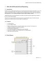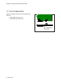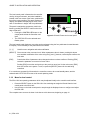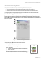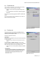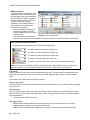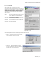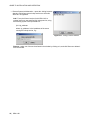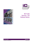
1
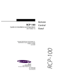
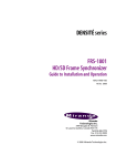
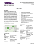
. DENSITÉ series SDA-1401 ASI DA with EQ and Reclocking Guide to Installation and Operation M826-9900-100 4 Jun 2009 Miranda Technologies Inc. 3499 Douglas-B.-Floreani St-Laurent, Québec, Canada H4S 1Y6 Tel. 514-333-1772 Fax. 514-333-9828 www.miranda.com © 2009 Miranda Technologies Inc. GUIDE TO INSTALLATION AND OPERATION Safety Compliance Information Safety Compliance This equipment complies with: - CSA C22.2 No. 60950-1-03 / Safety of Information Technology Equipment, Including Electrical Business Equipment. UL 60950-1 (1st Edition) / Safety of Information Technology Equipment, Including Electrical Business Equipment. st IEC 60950-1 (1 Edition) / Safety of Information Technology Equipment, Including Electrical Business Equipment. CAUTION These servicing instructions are for use by qualified service personnel only. To reduce the risk of electric shock, do not perform any servicing other than that contained in the operating instructions unless you are qualified to do so. Refer all servicing to qualified service personnel. Servicing should be done in a static-free environment. Electromagnetic Compatibility - This equipment has been tested for verification of compliance with FCC Part 15, Subpart B, class A requirements for Digital Devices. This equipment complies with the requirements of: EN 55022 Class A, Electromagnetic Emissions, EN 61000-3-2 & -3-3, Disturbance in Supply Systems EN 61000-4-2, -3, -4, -5, -6, -8 & -11 Electromagnetic Immunity How to contact us: For technical assistance, please contact the Miranda Technical support centre nearest you: Americas Telephone: +1-800-224-7882 e-mail: [email protected] Asia Telephone: +852-2539-6987 e-mail: [email protected] Europe, Middle East, Africa, UK Telephone: +44 (0) 1491 820222 e-mail: [email protected] China Telephone: +86-10-5873-1814 e-mail: [email protected] France (only) Telephone: +33 (0) 1 55 86 87 88 e-mail: [email protected] Visit our web site at www.miranda.com SDA-1401 GUIDE TO INSTALLATION AND OPERATION Table of Contents 1 SDA-1401 ASI DA with EQ and Reclocking..............................................................................1 1.1 1.2 1.3 1.4 2 Installation ..................................................................................................................................3 2.1 2.2 2.3 2.4 3 Unpacking ........................................................................................................................................... 3 Installation in the Densité frame.......................................................................................................... 3 Rear Panels and Connections ............................................................................................................ 3 Bypass Protection Relay ..................................................................................................................... 4 Operation ....................................................................................................................................5 3.1 3.2 3.3 3.4 4 Introduction ......................................................................................................................................... 1 Features .............................................................................................................................................. 1 Block Diagram..................................................................................................................................... 1 Front Card-edge Interface................................................................................................................... 2 Control options .................................................................................................................................... 5 Card-Edge Status LED........................................................................................................................ 5 Local control using the Densité frame control panel........................................................................... 5 3.3.1 Overview ................................................................................................................................ 5 3.3.2 Menu for local control............................................................................................................. 6 Remote control using iControl............................................................................................................. 7 3.4.1 The iControl graphic interface window................................................................................... 7 3.4.2 The Factory button ................................................................................................................. 8 3.4.3 The Status tab........................................................................................................................ 8 3.4.4 The Reclocker tab .................................................................................................................. 9 3.4.5 The Alarms tab....................................................................................................................... 9 3.4.6 The Info tab .......................................................................................................................... 11 Specifications ...........................................................................................................................13 ANNEX 1 – SDA-1401 Card Menu .................................................................................................14 SDA-1401 GUIDE TO INSTALLATION AND OPERATION SDA-1401 GUIDE TO INSTALLATION AND OPERATION 1 SDA-1401 ASI DA with EQ and Reclocking 1.1 Introduction The SDA-1401 is an ASI DA that provides up to 9 reclocked outputs with automatic equalization for up to 350 meters of cable (Belden 1694A). The amplifier also offers signal presence detection and remote reporting. The SDA-1401 includes reclocking, offering an extra level of signal integrity in long cable length applications. Rear panels with 4, 7 or 9 outputs are available to optimize frame real estate utilization. Additional protection for critical applications is provided by an optional protection bypass relay available on the 1x4, 1x7 and 1x9 rear panels. The SDA-1401 supports DVB-ASI formats and can drive up to 9 DVB-ASI outputs. The SDA-1401 also supports other compressed formats such as SMPTE-310M/DVB-SSI. . 1.2 Features • • • • • • • • One DVI-ASI input Up to 9 DVB-ASI outputs Maximum flexibility offered by 3 operation modes: single 1x4, single 1x7 and single 1x9 Automatic format detection and cable equalization Optional bypass relay protection SDI, DVB-ASI and SMPTE-310M/DVB-SSI formats supported Bit rate up to 270 Mbps; reclocker operates only on 270 Mbps signals Status LED and alarm reporting 1.3 Block Diagram SDA-1401 | 1 GUIDE TO INSTALLATION AND OPERATION 1.4 Front Card-edge Interface Status LED (see section 3.2) Select Button (see section 3.3) Status • • Select The front card-edge of the SDA-1401 incorporates two elements: SDA-1401 Select Button Status LED 2 | SDA-1401 GUIDE TO INSTALLATION AND OPERATION 2 Installation 2.1 Unpacking Make sure the following items have been shipped with your SDA-1401. If any of the following items are missing, contact your distributor or Miranda Technologies Inc. • SDA-1401 Reclocked DA Module • SDA-1401-XXX Rear Panel as ordered (see section 2.3) 2.2 Installation in the Densité frame The SDA-1401 and its associated rear connector rear panel must be mounted in a DENSITÉ frame. It is not necessary to switch off the frame’s power when installing or removing the card. • Install the rear panel with the card out of the frame, then insert the card See the DENSITÉ Frame manual for detailed instructions for installing cards and their associated rear panels. 2.3 Rear Panels and Connections Six rear panels are available for the SDA-1401 – see Figure 2.1 (2RU panels) and Figure 2.2 (3RU panels). SDA-1401-SRP SDA-1401-SRP-R SDA-1401-DRP SDA-1401-DRP-R Figure 2.1 SDA-1401 2RU rear panels SDA-1401 | 3 GUIDE TO INSTALLATION AND OPERATION Panels are available for the Densité 2RU frame, and also for the Densité 3RU frame. The 3RU versions are identified by the number 3 in the size designator portion of the part number, e.g. • SDA-1401-SRP is a 2RU version • SDA-1401-3SRP is a 3RU version Panels denoted by the suffix –R incorporate a bypass protection relay, as described in the next section. 2RU panels are available for the 1x4 configuration (single-width rear) and the 1x9 configuration (double-width rear) 3RU panels are available for the 1x7 configuration (single-width rear) • 2RU panels can be mounted in the 3RU frame if required, using mounting adapter hardware. The SDA-1401 detects the type of rear that is installed, and configures itself accordingly. In all cases, the rear panel includes: • • ASI IN – one input on a BNC connector ASI OUT – the appropriate number of outputs (4, 7 or 9) on BNC connectors Figure 2.2 SDA-1401 3RU rear panels: Left: SDA-1401-3SRP Right: SDA-1401-3SRP-R 2.4 Bypass Protection Relay A bypass protection relay is mounted on the SDA-1401-SRP-R, SDA-1401-DRP-R and SDA-1401-3SRP-R rear panels. The 1st output BNC is tied to the input via the non-latching relay which receives its power from the SDA-1401 card. The relay will trip upon detection of loss of card power, either through supply failure or removal of the card from the Densité frame. The relay enables the following functions • Bypass the electronic circuit • Protect the output when power is lost • Protect the output when card is removed from the frame 4 | SDA-1401 GUIDE TO INSTALLATION AND OPERATION 3 Operation 3.1 Control options The SDA-1401 can be controlled in two different ways: • The local control panel and its push-buttons can be used to move through a menu of parameters and to adjust parameter values (see section 3.3) • Miranda’s iControl system can be used to access the card’s operating parameters from a remote computer, using a convenient graphical user interface (GUI). (see section 3.4) 3.2 Card-Edge Status LED The status monitor LED is located on the front card-edge of the SDA-1401, and is visible through the front access door of the DENSITÉ frame. This multi-color LED indicates the status of the SDA-1401 by color, and by flashing/steady illumination. The chart shows how the various error conditions that can be flagged on the SDA-1401 affect the LED status. • If a cell is gray, the error condition cannot cause the LED to assume that status • If more than one LED status is possible for a particular error condition, the status is configurable. See Section 3.4.5 for details. • The factory default status is shown by a The LED will always show the most severe detected error status that it is configured to display, and in the chart error severity increases from left to right, with green representing no error/disabled, and flashing red the most severe error. LED Status Error Condition No errors Green Yellow Flashing Red No signal No lock (see note*) Red No rear * Note: in this case, ASI/SDI is not detected, but a DVB-SSI signal may be present If the LED is Flashing Yellow, it means that the card is selected for local control using the Densité frame’s control panel. See Section 3.3 for details. 3.3 Local control using the Densité frame control panel 3.3.1 Overview Push the SELECT button on the SDA-1401 card edge (see Section 1.4) to assign the local control panel to operate the SDA-1401. Use the control panel buttons to navigate through the menu, as described below. All of the cards installed in a Densité frame are connected to the frame’s controller card, which handles all interaction between the cards and the outside world. There are no operating controls located on the cards themselves. The controller supports remote operation via its Ethernet ports, and local operation using its integrated control panel. SDA-1401 | 5 GUIDE TO INSTALLATION AND OPERATION The local control panel is fastened to the controller card by a hinged connector, and when installed is located in the front center of the frame, positioned in front of the power supplies. The panel consists of a display unit capable of displaying two lines of text, each 16 characters in length, and five pushbuttons. The panel is assigned to operate any card in the frame by pushing the SELECT button on the front edge of that card. • • Pushing the CONTROLLER button on the control panel selects the Controller card itself. CONTROLLER ESC + - SELECT Figure 3.1 Densité Frame local control panel The STATUS LED on the selected card flashes yellow. The local control panel displays a menu that can be navigated using the four pushbuttons located beneath the display. The functionality of the pushbuttons is as follows: [+] [–] Used for menu navigation and value modification [SELECT] Gives access to the next menu level. When a parameter value is shown, pushing this button once enables modification of the value using the [+] and [–] buttons; a second push confirms the new value [ESC] Cancels the effect of parameter value changes that have not been confirmed. Pushing [ESC] causes the parameter to revert to its former value. Pushing [ESC] moves the user back up to the previous menu level. At the main menu, [ESC] does not exit the menu system. To exit, re-push the [SELECT] button for the card being controlled. If no controls are operated for 30 seconds, the controller reverts to its normal standby status, and the selected card’s STATUS LED reverts to its normal operating mode. 3.3.2 Menu for local control The SDA-1401 has operating parameters which may be adjusted locally at the controller card interface. • Press the SELECT button on the SDA-1401 front card edge to assign the Densité frame’s local control panel to the SDA-1401 • Use the keys on the local control panel to step through the displayed menu to configure and adjust the SDA-1401 The complete menu structure is shown in the Annex to this document, beginning on page 14. 6 | SDA-1401 GUIDE TO INSTALLATION AND OPERATION 3.4 Remote control using iControl The operation of the SDA-1401 may be controlled using Miranda’s iControl system. • • This manual describes the control panels associated with the SDA-1401 and their use. Please consult the iControl User’s Guide for information about setting up and operating iControl. In iControl Navigator or iControl Websites, double-click on the SDA-1401 icon to open the control panel. 3.4.1 The iControl graphic interface window The basic window structure for the SDA-1401 is shown in figure 3.2. The window identification line gives the card type (SDA-1401) and the slot number where the card installed in its Densité frame. On the left is a card status icon showing the overall alarm status. Its color in response to detected alarms is programmable; see section 3.4.5 on page 9. Figure 3.2 SDA-1401 iControl graphic interface window : The two Status Icons show the status of specific functions: Icon 1 – Control status • A: Green - Remote Control via iControl • B: Yellow - Local control using the menu Icon 2 – Input status • • 1 2 A A: Green – Signal OK [data rate reported in message area] B: Red – No signal When an icon shows an error state, a message describing the error in more detail will appear beneath the icons in the message area . B Figure 3.3 Status icons SDA-1401 | 7 GUIDE TO INSTALLATION AND OPERATION • If there are multiple errors, the error messages cycle so all can be seen • The icon whose status or error message is shown is highlighted with a mauve background In all cases, mousing over an icon will cause a more detailed description of its current status to appear in the message area. Error message cycling will resume when the cursor is no longer over an icon. The main section of the panel contains four tabs which give access to the various operating and status monitoring features of the SDA-1401. • Click on a tab to access its contents. Each of the four tabs is described individually – see sections 3.4.3 to 3.4.6. 3.4.2 The Factory button Click the Load Factory button at the bottom of the window to reset all parameters on this SDA-1401 card to factory-defined default values. 3.4.3 The Status tab The SDA-1401 can process the following signal formats: • SMPTE 259M-C (270Mbps) • DVB-ASI • SMPTE-310M/DVB-SSI This panel shows the status of the input signal and interface. Signal Status: Data Rate: Signal OK, or an error message When reclocker is ON, Signal OK indicates a 270 Mbps signal is present When reclocker is Bypassed, Signal OK indicates a signal in the range 20 to 270 Mbps is present The data rate detected at the input. Rear type: Only 270 Mbps with reclocker ON is specifically detected. In all other cases this window will show N/A. Shows the type of rear panel installed in the Densité frame for this SDA-1401. Figure 3.4 Status panel 8 | SDA-1401 GUIDE TO INSTALLATION AND OPERATION 3.4.4 The Reclocker tab Use the pulldown in this panel to set the SDA-1401’s reclocker operating mode for DVB-ASI signals at 270 Mbps: • Bypass – the input clock timing is passed through to the output • On – the data stream is reclocked as it passes through the SDA-1401 Reclocking is automatically bypassed for SMPTE 310M/DVI-SSI signals. The card automatically provides equalization for up to 350 m of Belden 1694A cable at 270 Mbps. Figure 3.5 Reclocker tab 3.4.5 The Alarms tab This panel allows the alarm reporting of the SDA-1401 to be configured. The panel opens in a new window when the button is clicked, and can be resized if needed. The panel is organized in columns. Status/Name This contains an expandable tree listing all the alarms reported by this SDA-1401 card. • Each alarm name includes an icon that shows its current status The Overall alarm and GSM contribution columns contain pulldown lists that allow the level of contribution of each individual alarm to the alarm named in the column heading to be set. • Click on the icon to see the pulldown showing the available levels • Overall Alarm This column allows configuration of the contribution of each individual alarm to the Overall Alarm associated with this card. The Overall Alarm is shown in the upper left corner of the iControl panel, and also appears at the bottom of the Status/Name column. Figure 3.6 Alarms tab SDA-1401 | 9 GUIDE TO INSTALLATION AND OPERATION • GSM Contribution This column allows configuration of the contribution of each individual alarm to the GSM Alarm Status associated with this card. GSM is a dynamic register of all iControl system alarms, and is also an alarm provider for external applications. The possible values for this contribution are related to the Overall alarm contribution: • If the Overall alarm contribution is selected as Disabled, the GSM alarm contribution can be set to any available value Figure 3.7 Alarm Config panel • If the Overall alarm contribution is selected as any level other than disabled, the GSM contribution is forced to follow the Overall Alarm. Levels associated with these alarms: The pulldown lists may contain some or all of the following options: The alarm makes no contribution (black icon) The alarm is of minor importance (yellow icon) The alarm is of major importance (orange icon) The alarm is of critical importance (red icon) The alarm exists but has no effect (used for text and composite alarms) Shortcut: if you click on “Set All” beside a major heading in the Status/Name column, you will open a pulldown that lets you assign a level to all alarms in that section of the column simultaneously. Log Events iControl maintains a log of alarm events associated with the card. The log is useful for troubleshooting and identifying event sequences. Click in the checkbox to enable logging of alarm events for each individual alarm. At the bottom of the window are several other controls Copy to other cards Click this button to open a panel that allows the alarm configuration set for this card to be copied into another SDA-1401 card. Get alarm keys Click this button to open a save dialog where you can save a file containing a list of all alarms on this card and their current values, along with an Alarm Key for each. The alarm keys are useful for system integration and troubleshooting. • The file is saved in Excel.csv format OK, Apply, Cancel • OK accepts the settings and closes the window once the card confirms that there are no errors. • Apply accepts the settings, but leaves the window open • Cancel closes the window without applying any changes, and leaves the previous settings intact. 10 | SDA-1401 GUIDE TO INSTALLATION AND OPERATION 3.4.6 The Info tab When the SDA-1401 is included in an iControl environment, certain information about the card should be available to the iControl system. The user can enter labels and comments that will make this card easy to identify in a complex setup. This information is entered via the Info control panel. This panel also shows other information about the card. Label: type the label that appear for this SDA-1401 when it appears in iControl applications Short Label type the short-form label that iControl uses in some cases (8 characters) Source ID type a descriptive name for this SDA-1401 Comments: type any desired text Figure 3.8 Info tab The remaining data boxes show manufacturing information about this card. • Details…: Reports the Firmware version, service version, and panel version for this card Figure 3.9 Details window • Advanced…: Shows the Miranda LongID for this card. The Miranda LongID is the address of this SDA-1401 in the iControl network. Figure 3.10 Advanced window SDA-1401 | 11 GUIDE TO INSTALLATION AND OPERATION • Remote System Administration – opens the Joining Locators data box, which lists remote lookup services to which this SDA-1401 is registered. Add: Force the iControl service for this SDA-1401 to register itself on a user-specified Jini lookup service, using the following syntax in the Input data box: jini://<ip_address> where <ip_address> is the ip address of the server running the lookup service, e.g.: Figure 3.11 Joining Locators window Remove: select one of the services listed in the window by clicking on it, and click Remove to delete it from the window. 12 | SDA-1401 GUIDE TO INSTALLATION AND OPERATION 4 Specifications INPUT Signal SMPTE-259M-C (270Mbps) EN 50083-9 DVB-ASI (270Mbps) DVB-SSI/SMPTE-310M Connector BNC per IEC 60169-8 Amendment 2 Cable Length 350 m (1150’) @ 270Mbps with Belden 1694A or equivalent Return loss: > 15 dB up to 270Mbps OUTPUTS Number of Outputs Up to 9 Signal SMPTE-259M-C (270Mbps) EN 50083-9 DVB-ASI (270Mbps) DVB-SSI/SMPTE-310M Connector BNC per IEC 60169-8 Amendment 2 Signal Level 800mV nominal DC offset 0V +/-0.5V Return Loss > 15 dB up to 360Mbps Jitter < 0.2 UI p-p (Wideband) PROCESSING PERFORMANCE Signal path: 10 bits Processing delay: <10.5 ns (reclocking), <2.5 ns (bypass) Power: TBD PHYSICAL SPECIFICATIONS Height: 3” (76mm) Length: 10” (254mm) Connection: 5 (2RU single) or 7 (3RU single) or 10 (2RU double) BNC connectors SDA-1401 | 13 GUIDE TO INSTALLATION AND OPERATION ANNEX 1 – SDA-1401 Card Menu STATUS * NO SIGNAL, NO LOCK, SIGNAL 270 Mbps, SIGNAL OK NO REAR, SRP REAR, SRP-R REAR, DRP REAR, DRP-R REAR, 3SRP REAR, 3SRP-R REAR RECLOCKER ON, BYPASS CONFIG ALARMS NO SIGNAL NO LOCK VERSION xxx FACTORY DEFAULT [RESTORE] ALARM LEVEL [GREEN, YELLOW, RED, FLASH RED] ALARM REPORT [NONE, GPI] ALARM LEVEL [GREEN, YELLOW, RED, FLASH RED] ALARM REPORT [NONE, GPI] Note: * SIGNAL OK is visible only when the DA is in a Reclocker bypass mode ** NO LOCK is visible only when the reclocker is ON. 14 | SDA-1401 **