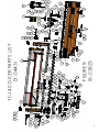
1
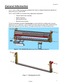
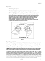
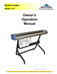
I6-03923 Proudly built in the USA Owner’s Manual TC- 140 D-ICER PLUS FOR ONE-TONS TruckCraft Corporation Chambersburg, PA 6/30/10 1-800-755-3867 Copyright c 2007 I6-03923 TRUCKCRAFT CORPORATION 5751 Molly Pitcher Hwy. S. Chambersburg, Pa. 17201 Phone: 800.375.3867 or 717.375.2900 Fax: 717.375.2975 www.truckcraft.com Contents Contents ……………………………………………………………………1 Preface ………………..…………………………………………………….2 Ordering Repair Parts ……………………………………………………2 General Information ……………………………………………………...3 Operating Instructions .…………………………………………………..4 Maintenance ………………………………………………………………..6 Installation Instructions for TC-140 D-ICER ………………………….7 Installing the Tailgate Replacement Unit ……………………………..7 Installing the Spinner Unit ………………………………………………8 Installing the Electronic Controls ……………………………………...9 Wiring Harness Routing ………………………………………………..10 Parts List …………………………………………………………………..11 Warranty ……………………………………………………………………13 1 6/30/10 I6-03923 TRUCKCRAFT CORPORATION " 5751 Molly Pitcher Hwy. S. Chambersburg, Pa. 17201 Phone: 800.375.3867 or 717.375.2900 Fax: 717.375.2975 www.truckcraft.com " WHERE WORKMANSHIP IS EVERYTHING Preface Read this manual carefully and follow its recommendations. This manual contains information for the installation, operation, and maintenance of the TruckCraft TC-140 D -ICER unit. Proper care and operation of the spreader will assure years of dependable service. Your local TruckCraft Dealer will instruct you in its general operation. Please have all operators carefully read this manual thoroughly before using equipment and keep it for reference. TruckCraft Corporation will be glad to answer any questions that may arise regarding the operation of your spreader. Ordering Repair Parts: When service is necessary, your local TruckCraft dealer can provide the assistance you need. If you cannot locate a dealer near you, contact TruckCraft Corporation. Always obtain original TruckCraft replacement parts from your dealer, substitute items could affect the performance and warranty of the unit. When ordering parts for the Model TC-140 have unit serial number, ECU serial number and description, or part number, of parts required. The unit serial number is located on the bottom right side of the spreader. The ECU serial number is located on the back of the unit in the upper right hand corner-10 digit number. Unit Serial Number: ___________________________ ECU Serial Number: ___________________________ Date of Purchase: _____________________________ Purchased From: _____________________________ TruckCraft Telephone #800.375.3867 or 717.375.2900 TruckCraft Fax #717.375.2975 Method of shipping parts to be specified such as customer pickup, UPS, Common Carrier, Parcel Post or Air Freight. All orders to be confirmed in writing, or faxed, to insure proper understanding of request. Having preventative maintenance parts on hand could save you valuable time. Improvements and Changes Because TruckCraft strives to continually improve our products, we reserve the right to make changes and improvements wherever practical, without obligation to make those same changes or improvements to the equipment already sold. Photographs used in this manual may not be up-to- date with current design changes. 6/30/10 2 I6-03923 General Information The TC-140 D-ICER Plus has been designed to be used as a tailgate replacement spreader on dump trucks up to 15,000 GVWR . The TC-140 D-ICER Plus consists of four independent components: o Tailgate replacement assembly o Spinner assembly o Mounting Bracket Kit o Electrical control system This unit is designed to handle all free-flowing ice control materials, including sand, salt, and abrasive up to ¾” in diameter. It will not break up frozen lumps and cannot force material into the auger if the material is not free flowing. The maximum flow rate is 10,000 pounds per hour. Figure 1 - TC-140 D-ICER with Access Cover Weldment removed Figure 2 – Mounting Bracket Kit 6/30/10 3 I6-03923 Operating Instructions THIS SYMBOL IS USED THOUGHOUT THIS BOOK WHENEVER PERSONAL SAFETY IS INVOLVED. TAKE TIME TO READ AND FOLLOW THE INSTRUCTIONS. BE CAREFUL! Figure 3 Observe the following safety procedures before and during use of spreader. Avoid possible injury and damage to equipment by following these rules and applying common sense. Safety: REVIEW the operating instructions that were furnished with your dump body. NEVER exceed the rating of your truck, axles, or tires. NEVER exceed the manufacturers rating of the dump bed. ALWAYS watch for overhead wires and other height limitations when driving with bed lifted. NEVER drive with the dump bed raised any more than absolutely necessary. NEVER drive with the bed lifted when road surface is not level. NEVER allow frozen clumps to get into the auger. NEVER operate the auger with the cover open. 6/30/10 4 I6-03923 Operation: Positioning the spinner Raise the bed while observing the clearance between the spinner unit and the auger housing. With the spinner unit positioned approximately as shown on “ Illustration A” Fig.4, load some deicing material in the bed for final adjustment of the spinner. Position the bed with the front bottom edge at eye level when sitting in the cab. This is the recommended operating position and the position to have the bed in when making final adjustments to the spinner location. With the bed raised to this elevation you can now run some material through the spinner and adjust the pattern to the position that you want it. Moving the spinner to the left moves the pattern clockwise and moving it to the right causes the pattern to move counterclockwise. The speed of the spinner changes the distance the material will be thrown and consequently the area to be covered. Figure 4 Spreading materi al It is recommended that you not drive the truck with the bed raised any more than is necessary, and that you be constantly vigilant in watching for overhead obstructions and wires. When the auger empties the material that flows into it, stop and raise the bed to cause more material to flow into the auger. The speed of the auger controls the volume of material being spread while the speed of the spinner controls the area that is being covered. Caution: Before starting auger and spinner make sure everyone is clear of the spreader area. Be sure power is turned off before working on or around the spreader equipment. The Electronic Control Unit (ECU) provides all the controls for the D-ICER, see Fig. 5. When preparing to spread material, push the spreader “On/Off” power button. A “V 1.02XB” (Numbers may change on ECU updates) will appear in the Menu window indicating the unit is powered up. Push the motor “On/Off” power button. A “0” will appear in the spinner and auger windows. Select the up arrow until a “4” or “5” appears in both windows. Check at the rear of the truck to make sure the spinner is turning and spreading material. With the motor selector on, push the menu button and note the following sequence of displays as the button is pushed repeatedly: 6/30/10 5 I6-03923 “12.0 BV” - Battery voltage-varies with vehicle and condition of electrical system. Note: a low battery warning will display in the menu window if voltage falls below 10 Volts. “12.0 SV” - Solenoid voltage-value should be close to BV. “100° F” - Electronic board temperature. Note: an over temperature warning will display in the menu window if temperature exceeds 180° F. “Running” “10 60 I” - Spinner amperage first; auger amperage second. Note: an over current warning will display in the menu window if auger current exceeds 70 A. or spinner current exceeds 35 A. Routine stopping and starting of the spinner and auger should be performed by pushing the motor “On/Off” button. Note: Using this method, the speed settings are retained by the controller and when the button is pushed to restart, the motors are returned to their previous speeds. Figure 5 with spinner/auger amperage shown Screened material should be used whenever possible to avoid clogging the auger. If a jam occurs the ECU motor speeds will flash and an auger over current warning will display in the menu area of the ECU. If this occurs, lower the dump body and push the motor “On/Off” button to shut the system down. Unplug the auger power cable from the motor harness. The plug is located at the rear of the truck on the driver’s side. Warning: Always unplug the auger before attempting to clear a clog. Accidental starting of the auger could result in serious injury. Raise barrel bolt latches on access cover and raise cover for access to the jam. A pipe wrench can be used to turn the auger in the reverse direction to assist in cleaning the jam. Close the cover and latch prior to plugging the auger motor back into the harness. Maintenance Auger bearings Once per season add a small amount of grease slowly to each bearing. Take care to not add the grease to fast or it will dislodge the end covers. Roller Chain Spray periodically with a high quality chain lubricant such as PJ1 Blue Label Chain Lube or equivalent. Entire unit At the end of the season do a thorough wash down and cleaning prior to storing the unit for the summer. 6/30/10 6 I6-03923 Installation Instructions for TC-140 D-ICER: Installing the Tail gate Replacement Unit The TC-140 D-ICER Plus is designed for use on dump trucks up to 15,000 GVWR. (See Parts List, Figure 9 & 10, at end of manual for details) Step #1. Measure the overall width of the dump body tailgate at the bottom not including the latching pins. ? Subtract this dimension from 90”. The remainder represents the amount that must be cut off of the lower channel of item #78 (Bracket R.H.) in Figure 9. With this material removed, fit item #78 (Bracket R.H.) together with item #77 (Bracket L.H.) and measure the overall width. Be sure to measure to the outside of items #75 in order for the bracket assembly to fit properly. Step #2 Once the correct width of the bracket assembly is established, the R.H. and L.H. sides must be connected. This is accomplished by transferring the hole locations in the splice channel on item #77 (Bracket L.H.) to the underside of the lower channel on item #78 (Bracket R.H.). With these holes located, drill (2) 5/16” holes and bolt the brackets together using the fasteners provided. Step #3 Select (2) pins approximately the same diameter as the lower pins on the existing tailgate and install them to the pin bars (item #75) as shown in Figure 9. Do not fully tighten until the proper position is established in step #4. Step #4 With the dump body tailgate removed; position the bracket assembly against the back of the dump bed. Adjust the position of the pins so that the top of the horizontal channel is flush with the dump bed floor. Tighten the bolts. Step #5 While the bracket assembly is still in position on the back of the dump bed, determine whether mounting bars (item #74) or pins (items #71 or #72) are to be used at the top of the bracket assembly. After determining the proper parts to be used, holes will need to be drilled in the vertical columns of the brackets for installation of the mounting bars or pins. If the mounting bars (item #74) are used, it may be necessary to cut off any excess material protruding past the back of the bracket assembly This can be determined in step #7 when it is fitted to the D-ICER housing. If the mounting bars hit the D-ICER housing the excess material will have to be sawed off. Warning: In all cases where pins (items #70, 71, or 72) are being used, Locktite must be used on the threads of the bolts attaching these pins. 6/30/10 7 I6-03923 Connecting the Bracket Assembly to the D-ICER Step #6 Bolt the (2) bent plates (item #76) to the bracket assembly as shown on drawing Step #7 Remove the bracket assembly from the dump bed and lay it on a work surface with the bent plates pointing up. Lay the D-ICER on top of the bracket assembly. With the lid of the D-ICER open, position the D-ICER so that the floor surface (under the auger) is flush with the top of the horizontal channels on the bracket assembly. Center the D-ICER on the bracket assembly. Step #8 In the aluminum angle at the bottom of the D-ICER there are (2) 9/16” holes at each end. Mark the locations of these holes onto the horizontal channels of the bracket assembly and drill matching holes. Using the fasteners provided attach the D-ICER to the mounting frame. Step #9 On the top of the D-ICER where the bent plates (item #76) are located, drill (4) holes through the D-ICER housing using the holes in the plates as guides. Use the fasteners provided to attach. Installing the Spinner Unit (See Parts List, Figure 9 & 10, at end of manual for details) Open the Auger Access cover and locate the four holes in the bottom plate. Align these holes with the mount holes in the spinner support bracket. Bolt the spinner in place. The spinner can be adjusted front to back by relocating the pin in the slide mount holes. Slotted holes in the support bracket provide side to side adjustment. Plug the spinner motor cord into the motors harness. Figure 6 6/30/10 8 I6-03923 Installing Electronic Control and Wiring Harnesses (See Figure 8, Drawing C2 -04310) Step #1 Find a suitable location for the Electronic Control Unit Assembly (ECU Assembly) C204227, (ECU is C4-03879) in the cab. A good location is over the transmission with the bracket bolted to the floor or to the underside of the dash. CAUTION: Do not mount unit in the deployment path of the air bags. Step #2 Install the Power Harness B4-04221, Figure 10, Item 1 in the engine compartment. This harness includes a black box that contains a solenoid for turning the main ECU power on and off. The box also includes a 125 amp fuse for protection of the main power wiring. Install the harness with the black box located close to the battery. Do not attach the four wire lugs to the battery until all other wiring is installed. Attach the wiring harness to existing wiring, brackets, or other non-moving parts in the engine compartment. Do not attach or get the wiring harness near heat generating components. Find a location on the firewall to run the wiring through. An existing opening with a rubber grommet is preferred. Most truck manufacturers provide an opening for this purpose and locate it near the fuse box under the dash. Step #3 Install the Motors Wiring Harness B4-04222, Item 2. At the rear of the truck on the driver’s side find a suitable location to mount the bracket, Item 97, to hold the plugs at that end of the wiring harness. This stainless steel bracket does not need to be painted. Use the holes in the bracket to locate (2) 3/16” diameter drilled holes to mount the bracket to the truck. Make sure the location is easily accessible and within reach of the power cords attached to the auger and spinner motors. Do not locate the plugs in an area where snow, mud and ice accumulate from tire spray. Run the harness along the truck frame beneath the deck and into the cab. Assure that the wiring harness does not contact any sharp objects and is not located too near any heat sources. Step #4 Plug the ends of both wiring harnesses into the back of the ECU unit in the cab as shown below. Step #5 Plug the auger and spinner power cords into the plugs on the Motors Harness. Connect the positive and negative wires to the battery in the engine compartment. Step # 6 Make sure that no one is near the D-ICER prior to turning the power on. Check out the function of the unit per the “Operation” section of this manual. Control Plug from Engine Harness Auger plugs on Motor Harness Power from Engine Harness Spinner Plugs on Motor Harness Figure 7 6/30/10 9 Power from Engine Harness 10 Battery _ Battery + - A 125 Amp Fuse Power On / Off Control Wire to ECU #16 ga. Red + Black #4 ga. Power On / Off Ground Wire to ECU #16 ga. Black Black #16 ga. Red #4 ga. Ground to Control Unit #4 ga. Black Red #16 ga. DETAIL A Black #16 ga. Black Box Red #4 ga. Control Solenoid Power Harness Power to Control Unit #4 ga. Red ECU Figure 8 I6-03923 See D-ICER Assembly Bill of Material for ECU, Harness and Cable Part Numbers. Plan View of Truck DETAIL B DATE: MATERIAL: B SHEET SCALE: 1 OF 1 APPR. BY: DATE C2-04310 FAX 717-375-2975 GEL DRAWN BY: DWG. NO. 717-375-2900 Chambersburg, PA. 17201 5751 Molly Pitcher Highway Spinner Motor Cable Supplied with Motor Spinner Motor WIRING HARNESS ROUTING See Parts List 10/25/06 NONE TITLE: 1. REMOVE ALL BURRS, CHAMFER, OR RADIUS CORNERS. 2. TOLERANCES UNLESS OTHERWISE SHOWN: DECIMALS TWO PLACES .00 ±.030 THREE PLACES .000 ±.005 ANGLES ±1° 3. DO NOT SCALE DRAWING. Auger RD/WE & WE/BK - #6 ga. Motors Harness Spinner WE & BK - #10 ga. ECU Assembly Auger Motor Cable REVISIONS Auger Motor 50 71 54 81 48 45 85 88 87 80 49 39 33 77 76 66 67 68 69 52 56 45 77 79 76 11 83 38 40 42 73 94 36 84 45 52 57 55 5 75 47 37 48 86 52 56 45 93 9 72 82 39 99 43 51 74 30 7 78 79 76 35 25 24 12 10 11 19 FIGURE 9 I6-03923 46 44 41 53 51 21 23 22 5 98 75 5 22 34 8 29 TC-140 D-ICER PARTS LIST D1-04431 26 27 4 68 3 64 28 31 32 45 61 67 59 58 62 21 5 22 70 58 92 89 62 65 90 20 63 52 96 60 16 13 91 15 14 6 18 17 5 22 21 5 23 23 22 21 76 5 77 Item 1 2 3 4 5 6 7 8 9 10 11 12 13 14 15 16 17 18 19 20 21 22 23 24 25 26 27 28 29 30 31 32 33 34 35 36 37 38 Part # B4-04221 B4-04222 I6-03923 B4-00708 P4-00567 P4-00896 B4-01790 A4-00720 P4-00821 P4-00832 P4-00833 P4-00834 A4-00825 A4-00823 A4-00824 A4-00822 A4-00794 P4-03547 A4-00838 B4-00816 P4-00615 P4-00570 P4-00879 A4-03248 P4-01907 P4-00885 P4-00884 A4-03261 A4-00837 B4-04184 A4-00839 A4-00840 A4-00793 C3-04422 C3-04428 C3-01785 C4-04172 C4-04173 Qty 1 1 1 2 23 1 1 2 1 8 8 8 1 1 1 1 1 24 1 1 16 28 14 3 12 2 2 1 1 1 1 1 1 1 1 1 1 1 Name Power Harness / TC-160 Motors Harness Installation Instructions Seal Plate Nyl. Insert Lock Nut - .38-16 SS Hex Head Cap Screw Hinge Detail Slinger Spiral Retaining Ring / External Hex Hd Cap Screw - .44-14 X 2.25 SS Nyl. Insert Lock Nut - .44-14 SS Flat Washer - .44 SS Key - .25 SQ X 1.25 SS Sprocket / Auger / 1.25" Shaft Dia. Roller Chain Sprocket/Gearmotor/.75" Shaft Dia. Bearing 1.25 W/ Open Cap/4 Bolt Rivet, .19 SS/Magna-Lok (Short) Decal / Warning / Spinner Gearmotor Mounting Bar Hex Head Cap Screw Flat Washer - .38 SS Flat Washer Barrel Bolt Pop Rivet Nyl. Insert Lock Nut - .31-18 SS Hex Head Cap Screw Grab Handle / Aluminum Decal / D-ICER Large LOGO Decal - 3D Effects Decal / Danger / Sprockets Decal / Danger / Auger Bearing 1.25 W/Closed End/4 Bolt Housing Weldment Access Cover Weldment Auger Weldment Spinner Hsg.-Top Spinner Hsg.-Bottom Item 39 40 41 42 43 44 45 46 47 48 49 50 51 52 53 54 55 56 57 58 59 60 61 62 63 64 65 66 67 68 69 70 71 72 73 74 75 76 Part # P4-02787 B4-04174 B4-04178 D4-04155 B4-04252 P4-00465 P4-00557 B4-04270 P4-04311 P4-03919 C4-04271 B4-04305 A4-01440 P4-00566 B4-04267 P4-03546 C4-04419 P4-00569 D4-04154 A4-03274 A4-04303 P4-02406 B4-04250 P4-03792 P4-02376 C4-03879 C4-04226 A4-02316 A4-02317 A4-02318 A4-02340 B4-02314 B4-02315 B4-02337 C3-02320 C3-02335 P4-00562 P4-00620 Qty 7 1 1 2 1 4 20 2 2 4 1 1 4 18 1 2 1 20 1 2 2 6 2 6 2 1 1 2 4 4 2 2 2 2 1 1 6 16 Name Pan Hd Sht Metal Screw - #12 X .75 SS End Plate / Spinner Housing / TC-160 End Plate / Cord Grip End Support Leg -Spinner Mt Spinner Mtg Pin / .75 OD x 10.0"lg Hex Hd Cap Screw - .25-20 X 1.25 SS Hex Hd Cap Screw-.25-20 X.75 SS Spacer-Spinner Motor / Housing Hex Hd Cap Screw - .25-20 X .625 SS Hex Serrated-Flange Nut .25-20 Brace- Spinner Shield Support Deflector Hairpin Nyl. Insert Lock Nut - .25-20 SS Pin- Spinner Brkt. Mtg / .50 OD x 10.0"lg Magna-Lok S/S (Long) - .19 SS RIVET Spinner Support Bracket, TC-140 Flat Washer - .25 SS Slide Mount -Spinner Bar Knob / ECU Flat Washer - .25 Zinc Pl. Side Brace / ECU Mtg Carriage Bolt - .25-20 x .75" SS Hex Wshr Hd Thd Frmng Scr-.25-14 x .75 Electronic Controller/D-Icer Bottom - Bracket Pin .75"Ø Pin 1.00"Ø Pin 1.25"Ø Plate / Fastener Mounting Bar Pin Bar Bent Plate Bracket LH Bracket RH Hex Hd Cap Screw - .38-16 X1.0 SS Flat Washer - .50 SS Item 77 78 79 80 81 82 83 84 85 86 87 88 89 90 91 92 93 94 95 96 97 98 99 Part # P4-00687 P4-00689 P4-00836 B2-04176 B4-04258 P4-03974 P4-02785 A4-04319 P4-00883 P5-05741 A4-01494 A4-01493 A4-02659 A4-04302 P4-03567 B4-04315 C4-04225 D4-04533 A4-02401 P5-05742 P4-04542 A4-04572 A2-02416 Qty 8 2 6 1 1 1 1 1 2 1 1 1 1 1 1 1 1 1 1 4 1 1 1 I6-03923 12 Name Hex Hd Cap Screw - .50-13 X 1.50 SS Hex Hd Cap Screw - .50-13 X 1.25 SS Nyl. Insert Lock Nut - .50-13 SS Spinner Plate Assembly-for 1/6hp Motor Bevel Gear Reducer /2:1/ Zero Max Motor - 1/6HP - 12vdc Felt Washer 1/4"thk x 3/4"IDx 1 1/4"OD KEY .19 x .19 x .625" lg SS Cup Point Set Screw .25-20 x .38 SS Coupling, Single Disc Cap - 3/4" KEY - .19 SQ x 1.00 SS Gearmotor Cord Grip Ftg/Stgt Grommet, Blck Rbr .44 ID Cable-Auger Motor, 12ft Bracket / Deutsch-Delphi Plugs Brace Decal / PLUS Cup Point Set Screw .31-18 x .50 SS Cap, Vinyl Decal / Box Not Watertight Spinner Plug Assembly D1-04431 TC-140 D-ICER PARTS LIST - FIGURE 10 13 TruckCraft Corporation warranty. 5751 Molly Pitcher Hwy. S., Chambersburg, PA 17201 Printed in U.S.A. oc 2010 TruckCraft Corp. make any representation or promise on behalf of TruckCraft, or to alter or modify the terms or limitations of this dealer. No claims for labor shall be considered unless preauthorized by TruckCraft. No dealer has authority to authorized by TruckCraft. This warranty does not cover the shipping costs of defective parts to or from the claims by the user must be made to the dealer from which the product was purchased, unless otherwise failures due to lack of maintenance or accidents. TruckCraft does not warrant against corrosion. Warranty of the foregoing warranty. Warranty will not be considered on any altered, modified, or misused part and required following improper use or application of any products shall not be considered defects within the scope Installation and operation of the product must be in accordance with TruckCraft’s instructions. Repairs to correct the defect. TruckCraft is notified of such defect or defects within the Two Year warranty period and given reasonable time its own expense, any part or parts of the product found to be defective in material or workmanship, provided period of Two Years from the date of sale to the original retail purchaser and agrees only to repair or replace at TruckCraft Corporation warrants each D-ICER to be free from defects in material and workmanship for a Warranty