1
37387
DTSC-200
ATS Controller
Operation
Software Version 1.0xxx
Manual 37387
Manual 37387
DTSC-200 - ATS Controller
WARNING
Read this entire manual and all other publications pertaining to the work to be performed before installing, operating, or servicing this equipment. Practice all plant and safety instructions and precautions.
Failure to follow instructions can cause personal injury and/or property damage.
The engine, turbine, or other type of prime mover should be equipped with an overspeed (overtemperature, or overpressure, where applicable) shutdown device(s), that operates totally independently of the
prime mover control device(s) to protect against runaway or damage to the engine, turbine, or other
type of prime mover with possible personal injury or loss of life should the mechanical-hydraulic governor(s) or electric control(s), the actuator(s), fuel control(s), the driving mechanism(s), the linkage(s),
or the controlled device(s) fail.
Any unauthorized modifications to or use of this equipment outside its specified mechanical, electrical,
or other operating limits may cause personal injury and/or property damage, including damage to the
equipment. Any such unauthorized modifications: (i) constitute "misuse" and/or "negligence" within
the meaning of the product warranty thereby excluding warranty coverage for any resulting damage,
and (ii) invalidate product certifications or listings.
CAUTION
To prevent damage to a control system that uses an alternator or battery-charging device, make sure
the charging device is turned off before disconnecting the battery from the system.
Electronic controls contain static-sensitive parts. Observe the following precautions to prevent damage to these parts.
•
Discharge body static before handling the control (with power to the control turned off, contact a
grounded surface and maintain contact while handling the control).
•
Avoid all plastic, vinyl, and Styrofoam (except antistatic versions) around printed circuit boards.
•
Do not touch the components or conductors on a printed circuit board with your hands or with
conductive devices.
OUT-OF-DATE PUBLICATION
This publication may have been revised or updated since this copy was produced. To verify that you
have the latest revision, be sure to check the Woodward website:
http://www.woodward.com/pubs/current.pdf
The revision level is shown at the bottom of the front cover after the publication number. The latest
version of most publications is available at:
http://www.woodward.com/publications
If your publication is not there, please contact your customer service representative to get the latest
copy.
Important definitions
WARNING
Indicates a potentially hazardous situation that, if not avoided, could result in death or serious injury.
CAUTION
Indicates a potentially hazardous situation that, if not avoided, could result in damage to equipment.
NOTE
Provides other helpful information that does not fall under the warning or caution categories.
Woodward reserves the right to update any portion of this publication at any time. Information provided by Woodward is believed to be
correct and reliable. However, Woodward assumes no responsibility unless otherwise expressly undertaken.
© Woodward
All Rights Reserved.
Page 2/31
© Woodward
Manual 37387
DTSC-200 - ATS Controller
Revision History
Rev. Date
NEW 07-12-12
Editor
TP
Changes
Release
Content
CHAPTER 1. GENERAL INFORMATION..........................................................................................5
Related Documents.................................................................................................................................5
CHAPTER 2. NAVIGATION / OPERATION.......................................................................................6
Navigation ...............................................................................................................................................7
Operation ..............................................................................................................................................11
Operation Display .......................................................................................................................12
Timer Display ..............................................................................................................................12
Navigation ...................................................................................................................................13
LogicsManager ...........................................................................................................................14
CHAPTER 3. FUNCTIONAL DESCRIPTION ...................................................................................15
General ATS Functionality ....................................................................................................................15
Application Modes.................................................................................................................................16
Util-Util Application Mode............................................................................................................16
Util-Gen Application Mode ..........................................................................................................16
Gen-Gen Application Mode ........................................................................................................16
Blocking Transfer Operations ...............................................................................................................17
LogicsManager function "Inhibit ATS" ........................................................................................17
Switch Failures............................................................................................................................17
Mechanical Failure (Limit Switch Monitoring) .............................................................................18
CHAPTER 4. CONFIGURATION ...................................................................................................23
Structure of the Parameters..................................................................................................................23
Parameters............................................................................................................................................25
Language ....................................................................................................................................25
Password ....................................................................................................................................25
Display Contrast .........................................................................................................................25
Deactivate Horn ..........................................................................................................................25
Code Levels ................................................................................................................................26
Password ....................................................................................................................................26
Factory (Default) Values .............................................................................................................26
Real-Time Clock - Time ..............................................................................................................27
Real-Time Clock - Date ..............................................................................................................27
Version........................................................................................................................................27
APPENDIX A. MESSAGES .........................................................................................................28
Timer / Operation States .......................................................................................................................28
Alarm Messages ...................................................................................................................................30
© Woodward
Page 3/31
Manual 37387
DTSC-200 - ATS Controller
Illustrations And Tables
Illustrations
Figure 2-1: Front panel and display ........................................................................................................................................... 6
Figure 2-2: Screen - Level overview........................................................................................................................................ 11
Figure 3-1: General ATS functionality - flowchart.................................................................................................................. 15
Figure 3-2: Limit switch monitoring - failure message............................................................................................................ 18
Tables
Table 1-1: Manual - Overview................................................................................................................................................... 5
Table 3-1: Limit switch monitoring - truth table for "Standard" limit switch w/o "Open" replies........................................... 19
Table 3-2: Limit switch monitoring - truth table for "Delayed" limit switch w/o "Open" replies ........................................... 20
Table 3-3: Limit switch monitoring - truth table for "Open" limit switch with "Open" replies ............................................... 22
Table 4-1: Timer / operation states - display ........................................................................................................................... 29
Page 4/31
© Woodward
Manual 37387
DTSC-200 - ATS Controller
Chapter 1.
General Information
Related Documents
≡≡≡≡≡≡≡≡≡≡≡≡≡≡≡≡≡≡≡≡≡≡≡≡≡
Type
DTSC-200 Series
DTSC-200 - Installation
DTSC-200 - Configuration
DTSC-200 - Operation
DTSC-200 - Application
DTSC-200 - Interfaces
Additional Manuals
IKD 1 - Manual
this manual
English
German
37385
37386
37387
37388
37389
-
37135
GR37135
Discrete expansion board with 8 discrete inputs and 8 relay outputs that can be coupled via the CAN bus to the control unit. Evaluation of the discrete inputs as well as control of the relay outputs is done via the control unit.
LeoPC1 - User Manual
37146
GR37146
PC program for visualization, configuration, remote control, data logging, language upload, alarm and user management, and management of the event recorder. This manual describes the set up of the program and interfacing with the control unit.
LeoPC1 - Engineering Manual
37164
GR37164
PC program for visualization, configuration, remote control, data logging, language upload, alarm and user management, and management of the event recorder. This manual describes the configuration and customization of the program.
Table 1-1: Manual - Overview
Intended Use The unit must only be operated for the uses described in this manual. The prerequisite for a proper
and safe operation of the product is correct transportation, storage, and installation as well as careful operation
and maintenance.
NOTE
This manual has been developed for a unit fitted with all available options. Inputs/outputs, functions,
configuration screens and other details described, which do not exist on your unit may be ignored.
The present manual has been prepared to enable the installation and commissioning of the unit. On
account of the large variety of parameter settings, it is not possible to cover every possible combination. The manual is therefore only a guide. In case of incorrect entries or a total loss of functions, the
default settings can be taken from the enclosed list of parameters at the rear of this manual.
© Woodward
Page 5/31
Manual 37387
DTSC-200 - ATS Controller
Chapter 2.
Navigation / Operation
13
14
16
15
S1
S2
1
5
2
6
12
3
7
4
8
9
10
11
17
DTSC-200
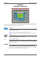
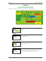
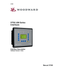
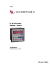
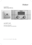
Figure 2-1: Front panel and display
Figure 2-1 illustrates the front panel/display, which includes push buttons, LEDs and the Liquid Crystal display
(LC display). A short description of the front panel is given below.
Function blocks
Buttons that have the same function within one screen are grouped into function blocks. The
function blocks are defined as:
Operation ....Used to perform manual operation of the genset (page 11).
Navigation ...Navigation between system and configuration screens, and alarm list (page 12).
1
2
3
4
5
6
7
8
9
10
11
Push buttons
The push buttons on the front panel are assigned to softkeys on the display. Each softkey is assigned to a function depending on the mode of operation.
Liquid Crystal Display (LC display)
12
The display contains softkey characters, measuring values, modes of operation, and alarms. The
functionality of the display screens as well as the description of the functions is detailed in the "
Navigation" section (page 7).
13 14 15 16
17
LEDs
The left LED 13 indicates that Source 1 is available. The second LED 14 indicates that the
switch is closed to Source 1 position. The third LED 15 indicates that the switch is closed to
Source 2 position. The right LED 16 indicates that Source 2 is available. The lower LED 17 indicates that alarm messages are active / present in the control unit.
Page 6/31
© Woodward
Manual 37387
DTSC-200 - ATS Controller
Navigation
≡≡≡≡≡≡≡≡≡≡≡≡≡≡≡≡≡≡≡≡≡≡≡≡≡
Individual display screens are listed in the following text. All softkeys, which are available in the individual
screens are described with their function.
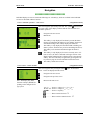
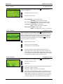
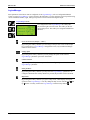
Screen "Automatic operation" / "Start screen"
[all application modes]
This screen appears upon startup of the unit. The symbol , located in the
lower left corner of the display, indicates that the ATS controller is in
automatic operation.
Navigate to the next screen
Main menu
This softkey is only displayed if an alarm is present (the alarm
message is indicated on the display). If it is flashing, the alarm is
still unacknowledged. This softkey displays the alarm list.
This softkey is only displayed if the Alarm LED is flashing (An
alarm is present, which has not yet been acknowledged as 'Seen').
This softkey resets the horn and acknowledges the alarm as
'Seen'.
This softkey is only displayed, if a timer is currently active. If a
timer is active, the timer is indicated in the upper section of the
display and the remaining time is displayed next to the "Bypass"
softkey. The active timer may be bypassed by pressing this softkey. Refer to page 28 for more information about the timers.
This softkey enables the test mode.
Screen "Source 1 values - Details"
[all application modes]
This screen appears after pressing the softkey again. All measured
source 1 values are displayed in this screen.
Navigate to the next screen
Navigate to the previous screen
Note: The display may differ
from this example (3Ph/4W) depending on the configured voltage system.
Return to the start screen
1 / 2 / 3 ......... Source 1 voltages VL1N / VL2N / VL3N
12 / 23 / 31 ... Source 1 voltages VL12 / VL23 / VL31
00.00Hz........ Source 1 frequency
................. Phase rotation clockwise 3
................. Phase rotation counterclockwise 4
© Woodward
Page 7/31
Manual 37387
DTSC-200 - ATS Controller
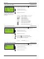
Screen "Source 2 values - Details"
[all application modes]
This screen appears after pressing the softkey again. All measured
source 2 values are displayed in this screen.
Navigate to the next screen
Navigate to the previous screen
Return to the start screen
Note: The display may differ
from this example (3Ph/4W) depending on the configured voltage system.
1 / 2 / 3..........Source 2 voltages VL1N / VL2N / VL3N
12 / 23 / 31....Source 2 voltages VL12 / VL23 / VL31
00.00Hz ........Source 2 frequency
000kW..........Source 2 real power
000kvar ........Source 2 reactive power
1.00 ...............Source 2 power factor = 1
Lg0.00 ..........Source 2 power factor (lagging)
Ld0.00 ..........Source 2 power factor (leading)
.................Phase rotation clockwise 3
.................Phase rotation counterclockwise 4
Screen "Load current slave pointer "
[all application modes]
This screen appears after pressing the softkey again. The slave pointers
show the maximum currents monitored by the control unit.
Navigate to the next screen
Navigate to the previous screen
Return to the start screen
sign: present monitored value
Left of the
sign: maximum monitored values
Right of the
Reset the maximum measured values.
1 / 2 / 3..........Load current IL1 / IL2 / IL3
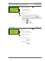
Screen "Battery voltage value - Details"
[all application modes]
This screen appears after pressing the softkey again. The measured battery voltage value is displayed graphically and numerically.
Navigate to the next screen
Navigate to the previous screen
Return to the start screen
Page 8/31
© Woodward
Manual 37387
DTSC-200 - ATS Controller
Screen "Discrete inputs / discrete (relay) outputs – Status display"
[all application modes]
This screen appears after pressing the softkey again. Discrete input and
discrete output status are displayed.
Navigate to the next screen
Navigate to the previous screen
Return to the start screen
Status display of the discrete inputs and discrete outputs.
(Note: The configured logic for the discrete input "N.O./N.C."
will determine how the easYgen reacts to the state of the digital
input. If the respective DI is configured to N.O, the unit reacts on
the energized state ( ); if it is configured to N.C., it reacts on the
de-energized state .)
energized
Discrete input:
de-energized
Discrete output: relay activated
relay de-activated
Screen "Time / Date"
[all application modes]
This screen appears after pressing the softkey again. Here the time and
date are displayed.
Navigate to the next screen
Navigate to the previous screen
Return to the start screen
0000-XXX-00 - Date
0000 = Year
XXX = Month
00 = Day
00:00:00 - Time
00 = Hour
00 = Minute
00 = Second
© Woodward
Page 9/31
Manual 37387
DTSC-200 - ATS Controller
Screen "Counters"
[all application modes]
This screen appears after pressing the softkey once more. Here the
counters are displayed.
Navigate to the previous screen
Return to the start screen
Energy 0.00 kWh - Generator real energy
0.00MWh = Total generator real energy
Pos. reactive energy 0.00 Mvar - Generator reactive energy
0.00Mvarh = Total generator reactive energy
Overlap time counter 00 ms - Overlap time
00ms = Overlap time of the last transfer
Phase angle S1-S2 000.0° - Phase angle
0000.0° = Ph. angle between source 1 and source 2
Screen "Alarm list"
[all application modes]
This screen appears after pressing the softkey in the start screen. All
alarm messages, which have not been acknowledged and cleared, are displayed. Each alarm is displayed in two lines; the first line describes the
alarm message and the second line is the date and time of the alarm occurred in the format Mon-dd hh:mm:ss.ss. The symbol indicates that
this alarm condition is still present.
Return to the start screen
Scroll up to next alarm message
Scroll down to next alarm message
The selected alarm message (displayed inverted) will be acknowledged. This is only possible, if the alarm condition is no
longer present. If the Alarm LED is still flashing (an alarm is present, which has not yet been acknowledged as 'Seen'), this softkey
resets the horn and acknowledges the alarm as 'Seen'.
Screen "Test mode"
[all application modes]
This screen appears after pressing the softkey
in the start screen.
Navigate to the next screen
Main menu
This softkey disables the test mode and returns to the start menu.
This softkey enables a load test.
This softkey enables an engine test (no load test).
This softkey is only displayed, if a timer is currently active. If a
timer is active, the timer is indicated in the upper section of the
display and the remaining time is displayed next to the "Bypass"
softkey. The active timer may be bypassed by pressing this softkey. Refer to page 28 for more information about the timers.
Page 10/31
© Woodward
Manual 37387
DTSC-200 - ATS Controller
Operation
≡≡≡≡≡≡≡≡≡≡≡≡≡≡≡≡≡≡≡≡≡≡≡≡≡
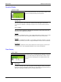
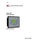
The display is partitioned into different areas to give an overview of the displayed data.
Softkeys
Messages
Timer
Operation
Softkeys
Figure 2-2: Screen - Level overview
"Operation"
The "Operation" section of the screen shows the current status of the
sources.
"Messages"
The "Messages" section of the screen shows all active alarms and operations information.
"Timer
The "Timer" section of the screen indicates a count-down timer if a
timer is currently active.
"Softkeys"
The "Softkeys" permit navigation between screens, levels and functions and may be used to operate the unit. Refer to the Operation
Display section on page 12 for detailed information.
© Woodward
Page 11/31
Manual 37387
DTSC-200 - ATS Controller
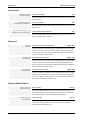
Operation Display
"Operation" display
The current operation state of the unit and the condition of the
sources are displayed during normal operation.
Operation state
The current operation state of the unit is indicated in the "Messages" section of the
screen. Refer to Appendix A: Messages on page 28 for a list of the possible operation
states.
Source condition
The current source condition is indicated in the "Operation" section of the screen. The
following source conditions are possible:
S1/2 Ok
Source 1/2 is considered as "OK", i.e. the voltage and frequency of Source 1/2 are within
the restore limits (refer to the Configuration Manual 37386 for more information).
S1/2 Fail
Source 1/2 is considered as "not OK", i.e. the voltage or frequency of Source 1/2 are not
within the restore limits (refer to the Configuration Manual 37386 for more information).
S1/2 Restore
Source 1/2 is considered as "OK", but the stable timer for the respective source has not
yet expired (refer to the Configuration Manual 37386 for more information).
Timer Display
"Timer" display
If a timer is active, it is indicated in the "Messages" section of
the screen and a numerical indication In the "Timer" section
counts down the remaining time in seconds before the timer
expires.
Bypass timer
If a timer is currently active, it may be bypassed with the "Bypass" softkey. This means
that the timer expires immediately and the unit proceeds with the next operation. Refer to
Appendix A: Messages on page 28 for a list of the possible timers.
Page 12/31
© Woodward
Manual 37387
DTSC-200 - ATS Controller
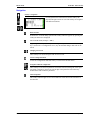
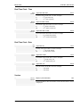
Navigation
Softkeys "Navigation"
For navigation between the main screens the softkeys displayed in the right section are used. The softkeys are assigned
with different functions.
Read alarm list
If alarms have occurred during operation this softkey character appears. By pressing this
softkey the alarm list is displayed.
Leave current screen ("Escape" / "ESC")
By pressing this softkey character you exit and go to the previous screen. If the Escape
key is used to leave a configuration screen, any unconfirmed changes made will not be
stored.
Changing screen levels
These softkeys are used to navigate from screen to screen.
Activate configuration mode
To activate configuration mode this softkey is used to enter the main menu.
Navigation within the configuration
These softkeys scroll between parameters forward or backward, change the cursor position within a parameter, increase the current digit of the parameter and confirm any
modifications made within the parameters.
Acknowledgement
This softkey acknowledges an active alarm and turns off the horn in the main menu or
the alarm list.
© Woodward
Page 13/31
Manual 37387
DTSC-200 - ATS Controller
LogicsManager
Some parameters of the DTSC-200 are configured via the LogicsManager (refer to Configuration Manual
37386). A typical LogicsManager screen is shown in the following. You may configure a logical operation using
various command variables, signs, and logical operators to achieve the desired logical output.
LogicsManager Screen
For configuration of the LogicsManager the softkeys displayed in the right section are used. The softkey on the left
opens a help screen. The softkeys are assigned with different
functions.
Leave current screen ("Escape" / "ESC")
By pressing this softkey character you exit and go to the previous screen. If the Escape
key is used to leave a LogicsManager configuration screen, any unconfirmed changes
made will not be stored.
Change option
By pressing these softkey characters you may change the option of the selected
LogicsManager parameter upwards or downwards.
Confirm selection
By pressing this softkey character you confirm the configured option of the selected
LogicsManager parameter.
Select parameter
By pressing this softkey character you may select the LogicsManager parameter to be
configured. Each time this softkey character is pressed, the parameter will be advanced.
Help button
By pressing this softkey character you get to a help screen, which displays the logical
operators of the LogicsManager. You may change the help screens with the Down and
Up buttons. You may return to the LogicsManager with the Escape button .
Page 14/31
© Woodward
Manual 37387
DTSC-200 - ATS Controller
Chapter 3.
Functional Description
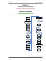
General ATS Functionality
≡≡≡≡≡≡≡≡≡≡≡≡≡≡≡≡≡≡≡≡≡≡≡≡≡
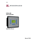
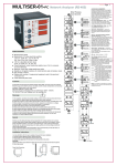
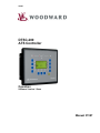
The following flowchart shows the typical ATS functionality:
Source 2 is powering the load
Source 1 is
available
Close breaker to
Source 1
No
Source 1
available ?
Source 1 is powering the load
Source 1 stable
timer expires
Source 1 fails
„S2 start delay
timer“ expires
Elevator presignal feature
On ?
Send „engine
start“ signal ( deenergize „engine
start“ relay )
No
Set elevator presignal
No
Motor load
disconnect
feature ON ?
Source 2
available ?
No
Set motor load
disconnect signal
Yes
Source 2 stable
timer expires
Perform transfer to
Source 1
Motor load
disconnect
feature ON ?
No
Set Motor load
disconnect signal
Perform transfer to
Source 2
De-energize
„Elevator presignal“
De-energize
„Motor Load
Disconnect“ Signal
De-energize
„Elevator presignal“
De-energize
„Motor Load
Disconnect“ Signal
Source 1 is powering the load
Engine cooldown
timer expires
Remove „engine
start“ signal
(energize Gen
start relay )
Figure 3-1: General ATS functionality - flowchart
© Woodward
Page 15/31
Manual 37387
DTSC-200 - ATS Controller
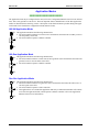
Application Modes
≡≡≡≡≡≡≡≡≡≡≡≡≡≡≡≡≡≡≡≡≡≡≡≡≡
The application mode may be configured in the unit (refer to the Configuration Manual 37386 for more information). This is only possible in code level 2. The most important features and differences of the three application
modes are illustrated in the following section. A description of the functions that are possible during each application mode can be found in the configuration manual (manual 37386).
Util-Util Application Mode
S1
This application mode has the following characteristics:
• The ATS controller monitors two mains sources and transfers the load to the secondary source in
case the primary source fails
• The ATS controller operates as Master controller
S2
Util-Gen Application Mode
S1
This application mode has the following characteristics:
• The ATS controller monitors a mains sources and a generator source and transfers the load to the
generator source in case the mains source fails
• The ATS controller operates as Master controller
G S2
Gen-Gen Application Mode
G2 S1
This application mode has the following characteristics:
• The ATS controller monitors two generator sources and transfers the load to the other source in
case the regular source fails
• The ATS controller operates as Slave controller
• This application is not a stand-alone application and always combined with another ATS controller in Util-Gen application mode, which operates as Master controller (refer to the Application
Manual 37388 for more information)
G1 S2
Page 16/31
© Woodward
Manual 37387
DTSC-200 - ATS Controller
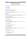
Blocking Transfer Operations
≡≡≡≡≡≡≡≡≡≡≡≡≡≡≡≡≡≡≡≡≡≡≡≡≡
The following conditions result in blocking all transfer operations. This means that the LogicsManager flags
•
•
•
•
20.07 "Close to S1"
20.09 "Close to S2"
20.08 "Open from S1"
20.10 "Open from S2"
are not enabled anymore. This blocks all transfer operations!
LogicsManager function "Inhibit ATS"
If the LogicsManager function "Inhibit ATS" (parameter 12600) is TRUE, all transfers are blocked! Refer to the
Configuration Manual 37386 for a description of this parameter.
Switch Failures
Depending on the configured "Transfer switch type" (parameter 3424), all transfers are blocked if specific switch
failures occur. Refer to the Configuration Manual 37386 for a description of this parameter.
Transfer Switch Type "Standard"
If one of the following failure conditions is present, all transfer operations are blocked and the respective failure
must be acknowledged before a new transfer is possible:
• Fail to close S1 is present
• Fail to close S2 is present
Transfer Switch Type "Delayed"
If one of the following failure conditions is present, all transfer operations are blocked and the respective failure(s) must be acknowledged before a new transfer is possible:
• Fail to open S1 is present
• Fail to open S2 is present
• The transfer switch is in NEUTRAL position AND
o Fail to close S1 is present AND
o Fail to close S2 is present
Transfer Switch Type "Closed"
If one of the following failure conditions is present, all transfer operations are blocked and the respective failure(s) must be acknowledged before a new transfer is possible:
• Fail to close S1 is present
• Fail to close S2 is present
• Shunt trip enable flag (20.12) is enabled
• The transfer switch is in S1 or S2 position AND
o Fail to open S1 is present OR
o Fail to open S2 is present
© Woodward
Page 17/31
Manual 37387
DTSC-200 - ATS Controller
Mechanical Failure (Limit Switch Monitoring)
Functional Description
If the "Limit switch monitoring" function (parameter 3430, refer to the Configuration Manual 37386 for more information about the parameter) is enabled, it is always active, if no transfer command (C2, C1, C2O, C1O) is
currently being issued by the ATS controller. The DTSC-200 evaluates the currently present replies from the
ATS limit switch together with the currently available source to determine which reply signals are currently expected to be able to supply the load.
The plausibility of the ATS limit switch replies will be monitored. It is not plausible for example that no or both
replies are present for an "open transition switch".
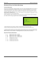
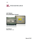
If such a plausibility conflict is detected, the ATS controller blocks all further automatic transfers and displays
the "Limit switch fail" message together with the actual and expected replies.
Figure 3-2: Limit switch monitoring - failure message
"Actual" indicates the reply messages, which are currently detected by the ATS limit switch.
"Expected" indicates the reply messages, which are expected to be detected by the ATS limit switch.
A continued automatic operation of the ATS controller is only possible after the "Actual" state matches the "Expected" state again. A "Reset" button will be displayed in the lower section of the screen if this is the case. This
button must be pressed by the operator to acknowledge the detection and the removal of the failure.
Signal and Command Abbreviations
•
•
•
•
•
•
•
•
S1
S2
S1O
S2O
C1
C2
C1O
C2O
Page 18/31
Signal: breaker in source 1 position
Signal: breaker in source 2 position
Signal: breaker in source 1 OPEN position
Signal: breaker in source 2 OPEN position
Command: close to source 1
Command: close to source 2
Command: open from source 1
Command: open from source 2
© Woodward
Manual 37387
DTSC-200 - ATS Controller
Truth Tables
The truth tables indicate all possible reply signal combination conditions and the respective reactions of the ATS
controller depending on the configuration of the parameters 3424 "Transfer switch type" and 3434 "Use limit sw.
OPEN replies". All conditions, which are OK according to the table (columns Actual and Expected) do not result
a "Limit switch fail" message.
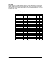
Table 3-1 is valid for the following settings:
• Parameter 3424 "Transfer switch type" is configured to "Standard"
• Parameter 3434 "Use limit sw. OPEN replies" is configured to "NO"
S1 preferred S1 source OK S2 source OK S1 closed signal S2 closed signal
0
0
0
0
0
0
0
0
0
1
0
0
0
1
0
0
0
0
1
1
0
0
1
0
0
0
0
1
0
1
0
0
1
1
0
0
0
1
1
1
0
1
0
0
0
0
1
0
0
1
0
1
0
1
0
0
1
0
1
1
0
1
1
0
0
0
1
1
0
1
0
1
1
1
0
0
1
1
1
1
1
0
0
0
0
1
0
0
0
1
1
0
0
1
0
1
0
0
1
1
1
0
1
0
0
1
0
1
0
1
1
0
1
1
0
1
0
1
1
1
1
1
0
0
0
1
1
0
0
1
1
1
0
1
0
1
1
0
1
1
1
1
1
0
0
1
1
1
0
1
1
1
1
1
0
1
1
1
1
1
Actual
----OK
OK
S1 S2
----OK
OK
S1 S2
----OK
OK
S1 S2
----OK
OK
S1 S2
----OK
OK
S1 S2
----OK
OK
S1 S2
----OK
OK
S1 S2
S1 S2
OK
OK
S1 S2
Expected
S2
OK
OK
S2
S2
OK
OK
S2
S1
OK
OK
S1
S2
OK
OK
S1
S1
OK
OK
S1
S2
OK
OK
S2
S1
OK
OK
S1
S1
OK
OK
S1
Table 3-1: Limit switch monitoring - truth table for "Standard" limit switch w/o "Open" replies
© Woodward
Page 19/31
Manual 37387
DTSC-200 - ATS Controller
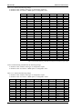
Table 3-2 is valid for the following settings:
• Parameter 3424 "Transfer switch type" is configured to "Delayed"
• Parameter 3434 "Use limit sw. OPEN replies" is configured to "NO"
S1 preferred
0
0
0
0
0
0
0
0
0
0
0
0
0
0
0
0
1
1
1
1
1
1
1
1
1
1
1
1
1
1
1
1
S1 source OK
0
0
0
0
0
0
0
0
1
1
1
1
1
1
1
1
0
0
0
0
0
0
0
0
1
1
1
1
1
1
1
1
S2 source OK
0
0
0
0
1
1
1
1
0
0
0
0
1
1
1
1
0
0
0
0
1
1
1
1
0
0
0
0
1
1
1
1
S1 closed signal
0
0
1
1
0
0
1
1
0
0
1
1
0
0
1
1
0
0
1
1
0
0
1
1
0
0
1
1
0
0
1
1
S2 closed signal
0
1
0
1
0
1
0
1
0
1
0
1
0
1
0
1
0
1
0
1
0
1
0
1
0
1
0
1
0
1
0
1
Actual
OK
OK
OK
S1 S2
OK
OK
OK
S1 S2
OK
OK
OK
S1 S2
OK
OK
OK
S1 S2
OK
OK
OK
S1 S2
OK
OK
OK
S1 S2
OK
OK
OK
S1 S2
OK
OK
OK
S1 S2
Expected
OK
OK
OK
S2
OK
OK
OK
S2
OK
OK
OK
S1
OK
OK
OK
S2
OK
OK
OK
S1
OK
OK
OK
S2
OK
OK
OK
S1
OK
OK
OK
S1
Table 3-2: Limit switch monitoring - truth table for "Delayed" limit switch w/o "Open" replies
Limit switch monitoring is disabled for the following settings:
• Parameter 3424 "Transfer switch type" is configured to "Open"
• Parameter 3434 "Use limit sw. OPEN replies" is configured to "NO"
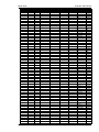
Table 3-3 is valid for the following settings:
• Parameter 3424 "Transfer switch type" is configured to "Open"
• Parameter 3434 "Use limit sw. OPEN replies" is configured to "YES"
S1 preferred
0
0
0
0
0
0
0
0
0
0
0
0
0
0
Page 20/31
S1 OK
0
0
0
0
0
0
0
0
0
0
0
0
0
0
S2 OK
0
0
0
0
0
0
0
0
0
0
0
0
0
0
S1 closed signal
0
0
0
0
0
0
0
0
1
1
1
1
1
1
S2 closed signal
0
0
0
0
1
1
1
1
0
0
0
0
1
1
S1 open signal
0
0
1
1
0
0
1
1
0
0
1
1
0
0
S2 open signal
0
1
0
1
0
1
0
1
0
1
0
1
0
1
Actual
----S2O
S1O
OK
S2
S2 S2O
OK
S2 S1O S2O
S1
OK
S1 S1O
S1 S1O S2O
S1 S2
S1 S2 S2O
Expected
S2 S1O
S2 S1O
S2 S1O
OK
S2 S1O
S2 S1O
OK
S2 S1O
S2 S1O
OK
S2 S1O
S2 S1O
S2 S1O
S2 S1O
© Woodward
Manual 37387
S1 preferred
0
0
0
0
0
0
0
0
0
0
0
0
0
0
0
0
0
0
0
0
0
0
0
0
0
0
0
0
0
0
0
0
0
0
0
0
0
0
0
0
0
0
0
0
0
0
0
0
0
0
1
1
1
1
1
1
1
1
1
1
1
1
1
1
1
1
© Woodward
DTSC-200 - ATS Controller
S1 OK
0
0
0
0
0
0
0
0
0
0
0
0
0
0
0
0
0
0
1
1
1
1
1
1
1
1
1
1
1
1
1
1
1
1
1
1
1
1
1
1
1
1
1
1
1
1
1
1
1
1
0
0
0
0
0
0
0
0
0
0
0
0
0
0
0
0
S2 OK
0
0
1
1
1
1
1
1
1
1
1
1
1
1
1
1
1
1
0
0
0
0
0
0
0
0
0
0
0
0
0
0
0
0
1
1
1
1
1
1
1
1
1
1
1
1
1
1
1
1
0
0
0
0
0
0
0
0
0
0
0
0
0
0
0
0
S1 closed signal
1
1
0
0
0
0
0
0
0
0
1
1
1
1
1
1
1
1
0
0
0
0
0
0
0
0
1
1
1
1
1
1
1
1
0
0
0
0
0
0
0
0
1
1
1
1
1
1
1
1
0
0
0
0
0
0
0
0
1
1
1
1
1
1
1
1
S2 closed signal
1
1
0
0
0
0
1
1
1
1
0
0
0
0
1
1
1
1
0
0
0
0
1
1
1
1
0
0
0
0
1
1
1
1
0
0
0
0
1
1
1
1
0
0
0
0
1
1
1
1
0
0
0
0
1
1
1
1
0
0
0
0
1
1
1
1
S1 open signal
1
1
0
0
1
1
0
0
1
1
0
0
1
1
0
0
1
1
0
0
1
1
0
0
1
1
0
0
1
1
0
0
1
1
0
0
1
1
0
0
1
1
0
0
1
1
0
0
1
1
0
0
1
1
0
0
1
1
0
0
1
1
0
0
1
1
S2 open signal
0
1
0
1
0
1
0
1
0
1
0
1
0
1
0
1
0
1
0
1
0
1
0
1
0
1
0
1
0
1
0
1
0
1
0
1
0
1
0
1
0
1
0
1
0
1
0
1
0
1
0
1
0
1
0
1
0
1
0
1
0
1
0
1
0
1
Actual
S1 S2 S1O
S1 S2 S1O S2O
----S2O
S1O
OK
S2
S2 S2O
OK
S2 S1O S2O
S1
OK
S1 S1O
S1 S1O S2O
S1 S2
S1 S2 S2O
S1 S2 S1O
S1 S2 S1O S2O
----S2O
S1O
OK
S2
S2 S2O
OK
S2 S1O S2O
S1
OK
S1 S1O
S1 S1O S2O
S1 S2
S1 S2 S2O
S1 S2 S1O
S1 S2 S1O S2O
----S2O
S1O
OK
S2
S2 S2O
OK
S2 S1O S2O
S1
OK
S1 S1O
S1 S1O S2O
S1 S2
S1 S2 S2O
S1 S2 S1O
S1 S2 S1O S2O
----S2O
S1O
OK
S2
S2 S2O
OK
S2 S1O S2O
S1
OK
S1 S1O
S1 S1O S2O
S1 S2
S1 S2 S2O
S1 S2 S1O
S1 S2 S1O S2O
Expected
S2 S1O
S2 S1O
S2 S1O
S2 S1O
S2 S1O
OK
S2 S1O
S2 S1O
OK
S2 S1O
S2 S1O
OK
S2 S1O
S2 S1O
S2 S1O
S2 S1O
S2 S1O
S2 S1O
S1 S2O
S1 S2O
S1 S2O
OK
S1 S2O
S1 S2O
OK
S1 S2O
S1 S2O
OK
S1 S2O
S1 S2O
S1 S2O
S1 S2O
S1 S2O
S1 S2O
S2 S1O
S2 S1O
S2 S1O
OK
S2 S1O
S2 S1O
OK
S2 S1O
S2 S1O
OK
S2 S1O
S2 S1O
S2 S1O
S2 S1O
S2 S1O
S2 S1O
S1 S2O
S1 S2O
S1 S2O
OK
S1 S2O
S1 S2O
OK
S1 S2O
S1 S2O
OK
S1 S2O
S1 S2O
S1 S2O
S1 S2O
S1 S2O
S1 S2O
Page 21/31
Manual 37387
S1 preferred
1
1
1
1
1
1
1
1
1
1
1
1
1
1
1
1
1
1
1
1
1
1
1
1
1
1
1
1
1
1
1
1
1
1
1
1
1
1
1
1
1
1
1
1
1
1
1
1
DTSC-200 - ATS Controller
S1 OK
0
0
0
0
0
0
0
0
0
0
0
0
0
0
0
0
1
1
1
1
1
1
1
1
1
1
1
1
1
1
1
1
1
1
1
1
1
1
1
1
1
1
1
1
1
1
1
1
S2 OK
1
1
1
1
1
1
1
1
1
1
1
1
1
1
1
1
0
0
0
0
0
0
0
0
0
0
0
0
0
0
0
0
1
1
1
1
1
1
1
1
1
1
1
1
1
1
1
1
S1 closed signal
0
0
0
0
0
0
0
0
1
1
1
1
1
1
1
1
0
0
0
0
0
0
0
0
1
1
1
1
1
1
1
1
0
0
0
0
0
0
0
0
1
1
1
1
1
1
1
1
S2 closed signal
0
0
0
0
1
1
1
1
0
0
0
0
1
1
1
1
0
0
0
0
1
1
1
1
0
0
0
0
1
1
1
1
0
0
0
0
1
1
1
1
0
0
0
0
1
1
1
1
S1 open signal
0
0
1
1
0
0
1
1
0
0
1
1
0
0
1
1
0
0
1
1
0
0
1
1
0
0
1
1
0
0
1
1
0
0
1
1
0
0
1
1
0
0
1
1
0
0
1
1
S2 open signal
0
1
0
1
0
1
0
1
0
1
0
1
0
1
0
1
0
1
0
1
0
1
0
1
0
1
0
1
0
1
0
1
0
1
0
1
0
1
0
1
0
1
0
1
0
1
0
1
Actual
----S2O
S1O
OK
S2
S2 S2O
OK
S2 S1O S2O
S1
OK
S1 S1O
S1 S1O S2O
S1 S2
S1 S2 S2O
S1 S2 S1O
S1 S2 S1O S2O
----S2O
S1O
OK
S2
S2 S2O
OK
S2 S1O S2O
S1
OK
S1 S1O
S1 S1O S2O
S1 S2
S1 S2 S2O
S1 S2 S1O
S1 S2 S1O S2O
----S2O
S1O
OK
S2
S2 S2O
OK
S2 S1O S2O
S1
OK
S1 S1O
S1 S1O S2O
S1 S2
S1 S2 S2O
S1 S2 S1O
S1 S2 S1O S2O
Expected
S2 S1O
S2 S1O
S2 S1O
OK
S2 S1O
S2 S1O
OK
S2 S1O
S2 S1O
OK
S2 S1O
S2 S1O
S2 S1O
S2 S1O
S2 S1O
S2 S1O
S1 S2O
S1 S2O
S1 S2O
OK
S1 S2O
S1 S2O
OK
S1 S2O
S1 S2O
OK
S1 S2O
S1 S2O
S1 S2O
S1 S2O
S1 S2O
S1 S2O
S1 S2O
S1 S2O
S1 S2O
OK
S1 S2O
S1 S2O
OK
S1 S2O
S1 S2O
OK
S1 S2O
S1 S2O
S1 S2O
S1 S2O
S1 S2O
S1 S2O
Table 3-3: Limit switch monitoring - truth table for "Open" limit switch with "Open" replies
Page 22/31
© Woodward
Manual 37387
DTSC-200 - ATS Controller
Chapter 4.
Configuration
This chapter provides information "how to configure the unit via the LC display" as well as the description of all
parameters that may be changed without a password. If you have the correct passwords to access all code levels
in order configure the unit, refer to manual 37386 for a description of all parameters, their setting range, and their
influence to the operation of the unit.
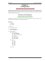
Structure of the Parameters
≡≡≡≡≡≡≡≡≡≡≡≡≡≡≡≡≡≡≡≡≡≡≡≡≡
The parameters, which may be accessed in code level 0 (no access restrictions) are structured as follows (refer to
the Parameters section on page 25 for a more detailed description):
Main Menu
► Language
► English
► German
► Password
► Change display contrast
► Configure monitoring
► Time until horn reset
► System parameter
► Password system
► Code level display
► Code level CAN port
► Code level serial port / DPC
► Password
► Password CAN
► Password DPC
► Factory settings
► Set clock
► Hour
► Minute
► Second
► Day
► Month
► Year
► Version
© Woodward
Page 23/31
Manual 37387
DTSC-200 - ATS Controller
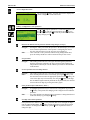
Access configuration menus
By pressing the softkey, the main menu will be displayed to
permit configuration of the control unit.
Softkeys "Configuration - select parameter"
Navigation through the parameters is carried out using the softkeys and . To edit the selected parameter press . To save
the edited parameter press . To exit the parameter without saving any changes press .
Return to the Main Screen/exit parameter without saving changes ("Escape")
Navigate ...... Pressing the softkey will return the operator to the main display screen that
shows monitored parameters. If the operator is configuring the control
unit, this will return the user to the previous screen displayed.
Edit .............. I If it is desired to exit a parameter without saving changes made there,
press the softkey and the user will be returned to the previous screen.
Next parameter
Navigate ...... This softkey permits the user to navigate down through the parameters.
Only the parameters assigned by the active password will be displayed.
The parameters that may be viewed without a password are described later
in this manual.
Previous parameter/increase/change function
Navigate ...... This softkey permits the user to navigate upwards through the parameters.
Edit .............. If the desired parameter has been selected by pressing the softkey, and
the cursor has been moved to the appropriate position via the softkey, the
value of the digit may be increased by one using the softkey. If the digit
has reached the highest numeral permitted for the placeholder, the unit will
return to the lowest digit by pressing the softkey again.
Select parameter/input confirmation ("Enter")
Navigate ...... A highlighted parameter may be enter into for configuration by pressing
the softkey. This permits the changing of the configured value within the
parameter.
Edit .............. Any value that has been changed within a parameter is changed and stored
in the unit memory by pressing the softkey.
Next digit of the selected parameter
If the parameter has a numeric value (i.e. the password) that is to be changed, the digits
must be changed individually. The softkey permits navigation to each cursor position
of the number to be changed. See the softkey symbols for an explanation of how to
change the digit.
Page 24/31
© Woodward
Manual 37387
DTSC-200 - ATS Controller
Parameters
≡≡≡≡≡≡≡≡≡≡≡≡≡≡≡≡≡≡≡≡≡≡≡≡≡
NOTE
A description of all parameters, which may be edited/configured via the display, are described in manual 37386.
DE EN
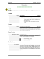
Language
Language
Language
Change language
{Language}
{Language}..The selection of a language will affect the following text
in the control unit:
• Text in the operating field which are not defined by an
input (i.e. discrete inputs may be a user-defined text)
• The alarm list text
• All parameters which may be changed via the unit
panel
GR EN
Password
Password
Passwort
Password for access via the unit panel
0000 to 9999
A password must be entered to permit configuration of the unit via the
unit panel. If a password is not entered only the displayed parameters
may be edited. All other parameters and a description of their functions
may be found in the manual 37386.
GR EN
Display Contrast
Change display contrast
Displaykontrast ändern
Change display contrast
+/-
In parameter "Change display contrast" the display contrast may be increased or decrease using these softkey characters.
....................Increase the display contrast.
....................Decrease the display contrast.
....................Performs a lamp test.
GR EN
Deactivate Horn
Time until horn reset
Zeit Hupenreset
Self acknowledgement of the horn signal
0 to 1.000 s
A horn signal is issued and the alarm LED flashes when a fault condition occurs. This signal will be disabled when the configured time expires. This is the maximum time, for which a horn signal is active (it
will also be deactivated if it is acknowledged before). If this parameter
is configured to 0, the horn will remain active until it will be aconowledged.
© Woodward
Page 25/31
Manual 37387
DTSC-200 - ATS Controller
GR EN
Code Levels
Code level display
Codeebene Display
Code level via display
Info
GR EN
This value displays the code level that is currently active for access via
the front panel.
Code level CAN port
Codeebene CAN Schnittstel.
Password CAN-Bus
Info
GR EN
This value displays the code level that is currently active for access via
the CAN bus.
Code level serial port / DPC
Codebene serielle Schnittstel
Code level RS-232 (DPC interface)
Info
This value displays the code level that is currently active for access via
the serial RS-232 (DPC) interface.
GR EN
Password
Password
Passwort
Password for access via the unit panel
0000 to 9999
GR EN
A password must be entered to permit configuration of the unit via the
unit panel. If a password is not entered only the displayed parameters
may be edited. All other parameters and a description of their functions
may be found in the manual 37386.
Password CAN
Passwort CAN
Password for access via CAN
0000 to 9999
GR EN
A password must be entered to permit configuration of the unit via the
CAN bus. If a password is not entered only the displayed parameters
may be edited. All other parameters and a description of their functions
may be found in the manual 37386.
Password DPC
Passwort RS232
Password for access via DPC
0000 to 9999
A password must be entered to permit configuration of the unit via the
DPC interface. If a password is not entered only the displayed parameters may be edited. All other parameters and a description of their functions may be found in the manual 37386.
GR EN
Factory (Default) Values
Factory settings
Werkseinstellung
Factory setting
YES/NO
GR EN
The factory settings (default values) may be loaded. Select YES to enable the following screen to be displayed. It is possible to load the factory settings (default values) for all displayed parameters.
Set default values
Standardwerte
Set default values
YES/NO
Entering YES overwrites the current configured values with the default
values. Only those parameters will be reset, which are permitted to
change in the selected code level.
Page 26/31
© Woodward
Manual 37387
DTSC-200 - ATS Controller
GR EN
Real-Time Clock - Time
Hour
Stunden
Adjust clock time: hour
0 to 23
GR EN
The hour of the current time is set here. Example:
0....................0th hour of the day.
23..................23rd hour of the day.
Minute
Minuten
Adjust clock time: minute
0 to 59
GR EN
The minute of the current time is set here. Example:
0....................0th minute of the hour.
59..................59th minute of the hour.
Second
Sekunden
Adjust clock time: second
0 to 59
The second of the current time is set here. Example:
0....................0th second of the minute.
59..................59th second of the minute.
GR EN
Real-Time Clock - Date
Day
Tag
Adjust date: day
1 to 31
GR EN
The day of the current date is set here. Example:
1....................1st day of the month.
31..................31st day of the month.
Month
Monat
Adjust date: month
1 to 12
GR EN
The month of the current date is set here. Example:
1....................1st month of the year.
12..................12th month of the year.
Year
Jahr
Adjust date: year
0 to 99
The year of the current date is set here. Example:
0....................Year 2000.
99..................Year 2099.
GR EN
Version
Version
Version
Displays system information
Info
System information, like serial number of the unit and software version
is displayed.
© Woodward
Page 27/31
Manual 37387
DTSC-200 - ATS Controller
Appendix A.
Messages
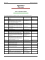
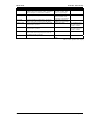
Timer / Operation States
≡≡≡≡≡≡≡≡≡≡≡≡≡≡≡≡≡≡≡≡≡≡≡≡≡
The following table indicates the display messages of the various timers and operations states:
Display text
S1 Start delay
S2 Start delay
S1 Stable timer
S2 Stable timer
S1 Cooldown
S2 Cooldown
Load on S1
Starting S2
Load on S2
Load test
No load test
Elevator signal
Starting S1
Wait S1 to open
Wait S2 to open
Wait S1 to close
Wait S2 to close
Rem. peak shave
Description
Source 2 has failed, and now the S1 start delay timer is
running.
Source 1 has failed, and now the S2 start delay timer is
running.
The transfer from Source 2 to Source 1 is delayed, to
permit stabilization of Source 1 before a re-transfer is
made. If Source2 fails during timing, a re-transfer to
Source 1 will be performed immediately.
The transfer from Source 1 to Source 2 is delayed, to
permit stabilization of Source 2 before a transfer is made.
Engine runs unloaded, after a retransfer to Source 2 has
been made. This is to ensure that engine 1 has enough
time to cool down.
Engine runs unloaded, after a retransfer to Source 1 has
been made. This is to ensure that engine 2 has enough
time to cool down.
Source 1 is connected to the load.
Engine 2 is being started.
Source 1 has failed, and Source 2 is powering the load.
The ATS system is in "Load test" mode . A Source 1 failure is simulated ( The ATS controllers behaves in the
same way like an Source 1 failure has been occurred ).
The ATS system is in "No load Test" mode. This means,
that the engine runs unloaded, and no transfers will take
place. This test mode is used to check whether the engine
is started or not.
The Elevator pre-signal timer is running. This message
only occurs, if the "Elevator pre-signal" feature is activated and BOTH sources are available. If only one source
is available (like in an emergency case) the elevator presignal timer will automatically be bypassed.
Engine 1 is being started.
A command is issued by the ATS Controller to open the
ATS switch from Source 1 position
A command is issued by the ATS Controller to open the
ATS switch from Source 2 position
A command is issued by the ATS Controller to close the
ATS switch into Source 1 position
A command is issued by the ATS Controller to close the
ATS switch into Source 2 position
"Remote peak shave" mode is active
Corresponding timer parameter Note
"S1 start delay time"
Gen-Gen mode only
"S2 start delay time"
Util-Gen and Gen-Gen
mode only
"S1 Source Stable time"
"S2 Source Stable time"
"S1 cooldown time"
Only for Gen-Gen applications
"S2 cooldown time"
Util-Gen and Gen-Gen
mode only
"S2 Start fail delay time"
Load test activation either via
"Load test" Softkey or via
"Load Test - Logicsmanager"
No load test activation either
via "Engine test" Softkey or
via "No Load Test Logicsmanager"
Elevator pre-signal duration
"S1 Start fail delay time"
Only for Gen-Gen applications
"Limit switch reply timeout"
"Limit switch reply timeout"
"Limit switch reply timeout"
"Limit switch reply timeout"
Remote peak shave activation
via "Remote peak shave Logicsmanager"
Motor Load Disc. The Motor Load Disconnect timer is running. This mes"Disconnect time S1"
sage only occurs, if the "Motor load disconnect" feature is and/or
"Disconnect time S2"
activated.
Inhib. XFR to S1 A transfer to Source 1 is inhibited although Source 1 is
"Inhibit transfer to Source 1"
available. In the case of an Source 2 failure, a transfer to
activation via "Inhib. XFR to
Source 1 takes place, even the transfer is inhibited
Source 1 - Logicsmanager"
Page 28/31
© Woodward
Manual 37387
Display text
Inhib. XFR to S2
Load Shed active
Pwr. rate. prov.
ATS inhibit
Neutral S1 S2
DTSC-200 - ATS Controller
Description
A transfer to Source 2 is inhibited although Source 2 is
available. In the case of an Source 1 failure, a transfer to
Source 2 takes place, even the transfer is inhibited.
Load shed is active
"Interruptible power rate provisions" mode is active
The ATS Controller is in "Inhibit mode". No transfers
take place if the ATS controller is set into this mode.
The ATS controller delays the transfer from NEUTRAL
position to Source 2 position.
Neutral S1S2
The ATS controller delays the transfer from NEUTRAL
position to Source 1 position.
In-Phase Check
The ATS controller performs an In-Phase check before a
transfer is made. This message only occurs, if the "Inphase monitor" feature is activated.
The ATS controller delays the next transfer attempt.
Transfer pause
Corresponding timer parameter Note
"Inhibit transfer to Source 2"
activation via "Inhib. XFR to
Source 2 - Logicsmanager"
"Interruptible power rate provisions" activation via "Int.
Power Rates - Logicsmanager"
"ATS inhibit" activation via
"Inhibit ATS - Logicsmanager"
Neutral time S1 S2
Only available if Transition mode "Delayed" or
"Closed" is selected.
Neutral time S2 S1
Only available if Transition mode "Delayed" or
"Closed" is selected.
"Wait time until next XFR attempt"
Table 4-1: Timer / operation states - display
© Woodward
Page 29/31
Manual 37387
DTSC-200 - ATS Controller
Alarm Messages
≡≡≡≡≡≡≡≡≡≡≡≡≡≡≡≡≡≡≡≡≡≡≡≡≡
Message in LeoPC1
Meaning
Message in the display
Batt.overvolt. Lev.1
Battery overvoltage, limit value 1
Batt.overvolt.1 The battery voltage has exceeded the limit value 1 for battery overvoltage for at least the configured
time and did not fall below the value of the hysteresis. Additionally, the alarm has not been acknowledged (unless the "Self acknowledgement" is configured YES).
Batt.overvolt. Lev.2
Battery overvoltage, limit value 2
Batt.overvolt.2 The battery voltage has exceeded the limit value 2 for battery overvoltage for at least the configured
time and did not fall below the value of the hysteresis. Additionally, the alarm has not been acknowledged (unless the "Self acknowledgement" is configured YES).
Batt.undervolt. Lev.1
Battery undervoltage, limit value 1
Batt.undervolt.1 The battery voltage has fallen below the limit value 1 for battery undervoltage for at least the configured time and has not exceeded the value of the hysteresis. Additionally, the alarm has not been
acknowledged (unless the "Self acknowledgement" is configured YES).
Batt.undervolt. Lev.2
Battery undervoltage, limit value 2
Batt.undervolt.2 The battery voltage has fallen below the limit value 2 for battery undervoltage for at least the configured time and has not exceeded the value of the hysteresis. Additionally, the alarm has not been
acknowledged (unless the "Self acknowledgement" is configured YES).
CAN Open Fault
Interface alarm CAN Open
CAN Open Fault The communication with external expansion boards via the CAN Open interface has been interrupted and no data can be transmitted or received over the bus. Additionally, the alarm has not been
acknowledged (unless the "Self acknowledgement" is configured YES).
Fail to close S1
Switch failed to close to source 1
The ATS controller has issued a "close" command to close the transfer switch to source 1 position,
but did not receive any feedback from the limit switch reply "SN" at DI 1 (terminal 51) within the
configured time.
Fail to close S2
Switch failed to close to source 2
The ATS controller has issued a "close" command to close the transfer switch to source 2 position,
but did not receive any feedback from the limit switch reply "SE" at DI 2 (terminal 52) within the
configured time.
Fail to open S1
Switch failed to open from source 1
The ATS controller has issued an "open" command to open the transfer switch from source 1 position, but did not receive any feedback from the limit switch reply "SNO" at DI 5 (terminal 55)
within the configured time.
Fail to open S2
Switch failed to open from source 2
The ATS controller has issued an "open" command to open the transfer switch from source 2 position, but did not receive any feedback from the limit switch reply "SNE" at DI 4 (terminal 54)
within the configured time.
Overcurrent Lev.1
Overcurrent, limit value 1
The generator current has exceeded the limit value 1 for the generator overcurrent for at least the
configured time and did not fall below the value of the hysteresis. Additionally, the alarm has not
been acknowledged (unless the "Self acknowledgement" is configured YES).
Overcurrent Lev.2
Overcurrent, limit value 2
The generator current has exceeded the limit value 2 for the generator overcurrent for at least the
configured time and did not fall below the value of the hysteresis. Additionally, the alarm has not
been acknowledged (unless the "Self acknowledgement" is configured YES).
Overcurrent Lev.3
Overcurrent, limit value 3
The generator current has exceeded the limit value 3 for the generator overcurrent for at least the
configured time and did not fall below the value of the hysteresis. Additionally, the alarm has not
been acknowledged (unless the "Self acknowledgement" is configured YES).
Gen.overload Lev.1
Overload, limit value 1
The generator power has exceeded the limit value 1 for generator overload for at least the configured time and did not fall below the value of the hysteresis. Additionally, the alarm has not been
acknowledged (unless the "Self acknowledgement" is configured YES).
Gen.overload Lev.2
Overload, limit value 1
The generator power has exceeded the limit value 1 for generator overload for at least the configured time and did not fall below the value of the hysteresis. Additionally, the alarm has not been
acknowledged (unless the "Self acknowledgement" is configured YES).
Page 30/31
© Woodward
Manual 37387
DTSC-200 - ATS Controller
Message in LeoPC1
Meaning
Message in the display
In-phase timeout
Inphase timer has expired
If inphase monitoring is enabled and the unit was not able to detect a synchronicity between
source 1 and source 2 within the configured time, this message will be displayed.
Mechanical fail
Mechanical failure occurred
The limit switch reply evaluation system has recognized an irregular state of the limit switches
from the transfer switch. The screen gives detailed information about the ACTUAL reply signals, and the EXPECTED reply signals. Once the Actual reply signals meet the same state than
the expected ones, the mechanical failure will acknowledge itself and records an entry in the
event history.
Overlap timeout
Switch was unable to open from overlap position
The limit switch reply evaluation system has recognized an irregular state of the limit switches
from the transfer switch. It was not possible to open the transfer switch from both sources.
S1 phase rot.mis.
Source 1 phase rotation miswired
If source 1 phase rotation monitoring is enabled and a miswired phase rotation has been detected, this message will be displayed.
S2 phase rot.mis.
Source 2 phase rotation miswired
If source 2 phase rotation monitoring is enabled and a miswired phase rotation has been detected, this message will be displayed.
Start fail S1
Source 1 could not be started
Genset 1 could not be started. This is only valid if the application mode is configured to "GenGen".
Start fail S2
Source 2 could not be started
Genset 2 could not be started.
Un. stop S1
Genset 1 has stopped unintentionally
An unintended stop of genset 1 has occurred (possibly due to a fuel shortage or a general problem with the engine). This is only valid if the application mode is configured to "Gen-Gen".
Un. stop S2
Genset 2 has stopped unintentionally
An unintended stop of genset 2 has occurred (possibly due to a fuel shortage or a general problem with the engine).
© Woodward
Page 31/31
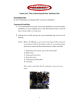
We appreciate your comments about the content of our publications.
Please send comments to: [email protected]
Please include the manual number from the front cover of this publication.
Woodward GmbH
Handwerkstrasse 29 - 70565 Stuttgart - Germany
Phone +49 (0) 711 789 54-0 • Fax +49 (0) 711 789 54-100
[email protected]
Homepage
http://www.woodward.com/power
Woodward has company-owned plants, subsidiaries, and branches, as well as authorized
distributors and other authorized service and sales facilities throughout the world.
Complete address/phone/fax/e-mail information
for all locations is available on our website (www.woodward.com).
2007/12/Stuttgart