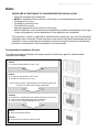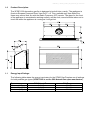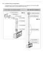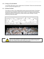
1
630140_1 XFIRE_1200_GB_Manual_R‐emotion X-FIRE 1200
®
Designer Balanced Flue Fires
INSTALLATION & USERS INSTRUCTIONS
PRODUCT CODES
XT-LIM X-FIRE 1200 Limestone
XT-GRA X-FIRE 1200 Granite
XT-TRA X-FIRE 1200 Travertine
LEAVE WITH THE USER
Acquisitions of London
24 Holmes Road
London NW5 3AB
England
Tel: 0044 (0)207 482 2949
Email: [email protected]
630140_1 XFIRE_1200_GB_Manual_R‐emotion INTELLECTUAL PROPERTY
Acquisitions XFIRES is a Registered Trade Mark
Components of this product are protected under GB Patent no: GB2429186
Similar applications are pending in Europe, USA, Canada, China, Hong Kong,
Australia and New Zealand.
Important:
The appliance shall be installed in accordance with;
• This installation instruction booklet
• Local gas fitting regulations and The Rules in Force
• BS 5440-1
• BS 5871-1:2005 & BS 6891
• Any other relevant statutory regulations.
• Must be installed by a Registered Installer
• Converting this appliance for use with G31 Propane must be done by a Registered
Installer
• This appliance is for use on Natural Gas (G20) at a supply pressure of 20mbar or
Propane(G31) at a supply pressure of 37mbar.
• In IE, consult document I.S. 813:1996 Domestic Gas Installation.
DISTRIBUTED BY
Acquisitions of London
24-26 Holmes Road
London NW5 3AB
Tel: 24 hours 0044 (0)207 482 2949
Email: [email protected]
630140_1 XFIRE_1200_GB_Manual_R‐emotion Note:
THERE ARE A FEW THINGS TO CONSIDER BEFORE INSTALLATION
•
•
•
•
•
•
•
Cavity Dimensions and Clearances
MUST be installed 100mm minimum off the floor or nearest horizontal surface.
Coupling of flue to fire
Coupling of gas lines to fire
Fixing the fire to cavity
Gas pipe placement to the front left of the cavity.
Before installation, ensure that the local distribution conditions (identification of the type
of gas and pressure) and the adjustment of the appliance are compatible.
The sequence in which it is desired to undertake these tasks may vary upon the individual
installation that is required. Please read these instructions fully before proceeding with the
installation. Leave unpacking and installation of the stone frame (facia) until the fireplace
has been commissioned, to avoid damage to the facia panels.
Recommended Installation Process:
The following diagram illustrates the steps required to install your gas fire, and the trades
required at each stage.
Builder 1. Construct Frame (Section 1.0 to 6.0) Gasfitter 2. Install Gas Pipe (Section 7.0 to 8.0) 3. Install Fire (Section 9.0 to 11.0) Ensure that you leave a gap between the studwork and the fire chassis to accept the wall lining if applicable. Gasfitter 4. Install Flue + Flue Restrictor if required (Section 12.0 to 13.0) 5. Test fire and verify flame pattern is acceptable 6. Cover‐up fire using packaging (Section 17.0) Builder 7. Clad / line chimney breast Gasfitter 8. Commission the Gas Fire (Section 18.0) 630140_1 XFIRE_1200_GB_Manual_R‐emotion Contents:
1.0
2.0
3.0
4.0
5.0
6.0
7.0
8.0
9.0
10.0
11.0
12.0
13.0
14.0
15.0
16.0
17.0
18.0
19.0
20.0
21.0
22.0
23.0
Product Description
Creating the Cavity
Hearth and Floor Clearances
Wall Linings
Vertical Clearances
Corner Installations
Laying Gas Pipe
Connecting Gas Pipe
Power Supply
Fixing Fire to Wall
Removing the Firebox Glass
Installing the Flue system
Fitting the Flue Restrictor
Converting to G31 Propane Gas
Placing the Fuel Bed
Checking Operating Pressure
Covering up the Fire
Commissioning the Fire (Including fitting the facia)
Operating Instructions
Sounds and Smells
Annual Service Check
Installation Check List
Warranty Terms and Conditions
WARNING:
Failure to follow these instructions could cause a malfunction of the fire, which,
could result in death, serious bodily injury, and/or property damage. Failure to follow
these instructions may also void insurance cover and/or product warranty.
Installation:
Installation must be carried out by a registered installer who, on completion of the
installation, must issue a certificate of compliance, in accordance with national and/or local
codes. To find a registered installer in the UK go to the Gas Safe website –
www.gassaferegister.co.uk In the rebulic of Ireland go to www.rgii.ie
Warranty Repair and Annual Servicing:
Warranty repair work must be carried out by a registered gas installer. It is recommended
that registered gas installers are also used to carry out annual servicing requirements
(particularly during the warranty period). For contact details of UK registered gas installers
in your area, go to the Gas Safe website at www.gassaferegister.co.uk and in the Republic
of Ireland go to www.rgii.ie
This product must be installed according to these instructions and in compliance with all
relevant building, gas fitting and other statutory regulations (eg. BS 5871-1:2005,
BS5440-1 and BS 6891). Any shortcomings in the appliance and flue installation will be
the responsibility of the installer, and Escea will not be accountable for any such failings or
their consequences.
630140_1 XFIRE_1200_GB_Manual_R‐emotion 1.0
Product Description:
The XFIRE 1200 decorative gas fire is designed to be built into a cavity. The appliance is
flued via Simpson Duravent Direct Vent Pro 5” x 8” Flue, available only from SpecFlue.
Users may control their fire with the Radio Frequency (RF) remote. The glass on the front
of the appliance is considered a working surface, and as such, care should be taken not to
touch this while the appliance is running as it will get hot.
1.1
Energy Input Ratings:
The following table states the energy input rates for the ST900 Gas Fireplace on all settings
for both possible gas types (XFIRE 1200 is set for G20 Natural Gas upon manufacture).
Gas
Minimum (kW)
Intermediate (kW)
Maximum (kW)
G20 Natural Gas
3.9 kW
4.6 kW
4.8 KW
G31 Propane
5.2 kW
5.4 kW
5.5 kW
630140_1 XFIRE_1200_GB_Manual_R‐emotion 2.0
Creating the Cavity:
The dimensioned drawing below shows the size of opening that must be created to fit the
XFIRE 1200. The wall directly above the fire should be finished / clad / lined after the fire
has been installed, unless there is an access hatch or the chase is open to the ceiling
cavity, which allows the flue to be installed after the wall has been lined.
Note: It is not necessary to line or vent the cavity, and it may be constructed with timber.
The wall and framework in front of the flue must not exceed 100mm in thickness, this includes plaster board or any wall linings. This is to ensure there is at least 25mm gap between all fluing components and any combustible material.
100mm MAX
Flue Diam.
203mm
3.0
Hearth and Floor Clearances:
There should be at least 100mm between the bottom of the XFIRE 1200 and any horizontal
surface below, for example hearths and floors.
3.1
Wall and Cabinet Clearances:
There must be a minimum of 100mm from the sides of the facia to any protruding side
walls or cabinetry.
4.0
Wall Linings:
The wall board that lines the outside of this opening can be normal dry wall
(Plaster Board) and does not need to be non-combustible providing that it does not come
any closer to the fire than the dimensions shown in section 2.0. Note: The temperature of
the wall lining directly above the heater does get warm and hence may discolour paint
finishes that are susceptible to temperature damage or distort vinyl wall coverings.
5.0
Television Positioning Considerations:
It is becoming common practice for consumers to mount flat screen TV’s above their gas
fireplace.
Most TV manufacturers have specified in their instructions that the TV should not be
installed on, near or above a heat source. For this reason TV location decisions rest solely
with the householder and Escea will not be held liable for any adverse affects on a TV
located near to an Escea fireplace that may be caused by heat.
The drawings overleaf are suggestions that may be used as a GUIDE for those consumers
who do decide to locate their TV above an XFIRE 1200 gas fire. These drawings show
ways to reduce the amount of warm air rising off the fireplace and onto the TV
630140_1 XFIRE_1200_GB_Manual_R‐emotion Flush TV with
small mantle
Recessed TV
Mantle above fire
Protruding fire
50 min
50 min
100 min
50 min
50 min
50 min
50 min
50 min
100 min
Mantle
Mantle
500 min
500 min
500 min
500 min
The material that the wall and mantle are made from will also affect the operating
temperature of the TV so it is the customers responsibility to satisfy themselves that their
TV mounting and mantle design will not exceed the listed maximum operating temperature
of their electronic goods.
5.1
Combustible Mantle Clearances:
The diagram to the right shows the minimum and
maximum allowable size for mantles or protruding
surfaces mounted above the XFIRE 1200.
of
Note: Acquisitions does not recommend placement
items on the mantles shown in the diagram to the
right. This is because of the potential for items
placed on or above the mantle to be affected by the
heat rising from the appliance.
630140_1 XFIRE_1200_GB_Manual_R‐emotion 5.2
Non-Combustible Mantle Clearances:
If the entire installation (mantle, wall and cavity) is
constructed from non-combustible materials, the clearances
to mantles may be as shown in the shaded area.
6.0
Corner Installations:
If a cavity is to be created in a corner,
the following drawing gives the minimum
sizes.
7.0
Laying Gas Pipe:
Gas pipe should be sized as per the requirements of BS 6896. The pipe sizing must be
sufficient to deliver the following volume of gas to the heater with all other gas appliances in
the home running at the same time on Natural Gas (G20).
XFIRE 1200 = 4.8kW
XFIRE 1200 = 0.45 m3/h
630140_1 XFIRE_1200_GB_Manual_R‐emotion 8.0
Connecting the Gas Pipe to the Fireplace:
Before the gas pipe can be connected to the fireplace, the Inlet Connection fitting and the
Inlet Test Point fitting must first be fitted to the appliance pressure regulator.
8.1
The fittings supplied with the fire need to be fitted to the pressure governor. A suitable joint
sealant and/or thread tape needs to be used on these unions.
The diagram below shows how to correctly assemble these two fittings to the pressure
regulator inlet side connection.
8.2
Soft copper should be run directly to fire and connected onto the regulator by means of an
8mm diameter compression fitting. An accessible inline isolation or service valve should
also be fitted. The regulator that is supplied with the fire MUST NOT BE REMOVED.
Removal of the regulator, or replacing it with one not intended for use with an XFIRE 1200,
will void the limited appliance warranty and could result in an unsafe installation.
9.0
Battery-Pack Power Supply:
The XFIRE 1200 runs on a battery pack. This battery pack uses 3x D cell batteries. To
ensure that only fresh batteries are used, batteries are not supplied with the fireplace.
These will be supplied by the installer.
To access the battery pack, remove the facia (described in section 17.0) and the battery
pack will be on the lower right hand side.
The Battery Pack is secured in place with Velcro pads and may be removed by firmly
pulling upwards.
630140_1 XFIRE_1200_GB_Manual_R‐emotion 10.0
Fixing the Fire to the base and wall:
It is a requirement that this fire be securely
fastened to the wall and base. Once the fire has
been pushed back into the correct position, use
wood screws (or other suitable fasteners) to fix
the fire to the cavity through each of the four
holes in the corners, as shown in the diagram to
the right. Note: It may be necessary to use
washers on the fasteners to securely fasten the
fire to the wall.
When fixing the fireplace in position ensure that
you leave a gap between the fireplace flange
and the framing timber for the wall lining, which
will be added at a later stage.
11.0
Removing the Firebox Glass:
Pull the four hooks shown below towards you and then away from the glass to release the
glass frame underneath the hook.
Do not operate the appliance if the glass has been broken, damaged, or the glass is
not properly positioned/hooked onto the appliance.
630140_1 XFIRE_1200_GB_Manual_R‐emotion 12.0
Installing the Flue System:
Ensure all flue components are Simpson Duravent Direct Vent Pro 5” x 8,” no other flue
types may be used. This flue is available on 24 hour delivery only from SpecFlue UK
FreeFone 0800 9020220 International +44 1787 880333
Note: Consult section 12.13 of this installation manual to ensure correct length of
flue is calculated.
There are two basic types of Balanced Flue System installations:
• Horizontal Termination
• Vertical Termination
Use the diagrams in sections 12.5, 12.6 & 12.7 to check if your proposed flue system is
acceptable. Section 12.9 will also need to be used to determine whether the flue terminal
location meets the requirements of BS 5440-1. Then use Appendix A to work out the
quantities of the flue components that are required.
12.1
Any offsets in your flue configuration should be 45° where possible.
12.2
If your flue configuration has a horizontal run, there must be a minimum 1° inclination
(20mm vertical rise per 1m horizontal run) leading upwards towards the termination.
Do not install the flue with horizontal sections sloping down towards the termination.
This could cause the fire to operate incorrectly and possibly create an unsafe
50mm
50mm
condition.
12.3
The flue must maintain the following
clearances to combustible materials;
25mm from all sides and bottom of
the flue, and 50mm from the top of
the flue.
25mm
25mm
25mm
Flue
25mm
25mm
25mm
115mm (REF)
12.4
30 Elbow
If your flue configuration falls on or near a restriction zone boundary line in diagrams 12.5,
12.6 & 12.7, it may require the restriction value from either side of the boundary line to
achieve the correct flame aesthetic, this may vary from installation to installation.
630140_1 XFIRE_1200_GB_Manual_R‐emotion 12.5
Vertical Only Flue Diagram:
Use this diagram to determine what percentage of flue restriction is required to ensure safe and correct operation of the XFIRE1200 balanced flue decorative gas fireplace. 630140_1 XFIRE_1200_GB_Manual_R‐emotion 12.6
Horizontally Terminating Flue Diagram:
Use this diagram to determine what percentage of flue restriction is required to ensure safe and correct operation of the XFIRE1200 balanced flue decorative gas fireplace. 630140_1 XFIRE_1200_GB_Manual_R‐emotion 12.7
Vertically Terminating flue with a Horizontal Offset:
Use this diagram to determine what percentage of flue restriction is required to ensure safe and correct operation of the XFIRE1200 balanced flue decorative gas fireplace. 630140_1 XFIRE_1200_GB_Manual_R‐emotion 12.8
Standard Flueing Configurations:
The following flue components are available from your SpecFlue, UK FreeFone 0800
9020220, International +44 1787 880333 in kitset form.
DVF‐H
DVF‐V
630140_1 XFIRE_1200_GB_Manual_R‐emotion 12.9
Locating the Flue Terminal:
The flue terminal must be located using the information given in the following excerpts from
BS 5440-1.
630140_1 XFIRE_1200_GB_Manual_R‐emotion 630140_1 XFIRE_1200_GB_Manual_R‐emotion 630140_1 XFIRE_1200_GB_Manual_R‐emotion Figure C.2
Minimum dimensions of room-sealed chimney outlet positions
(refer to Figure C.8)
Symbol
Location
(kW input expressed in net)
A A)
Directly below an opening, air brick, opening windows,
etc
(0-7 kW)
(>7-14 kW)
(>14-32 kW)
(>32-70 kW)
B A)
Above an opening, air brick, opening window, etc
(0-7 kW)
(>7-14 kW)
(>14-32 kW)
(>32-70 kW)
C A)
Horizontally to an opening, air brick, opening windows, (0-7 kW)
etc
(>7-14 kW)
(>14-32 kW)
(>32-70 kW)
D
Below temperature-sensitive building components, e.g. plastic gutters,
Soil pipes or drain pipes
E
Below eaves
F
Below balconies or car port roof
G
From vertical drain pipe or soil pipe
H C)
From an internal or external corner
I
Above ground, roof or balcony level
J
From a surface facing the terminal
K
From a terminal facing the terminal
L
From an opening in the car port (e.g. door, window) into the dwelling
M
Vertically from a terminal on the same wall
N
Horizontally from a terminal on the same wall
O
From the wall on which the terminal is mounted
P
From a vertical structure on the roof
Q
Above intersection with roof
NOTE N/A = Not applicable.
A)
B)
C)
Minimum dimensions
Natural
Fanned
Draught
Draught
300 mm
300 mm
600 mm
1 500 mm
2 000 mm
300 mm
300 mm
300 mm
300 mm
600 mm
300 mm
300 mm
400 mm
600 mm
600 mm
300 mm
75 mm
300 mm
600 mm
300 mm
600 mm
300 mm
600 mm
600 mm
1 200 mm
1 500 mm
300 mm
0
N/A
N/A
200 mm
200 mm
150 mm
300 mm
300 mm
600 mm
1 200 mm
1 200 mm
1 500 mm
300 mm
0
N/A
300 mm
B)
In addition, for temperature and structural reasons, the terminal should not be nearer than 150mm (fanned draught)
or 300mm (natural draught) to an opening in the building fabric formed for the purpose of accommodating a built-in
element such as a window frame (see Figure C.9). Separation distances are linked to the rated heat inputs as shown.
This dimension may be reduced to 75mm for appliances of up to 5 kW heat input.
The reference to external corners does not apply to building protrusions not exceeding 450mm, such as disused
chimneys on external walls for; fanned draught appliances; natural draught appliances not exceeding a net input
of 7 kW; any other appliances if detailed in the appliance manufacturer’s instructions.
If using a horizontal flue terminal, a guard must be fitted to the terminal where
it is located less than 2m above the ground, above a balcony or flat roof to
which people have access.
This guard is available from SpecFlue, UK FreeFone 0800 9020220,
International +44 1787 880333
12.10 Supporting the flue system:
Wall straps are required to fix the flue system in place for each installation. This will ensure
that no undue strain is placed on flue components once installed.
For a flue offset or horizontal run, it is recommended that wall straps be used to the flue
system with a spacing of 900mm between straps. Plumbers strapping / tape can be used to
connect the wall straps to the building structure where there are large distances between
the support point and the anchor point.
For vertical flue runs it is recommended that wall straps be used to anchor the flue system
with a spacing of 1200mm between straps.
630140_1 XFIRE_1200_GB_Manual_R‐emotion 12.11 Sealing ‘through roof’ and ‘through wall’ penetrations:
For ‘through roof’ penetrations, use a Master Flash flashing or equivalent to create a
weather-tight seal between the flue and the roof cladding.
For ‘through wall’ penetrations, this will require the use of a Wall Thimble. The Wall Thimble
will ensure you have suitable clearance from combustibles as well as sealing the
penetration. The section of the wall thimble installed on the external surface of the wall
should be sealed to the wall using a high temperature sealant such as Envirograf Product
62, Sealocrete Heat Resistant Silicone or equivalent. Additional sealant is required to seal
the Terminal Cap to the external wall. A bead should be run along the edge of the Terminal
that will be in contact with the wall once installed.
12.12 Twist locking procedure:
Before connecting flue components, to ensure an airtight seal run a single 7-8mm bead of
Sealocrete Heat Resistant Silicone, or equivalent, on the ‘male’ end of the flue as
shown in the diagram below.
The four indentations located on the female end of the flue are designed to slide straight
onto the male ends of the adjacent flue length, by orienting the four flue indentations so
they match and slide into the four entry slots on the male ends.
Push the pipe sections completely together, then twist-lock one section clockwise
approximately one-quarter turn, until the two sections are fully locked.
Wipe off any excess sealant from the exterior of the flue joint.
630140_1 XFIRE_1200_GB_Manual_R‐emotion 12.13 Points to note when planning the Installation of the Escea DV flue:
-
This flue system cannot be cut to length. Correct lengths must be selected for each
installation. For a full list of available flue lengths, contact your Escea retailer.
-
The listed length of the flue pipe is not the installed length. 1 ½” (38mm) needs to be
subtracted for each join to determine the installed length of each piece of flue pipe.
E.g. 48” length has installed length of 45”.
-
All vertical measurements should be measured from the top surface of the fireplace casing
itself (not the facia).
-
When using horizontal flue runs, vertical measurements should be measured to the centre
line of the horizontal flue pipes.
-
When using 90° elbows in the installation, use the diagram below to help calculate
installations horizontal and vertical distances. 1½” (38mm) will still need to be subtracted
from each join.
-
If using a 45° offset in your installation, consult the chart below to select the required flue
length to give the desired offset. 1½” (38mm) will still need to be subtracted from each of
the 45° bends to allow for the joins.
Straight
Flue Length:
0”
6”
9”
12”
24”
36”
48”
-
Offset:
Rise:
5 5/ 8”
8 7/ 8”
10 7/8”
13”
21 3/8”
29 7/8”
38 1/4”
15 3/8”
18 3/8”
20 5/8”
22 5/8”
31 1/8”
39 3/8”
47 7/8”
Adjustable lengths are available depending on stock levels. Contact Spec-Flue for more
information.
630140_1 XFIRE_1200_GB_Manual_R‐emotion 13.0
Fitting the Flue Restrictor:
If your flueing configuration requires that you fit a flue restrictor
(see graphs in section 12.5, 12.6 & 12.7 of this manual to find out
if your configuration requires a flue restrictor), follow the
instructions below.
First, prepare the Flue Restrictor by removing and discarding the
inner rings to achieve either 60%, 70% or 80% restriction as
required and hand bending the five tabs 90°
Remove the firebox glass (if
fitted), and using a Phillips /
Pozi Drive screwdriver
remove the two screws
located inside the firebox as
shown.
Once the two screws are removed the baffle will
be free to slide down and out as pictured. Ensure
the firebox paint is not scratched and that the
baffle is not damaged
Fit the flue restrictor by pushing it up into the flue
with the tabs facing downwards as shown. Push
it up into the flue until the tabs no longer
protrude into the firebox and it is securely
placed. If the restrictor is loose or will not stay in
position manipulate the five tabs to suit.
Once the restrictor is in place, replace the baffle
taking care not to damage or scrape the paint,
and replace the two screws.
630140_1 XFIRE_1200_GB_Manual_R‐emotion 14.0
Converting to G31 Propane Gas:
Where a conversion to propane gas is needed, the following steps should be followed
14.1
First you need to remove the burner by
removing the screw holding it in place on the
left hand side of the firebox (Fig. 1).
Then remove the 1.9mm burner jet (Fig. 2)
and replace it with the 1.3mm jet supplied in
the kit.
Now remove the gas pipe fitting under the
pilot (Fig. 3) and remove the No.48 pilot Jet
(Fig. 4) and replace it with the No.46 pilot jet
supplied in the kit.
Replace pilot line.
Adjust the Primary Aeration Collar on the
burner to the Propane position as shown in
the diagram below, then place the burner into
position and screw it in place.
The gas regulator needs to be converted from
the Natural Gas setting to the Propane setting.
The regulator is located on the left hand side of
the control tray, at the base of the fire. To change
the regulator between Natural Gas and Propane,
unscrew the top cap off the regulator and pull the
plunger from it. Re-insert the plunger on the
opposite side (as shown in the diagram to the
right) and screw the assembly back in the stack
630140_1 XFIRE_1200_GB_Manual_R‐emotion Finally, put the sticker supplied in
the conversion kit in onto the
dataplate of the ST900 in the
position shown.
The sticker must be signed and
dated by the installer who has
converted the fire.
630140_1 XFIRE_1200_GB_Manual_R‐emotion 15.0
Placing the Fuel Bed Media:
Your XFIRE 1200 Gas fire will be supplied with a Fuel Bed kit. Follow the instructions below
for the Fuel Bed kit that applies to you.
15.1
Driftwood Fuel Bed:
First scatter one layer of the supplied white stones evenly across the base of the firebox,
ensuring there are no stones or driftwood pieces inside the pilot flame surround guard.
Arrange the supplied driftwood pieces exactly as shown in the diagram and photo below.
Underneath each piece of driftwood is a written number which will help in correctly
positioning it within the firebox.
Ensure no coals, driftwood, or other material are inside the pilot flame surround
guard, and the pilot flame is clearly visible. If any loose material is inside this
guard it may interfere with the pilot and ignition system.
630140_1 XFIRE_1200_GB_Manual_R‐emotion 16.0
Checking Operating Pressure: WARNING: The regulator that is supplied with the fire MUST NOT BE REMOVED.
Removal of the regulator, or replacing it with one not intended for use with an Escea fire,
will void the limited appliance warranty.
Check the operating pressure at the regulator located at the front LH corner of the
appliance. This is best done before the facia panels have been fitted to avoid facia
damage. Pressure test points are available for both inlet and operating test pressure (as
shown below).
1)
2)
3)
4)
5)
Remove inlet pressure test point screw and attach manometer tube.
Run the fire on full and measure inlet pressure with all the other gas appliances
running. If pressure does not fall within the pressure tolerances listed on the table
below then the installation pipe size or upstream regulator settings are incorrect.
If the correct supply pressure cannot be obtained, then the fire gas supply must be
disconnected until the fault is corrected.
Remove the manometer and replace inlet test point screw.
Remove the operating pressure test point screw. Connect manometer tube and
measure pressure with fire running on full and with all the other gas appliances
running.
Replace operating pressure test point screw and leak test inlet and operating
pressure test points and inlet gas connection unions.
A = Inlet gas connection
B = Inlet pressure test point
C = Gas Conversion Cap
D = Operating Pressure test point
XFIRE 1200 Technical Data Inlet Pressure Operating Pressure Injector size Gas Type Propane (G31)
Natural (G20)
37 mbar
20 mbar +/‐ 1.5 mbar
23 mbar
10 mbar
1.3mm
1.9mm
630140_1 XFIRE_1200_GB_Manual_R‐emotion 17.0
Covering up the fire:
Before the wall surrounding the ST900 is lined, the fire must be covered up and sealed to
prevent plaster board and plaster dust from getting into the fire. It is recommended that the
packaging supplied with the fire is used to achieve this.
18.0
Commissioning the Fire:
After the cladding and finishing processes are completed, the gasfitter must return to the
site to run the fire for a minimum of 20 minutes and finally assemble and fit the facia.
18.2
Fitting the stone frame:
Take care when handling the facia and get help if necessary. The Facia Brackets have
been fastened to the facia in flat-pack form to help protect the facia during transport.
Remove the 8 screws shown below holding the brackets in place.
To assemble the two brackets removed in the previous step, use the 8x screws removed to
re-fasten the brackets to the facia as shown below. Position the brackets with the flange
facing outwards, and the hooks facing the bottom of the facia [Identify the bottom of the
facia by the large cut-out shown below].
630140_1 XFIRE_1200_GB_Manual_R‐emotion The stone frame uses these four hooks for attaching to the fire. Do this by lining up the facia hooks with the receptacles on the sides of the fire. Lift the facia so that the hooks are
above the receptacles, and let it drop down into position until it is secure and free from
movement. Remove all protective plastic and packaging material before operating the
fire. Care should be taken when handling the facia.
To remove the frame, lift it upwards briefly, and then pull towards you. Ensure the facia is
allowed to cool before attempting to remove it.
630140_1 XFIRE_1200_GB_Manual_R‐emotion 18.3
Cleaning:
Before carrying out any of the following operations, ensure the the appliance is OFF and
completely cold.
Glass Panel:
Remove as described in section 11. This can be cleaned inside and out
with proprietary window-glass cleaner, or proprietary ceramic hob cleaner if badly stained.
Test on a small area first. Do not allow the glass to become badly stained as this will be
difficult to remove.
Limestone Surfaces:
Remember that limestone is porous and therefore susceptible to
marking in use. The limestone frame may be cleaned with a small amount of warm soapy
water. Any stubborn stains may be removed with a diluted liquid domestic bleach and water
solution. Superficial scratches or stubborn surface stains can be smoothed out using a fine
grade wet & dry sandpaper. Joints may be grouted using a matching tile grout. The
limestone frame may be sealed with an appropriate stone sealer (consult the retailer). This
will give some protection against staining such as red wine, tea or coffee, but may darken
the stone slightly.
Travertine Surfaces:
Remember that stone is porous and therefore susceptible to
marking in use. This frame may be cleaned with a small amount of warm soapy water. Any
stubborn stains may be removed with a diluted liquid domestic bleach and water solution.
The frame may be sealed with an appropriate stone sealer (consult the reailer). This will
give some protection against staining such as red wine, tea or coffee, but may darken the
stone slightly.
Granite Surfaces:
In everyday use, a soft lint-free duster should be used to keep
the granite clean and free of dust. Other marks, such as finger-prints may be removed form
the granite frame by using a proprietary window glass cleaner, or NET-TEX Hard Surface
Cleaner.
DO NOT ATTEMPT TO CLEAN THE GLASS WHILE IT IS HOT. NEVER OPERATE THE UNIT
WITH THE GLASS REMOVED.
630140_1 XFIRE_1200_GB_Manual_R‐emotion 19.0
Operating Instructions:
The XFIRE 1200 remote control allows you to turn ON and OFF the fire, control the flame
height in the Manual mode, or control the room temperature in the Thermostat mode. The
remote has a maximum range of approximately 10 meters, and because the remote works
by radio frequency, it does not need to be aimed at the XFIRE 1200 for it to operate. The
remote control runs off 3x AAA batteries which are supplied in the same packaging as the
remote.
The remote control is supplied with a wall-mount cradle; the installer should mount this at a
location determined by the customer.
19.3
Switching on the XFIRE 1200:
Note: If this is the first time running the XFIRE 1200 the air will need to be purged from the
gas lines. To do this, follow the instructions below to switch the fire on and then
switch it off. Repeat this up to 10 times until the pilot flame successfully sparks and
ignites.
When first powered the remote starts at the OFF screen (it is possible that the remote is
locked in the OFF screen: to unlock it just press the button below Unlock, and then OK).
Switching on: Once the remote is unlocked, press On (left button) and OK (middle button).
A beep from the control unit will be heard, and the ignition process starts (the pilot will start
sparking and gas will start flowing to the pilot, which should then be lit within a few
seconds). Note that while in operation the RF signal strength indicator disappears.
Wait until the current flame status displays pilot.
If the pilot flame fails to ignite, you must turn OFF the fire from the remote and start the
process of turning it ON again.
630140_1 XFIRE_1200_GB_Manual_R‐emotion 19.4
Switching off the XFIRE 1200:
To turn off the fire, push the OFF button, to shut down the gas flow to the fire and switch it
off. The OFF display will now appear in the display.
19.5
Setting the control mode for the fireplace:
There are three different modes for controlling the appliance:
> Manual
> Automatic
> Program
Automatic mode allows you to set a temperature, while in manual mode the flame level may
be set to HIGH, MEDIUM, LOW & PILOT. Program mode offers automatic temperature
control for specific times of the day.
In the initial screen when the remote is turned on, three options are available: AUTO,
MANUAL and MENU.
Auto and Manual are two of the three different modes for controlling the appliance with the
remote.
> Manual mode:
If Manual is pressed, Pilot appears as the selected
setting. In the bottom row, ↓ and ↑ appear, indicating that
the flame level can by changed by just pressing the left
or middle button. There are four possible flame positions:
Pilot flame, Low flame, Medium flame and High flame.
Pressing Back (right button), returns to the initial screen.
Note that a Safety temperature can be previously set in
the configuration menu. This specifies the maximum the
maximum permitted room temperature. This temperature
can never be set higher than 40ºC (104 ºF).
> Automatic mode:
If Auto is pressed in the initial screen, 25ºC (77 º F)
appears as the desired temperature in the selected
setting. In the bottom row, ↓ and ↑appear, indicating that
we can change the desired temperature value by just
pressing the left or middle button. In auto mode the
appliance heats until this temperature is reached. Limits
are 0-37ºC (32-99ºF).
Pressing Back (right button), returns to the initial screen.
The Auto mode feature is optional and can be enabled or
disabled in the configuration menu (see specific chapter).
In this mode the main burner can be switched on and off.
63014
40_1 XFIRE_1
1200_GB_Maanual_R‐emo
otion > Prog
gram mode
e:
By defa
ault the pro
ogram mod
de is not enabled. To
o enable prrogram mo
ode, enter configuratiion
mode by
b pressing
g and hold
ding the OF
FF button for
f 40 seco
onds, seleccting “Prog
gramming” and
selectin
ng “yes” (F
For more in
nformation on configu
uration mode see secction 19.9)).
There are
a two typ
pes of prog
gram mode
e: a Daily mode
m
and a Weekly m
mode. In th
he daily
mode, every day uses the same
s
program. In the
e weekly mode,
m
everry day has its own
program, so it is possible have a diffe
erent program for eacch day of th
he week.
er can be switched
s
on
o and off (pilot
(
still b
burning).
In this mode the main burne
Day progra
ramming menu:
m
(Men
nu → Adjus
st Menu → Change P
Program)
There are
a 8 menus like thiss. One for Daily,
D
and the otherss for each sseparate day (Monda
ay,
Tuesda
ay, Wedne
esday, Thursday, Frid
day, Saturd
day and Su
unday). Th
his day programming
screen consists of:
o
Daily program:
A: Selecte
ed (includin
ng “Daily”).. The
selected day
d can be changed by
b pressing
Change (m
middle buttton).
B: Day schedule gra
aphic. This bar displa
ays
the progra
am for the whole
w
day by showin
ng
the temperature settting for eacch hour of
the day. Each
E
bar on
n the scree
en
representss an hour (0
( to 24). To
T access
the day scchedule gra
aphic, presss ↓ (left bu
utton). To change
c
the
e desired temperaturre,
go to the hour
h
you want
w
to cha
ange by pre
essing → (left
(
button) and then press
change (m
middle butto
on).
There are
a 3 temp
perature se
ettings (barrs):
Off -
[Small bar] No te
emperature
e control (th
he appliancce is in pilo
ot mode).
Nigh
ht Temp -
[Mediu
um bar] The
e night tem
mperature is
i set as th
he desired temperatu
ure
and the
e appliance
e will heat until this te
emperaturre is reache
ed. To adju
ust
the nig
ght tempera
ature press
s Menu → Adjust me
enu → Nigh
ht and set the
desired
d temperatture.
Com
mfort Temp
p - [Large bar] The comfort
c
tem
mperature is set as th
he desired temperatu
ure
and the
e appliance
e will heat until this te
emperaturre is reache
ed. (High bar).
b
To adju
ust the com
mfort temperature pre
es Menu → Adjust menu
m
→
Comfort and set the desired
d temperatture.
Finally, to launch the progra
am mode, in the main menu, se
et Program
m to On, an
nd select th
he
desired
d Program Type (Daiily or weekkly). When activated, the screen
n will show
w which of the
t
above temperature settingss is currenttly active, Off,
O Night, or Comforrt. The pilott must rem
main
lit in orrder for the
e program to
t remain running.
r
630140_1 XFIRE_1200_GB_Manual_R‐emotion 19.5
Changing the display from Celsius to Fahrenheit:
Go into Menu → Adjust menu → Unit. Press middle button and then left button for changing
units.
19.6
To Lock / Unlock the remote control buttons:
Go into Menu → Lock. Press middle button and then left button for locking the remote.
To unlock press left button and then middle button.
19.7
Replacing batteries:
When batteries are replaced in either the Battery box (inside the fireplace) or in the
handset, then the unit will require 1 minute afterwards to regain connection.
19.8
Operation from the Touch Pad:
The touch pad is intended to be used for service/diagnostic purposes and to operate the fire
in the event that the remote handset becomes lost or inoperative.
If you remove the fascia you will find an electronic touch pad in the lower centre of the fire.
The touch pad features the basic operations of the fire: On, off, and manual adjustment of
the flame height.
To turn on the XFIRE 1200, push the ON/OFF button on the touch pad. The system will
emit a beep and begin the ignition process, which can take about 20 seconds. Once the
start up process is complete, the pilot flame is lit. The XFIRE 1200 is now in the ‘Manual’
mode and ready to be used.
While the pilot is lit, press the ‘Flame Up’ or ‘Flame Down’ button to alter the flame height.
The LED will flash once and the unit will beep to confirm the flame height has been
adjusted. The XFIRE 1200 has 4 flame positions: Pilot only, Low, Medium, and High flame
height.
If the ‘Flame Up’ button is pressed while the unit is in the ‘high’ flame position, nothing will
happen. Similarly, if ‘Flame Down’ is pressed while the unit is in the ‘pilot’ flame position,
nothing will happen.
To shut down the gas flow to the XFIRE 1200, press the On/Off button and the LED will
begin to blink and the unit will emit a beep.
630140_1 XFIRE_1200_GB_Manual_R‐emotion 19.9
Pairing the Remote to the Control Unit:
Install batteries to the battery pack and after a while the valve
motor will start moving (if not wait one minute from the time of
installing batteries). Once the valve has finished moving, press
the OFF button on the remote control for 40 seconds. During
this time the screen may go blank, this is normal. After 40
seconds, the configuration menu appears:
All the operation must be done on channel A (go to the last
option in the setup menu by pressing ↓ and select channel A).
After that, go to pairing option again and press the select
button (middle button) and when off is highlighted, press
the change button (left button) off becomes on.
Once the pairing is on, there are 20 seconds to push
(press and release) the button S1 (yellow) in the control
unit.
Once this operation is done, you hear a beep in the control unit and on the remote control
will appear: The indication on the pairing menu option will now become off and the pairing is over. To
return to the home screen press the back button until you get to main screen.
PS: If the pairing has been attempted previously and has not been achieved, do the
following:
- Prepare the command by pressing the key OFF for 40 seconds.
- Set the channel on channel A.
- Select On in the pairing setting.
- Remove the batteries from the control unit (wait 10 seconds) and put the batteries back.
- Once the valve has finished moving, repeatedly push (press and release) the S1 button
(yellow button on the control unit), until you hear the beep that confirms that learning has
taken place.
630140_1 XFIRE_1200_GB_Manual_R‐emotion 19.10 Initial configuration:
To enter the configuration menu, press the OFF button on the remote control for 40 seconds.
During this time the screen may go blank, this is normal. After 40 seconds, the configuration
menu appears.
It is possible to configure the appliance with the following options:
•
•
Thermostat: This option enables or disables the auto thermostat mode. To enable it, select
Yes. To disable it select No.
Gap Temp: This option refers to the tolerance between the desired temperature and the
current one. If the difference is greater than this gab temperature setting, the flame level
increases.
For example: the desired temperature is set at 20°C and the current temperature is 18°
•
•
•
If the Gap Temp is 0•5°C: Flame level will go to maximum level because the
difference is 2°C.
If the Gap Temp is 1°C: Flame level will go to medium level as difference of 2°C is
two times the gap setting. (The flame level increases two levels: Pilot → Low →
Medium.)
If the Gap Temp is 2°C: Flame level will go to minimum level as the difference of 2°C
is equal to the gap setting. (The flame level increases one level: Pilot → Low.)
• Programming: this option enables or disables the program mode. To enable it, select Yes.
To disable it, select No.
• Fan System: This option enables or disables the fan system. To enable it, select Yes. To
disable it, select No.
• Soft start: this option causes the thermostat mode to work incrementally. When the change
of flame level required by the thermostat involves more than one level, this option makes
the change step by step, with a delay of 10 seconds between each change of flame level.
To enable this option, select Yes. To disable it, select No.
• Ember bed: this option enables or disables the ember bed output. To enable it, select Yes.
To disable it, select No.
• Sounder: This option enables or disables the sounder option. To enable it, select Yes. To
disable it, select No.
• Safety temp: This temperature is the maximum permitted room temperature. If the remote
detects that the temperature is higher than the Safety temp, the appliance is switched off.
This temperature can never be set higher than 40°C (104°F). The possible range of values
is 25-40°C (77-104°F).
• Channel: There are three different channels available: A, B and C. A change of channel
should be done if communication is no good, and only after pairing has been done. Never
try to do channel change and a pairing at the same time. To change the channel just press
Select, choose one of the channels and then reset the control unit by disconnection the
power supply for a short period. Afterwards the connection between the remote and the
control unit will be re-established. This process can take 10 seconds.
630140_1 XFIRE_1200_GB_Manual_R‐emotion 20.0
Sounds and Smells:
Note: Each time the fire is lit from cold, the glass may mist with condensation. This is
normal and the condensation will disappear within a few minutes once the glass heats up.
20.1
Sounds:
It is possible that you will hear some sounds from your gas appliance. This is perfectly
normal due to the fact that there are various types of materials used within your appliance.
Listed below are some examples. These are all normal operating sounds and should not
be considered as defects in your appliance.
Gas Control Valve:
As the gas control valves turn ON and OFF, a dull clicking sound may be audible, this is
normal operation of a valve. When the fire is switched off after being run for a while, there
may be popping and fluttering noises as the residual gas in the burner burns away. These
are normal and should be no cause for concern.
Unit Body/Firebox:
Different types and thicknesses of steel will expand and contract at different rates resulting
in some “dull drumming” and “ticking” sounds being heard throughout the cycling process.
20.2
Smells:
The first few times the unit is operated, the unit may release an odour and the flames may
appear orange caused by the curing of the paint, the burning off of the starch in the gas
coals and the oils in the metal and finishes. This is a temporary curing process which will
disappear with use.
A deposit on the inside of the glass, caused by the starch in the coals may appear as a
build up after several uses. If this film is not removed, it may bake on and may become
difficult to remove. When the glass is cold, remove it (see section 11.0) and clean the inside
with a non-abrasive cleaner.
DO NOT ATTEMPT TO CLEAN THE GLASS WHILE IT IS HOT. NEVER OPERATE THE UNIT
WITH THE GLASS REMOVED
630140_1 XFIRE_1200_GB_Manual_R‐emotion 21.0
Annual Service Check:
The Fireplace should be serviced annually to ensure it continues to operate in a safe
manner. This annual service check should involve the following
• Replace thermocouple
• Check glass assembly gasket
• Clean pilot and main burner jets
• Paint firebox [if required]
• Inspect flue system [if possible]
• General clean and inspection
22.0
Installation Check List:
1
Fuel bed correctly installed as per manual
2
Operating pressure checked with fire running on full (high flame setting)
and all other gas appliances in the house switched on.
3
Flue restrictor fitted if required, flame picture verified 15 minutes
after start-up.
4
Ensure the pilot frame is clearly visible and free from loose
material (coals or gravel).
5
After Plaster Board installation, run fire on high for 60 minutes with house
doors and windows open to clear smell of paint and oils during initial burn.
6
Fire and flue clearances comply with these instructions.
7
Fire securely fixed to wall.
8
Leak test all joints and pressure test points. Soapy water and drop test
done on pipe work.
9
Remote Handset cradle screwed to wall.
10
House holder has been shown how to operate fire.
11
User manual + instructions have been left out for house holder, installer has
filled in their own details and fire serial number into warranty card.
12
Inform the customer that the fire may continue smelling for a while after
installation depending on frequency & duration of use
630140_1 XFIRE_1200_GB_Manual_R‐emotion 24.0
WARRANTY TERMS & CONDITIONS: This warranty does not affect your statutory rights. Provided that the Product is installed as stated in the Installation Manual and the step by step warranty procedure has been followed in accordance with Acquisitions written procedures, and the product has been operated and maintained in accordance with these operating and maintenance instructions, then for the first period of twelve (12) months from the date of purchase the cost of repairing or replacing any part of the Product that is deemed at fault will be the responsibility of the retailer or Acquisitions Fireplaces Limited. For the second period of twelve (12) months from the date of purchase replacement parts will be supplied free of charge except for the cost of carriage. Parts and Labour for the first twelve (12) months: a) Acquisitions, at its sole discretion, may modify, adjust, repair, or replace the faulty products. The warranty period on parts and labour shall be for twelve (12) months from the date of purchase. b) Stone facias are made from natural materials which will include natural features such as vents, pinholes, minor fissures and fossils or other markings. These are not regarded as faults and may not be claimed as such under warranty. Parts Only for the second twelve (12) months: a) Acquisitions, at its sole discretion, will provide replacement parts to the Distributor, retailer or repair service. Faulty parts MUST be returned. The parts only warranty period shall be for twelve (12) months and will commence twelve (12) months after the acceptance date of the Products by the retailer. General Terms and Exclusions: 1. All repairs made within the Limited Warranty period shall be covered by this Limited Warranty for a period of three (3) months from the date of completion of the repair, or for the remainder of the overall Limited Warranty period, whichever is the longer. 2. If the buyer or any other party modifies any part of the Product within the Limited Warranty period without the prior written consent of Acquisitions then the Limited Warranty shall be void. Acquisitions may, at its sole discretion, decide that the Limited Warranty is void in relation to any part of the product, which has been modified. 3.
Acquisitions must be notified of all claims under this Limited Warranty as soon as possible, but in any event not later than two (2) weeks of the claimant becoming aware of the circumstance giving rise to the claims. No Acquisitions Distributor, retailer, employee or other third party is authorized to make any modification, extension, or addition to this Limited Warranty, whether verbal or written. Acquisitions reserves the right to discontinue products or make substitutions, in such event, the buyer may receive a substitute product or a cash refund at Acquisition’s sole discretion, if a replacement for the product covered by this Limited Warranty is no longer available. Acquisitions is not responsible for damage arising from failure to follow instructions for the product’s installation, maintenance and permitted and proper use. The Limited Warranty does not cover damage caused by use with non‐
Acquisitions products or damage caused by accident, abuse, misuse, weather, fire, flood, earthquake or other external causes. Products where an Acquisitions serial number has been removed or defaced, cosmetic damage including, but not limited to, scratches. Normal fair wear and tear are also not covered. This warranty does not cover installation of the fire into wet areas such as bathrooms or areas of very high humidity. 4.
5.
6.
7.
630140_1 XFIRE_1200_GB _Service_R‐emotion 630140_1 XFIRE_1200_GB _Service_R‐emotion 630140_1 XFIRE_1200_GB _Service_R‐emotion 15.0 Troubleshooting Use the following troubleshooting chart to diagnose and fault‐find operational issues with XFIRE 1200 decorative gas fireplaces. Problem Cause Error message
Bad reception of remote handset signal 2 cycles of 5 beeps Support test error 2 cycles of 3 beeps ROM error 10 beeps No batteries or flat batteries in control unit LCD display
Battery error ROM error Support error Program mode does not work if soft start is deactivated Spark cable disconnected, broken, not attached correct 2 cycles of 5 beeps Supply cable to valve disconnected or broken If LED is continuously on, the cable is connected the wrong way round Cable lose or broken or connected the wrong way round No response to touch control buttons. Valve cable disconnected or broken Gas supply off or no gas ODS cable badly connected ODS is not warmed up ODS cable disconnected or broken Bad communication with handset Defective touch control buttons Touch control cable disconnected or broken ODS cable disconnected or broken Shortcut in touch control •
•
Support error 2 cycles of 3 beeps Change batteries in the remote handset Check reception of signal from a shorter distance Try making the pairing again Try changing the channel in the configuration menu Ensure the touch control cable is correctly connected (see installation manual) Change touch control Active soft start Check gas installation. Open gas valve Connect valve cable correctly Connect correctly or replace ODS cable Check pilot flame and verify that it heats the ODS Change polarity of ODS cable Connect ODS cable Connect or replace touch control cable Change touch control Button error Low battery 2 cycles of 3 beeps Connect supply cable to valve Connect spark cable 5 beeps 20 beeps Loss of communication between appliance and remote for 18 min 1 long beep High temperature on the control unit Solution
Place new batteries in control unit change control unit Connect earth cable from battery box to valve •
•
•
•
Fire does not ignite Fire does not ignite in program mode Sparks but no pilot ignition Pilot ignites but doesn’t stay on Ignites commanding from remote handset but not from touch pad Ignites commanding from touch pad but not from remote handset Fire switches off after 6 seconds Low batteries in the remote Fire switches off Ambient temperature higher than configured Config error Eepron error Temp error Over temperature •
Change batteries in the handset •
Check reception of signal from a shorter distance •
Try making the pairing again •
Try changing the channel in the configuration menu Change touch control wiring Change batteries in the remote Change control unit The remote is too far from the appliance The remote has no batteries •
•
Try making the pairing again Change control unit •
•
If this occurs more than once call the technical service Check correct configuration of safety temperature 630140_1 XFIRE_1200_GB _Service_R‐emotion 13.0 Re‐establish Power and Gas Connections 14.0 With all applicable service work completed and the fire fully assembled again the gas can be re‐established and the batteries replaced. Check gas inlet pressure against data plate at pressure test point using a manometer. Adjust gas pressure to specifications. Remove the manometer and replace the test point screw. Leak test all test points and gas system joins/unions. Check that the pilot flame correctly impinges on the flame failure device (thermocouples should not glow red, as this indicates that the pilot flame is set too high and will reduce the life of the thermocouple). Re‐fit the Facia The XFIRE facia uses these four hooks for attaching to the fire. Do this by lining up the facia hooks with the receptacles on the sides of the fire. Lift the facia so that the hooks are above the receptacles, and let it drop down into position until it is secure and free from movement. 8.0 9.0 10.0 11.0 12.0 630140_1 XFIRE_1200_GB _Service_R‐emotion Clean Thermocouple: With the Pilot Cover removed you now have access to clean the thermocouple. Do this by wiping it down with a rag or other appropriate cleaning tools in order to remove any soot from the surface. Paint Firebox [if required]: If there are any scrapes or damage to the paint on the inside of the firebox you may wish to touch up the paint. To do this, use a suitable high temperature matt black paint. Do not put any paint on the burner, as there is a risk of blocking burner ports. Inspect Flue System [if possible]: If you have access to the flue system, inspect it for damage or potential blockages (including the cowl). Ensure each flue component is twist‐locked into the adjacent components, and that there are no combustible objects or material within 25mm of either side or below flue components or 50mm above any flue components, as shown in the diagram below: 50mm
50mm
25mm
25mm
25mm
Flue
25mm
25mm
25mm
General Clean and Inspection: A general clean of the fire should be undertaken by wiping down or dusting all accessible areas and surfaces. Re‐assemble Once the service work is complete, the fire should be re‐assembled by reversing the actions done in previous steps, replacing the Pilot Cover, Burner, Fuel bed media, Glass assembly, and Control Tray (if removed). 630140_1 XFIRE_1200_GB _Service_R‐emotion Once the control unit cover has been removed the main gas connection, Valve to Pilot tube, and Valve to Burner tubes should be disconnected. Push the thermocouple down from inside the firebox to disconnect from pilot assembly. Once the two screws pictured above are removed the tray is free to be lifted (ensuring that all wiring is clear from sheet metal) up 15mm to clear the metal edge and pulled towards you. If the thermocouple needs to be replaced unplug from tray and unscrew from end of valve. It can then be replaced with the replacement thermocouple. Ensure that the replacement thermocouple is pushed fully home – This may require substantial force. A click should be felt. Other components on the control tray can be replaced when necessary while tray is separate from the fireplace. 6.0 7.0 When replacing the tray, make sure to reconnect all gas pipes tightly and using sealant where required. Check Glass Assembly: Check that the glass assembly (Removed in section 3.0) for damage to glass or sealing tape. If the glass has any visible damage it must be replaced before use. Ensure the tape which seals the glass against the firebox is in the correct position (shown to the right) and that the glass is secure inside the metal frame and free from movement. Clean Pilot and Main Burner Jets: With the burner removed the burner jet is now accessible. Remove the jet and clean it using an appropriate method, such as using a micro drill or compressed air. 630140_1 XFIRE_1200_GB _Service_R‐emotion 4.0 Remove Firebox Contents: Ensure the firebox contents have cooled down completely before attempting to touch or remove any part. 5.0 First remove all fuel bed media (Driftwood and white stones or Coals) and place them carefully to the side somewhere they will not be damaged. The driftwood logs are very fragile – Use extreme care! Next remove the burner by removing the screw holding it in place as shown to the right, and then lifting the left side of the burner upwards and sliding the burner off the jet on the right hand side. You will also need to remove the Pilot Cover (The long grill at the front of the firebox) in order to access and clean the pilot and thermocouple. To do this, remove the two screws on either side of the Pilot Cover and lift upwards, as shown below, taking care not to scrape or damage the firebox as shown below. Remove Control Tray [if required]: If the thermocouple needs to be replaced, or the Control Tray needs to be cleaned, it may be necessary to remove the control tray from the appliance. First remove the control unit cover by removing the two screws as pictured to the right. 630140_1 XFIRE_1200_GB _Service_R‐emotion 1.0 Isolate Power and Gas Supply: 2.0 3.0 Before any service and maintenance work is done on the fire, the gas supply must be isolated or shut off. Gas can be isolated by either turning the gas off at the cylinders, at the meter or at the appliance isolation valve. Power can be isolated by removing the batteries from the battery pack. Remove the Facia: Ensure the facia has cooled before attempting to remove it. The facia attaches to the fire by four hooks. To remove the facia, simply lift it upwards 15‐20mm, and pull towards you. Care should always be taken when handling the facia. Remove Glass Assembly: Ensure the glass assembly has cooled completely before attempting to remove it. Pull the four hooks shown below towards you and then away from the glass to release the glass frame underneath the hook. Lift the glass assembly towards you to clear the locating supports and place it flat upon some newspaper or a sheet of cardboard to protect your floor coverings 630140_1 XFIRE_1200_GB _Service_R‐emotion Contents: RE‐ASSEMBLY SERVICE DIS‐ASSEMBLY ‐ ‐ ‐ ‐ ‐ ‐ ‐ ‐ ‐ ‐ ‐ ‐ ‐ ‐ TROUBLESHOOTING Isolate power and gas supply Remove facia Remove glass assembly Remove firebox contents Remove Control Tray [if required] Check glass assembly Clean pilot and main burner jet Clean burner thermocouple Paint firebox [if required] Inspect flue system [if possible] General clean and inspection Re‐assemble Re‐establish gas and electrical connections Replace facia ‐ ‐ ‐ ‐ ‐ ‐ ‐ ‐ ‐ ‐ ‐ ‐ ‐ ‐ ‐ 1.0 2.0 3.0 4.0 5.0 6.0 7.0 8.0 9.0 10.0 11.0 12.0 13.0 14.0 15.0 630140_1 XFIRE_1200_GB _Service_R‐emotion X-FIRE 1200
®
Designer Balanced Flue Fires
SERVICE GUIDE
Important
•
•
•
It is recommended that this appliance be serviced every 12 months
Any service operation should be carried out only by a suitably qualified and trained person
Gas supply MUST be isolated before any service operation is carried out on this appliance.
DISTRIBUTED BY
Acquisitions of London
24-26 Holmes Road
London NW5 3AB
Tel: 24 hours 0044 (0)207 482 2949
Email: [email protected]
Heat engine manufactured by: Escea Ltd, PO Box 5277 Dunedin NZ