1
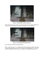
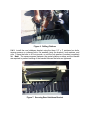
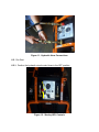
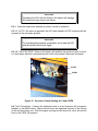
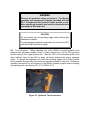
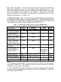
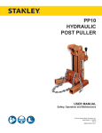
FROM:
HQ AFCESA/CES
139 Barnes Drive Suite 1
Tyndall AFB FL 32403-5319
SUBJECT:
Engineering Technical Letter (ETL) 98-10: Installation and Operation
Guide for the Stanley Hydraulic Power Unit (HPU) (Mobile Aircraft
Arresting System (MAAS) Upgrade)
1. Purpose. This ETL provides a detailed installation guide for mounting the Stanley
HP-1 Compact Hydraulic Power Unit on the Mobile Aircraft Arresting System (MAAS),
operating instructions for the new HPU and its ancillary equipment, and a replacement
equipment parts listing. The Stanley HP-1 HPU replaces the Wacker HPU originally
supplied with the MAAS.
2. Application: All Air Force installations.
2.1. Authority: AFPD 32-10, Air Force Installations and Facilities.
2.2. Effective Date: Immediately.
2.3. Expiration: Will be rescinded upon publication of the supplement to Technical
Order (TO) 35E8-2-10-1, 3, 4 containing these instructions.
2.4. Ultimate Recipients: All Air Force MAAS users.
2.5. Coordination: This ETL has been coordinated with San Antonio Air Logistics
Center, Ground Support Equipment Engineering Division (SA/ALC/LDEE), and the
Aeronautical Systems Center, Air Base Systems Division (ASC/WMO).
3. Referenced Publications: TO 35E8-2-10-1, Operation and Maintenance Instructions, Arresting Systems, Aircraft, Mobile.
4. System Description. The HPU provides power to raise and lower the MAAS
chassis and operate installation equipment such as hydraulic hammer drills and
hydraulic breakers, the stake removal tool, and the on-board winch. The Stanley HP 1
Compact Unit is designed to power Hydraulic Tool Manufacturers Association (HTMA)
Type l (5 gallons per minute (gpm) @ 2000 pounds per square inch (psi) and Type ll (8
gpm @ 2500 psi) hydraulic tools. The HP 1 comprises a nominally rated 8 gpm @ 2000
psi Intertech hydraulic pump, powered by an 18 horsepower Briggs and Stratton
unleaded gasoline engine. It has a 2.7-gallon hydraulic reservoir, and a 4.2-gallon fuel
capacity (3½ hours of continuous operation). The unit is 12 Vdc electric start, with an
optional pull starter kit available from Briggs and Stratton.
APPROVED FOR PUBLIC RELEASE: DISTRIBUTION UNLIMITED
Note: The pull starter option is strongly recommended for all Air Force activities to
ensure starting in event of battery failure.
5. Installation.
5.1. Remove Existing Trailer Hydraulic Connections. On the right (curb) side of the
MAAS trailer, locate the quick disconnect block. Remove and discard the existing
Series 56 male and female couplings, the flat washer, and the dust cap and plug.
Note: These components connect the 8-foot-long transmission hoses of the original
Wacker HPU to the trailer.
5.2. Install New Trailer Hydraulic Connections. Install the new series 49 male and
female couplers and tethered cap and plug set to the trailer quick disconnect.
Figure 1. MAAS Trailer Hydraulic Connections
5.3. Remove Existing Wacker HPU Holddown Brackets.
5.3.1. On each HPU platform, remove the two holddown brackets by removing the
bolts, nuts, and lock washers (four each). Discard the attaching hardware, latch
mechanisms, and bottom mounting plates.
Figure 2. Wacker HPU Holddown Brackets
5.3.2. Remove the center ½" bolt, nut, and lock washer from the center attachment of
the grate on the side opposite the breaker mounting post. Discard hardware.
Figure 3. Mounting Platform Bolt Removal
5.4. Install New HPU Rear Holddown Brackets.
5.4.1. Insert the new ½” x 3” stainless hex bolt up through the center hole in the
aluminum grated platform where the ½” bolt was removed (paragraph 4.3.2). Install the
rear HPU holddown bracket over the bolt; install the nut and tighten finger-tight only.
Figure 4. Positioning Rear Holddown Bracket
5.4.2. Align the rear HPU bracket parallel with the side support bracket of the grated
platform and mark the two outboard hole locations (center of slotted holes) in the bottom
brace of the side support bracket. Remove the previously installed ½” bolt (paragraph
5.4.1) and remove the rear HPU bracket. Drill the marked holes in the side support
bracket with a 9/16” drill bit.
Figure 5. Aligning Rear Holddown Bracket
Figure 6. Drilling Platform
5.4.3. Install the rear holddown bracket using the three 1/2” x 3” stainless hex bolts,
square spacers on outboard bolts, flat washers (atop the bracket), lock washers, and
nuts. Torque the bolts to 40 foot-pounds, or until the lock washer is crushed completely
flat. Note: The square spacers between the grated platform surface and the bracket
are required to prevent bending of the bracket base as the bolts are tightened.
Figure 7. Securing Rear Holddown Bracket
5.5. Install the Stanley HPU. Position the new Stanley HPU on the grated platform and
engage the rear cross member of the unit in the aft bracket. Insert the two retention
pins (positive lock) through the aft bracket to ensure proper positioning.
Figure 8. Positioning the Stanley HPU
5.6. Install New HPU Forward Holddown Brackets. Position the two front HPU brackets over
the front support legs (skid) of the Stanley HPU and on the grated platform to allow
installation of the eight (each) 5/16” x 2-1/4” bolts, flat washers, saddle clips, lock washers,
and nuts (bolts should be positioned through the 3rd, 5th, 15th, and 17th grate spaces,
counting inward from the edge of the platform). Ensure the retention pin lanyards are
attached under the bolts of the appropriate front brackets.
Figure 9. Mounting the Forward Holddown Brackets
Figure 10. Positive Lock Pin(s)
WARNING
Ensure all retention pins are installed and the HPU is
secure before moving the MAAS trailer.
5.7. Remove Hydraulic Hoses and Tools. Remove and discard the existing 50-foot and
8-foot hydraulic hoses. Remove the BH90 Breakers (two) and the HHB9 Hydraulic
Hammer Drill (two), including any drill bits (HHB9 bits will not fit the new Stanley
HD45110 Hammer Drill). Remaining on-board tools for the Wacker Pavement Breaker
will fit the new Stanley BR67130 Pavement Breaker and should remain on-board.
6. Operation.
WARNING
Review the Stanley Operations and Maintenance Manual
(provided with all HPUs and tools) before connecting or
operating any equipment.
Observe all safety
precautions and ensure MAAS operations are in
compliance with Technical Order 35E8-2-10-1.
6.1. Preliminary. Accomplish the actions in paragraphs 6.1.1 through 6.1.4 to prepare
the HP-1 for operation.
6.1.1. Check the hydraulic fluid reservoir to ensure it is full. Note: The unit is shipped
from the factory with the recommended hydraulic fluid. If hydraulic fluid is required,
Stanley Tools recommends any of the following:
•
•
•
•
AMS-Oil Hydraulic Fluid A/150 SSU, 100 V.I.
Chevron AW-MV-32
Exxon “Univis” J-26
Mobile D.T.E
Note: Refer to the Stanley HP1 Compact Manual for a complete list of approved fluids.
6.1.2. Fill the 4.2-gallon fuel tank with regular unleaded fuel.
CAUTION
Wear protective clothing and observe all safety precautions
while handling and charging the battery.
6.1.3. Remove the 12 Vdc battery supplied with the HPU. Fill the battery with
electrolyte and ensure the battery is adequately charged. Place the battery back onto
the HPU and secure with the hardware provided.
CAUTION
To prevent engine exhaust from damaging the neoprene
hoses, remove hoses from the basket before operating the
HPU.
6.1.4. Install the ½-inch diameter by 50-foot long, dual hydraulic hose assembly.
Attach the male and female Aeroquip 49 series couplers to the PRESSURE and
RETURN couplers on the dashboard of the HPU. The hoses will be stored in the hose
basket mounted atop the HPU. The opposite ends of the dual hoses are connected to
the trailer hydraulic connections that were installed on the curb side of the trailer chassis
(paragraph 5.2), or to one of the on-board Stanley tools. The HPU is supplied with one
pair of hydraulic hose connections (input and output), rather than the manifold system
(diverter valve) that is supplied with the Wacker HPU. This simplifies the hydraulic
connections, but requires that the hoses be manually changed from trailer operation to
one of the hydraulic tools.
Figure 11. Hydraulic Hose Connections
6.2. Pre-Start.
6.2.1. Position the hydraulic circuit control lever in the OFF position.
Control Lever Off
Position
Control Lever
Figure 12. Stanley HPU Controls
6.2.2. Select the AUTO throttle operating mode by positioning the governor lever so the guide
hole aligns with the appropriate hole in the cylinder lever, then insert the faspin.
AUTO
Figure 13. Governor Lever Automatic Position
6.3. Engine Start.
6.3.1. Place the ENGINE ON/OFF switch in the ON position. Place the hydraulic circuit
control lever in the START position. Engage the choke if necessary. When the engine
starts, release the control lever to the TOOL OFF position. Allow the engine to warm up
until it runs smoothly when the choke is released. Remove the hydraulic hoses from the
hose basket.
IMPORTANT
Make sure the control lever is in the
TOOL OFF position
before connecting
or
disconnecting
hoses at the tool.
DO NOT START THE
ENGINE WITH THE
GOVERNOR CONTROL
SET AT 8 GPM.
Toggle Switch ON
On
Choke
Start
Position
Figure 14. Starting the Stanley HPU
CAUTION
Operating the HPU with the hoses in the basket will damage
the hoses and may cause hose failure.
6.3.1. Once the engine has warmed up, select a mode of operation:
6.3.1.1. AUTO. No action is required if the HPU was started in AUTO mode and will be
operated in the automatic position.
CAUTION
To avoid damaging hydraulic components, do not start the HPU
with the throttle control set at 8 gpm.
6.3.1.2. HOLD 8/5 GPM. Remove the faspin and position the governor lever so the 8
or 5 hole aligns with the corresponding hole in the stop bracket, then insert the faspin.
5 GPM
8 GPM
Figure 15. Governor Control Setting for 5 and 8 GPM
6.4. Tools Connection. Connect the hydraulic hoses to a tool (hammer drill, pavement
breaker) or the MAAS trailer. Make sure all hoses are tightened securely to the fittings
at the tool and power unit. With the engine running and the choke off, move the control
lever to the TOOL ON position.
WARNING
Observe all applicable safety precautions. The Stanley
operation and maintenance manuals (provided with the
HP 1 Compact and the hydraulic tools) provide a complete operational scenario, and must be reviewed before
operating the HPU and tools.
CAUTION
Do not actuate the tool operating trigger without the proper
attachment installed.
To avoid damaging hydraulic components, do not start the HPU
with the throttle control set at 8 gpm.
6.5. Tools Operation. When operating any of the MAAS on-board hydraulic tools
(hammer drill, pavement breaker, winch, or stake removal tool), set the HPU governor
throttle setting in the 8 gpm position first. Start the HPU in the automatic position and
allow sufficient time for the HPU to warm up before selecting the proper operating
mode. To operate the hydraulic tools, hold the actuating trigger in the closed position
(this completes the hydraulic fluid circuit and permits operation of the tool). Review the
operating instructions for all functions of the MAAS hydraulic system before installing
and operating the new Stanley HPU (T.O. 35E8-2-10-1).
Figure 16. Hydraulic Tool Connection
6.6. Trailer Raise/Lower. Set the HPU governor throttle setting (for operating the
MAAS trailer raise/lower controls) in the automatic position. (paragraph 6.3.1.1). This
will provide sufficient operating pressure to activate the hydraulic cylinders that rotate
the axle assemblies up and away from the chassis. Operations for the trailer
raise/lower functions (four way valves) are identical to the operating instructions for the
Wacker HPU identified in T.O. 35E8-2-10-1.
7. Replacement Items. Table 1 lists part numbers and National Stock Numbers (NSN) for
items required to modify the MAAS to accept the Stanley HPU. Table 2 lists items that must
be removed from the MAAS trailer and replaced with the Stanley equipment. Table 3 lists
existing MAAS tools and accessories compatible with the Stanley HPU.
Table 1. New Equipment Required to Upgrade MAAS Trailer
Part
Number
HP18299
National
Stock Number
None
Units
per Trailer
2
CAGE
Code
54252
Pull starter, manual,
Briggs & Stratton engine
808087
None
2
08645
Flywheel cup, Briggs &
Stratton engine
805877
none
2
08645
50 foot x ½ inch dual
hydraulic hoses with
series 49 coupler ends
31848
None
2
54252
Series 49 tethered cap
and plug set
03288
None
1
54252
Series 49 Aeroquip
coupler set (male and
female) 3/8" NPT
24069
None
4
(as required
for additional
tools)
54252
Breaker, pavement
BR67130
3820-01-159-5470
2
54252
Hammer drill, hydraulic
HD45110
5130-01-178-6338
2
54252
Carbide drill bit (1"x 24")
02281
5130-00-061-4115
4
54252
Mounting brackets
MHU-1
None
2
None
Nomenclature
Hydraulic power unit,
HP-1, with hose basket
Notes:
1. The Pavement Breaker BR67130 and the Hammer Drill HD45110 hoses will have
3/8 inch NPT male ends. The connectors Stanley provides are known as flush face
connectors and do not use dust caps/plugs.
2. The specification and design package (and a source of supply) for the holddown
brackets has been validated and is available from HQ AFCESA/CEMR. Contact Mr.
John Smith at DSN 523-3865.
Table 2. Equipment to be Removed from MAAS Trailer
T.O.
35E8-2-10-4
Nomenclature Illustration Part Number
National
Stock Number
Units
per
Trailer
1
CAGE
Code
1
51506
Coupling,
female,
Series 56
19-17
5601-6-6S
Washer, flat
19-18
495-060-A3
Dust cap
19-20
5657-6
5340-00-071-3829
1
01276
Dust cap
19-21
5659-6
5340-00-071-3830
1
01276
Coupling,
male, Series
56
19-39
5602-6-6S
4730-01-063-9285
1
01276
Wacker HPU
19-1
52D9014-101
4940-01-356-3478
2
21439
Hose assy
30-7
52C8620-1
4720-01-254-0957
2
21439
Hose assy
30-13
52C8621-1
4720-01-255-7799
2
21439
Breaker
20-3
BH90
1710-01-315-0463
2
28792
Hammer drill
30-5
52B9493-1
5130-01-307-1108
2
21439
Bit, helical
30-4
5620072
5130-01-253-6345
4
11239
Hook
19-3
52B10766-1
5340-01-309-6248
4
21439
Tension latch
19-4
37L33-1-4AB
4
71286
Nut, hex (AP)
19-4
01857-002
16
21439
Screw (AP)
19-4
18257-043
16
21439
Lockwasher
19-4
14218-004
16
21439
Plate
19-5
52B10768-1
8
21439
Lateral
restraint assy
19-9
52B11041-1
4
21439
4730-00-939-5533
5305-01-254-9062
1710-01-309-6214
01276
Table 3. Wacker Tools Compatible with the Stanley HPU Equipment
T.O.
35E8-2-10-4
Nomenclature Illustration Part Number
National
Stock Number
CAGE
Code
2
85416
Stake driver
30-8
52C7235-1
Driver shank,
1¼"
30-9
310
Spade, clay
30-10
275
3820-01-254-9848
1
85416
Chisel, digging
30-11
270
3820-01-254-9846
2
85416
Moil point
30-12
163
3820-01-254-9847
1
85416
27
52D-9002-101
1710-01-255-3246
1
21439
Stake puller
5120-01-305-1855
Units
per
Trailer
2
21439
8. Points of Contact. Mr. John W. Smith, HQ AFCESA/CEMR, DSN 523-3865,
commercial (850)283-3865, Internet [email protected]; or Mr. Michael D. Ates, HQ
AFCESA/CESC, DSN 523-6351, commercial (850)283-6351, Internet
[email protected].
Lance C. Brendel, Colonel, USAF
Director of Technical Support
2 Atch
1. Optional Stanley Hydraulic Tools
2. Distribution List
Optional Stanley Hydraulic Tools
A1. Background. During operational test and evaluation of the Stanley HPU,
ASC/WMO and SA-ALC/LDEE learned of two additional Stanley tools that can enhance
MAAS installation and removal. These tools replace the existing MAAS hydraulic
breaker and driver shank, and the stake-removal tool. ASC/WMO and SA-ALC/LDE
representatives worked with engineering representatives from Stanley Tool Works to
further develop and evaluate these tools. They found that the performance of these
modified tools was much better than the original equipment supplied with MAAS. The
optional tools are identified as the PD48142 Post Driver, and the PP10100A Post Puller.
The San Antonio Air Logistics Center, Ground Support Equipment Engineering Division
(SA-ALC/LDEE) approved these tools for use with MAAS that have been equipped with
the Stanley HPU.
A2. PD48142 Post Driver. The PD48142 Post Driver is a Stanley PD45142 Post
Driver fitted with a larger piston and anvil. Use of this tool eliminates the need for the
technician to stand on top of the work stand to drive stakes, as shown in Figure A1.
Figure A1. Driving Stakes from the MAAS Work Stand
Atch 1
(1 of 4)
The PD48142 Driver has a 7.75-inch-deep cup that fits on top of the cruciform stake
and is operated by personnel standing on the ground as shown in Figure A2.
Figure A2. Driving Stakes Using the PD48142
A3. PP10100 Post Puller. The PP10100A is a Stanley PP10100 Post Puller with a
lengthened base weldment. The base is also modified to accept an additional vertical
leg that can be pinned at four different positions. The upper three holes in the leg allow
the operator to adjust the leg to stabilize the puller when removing moil points. The
lower hole in the leg allows the operator to adjust the angle of the puller to
approximately 15° when removing stakes (see Figures A3 and A4). The post puller has
an additional guide approximately one foot above the modified grip-jaws to support the
stake during removal. This reduces the twisting moment incurred when removing
stakes with the existing stake removal tool, and causes less damage to the stakes.
Atch 1
(2 of 4)
Figure A3. Stanley PP10 Base Weldment (Left), Stanley PP10100A
Modified Base (Right)
18"
14"
Figure A4. PP10100A Vertical Leg
Atch 1
(3 of 4)
Figure A5. PP10100A Post Puller
Note: Users should substitute only one signpost driver per trailer. One breaker must
be retained on each trailer for installation of moil point anchors used during asphaltover-soil installations.
WARNING
Users must read the manufacturer's manual
before connecting or operating these tools and
observe all applicable safety precautions.
A4. Operation and Maintenance of the PD48142 and the PP10100A. The PD45
Post Driver and the PP10 Post Puller are supplied with Stanley commercial manuals
and Stanley supplements PD48 Post Driver, and PP10100A Post Puller. Operation and
maintenance of the optional Stanley tools is covered within these commercial manuals
and there are no unique requirements for use of these tools with MAAS.
Atch 1
(4 of 4)
DISTRIBUTION LIST
DEPARTMENT OF DEFENSE
Defense Commissary Service
Director of Facilities
Bldg 8400
Lackland AFB TX 78236-5000
(1)
AAFES/ATTN: CFE
PO Box 660320
Dallas TX 75266-0320
(1)
Defense Technical Information
Center
ATTN: DTIC-FDA
Alexandria VA 22034-6145
(1)
SPECIAL INTEREST ORGANIZATIONS
IHS (S. Carter)
15 Inverness Way East Stop A-111
Englewood CO 80112
(1)
Construction Criteria Database
National Institute of Bldg Sciences
1201 L Street NW, Suite 400
Washington DC 20005
Atch 1
(1 of 1)
(1)