1
R
Setup Guide
P4280 Line Matrix Printer
P4280 Line Matrix Printer
Setup Guide
R
P/N 151772–001, Rev C
US and CANADA Radio Interference Note
Note: This device complies with Part 15 of the FCC Rules. Operation is subject to the following two
conditions: (1) this device may not cause harmful interference, and (2) this device must accept any
interference received, including interference that may cause undesired operation.
Properly shielded and grounded cables and connectors must be used in order to meet FCC emission limits.
The manufacturer is not responsible for any radio or television interference caused by using other than
recommended cables and connectors or by unauthorized changes or modifications to this equipment.
Unauthorized changes or modifications could void the user’s authority to operate the equipment.
The input/output (I/O) cable must be shielded for the printer to comply with FCC rules and regulations Part
15 governing the radiation limits for Class “A” equipment.
This Class A digital apparatus meets all requirements of the Canadian Interference–Causing Equipment
Regulations.
Cet appareil numérique de la classe A respecte toutes les exigences du Règlement sur le matériel brouilleur
du Canada.
WARNING
This is a Class A product. In a domestic environment this product may cause radio interference in which
case the user may be required to take adequate measures.
Printronix, Inc. makes no representations or warranties of any kind regarding this material, including, but not
limited to, implied warranties of merchantability and fitness for a particular purpose. Printronix, Inc. shall not
be held responsible for errors contained herein or any omissions from this material or for any damages,
whether direct, indirect, incidental or consequential, in connection with the furnishing, distribution,
performance or use of this material. The information in this manual is subject to change without notice.
This document contains proprietary information protected by copyright. No part of this document may be
reproduced, copied, translated or incorporated in any other material in any form or by any means, whether
manual, graphic, electronic, mechanical or otherwise, without the prior written consent of Printronix, Inc.
All rights reserved. Revision C. January, 1996.
Trademark Acknowledgements
IBM is a registered trademark of International Business Machines Corporation.
IGP is a trademark of Printronix, Inc.
RibbonMinder is a trademark of Printronix, Inc.
Printronix is a registered trademark of Printronix, Inc.
QMS is a registered trademark of QMS, Inc.
Code V is a trademark of QMS, Inc.
17500 Cartwright Road, P.O. Box 19559
Irvine, California 92713
Telephone (714) 863–1900 FAX (714) 660–8682
Technical Support (714) 221–2686
COPYRIGHT 1994, 1995, 1996 PRINTRONIX, INC.
Table of Contents
1
Introduction
About This Setup Guide . . . . . . . . . . . . . . . . . . . . . . . . . . . . . . . . . . . . . . . . . 1–2
How to Locate Information . . . . . . . . . . . . . . . . . . . . . . . . . . . . . . . . . . . 1–2
Warnings and Special Information . . . . . . . . . . . . . . . . . . . . . . . . . . . . . . 1–2
Keys and Display Messages . . . . . . . . . . . . . . . . . . . . . . . . . . . . . . . . . . . 1–3
Related Documents . . . . . . . . . . . . . . . . . . . . . . . . . . . . . . . . . . . . . . . . . 1–3
The P4280 Line Matrix Printer . . . . . . . . . . . . . . . . . . . . . . . . . . . . . . . . . . . . 1–4
Standard Features . . . . . . . . . . . . . . . . . . . . . . . . . . . . . . . . . . . . . . . . . . . . . . 1–5
General . . . . . . . . . . . . . . . . . . . . . . . . . . . . . . . . . . . . . . . . . . . . . . . . . . . 1–5
Host Computer Interface . . . . . . . . . . . . . . . . . . . . . . . . . . . . . . . . . . . . . 1–5
Printer Command and Control . . . . . . . . . . . . . . . . . . . . . . . . . . . . . . . . . 1–5
Output Control . . . . . . . . . . . . . . . . . . . . . . . . . . . . . . . . . . . . . . . . . . . . . 1–5
Graphics and Vertical Formatting . . . . . . . . . . . . . . . . . . . . . . . . . . . . . . 1–6
Built-in Diagnostic Tools . . . . . . . . . . . . . . . . . . . . . . . . . . . . . . . . . . . . . 1–6
Optional Features . . . . . . . . . . . . . . . . . . . . . . . . . . . . . . . . . . . . . . . . . . . . . . 1–7
Protocols and Emulations . . . . . . . . . . . . . . . . . . . . . . . . . . . . . . . . . . . . . . . . 1–8
Protocols . . . . . . . . . . . . . . . . . . . . . . . . . . . . . . . . . . . . . . . . . . . . . . . . . . 1–8
Emulations . . . . . . . . . . . . . . . . . . . . . . . . . . . . . . . . . . . . . . . . . . . . . . . . 1–8
2
Setting Up the Printer
Before You Begin . . . . . . . . . . . . . . . . . . . . . . . . . . . . . . . . . . . . . . . . . . . . . . 2–2
Select a Site . . . . . . . . . . . . . . . . . . . . . . . . . . . . . . . . . . . . . . . . . . . . . . . . . . . 2–2
Remove the Shipping Restraints . . . . . . . . . . . . . . . . . . . . . . . . . . . . . . . . . . . 2–5
Release the Paper Chains . . . . . . . . . . . . . . . . . . . . . . . . . . . . . . . . . . . . . . . . 2–10
Connect the Power Cord . . . . . . . . . . . . . . . . . . . . . . . . . . . . . . . . . . . . . . . . . 2–11
Connect the Interface Cable . . . . . . . . . . . . . . . . . . . . . . . . . . . . . . . . . . . . . . 2–12
Load the Paper . . . . . . . . . . . . . . . . . . . . . . . . . . . . . . . . . . . . . . . . . . . . . . . . 2–13
Set the Top of Form . . . . . . . . . . . . . . . . . . . . . . . . . . . . . . . . . . . . . . . . . . . . 2–18
Table of Contents
i
Install the Ribbon . . . . . . . . . . . . . . . . . . . . . . . . . . . . . . . . . . . . . . . . . . . . . . 2–20
Test the Printer . . . . . . . . . . . . . . . . . . . . . . . . . . . . . . . . . . . . . . . . . . . . . . . . 2–22
3
Configuring the Printer
Overview . . . . . . . . . . . . . . . . . . . . . . . . . . . . . . . . . . . . . . . . . . . . . . . . . . . . . 3–5
Operating States . . . . . . . . . . . . . . . . . . . . . . . . . . . . . . . . . . . . . . . . . . . . 3–7
The Configurations . . . . . . . . . . . . . . . . . . . . . . . . . . . . . . . . . . . . . . . . . . 3–7
Unlocking the ENTER Key . . . . . . . . . . . . . . . . . . . . . . . . . . . . . . . . . . . 3–8
Locking the ENTER Key . . . . . . . . . . . . . . . . . . . . . . . . . . . . . . . . . . . . . 3–8
Saving Parameters . . . . . . . . . . . . . . . . . . . . . . . . . . . . . . . . . . . . . . . . . . 3–9
Factory Default Configuration Values . . . . . . . . . . . . . . . . . . . . . . . . . . . . . . 3–10
Printing the Current Configuration . . . . . . . . . . . . . . . . . . . . . . . . . . . . . . . . . 3–12
Changing Configuration Values . . . . . . . . . . . . . . . . . . . . . . . . . . . . . . . . . . . 3–14
Saving Your New Configuration . . . . . . . . . . . . . . . . . . . . . . . . . . . . . . . . . . 3–17
Loading Predefined Configurations . . . . . . . . . . . . . . . . . . . . . . . . . . . . . . . . 3–19
Loading Customized Configurations . . . . . . . . . . . . . . . . . . . . . . . . . . . . . . . 3–22
Resetting the Printer to Default or Saved Parameters . . . . . . . . . . . . . . . . . . 3–23
Configuration Menu Diagrams . . . . . . . . . . . . . . . . . . . . . . . . . . . . . . . . . . . 3–24
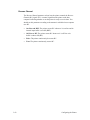
Ribbon Life Menu Options . . . . . . . . . . . . . . . . . . . . . . . . . . . . . . . . . . . . . . . 3–26
New Ribbon . . . . . . . . . . . . . . . . . . . . . . . . . . . . . . . . . . . . . . . . . . . . . . . 3–27
Set Job Rate . . . . . . . . . . . . . . . . . . . . . . . . . . . . . . . . . . . . . . . . . . . . . . . 3–27
Analyze Job . . . . . . . . . . . . . . . . . . . . . . . . . . . . . . . . . . . . . . . . . . . . . . . 3–27
Set Ribbon Size . . . . . . . . . . . . . . . . . . . . . . . . . . . . . . . . . . . . . . . . . . . . 3–27
When Worn Action . . . . . . . . . . . . . . . . . . . . . . . . . . . . . . . . . . . . . . . . . . 3–27
Enable/Disable . . . . . . . . . . . . . . . . . . . . . . . . . . . . . . . . . . . . . . . . . . . . . 3–28
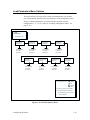
Font Menu Options . . . . . . . . . . . . . . . . . . . . . . . . . . . . . . . . . . . . . . . . . . . . . 3–28
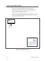
Character Set Menu Options . . . . . . . . . . . . . . . . . . . . . . . . . . . . . . . . . . . . . . 3–30
Application Compatibility Menu Options . . . . . . . . . . . . . . . . . . . . . . . . . . . 3–32
Printer Protocol . . . . . . . . . . . . . . . . . . . . . . . . . . . . . . . . . . . . . . . . . . . . 3–34
Buffer Size . . . . . . . . . . . . . . . . . . . . . . . . . . . . . . . . . . . . . . . . . . . . . . . . 3–34
Uppercase Select . . . . . . . . . . . . . . . . . . . . . . . . . . . . . . . . . . . . . . . . . . . 3–35
Printer Select . . . . . . . . . . . . . . . . . . . . . . . . . . . . . . . . . . . . . . . . . . . . . . 3–35
ii
Table of Contents
Paper Advance SW (Switch) . . . . . . . . . . . . . . . . . . . . . . . . . . . . . . . . . . 3–36
Power On State . . . . . . . . . . . . . . . . . . . . . . . . . . . . . . . . . . . . . . . . . . . . . 3–36
Alarm On Fault . . . . . . . . . . . . . . . . . . . . . . . . . . . . . . . . . . . . . . . . . . . . 3–37
Shuttle Timeout . . . . . . . . . . . . . . . . . . . . . . . . . . . . . . . . . . . . . . . . . . . . 3–37
Unidirectional . . . . . . . . . . . . . . . . . . . . . . . . . . . . . . . . . . . . . . . . . . . . . . 3–37
Select SFCC . . . . . . . . . . . . . . . . . . . . . . . . . . . . . . . . . . . . . . . . . . . . . . . 3–38
80–9F Hex . . . . . . . . . . . . . . . . . . . . . . . . . . . . . . . . . . . . . . . . . . . . . . . . 3–38
Control Code 06 . . . . . . . . . . . . . . . . . . . . . . . . . . . . . . . . . . . . . . . . . . . . 3–38
Control Code 08 . . . . . . . . . . . . . . . . . . . . . . . . . . . . . . . . . . . . . . . . . . . . 3–39
Overstrike . . . . . . . . . . . . . . . . . . . . . . . . . . . . . . . . . . . . . . . . . . . . . . . . . 3–39
Compress Print . . . . . . . . . . . . . . . . . . . . . . . . . . . . . . . . . . . . . . . . . . . . . 3–40
Draft Print . . . . . . . . . . . . . . . . . . . . . . . . . . . . . . . . . . . . . . . . . . . . . . . . . 3–40
Font Select/Elongated . . . . . . . . . . . . . . . . . . . . . . . . . . . . . . . . . . . . . . . 3–41
View . . . . . . . . . . . . . . . . . . . . . . . . . . . . . . . . . . . . . . . . . . . . . . . . . . . . . 3–41
Display Language . . . . . . . . . . . . . . . . . . . . . . . . . . . . . . . . . . . . . . . . . . . 3–41
Paper Format Menu Options . . . . . . . . . . . . . . . . . . . . . . . . . . . . . . . . . . . . . . 3–42
Line Spacing . . . . . . . . . . . . . . . . . . . . . . . . . . . . . . . . . . . . . . . . . . . . . . . 3–43
Form Length Set . . . . . . . . . . . . . . . . . . . . . . . . . . . . . . . . . . . . . . . . . . . . 3–43
Auto Line Feed . . . . . . . . . . . . . . . . . . . . . . . . . . . . . . . . . . . . . . . . . . . . . 3–44
Define CR (Carriage Return) Code . . . . . . . . . . . . . . . . . . . . . . . . . . . . . 3–44
Define LF (Line Feed) Code . . . . . . . . . . . . . . . . . . . . . . . . . . . . . . . . . . 3–44
VFU (Vertical Format Unit) Select . . . . . . . . . . . . . . . . . . . . . . . . . . . . . 3–45
VFU (Vertical Format Unit) Table . . . . . . . . . . . . . . . . . . . . . . . . . . . . . . 3–46
Perforation Skip . . . . . . . . . . . . . . . . . . . . . . . . . . . . . . . . . . . . . . . . . . . . 3–46
Paper Out . . . . . . . . . . . . . . . . . . . . . . . . . . . . . . . . . . . . . . . . . . . . . . . . . 3–46
Paperout Adjust . . . . . . . . . . . . . . . . . . . . . . . . . . . . . . . . . . . . . . . . . . . . 3–47
PMD (Paper Motion Detection) Fault . . . . . . . . . . . . . . . . . . . . . . . . . . . 3–47
Slew Relative . . . . . . . . . . . . . . . . . . . . . . . . . . . . . . . . . . . . . . . . . . . . . . 3–48
Print Width . . . . . . . . . . . . . . . . . . . . . . . . . . . . . . . . . . . . . . . . . . . . . . . . 3–48
Host Interface Menu Options . . . . . . . . . . . . . . . . . . . . . . . . . . . . . . . . . . . . . 3–50
Centronics Menu Options . . . . . . . . . . . . . . . . . . . . . . . . . . . . . . . . . . . . . . . . 3–51
Data Bit 8 . . . . . . . . . . . . . . . . . . . . . . . . . . . . . . . . . . . . . . . . . . . . . . . . . 3–52
PI (Paper Instruction) Line . . . . . . . . . . . . . . . . . . . . . . . . . . . . . . . . . . . . 3–52
Table of Contents
iii
Data Polarity . . . . . . . . . . . . . . . . . . . . . . . . . . . . . . . . . . . . . . . . . . . . . . . 3–53
Response Polarity . . . . . . . . . . . . . . . . . . . . . . . . . . . . . . . . . . . . . . . . . . . 3–53
Fast Busy . . . . . . . . . . . . . . . . . . . . . . . . . . . . . . . . . . . . . . . . . . . . . . . . . 3–53
Strobe Polarity . . . . . . . . . . . . . . . . . . . . . . . . . . . . . . . . . . . . . . . . . . . . . 3–54
Latch Data On . . . . . . . . . . . . . . . . . . . . . . . . . . . . . . . . . . . . . . . . . . . . . 3–54
Dataproducts Menu Options . . . . . . . . . . . . . . . . . . . . . . . . . . . . . . . . . . . . . . 3–55
Data Bit 8 . . . . . . . . . . . . . . . . . . . . . . . . . . . . . . . . . . . . . . . . . . . . . . . . . 3–56
PI (Paper Instruction) Line . . . . . . . . . . . . . . . . . . . . . . . . . . . . . . . . . . . . 3–56
Data Polarity . . . . . . . . . . . . . . . . . . . . . . . . . . . . . . . . . . . . . . . . . . . . . . . 3–56
Response Polarity . . . . . . . . . . . . . . . . . . . . . . . . . . . . . . . . . . . . . . . . . . . 3–57
Strobe Polarity . . . . . . . . . . . . . . . . . . . . . . . . . . . . . . . . . . . . . . . . . . . . . 3–57
Latch Data On . . . . . . . . . . . . . . . . . . . . . . . . . . . . . . . . . . . . . . . . . . . . . 3–57
Serial RS-232 Menu Options . . . . . . . . . . . . . . . . . . . . . . . . . . . . . . . . . . . . . 3–58
Data Protocol . . . . . . . . . . . . . . . . . . . . . . . . . . . . . . . . . . . . . . . . . . . . . . 3–59
Data Rate . . . . . . . . . . . . . . . . . . . . . . . . . . . . . . . . . . . . . . . . . . . . . . . . . 3–59
Word Length . . . . . . . . . . . . . . . . . . . . . . . . . . . . . . . . . . . . . . . . . . . . . . . 3–59
Stop Bit . . . . . . . . . . . . . . . . . . . . . . . . . . . . . . . . . . . . . . . . . . . . . . . . . . . 3–60
Parity . . . . . . . . . . . . . . . . . . . . . . . . . . . . . . . . . . . . . . . . . . . . . . . . . . . . 3–60
Bit 8 Function . . . . . . . . . . . . . . . . . . . . . . . . . . . . . . . . . . . . . . . . . . . . . . 3–60
Data Term Ready . . . . . . . . . . . . . . . . . . . . . . . . . . . . . . . . . . . . . . . . . . . 3–61
Request to Send . . . . . . . . . . . . . . . . . . . . . . . . . . . . . . . . . . . . . . . . . . . . 3–61
Reverse Channel . . . . . . . . . . . . . . . . . . . . . . . . . . . . . . . . . . . . . . . . . . . . 3–62
Load Parameters Menu Options . . . . . . . . . . . . . . . . . . . . . . . . . . . . . . . . . . . 3–63
Load Saved Parameters (1, 2, 3, or 4) . . . . . . . . . . . . . . . . . . . . . . . . . . . 3–64
Load IGP Parameters . . . . . . . . . . . . . . . . . . . . . . . . . . . . . . . . . . . . . . . . 3–64
Load IBM 3287 Parameters . . . . . . . . . . . . . . . . . . . . . . . . . . . . . . . . . . . 3–64
Load IBM 5225 Parameters . . . . . . . . . . . . . . . . . . . . . . . . . . . . . . . . . . . 3–64
Load Factory Parameters . . . . . . . . . . . . . . . . . . . . . . . . . . . . . . . . . . . . . 3–65
Save Parameters Menu Options . . . . . . . . . . . . . . . . . . . . . . . . . . . . . . . . . . . 3–66
Diagnostics Menu Options . . . . . . . . . . . . . . . . . . . . . . . . . . . . . . . . . . . . . . . 3–67
iv
Table of Contents
4
Printer Interfaces
Overview . . . . . . . . . . . . . . . . . . . . . . . . . . . . . . . . . . . . . . . . . . . . . . . . . . . . . 4–2
Dataproducts Parallel Interface . . . . . . . . . . . . . . . . . . . . . . . . . . . . . . . . . . . . 4–3
Dataproducts Parallel Interface Signals . . . . . . . . . . . . . . . . . . . . . . . . . . 4–4
Dataproducts Parallel Interface Configuration . . . . . . . . . . . . . . . . . . . . . 4–5
Centronics Parallel Interface . . . . . . . . . . . . . . . . . . . . . . . . . . . . . . . . . . . . . . 4–6
Centronics Parallel Interface Signals . . . . . . . . . . . . . . . . . . . . . . . . . . . . 4–7
Centronics Parallel Interface Configuration . . . . . . . . . . . . . . . . . . . . . . . 4–8
Alternate Terminating Resistors . . . . . . . . . . . . . . . . . . . . . . . . . . . . . . . . . . . 4–9
Removal and Installation . . . . . . . . . . . . . . . . . . . . . . . . . . . . . . . . . . . . . 4–9
RS-232 Serial Interface . . . . . . . . . . . . . . . . . . . . . . . . . . . . . . . . . . . . . . . . . . 4–10
RS-232 Serial Interface Signals . . . . . . . . . . . . . . . . . . . . . . . . . . . . . . . . 4–10
RS-232 Serial Interface Protocols . . . . . . . . . . . . . . . . . . . . . . . . . . . . . . 4–11
RS-232 Serial Interface Error Handling . . . . . . . . . . . . . . . . . . . . . . . . . . 4–12
RS-232 Serial Interface Configuration . . . . . . . . . . . . . . . . . . . . . . . . . . . 4–13
5
Routine Service and Diagnostics
Overview . . . . . . . . . . . . . . . . . . . . . . . . . . . . . . . . . . . . . . . . . . . . . . . . . . . . . 5–2
Cleaning Requirements . . . . . . . . . . . . . . . . . . . . . . . . . . . . . . . . . . . . . . . . . . 5–2
Cleaning Outside the Cabinet . . . . . . . . . . . . . . . . . . . . . . . . . . . . . . . . . . 5–2
Cleaning Inside the Cabinet . . . . . . . . . . . . . . . . . . . . . . . . . . . . . . . . . . . 5–3
Diagnostic Tests . . . . . . . . . . . . . . . . . . . . . . . . . . . . . . . . . . . . . . . . . . . . . . . 5–6
Configuration Printout . . . . . . . . . . . . . . . . . . . . . . . . . . . . . . . . . . . . . . . 5–8
Print Data Stream in Hex Code . . . . . . . . . . . . . . . . . . . . . . . . . . . . . . . . 5–9
Printer Test 8 Inch Width . . . . . . . . . . . . . . . . . . . . . . . . . . . . . . . . . . . . . 5–9
Printer Test Full Width . . . . . . . . . . . . . . . . . . . . . . . . . . . . . . . . . . . . . . . 5–9
Print Statistics . . . . . . . . . . . . . . . . . . . . . . . . . . . . . . . . . . . . . . . . . . . . . . 5–9
Running the Diagnostic Tests . . . . . . . . . . . . . . . . . . . . . . . . . . . . . . . . . . 5–11
Printing Hex Code . . . . . . . . . . . . . . . . . . . . . . . . . . . . . . . . . . . . . . . . . . . . . 5–13
Fault Messages . . . . . . . . . . . . . . . . . . . . . . . . . . . . . . . . . . . . . . . . . . . . . . . . 5–16
Table of Contents
v
6
RibbonMinder
Overview . . . . . . . . . . . . . . . . . . . . . . . . . . . . . . . . . . . . . . . . . . . . . . . . . . . . . 6–2
Running a Job . . . . . . . . . . . . . . . . . . . . . . . . . . . . . . . . . . . . . . . . . . . . . . 6–3
Configuring the RibbonMinder . . . . . . . . . . . . . . . . . . . . . . . . . . . . . . . . . . . 6–4
Setting Up a New Ribbon . . . . . . . . . . . . . . . . . . . . . . . . . . . . . . . . . . . . . . . . 6–6
Setting Ribbon Size . . . . . . . . . . . . . . . . . . . . . . . . . . . . . . . . . . . . . . . . . . . . 6–8
Enabling and Disabling RibbonMinder . . . . . . . . . . . . . . . . . . . . . . . . . . . . . 6–10
When Worn Action . . . . . . . . . . . . . . . . . . . . . . . . . . . . . . . . . . . . . . . . . . . . . 6–12
Analyzing Jobs . . . . . . . . . . . . . . . . . . . . . . . . . . . . . . . . . . . . . . . . . . . . . . . . 6–14
Setting Analyze Job Mode . . . . . . . . . . . . . . . . . . . . . . . . . . . . . . . . . . . . 6–15
Analyzing Jobs Quickly . . . . . . . . . . . . . . . . . . . . . . . . . . . . . . . . . . . . . . 6–17
Setting the Job Rate . . . . . . . . . . . . . . . . . . . . . . . . . . . . . . . . . . . . . . . . . . . . 6–18
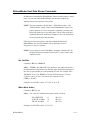
RibbonMinder Host Data Stream Commands . . . . . . . . . . . . . . . . . . . . . . . . 6–21
Set Job Rate . . . . . . . . . . . . . . . . . . . . . . . . . . . . . . . . . . . . . . . . . . . . . . . 6–21
When Worn Action . . . . . . . . . . . . . . . . . . . . . . . . . . . . . . . . . . . . . . . . . . 6–21
Enable/Disable . . . . . . . . . . . . . . . . . . . . . . . . . . . . . . . . . . . . . . . . . . . . . 6–22
Appendices
A
Printer Specifications
B
A Quick Look at Line Matrix Printing
C
ASCII Character Set
D
Predefined Configuration Values
Glossary
Index
vi
Table of Contents
1
Introduction
Chapter Contents
About This Setup Guide . . . . . . . . . . . . . . . . . . . . . . . . . . . . . . . . . . . . . . . . . 1–2
How to Locate Information . . . . . . . . . . . . . . . . . . . . . . . . . . . . . . . . . . . 1–2
Warnings and Special Information . . . . . . . . . . . . . . . . . . . . . . . . . . . . . . 1–2
Keys and Display Messages . . . . . . . . . . . . . . . . . . . . . . . . . . . . . . . . . . . 1–3
Related Documents . . . . . . . . . . . . . . . . . . . . . . . . . . . . . . . . . . . . . . . . . 1–3
The P4280 Line Matrix Printer . . . . . . . . . . . . . . . . . . . . . . . . . . . . . . . . . . . . 1–4
Standard Features . . . . . . . . . . . . . . . . . . . . . . . . . . . . . . . . . . . . . . . . . . . . . . 1–5
General . . . . . . . . . . . . . . . . . . . . . . . . . . . . . . . . . . . . . . . . . . . . . . . . . . . 1–5
Host Computer Interface . . . . . . . . . . . . . . . . . . . . . . . . . . . . . . . . . . . . . 1–5
Printer Command and Control . . . . . . . . . . . . . . . . . . . . . . . . . . . . . . . . . 1–5
Output Control . . . . . . . . . . . . . . . . . . . . . . . . . . . . . . . . . . . . . . . . . . . . . 1–5
Graphics and Vertical Formatting . . . . . . . . . . . . . . . . . . . . . . . . . . . . . . 1–6
Built-in Diagnostic Tools . . . . . . . . . . . . . . . . . . . . . . . . . . . . . . . . . . . . . 1–6
Optional Features . . . . . . . . . . . . . . . . . . . . . . . . . . . . . . . . . . . . . . . . . . . . . . 1–7
Protocols and Emulations . . . . . . . . . . . . . . . . . . . . . . . . . . . . . . . . . . . . . . . . 1–8
Protocols . . . . . . . . . . . . . . . . . . . . . . . . . . . . . . . . . . . . . . . . . . . . . . . . . . 1–8
Emulations . . . . . . . . . . . . . . . . . . . . . . . . . . . . . . . . . . . . . . . . . . . . . . . . 1–8
Introduction
1–1
About This Setup Guide
This Setup Guide is designed so you can quickly install and configure your
P4280 printer.
How to Locate Information
•
Use the Table of Contents at the front of this guide.
•
Use the Chapter Contents listed on the first page of each chapter.
•
Use the Glossary to learn the printer terms and acronyms in this Setup
Guide. The Glossary is located just before the Index at the back of this
guide.
•
Use the alphabetical Index at the back of this guide.
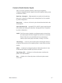
Warnings and Special Information
For your safety and to protect valuable equipment, it is very important that
you read and comply with all information highlighted under special
headings:
WARNING
Conditions that could harm you as well as damage the equipment.
CAUTION
Conditions that could damage the printer or related equipment.
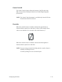
IMPORTANT
Information vital to proper operation of the printer.
NOTE: Information and helpful tips about printer operation.
1–2
Introduction
Keys and Display Messages
Keys and indicators that are labeled on the printer are printed in uppercase.
Example:
Press the ON LINE key.
Messages that appear on the Liquid Crystal Display (LCD) are enclosed in
quotation marks and printed with initial capital letters.
Example:
The message “Save Config” appears on the display.
Related Documents
For more information about your printer, refer to the following documents:
Introduction
•
P4280 Line Matrix Printer Operator’s Guide. Includes step-by-step
instructions on daily printer operations.
•
Impact Printers Programmer’s Reference Manual. Describes printer
codes and character sets for various printer emulation modes. This
manual will assist users who wish to create and send custom data streams
to the printer.
1–3
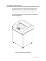
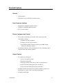
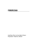
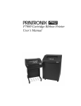
The P4280 Line Matrix Printer
The P4280 printer incorporates the latest refinements in line matrix printing
technology, yet is very easy to use. The LCD and Light Emitting Diodes
(LED) status indicators on the control panel communicate with you directly
and clearly. You can select every function on your printer at the control panel
or by sending commands from the host computer. The print mechanism is
housed in an insulated floor cabinet that makes this printer one of the quietest
impact printers in the world.
Figure 1–1. The P4280 Line Matrix Printer
1–4
Introduction
Standard Features
General
•
Quiet operation
•
Print speeds of up to 800 lines per minute (lpm)
Host Computer Interface
•
Dataproducts-compatible parallel interface
•
Centronics-compatible parallel interface
•
RS-232 serial interface
Printer Command and Control
•
Three printer emulations are selectable at the control panel and
controlled by software:
1) Printronix P-Series emulation
2) Printronix P-Series XQ emulation
3) Serial Matrix printer emulation (similar to the IBM Graphic
Printer, but with more features)
•
All emulation software, fonts, and character sets are permanently stored
in printer Read–Only Memory (ROM).
Output Control
•
Five modes for printing text:
1) Near-Letter Quality (NLQ)
2) Data Processing (DP)
3) High Speed (HS), with a choice of three vertical densities
4) Optical Character Recognition Font A (OCR-A)
5) Optical Character Recognition Font B (OCR-B)
Introduction
•
Selectable alternate horizontal and vertical dot densities enable you to
tailor output to a wider variety of printing requirements.
•
Selectable forms length
1–5
•
Character attribute specification:
1) Selectable pitch: normal, expanded, and compressed
2) Emphasized (“shadow”) printing
3) Double strike (bold) printing
4) Automatic underlining
5) Superscript and subscript printing
6) Double high printing
•
Resident multinational character sets
•
Downloadable character sets and international languages. You can add
international languages to the font library and access them in both
P-Series and Serial Matrix emulations.
•
RibbonMinder, a ribbon ink–life indicator
Graphics and Vertical Formatting
Several graphics and vertical formatting features are available:
•
Two built-in graphics generators:
1) P-Series odd-even dot Plot Mode
2) Bit-image graphics (serial matrix printer emulation)
•
Programmable electronic vertical formatting provides rapid vertical
paper movement to specified lines for printing repetitive and continuous
forms. You can choose from a variety of methods:
1) EVFU: Printronix Electronic Vertical Format Unit
2) DAVFU: Dataproducts-compatible Direct Access Vertical Format
Unit
3) NVFU: Printronix New direct access Vertical Format Unit
4) CVFU: Centronics-compatible direct access Vertical Format Unit
5) Vertical tabbing in Serial Matrix emulation mode
Built-in Diagnostic Tools
Several diagnostic tools are provided with the printer:
1–6
•
Comprehensive series of diagnostic self-tests permanently stored in ROM
•
Configuration printout
•
Test pattern printout
•
Data stream hex code printout
Introduction
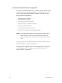
Optional Features
We offer a variety of options that enable you to fine-tune your printer to
nearly any printing application:
•
Intelligent Graphics Processor (IGP–200 and IGP–210). The IGP
processes and plots all graphics, freeing the host computer for other
tasks. You can create forms, bar codes, logos, expanded characters, and
other graphics. You can print sideways or upside down. You can print
forms with graphic components overlayed with alphanumeric and bar
code data, all in a single pass.
•
Coaxial/Twinaxial option: Allows the printer to emulate IBM 3287,
5225, and 4234 printers.
For more information, contact your sales representative.
Introduction
1–7
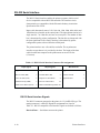
Protocols and Emulations
Protocols
A protocol is a set of rules governing the exchange of information between
the printer and its host computer. These rules consist of codes that
manipulate and print data and allow for machine-to-machine communication.
A printer and the its host computer must use the same protocol.
Most impact printers use single ASCII character codes to print text, numbers,
and punctuation marks. Some characters, both singly and in groups of two or
more, are defined as control codes. Control codes instruct the printer to
perform specific functions, such as underlining text, printing subscripts,
setting page margins, etc.
The principal difference between most printer protocols is in the characters
used to create control codes and the ways in which these characters are
formatted.
You can select the protocol at the control panel. The printer stores three
protocols in ROM:
•
Printronix P-Series
•
Serial Matrix
•
P-Series XQ
Emulations
When the printer executes the character and control codes of another printer
protocol, we say that it emulates that printer. If the printer uses the P-Series
protocol, for example, it is emulating a Printronix P-Series printer.
As used in this manual, protocol and emulation mean the same thing. If the
printer is using the Serial Matrix printer protocol, for example, we can also
say it is in Serial Matrix emulation mode.
For additional information, refer to the Impact Printers Programmer’s
Reference Manual.
1–8
Introduction
2
Setting Up the Printer
Chapter Contents
Before You Begin . . . . . . . . . . . . . . . . . . . . . . . . . . . . . . . . . . . . . . . . . . . . . . 2–2
Select a Site . . . . . . . . . . . . . . . . . . . . . . . . . . . . . . . . . . . . . . . . . . . . . . . . . . . 2–2
Remove the Shipping Restraints . . . . . . . . . . . . . . . . . . . . . . . . . . . . . . . . . . . 2–5
Release the Paper Chains . . . . . . . . . . . . . . . . . . . . . . . . . . . . . . . . . . . . . . . . 2–10
Connect the Power Cord . . . . . . . . . . . . . . . . . . . . . . . . . . . . . . . . . . . . . . . . . 2–11
Connect the Interface Cable . . . . . . . . . . . . . . . . . . . . . . . . . . . . . . . . . . . . . . 2–12
Load the Paper . . . . . . . . . . . . . . . . . . . . . . . . . . . . . . . . . . . . . . . . . . . . . . . . 2–13
Set the Top of Form . . . . . . . . . . . . . . . . . . . . . . . . . . . . . . . . . . . . . . . . . . . . 2–18
Install the Ribbon . . . . . . . . . . . . . . . . . . . . . . . . . . . . . . . . . . . . . . . . . . . . . . 2–20
Test the Printer . . . . . . . . . . . . . . . . . . . . . . . . . . . . . . . . . . . . . . . . . . . . . . . . 2–22
Setting Up the Printer
2–1
Before You Begin
Read this chapter carefully before installing and operating the printer.
The printer is easy to install, but for your safety and to protect valuable
equipment, perform all the procedures in this chapter in the order presented.
Select a Site
Select a printer site that meets the following requirements:
•
Has a power outlet that supplies either 50 or 60 Hz power, with a voltage
range of either 100 to 120 VAC or 200 to 240 VAC. The printer
automatically senses the power line voltage and adjusts itself to conform
to the correct voltage range.
Primary circuit protection is built-in; the power switch is also a circuit
breaker.
IMPORTANT
It is recommended that printer power be supplied from a separate 50 or
60 Hertz AC circuit. This circuit must have the proper overcurrent
protection (fuse or circuit breaker). Refer to page A–5 for the maximum
current requirements of the printer and other printer power
specifications.
2–2
•
Permits complete opening of the printer cover and both doors of the floor
cabinet.
•
Allows at least three feet of clearance behind the printer. (This permits
air to circulate freely around the printer and provides access to the paper
stacking area.)
•
Is relatively dust-free.
•
Has a temperature range of 10° C to 40° C (50° F to 104° F) and a
relative humidity from 10% to 90%.
Setting Up the Printer
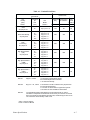
•
Is located within the maximum allowable distance to the host computer,
as shown below:
Type of Interface
Maximum Distance to
Host Computer
Dataproducts-compatible
parallel interface
12 meters (40 feet)
Centronics-compatible
parallel interface
5 meters (15 feet)
RS-232 serial interface
15 meters (50 feet)
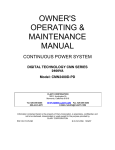
Printer dimensions are shown in Figure 2–1 on page 2–4.
Setting Up the Printer
2–3
Printer Cover
Cabinet Rear Door
146.1 cm
(57.5 in.)
104.1 cm
(41.0 in.)
57.2 cm
(22.5 in.)
73.7 cm
(29.0 in.)
191.5 cm
(75.4 in.)
68.6 cm
(27.0 in.)
68.6 cm
(27.0 in.)
Figure 2–1. Printer Dimensions
2–4
Setting Up the Printer
Remove the Shipping Restraints
WARNING
To prevent possible injury, do not connect the AC power source before
removing the shipping restraints. If the power source has already been
connected, disconnect it before performing the shipping restraint
removal procedures.
WARNUNG
Um mögliche Verletzungen zu vermeiden, darf die Netzverbindung erst
nach dem Entfernen der Transportbefestigungen hergestellt werden.
ATTENTION
Pour éviter tout danger, ne branchez pas le cordon d’alimentation avant
d’avoir ôté les cales de transport. Si l’alimentation est déjà raccordée,
débranchez–la avant d’effectuer les procédures d’enlèvement des cales.
CAUTION
To avoid shipping damage, reinstall the shipping restraints whenever
you move or ship the printer.
VORSICHT
Um Versandschäden zu verhindern, die Versand–Einspannungen wieder
einbauen, wenn der Drucker versetzt oder versand wird.
PRÉCAUTIONS
Pour éviter tout dégât lors du transport, remettez les cales en place
chaque fois que l’imprimante est déplacée ou transportée.
Tie wraps and foam pads protect the platen and tractors from damage during
shipment. You must remove these shipping restraints before you operate the
printer.
Save the foam pads and extra tie wraps with the other packing materials.
To reinstall the shipping restraints, simply reverse the steps in this section.
Setting Up the Printer
2–5
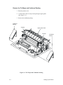
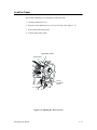
Remove the Tie Wraps and Cardboard Packing
1. Raise the printer cover.
2. Cut and remove the tie wraps securing the upper paper guide.
(See Figure 2–2.)
3. Remove the cardboard packing.
Cardboard
Packing
Tie Wrap
Upper Paper Guide
Tie Wrap
Cardboard
Packing
Figure 2–2. Tie Wraps and Cardboard Packing
2–6
Setting Up the Printer
Remove the Protective Film
Carefully peel the protective film off the control panel. (See Figure 2–3.)
Protective Film
Figure 2–3. Protective Film
Setting Up the Printer
2–7
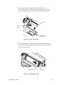
Remove the Platen Protective Foam
1. Open the left and right tractor gates. Push the tractor locks down. Move
the tractors outward as far as they will go. (See Figure 2–4.)
2. Rotate the forms thickness lever away from you as far as it will go; this
is the fully open position.
3. Rotate the platen protective foam toward the front of the printer and
remove it from under the tractor support shaft.
Platen Protective Foam
Tractor Support Shaft
Left Tractor Gate
Tractor Locks
Right Tractor Gate
Forms
Thickness
Lever
Figure 2–4. Platen Protective Foam
2–8
Setting Up the Printer
Remove the Hammer Bank Protective Foam
Rotate the hammer bank protective foam toward the front of the printer and
remove it from between the ribbon mask and hammer bank. (See
Figure 2–5.)
Hammer Bank
Protective Foam
Figure 2–5. Hammer Bank Protective Foam
Setting Up the Printer
2–9
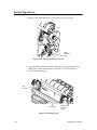
Release the Paper Chains
1. Open the rear cabinet door.
2. Cut the tie wraps and release the paper chains from the bags at the rear of
the printer frame. Remove the tie wraps and bags. (See Figure 2–6.)
3. Make sure each chain hangs freely, with no kinks or knots.
4. Close the rear cabinet door.
Tie Wrap
Tie Wrap
Plastic
Bags
Figure 2–6. Paper Chains
2–10
Setting Up the Printer
Connect the Power Cord
1. Make sure the printer power switch is set to O (off). (See Figure 2–7.)
2. Connect the printer power cord to the printer AC power connector.
3. Plug the printer power cord into the AC line receptacle.
Power Switch
(Off=0)
AC Power
Connector
ON
OFF
Figure 2–7. Power Cable Connection
Setting Up the Printer
2–11
Connect the Interface Cable
1. Connect the interface cable (customer supplied) to the appropriate printer
interface connector and to the host computer.
2. Install the supplied connector covers over the unused connectors.
NOTE: Refer to Chapter 4, Printer Interfaces,
for descriptions of the connectors and
the pin assignments.
EIA–232 Serial
Interface
Connector
Dataproducts
Interface
Connector
Connector
Cover
Centronics
Interface
Connector
Figure 2–8. Interface Cable Connections
2–12
Setting Up the Printer
Load the Paper
This section explains how to load paper for the first time.
1. Open the printer top cover.
2. Raise the forms thickness lever as far as it will go. (See Figure 2–9.)
3. Swing open both tractor gates.
4. Lift the upper paper guide.
Upper Paper Guide
Tractor Gate
Forms
Thickness
Lever
Figure 2–9. Opening the Tractor Gates
Setting Up the Printer
2–13
5. Open the front door of the cabinet. Align the paper supply with the label
on the floor of the printer. If possible, use full-width (132-column) paper.
6. Feed the paper up through the paper slot inside the cabinet. Hold the
paper to prevent it from slipping down through the paper slot.
EDGE
OF
PAPER
BOX
Paper
Slot
Figure 2–10. Aligning and Feeding the Paper
2–14
Setting Up the Printer
7. Pull the paper above and behind the ribbon mask, which is a
silver-colored metal strip. (See the ribbon path diagram on the shuttle
cover.) Load the paper onto the left tractor and close the tractor gate.
Paper
Tractor
Gate
Ribbon Path
Diagram
Figure 2–11. The Left Tractor
8. Unlock the right tractor. Load the paper onto the right tractor and close
the tractor door. Slide the right tractor horizontally to remove any paper
slack, then lock it in place.
Tractor Gate
Tractor Lock
Figure 2–12. The Right Tractor
Setting Up the Printer
2–15
9. Align the paper according to the paper scale on the shuttle cover by
turning the horizontal adjustment knob until the left tractor is aligned
with the number “1” on the paper scale.
(You can also use the paper scale to count columns.)
Horizontal
Adjustment
Knob
Paper Scale
Figure 2–13. Aligning the Paper
CAUTION
To avoid damage to the printer caused by printing on the platen, always
position the left tractor unit directly to the left of the “1” mark on the
paper scale.
VORSICHT
Damit der Drucker nicht durch Drucken auf die Druckwalze beschädigt
wird, muß der linke Traktor immer mit der Markierung direkt neben
der Zahl “1” auf der Papierskala ausgerichtet sein.
PRÉCAUTIONS
Positionnez toujours le mécanisme d’entraînement gauche à gauche de
la marque “1” du guide-marge, car l’impression sur la platine risque
d’endommager l’imprimante.
2–16
Setting Up the Printer
10. Set the printer power switch to | (on). (See Figure 2–7, page 2–11.) The
printer warms up and tests itself. The message “Diagnostic Test In
Progress” displays on the control panel. (If there is a fault, the status
indicators will flash and a fault message will display.) After initialization,
the printer displays “On-Line.”
11. Press ON LINE. “Off-Line Ready” displays on the control panel.
12. Press FORM FEED several times to ensure that the paper feeds properly
beyond the tractors and into the paper guide assembly. Ensure the paper
folds in the same way in the stacking area as it does in the supply area.
13. Lower the upper paper guide. Close the cabinet front door.
14. Continue with the next procedure to set the top–of–form.
Upper Paper Guide
Figure 2–14. Checking the Paper Feed
Setting Up the Printer
2–17
Set the Top of Form
1. Make sure the forms thickness lever is raised as far as it will go.
Forms
Thickness
Lever
Figure 2–15. The Forms Thickness Lever
2. Align the paper perforation with the TOF indicator on the tractor door by
rotating the vertical position knob up and down. The TOF indicator is
located on the tractor gate.
TOF
Indicator
Perforation
Vertical
Position
Knob
Figure 2–16. Setting TOF
2–18
Setting Up the Printer
3. Lower the forms thickness lever. Set it to match the paper thickness. If
you are using single-part forms, set the forms thickness lever so that “A”
is next to the indicator. (See Figure 2–17.)
NOTE: Do not set the forms thickness lever too tightly; excessive friction
can cause paper jams, smeared ink, or wavy print.
A
Thin
B
Medium
C
Thick
Figure 2–17. The Forms Thickness Scale
4. Press CLEAR to clear the “Platen Open” fault.
5. Press SET TOF. The paper moves downward to the top-of-form print
position.
6. Continue with the next section to install the ribbon.
Setting Up the Printer
2–19
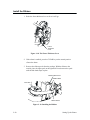
Install the Ribbon
1. Raise the forms thickness lever as far as it will go.
Forms
Thickness
Lever
Figure 2–18. The Forms Thickness Lever
2. If the alarm is enabled, press the CLEAR key on the control panel to
silence the alarm.
3. Remove the ribbon spools from the package. With the ribbon to the
outside, place the right spool on the right hub. Press down on the spool
until the hub latch snaps in place.
Hammer Bank Cover
Ribbon Mask
Hub Latch
Ribbon Guide
Figure 2–19. Installing the Ribbon
2–20
Setting Up the Printer
4. Refer to Figure 2–19 and to the ribbon path diagram on the shuttle cover,
and thread the ribbon as follows: Starting from the right ribbon spool,
thread the ribbon around the right ribbon guide, under the right tractor
gate, between the hammer bank cover and ribbon mask, and along the
ribbon path to the left ribbon guide.
NOTE: The ribbon must not be twisted. A twisted ribbon can lower print
quality, shorten ribbon life, or cause paper jams.
5. Place the left spool on the left hub. Press down on the spool until the hub
latch snaps into place. Hand-turn the right spool and check to make sure
the ribbon tracks correctly in the path and around the ribbon guides.
6. Lower the forms thickness lever. Set it to match the paper thickness.
NOTE: Do not set the forms thickness lever too tightly; excessive friction
can cause paper jams, smeared ink, or wavy print.
7. Press CLEAR to clear the “Platen Open” fault.
8. Press ONLINE to place the printer on–line.
9. Continue with the next section to test the printer.
Setting Up the Printer
2–21
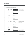
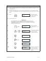
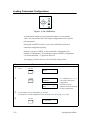
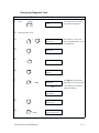
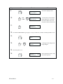
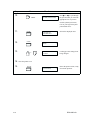
Test the Printer
Step
Press
Result
Notes
1.
The printer should be turned on and loaded with paper and ribbon. The top cover should be raised and
the control panel display should read “Off-Line Ready.”
2.
Press:
ENTER Switch
Not Locked
+
3.
Ribbon Life
4.
Diagnostics
5.
Press both keys at the same time.
Unlocking the ENTER key
allows you to test your printer.
Configuration
Printout
6.
UNTIL
Printer Test
Full Width
OR
Press " until you reach the
appropriate test, for wide paper
(132 columns) or for narrow
paper (80 columns).
Printer Test
8 Inch Width
7.
8.
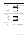
2–22
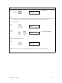
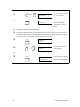
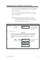
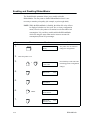
Printer Test
Shift Recycle
To start the
test, press:
ENTER
Running Test
Shift Recycle
Prints shifted lines of the current
character set across the paper
(either 80 or 132 columns).
Setting Up the Printer
Step
Press
Result
Notes
9.
To stop the
test, press:
10.
Examine the print quality of the characters. They should be fully formed and of uniform density. If the
test does not run or if text characters do not appear correctly formed, contact your service
representative.
11.
ENTER
CLEAR
12.
13.
14.
15.
Stops printing.
Printer Test
Shift Recycle
Off–Line
Ready
+
1
Re-locks the ENTER key.
ENTER Switch
Locked
Close the printer top cover.
ON LINE
On–Line
(Current Font)
1
The printer is ready for configuration. Continue with Chapter 3, Configuring the Printer.
Setting Up the Printer
2–23
2–24
Setting Up the Printer
3
Configuring the Printer
Chapter Contents
Overview . . . . . . . . . . . . . . . . . . . . . . . . . . . . . . . . . . . . . . . . . . . . . . . . . . . . . 3–5
Operating States . . . . . . . . . . . . . . . . . . . . . . . . . . . . . . . . . . . . . . . . . . . . 3–7
The Configurations . . . . . . . . . . . . . . . . . . . . . . . . . . . . . . . . . . . . . . . . . . 3–7
Unlocking the ENTER Key . . . . . . . . . . . . . . . . . . . . . . . . . . . . . . . . . . . 3–8
Locking the ENTER Key . . . . . . . . . . . . . . . . . . . . . . . . . . . . . . . . . . . . . 3–8
Saving Parameters . . . . . . . . . . . . . . . . . . . . . . . . . . . . . . . . . . . . . . . . . . 3–9
Factory Default Configuration Values . . . . . . . . . . . . . . . . . . . . . . . . . . . . . . 3–10
Printing the Current Configuration . . . . . . . . . . . . . . . . . . . . . . . . . . . . . . . . . 3–12
Changing Configuration Values . . . . . . . . . . . . . . . . . . . . . . . . . . . . . . . . . . . 3–14
Saving Your New Configuration . . . . . . . . . . . . . . . . . . . . . . . . . . . . . . . . . . 3–17
Loading Predefined Configurations . . . . . . . . . . . . . . . . . . . . . . . . . . . . . . . . 3–19
Loading Customized Configurations . . . . . . . . . . . . . . . . . . . . . . . . . . . . . . . 3–22
Resetting the Printer to Default or Saved Parameters . . . . . . . . . . . . . . . . . . 3–23
Configuration Menu Diagrams . . . . . . . . . . . . . . . . . . . . . . . . . . . . . . . . . . . 3–24
Ribbon Life Menu Options . . . . . . . . . . . . . . . . . . . . . . . . . . . . . . . . . . . . . . . 3–26
New Ribbon . . . . . . . . . . . . . . . . . . . . . . . . . . . . . . . . . . . . . . . . . . . . . . . 3–27
Set Job Rate . . . . . . . . . . . . . . . . . . . . . . . . . . . . . . . . . . . . . . . . . . . . . . . 3–27
Analyze Job . . . . . . . . . . . . . . . . . . . . . . . . . . . . . . . . . . . . . . . . . . . . . . . 3–27
Set Ribbon Size . . . . . . . . . . . . . . . . . . . . . . . . . . . . . . . . . . . . . . . . . . . . 3–27
When Worn Action . . . . . . . . . . . . . . . . . . . . . . . . . . . . . . . . . . . . . . . . . . 3–27
Enable/Disable . . . . . . . . . . . . . . . . . . . . . . . . . . . . . . . . . . . . . . . . . . . . . 3–28
Font Menu Options . . . . . . . . . . . . . . . . . . . . . . . . . . . . . . . . . . . . . . . . . . . . . 3–28
Character Set Menu Options . . . . . . . . . . . . . . . . . . . . . . . . . . . . . . . . . . . . . . 3–30
Application Compatibility Menu Options . . . . . . . . . . . . . . . . . . . . . . . . . . . 3–32
Printer Protocol . . . . . . . . . . . . . . . . . . . . . . . . . . . . . . . . . . . . . . . . . . . . 3–34
Configuring the Printer
3–1
Buffer Size . . . . . . . . . . . . . . . . . . . . . . . . . . . . . . . . . . . . . . . . . . . . . . . . 3–34
Uppercase Select . . . . . . . . . . . . . . . . . . . . . . . . . . . . . . . . . . . . . . . . . . . 3–35
Printer Select . . . . . . . . . . . . . . . . . . . . . . . . . . . . . . . . . . . . . . . . . . . . . . 3–35
Paper Advance SW (Switch) . . . . . . . . . . . . . . . . . . . . . . . . . . . . . . . . . . 3–36
Power On State . . . . . . . . . . . . . . . . . . . . . . . . . . . . . . . . . . . . . . . . . . . . . 3–36
Alarm On Fault . . . . . . . . . . . . . . . . . . . . . . . . . . . . . . . . . . . . . . . . . . . . 3–37
Shuttle Timeout . . . . . . . . . . . . . . . . . . . . . . . . . . . . . . . . . . . . . . . . . . . . 3–37
Unidirectional . . . . . . . . . . . . . . . . . . . . . . . . . . . . . . . . . . . . . . . . . . . . . . 3–37
Select SFCC . . . . . . . . . . . . . . . . . . . . . . . . . . . . . . . . . . . . . . . . . . . . . . . 3–38
80–9F Hex . . . . . . . . . . . . . . . . . . . . . . . . . . . . . . . . . . . . . . . . . . . . . . . . 3–38
Control Code 06 . . . . . . . . . . . . . . . . . . . . . . . . . . . . . . . . . . . . . . . . . . . . 3–38
Control Code 08 . . . . . . . . . . . . . . . . . . . . . . . . . . . . . . . . . . . . . . . . . . . . 3–39
Overstrike . . . . . . . . . . . . . . . . . . . . . . . . . . . . . . . . . . . . . . . . . . . . . . . . . 3–39
Compress Print . . . . . . . . . . . . . . . . . . . . . . . . . . . . . . . . . . . . . . . . . . . . . 3–40
Draft Print . . . . . . . . . . . . . . . . . . . . . . . . . . . . . . . . . . . . . . . . . . . . . . . . . 3–40
Font Select/Elongated . . . . . . . . . . . . . . . . . . . . . . . . . . . . . . . . . . . . . . . 3–41
View . . . . . . . . . . . . . . . . . . . . . . . . . . . . . . . . . . . . . . . . . . . . . . . . . . . . . 3–41
Display Language . . . . . . . . . . . . . . . . . . . . . . . . . . . . . . . . . . . . . . . . . . . 3–41
Paper Format Menu Options . . . . . . . . . . . . . . . . . . . . . . . . . . . . . . . . . . . . . . 3–42
Line Spacing . . . . . . . . . . . . . . . . . . . . . . . . . . . . . . . . . . . . . . . . . . . . . . . 3–43
Form Length Set . . . . . . . . . . . . . . . . . . . . . . . . . . . . . . . . . . . . . . . . . . . . 3–43
Auto Line Feed . . . . . . . . . . . . . . . . . . . . . . . . . . . . . . . . . . . . . . . . . . . . . 3–44
Define CR (Carriage Return) Code . . . . . . . . . . . . . . . . . . . . . . . . . . . . . 3–44
Define LF (Line Feed) Code . . . . . . . . . . . . . . . . . . . . . . . . . . . . . . . . . . 3–44
VFU (Vertical Format Unit) Select . . . . . . . . . . . . . . . . . . . . . . . . . . . . . 3–45
VFU (Vertical Format Unit) Table . . . . . . . . . . . . . . . . . . . . . . . . . . . . . . 3–46
Perforation Skip . . . . . . . . . . . . . . . . . . . . . . . . . . . . . . . . . . . . . . . . . . . . 3–46
Paper Out . . . . . . . . . . . . . . . . . . . . . . . . . . . . . . . . . . . . . . . . . . . . . . . . . 3–46
Paperout Adjust . . . . . . . . . . . . . . . . . . . . . . . . . . . . . . . . . . . . . . . . . . . . 3–47
PMD (Paper Motion Detection) Fault . . . . . . . . . . . . . . . . . . . . . . . . . . . 3–47
Slew Relative . . . . . . . . . . . . . . . . . . . . . . . . . . . . . . . . . . . . . . . . . . . . . . 3–48
Set Platen @ BOF . . . . . . . . . . . . . . . . . . . . . . . . . . . . . . . . . . . . . . . . . . 3–48
Print Width . . . . . . . . . . . . . . . . . . . . . . . . . . . . . . . . . . . . . . . . . . . . . . . . 3–48
3–2
Configuring the Printer
Slow Paper Slew . . . . . . . . . . . . . . . . . . . . . . . . . . . . . . . . . . . . . . . . . . . 3–49
Host Interface Menu Options . . . . . . . . . . . . . . . . . . . . . . . . . . . . . . . . . . . . . 3–50
Centronics Menu Options . . . . . . . . . . . . . . . . . . . . . . . . . . . . . . . . . . . . . . . . 3–51
Data Bit 8 . . . . . . . . . . . . . . . . . . . . . . . . . . . . . . . . . . . . . . . . . . . . . . . . . 3–52
PI (Paper Instruction) Line . . . . . . . . . . . . . . . . . . . . . . . . . . . . . . . . . . . . 3–52
Data Polarity . . . . . . . . . . . . . . . . . . . . . . . . . . . . . . . . . . . . . . . . . . . . . . . 3–53
Response Polarity . . . . . . . . . . . . . . . . . . . . . . . . . . . . . . . . . . . . . . . . . . . 3–53
Fast Busy . . . . . . . . . . . . . . . . . . . . . . . . . . . . . . . . . . . . . . . . . . . . . . . . . 3–53
Strobe Polarity . . . . . . . . . . . . . . . . . . . . . . . . . . . . . . . . . . . . . . . . . . . . . 3–54
Latch Data On . . . . . . . . . . . . . . . . . . . . . . . . . . . . . . . . . . . . . . . . . . . . . 3–54
Dataproducts Menu Options . . . . . . . . . . . . . . . . . . . . . . . . . . . . . . . . . . . . . . 3–55
Data Bit 8 . . . . . . . . . . . . . . . . . . . . . . . . . . . . . . . . . . . . . . . . . . . . . . . . . 3–56
PI (Paper Instruction) Line . . . . . . . . . . . . . . . . . . . . . . . . . . . . . . . . . . . . 3–56
Data Polarity . . . . . . . . . . . . . . . . . . . . . . . . . . . . . . . . . . . . . . . . . . . . . . . 3–56
Response Polarity . . . . . . . . . . . . . . . . . . . . . . . . . . . . . . . . . . . . . . . . . . . 3–57
Strobe Polarity . . . . . . . . . . . . . . . . . . . . . . . . . . . . . . . . . . . . . . . . . . . . . 3–57
Latch Data On . . . . . . . . . . . . . . . . . . . . . . . . . . . . . . . . . . . . . . . . . . . . . 3–57
Serial RS-232 Menu Options . . . . . . . . . . . . . . . . . . . . . . . . . . . . . . . . . . . . . 3–58
Data Protocol . . . . . . . . . . . . . . . . . . . . . . . . . . . . . . . . . . . . . . . . . . . . . . 3–59
Data Rate . . . . . . . . . . . . . . . . . . . . . . . . . . . . . . . . . . . . . . . . . . . . . . . . . 3–59
Word Length . . . . . . . . . . . . . . . . . . . . . . . . . . . . . . . . . . . . . . . . . . . . . . . 3–59
Stop Bit . . . . . . . . . . . . . . . . . . . . . . . . . . . . . . . . . . . . . . . . . . . . . . . . . . . 3–60
Parity . . . . . . . . . . . . . . . . . . . . . . . . . . . . . . . . . . . . . . . . . . . . . . . . . . . . 3–60
Bit 8 Function . . . . . . . . . . . . . . . . . . . . . . . . . . . . . . . . . . . . . . . . . . . . . . 3–60
Data Term Ready . . . . . . . . . . . . . . . . . . . . . . . . . . . . . . . . . . . . . . . . . . . 3–61
Request to Send . . . . . . . . . . . . . . . . . . . . . . . . . . . . . . . . . . . . . . . . . . . . 3–61
Reverse Channel . . . . . . . . . . . . . . . . . . . . . . . . . . . . . . . . . . . . . . . . . . . . 3–62
Load Parameters Menu Options . . . . . . . . . . . . . . . . . . . . . . . . . . . . . . . . . . . 3–63
Load Saved Parameters (1, 2, 3, or 4) . . . . . . . . . . . . . . . . . . . . . . . . . . . 3–64
Load IGP Parameters . . . . . . . . . . . . . . . . . . . . . . . . . . . . . . . . . . . . . . . . 3–64
Load IBM 3287 Parameters . . . . . . . . . . . . . . . . . . . . . . . . . . . . . . . . . . . 3–64
Load IBM 5225 Parameters . . . . . . . . . . . . . . . . . . . . . . . . . . . . . . . . . . . 3–64
Configuring the Printer
3–3
Load Factory Parameters . . . . . . . . . . . . . . . . . . . . . . . . . . . . . . . . . . . . . 3–65
Save Parameters Menu Options . . . . . . . . . . . . . . . . . . . . . . . . . . . . . . . . . . . 3–66
Diagnostics Menu Options . . . . . . . . . . . . . . . . . . . . . . . . . . . . . . . . . . . . . . . 3–67
3–4
Configuring the Printer
Overview
IMPORTANT
Configuration directly affects printer operation. Do not change the
configuration of your printer until you are thoroughly familiar with the
procedures in this chapter.
In order to print data, the printer must respond correctly to signals and
commands received from the host computer. Configuration is the process of
matching the printer’s operating characteristics to those of the host computer.
The characteristics that define the printer’s response to signals and
commands received from the host computer are called configuration
parameters.
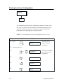
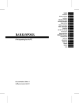
You can configure the printer by pressing keys on the control panel or by
sending control codes in the data stream from the host computer.
This chapter shows you how to configure the printer by using the control
panel, which is shown below.
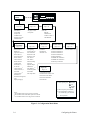
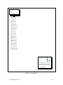
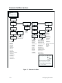
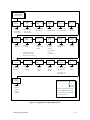
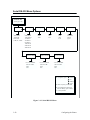
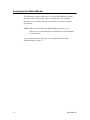
Figure 3–2 shows the top level of the configuration menu. (All of the keys on
the control panel are described in detail in your Operator’s Guide.)
To configure the printer with control codes, refer to the Programmer’s
Reference Manual.
VIEW
UP
SET TOF
PREV
NEXT
CONFIG
DOWN
Off–Line
Ready
1
ON LINE
FF
NLQ
CLEAR
ENTER
Figure 3–1. The Control Panel
Configuring the Printer
3–5
Off–Line
Ready
Ribbon Life
Page 3–26
New Ribbon
Set Job Rate
Analyze Job
Set Ribbon Size
When Worn Action
Enable/Disable
Application
Compatibility
Page 3–33
Printer Protocol
Buffer Size
Uppercase Select 1,2
Printer Select 1,3
Paper Advance Sw
Power On State
Alarm On Fault
Shuttle Timeout
Unidirectional
Select SFCC 2,3
80–9F Hex
Control Code 06 2
Control Code 08 2,3
Overstrike
Compress Print 1,2
Draft Print 1,2
Font Select Elongated 1,2
View
Display Language
Font
Character Set
Page 3–29
Page 3–30
See page 3–29 for
font options.
Select Set
IBM PC
Multinational
ECMA–94 Latin 1
DEC Multinat.
Paper Format
Host Interface
Load Parameters
Save Parameters
Page 3–42
Page 3–50
Page 3–63
Page 3–66
Line Spacing
Form Length Set
Auto Line Feed
Define CR Code
Define LF Code
VFU Select 2
VFU Table 2
Perforation Skip
Paper Out
Paperout Adjust
PMD Fault
Slew Relative 1,2
Set Platen @BOF
Print Width
Slow Paper Slew
Centronics
Dataproducts
Serial RS–232
Load Saved Parameters 1
Press ENTER to save
Load Saved Parameters 2
Load Saved Parameters 3
Load Saved Parameters 4
Load IGP Parameters
Load IBM 3287 Parameters
Load IBM 5225 Parameters
Load Factory Parameters
Diagnostics
Page 3–67
Configuration Printout
Print Datastream in Hex Code
Printer Test 8 Inch Width
Printer Test Full Width
Print Statistics
To view options, press: B DOWN
Y UP
" RIGHT
A LEFT
To select an option, press ENTER
Notes:
1 Not available when P–Series protocol is selected.
2 Not available when Serial Matrix protocol is selected.
3 Not available when P–Series XQ protocol is selected.
To exit configuration (returning to
Off–Line Ready), press CLEAR
*
= Factory Default
Figure 3–2. Configuration Main Menu
3–6
Configuring the Printer
Operating States
The printer has two operating states: on-line and off-line. When the printer is
on-line, it is controlled by the host computer and prints data sent by the host
computer. In the off-line state, communication with the host is interrupted so
that you can load paper, change ribbons, or test and configure the printer.
NOTE: When the printer is on-line, it may display an “L” in the lower right
corner of the message display, or an “E” in the upper right corner.
See page 3–45 for information on the VFU Select parameter.
The Configurations
A configuration consists of a group of parameters, such as line spacing,
forms length, etc. Your printer contains the following configurations:
•
The factory default configuration. It can be loaded, but it cannot be
altered. Table 3–1 on page 3–10 lists all of the parameters and their
values.
•
IGP, IBM 3287, and IBM 5225. Any one of the three can be loaded, but
not altered. Appendix D lists all of the parameters and their values.
•
Four configurations that you can customize for unique print job
requirements. Page 3–14 explains how to create customized
configurations.
Configuring the Printer
3–7
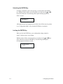
Unlocking the ENTER Key
To change a parameter, such as line spacing, you must unlock the ENTER
key. With the printer off-line, raise the printer cover and press the Y and B
keys at the same time. The following control panel message appears for
about a second:
ENTER Switch
Not Locked
Although all menus and settings are accessible in the off-line state, the printer
is in “Configuration Mode” only when the ENTER key is unlocked.
Locking the ENTER Key
When you lock the ENTER key, your configuration settings cannot be
altered. Locking secures your settings.
With the printer off-line, raise the printer cover and press the Y and B keys
at the same time to lock the ENTER key. The following control panel
message appears for about a second:
ENTER Switch
Locked
3–8
Configuring the Printer
Saving Parameters
You can change a parameter, such as line spacing or form length, by pressing
keys on the control panel or by sending control codes from the host data
stream. Your programming reference manual provides information about
control codes.
Once you change a parameter, it is active as long as the printer is on. This is
true whether you use the control panel or send a control code from the host.
If you use the control panel, you can save the parameters as a customized
configuration that is stored in non-volatile random access memory
(NVRAM). A configuration consists of a group of parameters. The
configuration will not be lost if you turn off the printer.
There are no control codes that allow you to save a parameter in NVRAM.
However, control codes override control panel parameters. For example, if
you set the line spacing to 6 lines per inch (LPI) with the control panel, and
application software later changes this to 8 LPI with a data stream command,
the data stream setting overrides the control panel setting.
The 8 LPI parameter is effective as long as the printer is on. If you turn off
the printer, the 8 LPI parameter will be erased. To save the parameter, you
must use the control panel and save it as a configuration.
Configuring the Printer
3–9
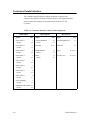
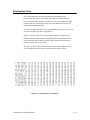
Factory Default Configuration Values
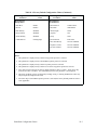
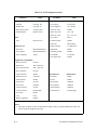
The printer is configured at the factory as shown in Table 3–1. All of the
values are permanently stored in ROM and are easily reloaded. To load the
factory default values, use the Load Parameters menu (page 3–19), or reset
the printer (page 3–23) if the Factory Default is the designated power–up.
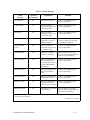
Table 3–1. Factory Default Configuration Values
Configuration
Parameter
Factory Default
Value
Ribbon Life
Configuration
Parameter
Factory Default
Value
Application Compatibility (Continued)
Job Rate
Currently 150
Font Select /
Elongated1
Font Select = 0E
Elongated = 08
Ribbon Size
Currently 60
View
Lines
When Worn Action
To Stop Printer
Display Language
English
Enable/Disable
Disable Action
Paper Format
Font
Font
DP AT 10 CPI
Character Set
Select Set
IBM PC
Line Spacing
Set at 6 LPI
Form Length Set
At 11 Inches
Auto Line Feed
After Full Line
Define CR Code
CR = CR
Define LF Code
LF = CR + LF
Select4
EVFU5
Select Subset
IBM PC GRAPHICS
VFU
Select Language
ASCII
Perforation Skip
Disable
Paper Out
End of Paper
Paperout Adjust
113 Dot Rows6
PMD Fault
Enable
Application Compatibility
Printer Protocol
Buffer Size
P-Series
Relative1
2048 Characters
Slew
Upper & Lower
Set Platen @ BOF
Disable
Disable
Print Width
13.2 Inches
Paper Advance SW
Print + Pap Adv
Slow Paper Slew
Disable
Power On State
On-Line
Alarm On Fault
Enable
Shuttle Timeout
4 Seconds
Data Bit 8
Enable
Unidirectional
Disable
PI Line
Disable7
Select SFCC3
01 SOH
Data Polarity
Standard
80–9F Hex.
Control Codes
Resp. Polarity
Standard
Uppercase
Printer
3–10
Select1
Select2
Host Interface
1 to 16
Centronics
Configuring the Printer
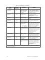
Table 3–1. Factory Default Configuration Values (Continued)
Configuration
Parameter
Factory Default
Value
Application Compatibility
Control Code 064
Control Code
083
Overstrike
Compress
Print1
Draft Print1
Configuration
Parameter
Factory Default
Value
Host Interface
Centronics
8.0 LPI
Fast Busy
Enable
Double High
Strobe Polarity
Standard
Enable
Latch Data On
Leading Edge
01 SOH
02 STX
Host Interface
Dataproducts
Host Interface
Serial RS-232
Data Bit 8
Enable
Data Protocol
X-ON/X-OFF
PI Line
Enable7
Data Rate
9600 BAUD
Data Polarity
Standard
Word Length
8 Bits
Resp. Polarity
Standard
Stop Bit
One
Strobe Polarity
Standard
Parity
None
Latch Data On
Leading Edge
Bit 8 Function
Font Select
Data Term Ready
On-Line and BNF
Request To Send
On-Line and BNF
Reverse Channel
On-Line and BNF
Notes:
1. This parameter is displayed only if P-Series XQ printer protocol is selected.
2. This parameter is displayed only if Serial Matrix printer protocol is selected.
3. This parameter is displayed only if P-Series printer protocol is selected.
4. This parameter is displayed only if P-Series or P-Series XQ printer protocol is selected.
5. For P-Series printer protocol, the factory default parameter value is “EVFU”. For P-Series XQ
protocol, the value is “Enable”. For Serial Matrix protocol, the parameter is not displayed.
6. The paper out adjust value is not affected by loading, saving, or clearing NVRAM. Its value may
only be explicitly changed in the menu.
7. If P-Series XQ or Serial Matrix printer protocol is selected, the factory default parameter value is
“Not Applicable”.
Configuring the Printer
3–11
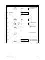
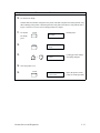
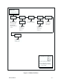
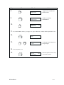
Printing the Current Configuration
Diagnostics
Configuration
Printout
The configuration printout lists the configuration parameters currently stored
and in use. The printout lists the main menus and submenu parameters in the
same order as they occur when you use the control panel to configure the
printer. Refer to the following steps to obtain a printout.
NOTE: It is recommended you print your configuration after you save it.
Step
1.
2.
3.
Press
Press:
ON LINE
Result
Off–Line
Ready
+
ENTER Switch
Not Locked
Ribbon Life
5.
Diagnostics
3–12
1
The printer must be
off-line to print the
configuration.
Raise the printer cover.
4.
6.
Notes
Unlocking the ENTER key
allows you to print the
configuration.
Configuration
Printout
Configuring the Printer
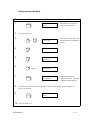
Step
Press
7.
8.
ENTER
10.
12.
Off–Line
Ready
+
1
Prevents settings from
being changed.
ENTER Switch
Locked
FF
Advances the paper.
Carefully tear off the configuration printout.
13.
14.
The configuration listing
begins printing.
Configuration
Printout
CLEAR
11.
Notes
Configuration
Printing
Wait until the
printer stops
printing.
9.
Result
FF
Advances the paper.
Close the printer cover. Store the printout in a safe place; write the date and other identifiable
information on the printout.
15.
Configuring the Printer
ON LINE
On–Line
(Current Font)
1
Places the printer on-line,
ready for normal operation.
3–13
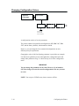
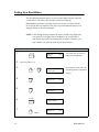
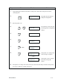
Changing Configuration Values
Application
Compatibility
Paper Format
Line Spacing
Form Length Set
Auto Line Feed
Set at 6 LPI
Set at 8 LPI
Set at 10.3 LPI
A configuration consists of several parameters.
The printer contains four predefined configurations (IGP, IBM 3287, IBM
5225, and the factory default), which cannot be altered.
However, you can change the four customized configurations to meet
different print job requirements.
Changing the value of the Line Spacing parameter is provided as an example.
Use these basic guidelines to move throughout the configuration menu and
change other parameters. Page 3–6 shows the top level of the configuration
menu.
IMPORTANT
You can change the parameters at any time. However, if you intend to
SAVE the changes, be sure the current configuration is the one you want
to revise.
NOTE: You can press CLEAR at any time to return to off-line.
3–14
Configuring the Printer
Step
Press
Result
Notes
1.
Make a configuration printout. Refer to “Printing the Current Configuration” on page 3–12. You
may skip this step.
2.
Determine which parameters you want to change, and what their new values should be. (In this
example, we are changing the value of the Line Spacing parameter from “Set at 6 LPI” to “Set at 8
LPI”.)
3.
Press:
4.
ON LINE
Off–Line
Ready
1
The printer must be
off-line to change the
configuration.
Raise the printer cover.
IMPORTANT
If you intend to save your changes, they will be saved into the current
configuration. To ensure you have the correct Configuration selected and
loaded, do the following step.
5.
CONFIG
UNTIL
6.
+
7.
UNTIL
10.
Configuring the Printer
ENTER Switch
Not Locked
Selects and loads X
(Configuration 1, 2, 3, or
4).
Unlocking the ENTER key
allows you to make
configuration changes.
Ribbon Life
8.
9.
Load Saved
Completed X
Paper Format
Line Spacing
Line Spacing
Set at 6 LPI *
Asterisk (*) indicates this
is the current setting.
(6 LPI is also the factory
default.)
3–15
Step
Press
11.
12.
OR
ENTER
Result
Notes
Cycle through the values
(6, 8, or 10.3 LPI).
Line Spacing
Set at X LPI *
Selects the displayed value.
Asterisk (*) appears,
indicating this value is
active.
Line Spacing
Set at 8 LPI *
13.
Continue this pattern to make other changes.
14.
All changes remain in memory until you turn the printer off. If you want to save these changes as a
configuration that is stored in memory and can later be loaded, go to page NO TAG. If you want to
use—but not save—these settings, continue with the following steps.
15.
CLEAR
16.
17.
18.
3–16
Off–Line
Ready
+
1
Prevents settings from
being changed.
ENTER Switch
Locked
Close the printer cover.
ON LINE
On–Line
(Current Font)
1
Places the printer on-line,
ready for normal operation.
Configuring the Printer
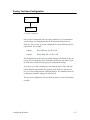
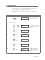
Saving Your New Configuration
Save Parameters
X
Save Parameters
Values Saved
X = Current Configuration
Once you have changed all of the necessary parameters, it is recommended
you save them as a configuration that can be stored and loaded later for
future use. You can save up to four configurations to meet different print job
requirements. For example:
Config 1:
Selects DP font, 10 CPI, 6 LPI
Config 2:
Selects NLQ font, 12 CPI, 8 LPI
The configurations are stored in non-volatile memory (NVRAM), so they are
not lost if you turn off the printer. NVRAM is divided into four blocks, each
of which stores a different setup (group of configuration settings).
If you know you will be printing up to four different types of jobs and each
job has different requirements (line spacing, pitch, form size, character set,
etc.), save each configuration as a different number. This eliminates the need
to change the parameter settings for each new job.
The last saved configuration will load when the printer is turned off and then
on again.
Configuring the Printer
3–17
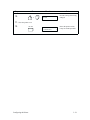
Step
1.
Press
Ribbon Life
3.
UNTIL
4.
ENTER
5.
CLEAR
9.
3–18
X = the current
configuration.
Save Parameters
X
Displays for about one
second. The printer has
stored the new parameters
in NVRAM as power-up
default values.
Save Parameters
Values Saved
Off–Line
Ready
X
X = the current
configuration.
To make a printout of your configuration, go to page 3–12, step 4. If you decide not to print the
configuration, then continue with the following steps.
7.
8.
Notes
Verify you have made all of the necessary changes to your current configuration. Return to the
top of the menu.
2.
6.
Result
+
Prevents settings from
being changed.
ENTER Switch
Locked
Close the printer cover.
ON LINE
On–Line
(Current Font)
X
Places the printer on-line,
ready for normal operation.
Configuring the Printer
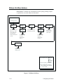
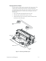
Loading Predefined Configurations
Load Parameters
Load Saved
Parameters 1
Load IGP
Parameters
Load IBM 3287
Parameters
Load IBM 5225
Parameters
Load Factory
Parameters
Use this procedure to load the factory, IGP, IBM 3287, or IBM 5225
configurations. These configurations are stored on ROM and cannot be
altered. See Appendix D.
Although you can use this procedure to load one of the customized
configurations, it is recommended you use the CONFIG key (page 3–22). It
selects and loads a configuration––this configuration is the one that will be
overwritten whenever you save a new setting.
When you load a configuration, it loads all of the stored parameters into the
current configuration. For example, Configuration 1 is selected and loaded
and “1” appears on the LCD. If you load configuration 4 using the menu and
not the CONFIG key, all of its values are temporarily active, but
configuration 4 is not selected. If you change a value and then save it,
Configuration 1 is changed because it is the one that is selected.
To change the current configuration from 1 to 4 and modify 4, you must use
the CONFIG key.
NOTE: The last saved configuration values will load when the printer is
turned off and then on again.
Configuring the Printer
3–19
Step
1.
2.
Press
Press:
ON LINE
Off–Line
Ready
Notes
The printer must be off-line
to load a configuration.
1
Raise the printer cover.
3.
+
4.
Unlocking the ENTER key
allows you to load a
configuration.
ENTER Switch
Not Locked
Ribbon Life
5.
UNTIL
6.
Load Parameters
First of series.
Load Saved
Parameters 1
7.
UNTIL
8.
Result
ENTER
Press the key until you reach
the appropriate parameter set
(IGP, IBM 3287, IBM 5225,
or Factory).
Load Factory
Parameters
Displays for about one
second (message varies,
depending on the parameter
set you are loading). The
printer loads the requested
parameters.
Load Factory
Completed
IMPORTANT
Factory parameters are loaded only into Configuration 1, not saved. If you turn
the printer off and then on, the saved Configuration 1 values will be restored.
9.
3–20
CLEAR
Off–Line
Ready
1
Configuring the Printer
Step
Press
10.
11.
+
Result
Notes
ENTER Switch
Locked
Prevents settings from being
changed.
On–Line
(Current Font)
Places the printer on-line,
ready for normal operation.
Close the printer cover.
12.
Configuring the Printer
ON LINE
1
3–21
Loading Customized Configurations
CONFIG
Figure 3–3. The CONFIG Key
A configuration contains a group of parameters that are set to particular
values. You can customize up to four unique configurations to meet specific
job requirements.
Pressing the CONFIG key allows you to select and load one of the four
customized configurations quickly.
Each time you press CONFIG, it selects and loads a configuration. For
example, if Configuration 1 is loaded and you press CONFIG, Configuration
2 is selected and loads. “2” appears on the LCD.
Any changes you make and save will override the existing values.
Step
1.
2.
Press
Press:
ON LINE
CONFIG
Result
Off–Line
Ready
4.
3–22
1
X = Configuration 1, 2, 3, or
4. It becomes the current
configuration.
Each time you press
CONFIG, it selects and loads
the next configuration.
Load Saved
Completed
Off–Line
Ready
3.
Notes
X
If you intend to use the configuration, go to step 4.
If you plan to revise the configuration, raise the printer cover. Go to page 3–15, step 6.
ON LINE
On–Line
(Current Font)
1
Configuring the Printer
Resetting the Printer to Default or Saved Parameters
Printer reset is also called initializing the printer. This procedure clears RAM
and loads either the factory configuration parameters or a set of parameters
you have saved previously.
Factory parameters are permanently stored in ROM. However, if you have
saved a set of configuration parameters, your most recently saved set loads
when you reset the printer.
NOTE: You can reset the printer any time the power is on: While it is
on-line, off-line, even while it is printing. However, to prevent
losing data, reset the printer only when it is off-line and the printer’s
internal input buffer does not contain data.
Step
1.
2.
Press
Press:
Result
ON LINE
Off–Line
Ready
Notes
Takes the printer off-line.
This step can be skipped,
but doing so might cause
loss of data.
1
Raise the printer cover.
IMPORTANT
In the next step, make sure you press and release CLEAR and ENTER together.
If you hold down the CLEAR key after pressing both keys, NVRAM is erased
(including print statistics) and all printer parameters are reset to the factory
defaults.
3.
CLEAR
ENTER
+
Press and release CLEAR
and ENTER
simultaneously.
Printer Reset
DIAGNOSTIC TEST
IN PROGRESS
X
On–Line
(Current Font)
4.
1
Close the printer cover.
Configuring the Printer
3–23
Configuration Menu Diagrams
The Configuration Menu diagrams on the following pages show the structure
of the configuration menus and the parameters available in each menu. The
diagrams list the menus and options in the order they appear on the control
panel.
NOTE: In the following descriptions, hexadecimal (hex) values are shown
for some ASCII codes, such as command delimiters. To verify your
host computer is sending the correct delimiters or other codes to the
printer, generate a hex code printout and look for the hex value of
the delimiter in the printout. For details, see “Printing Hex Code” on
page 5–13.
3–24
Configuring the Printer
Off–Line
Ready
Ribbon Life
Font
Page 3–29
Page 3–26
New Ribbon
Set Job Rate
Analyze Job
Set Ribbon Size
When Worn Action
Enable/Disable
Application
Compatibility
Page 3–33
Printer Protocol
Buffer Size
Uppercase Select
Printer Select
Paper Advance Sw
Power On State
Alarm On Fault
Shuttle Timeout
Unidirectional
Select SFCC
80–9F Hex
Control Code 06
Control Code 08
Overstrike
Compress Print
Draft Print
Font Select Elongated
View
Display Language
See page 3–29 for
font options.
Character Set
Page 3–30
Select Set
IBM PC
Multinational
ECMA–94 Latin 1
DEC Multinat.
Paper Format
Host Interface
Load Parameters
Save Parameters
Page 3–42
Page 3–50
Page 3–63
Page 3–66
Line Spacing
Form Length Set
Auto Line Feed
Define CR Code
Define LF Code
VFU Select
VFU Table
Perforation Skip
Paper Out
Paperout Adjust
PMD Fault
Slew Relative
Set Platen @BOF
Print Width
Slow Paper Slew
Centronics
Dataproducts
Serial RS–232
Load Saved Parameters 1
Press ENTER to save
Load Saved Parameters 2
Load Saved Parameters 3
Load Saved Parameters 4
Load IGP Parameters
Load IBM 3287 Parameters
Load IBM 5225 Parameters
Load Factory Parameters
Diagnostics
Page 3–67
Configuration Printout
Print Datastream in Hex Code
Printer Test 8 Inch Width
Printer Test Full Width
Print Statistics
To view options, press: B DOWN
Y UP
" RIGHT
A LEFT
To select an option, press ENTER
To exit configuration (returning to
Off–Line Ready), press CLEAR
*
= Factory Default
Figure 3–4. Configuration Main Menu
Configuring the Printer
3–25
Ribbon Life Menu Options
RibbonMinder monitors ink consumption to ensure quality printing. Chapter
6 explains how to use this feature in more detail.
Ribbon Life
(From page 3–25)
New
Ribbon
Analyze
Job
Set
Job Rate
Press ENTER to reset
ribbon life to 100%.
A new ribbon must
be installed after
setting the ribbon life
to 100%.
Currently xxx
New Rate yyy
Press " or A to
increase or
decrease New
Rate by 1
Press ENTER to enter
the Analyze Job mode.
Set
Ribbon Size
When
Worn Action
Currently xxx
New Size yyy
* To Stop Printer
Aud/Vis Alarm
Visual Alarm
Press " or A to
increase or
decrease New
Size by 10
Enable/Disable
*
Disable Action
Enable Action
To view options, press: B DOWN
Y UP
" RIGHT
A LEFT
To select an option, press ENTER
To exit configuration (returning to
Off–Line Ready), press CLEAR
*
= Factory Default
Figure 3–5. Ribbon Life Menu
3–26
Configuring the Printer
New Ribbon
Whenever you install a new ribbon, you must reset the ribbon life to 100%.
Set Job Rate
The job rate describes the rate at which a particular print job wears out the
ribbon. Values can range from 0 (no wear) to 1000 (the highest possible rate
of ink usage). The factory default setting is 150. You can change job rates
without affecting print quality.
Press " and A to select the new job rate, then press ENTER to make the
change effective.
Analyze Job
The “Analyze Job” mode allows you to analyze a print job to determine its
job rate. The job rate describes the rate at which a particular print job wears
out the ribbon.
Press the ENTER key to enter the “Analyze Job” mode. To clear the
“Analyze Job” mode, set the job rate.
Set Ribbon Size
The standard ribbon size is 60 yards long; this is the factory default setting.
You can specify the length in increments of 10 yards. Press " and A to
select the new ribbon size, then press ENTER to make the change effective.
When Worn Action
When RibbonMinder detects zero percentage of ink left on the ribbon, you
can set it to do one of the following:
•
Stop the printer (and enable a visual and/or audible alarm).
•
Initiate a visual and audible alarm that causes the printer to beep and
flash its status lights, but the printer continues to print.
•
Initiate a visual-only alarm that causes the printer to flash its status
lights, but the printer continues to print.
Configuring the Printer
3–27
Enable/Disable
Turns RibbonMinder on or off. Even with RibbonMinder off, the printer
continues to calculate ink consumption. It is possible to enable and disable
RibbonMinder while still on the same ribbon and to retain to accurate ink
consumption (ribbon life) percentages.
Font Menu Options
The printer is capable of printing the following fonts:
•
DP:
Data Processing; medium print resolution.
•
NLQ:
Near Letter Quality (correspondence); high print
resolution.
•
HS:
High Speed; low print resolution. Three speeds
are available: High Speed Draft A (HS), High
Speed Draft B (HSB), and High Speed Draft C
(HSC).
•
OCR-A:
Optical Character Recognition Font A; print
quality suitable for optical character readers.
•
OCR-B:
Optical Character Recognition Font B; print
quality suitable for optical character readers.
Pitch is the number of text characters printed per horizontal inch. It is
specified in characters per inch (cpi). Most of the fonts in the printer have
several pitch choices; the available choices are shown in Figure 3–6 on page
3–29.
As examples, selecting “HSC AT 12 CPI” sets up the printer to print at 12
characters per inch in the High Speed Draft C mode, while selecting “NLQ
AT 10 CPI” sets up the printer to print at 10 characters per inch in the Near
Letter Quality mode.
See page A–7 for horizontal and vertical dot densities.
3–28
Configuring the Printer
Font
(From page 3–25)
* DP AT 10 CPI
DP AT 12 CPI
DP AT 13 CPI
DP AT 15 CPI
DP AT 17 CPI
DP AT 20 CPI
NLQ AT 10 CPI
NLQ AT 12 CPI
NLQ AT 12.9 CPI
NLQ AT 15 CPI
NLQ AT 16.4 CPI
HS AT 10 CPI
HS AT 12 CPI
HS AT 13 CPI
HS AT 15 CPI
HS AT 17 CPI
HSB AT 10 CPI
HSB AT 12 CPI
HSB AT 13 CPI
HSB AT 15 CPI
HSB AT 17 CPI
HSC AT 10 CPI
HSC AT 12 CPI
HSC AT 13 CPI
HSC AT 15 CPI
HSC AT 17 CPI
OCR–A AT 10 CPI
OCR–B AT 10 CPI
To view options, press: B DOWN
Y UP
" RIGHT
A LEFT
To select an option, press ENTER
To exit configuration (returning to
Off–Line Ready), press CLEAR
*
= Factory Default
Figure 3–6. Font Menu
Configuring the Printer
3–29
Character Set Menu Options
Character
Set
(From page 3–25)
Select
Set
MULTINATIONAL
IBM PC
Select
Subset
Primary
Select
Language
Extended
*
FRENCH
GERMAN
ENGLISH
DANISH
SWEDISH
ITALIAN
SPANISH
JAPANESE
FRENCH CANADIAN
LATIN AM
NORWEGIAN
DANISH II
SPANISH II
LATIN AM II
Select
Language
Select
Subset
* ASCII
Primary
DEC
MULTINAT.
Select
Language
Extended
EBCDIC
IBM PC GRAPHICS
CODE PAGE 850
* ASCII
ECMA–94
LATIN 1
Select
Language
Select
Language
*ASCII
GERMAN
SWEDISH
DANISH
NORWEGIAN
FINNISH
ENGLISH
DUTCH
FRENCH
SPANISH
ITALIAN
TURKISH
JAPANESE
*
MULTINATIONAL
BAR CODE DP10
MULTINAT. DP10
MULTINAT. DP12
MULTINAT. NLQ10
GREEK DP10
GREEK DP12
GREEK NLQ10
GRAPHICS DP10
GRAPHICS NLQ10
SCIENT. DP10
SCIENT. DP12
SCIENT. NLQ10
*ASCII
FRENCH
GERMAN
ENGLISH
NORW./DAN.
SWEDISH
ITALIAN
SPANISH
JAPANESE
FRENCH CANADIAN
DUTCH
FINNISH
SWISS
To view options, press: B DOWN
Y UP
" RIGHT
A LEFT
To select an option, press ENTER
To exit configuration (returning to
Off–Line Ready), press CLEAR
*
= Factory Default
Figure 3–7. Character Set Menu
3–30
Configuring the Printer
Figure 3–7 shows the Character Set Menu. This menu defines which
character code or symbol set the printer uses, including bar code character
sets.
There are four possible character sets from which to choose: IBM PC,
Multinational, ECMA-94 Latin 1, and DEC Multinational. Each of these
character sets has several additional choices for language. In addition, the
language choices for the IBM PC character set and for the ECMA-94 Latin 1
character set are further subdivided into a primary and an extended subset, as
shown in the figure.
As an example, pressing the B key from the Character Set menu will display
“Select Set IBM PC”. Pressing " twice selects the ECMA-94 Latin 1 set. If
you then press the B key, your choices will be either the “Primary” or
“Extended” subset. If you press " to select “Extended”, followed by the B
key, your choices will be: “Multinational”, “Barcode DP 10”, and so on,
through “Scient. NLQ 10”. Press the " and A keys until the display shows
the choice you want, then press ENTER to select that choice.
Refer to the Programmer’s Reference Manual for character set charts.
NOTE: DOWNLOADED is displayed when a downloaded substitution
table is active.
Configuring the Printer
3–31
Application Compatibility Menu Options
The Application Compatibility parameters, shown in Figure 3–8, control the
overall operation of the printer:
•
Printer Protocol
•
80–9F Hex.
•
Buffer Size
•
Control Code 06
•
Uppercase Select
•
Control Code 08
•
Printer Select
•
Overstrike
•
Paper Advance SW
•
Compress Print
•
Power On State
•
Draft Print
•
Alarm On Fault
•
Font Select / Elongated
•
Shuttle Timeout
•
View
•
Unidirectional
•
Display Language
•
Select SFCC
For definitions of terminology used in this section, refer to the Glossary at
the end of this manual. For more detailed information, refer to the
Programmer’s Reference Manual.
NOTE: In the following descriptions, hexadecimal (hex) values are shown
for some ASCII codes, such as command delimiters. If you want to
verify that your host computer is sending the correct delimiters or
other codes to the printer, you can obtain a hex code printout and
look for the hex value of the delimiter in the printout. For details,
see “Printing Hex Code” on page 5–13.
3–32
Configuring the Printer
Application
Compatibility
(From page 3–25)
Printer
Protocol
Uppercase
Select
* P–Series
Serial Matrix
P–Series XQ
* 2048 Characters
512 Characters
1024 Characters
* Upper & Lower
Alarm On
Fault
Shuttle
Timeout
Unidirectional
* Enable
Disable
Control
Code 08
*
Buffer
Size
Double High
Backspace
* 4 Seconds
10 Seconds
.
.
300 Seconds (Timeouts
range from 10 to 300 in
increments of 5 seconds.)
Uppercase Only
* Disable
P–Series Plot
Enable
Overstrike
Compress
Print
*
*
Enable
Disable
01 SOH
03 ETX
09 HT
Paper
Advance SW
Printer
Select
* Disable
* Print + Pap Adv
On=DC1/Off=DC3
Move Paper Only
Select
SFCC
*
01
03
1B
5E
7E
7E
SOH
ETX
ESC
Circumflex
Tilde
5D Tilde ]
80–9F
Hex.
*
Control Codes
Printable
Draft
Print
*
02 STX
03 ETX
09 HT
Power On
State
* On–Line
Off–Line
Control
Code 06
*
Font Select
Elongated
*
Font Select = 0E
Elongated = 08
8.0 LPI
10.3 LPI
View
*
Lines
Labels
Font Select = 08
Elongated = 0E
Display
Language
*
English
Deutsch
Français
Español
Italiano
To view options, press: B DOWN
Y UP
" RIGHT
A LEFT
To select an option, press ENTER
To exit configuration (returning to
Off–Line Ready), press CLEAR
*
= Factory Default
Figure 3–8. Application Compatibility Menu
Configuring the Printer
3–33
Printer Protocol
The Printer Protocol parameter enables you to set the desired printer
emulation.
•
P-Series:
Standard Printronix P-Series emulation. The
command delimiter is an ASCII code that is
configured from the control panel via the Select
SFCC parameter. (The ASCII Code SOH (01 hex) is
the default command delimiter. See the description
of the Select SFCC parameter on page 3–38.)
•
Serial Matrix:
IBM Graphics Printer emulation; uses ASCII Code
ESC (1B hex) as a command delimiter.
•
P-Series XQ:
Printronix P300 or P600 printer emulation; uses no
command delimiters.
Buffer Size
The Buffer Size parameter allows you to select the number of characters that
the printer internal input buffer can contain, including non-printable
characters. You can change the buffer size, depending on your host
computer’s requirements.
3–34
•
2048 characters
•
512 characters
•
1024 characters
Configuring the Printer
Uppercase Select
The Uppercase Select parameter controls how the printer handles lowercase
characters it receives from the host computer.
•
Upper & Lower:
The printer prints lowercase characters received
from the host computer as lowercase, and uppercase
characters received from the computer as uppercase.
•
Uppercase Only:
The printer prints lowercase characters received
from the host computer as their corresponding
uppercase equivalents; uppercase characters received
from the computer are printed as uppercase.
NOTE: The Uppercase Select parameter is available only when the P-Series
XQ Printer Protocol has been selected.
Printer Select
The Printer Select parameter allows you to use control codes DC1 (on) and
DC3 (off) to cause the printer to interpret or ignore data sent from the host
computer.
•
Disable:
Turns off the Printer Select feature. DC1 and
DC3 control codes have no effect on the printer.
•
On=DC1/Off=DC3:
Turns on the Printer Select feature. When the
printer receives a DC3 control code from the
host computer, the printer discards all host data
following the DC3 until it receives a DC1
control code. When the printer receives a DC1
from the host, the printer processes all host data
following the DC1 until it receives a DC3.
NOTE: The Printer Select parameter is available only when the Serial
Matrix Printer Protocol has been selected.
Configuring the Printer
3–35
Paper Advance SW (Switch)
The Paper Advance SW parameter controls the action of the Form Feed (FF)
key on the printer’s control panel when the printer is off-line.
•
Print + Pap Adv: If there is no data in the printer’s internal input buffer
and you press the FF key, the paper immediately advances to
top-of-form. If there is unprinted data in the buffer when you press the
FF key, the printer first prints the data and then advances the paper only
to the next print line. In this case, if you press the FF key again, the paper
will then advance to top-of-form.
•
Move Paper Only: When you press the FF key, the paper immediately
advances to top-of-form; any unprinted data in the printer’s internal input
buffer is left undisturbed.
NOTE: When the printer is on-line, the Paper Advance SW parameter has
no effect.
If the printer is on-line, and there is no data in the printer’s internal
input buffer, pressing the FF key causes the paper to advance to
top-of-form.
If the printer is on-line, and there is unprinted data in the buffer,
pressing the FF key has no effect.
Power On State
The Power On State parameter determines the operating state when the
printer is powered on.
3–36
•
On-Line: When the printer is turned on, it will go into the on-line state
and will be ready to receive and print data.
•
Off-Line: When the printer is turned on, it will go into the off-line state.
You can configure the printer via the control panel or do other
mechanical operations, such as loading paper, installing ribbon, etc.
Configuring the Printer
Alarm On Fault
The Alarm On Fault parameter determines whether or not the audible alarm
sounds on a printer fault, such as an out-of-paper condition. If Alarm On
Fault is enabled, the alarm sounds when a printer fault occurs. You can
enable or disable this parameter.
Shuttle Timeout
The shuttle timeout parameter determines the amount of time the shuttle will
continue running after printing stops. This allows the shuttle to continue
moving during the time between print jobs when the print jobs arrive at
frequent intervals (less than five minutes apart). Time is saved if the shuttle
is still moving when a print job arrives at the printer, since the printer does
not have to wait for the shuttle to reach its operating speed.
Unidirectional
The Unidirectional feature affects both print quality and printing speed. By
setting this feature, you can configure the printer to print in both directions of
the shuttle sweep (bidirectional), or to print in one direction only
(unidirectional). You might want to enable this feature when printing bar
codes or high quality text. Although enabling this feature reduces print
speed, it enhances the vertical alignment of dots and produces cleaner,
sharper bar codes and text.
•
Disable: The printer will print all data in both directions of the shuttle
sweep (bidirectional printing). This choice produces higher printing
speed.
•
P-Series Plot: The printer will print all P-Series plot dots in only one
direction of the shuttle sweep. All other data are printed bidirectionally.
•
Enable: The printer will print all data in only one direction of the shuttle
sweep (unidirectional printing). This choice produces higher print
quality.
Configuring the Printer
3–37
Select SFCC
The Select SFCC feature allows you to select which ASCII codes will
function as the command delimiter (Special Function Control Character).
•
SOH (01 hex)
•
ETX (03 hex)
•
ESC (1B hex)
•
CIRCUMFLEX (5E hex) — also called caret or “hat” (^)
•
TILDE (7E hex) — (~)
•
TILDE, RIGHT BRACKET (7Eh 5D hex) — (~])
NOTE: SOH, ETX and ESC are non-printable (control) characters. The
characters (^), (~),and (~]) are printable characters; however, if you
choose any of these as the command delimiter, do not use them as
printable characters in the host data stream, or print errors will
occur.
NOTE: The Select SFCC parameter is available only when the P-Series
Printer Protocol has been selected.
80–9F Hex
The 80–9F Hex feature determines whether the printer processes ASCII
codes 80h through 9F hex as control codes or as printable characters. (Refer
to the Programmer’s Reference Manual.)
Control Code 06
The Control Code 06 feature defines the function of ASCII code 06 hex
(ACK). You can select alternate line spacing of either 8 LPI or 10.3 LPI.
NOTE: The Control Code 06 parameter is available only when the P-Series
Printer Protocol or P-Series XQ Printer Protocol has been selected.
3–38
Configuring the Printer
Control Code 08
The Control Code 08 feature defines the function of ASCII code 08 hex
(BS). You can select a Backspace function or a Double High (elongated)
print function.
NOTE: The Control Code 08 parameter is available only when the P-Series
Printer Protocol has been selected.
Overstrike
When the overstrike feature is enabled, common dots appear darker in
characters that are printed over each other, as shown in the example below,
where a zero character (0) is overstruck with a slash character (/):
When the overstrike feature is disabled, common dots blend together in
characters that are printed over each other.
NOTE: If you are using overstrike for bolding and the overstrike feature is
disabled, no bolding will occur.
Overstrike printing occurs at a decreased speed.
Configuring the Printer
3–39
Compress Print
Compressed print characters are narrower than the normal character set. This
is helpful for applications where you need to print the maximum amount of
information on a page.
The Compress Print parameter controls which host command sets
compressed printing.
•
SOH (01 hex)
•
ETX (03 hex)
•
HT (09 hex)
NOTE: The Compress Print parameter is available only when the P-Series
XQ Printer Protocol has been selected.
Draft Print
The Draft Print parameter controls which host command sets draft printing.
•
STX (02 hex)
•
ETX (03 hex)
•
HT (09 hex)
NOTE: The Draft Print parameter is available only when the P-Series XQ
Printer Protocol has been selected.
3–40
Configuring the Printer
Font Select / Elongated
The Font Select / Elongated parameter controls how the printer interprets the
hex codes 08 and 0E.
•
Font Select = 0E and Elongated = 08: The printer interprets the code
0E hex in the data stream from the host computer as a Font Select
command; it interprets 08 hex as an Elongated Print command.
•
Font Select = 08 and Elongated = 0E: The printer interprets the code
08 hex from the host as a Font Select command; it interprets 0E hex as
an Elongated Print command.
NOTE: The Font Select / Elongated parameter is available only when the
P-Series XQ Printer Protocol has been selected.
View
The View parameter determines how far the paper will move when the
VIEW key is pressed.
•
Lines: Pressing the VIEW key advances the paper far enough that you
can see the last line printed.
•
Labels: Pressing the VIEW key advances the paper far enough that you
can remove all labels that have been printed.
Display Language
The Display Language feature controls the language in which messages are
displayed on the control panel. Messages can be displayed in one of five
languages.
•
ENGLISH (English; the factory default)
•
DEUTSCH (Austrian/German)
•
FRANÇAIS (French)
•
ESPAÑOL (Spanish)
•
ITALIANO (Italian)
Configuring the Printer
3–41
Paper Format Menu Options
Paper
Format
(From page 3–25)
Line
Spacing
Form
Length Set
* Set at 6 LPI
Set at 8 LPI
Set at 10.3 LPI
In Inches
In 6 LPI
Lines
* 11.0 Inches
* EVFU
DVFU
NVFU
CVFU
Disable
Slew
Relative
* 1 to 16
1 to 15
VFU
Table
* Clear
Save
Set Platen
@ BOF
* Disable
Enable
(Value range is
from 1 to 192
lines in 1 line
increments.)
* LF = CR + LF
LF = LF
CR = CR + LF
* 88 Lines
(Value range is
from 1 to 192
lines in 1 line
increments.)
Paper
Out
Paperout
Adjust
* End of Paper
* 81 Dot Rows (range
Immediate
is 63 to 99)
in increments of 1.
Perforation
Skip
* Disable
1/2 Inch
2/3 Inch
5/6 Inch
1 Inch
Print
Width
Define
LF Code
* CR = CR
* After Full Line
Disable
In 8 LPI
Lines
* 66 Lines
(Value range is
from 1.0 to 24.0
inches in 0.5 inch
increments.)
VFU
Select
Define
CR Code
Auto
Line Feed
PMD
Fault
* Enable
Disable
Slow Paper
Slew
* 13.2 Inches
* Disable
13.7 Inches
8.0 Inches
Enable
Note: Paper Format parameters vary, depending on
the Printer Protocol setting (P–Series, Serial Matrix,
or P–Series XQ). All parameters are listed here.
To view options, press: B DOWN
Y UP
" RIGHT
A LEFT
To select an option, press ENTER
To exit configuration (returning to
Off–Line Ready), press CLEAR
*
= Factory Default
Figure 3–9. Paper Format Menu
3–42
Configuring the Printer
Line Spacing
The Line Spacing feature sets the number of lines to be printed per inch (lpi).
At 6 lpi, for example, print lines are spaced 1/6-inch apart.
•
Set At 6 LPI
•
Set At 8 LPI
•
Set At 10.3 LPI
Form Length Set
The Form length feature sets the number of lines that can be printed on a
page. You can set form length in inches or in print lines per page, at either 6
or 8 lines per inch (lpi).
You should set only one of the following three values, as changing one value
automatically changes the other two:
•
In Inches: Set this value to the length of the form in inches, but only if
the length is evenly divisible by 1/2 inch. You can choose from 1 to 24
inches in 1/2 inch increments (for example, select 11 for 8 1/2” X 11”
paper).
•
In 6 LPI Lines: Set this value to the number of lines to be printed on
each form. The form length must be evenly divisible by 1/6 inch. You
can choose from 1 to 192 lines (for example, select 66 lines for an
11-inch form).
•
In 8 LPI Lines: Set this value to the number of lines to be printed on
each form. The form length must be evenly divisible by 1/8 inch. You
can choose from 1 to 192 lines (for example, select 88 lines for an
11-inch form).
Configuring the Printer
3–43
Auto Line Feed
The Auto Line Feed feature may be enabled to prevent data from being
“lost” beyond the right margin. When the right margin is reached, a Line
Feed code (0A hex) is inserted into the data stream, causing the remaining
data to print on the next line.
•
After Full Line: The feature is enabled; the printer inserts an extra Line
Feed after each full line of text.
•
Disable: The feature is disabled.
Define CR (Carriage Return) Code
The Define CR Code feature controls the action of the printer when it
receives a Carriage Return code (0D hex) from the host computer. If this
feature is enabled, each time the printer receives a Carriage Return, it inserts
an additional Line Feed code (0A hex) into the data stream. Do not use this
feature if the host computer sends Line Feeds to the printer.
•
CR = CR: The feature is disabled.
•
CR = CR + LF: The feature is enabled; the printer inserts an extra Line
Feed after each Carriage Return.
Define LF (Line Feed) Code
The Define LF Code feature controls the action of the printer when it
receives a Line Feed code (0A hex) from the host computer. If this feature is
enabled, each time the printer receives a Line Feed, it inserts an additional
Carriage Return code (0D hex) into the data stream. This feature can be used
in most installations, but it is required if the host computer does not send
Carriage Returns to the printer.
3–44
•
LF = CR + LF: The feature is enabled; the printer inserts an extra
Carriage Return before each Line Feed.
•
LF = LF: The feature is disabled.
Configuring the Printer
VFU (Vertical Format Unit) Select
The VFU Select feature controls how the printer handles vertical formatting.
•
EVFU: Enables the VFU and selects Printronix P-Series compatible
Electronic Vertical Format Unit (EVFU).
•
DVFU: Enables the VFU and selects Dataproducts-compatible Direct
Access Vertical Format Unit (DAVFU).
•
NVFU: Enables the VFU and selects Printronix P-Series compatible
New direct access Vertical Format Unit (NVFU).
•
CVFU: Enables the VFU and selects Centronics-compatible direct
access Vertical Format Unit (CVFU).
•
Disable: Disables all VFU processing.
The Programmer’s Reference Manual discusses the VFU in more detail.
NOTE: When the host computer has sent VFU data to the printer, and the
printer is on-line, it displays an “L” (for “Loaded”) in the lower
right corner of the message display. When the host has cleared the
VFU data (or has not sent any), no “L” is displayed.
When the VFU Select parameter is set to enable the VFU, and the
printer is on-line, the printer displays an “E” (for “Enabled”) in the
upper right corner of the message display. When the VFU is
disabled, no “E” is displayed.
NOTE: The choices above are available when the P-Series printer protocol
has been selected.
When the P-Series XQ printer protocol has been selected, only two
choices are available for the VFU Select feature: Enable and
Disable. In this case, with the VFU Select feature enabled, the
vertical formatting is the same as the EVFU choice above.
When the Serial Matrix printer protocol has been selected, the VFU
Select feature is not available.
Configuring the Printer
3–45
VFU (Vertical Format Unit) Table
The VFU Table feature controls how the printer handles the VFU formatting
information, which is stored in RAM. Either the VFU information can be
cleared or it can be saved to NVRAM.
•
Clear: With “Clear” displayed, press ENTER to discard the loaded VFU
data.
•
Save: With “Save” displayed, press ENTER to save the current VFU
data in NVRAM. This data will be loaded into the VFU when the printer
is reset or turned on.
NOTE: The VFU Table feature is available only when the P-Series Printer
Protocol or P-Series XQ Printer Protocol has been selected.
Perforation Skip
The Perforation Skip feature allows or prevents printing on page
perforations. When enabled, it sets up a total skip-over margin of 1/2”, 2/3”,
5/6”, or 1”. For example, a skip-over margin of 1” allows a 1/2” margin
above the page perforation, and a 1/2” margin below the page perforation.
When this feature is disabled, the printer will not automatically skip over
vertical page margins; in this case, printing can occur on page perforations.
Paper Out
The Paper Out feature determines whether an out-of-paper condition should
be processed immediately or delayed for 2 vertical inches, allowing printing
to continue to the end of the page.
3–46
•
End of Paper: The printer delays processing of an out-of-paper
condition by 2 vertical inches; printing can continue to the end of the
page.
•
Immediate: The printer processes an out-of-paper condition
immediately.
Configuring the Printer
Paperout Adjust
The Paperout Adjust feature allows you to adjust the Paper Out distance from
the perforation; that is, the last dot row on the page that will print when there
is a Paper Out condition.
CAUTION
If the printer runs out of paper and this parameter is set incorrectly, the
printer may print on the platen.
VORSICHT
Falls das Druckpapier ausgeht und dieser Parameter falsch eingestellt
ist, kann es vorkommen, daß der Drucker auf die Druckwalze druckt.
PRÉCAUTIONS
Si l’imprimante est à court de papier, elle risque d’imprimer sur le
cylindre.
PMD (Paper Motion Detection) Fault
The PMD, or Paper Motion Detection, feature can be enabled or disabled. If
PMD is enabled and a paper jam occurs, an audible alarm sounds (if the
alarm is also enabled), ‘‘PAPER JAM” appears on the message display, and
the printer stops printing. Normally, this feature should be enabled; only
disable PMD if special paper requires it.
CAUTION
Once PMD is disabled, paper motion is not monitored. If a paper jam
occurs, the printer ignores the condition and continues to print, possibly
causing severe damage to the printer.
VORSICHT
Nach dem Ausschalten des PMD wird der Papiervorschub nicht mehr
überwacht. Wenn ein Papierstau auftritt, ignoriert der Drucker die
Bedingung und druckt weiter, was möglicherweise zu Schäden führt.
Configuring the Printer
3–47
PRÉCAUTIONS
Lorsque la fonction PMD est désactivée, le déplacement du papier n’est
plus contrôlé. L’imprimante ne signale plus les bourrages papier et
continue l’impression, ce qui risque de l’endommager.
Slew Relative
The Slew Relative feature determines the number of lines slewed when an
EVFU Slew Relative command is received.
For further information, refer to the EVFU information in the Programmer’s
Reference Manual.
NOTE: The Slew Relative feature is available only when the P-Series XQ
Printer Protocol has been selected.
Set Platen @ BOF
This feature is used to open the platen when the paper moves past the bottom
of the form. This is useful for thick forms with perforations which may jam
or inadvertently force open the platen.
•
Enable. Opens the platen.
•
Disable. The platen remains closed.
Print Width
The Print Width feature controls the maximum physical width of the print
line; the printer will not print beyond this point.
•
13.2 inches
•
13.7
•
8 inches
For example, when using paper which is 8 1/2 inches wide, selecting an
8-inch print width prevents printing beyond the right margin and damaging
the hammer tips and platen.
3–48
Configuring the Printer
Slow Paper Slew
When enabled, the Slow Paper Slew option slows the rate at which paper
advances into the stacking area of the printer. This option may be used if the
paper slew speed is too fast to allow the paper to stack properly.
•
Enable. Causes the printer to advance the paper at a slower speed.
•
Disable. The default. The printer advances the paper at the maximum
speed.
Configuring the Printer
3–49
Host Interface Menu Options
Figure 3–10 shows the Host Interface Menu. From this menu, you can select
one of three types of interface between the printer and your host computer:
•
Centronics: Selects a Centronics parallel interface.
•
Dataproducts: Selects a Dataproducts parallel interface.
•
Serial RS-232: Selects an EIA-232 (EIA RS-232) serial interface.
Each of the three types of interfaces has its own set of parameters. These
parameters control the interface between the printer and your host computer.
IMPORTANT
The printer will not work on-line unless the type of interface selected
from the Host Interface Menu matches the type of interface in your host
computer. (The interface in your host computer is the one that connects
to the printer data cable.)
For example, if the interface on your computer is Dataproducts, then
Dataproducts must be selected from the Host Interface Menu in the
printer.
Host
Interface
(From page 3–25)
*Centronics
Page 3–51
Dataproducts
Page 3–55
Serial RS–232
Page 3–58
Figure 3–10. Host Interface Menu
3–50
Configuring the Printer
Centronics Menu Options
*Centronics
(From page 3–50)
Data Bit 8
* Enable
Disable
PI Line
*Disable
Enable
Fast Busy
*Enable
Disable
Data Polarity
Resp. Polarity
*Standard
Inverted
*Standard
Inverted
Strobe Polarity
Latch Data On
*Standard
Inverted
*Leading Edge
Trailing Edge
To view options, press: B DOWN
Y UP
" RIGHT
A LEFT
To select an option, press ENTER
To exit configuration (returning to
Off–Line Ready), press CLEAR
*
= Factory Default
Figure 3–11. Centronics Menu
Configuring the Printer
3–51
Data Bit 8
The Data Bit 8 parameter allows access to the extended ASCII character set.
Normally, this parameter is enabled. When this parameter is disabled, the
printer interprets bit 8 of each incoming data character as a zero, regardless
of its actual setting.
PI (Paper Instruction) Line
The Paper Instruction Line parameter controls how the printer interprets the
PI line on the Centronics parallel interface from the host computer. The PI
line is a signal from the host that controls vertical paper motion. The setting
of the PI Line parameter is dependent on your host computer.
•
Disable: The printer always ignores the PI line and does not interpret the
data lines as a paper instruction (PI); it treats them as ordinary data.
•
Enable: When the PI line is asserted, the printer interprets the data lines
as a paper instruction. When the PI line is de-asserted, the printer does
not interpret the data lines as a paper instruction; it treats them as
ordinary data.
NOTE: The PI Line parameter must be disabled if the host computer does
not drive or control the PI signal on the interface. If the PI signal on
the interface is not controlled by the host, and the PI Line parameter
is enabled, rapid vertical paper movement (“slewing”) will occur.
NOTE: The PI Line parameter is available only when the P-Series Printer
Protocol has been selected.
3–52
Configuring the Printer
Data Polarity
The Data Polarity parameter can be set to Standard or Inverted. It must be set
to match the Data Polarity of your host computer.
•
Standard: The printer does not invert the data.
•
Inverted: The printer inverts the data it receives on the data lines from
the host computer. Ones become zeros, and vice-versa.
Response Polarity
The Response Polarity parameter can be set to Standard or Inverted. It must
be set to match the Response Polarity of your host computer.
•
Standard: The printer does not invert the response signal.
•
Inverted: The printer inverts the response signal it sends to the host
computer.
Fast Busy
The Fast Busy parameter can be Enabled or Disabled. It must be set to match
your host computer. The printer sends a busy signal to the host when it
cannot receive more data (usually because its internal input buffer is full).
•
Enable: The printer asserts the Busy signal to the host computer after
each character it receives from the host.
•
Disable: The printer asserts the Busy signal to the host only when the
printer cannot accept more data from the host.
Configuring the Printer
3–53
Strobe Polarity
The Data Strobe Polarity parameter can be set to Standard or Inverted. It
must be set to match the Data Strobe Polarity of your host computer. When
the host computer sends a data strobe signal to the printer, this enables the
printer to read the data bus.
•
Standard: The printer does not expect the data strobe signal to be
inverted.
•
Inverted: The printer expects the host computer to invert the data strobe
signal.
Latch Data On
The Latch Data On parameter can be set to Leading Edge or Trailing Edge,
and is dependent on your host computer. To latch data means to read the data
bus. This feature determines whether data on the bus will be read at the
leading or the trailing edge of the data strobe.
Leading edge refers to the time at which an electronic signal changes from a
“false” to a “true” condition.
Trailing edge refers to the time at which an electronic signal changes from a
“true” to a “false” condition.
3–54
Configuring the Printer
Dataproducts Menu Options
Dataproducts
(From page 3–50)
Data Bit 8
PI Line
Data Polarity
Resp. Polarity
*Enable
Disable
*Enable
Disable
*Standard
Inverted
*Standard
Inverted
Strobe Polarity
*Standard
Inverted
Latch Data On
*Leading Edge
Trailing Edge
To view options, press: B DOWN
Y UP
" RIGHT
A LEFT
To select an option, press ENTER
To exit configuration (returning to
Off–Line Ready), press CLEAR
*
= Factory Default
Figure 3–12. Dataproducts Menu
Configuring the Printer
3–55
Data Bit 8
The Data Bit 8 parameter allows access to the extended ASCII character set.
Normally, this parameter is enabled. When this parameter is disabled, the
printer interprets bit 8 of each incoming data character as a zero, regardless
of its actual setting.
PI (Paper Instruction) Line
The Paper Instruction Line parameter controls how the printer interprets the
PI line on the Dataproducts parallel interface from the host computer. The PI
line is a signal from the host that controls vertical paper motion. The setting
of the PI Line parameter is dependent on your host computer.
•
Enable: When the PI line is asserted, the printer interprets the data lines
as a paper instruction (PI). When the PI line is de-asserted, the printer
does not interpret the data lines as a paper instruction; it treats them as
ordinary data.
•
Disable: The printer always ignores the PI line, and it does not interpret
the data lines as a paper instruction; it treats them as ordinary data.
NOTE: The PI Line parameter must be disabled if the host computer does
not drive or control the PI signal on the interface. If the PI signal on
the interface is not controlled by the host, and the PI Line parameter
is enabled, rapid vertical paper movement (“slewing”) will occur.
NOTE: The PI Line parameter is available only when the P-Series Printer
Protocol has been selected.
Data Polarity
The Data Polarity parameter can be set to Standard or Inverted. It must be set
to match the Data Polarity of your host computer.
3–56
•
Standard: The printer does not invert the data.
•
Inverted: The printer inverts the data it receives on the data lines from
the host computer. Ones become zeros, and vice-versa.
Configuring the Printer
Response Polarity
The Response Polarity parameter can be set to Standard or Inverted. It must
be set to match the Response Polarity of your host computer.
•
Standard: The printer does not invert the response signal.
•
Inverted: The printer inverts the response signal it sends to the host
computer.
Strobe Polarity
The Data Strobe Polarity parameter can be set to Standard or Inverted. It
must be set to match the Data Strobe Polarity of your host computer. When
the host computer sends a data strobe signal to the printer, this enables the
printer to read the data bus.
•
Standard: The printer does not expect the data strobe signal to be
inverted.
•
Inverted: The printer expects the host computer to invert the data strobe
signal.
Latch Data On
The Latch Data On parameter can be set to Leading Edge or Trailing Edge,
and is dependent on your host computer. To latch data means to read the data
bus. This feature determines whether data on the bus will be read at the
leading or the trailing edge of the data strobe.
Leading edge refers to the time at which an electronic signal changes from a
“false” to a “true” condition.
Trailing edge refers to the time at which an electronic signal changes from a
“true” to a “false” condition.
Configuring the Printer
3–57
Serial RS-232 Menu Options
Serial RS–232
(From page 3–50)
Data Protocol
Data Rate
Word Length
*XON/XOFF
ACK/NAK
ETX/ACK
DTR, RC, or RTS
*9600 BAUD
19200 BAUD
150 BAUD
300 BAUD
600 BAUD
1200 BAUD
2400 BAUD
4800 BAUD
* 8 Bits
7 Bits
Data Term Ready
*
On–Line and BNF
Off–Line or BF
False
True
Stop Bit
*One
Two
Request To Send
*
On–Line and BNF
Off–Line or BF
False
True
Parity
Bit 8 Function
*None
Odd
Even
*Font Select
PI Line
Ignore
Reverse Channel
*
On–Line and BNF
Off–Line or BF
False
True
To view options, press: B DOWN
Y UP
" RIGHT
A LEFT
To select an option, press ENTER
To exit configuration (returning to
Off–Line Ready), press CLEAR
*
= Factory Default
Figure 3–13. Serial RS-232 Menu
3–58
Configuring the Printer
Data Protocol
The Data Protocol parameter selects one of several different serial interface
protocols. These protocols provide for flow control and other host interface
requirements. These are discussed on page 4–11 in Chapter 4, Printer
Interfaces.
•
X-ON/X-OFF
•
ACK/NAK
•
ETX/ACK
•
DTR, RC, or RTS
IMPORTANT
When the Data Protocol parameter is set either to the ACK/NAK
protocol or to the ETX/ACK protocol, the protocol consumes all ETX
characters. Because of this, if you are using ACK/NAK or ETX/ACK,
you cannot use the ETX character for other control functions.
Data Rate
The Data Rate parameter sets the baud rate of the serial interface in the
printer. Baud rate is the speed at which serial data is transferred between the
host computer and the printer.
IMPORTANT
The Data Rate parameter in the printer must be set to the same baud
rate as the serial interface in the host computer (at the other end of the
printer’s data cable). Otherwise, the printer might not work on-line, and
data characters from the computer might not print or might print as
“garbled” text.
Word Length
The Word Length parameter sets the length of the serial data word. The
length of the data word can be set to 7 or 8 bits, and must match the
corresponding word length setting in the host computer.
Configuring the Printer
3–59
Stop Bit
The Stop Bit parameter sets the number of stop bits in the serial data word.
Either one or two stop bits can be selected. The setting must match the
corresponding stop bit setting in the host computer.
Parity
The Parity parameter can be set for odd parity, even parity, or no parity. The
setting must match the corresponding parity setting in the host computer.
Parity error handling is discussed further on page 4–12 in Chapter 4, Printer
Interfaces.
Bit 8 Function
The Bit 8 Function parameter controls how the printer interprets data bit 8 in
the serial data characters it receives from the host computer. You should set
this parameter according to the manner in which the host computer uses data
bit 8.
•
Font Select: This setting allows access to the extended ASCII character
set.
•
PI Line: This setting allows the host computer to use data bit 8 to
control vertical paper motion.
•
Ignore: This setting causes the printer to ignore data bit 8.
NOTE: Do not select the PI line setting of the Bit 8 Function parameter
unless the host computer uses bit 8 for paper control. Otherwise,
rapid vertical paper movement (“slewing”) might occur.
3–60
Configuring the Printer
Data Term Ready
The Data Term Ready parameter selects how the printer controls the Data
Terminal Ready (DTR) signal. DTR is a control signal from the printer to the
host computer indicating whether or not the printer is ready to receive data.
You should set this parameter according to the manner in which the host
computer uses DTR.
•
On-Line and BNF: The printer asserts DTR whenever it is on-line and
its internal input buffer is not full (BNF).
•
Off-Line or BF: The printer asserts DTR whenever it is off-line or its
buffer is almost full (BF).
•
False: The printer continuously de-asserts DTR.
•
True: The printer continuously asserts DTR.
Request To Send
The Request to Send parameter selects how the printer controls the Request
to Send (RTS) signal. RTS is a control signal from the printer to the host
computer indicating whether or not the printer is ready to receive data. You
should set this parameter according to the manner in which the host computer
uses RTS.
•
On-Line and BNF: The printer asserts RTS whenever it is on-line and
its internal input buffer is not full (BNF).
•
Off-Line or BF: The printer asserts RTS whenever it is off-line or its
buffer is almost full (BF).
•
False: The printer continuously de-asserts RTS.
•
True: The printer continuously asserts RTS.
Configuring the Printer
3–61
Reverse Channel
The Reverse Channel parameter selects how the printer controls the Reverse
Channel (RC) signal. RC is a control signal from the printer to the host
computer indicating whether or not the printer is ready to receive data. You
should set this parameter according to the manner in which the host computer
uses RC.
3–62
•
On-Line and BNF: The printer asserts RC whenever it is on-line and its
internal input buffer is not full (BNF).
•
Off-Line or BF: The printer asserts RC whenever it is off-line or its
buffer is almost full (BF).
•
False: The printer continuously de-asserts RC.
•
True: The printer continuously asserts RC.
Configuring the Printer
Load Parameters Menu Options
You can load one of four sets of previously-saved parameters, one of three
sets of permanently-stored factory-set parameters, or the permanently-stored
factory-set default parameters, as needed, into the currently-selected
configuration (1, 2, 3, or 4). (Also see “Loading Configuration Values” on
page 3–19.)
Load
Parameters
(From page 3–25)
Load Saved
Parameters 1
Load Saved
Parameters 2
Press ENTER
to load the
parameters
Press ENTER
to load the
parameters
Load IGP
Parameters
Press ENTER
to load the
parameters
Load Saved
Parameters 3
Press ENTER
to load the
parameters
Load Saved
Parameters 4
Press ENTER
to load the
parameters
Load IBM 3287
Parameters
Load IBM 5225
Parameters
Press ENTER
to load the
parameters
Press ENTER
to load the
parameters
Load Factory
Parameters
Press ENTER
to load the
parameters
To view options, press: B DOWN
Y UP
" RIGHT
A LEFT
To select an option, press ENTER
To exit configuration (returning to
Off–Line Ready), press CLEAR
*
= Factory Default
Figure 3–14. Load Parameters Menu
Configuring the Printer
3–63
Load Saved Parameters (1, 2, 3, or 4)
NOTE: Although you can use this menu to load customized configurations,
it is recommended you use the CONFIG key. See page 3–22.
Pressing ENTER when this message displays loads the first (or second, third,
or fourth) set of parameters you saved previously.
After you press ENTER, the message “Load Saved Completed” will display
for about one second. Then, the display returns to the “Load Saved
Parameters” menu.
Load IGP Parameters
Pressing ENTER when this message displays loads the permanently-stored
factory-set parameters for the IGP.
After you press ENTER, the message, “Load IGP Completed” will display.
for about one second. Then, the display returns to the “Load IGP Parameters”
menu.
Load IBM 3287 Parameters
Pressing ENTER when this message displays loads the permanently-stored
factory-set parameters for the IBM 3287.
After you press ENTER, the message, “Load IBM 3287 Completed” will
display for about one second. Then, the display returns to the “Load IBM
3287 Parameters” menu.
Load IBM 5225 Parameters
Pressing ENTER when this message displays loads the permanently-stored
factory-set parameters for the IBM 5225.
After you press ENTER, the message, “Load IBM 5225 Completed” will
display for about one second. Then, the display returns to the “Load IBM
5225 Parameters” menu.
3–64
Configuring the Printer
Load Factory Parameters
Pressing ENTER when this message is displayed loads the
permanently-stored factory-set default parameters (also called the “factory
default” parameters).
After you press ENTER, the message, “Load Factory Completed” will be
displayed for about one second. Then, the display returns to the “Load
Factory Parameters” menu.
Configuring the Printer
3–65
Save Parameters Menu Options
You can save up to four configurations to meet different print job
requirements. A configuration consists of several parameters. They will be
saved into the currently loaded configuration (1, 2, 3, or 4). (Also see
“Saving Your New Configuration” on page 3–17.)
The parameters are stored in non-volatile memory (NVRAM), so they are not
lost if you turn off the printer. NVRAM is divided into four blocks, each of
which stores a different configuration.
Save
Parameters 1
(From page 3–25)
Press ENTER
to save the
parameters
To view options, press: B DOWN
Y UP
" RIGHT
A LEFT
To select an option, press ENTER
To exit configuration (returning to
Off–Line Ready), press CLEAR
*
= Factory Default
Figure 3–15. Save Parameters Menu
3–66
Configuring the Printer
Diagnostics Menu Options
Diagnostics
(From page 3–25)
Configuration
Printout
Press ENTER
to print the
configuration
Print Datastream
in Hex. Code
Printer Test
8 Inch Width
Off–Line Hex Dump
On–Line Hex Dump
Press ENTER to start a test:
Shift Recycle
All E’s
E Plus TOF
All H’s
Underline Only
Black Plot
Shut/Ribbon Fast
Paperout Adjust
Demo
Phase Adjustment
Printer Test
Full Width
Press ENTER to start a test:
Shift Recycle
All E’s
E Plus TOF
All H’s
Underline Only
Black Plot
Shut/Ribbon Slow
Paperout Adjust
Demo
Phase Adjustment
Print
Statistics
Power–on Time 99999.9 Hours
Print Time 99999.9 Hours
Shuttle Strokes 2147483648
Print Lines 2147483648
Print Pages 2147483648
To view options, press: B DOWN
Y UP
" RIGHT
A LEFT
To select an option, press ENTER
To exit configuration (returning to
Off–Line Ready), press CLEAR
*
= Factory Default
Figure 3–16. Diagnostics Menu
Configuring the Printer
3–67
The Diagnostics Menu allows you to do the following:
•
Print out a listing of the current printer configuration.
•
Print out the hexadecimal code values of characters received from the
host computer.
•
Run various printer tests.
•
View certain printer statistics on the printer’s control panel message
display.
For information on Diagnostics Menu options, see Chapter 5, Routine
Service and Diagnostics. Qualified maintenance personnel can also refer to
the Maintenance Manual.
3–68
Configuring the Printer
4
Printer Interfaces
Chapter Contents
Overview . . . . . . . . . . . . . . . . . . . . . . . . . . . . . . . . . . . . . . . . . . . . . . . . . . . . . 4–2
Dataproducts Parallel Interface . . . . . . . . . . . . . . . . . . . . . . . . . . . . . . . . . . . . 4–3
Dataproducts Parallel Interface Signals . . . . . . . . . . . . . . . . . . . . . . . . . . 4–4
Dataproducts Parallel Interface Configuration . . . . . . . . . . . . . . . . . . . . . 4–5
Centronics Parallel Interface . . . . . . . . . . . . . . . . . . . . . . . . . . . . . . . . . . . . . . 4–6
Centronics Parallel Interface Signals . . . . . . . . . . . . . . . . . . . . . . . . . . . . 4–7
Centronics Parallel Interface Configuration . . . . . . . . . . . . . . . . . . . . . . . 4–8
Alternate Terminating Resistors . . . . . . . . . . . . . . . . . . . . . . . . . . . . . . . . . . . 4–9
Removal and Installation . . . . . . . . . . . . . . . . . . . . . . . . . . . . . . . . . . . . . 4–9
RS-232 Serial Interface . . . . . . . . . . . . . . . . . . . . . . . . . . . . . . . . . . . . . . . . . . 4–10
RS-232 Serial Interface Signals . . . . . . . . . . . . . . . . . . . . . . . . . . . . . . . . 4–10
RS-232 Serial Interface Protocols . . . . . . . . . . . . . . . . . . . . . . . . . . . . . . 4–11
RS-232 Serial Interface Error Handling . . . . . . . . . . . . . . . . . . . . . . . . . . 4–12
RS-232 Serial Interface Configuration . . . . . . . . . . . . . . . . . . . . . . . . . . . 4–13
Printer Interfaces
4–1
Overview
The printer interface is the point where the data line from the host computer
plugs into the printer. The interface processes all communications signals and
data to and from the host computer. The printer interface consists of a printed
circuit board assembly (PCBA) and a cable connector for the data line.
Communication signals and data may be sent over parallel or serial lines.
The printer is equipped with two parallel interfaces and a serial interface.
Only one interface can be used at a time, and it is selected via control panel
configuration. (Refer to Chapter 3, Configuring the Printer.) Only one
parallel host computer can be connected to the printer at a time.
The Coaxial/Twinaxial option is available as a factory-installed or
field-installed option. This option allows the printer to emulate IBM 3287,
5225, and 4234 printers. Contact your authorized service representative for
details.
4–2
Printer Interfaces
Dataproducts Parallel Interface
The Dataproducts parallel interface allows the printer to operate with a
50-pin AMP Ampilite HDH-20 data cable connector. The length of the data
cable from the host computer to the printer must not exceed 40 feet
(12 meters). An adapter cable to accept the 50-pin Winchester MRAC50P
connector is also available from your authorized service representative.
Table 4–1. Connector Pin Assignments for
Dataproducts Interface with AMP Connector
Input Signals
Signal
Output Signals
Pin
Signal
Miscellaneous
Pin
Signal
DATA LINE 1
Return
19
3
READY
Return
22
40
CABLE VERIFY
DATA LINE 2
Return
20
4
ONLINE
Return
21
42
GROUND
DATA LINE 3
Return
1
5
Data Request
Return
23
37
DATA LINE 4
Return
41
6
DATA LINE 5
Return
34
7
DATA LINE 6
Return
43
14
DATA LINE 7
Return
36
18
DATA LINE 8
Return
28
35
DATA STROBE
Return
38
2
Pin
45, 46
39
PAPER INSTRUCTION 30
Return
44
Note: Pins not listed are not connected.
Printer Interfaces
4–3
Dataproducts Parallel Interface Signals
Table 4–1 lists the Dataproducts interface connector pin assignments.
Dataproducts-compatible interface signals between the computer and the
printer are defined as follows:
Data Lines 1 through 8 — Eight standard or inverted levels from the host
that specify character data, plot data, or a control code. Sensing Data Line 8
is controlled by printer configuration.
Data Strobe — A high true pulse from the host to indicate that data is ready.
The data strobe remains high until the Data Request line goes false. The
active edge of the strobe signal can be configured as leading (default) or
trailing.
Paper Instruction (PI) — Optional standard or inverted level EVFU or
DAVFU signal from the host with the same timing and polarity as the data
lines. PI line sensing is controlled by printer configuration.
NOTE: The PI line must be disabled (a configuration option selected from
the control panel) if the host computer does not drive or control the
PI line. If the line is not controlled by the host, and sensing is
enabled, rapid vertical paper movement (“slewing”) will occur.
Ready — A high true signal from the printer indicating AC power and DC
voltages are present, paper is loaded properly, and the printer is not in a
check condition.
Online — A high true signal from the printer indicating the Ready Line is
true and the ON LINE key on the control panel has been activated. The
printer is ready to accept data from the host.
Demand — A high true signal from the printer to indicate that the printer is
ready to accept character data from the host. The signal changes to false
shortly after the leading edge of the data strobe signal.
Cable Verify — Two pins on the interface connector jumpered together to
allow the user to verify proper installation of the interface connector.
4–4
Printer Interfaces
Dataproducts Parallel Interface Configuration
The printer is configured at the factory to match the interface specified by the
customer. You can also configure the printer via its control panel. You can
verify or change the following interface parameters as necessary to meet
specific application requirements:
•
Data Bit 8 (enable or disable)
•
PI Line (enable or disable)
•
Data Polarity (standard or inverted)
•
Response Polarity (standard or inverted)
•
Strobe Polarity (standard or inverted)
•
Latch Data On Leading or Trailing Edge of Strobe
NOTE: The PI line must be disabled if the host computer does not drive or
control the PI line. If the line is not controlled by the host, and
sensing is enabled, rapid vertical paper movement (“slewing”) will
occur.
These parameters are under the Host Interface/Dataproducts submenu and are
described in Chapter 3, Configuring the Printer.
Some applications programs require a unique configuration. If the printer is
not working properly in the configuration you selected, contact your
authorized service representative.
Printer Interfaces
4–5
Centronics Parallel Interface
The Centronics parallel interface enables the printer to operate with
controllers designed for buffered Centronics printers. The length of the data
cable from the host computer to the printer must not exceed 15 feet
(5 meters).
Table 4–2. Centronics Interface Connector Pin Assignments
Input Signals
Signal
Output Signals
Pin
Signal
Miscellaneous
Pin
10
33
Signal
Pin
DATA LINE 1
Return
2
20
ACKNOWLEDGE
Return
DATA LINE 2
Return
3
21
ONLINE
DATA LINE 3
Return
4
22
PAPER EMPTY
Return
12
16
Spares
18, 30, 31
DATA LINE 4
Return
5
23
BUSY
Return
11
28
No connection
34, 35, 36
DATA LINE 5
Return
6
24
DATA LINE 6
Return
7
25
DATA LINE 7
Return
8
26
DATA LINE 8
Return
9
27
DATA STROBE
Return
1
19
13, 32
CHASSIS GROUND
17
GROUND
14
PAPER INSTRUCTION 15
Return
29
4–6
Printer Interfaces
Centronics Parallel Interface Signals
Table 4–2 lists the Centronics interface connector pin assignments.
Centronics-compatible interface signals between the computer and the printer
are defined as follows:
Data Lines 1 through 8 — Eight standard or inverted levels from the host
that specify a character or function code. Sensing Data Line 8 is controlled
by printer configuration.
Data Strobe — A low true, 100 ns min. pulse from the host that clocks data
into the printer.
Paper Instruction (PI) — Optional EVFU or DVFU control signal from the
host with the same timing as the data lines. Sensing the PI line is controlled
by printer configuration.
NOTE: The PI line must be disabled (a configuration option selected from
the control panel) if the host computer does not drive or control the
PI line. If the line is not controlled by the host, and sensing is
enabled, rapid vertical paper movement (“slewing”) will occur.
Acknowledge — A low true pulse from the printer indicating the character
or function code has been received and the printer is ready for the next data
transfer.
Online — A high true level from the printer to indicate the printer is ready
for data transfer and the ONLINE key has been activated.
Paper Empty (PE) — A high true level from the printer to indicate the
printer is in a fault condition.
Busy — A high true level from the printer to indicate the printer cannot
receive data.
Printer Interfaces
4–7
Centronics Parallel Interface Configuration
The printer is configured at the factory to match the interface specified by the
customer. You can also configure the printer via its control panel. You can
verify or change the following interface parameters as necessary to meet
specific application requirements:
•
Data Bit 8 (enable or disable)
•
PI Line (enable or disable)
•
Data Polarity (standard or inverted)
•
Response Polarity (standard or inverted)
•
Fast Busy (enable or disable)
•
Strobe Polarity (standard or inverted)
•
Latch Data On Leading or Trailing Edge of Strobe
NOTE: The PI line must be disabled if the host computer does not drive or
control the PI line. If the line is not controlled by the host, and
sensing is enabled, rapid vertical paper movement (“slewing”) will
occur.
These parameters are under the Host Interface/Centronics submenu and are
described in Chapter 3, Configuring the Printer.
Some applications programs require a unique configuration. If the printer is
not working properly in the configuration you selected, contact your
authorized service representative.
4–8
Printer Interfaces
Alternate Terminating Resistors
The factory equips the printer with 470 ohm pull-up and 1K ohm pull-down
terminating resistors, located at coordinates 12C and 12D respectively on the
Common Controller Board (CCB). These resistors are used for parallel
interface configurations and are suitable for most applications.
If the values of these terminating resistors are not compatible with the
particular interface driver requirements of your host computer, other values
of pull-up and pull-down resistors might be required
Accordingly, the shipping kit for this printer also includes 220 ohm pull-up
and 330 ohm pull-down alternate terminating resistors. If you install the
220 ohm pull-up resistor, you must also install the 330 ohm pull-down
resistor. Possible terminating resistor combinations are shown in the table
below:
Pull-up at 12C
470 ohm
220 ohm
1K ohm
Pull-down at 12D
1K ohm
330 ohm
none
Removal and Installation
IMPORTANT
This is an involved maintenance procedure and should be performed
only by a trained technician.
The Common Controller Board (CCB) must be removed from the card cage
in order to remove or install terminating resistors.
The procedures for removing and installing the CCB and terminating
resistors are in the Maintenance Manual.
Printer Interfaces
4–9
RS-232 Serial Interface
The RS-232 Serial interface enables the printer to operate with bit serial
devices compatible with an RS-232D controller. The interface circuit
characteristics are compatible with the Electronic Industry Association
Specification EIA-232-D.
Input serial data transfer rates of 150, 300, 600, 1200, 2400, 4800, 9600, and
19200 baud are selectable at the control panel. The input format consists of a
single start bit, 7 or 8 data bits, and one or two stop bits. The number of data
bits is determined by printer configuration. The data bits are interpreted with
the least significant bit first. Parity checking is determined by printer
configuration options selected from the control panel.
The printer interface uses a first-in/first-out buffer. The asynchronous
interface accepts data as it is provided by the host. The length of the data
cable from the host computer to the printer must not exceed 50 feet
(15 meters).
Table 4–3. RS-232 Serial Interface Connector Pin Assignments
Input Signals
Signal
Output Signals
Pin
Signal
Miscellaneous
Pin
Signal
Pin
Receive Data (RD)
3
Transmit Data (TD)
2
Chassis Ground
1
Clear To Send (CTS)
5
Request To Send (RTS)
4
Signal Ground
7
Data Set Ready (DSR)
6
Reverse Channel (RC)
14
Data Carrier Detect (DCD)
8
Data Terminal Ready (DTR) 20
RS-232 Serial Interface Signals
The RS-232 connector mounted on the printer is a 25 pin DB-25S type. The
mating connector is a DB-25P. Signal Pin assignments are listed in
Table 4–3. RS-232 compatible serial interface signals are defined as follows:
Received Data — Serial data stream to the printer.
4–10
Printer Interfaces
Transmitted Data — Serial data stream from the printer for transmitting
status and control information to the host. Subject to protocol selection.
Request To Send (RTS) — Control signal from the printer. Subject to
configuration.
Clear To Send (CTS) — Status signal to the printer indicating the host is
ready to receive data/status signals from the printer. This signal is ignored in
the printer.
Data Set Ready (DSR) — Status signal to the printer indicating the host is
in a ready condition. This signal is ignored in the printer.
Data Carrier Detect (DCD) — Status signal to the printer. The ON
condition is required for the printer to receive data. This signal is ignored in
the printer.
Reverse Channel (RC) — Control signal from the printer. Subject to
configuration.
Data Terminal Ready (DTR) — Control signal from the printer. Subject to
configuration.
RS-232 Serial Interface Protocols
You can select the following serial interface protocol parameters from the
control panel to meet host interface requirements.
X-ON/X-OFF — The printer controls the flow of communication from the
host by turning the transmission on and off.
In some situations, such as the buffer is full or the timing of signals is too
slow or too fast, the printer will tell the host to stop transmission by sending
an XOFF character. If the host continues to send data, the printer will send an
XOFF character after additional characters are received.
ACK/NAK — With ACK/NAK protocol selected, the printer responds as
described for ETX/ACK protocol except the printer monitors the received
data for parity error. If a parity error is detected, a NAK character is
transmitted to the host upon receipt of the ETX character. The host is
expected to repeat the data transmission.
ETX/ACK — End of Text / Acknowledge. The host controls the flow of
communication to the printer by sending a block of data and ending the block
Printer Interfaces
4–11
with an End of Text (ETX) signal. When the printer receives the ETX, it will
acknowledge the ETX, thereby acknowledging it has received the entire
block of data.
DTR (Data Terminal Ready), RC (Reverse Channel), or RTS (Request to
Send) — Control signals from the printer to the host computer. (Subject to
configuration.) Configurations include: always true, always false, true if
on-line and buffer not full, and true if off-line or buffer almost full. In the
factory default condition, when the printer is off-line or when its buffer is
almost full, these signals are false. When the printer is ready to receive data,
they are true.
This protocol sends no characters to the host; instead, it uses (hardware)
control signals for flow control and other host interface requirements.
RS-232 Serial Interface Error Handling
Parity Error Handling — Parity error checking is a configuration option
selected from the control panel.
With odd or even parity checking selected, a character with a parity error is
replaced with a question mark (?) character. If a parity error is detected and
the ACK/NAK protocol is selected, a NAK character (hex 15) is transmitted
to the host.
When parity checking is not selected (“NONE” on the control panel), parity
errors are ignored and the characters are printed as received.
Framing Error Handling — Framing error checking is always in effect for
the serial interface.
When a framing error occurs, an exclamation point (!) is printed. If 20
successive errors are received, a line feed is added which forces printing to
occur.
Overrun Error Handling — Overrun error checking is always in effect for
the serial interface.
When a data overrun error occurs, an asterisk (*) is printed. If 20 successive
errors are received, a line feed is added which forces printing to occur.
4–12
Printer Interfaces
RS-232 Serial Interface Configuration
The printer is configured at the factory to match the interface specified by the
customer. You can also configure the printer via its control panel. You can
verify or change the following interface parameters as necessary to meet
specific application requirements:
•
Data Protocol of hardware (DTR, Reverse Channel, or RTS), or
X-ON/X-OFF, ACK/NAK or ETX/ACK
•
Data Rate (BAUD rate selected from the control panel)
•
Data Word Length (7 or 8 Bits)
•
Stop Bits (1 or 2 Bits)
•
Parity (Odd, Even, or None)
•
Bit 8 Function (Font Select, PI Line, or Ignore)
•
Data Terminal Ready logic
•
Request to Send logic
•
Reverse Channel logic
These parameters are under the Host Interface/Serial RS-232 submenu and
are described in Chapter 3, Configuring the Printer.
NOTE: Do not select the PI line setting of the Bit 8 Function parameter
unless the host computer uses bit 8 for paper control. Otherwise,
rapid vertical paper movement (“slewing”) may occur.
Some applications programs require a unique configuration. If the printer is
not working properly in the configuration you selected, contact your
authorized service representative.
Printer Interfaces
4–13
4–14
Printer Interfaces
5
Routine Service and Diagnostics
Chapter Contents
Overview . . . . . . . . . . . . . . . . . . . . . . . . . . . . . . . . . . . . . . . . . . . . . . . . . . . . . 5–2
Cleaning Requirements . . . . . . . . . . . . . . . . . . . . . . . . . . . . . . . . . . . . . . . . . . 5–2
Cleaning Outside the Cabinet . . . . . . . . . . . . . . . . . . . . . . . . . . . . . . . . . . 5–2
Cleaning Inside the Cabinet . . . . . . . . . . . . . . . . . . . . . . . . . . . . . . . . . . . 5–3
Diagnostic Tests . . . . . . . . . . . . . . . . . . . . . . . . . . . . . . . . . . . . . . . . . . . . . . . 5–6
Configuration Printout . . . . . . . . . . . . . . . . . . . . . . . . . . . . . . . . . . . . . . . 5–8
Print Data Stream in Hex Code . . . . . . . . . . . . . . . . . . . . . . . . . . . . . . . . 5–9
Printer Test 8 Inch Width . . . . . . . . . . . . . . . . . . . . . . . . . . . . . . . . . . . . . 5–9
Printer Test Full Width . . . . . . . . . . . . . . . . . . . . . . . . . . . . . . . . . . . . . . . 5–9
Print Statistics . . . . . . . . . . . . . . . . . . . . . . . . . . . . . . . . . . . . . . . . . . . . . . 5–9
Running the Diagnostic Tests . . . . . . . . . . . . . . . . . . . . . . . . . . . . . . . . . . 5–11
Printing Hex Code . . . . . . . . . . . . . . . . . . . . . . . . . . . . . . . . . . . . . . . . . . . . . 5–13
Fault Messages . . . . . . . . . . . . . . . . . . . . . . . . . . . . . . . . . . . . . . . . . . . . . . . . 5–16
Routine Service and Diagnostics
5–1
Overview
This chapter discusses general cleaning, running diagnostic tests, and
understanding fault messages.
The printer requires no routine maintenance beyond regular cleaning.
Periodically remove excess paper chaff and dust from the ribbon and paper
paths. If print quality or paper motion deteriorates seriously even after
cleaning, contact your authorized field service representative for prompt
attention.
Cleaning Requirements
Periodic cleaning ensures efficient operation and clear print quality. If the
printer is located in a dusty area or is used for heavy duty printing, clean it
more often.
IMPORTANT
Disconnect the AC power cord before cleaning the printer.
Cleaning Outside the Cabinet
Clean the outside of the cabinet with a soft, lint–free cloth and mild detergent
soap. (Dishwashing liquid works well.) Do not use abrasive powders or
chemical solvents. Clean the windows with plain water or mild window
cleaner. Always apply the cleaning solution to the cloth; never pour cleaning
solution directly onto the printer.
IMPORTANT
Always apply the cleaning solution to the cloth; never pour cleaning
solution directly onto the printer.
5–2
Routine Service and Diagnostics
Cleaning Inside the Cabinet
Over time, particles of paper and ink accumulate inside impact printers. This
is normal. Paper dust and ink build–up must be removed periodically to
avoid degraded print quality. Most paper dust accumulates around the ends of
the platen and ribbon path. To clean the interior of the printer, refer to the
following steps:
1.
Power off the printer and unplug the printer power cord.
2.
Unload the paper (explained in the Operator’s Guide).
3.
Unlatch both ribbon spools and carefully lift them off the hubs. Raise
the ribbon out of the ribbon path.
Ribbon
Spool
Ribbon Hub
Ribbon Hub
Locking
Latch
Figure 5–1. Removing the Ribbon Spool
Routine Service and Diagnostics
5–3
4.
Using a soft–bristled brush and vacuum cleaner, brush and vacuum
paper and dust particles from the paper path, ribbon guides, ribbon path,
and base pan.
IMPORTANT
Vacuum carefully around the hammer bank and surrounding area to
avoid damage.
5–4
5.
Check the ribbon mask and hammer bank cover for pieces of torn paper
or ribbon lint. Check the holes in the ribbon mask surrounding each
hammer tip. Gently remove paper or lint particles with a wooden stick
or pair of tweezers. (Do not pry or apply force to the hammer tips.)
6.
Using a soft cloth lightly moistened with alcohol, remove dust and ink
from the platen and the ribbon guides. (The platen is the thick silver bar
behind the hammer bank cover that rotates when the forms thickness
lever is rotated.) Do not let alcohol drip into the hammer bank.
7.
Brush and vacuum up dust or residue that has accumulated inside the
lower cabinet.
8.
Wipe the lower cabinet interior with a clean, lint–free cloth dampened
with water and mild detergent. Dry the lower cabinet interior by wiping
it with a clean, dry, lint–free cloth.
9.
Load the paper, set the top-of-form, and install the ribbon (explained in
Chapter 2, Setting Up the Printer).
Routine Service and Diagnostics
Splined
Shaft
Tractor
Tractor
Shuttle
Cover
Assembly
Forms
Thickness
Lever
Base
Pan
Ribbon
Guide (2)
Figure 5–2. Cleaning the Printer
Routine Service and Diagnostics
5–5
Diagnostic Tests
With the exception of testing the interface between the printer and the host
computer (and the associated data cable), you do not need to send data from
the host computer to the printer to test printer operation. You can use the
printer built-in diagnostic tests to check many of the functions of your printer,
including print quality and overall operation.
Diagnostics
(From page 3–25)
Configuration
Printout
Press ENTER
to print the
configuration
Print Datastream
in Hex. Code
Printer Test
8 Inch Width
Off–Line Hex Dump
On–Line Hex Dump
Press ENTER to start a test:
Shift Recycle
All E’s
E Plus TOF
All H’s
Underline Only
Black Plot
Shut/Ribbon Fast
Shuttle
Paperout Adjust
Demo
Phase Adjustment
Print
Statistics
Printer Test
Full Width
Press ENTER to start a test:
Shift Recycle
All E’s
E Plus TOF
All H’s
Underline Only
Black Plot
Shut/Ribbon Slow
Shuttle
Paperout Adjust
Demo
Phase Adjustment
To view options, press: B DOWN
Y UP
Power–on Time 30000.0 Hours
Print Time 30000.0 Hours
Shuttle Strokes 2147483648
Print Lines 2147483648
Print Pages 2147483648
(statistical sample)
" RIGHT
A LEFT
To select an option, press ENTER
To exit configuration (returning to
Off–Line Ready), press CLEAR
*
= Factory Default
Figure 5–3. Diagnostics Menu
5–6
Routine Service and Diagnostics
The following diagnostic tests are available:
•
Shift Recycle
A “sliding” alphanumeric pattern used to identify missing or malformed
characters, improper vertical alignment, or vertical compression.
•
All E’s
A pattern of all uppercase letter E’s used to identify missing characters,
misplaced dots, smeared characters, improper phasing, or light/dark
character variations.
•
E plus TOF
A pattern of all E’s repeated for ten lines and followed by a form feed to
the next page top of form, used to identify paper motion or feeding
problems, such as paper path obstruction or improper forms.
•
All H’s
A pattern of all uppercase letter H’s used to detect missing characters or
dots, smeared characters, or improper phasing.
•
Underline Only
An underline pattern useful for identifying hammer bank misalignment.
•
Black Plot
All dot positions are printed, creating a solid black band. This test
exercises the shuttle and the hammer bank at their maximum capacity.
This test can also be used to identify misaligned hammers, which show
up as vertical white streaks or lines.
•
Shut/Ribbon Fast
Verifies proper operation by exercising shuttle and ribbon motion at fast
speed. This test can also be used to check that the ribbon tracks correctly
through the ribbon path. In addition, the test can be used to check that the
ribbon reverses direction properly.
•
Shut/Ribbon Slow
Verifies proper operation by exercising shuttle and ribbon motion at low
speed. This test can also be used to check that the ribbon tracks correctly
through the ribbon path. In addition, the test can be used to check that the
ribbon reverses direction properly.
•
Shuttle
Verifies proper operation by exercising shuttle motion.
Routine Service and Diagnostics
5–7
•
Paperout Adjust
A pattern used to determine the number of dot rows from the completion
of a paper out fault to the end of the paper.
•
Demo
A text and graphics pattern that illustrates many of the printer’s features.
This test can also be used to identify phasing problems within different
character pitches and font styles.
•
Phase Adjustment
A timing test used by qualified service personnel to adjust vertical
alignment of dots in character printing.
IMPORTANT
The phase adjustment test should be performed only by qualified service
personnel. This test is a part of the hammer phasing adjustment
procedure. This adjustment procedure is described in the Maintenance
Manual; refer to it for details.
Configuration Printout
Pressing ENTER when this message is displayed prints the configuration.
The printout lists the printer’s configuration parameters that are currently in
use. For convenience, the printout lists the main menus and submenu
parameters in the same order as they occur when you use the control panel to
configure the printer.
While the configuration is printing, the message “Configuration Printing”
displays. You can wait for the printer to stop by itself or press ENTER again
to stop the printing. The display returns to the “Configuration Printout”
menu.
NOTE: Once you have determined the correct configuration, be sure to print
it and save it for future reference. Printing the configuration is also
recommended if you have changed any parameters.
For more information, see the section titled “Printing The Current
Configuration” on page 3–12.
5–8
Routine Service and Diagnostics
Print Data Stream in Hex Code
From the menu “Print Datastream in Hex. Code,” pressing the B key selects
“Off-Line Hex Dump”. From this point, pressing the ON LINE key on the
control panel toggles the display between “On-Line Hex Dump” and
“Off-Line Hex Dump”.
A hex code printout (or hex dump) translates all incoming data to
hexadecimal equivalents. A hex dump lists each ASCII data character
received from the host computer, together with its corresponding two-digit
hexadecimal code. Hex dumps can be used to troubleshoot some types of
printer data reception problems.
For more information, see the section titled “Printing the Hex Code” on page
5–13.
Printer Test 8 Inch Width
Tests listed under this parameter are for 8–inch wide paper. To run a test, see
the procedure on page 5–11.
Printer Test Full Width
Tests listed under this parameter are for full–width paper. To run a test, see
the procedure on page 5–11.
Print Statistics
The Print Statistics menu allows you to view various printer statistics on the
control panel display. These printer statistics also appear on your
configuration printout. Printer statistics accumulate continuously and provide
a record of certain printer operations. They do not reset when you turn off the
printer. Printer statistics are useful in determining hours of usage for
preventative maintenance purposes.
All of the printer statistics are set to zero at the factory after burn-in testing.
Power-on Time:
The cumulative time, in hours, that the printer has
been powered on. The range is 0 to 30,000 hours.
Print Time:
The cumulative time, in hours, that the printer has
actually been printing. The range is 0 to 30,000
hours.
Routine Service and Diagnostics
5–9
5–10
Shuttle Strokes:
The cumulative number of back-and-forth shuttle
strokes that the printer has performed during normal
printer operation. The range is 0 to 2,147,483,648
shuttle strokes.
Print Lines:
The cumulative number of lines that the printer has
printed. The range is 0 to 2,147,483,648 print lines.
Print Pages:
The cumulative number of pages that the printer has
printed. The range, in print pages, is 0 to
2,147,483,648 total inches of paper movement
divided by 11.
Routine Service and Diagnostics
Running the Diagnostic Tests
Step
1.
Press
Press:
ON LINE
Result
Off–Line
Ready
2.
Raise the printer cover.
3.
+
1
ENTER Switch
Not Locked
4.
Ribbon Life
5.
Diagnostics
6.
Notes
The printer must be off-line to
select and run diagnostics.
Press both keys at the same
time. Unlocking allows you to
run diagnostics.
Configuration
Printout
7.
UNTIL
Printer Test
Full Width
OR
Press " until you reach the
appropriate test, for wide paper
(132 columns) or for narrow
paper (80 columns).
Printer Test
8 Inch Width
8.
Printer Test
Shift Recycle
9.
UNTIL
Routine Service and Diagnostics
Printer Test
(Name of desired test)
5–11
Step
10.
Press
To start the
test, press:
ENTER
Result
Notes
The test starts. “Running Test
(name)” appears. Or, for phase
adjustment test, “Phase
Adjustment (number)”
appears.
Running Test
(Name of test)
OR
Phase Adjustment
(Phasing Adj. Number)
11.
To stop the
test, press:
12.
Examine the print quality of the characters. They should be fully formed and of uniform density. If
the test does not run or if text characters do not appear correctly formed, contact your service
representative.
13.
14.
15.
16.
5–12
ENTER
The test stops.
Printer Test
(Name of test)
CLEAR
Off–Line
Ready
+
1
Locking prevents settings from
being changed.
ENTER Switch
Locked
Close the printer cover.
ON LINE
On–Line
(Current Font)
1
Places the printer on-line,
ready for normal operation.
Routine Service and Diagnostics
Printing Hex Code
A hex code printout (or hex dump) translates all incoming data to
hexadecimal equivalents. A hex dump lists each ASCII data character
received from the host computer, together with its corresponding two-digit
hexadecimal code. Hex dumps can be used to troubleshoot some types of
printer data reception problems.
To convert an ASCII character to its corresponding hex code (or vice-versa),
refer to the ASCII code chart in Appendix C.
Figure 5–4 shows a few lines of a hex dump printout as a sample. Each
printable character prints both as its assigned ASCII symbol and as its hex
equivalent. Each non–printable (ASCII control) character prints both as a
period (.) and as its hex equivalent.
The letter “p” before a hex code indicates an active Paper Instruction (PI)
line. A blank space before a hex code indicates an inactive PI line.
Figure 5–4. Sample Hex Code Printout
Routine Service and Diagnostics
5–13
Step
1.
2.
3.
Press
Press:
ON LINE
Result
Off–Line
Ready
+
ENTER Switch
Not Locked
Ribbon Life
5.
Diagnostics
6.
The printer must be
off-line to place it in hex
dump mode.
Press both keys at the same
time. Unlocking allows
you to place the printer in
hex dump mode.
Configuration
Printout
7.
UNTIL
8.
5–14
1
Raise the printer cover.
4.
9.
Notes
Print Datastream
In Hex. Code
Off–Line
Hex Dump
ON LINE
On–Line
Hex Dump
The display indicates that
the printer is on-line in hex
dump mode.
Routine Service and Diagnostics
Step
10.
Press
Result
Notes
To start the hex dump:
Send the data from the host computer to the printer. The data will print in hex dump format. (Any
data remaining in the printer’s internal input buffer will print before the hex code printout starts.)
Figure 5–4 shows a few lines of a hex dump printout as a sample.
11.
12.
To stop the
hex dump,
press:
ON LINE
CLEAR
13.
14.
15.
Off–Line
Ready
+
Printing stops.
Off–Line
Hex Dump
1
Locking prevents settings
from being changed.
ENTER Switch
Locked
Close the printer cover.
ON LINE
Routine Service and Diagnostics
On–Line
(Current Font)
1
Places the printer on-line,
ready for normal operation.
5–15
Fault Messages
If a fault condition occurs in the printer, the status lamps on the control panel
flash on and off, and the first line of the control panel message display
indicates “Fault Condition.” The second line of the message display indicates
the specific fault. Fault messages are summarized in Table 5–1.
Faults fall into one of two categories:
•
Operator correctable.
•
Field service required—indicated by an asterisk [ * ] after the fault
message.
To clear correctable errors, refer to Table 5–1 and follow the instructions.
After clearing the error, press CLEAR to resume printing. The printer
assumes the error to be cleared.
If the error was not actually cleared, the printer will attempt to print again but
will then display another error message until the error is finally cleared.
IMPORTANT
After correcting a displayed fault, press the CLEAR key on the control
panel to continue printing. If the fault message reappears, contact your
authorized field service representative.
To clear errors displayed with an asterisk [ * ] on the control panel, call your
service representative. However, before calling for service, you should power
off the printer, wait at least 15 seconds, then power on the printer again. Run
your print job again. If the message does not appear, it was a false indication
and no further attention is required.
5–16
Routine Service and Diagnostics
Table 5–1. Fault Messages
Fault
Message
Operator
Correctable?
Explanation
Solution
48 Volt Failed *
No
Internal power failure.
Contact your authorized field
service representative.
Address Error *
No
Failure in printer’s
internal microprocessors
or related IC chips.
Contact your authorized field
service representative.
Bus Error *
No
Failure in printer’s
internal microprocessors
or related IC chips.
Contact your authorized field
service representative.
Change Ribbon
Yes
RibbonMinder message
indicating it is time to
change the ribbon.
Replace the ribbon. See the
Operator’s Guide. See also page
2–20 in this Setup Guide.
Dynamic RAM
Fault *
No
Failure in printer’s
internal microprocessors
or related IC chips.
Contact your authorized field
service representative.
Ham. Bank Hot *
No
One or more hammer
coils are overheating.
Allow printer to cool. If fault
reoccurs, contact your authorized
field service representative.
Ham. Coil Open *
No
Electrical malfunction of
one or more hammer
coils. You may continue
to print with degraded
print quality.
Contact your authorized field
service representative.
Ham. Coil Short *
No
Electrical malfunction of
one or more hammer
coils.
Contact your authorized field
service representative.
Ham. Drv. Short *
No
Electrical malfunction of
hammer driver system.
Contact your authorized field
service representative.
Mech. Dr. Link *
No
Electronic fault between
controller board and
mechanism driver board.
Contact your authorized field
service representative.
Mech Driver Hot *
No
Mechanism driver board
is overheating.
Allow printer to cool. If fault
reoccurs, contact your authorized
field service representative.
* Power off the printer. Wait 15 seconds. Power on the printer. If message reappears contact your authorized
field service representative.
Continued on next page
Routine Service and Diagnostics
5–17
Table 5–1. Fault Messages (Continued)
Fault
Message
Operator
Correctable?
Explanation
Solution
NOVRAM *
No
Non-volatile memory
fault. The NOVRAM
battery is probably
exhausted.
Contact your authorized field
service representative. NOTE: You
can still print, but you cannot save
configuration changes.
Paper Jam
Yes
No paper motion.
Clear paper jam. See the
Operator’s Guide. Reset forms
thickness lever.
Paper Out
Yes
Printer out of paper.
Load paper. See the Operator’s
Guide.
Platen Open
Yes
Forms thickness lever is
raised to open position.
Close the forms thickness lever.
Prog. Error xxxy *
No
Problem in the printer’s
internal software.
Write down the message. Power off
the printer. Wait 15 seconds, then
power on the printer. If problem
persists, contact your authorized
field service representative.
“xxx” = letters
“y” = a numeral
Ribbon Stall
Yes
No ribbon movement or
ribbon moving at wrong
speed.
Reset forms thickness lever. Check
for obstruction to ribbon or ribbon
hub. Replace ribbon if necessary. If
fault continues, contact an
authorized field service
representative.
Shttl Cover Open
Yes
Shuttle cover open.
Reinstall the shuttle cover. Make
sure the cover lies flat and the two
captive screws are fully seated.
Shuttle Fan *
No
Shuttle assembly is
overheating.
Contact your authorized field
service representative.
Shuttle Jam
Yes
No shuttle movement or
shuttle moving at wrong
speed.
Check for shuttle obstruction, a
twisted ribbon, or forms thickness
lever closed too tightly. If fault
source is not apparent, contact an
authorized field service
representative.
* Power off the printer. Wait 15 seconds. Power on the printer. If message reappears contact your authorized
field service representative.
5–18
Routine Service and Diagnostics
6
RibbonMindert
Chapter Contents
Overview . . . . . . . . . . . . . . . . . . . . . . . . . . . . . . . . . . . . . . . . . . . . . . . . . . . . . 6–2
Running a Job . . . . . . . . . . . . . . . . . . . . . . . . . . . . . . . . . . . . . . . . . . . . . . 6–3
Configuring the RibbonMinder . . . . . . . . . . . . . . . . . . . . . . . . . . . . . . . . . . . 6–4
Setting Up a New Ribbon . . . . . . . . . . . . . . . . . . . . . . . . . . . . . . . . . . . . . . . . 6–6
Setting Ribbon Size . . . . . . . . . . . . . . . . . . . . . . . . . . . . . . . . . . . . . . . . . . . . 6–8
Enabling and Disabling RibbonMinder . . . . . . . . . . . . . . . . . . . . . . . . . . . . . 6–10
When Worn Action . . . . . . . . . . . . . . . . . . . . . . . . . . . . . . . . . . . . . . . . . . . . . 6–12
Analyzing Jobs . . . . . . . . . . . . . . . . . . . . . . . . . . . . . . . . . . . . . . . . . . . . . . . . 6–14
Setting Analyze Job Mode . . . . . . . . . . . . . . . . . . . . . . . . . . . . . . . . . . . . 6–15
Analyzing Jobs Quickly . . . . . . . . . . . . . . . . . . . . . . . . . . . . . . . . . . . . . . 6–17
Setting the Job Rate . . . . . . . . . . . . . . . . . . . . . . . . . . . . . . . . . . . . . . . . . . . . 6–18
RibbonMinder Host Data Stream Commands . . . . . . . . . . . . . . . . . . . . . . . . 6–21
Set Job Rate . . . . . . . . . . . . . . . . . . . . . . . . . . . . . . . . . . . . . . . . . . . . . . . 6–21
When Worn Action . . . . . . . . . . . . . . . . . . . . . . . . . . . . . . . . . . . . . . . . . . 6–21
Enable/Disable . . . . . . . . . . . . . . . . . . . . . . . . . . . . . . . . . . . . . . . . . . . . . 6–22
RibbonMinder
6–1
Overview
This chapter explains how RibbonMinder works and how to configure it
to meet your specific print job requirements. RibbonMinder is a
user–definable software feature that determines when a ribbon should be
changed. It monitors ink consumption and alerts you when the print
quality falls below a level that you designate. This is especially
important if you are printing bar codes to be scanned.
NOTE: RibbonMinder does not use any hardware within the printer to
detect print density problems.
Like the fuel gauge in your car, RibbonMinder indicates how much
usable ink remains in the ribbon. The ‘‘gauge” for RibbonMinder is the
message display on the operator panel. The following message is typical
for a new ribbon (100% full):
On–Line
DP AT 10 CPI *
100%
1
As printing continues, the percentage of usable ink in the ribbon
decreases (percentage rate ranges from 100% to –99%):
On–Line
DP AT 10 CPI *
74%
1
Ribbon ink being consumed
On–Line
DP AT 10 CPI *
8%
1
Ribbon life approaching end
When RibbonMinder detects 0% useable ink left on the ribbon, you can
set the printer to stop printing and to display a message indicating it is
time to change the ribbon:
Fault Condition
Change Ribbon
6–2
RibbonMinder
Running a Job
Once you have set up your parameters for RibbonMinder, it works without
attention. Normally, you only need to select the RibbonMinder configuration
menu to install a new ribbon, change job rates or ribbon size, or to
disable/enable RibbonMinder.
When you begin printing with RibbonMinder enabled, the message display
shows a ribbon life value of 100%. The ribbon life value decreases as the ink
is consumed.
You can use the RibbonMinder feature to run more than one job on the same
ribbon. To do this, you must know the job rate for each job before you print
it. Then, at the completion of each job, change the job rate before starting a
new job. Refer to your log of print jobs and their job rates. (Refer to page
6–14 for information on analyzing print jobs to determine job rates.)
RibbonMinder
6–3
Configuring the RibbonMinder
The following procedures explain how to set each RibbonMinder parameter
and either exit the configuration menu or continue to the next parameter.
Parameters are presented in the order in which they are usually configured
the first time.
NOTE: When you make changes to RibbonMinder parameters, your
changes are saved automatically in NVRAM (Non–Volatile Random
Access Memory).
As you perform the following steps, refer to the RibbonMinder Menu
Diagram shown in Figure 6–1.
6–4
RibbonMinder
Ribbon Life
(From page 3–25)
New
Ribbon
Analyze
Job
Set
Job Rate
Press ENTER to reset
ribbon life to 100%.
A new ribbon must
be installed after
setting the ribbon life
to 100%.
Currently xxx
New Rate yyy
Press " or A to
increase or
decrease New
Rate by 1
Press ENTER to enter
the Analyze Job mode.
Set
Ribbon Size
Currently xxx
New Size yyy
When
Worn Action
* To Stop Printer
Aud/Vis Alarm
Visual Alarm
Press " or A to
increase or
decrease New
Size by 10
Enable/Disable
*
Disable Action
Enable Action
To view options, press: B DOWN
Y UP
" RIGHT
A LEFT
To select an option, press ENTER
To exit configuration (returning to
Off–Line Ready), press CLEAR
*
= Factory Default
Figure 6–1. Ribbon Life Menu
RibbonMinder
6–5
Setting Up a New Ribbon
The New Ribbon parameter allows you to reset the ribbon life after replacing
a worn ribbon. Also follow this procedure when first setting up
RibbonMinder parameters. Note that it may be necessary to replace ribbons
before the ink has been depleted. This may occur with ribbons that have been
snagged, folded, or otherwise damaged.
NOTE: If the message display indicates the need to install a new ribbon and
your print job is one page short of completion, press ON LINE to
print the last page before performing this procedure. Otherwise, you
may continue your print job at the end of this procedure.
Step
1.
Press
ON LINE
Off–Line
Ready
2.
Raise the printer cover.
3.
+
4.
5.
6.
Result
ENTER
7.
Notes
xxx%
1
The printer must be off-line to
change the configuration.
Press both keys at the same time.
Unlocking permits configuration
changes.
ENTER Switch
Not Locked
Ribbon Life
xxx%
Ribbon Life
New Ribbon
xxx%
Ribbon Life
Change Ribbon
100%
Ribbon Life
xxx%
UNTIL
6–6
RibbonMinder
Step
Press
Result
Notes
8.
Remove the old ribbon and install a new one (see the Operator’s Guide). If you try to print before
changing the ribbon, the printer displays the fault message, “Fault Condition, Change Ribbon”.
9.
To set or change the ribbon size, go to page 6–8, step 4. Otherwise, continue with this procedure to
exit.
10.
CLEAR
11.
12.
Off–Line
Ready
+
xxx%
1
Locking prevents settings from
being changed.
ENTER Switch
Locked
Close the printer cover.
13.
RibbonMinder
ON LINE
On–Line
(Current Font)
xxx%
1
Places the printer on-line, ready
for normal operation.
6–7
Setting Ribbon Size
Follow this procedure when first setting up RibbonMinder parameters or if
you are changing the ribbon to a different length of ribbon.
Changing the ribbon size always resets the new Ribbon Life value to 100%.
Step
1.
Press
ON LINE
Off–Line
Ready
2.
Raise the printer cover.
3.
+
4.
5.
6.
UNTIL
7.
Notes
xxx%
1
The printer must be off-line to
change the configuration.
Press both keys at the same time.
Unlocking permits configuration
changes.
ENTER Switch
Not Locked
Ribbon Life
xxx%
Ribbon Life
New Ribbon
xxx%
Ribbon Life
Set Ribbon Size
xxx%
Currently xxx
New Size xxx*
8.
UNTIL
6–8
Result
Currently xxx
New Size (Desired value)
Press " or A until you reach
the appropriate ribbon size
(standard ribbon is 60 yards
long).
RibbonMinder
Step
Press
9.
Selects the displayed value.
Currently xxx
Change Ribbon
AND
THEN
11.
To ensure that you selected the
proper ribbon size, verify that
the current ribbon size is now
the same as the new ribbon size.
Currently xxx
New Size xxx*
Ribbon Life
Set Ribbon Size
xxx%
To enable the RibbonMinder, go to page 6–10, step 6. Otherwise, continue with this procedure to exit.
13.
CLEAR
14.
15.
Notes
ENTER
10.
12.
Result
Off–Line
Ready
+
xxx%
1
Locking prevents settings from
being changed.
ENTER Switch
Locked
Close the printer cover.
16.
RibbonMinder
ON LINE
On–Line
(Current Font)
xxx%
1
Places the printer on-line, ready
for normal operation.
6–9
Enabling and Disabling RibbonMinder
The Enable/Disable parameter allows you to enable or disable
RibbonMinder. You may want to disable RibbonMinder when it is not
necessary to monitor print quality (for example, to print rough drafts).
NOTE: While the RibbonMinder is disabled, the ribbon life value will not
be displayed (whether on–line or off–line, or in any configuration
menu). However, the printer will continue to calculate ribbon ink
consumption. It is possible to enable and disable RibbonMinder
while still using the same ribbon and to return to accurate ink
consumption (ribbon life) percentages.
Step
1.
Press
ON LINE
Off–Line
Ready
2.
Raise the printer cover.
3.
+
4.
5.
6.
UNTIL
7.
6–10
Result
Notes
xxx%
1
The printer must be off-line to
change the configuration.
Press both keys at the same time.
Unlocking permits configuration
changes.
ENTER Switch
Not Locked
Ribbon Life
xxx%
Ribbon Life
New Ribbon
xxx%
Ribbon Life
Enable/Disable
xxx%
Ribbon Life
Disable Action
xxx%
RibbonMinder
Step
Press
8.
9.
ENTER
10.
11.
Notes
Ribbon Life
Enable Action
xxx%
Toggles between Enable and
Disable Action.
Ribbon Life
Enable Action *
xxx%
Enables (or disables)
RibbonMinder.
Ribbon Life
Enable/Disable
xxx%
To set “When Worn Action,” go to page 6–13, step 6. Otherwise, continue with this procedure to exit.
12.
CLEAR
13.
14.
Result
Off–Line
Ready
+
xxx%
1
Locking prevents settings from
being changed.
ENTER Switch
Locked
Close the printer cover.
15.
RibbonMinder
ON LINE
On–Line
(Current Font)
xxx%
1
Places the printer on-line, ready
for normal operation.
6–11
When Worn Action
This parameter allows you to choose what the printer will do when the
ribbon life reaches 0%. The following options are available:
•
To Stop Printer (the default) causes the printer to stop printing at the
next top of page when Ribbon Life reaches 0%. Pressing ON LINE
allows the printer to print another page.
•
Aud/Vis Alarm causes the printer beeper to sound and the control panel
status lamps to flash alternately when Ribbon Life reaches 0%. The
printer will not stop printing.
•
Visual Alarm causes the control panel status lamps to flash alternately
when Ribbon Life reaches 0%. No audible alarm is sounded. The printer
will not stop printing.
The ribbon life will continue to decrease through negative values until –99%
is reached. It will remain at –99% until you change the ribbon.
In the following example, the When Worn Action parameter is changed from
stopping the printer to setting the visual alarm.
Step
1.
Press
ON LINE
Off–Line
Ready
2.
Raise the printer cover.
3.
+
4.
5.
6–12
Result
Notes
xxx%
1
The printer must be off-line to
change the configuration.
Press both keys at the same time.
Unlocking permits configuration
changes.
ENTER Switch
Not Locked
Ribbon Life
xxx%
Ribbon Life
New Ribbon
xxx%
RibbonMinder
Step
Press
6.
UNTIL
7.
UNTIL
9.
ENTER
Ribbon Life
xxx%
When Worn Action
When Worn Action
Visual Alarm
Press " or A to cycle through
the options.
When Worn Action
Visual Alarm *
10.
Ribbon Life
xxx%
When Worn Action
To set “Job Analyze Mode,” go to page 6–15, step 6. Otherwise, continue with this procedure to exit.
12.
CLEAR
13.
14.
Notes
When Worn Action
To Stop Printer *
8.
11.
Result
Off–Line
Ready
+
xxx%
1
Locking prevents settings from
being changed.
ENTER Switch
Locked
Close the printer cover.
15.
RibbonMinder
ON LINE
On–Line
(Current Font)
xxx%
1
Places the printer on-line, ready
for normal operation.
6–13
Analyzing Jobs
The Analyze Job parameter allows you to enter the job analysis mode to
determine job rates for various print jobs. The job rate is the rate at which a
particular print job or collection of jobs wears out the ribbon.
To determine the rate for a new print job using analyze mode, you must
install a new ribbon, analyze the job, and set the job rate.
NOTE: You may set the job rate without using analyze mode. Refer to
page 6–18.
Note the following points:
•
Be sure the following RibbonMinder parameters (discussed separately)
have already been set up:
Enable/Disable (set to “Enable”)
When Worn Action
Ribbon Size
•
Always use a new ribbon when analyzing a job, in order to start with a
ribbon life of 100%.
•
You can analyze various print jobs to determine their specific job rates.
Job rate values can range from 0 (no wear) to 1000 (the highest possible
rate of ink usage).
•
You only need to analyze each print job once, provided that you record
its job rate in a log for future use.
•
You can run analyze mode for each bar code job by running the print job
and marking the job rate on the listing as the job is printing. Later, the
printout can be scanned; when the bar codes become unreadable, set the
job rate with the next higher job rate that is marked on the listing.
NOTE: If the printer is in the analyze job mode and the power is cycled, the
printer will exit the analyze job mode. However, a print job can be
stopped and restarted without losing track of its job rate data.
6–14
RibbonMinder
Setting Analyze Job Mode
Step
Press
1.
2.
ON LINE
Off–Line
Ready
+
4.
5.
6.
UNTIL
7.
ENTER
xxx%
1
The printer must be off-line to
change the configuration.
Press both keys at the same time.
Unlocking permits configuration
changes.
ENTER Switch
Not Locked
Ribbon Life
xxx%
Ribbon Life
New Ribbon
xxx%
Ribbon Life
Analyze Job
xxx%
Ribbon Life
Change Ribbon
1000
Pressing ENTER sets the
“Analyze Job” mode. A message
to change the ribbon appears.
Verify that a new ribbon has been installed. Refer to the section “Setting Up a New Ribbon” on
page 6–6 if necessary.
9.
10.
Notes
Raise the printer cover.
3.
8.
Result
CLEAR
Off–Line
Ready
xxx%
1
Close the printer cover.
RibbonMinder
6–15
Step
Press
11.
ON LINE
Result
On–Line
(Current Font)
Notes
1000A
1
Places the printer on-line. The
printer must be on-line to
analyze a job. The message
display shows the analyze rate
instead of the “Ribbon Life”
percentage.
12.
Begin printing a job. The analyze job rate number begins at 1000 and decreases as the ribbon becomes
worn. With a new 60–yard ribbon, the rate begins decreasing when more than 200 pages are printed.
13.
The same job can be printed repeatedly to compute a job rate. Use the ribbon until you decide it should
be replaced (if the print quality or any part of the page is unacceptable). A typical message would
display “ANALYZE RATE 400.”
14.
When print quality is no longer acceptable, stop the printer and record the job rate in a log for future
use (e.g., “400”).
15.
Finish the job analysis by doing the following:
•
Set the job rate, using the rate in the log as the new job rate. (See the next topic on
page 6–18.)
6–16
•
Disable analyze mode.
•
Set the New Ribbon parameter (page 6–6).
RibbonMinder
Analyzing Jobs Quickly
To analyze a job without running the entire ribbon, follow these steps:
1. Generate a sample printout of the job.
2. Find the vertical dot column with the most printed dots. Count the
number of dots printed in the dot column.
3. Compute the total number of dots that could have been printed in the dot
column. Do not count the horizontal dot rows that are not printed due to
paper movement (horizontal dot rows without dots). From this number,
compute the percentage of printed area for the dot column.
4. Multiply the percentage by 10. This is the job rate.
RibbonMinder
6–17
Setting the Job Rate
The Job Rate parameter describes the rate at which a particular print job
wears out the ribbon. Values can range from 0 (no wear) to 1000 (the
highest possible rate of ink usage). The job rate must be set in order for
the RibbonMinder to work correctly.
When setting the job rate, remember:
•
Job rates must always be determined prior to running a job.
•
Job rates do not change when the ribbon size changes. (The Ribbon Size
parameter must be reset when the size of the ribbon changes.)
•
Job rates can be changed without affecting print quality.
•
Job rates can be set either from the printer’s control panel or by sending a
control code sequence from the host computer to the printer. (Refer to
page 6–21.)
NOTE: You may set the job rate without using analyze mode. For example,
you may set the job rate to 500 and visually check print quality. If
print quality is still good when the ribbon life is at 0%, set the job
rate to a lower rate (e.g., 300) for the next ribbon. However, if print
quality begins to decrease before reaching 0%, set the job rate to a
higher rate (e.g., 700) for the next ribbon.
6–18
RibbonMinder
Step
1.
Press
Notes
Verify that the job rate has been recorded in “Analyze Job” mode. Refer to the previous section,
“Analyzing Jobs.”
2.
3.
Result
ON LINE
Off–Line
Ready
The printer must be off-line to
change the configuration.
xxx%
1
Raise the printer cover.
4.
+
5.
6.
7.
UNTIL
8.
Press both keys at the same time.
Unlocking permits configuration
changes.
ENTER Switch
Not Locked
Ribbon Life
xxx%
Ribbon Life
New Ribbon
xxx%
Ribbon Life
Set Job Rate
xxx%
Analyze Job
New Rate yyy
(A)
If the printer is in “Analyze Job”
mode, message (A) appears.
— OR —
Currently xxx
New Rate xxx *
If the printer is not in “Analyze
(B) Job” mode, message (B)
appears.
9.
If the printer is in “Analyze Job” mode, and if you want to enter the analyze mode rate as the job rate,
go to step 11. Otherwise, continue with step 10.
RibbonMinder
6–19
Step
Press
10.
UNTIL
11.
ENTER
12.
CLEAR
13.
14.
15.
6–20
Result
Notes
Currently xxx
New Rate (Desired value)
Selects the displayed value.
Currently xxx
New Rate xxx *
Off–Line
Ready
+
Press " or A to cycle through
the job rates until you reach the
appropriate rate. If you have
used the job analysis feature,
refer to your log book of print
jobs and their rates.
xxx%
1
Locking prevents settings from
being changed.
ENTER Switch
Locked
Close the printer cover.
ON LINE
On–Line
(Current Font)
xxx%
1
Places the printer on-line, ready
for normal operation.
RibbonMinder
RibbonMinder Host Data Stream Commands
In addition to controlling the RibbonMinder feature from the printer’s control
panel, you can also control RibbonMinder from the host computer by
sending control code sequences to the printer.
NOTE: The host commands “Set Job Rate,” “When Worn Action,” and
“Enable/Disable” supply values to the RibbonMinder features. For
proper operation, if you are using these commands, you must send
them to the printer prior to printing data. You can either send these
commands directly from the host computer, or you can embed them
in your print job before the print data.
Following are brief descriptions of the host commands that control
RibbonMinder. For more information, refer to the Impact Printers
Programmer’s Reference Manual.
NOTE: If your printer is set to Serial Matrix emulation, substitute ESC for
the Special Function Control Character (SFCC) in the control code
sequences below.
Set Job Rate
Command: SFCC r J NNNN E
where — NNNN is the JOB RATE value between 0 and 1000 expressed as a
decimal number having between one and four digits. Each individual digit of
the value is represented by the corresponding hex code. For example, if the
JOB RATE value is 341, NNNN will be the ASCII characters 3 (33 hex),
4 (34 hex), and 1 (31 hex). The control code sequence will be
CHR$(1);“rJ341E”;
Examples of ASCII Hex values: 01 72 4A 33 34 31 45
When Worn Action
Command: SFCC r A x
where — the value of x determines the printer action as follows:
STOP PRINTER
AUD/VIS ALARM
VISUAL ALARM
S
A
V
(Hex 53)
(Hex 41)
(Hex 56)
Examples of ASCII Hex values: 01 72 41 53
RibbonMinder
6–21
Enable/Disable
ENABLE printer action
Command: SFCC r E
DISABLE printer action
Command: SFCC r D
6–22
RibbonMinder
A
Printer Specifications
Contents
Ribbon Specifications . . . . . . . . . . . . . . . . . . . . . . . . . . . . . . . . . . . . . . . . . . . A–2
Paper Specifications . . . . . . . . . . . . . . . . . . . . . . . . . . . . . . . . . . . . . . . . . . . . A–2
Printer Dimensions and Weight . . . . . . . . . . . . . . . . . . . . . . . . . . . . . . . . . . . A–3
Environmental Characteristics . . . . . . . . . . . . . . . . . . . . . . . . . . . . . . . . . . . . A–4
Electrical Characteristics . . . . . . . . . . . . . . . . . . . . . . . . . . . . . . . . . . . . . . . . A–5
Interfaces . . . . . . . . . . . . . . . . . . . . . . . . . . . . . . . . . . . . . . . . . . . . . . . . . . . . . A–6
Printing Rates . . . . . . . . . . . . . . . . . . . . . . . . . . . . . . . . . . . . . . . . . . . . . . . . . A–6
Printer Specifications
A–1
Ribbon Specifications
NOTE: Use only the ribbons listed below. Each kit contains six ribbons.
Extended Life Text Ribbon Kit
P/N 107675–001
Bar Code Ribbon Kit
P/N 107675–005
Paper Specifications
NOTE: The following are general paper specifications. Test paper stocks
with your applications before ordering large quantities.
Paper
A–2
Type
Edge-perforated, fanfold, 3 to 16 inches wide
(7.62 to 40.64 cm),
1 to 12 inches long (2.54 to 30.48 cm)
Thickness
Single-part: 15 to 100 pound stock (6.80 to 45.36 kg)
Multi-part: 1- to 6-part forms.
Maximum 12 lb. (5.44 kg) ply of upper plies
Form Thickness
0.025 inches maximum (0.635 mm)
Drive
Adjustable tractors (6-pin engagement)
Slew Rate
Slow Paper Slew Enabled:
15.8 inches/second maximum (40.1 cm/sec) for the
first 3.3 inches/second (8.38 cm/sec), then
8 inches/second (20.32 cm/sec) thereafter.
(Intentionally slowed to improve paper stacking.)
Slow Paper Slew Disabled:
15.8 inches/second maximum (40.1 cm/sec).
Printer Specifications
Labels
On Backing
One-part continuous perforated fanfold back form.
Labels must be placed at least 1/6 inch from the
fanfold perforation. Backing adhesive must not be
squeezed out during printing.
Sheet Size
3- to 16-inches (7.62 to 40.64 cm) wide, including
the two standard perforated tractor feed strips.
Maximum sheet size is 12 inches (30.48 cm)
between top and bottom perforations.
Thickness
Not to exceed 0.025 inch (0.635 mm), including
backing sheet.
Printer Dimensions and Weight
Height
42.5 inches (108 cm)
Width
27 inches (68.6 cm)
Depth
28.7 inches (72.9 cm)
Weight
Unpackaged: approximately 225 lbs. (102 kg)
Packaged: approximately 285 lbs (129 kg)
Printer Specifications
A–3
Environmental Characteristics
Temperature
Operating
41° to 104° F (5° to 40° C) up to 5000 feet (1524 meters)
41° to 90° F (5° to 32° C) up to 8000 feet (2438 meters)
Storage
–40° to 158° F (– 40° to 70° C)
Relative Humidity
Operating
10% to 90% (noncondensing)
Storage
5% to 95% (noncondensing)
Acoustic Noise Levels
52 dBA (tested per ISO 7779)
A–4
Printer Specifications
Electrical Characteristics
Input Power
Voltage (RMS)
100 to 120 VAC or 200 to 240 VAC
Phase
Single
Frequency
50 or 60 Hz
Max RMS Current
6 A at 100 V; 3 A at 200 V
Power Rating
Standby
160 Watts
Operating
400 Watts
Data Input Rate (maximum)
Dataproducts
Interface
Up to 512,820 characters per second
(max. specified)
Centronics
Interface
Up to 222,222 characters per second
(max. specified)
NOTE: Host computers that interrupt per character of parallel data
must complete the character transfer before enabling
interrupts; otherwise, stack overflow can occur.
RS-232
Interface
Up to 19.2K baud (2133 char/sec at the fastest
possible rate, with 7 bits, one stop bit, no parity)
Radio Frequency Interference (RFI)
Radio Frequency Interference Tested/Certified to RFI Standards FCC 15
Class A; VDE 0871 Class B; CSA C108.8–M1983 Class A.
Printer Specifications
A–5
Interfaces
Type
Resident parallel (two) and serial (one)
Logic Levels
TTL (parallel interfaces)
RS-232 (serial interface)
Data Format
ASCII
Compatibility
Centronics
Dataproducts
EIA RS-232-D
Buffer Size
Approximately 4096 bytes parallel, serial handshake
at 1516 bytes (3/4 of 2048), plus six lines for all
interfaces.
Printing Rates
Printer throughput, in lines per minute (LPM), is a factor of the selected font.
These rates assume that the printing mechanism is the limiting factor, not the
data source. Printing speed is independent of the number of characters in the
character set repertoire. Print lines containing bold/emphasized (“shadow”)
printing, superscripts, subscripts, or elongated (double high) attributes will
print at not less than half the rates shown below.
Plotting speed for graphics is measured in inches/minute, and is calculated as
follows:
Shuttle Speed
1
x
Vertical Density
x 60,000
= Plot Speed in
inches
minute
The hammer bank contains a thermal sensing feature that prevents damage
from overheating. When graphics plotting greater than 70% black is done
over extended periods of time, the thermal sensing feature reduces the print
rate to prevent damage.
Nominal print rates for the printer are charted in Table A–1.
A–6
Printer Specifications
Table A–1. Nominal Print Rates
Print
Dimensions
Performance
Dot
Density
(DPI)
Characters
per
Inch
Dot
Matrix
NOTE 1
(CPI)
NOTE 2
OCR
90 (180) X 144
Uppercase
Only
Descenders
& Underline
Plot
Mode
NOTE 3
LPM*
LPM*
IPM**
10
9 (17) X 14 + 2
110
96
22
10
12
12.9
15
16.4
7 (13) X 9 + 3
6 (11) X 9 + 3
6 (11) X 9 + 3
5 (9) X 9 + 3
5 (9) X 9 + 3
320
245
33
10
12
13.3
15
17.1
5 (9) X 7 + 2
4 (7) X 7 + 2
4 (7) X 7 + 2
3 (5) X 7 + 2
3 (5) X 7 + 2
600
480
66
High Speed Draft A
(HS)
60 (120) X 48
10
12
13.3
15
17.1
5 (9) X 5 + 1
4 (7) X 5 + 1
4 (7) X 5 + 1
3 (5) X 5 + 1
3 (5) X 5 + 1
800
685
100
High Speed Draft B
(HSB)
60 (120) X 72
10
12
13.3
15
17.1
5 (9) X 6 + 1
4 (7) X 6 + 1
4 (7) X 6 + 1
3 (5) X 6 + 1
3 (5) X 6 + 1
685
600
66
High Speed Draft C
(HSC)
60 (120) X 72
10
12
13.3
15
17.1
5 (9) X 6 + 2
4 (7) X 6 + 2
4 (7) X 6 + 2
3 (5) X 6 + 2
3 (5) X 6 + 2
685
533
66
Near Letter Quality
90 (180) X 96
Data
Processing
60 (120) X 72
NOTE 1
A (B) X C, where:
A is maximum horizontal dot density.
B is horizontal placement resolution.
C is vertical dot density.
NOTE 2
D (E) X F + G, where:
D is maximum number of dots that may be placed on
E horizontal dot positions.
F is number of vertical dots for uppercase symbols.
G is number of dots available for descenders.
NOTE 3
The Plot Mode graphics described here are provided for IGP or Code V
emulations. Plot speeds are obtained if the dot count per row does not exceed
85% of the maximum dots allowed for that mode, and the steps per dot row do
not exceed the vertical density of that mode.
* LPM = Lines Per Minute
** IPM = Inches Per Minute
Printer Specifications
A–7
A–8
Printer Specifications
B
A Quick Look at Line Matrix Printing
Contents
Character Formation . . . . . . . . . . . . . . . . . . . . . . . . . . . . . . . . . . . . . . . . . . . . B–2
Printing Speed . . . . . . . . . . . . . . . . . . . . . . . . . . . . . . . . . . . . . . . . . . . . . . . . . B–4
Line Matrix Printing
B–1
Character Formation
The P4280 is an impact printer: It creates characters by printing ink dots on
paper. Dots overlap to produce a solid-appearing character of uniform
density. The dots are made by an assembly of steel hammers mounted on a
rapidly oscillating shuttle. The hammers strike the paper through a moving
ink ribbon. The dot patterns of characters are mapped in printer memory on
invisible matrixes, as shown in Figure B–1.
Dot Column
Matrix visible only
to the printer
Dot Row
Ink dots formed
by hammer tips.
Character Row
Character Column
Figure B–1. Typical Character Formation
B–2
Line Matrix Printing
Serial matrix printers use a moving printhead with pins to form single
characters sequentially along the printed line. Unlike serial matrix printers,
the P4280 is a line matrix printer. Line matrix printers divide every printable
line into horizontal dot rows, then print a dot row of the entire line at every
lateral sweep of the shuttle.
During each sweep of the shuttle, hammers are activated to print dots at the
required positions in the dot row. When the shuttle reaches the end of a
sweep, it reverses direction, the paper advances one dot row, and the
hammers print the next row of dots as the shuttle sweeps in the opposite
direction, as shown in Figure B–2.
After a line of characters is printed, the paper advances to the first dot row of
the next print line. This creates a number of blank rows between lines of
characters, depending on the print mode and line spacing you selected.
Direction of Shuttle Movement
Dot
Row
Start
1
2
3
4
5
6
7
8*
9* *
10
Number of rows is determined by line spacing.
11
n
1
2
One
Text
Line
*
**
Paper
Feed
Direction
This row is used only for lowercase descenders.
This row is used for underlining and lowercase descenders.
Figure B–2. Line Matrix Printing
Line Matrix Printing
B–3
Printing Speed
The speed of text printing is measured in lines per minute (lpm). This speed
is dependent upon the number of dot rows required to produce a line of
characters, regardless of the number of characters in the line. Because more
dot rows are required to print lowercase characters with descenders, those
character lines will print at a fractionally lower rate.
In addition to character printing, the printer can plot dot-addressable graphic
images. The speed of graphics plotting is measured in inches per minute
(ipm). See page A–6 to determine plot speed.
Unidirectional plotting can produce better print quality and takes about twice
as long as bidirectional plotting. You can select either plotting mode from the
control panel or from the host computer.
Printing rates also vary according to the print font you select. For example, if
you select the Near Letter Quality (NLQ) option, the printer uses more dot
rows and slower print strokes to form characters than if you choose the High
Speed draft (HS) option. Character formation and print speed are faster in
High Speed because the printer uses fewer dot rows to form characters.
Horizontal dot density is thus a factor in printing speed.
Printing rates are listed in Appendix A, Printer Specifications.
NOTE: Print speed depends on the print font option.
Plot speed depends on horizontal resolution only.
B–4
Line Matrix Printing
C
ASCII Character Set
B7
0
B6
KEY
B6
0
0
B5
BITS
0
0
1
B4 B3 B2 B1
1 0
B7
0
B5
BITS
0
1
0
1
1
OCTAL equivalent
DECIMAL equivalent
HEX equivalent
ASCII Character Name
33
27
1B
ESC
1
0
1
0
1
0
1
1
0
0
1
1
1
1
0
1
1
COLUMN
0
B4 B3 B2 B1 ROW
1
0 0 0 0
0
NUL
0
0
0
0 0 0 1
1
SOH
1
1
1
0 0 1 0
2
STX
2
2
2
DC2
0 0 1 1
3
ETX
3
3
3
0 1 0 0
4
EOT
0 1 0 1
5
0 1 1 0
DLE
DC1
(XON)
2
20
16
10
21
17
11
SP
!
3
40
32
20
41
33
21
4
0
60
48
30
1
61
49
31
5
6
@
100
64
40
P
120
80
50
A
101
65
41
Q
121
81
51
a
7
140
96
60
p
160
112
70
141
97
61
q
161
113
71
22
18
12
”
42
34
22
2
62
50
32
B
102
66
42
R
122
82
52
b
142
98
62
r
162
114
72
(XOFF)
23
19
13
#
43
35
23
3
63
51
33
C
103
67
43
S
123
83
53
c
143
99
63
s
163
115
73
4
4
4
DC4
24
20
14
$
44
36
24
4
64
52
34
D
104
68
44
T
124
84
54
d
144
100
64
t
164
116
74
ENQ
5
5
5
NAK
25
21
15
%
45
37
25
5
65
53
35
E
105
69
45
U
125
85
55
e
145
101
65
u
165
117
75
6
ACK
6
6
6
SYN
26
22
16
&
46
38
26
6
66
54
36
F
106
70
46
V
126
86
56
f
146
102
66
v
166
118
76
0 1 1 1
7
BEL
7
7
7
ETB
27
23
17
47
39
27
7
67
55
37
G
107
71
47
W
127
87
57
g
147
103
67
w
167
119
77
1 0 0 0
8
BS
10
8
8
CAN
30
24
18
(
50
40
28
8
70
56
38
H
110
72
48
X
130
88
58
h
150
104
68
x
170
120
78
1 0 0 1
9
HT
11
9
9
EM
31
25
19
)
51
41
29
9
71
57
39
I
111
73
49
Y
131
89
59
i
151
105
69
y
171
121
79
1 0 1 0
10
LF
12
10
0A
SUB
32
26
1A
*
52
42
2A
:
72
58
3A
J
112
74
4A
Z
132
90
5A
j
152
106
6A
z
172
122
7A
1 0 1 1
11
VT
1 1 0 0
12
FF
DC3
13
11
0B
14
12
0C
33
ESC
FS
15
27
1B
34
28
1C
35
’
+
,
–
53
43
2B
54
44
2C
55
;
<
=
73
59
3B
74
60
3C
75
K
L
M
113
75
4B
114
76
4C
115
1 1 0 1
13
CR
1 1 1 0
14
SO
16
14
0E
RS
36
30
1E
.
56
46
2E
>
76
62
3E
N
116
78
4E
1 1 1 1
15
SI
17
15
0F
US
37
31
1F
/
57
47
2F
?
77
63
3F
O
117
79
4F
ASCII Character Set
13
0D
GS
29
1D
45
2D
61
3D
77
4D
[
\
]
^
_
133
91
5B
134
92
5C
135
93
5D
k
l
m
153
107
6B
154
108
6C
155
109
6D
{
|
}
173
123
7B
174
124
7C
175
125
7D
136
94
5E
n
156
110
6E
~
176
126
7E
137
95
5F
o
157
111
6F
DEL
177
127
7F
C–1
C–2
ASCII Character Set
D
Predefined Configuration Values
Overview
The printer contains four predefined configurations. A configuration is a
group of parameters that are set at particular values.
The configurations include the following: the factory default, IGP,
IBM 3287, and IBM 5225. All of these configurations are permanently
stored in ROM; their values cannot be altered.
Predefined Configuration Values
D–1
Table D–1. Factory Default Configuration Values
Configuration
Parameter
Factory Default
Value
Ribbon Life
Configuration
Parameter
Factory Default
Value
Application Compatibility (Continued)
Job Rate
Currently 150
Font Select /
Elongated1
Font Select = 0E
Elongated = 08
Ribbon Size
Currently 60
View
Lines
When Worn Action
To Stop Printer
Display Language
English
Enable/Disable
Disable Action
Paper Format
Font
Font
DP AT 10 CPI
Character Set
Select Set
IBM PC
Line Spacing
Set at 6 LPI
Form Length Set
At 11 Inches
Auto Line Feed
After Full Line
Define CR Code
CR = CR
Define LF Code
LF = CR + LF
Select4
EVFU5
Select Subset
IBM PC GRAPHICS
VFU
Select Language
ASCII
Perforation Skip
Disable
Paper Out
End of Paper
Paperout Adjust
113 Dot Rows6
PMD Fault
Enable
Application Compatibility
Printer Protocol
Buffer Size
P-Series
Relative1
2048 Characters
Slew
Upper & Lower
Set Platen @ BOF
Disable
Disable
Print Width
13.2 Inches
Paper Advance SW
Print + Pap Adv
Slow Paper Slew
Disable
Power On State
On-Line
Alarm On Fault
Enable
Shuttle Timeout
4 Seconds
Data Bit 8
Enable
Unidirectional
Disable
PI Line
Disable7
Select SFCC3
01 SOH
Data Polarity
Standard
Uppercase
Printer
Select1
Select2
80–9F Hex.
1 to 16
Host Interface
Centronics
Control Codes
Resp. Polarity
Standard
Control Code
064
8.0 LPI
Fast Busy
Enable
Control Code
083
Double High
Strobe Polarity
Standard
Overstrike
Enable
Latch Data On
Leading Edge
Compress Print1
01 SOH
Draft Print1
02 STX
Continued on next page
D–2
Predefined Configuration Values
Table D–1. Factory Default Configuration Values (Continued)
Configuration
Parameter
Factory Default
Value
Host Interface
Dataproducts
Configuration
Parameter
Factory Default
Value
Host Interface
Serial RS-232
Data Bit 8
Enable
Data Protocol
X-ON/X-OFF
PI Line
Enable7
Data Rate
9600 BAUD
Data Polarity
Standard
Word Length
8 Bits
Resp. Polarity
Standard
Stop Bit
One
Strobe Polarity
Standard
Parity
None
Latch Data On
Leading Edge
Bit 8 Function
Font Select
Data Term Ready
On-Line and BNF
Request To Send
On-Line and BNF
Reverse Channel
On-Line and BNF
Notes:
1. This parameter is displayed only if P-Series XQ printer protocol is selected.
2. This parameter is displayed only if Serial Matrix printer protocol is selected.
3. This parameter is displayed only if P-Series printer protocol is selected.
4. This parameter is displayed only if P-Series or P-Series XQ printer protocol is selected.
5. For P-Series printer protocol, the factory default parameter value is “EVFU”. For P-Series XQ
protocol, the value is “Enable”. For Serial Matrix protocol, the parameter is not displayed.
6. The paper out adjust value is not affected by loading, saving, or clearing NVRAM. Its value may
only be explicitly changed in the menu.
7. If P-Series XQ or Serial Matrix printer protocol is selected, the factory default parameter value is
“Not Applicable”.
Predefined Configuration Values
D–3
Table D–2. IGP Configuration Values
Configuration
Parameter
Factory Default
Value
Ribbon Life
Configuration
Parameter
Factory Default
Value
Paper Format
Job Rate
Currently 150
Line Spacing
Set at 6 LPI
Ribbon Size
Currently 60
Form Length Set
At 11 Inches
When Worn Action
To Stop Printer
Auto Line Feed
Disable
Enable/Disable
Disable Action
Define CR Code
CR = CR
Define LF Code
LF = CR + LF
VFU Select
EVFU
Perforation Skip
Disable
Paper Out
End of Paper
Paperout Adjust
113 Dot Rows1
Font
Font
DP AT 10 CPI
Character Set
Select Set
MULTINATIONAL
PMD Fault
Enable
Select Subset
MULTINATIONAL
Set Platen @ BOF
Disable
Select Language
ASCII
Print Width
13.2 Inches
Slow Paper Slew
Disable
Application Compatibility
Printer Protocol
P-Series
Buffer Size
2048 Characters
Paper Advance SW
Print + Pap Adv
Power On State
On-Line
Alarm On Fault
Enable
Shuttle Timeout
4 Seconds
Data Bit 8
Enable
Unidirectional
Disable
PI Line
Enable
Select SFCC
01 SOH
Data Polarity
Standard
80–9F Hex.
Printable
Resp. Polarity
Standard
Control Code 06
8.0 LPI
Strobe Polarity
Standard
Control Code 08
Double High
Latch Data On
Leading Edge
Overstrike
Enable
View
Lines
Display Language
English
Host Interface
Dataproducts
Notes:
1. The paper out adjust value is not affected by loading, saving, or clearing NVRAM. Its value may
only be explicitly changed in the menu.
D–4
Predefined Configuration Values
Table D–3. IBM 3287 and 5225 Configuration Values
Configuration
Parameter
Factory Default
Value
Ribbon Life
Configuration
Parameter
Factory Default
Value
Paper Format
Job Rate
Currently 150
Line Spacing
Set at 6 LPI
Ribbon Size
Currently 60
Form Length Set
At 11 Inches
When Worn Action
To Stop Printer
Auto Line Feed
Disable
Enable/Disable
Disable Action
Define CR Code
CR = CR
Define LF Code
LF = CR + LF
VFU Select
EVFU
Perforation Skip
Disable
Paper Out
End of Paper
Paperout Adjust
113 Dot Rows1
Font
Font
DP AT 10 CPI
Character Set
Select Set
MULTINATIONAL
PMD Fault
Enable
Select Subset
MULTINATIONAL
Set Platen @ BOF
Disable
Select Language
ASCII
Print Width
13.2 Inches
Slow Paper Slew
Disable
Application Compatibility
Printer Protocol
P-Series
Buffer Size
2048 Characters
Paper Advance SW
Print + Pap Adv
Power On State
On-Line
Alarm On Fault
Enable
Shuttle Timeout
4 Seconds
Data Bit 8
Enable
Unidirectional
Disable
PI Line
Disable (3287)
Enable (5225)
Select SFCC
01 SOH
Data Polarity
Standard
80–9F Hex.
Printable
Resp. Polarity
Standard
Control Code 06
8.0 LPI
Fast Busy
Enable
Control Code 08
Double High
Strobe Polarity
Standard
Overstrike
Enable
Latch Data On
Leading Edge
View
Lines
Display Language
English
Host Interface
Centronics
Notes:
1. The paper out adjust value is not affected by loading, saving, or clearing NVRAM. Its value may
only be explicitly changed in the menu.
Predefined Configuration Values
D–5
D–6
Predefined Configuration Values
Glossary
A
active column
The horizontal location on the paper where the next character will
print.
active line
The vertical location on the paper where the next character will print.
active position
The position on the paper where the next character will print. The
intersection of the active column and the active line.
ASCII
Abbrev. for American Standard Code for Information Interchange.
A standard character encoding scheme introduced in 1963 and
used widely on many computers and printers. It is a 7-bit code
with 128 different bit patterns. There is no parity
recommendation.
attributes, print
Operations performed on text that alter its appearance but do not
change the font. Examples: underlining, superscripting, bold, etc.
B
bar code
A printed code consisting of parallel bars of varied width and
spacing and designed to be read by a one-dimensional scanning
device.
baud
A unit of speed that measures the rate at which information is
transferred. Baud rate is the reciprocal of the length in seconds of
the shortest pulse used to carry data. For example, a system in
which the shortest pulse is 1/1200 second operates at 1200 baud.
On RS-232 serial lines, the baud rate equals the data flow rate in
bits per second (bps). To communicate properly, a printer must be
configured to operate at the same baud rate as its host computer.
bold
A print attribute specifying text of a heavy line thickness.
See also character weight.
buffer
A reserved area in memory where data is written and read during
data transfers.
bus
A circuit for the transfer of data or electrical signals between two
devices.
Glossary–1
C
character cell
The invisible rectangular space occupied by a character, including
the white space around the character. The height of a cell is equal
to the current line spacing, and the width is equal to the current
character spacing. Used as a unit of spacing.
character proportion
The ratio of character height to character width.
See also compressed and expanded.
character set
A set of codes, each of which represents a printable character,
including symbols, punctuation, numbers, diacritical markings,
and alphabet characters. Each character is assigned a unique code
value.
character weight
The degree of lightness and thickness of printed text. For
example: “Bold” refers to a heavy or thick character weight.
“Medium,” “normal,” or “book weight” refer to the character
weight used in this sentence.
checksum
A stored or transmitted numerical value used to verify data
integrity.
command
An instruction, such as a form feed command, sent from a
computer to the printer (sometimes called a control code or
non–printable character). Opposed to data, which is printed.
command delimiter
An ASCII character used to begin a command string (same as
SFCC). Commonly used command delimiters are ESC (1B hex)
and SOH (01 hex).
command sequence
Two or more bytes that instruct the printer to perform a special
function. The first character in the sequence is a special function
control character (SFCC), which alerts the printer that the string
is a command sequence.
See also escape sequence and SFCC.
compatibility
The ability of one printer to accept and properly process
commands meant for a different printer.
See also emulation and protocol.
Glossary–2
compressed
Refers to a typeface with a font width approximately 60% smaller
than normal. Character height is not changed.
configuration
Refers to the operating properties that define how the printer
responds to signals and commands received from the host
computer at the printer interface. These properties are called
configuration parameters and must be set to match the operating
characteristics of the host computer system.
controller
An independent logic unit in a data processing system that
controls data paths between the central processing unit and one or
more units of peripheral equipment.
cpi
Abbrev. for characters per inch. A measurement of monospaced
fonts indicating the horizontal character density. For example,
10 cpi means 10 characters can be printed in one horizontal inch.
See also pitch.
cps
Abbrev. for characters per second. A measurement of the print
speed of a serial (character) printer.
D
decipoint
One tenth of a point. A unit of length equal to 1/720 inch.
See also point.
default
A value, parameter, attribute, or option assigned by a program or
system if another is not specified by the user.
descender
The portion of a printed, lowercase character that appears below
the base line. For example, “g,” “j,” “p,” “q,” and “y” all are
characters with lowercase descenders.
diagnostic
Pertains to the detection and isolation of printer malfunctions or
mistakes.
DIP
Acronym for dual in-line package. A method of packaging
semiconductor components in rectangular cases with parallel
rows of electrical contacts (pins).
Glossary–3
DIP switch
A DIP equipped with switches. A typical DIP switch has from
four to ten individual switches mounted in its package. The
individual switches are typically toggle, rocker, or slide switches.
disable
To deactivate, make “false” (0), or set to OFF.
DP
Abbrev. for data processing or draft print.
E
Elite
A name indicating a monospaced font with a pitch of 12 cpi (and
usually 10 points in height).
em
A unit of measure in typesetting: the width of a piece of type
about as wide as it is tall. (Derived from uppercase M, usually the
widest character in a set.)
emulation
Refers to the ability of a printer to execute the commands of
another printer language (protocol).
See also compatibility and protocol.
en
A unit of measure in typesetting equal to half the width of an em.
enable
To activate, make “true” (1), or set to ON.
escape sequence
A command sequence in which the first byte is always the
ASCII ESC character.
See also command sequence and SFCC.
expanded
Refers to a typeface with a font width larger than normal.
Character height is not changed.
F
family (or type)
A set of all variations and sizes of a type style.
fixed-pitch fonts
See font, monospaced.
Glossary–4
font
The complete set of a given size of type, including characters,
symbols, figures, punctuation marks, ligatures, signs, and accents.
To fully describe a font, you must specify seven characteristics:
1) typeface (Courier, Helvetica, Swiss, etc.)
2) spacing (proportional or monospaced)
3) type size (12 point, 14 point, etc.)
4) scale factor (character height/width ratio)
5) type style (Roman or italic)
6) character weight (bold, normal, etc.)
7) character proportion (normal, compressed, expanded).
font, monospaced
Also called fixed-pitch font and mono-font. Every character,
regardless of horizontal size, occupies the same amount of font
pattern space. All monospaced fonts use specific pitch size
settings. Monospaced fonts are sometimes used when strict
character alignment is desired (tables, charts, spreadsheets, etc.).
font name
See typeface.
font pattern
A font pattern is the matrix of pixels which represents a character,
symbol, or image.
font, proportional
A font in which the width of a character cell varies with the width
of the character. For example, [i] takes less space to print than
[m]. Using proportional fonts generally increases the readability
of printed documents, giving text a typeset appearance.
font weight
The thickness of the lines making up a character. For example,
“bold” and “light” are different font weights.
font width
The measurement of the width of a character cell in dots.
H
hex codes
Codes based on a numeral system with a radix of 16.
host computer
The computer that stores, processes, and sends data to be printed,
and which communicates directly with the printer. The term
“host” indicates the controlling computer, since modern printers
are themselves microprocessor-controlled computer systems.
Glossary–5
HS
Abbrev. for high speed
Hz
Abbrev. for Hertz. Cycles per second, a measure of frequency.
I
IGP
Intelligent Graphics Processor. An interface that converts
graphics commands received from the host computer to binary
plot data that is usable by the printer.
initialization
A series of processes and self-tests to set power-up default
conditions and parameters.
interface
The hardware components used to link two devices by common
physical interconnection, signal, and functional characteristics.
invoke
To put into effect or operation.
ipm
Abbrev. for inches per minute. A measurement of the speed of a
printer printing in graphics print mode (plotting speed).
italic
A slanted type style. This is an italic type style.
L
landscape
Printed parallel to the long edge of a page.
LCD
Abbrev. for liquid-crystal display. The LCD is located on the
control panel. Its purpose is to communicate information to the
operator concerning the operating state of the printer.
LED
Abbrev. for light-emitting diode. The printer control panel has
LEDs that indicate the status of the printer to the operator.
logical link
The parameters that specify data transfer, control, or
communication operations.
lpi
Abbrev. for lines per inch. A measurement indicating the vertical
spacing between successive lines of text. For example, 8 lpi
means 8 lines of text for every vertical inch.
lpm
Abbrev. for lines per minute. A measurement of the print speed of
a line printer printing in text print mode.
Glossary–6
M
monospaced
See font, monospaced.
N
NLQ
Abbrev. for near letter quality.
NVRAM
Abbrev. for nonvolatile random-access memory. A type of RAM
in which stored data are not lost when the power is interrupted or
turned off. A battery supplies power to NVRAM when the system
does not. Unlike ROM (another type of nonvolatile memory), the
contents of NVRAM can be altered.
See also RAM and ROM.
O
OCR
Abbrev. for optical character recognition. A process by which a
machine can “read” characters printed in a special standardized
font. Data are read by a photoelectric optical scanner and can be
recorded on magnetic tape or disk. OCR-A and OCR-B are two
widely used OCR fonts.
P
parity (check)
Parity checking is the addition of non-data bits to data, resulting
in the number of bits that are set to a “1” being either always even
or always odd. Parity is used to detect data errors.
PCBA
Abbrev. for printed circuit board assembly.
pica
A name indicating a monospaced font with a pitch of 10 cpi (and
usually 12 points in height). Pica is also used in typography as a
unit of measurement equal to 1/6 inch.
pitch
The number of text characters printed per horizontal inch.
Specified in characters per inch (cpi).
See also cpi.
Glossary–7
pixel
Derived from picture (PIX) ELement. The smallest displayable
picture element on a video monitor or printable unit. In printing, a
pixel is a dot.
point
A unit of length in printing and typography, used to specify type
sizes, heights of font characters, etc. There are 72 points in a
vertical inch; thus, one point equals 1/72 inch, or approximately
0.0139 inch. Some examples of point sizes are: This is 8 point type.
This manual is printed in 11 point type. This
is 14 point
type.
port
A channel used for receiving data from or transmitting data to one
or more external devices.
portrait
Printed parallel to the short edge of a page.
Postnet
A bar code standard defined by the U. S. Postal Service.
print mode
Font.
proportion, character
See character proportion.
proportional
See font, proportional.
protocol
A set of rules or conventions governing the exchange of
information between computer systems, or between a printer and
a host computer. For computer printers, a protocol is the coding
convention used to convey and print data. A printer protocol
includes codes for printing text and graphics, as well as codes
instructing the printer to perform special operations, and
machine-to-machine communication codes.
See also compatibility and emulation.
R
RAM
Acronym for random-access memory. Also called “main memory”
or “working memory.” RAM is the active memory of a printer,
into which programs are loaded. This memory can be read from
or written to at any time. RAM is also termed “volatile” because
whatever information is in RAM is lost when power is turned off
or interrupted.
See also NVRAM and ROM.
Glossary–8
read
To retrieve data from memory (RAM, NVRAM) or from mass
storage (hard disk, floppy diskette, etc.).
reset
To turn off, deactivate, disable, or return to a previously
determined state.
resolution
A measure expressing the number of component units in a given
range used to create an image. In printing, this is expressed as the
number of dots per inch (dpi) horizontally and vertically.
ROM
Acronym for read-only memory. Programs, instructions, and
routines permanently stored in the printer. Information in ROM is
not lost when power is turned off. ROM cannot be written
to—hence the term “read-only.” ROM-resident fonts are fonts
that are permanently stored in a printer and available at any time
via software commands to the printer.
See also NVRAM and RAM.
Roman
A type style in which the characters are upright. This is sentence
is printed in a roman type style.
S
serial communications
The sequential transmission of data, in which each element is
transferred in succession.
set
To turn on, activate, invoke, or enable.
SFCC sequence
Abbrev. for Special Function Control Character. The first byte in a
printer command sequence. In P-Series emulation mode, you can
select one of five characters as the SFCC. In serial matrix
emulation mode, the SFCC must always be the ASCII ESC
character.
See also command sequence and escape sequence.
size, type
See point.
slewing
Rapid vertical paper movement.
spacing
See font, proportional and font, monospaced.
Glossary–9
start bits
In serial data transfer, a signal indicating the beginning of a
character or data element.
stop bits
In serial data transfer, a signal indicating the end of a character or
data element.
string
Two or more bytes of data or code treated as a unit.
style, type
See type style.
symbol set
See character set.
T
type family
See typeface.
type size
See point.
type style
Refers to either the upright or italic character style in a specific
font family. Roman is upright, italic is slanted.
typeface
A descriptive name or brand name that identifies a particular
design of type. Examples are: Courier, Helvetica, and Swiss. Also
called type family.
typographic font
See font, proportional.
V
VFU
Abbrev. for vertical format unit.
W
weight
See character weight.
write
To store data to memory (RAM, NVRAM) or to mass storage
(hard disk, floppy diskette, etc.).
Glossary–10
Index
Numbers
C
0% Ribbon life, 6–12
Cable connections, 2–12
48 Volt Failed message, 5–17
Carriage return control code, 3–44
80–9F Hex parameter, 3–38
Case, upper/lower, 3–35
Centronics menu, 3–50
A
ACK/NAK serial protocol, 4–11
Acoustic noise levels, A–4
Address Error message, 5–17
Alarm On Fault parameter, 3–37
Alarm, paper jam, enabling, 3–47
Alignment, vertical, improper, 5–7
Centronics parallel interface, 4–6
configuration, 4–8
signals, 4–7
Chains, paper, unpacking, 2–10
Change Ribbon message, 5–17
Changing parameters, unlocking the menu,
3–7
Analyze Job parameter, 3–27
Character
attributes, supported, 1–6
formation, B–2
Analyze mode (RibbonMinder)
analyzing jobs, 6–14
setting, 6–15
shortcut, 6–17
Character sets, 3–30
ASCII, extended. See Bit 8 Function
parameter
U.S. ASCII, C–1
Application Compatibility menu, 3–32
Cleaning requirements, 5–2
ASCII character set, C–1
Coaxial/twinaxial interface, 1–7, 4–2
Asterisk (*) in fault messages, 5–16
Commands, RibbonMinder, 6–21
Auto Line Feed parameter, 3–44
Compress Print parameter, 3–40
Alternate terminating resistors, 4–9
CONFIG key, loading configurations, 3–21
B
Back space, control code 08, 3–39
Bar codes, creating. See IGP (Intelligent
Graphics Processor)
Bit 8 Function parameter, 3–59
Buffer Size parameter, 3–34
Bus Error message, 5–17
Configuration, 3–4
Centronics parallel interface, 4–8
changing values, 3–13
factory values, 3–9
IBM 3287 values, D–5
IBM 5225 values, D–5
IGP values, D–4
loading customized configurations, 3–21
loading factory configurations, 3–18
menu, 3–5
Index–1
menu diagrams, 3–24
power–up, 3–16
predefined, D–1
printing current values, 3–11
printout, 5–8
RibbonMinder, 6–4
RS-232 serial interface, 4–13
saving, 3–16
saving parameters, 3–8
Configurations, types of, 3–6
signals, 4–4
DC1 and DC3 control codes, enabling, 3–35
Default configuration values, 3–9
Define CR Code parameter, 3–44
Define LF Code parameter, 3–44
Diagnostic tests, 5–6
print statistics, 5–9
running with 8 inch width, 5–9
running with full width, 5–9
Control codes
code 06 parameter, 3–38
code 08 parameter, 3–39
saving parameters, 3–8
Diagnostics menu, 3–66
Control panel
changing and saving settings, 3–8
language of LCD, selecting, 3–41
Display Language parameter, 3–41
D
Data Bit 8 parameter
Centronics, 3–51
Dataproducts, 3–55
Diagnostics, supported, 1–6
Dimensions, printer, 2–4, A–3
Disabling RibbonMinder, 6–10
Documents, related, 1–3
Dot matrix character formation, B–2
Double spacing, 3–44
Draft Print parameter, 3–40
Dynamic RAM Fault message, 5–17
E
Data bus, setting to leading or trailing edge,
3–53, 3–56
Electrical characteristics, A–5
Data input rate, A–5
Elongated text, control code 08, 3–39
Data Polarity parameter
Centronics, 3–52
Dataproducts, 3–55
Emulations, 1–5, 1–8, 3–34
optional, 4–2
Data processing font parameter, 3–28
Enable/Disable (RibbonMinder) parameter,
3–28
Data Protocol parameter, 3–58
“Enabled” message, 3–45
Data Rate parameter, 3–58
Enabling RibbonMinder, 6–10
Data Strobe Polarity parameter, 3–53
ENTER key
locking, 3–7
unlocking, 3–7
Data Term Ready parameter, 3–60
Dataproducts menu, 3–54
Dataproducts parallel interface, 4–3
configuration, 4–5
Index–2
Environmental characteristics, A–4
Error handling, RS-232 serial interface, 4–12
Error messages, 5–16
ETX/ACK serial protocol, 4–12
Host data stream commands, RibbonMinder,
6–21
EVFU slew relative feature, 3–48
Host data, enabling/ignoring, 3–35
Humidity, A–4
F
Factory configuration, 3–9, D–2
loading, 3–64
I
Fast Busy parameter, Centronics, 3–52
IBM 3287 configuration, D–5
loading, 3–63
Fault conditions, setting audible alarm for,
3–37
IBM 5225 configuration, D–5
loading, 3–63
Fault messages, 5–16
IBM emulations, 1–7
Features
optional, 1–7
standard, 1–5
IGP (Intelligent Graphics Processor), 1–7
configuration, D–4
loading configuration, 3–63
Font Select / Elongated parameter, 3–41
Initializing the printer, 3–23
Fonts, supported, 3–28
Input power, A–5
Form Length Set parameter, 3–43
Inserting line feed after carriage return, 3–44
G
Graphics
creating. See IGP (Intelligent Graphics
Processor)
supported modes, 1–6
H
Ham. Bank Hot message, 5–17
Ham. Coil Open message, 5–17
Ham. Coil Short message, 5–17
Ham. Drv. Short message, 5–17
Hexadecimal equivalents of text, printing,
5–13
High speed font parameter, 3–28
Host computer interface, compatible, 1–5
Installation
cables, 2–12
new ribbon (RibbonMinder), 6–6
power cord, 2–11
power requirements, 2–2
releasing chains, 2–10
ribbon, 2–20, 3–27
shipping restraints removal, 2–5
site requirements, 2–2
test, 2–22
Interface, parallel, alternate terminating
resistors, 4–9
Interface, serial, 4–10
Interfaces, 1–5, 4–2
Centronics parallel, 4–6
data input rate, A–5
Dataproducts parallel, 4–3
menu options, 3–49
specifications, A–6
Index–3
M
Interfacing with host, RibbonMinder, 6–21
Interference, radio frequency, A–5
Maintenance, 5–2
Mech Driver Hot message, 5–17
J
Job Rate parameter, 3–27
Job rate, setting (RibbonMinder), 6–18, 6–21
L
Labels, specifications, A–3
Language, changing message display, 3–41
Latch Data On parameter
Centronics, 3–53
Dataproducts, 3–56
Line feed
additional, 3–44
automatic, 3–44
Line length, 3–48
Line matrix printing, character formation,
B–2
Line spacing
control code 06, 3–38
double, 3–44
parameter, 3–43
Mech. Dr. Link message, 5–17
Menu, configuration, 3–24
Centronics, 3–50
character sets, 3–30
Dataproducts, 3–54
diagnostics, 3–66, 5–6
fonts, 3–28
host interface, 3–49
load parameters, 3–62
paper format, 3–42
printer operation, 3–32
RibbonMinder, 3–26, 6–5
save parameters, 3–65
serial RS–232, 3–57
Messages, error, 5–16
Modes
operating, 3–6
printing, 1–5
N
Near letter quality font parameter, 3–28
Load Parameters menu, 3–62
New ribbon, setting RibbonMinder, 6–6
“Loaded” message, 3–45
New ribbon parameter, 3–27
Loading configurations
customized, 3–21, 3–63
factory, 3–18, 3–64
IBM 3287, 3–63
IBM 5225, 3–63
IGP, 3–63
Noise levels, acoustic, A–4
Loading paper, 2–13
OCR-B font parameter, 3–28
Locking ENTER key, 3–7
On–line/Off–line at power–up, 3–36
NOVRAM error message, 5–18
O
OCR-A font parameter, 3–28
Operating states, 3–6
Optional printer features, 1–7
Index–4
Overstrike parameter, 3–39
P–Series protocol, 3–34
PI Line
Centronics Parallel Interface, 4–7
Dataproducts Parallel Interface, 4–4
parameter, 3–51, 3–55
serial data bit 8, 3–59
P–Series XQ protocol, 3–34
Pitch, 3–28
Paper
loading, 2–13
perforation, skipping over, 3–46
slewing, 3–41, 3–45, 3–48
programmable methods, 1–6
specifications, A–2
Platen Open message, 5–18
Paper Advance SW parameter, 3–36
Power rating, A–5
Paper chains, releasing, 2–10
Power requirements, 2–2, A–5
Paper Instruction Line
Centronics Parallel Interface, 4–7
Dataproducts Parallel Interface, 4–4
Power–up configuration, 3–16
P
Paper jam
enabling alarm, 3–47
message, 5–18
Paper options menu, 3–42
Paper Out
message, 5–18
parameter, 3–46
Paperout Adjust parameter, 3–47
Parallel interface
Centronics, 4–6
Dataproducts, 4–3
Parameters
changing, 3–13
changing a configuration, unlocking the
menu, 3–7
loading, 3–21, 3–62
saving, 3–8, 3–65
Parity parameter, 3–59
Plotting speed, B–4
PMD Fault parameter, 3–47
Power cord, installing, 2–11
Power On State parameter, 3–36
Power–up, setting to on–line/off–line, 3–36
Predefined configurations, 3–6, D–1
Print Data Stream in Hex Code parameter,
5–9
Print jobs, analyzing, 6–14
Print quality, setting unidirectional printing,
3–37
Print Statistics parameter, 5–9
Print Width parameter, 3–48
Printer Protocol parameter, 3–34
Printer Select parameter, 3–35
Printing conventions in this manual, 1–3
Printing current configuration, 3–11
Printing modes, 1–5
Printing speed, A–6, B–4
Prog. Error message, 5–18
Protocols, 1–8
Protocols, RS–232, 4–11
Perforation Skip parameter, 3–46
Index–5
R
Radio Frequency Interference. See RFI
Rate, job (RibbonMinder), 6–18
Rates, printing and plotting, B–4
Related documents, 1–3
running a job, 6–3
setting up, 6–6
setting worn ribbon messages, 6–12
When Worn Action, 6–12
When Worn Action command, 6–21
Resetting
printer, 3–23
ribbon life, 3–27
RS-232 serial interface, 4–10
configuration, 4–13
error handling, 4–12
protocols, 4–11
signals, 4–10
Resistors, terminating, 4–9
RS–232 menu, 3–57
Request to Send parameter, 3–60
Response Polarity parameter
Centronics, 3–52
Dataproducts, 3–56
Reverse Channel parameter, 3–61
RFI, A–5
Ribbon
configuration menu, 3–26
ink, managing, 3–27
installing, 2–20
life 0%, 6–12
life, setting rate of, 3–27
setting RibbonMinder, 6–6
size parameter, 3–27
size, setting (RibbonMinder), 6–8
specifications, A–2
stall message, 5–18
troubleshooting, 5–7
RibbonMinder, 6–2
analyzing jobs, 6–14
configuring, 6–4
enable/disable, 3–28, 6–10
Enable/Disable command, 6–22
host data stream commands, 6–21
interfacing with host, 6–21
job rate, 6–18, 6–21
menu, 6–5
ribbon size, 6–8
Index–6
S
Save parameters menu, 3–65
Saving
configuration, 3–16
parameters, 3–8
vertical page format, 3–46
Select SFCC parameter, 3–38
Selecting a configuration, 3–21
Self–tests, 5–6
Serial interface, 4–10
Serial matrix protocol, 3–34
Serial RS–232 menu, 3–57
Set Job Rate parameter, 3–27
Setting top of form, 2–18
Shipping restraints, removal (new printer),
2–5
Shttl Cover Open message, 5–18
Shuttle Fan message, 5–18
Shuttle jam, error message, 5–18
Shuttle Timeout parameter, 3–37
Signals
Centronics parallel interface, 4–7
Dataproducts parallel interface, 4–4
RS-232 serial interface, 4–10
Site requirements, 2–2
Skipping over perforation, 3–46
Slew Relative parameter, 3–48
malformed characters, 5–7
paper motion/feeding problems, 5–7
printing a hex dump, 5–13
question mark in text, 4–12
Slewing paper, 1–6, 3–36, 3–41, 3–45
Specifications
dimensions, A–3
electrical, A–5
environmental, A–4
interface, A–6
labels, A–3
paper, A–2
printing and plotting rates, A–6
ribbon, A–2
weight, A–3
U
U.S. ASCII character set, C–1
Unidirectional parameter, 3–37
Unlocking ENTER key, 3–7
Unpacking a new printer, 2–5
Uppercase Select parameter, 3–35
V
Values, loading customized, 3–21
Speed, printing, A–6, B–4
See also Unidirectional parameter
Vertical page formatting, 3–45
VFU Table parameter, 3–46
Statistics, printer, 5–9
View parameter, 3–41
Stop Bit parameter, 3–59
Strobe Polarity parameter
Centronics, 3–53
Dataproducts, 3–56
W
Weight, A–3
When Worn Action parameter, 3–27, 6–12
T
Temperature requirements, 2–2, A–4
Terminating resistors, 4–9
Testing printer installation, 2–22
Word Length parameter, 3–58
X
X–ON/X–OFF serial protocol, 4–11
Tests, diagnostic, 5–6
Throughput, A–6
Top of form
setting, 2–18
slewing paper, 3–36
Troubleshooting
asterisk in text, 4–12
error messages, 5–16
exclamation point in text, 4–12
Index–7
Index–8
PRINTRONIX
17500 CARTWRIGHT ROAD
P.O. BOX 19559
IRVINE, CA. 92713-9559
PHONE: 714/863-1900
FAX: 714/660-8682
PRINTRONIX
NEDERLAND BV
P.O. BOX 163, NIEUWEWEG 283
NL-6600 AD WIJCHEN
THE NETHERLANDS
PHONE: (31) 8894-90111
FAX: (31) 246-419768
PRINTRONIX
A.G.
512 CHAI CHEE LANE, HEX 02-15
BEDOK INDUSTRIAL ESTATE
SINGAPORE 1646
PHONE: (65) 449-7555
FAX: (65) 449-7553
151772–001C