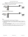
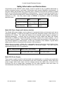
1
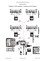
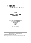
Bell System (Telephones) Ltd Digibell Digital Audio Door Entry System Vandal Resistant Installation & Operation Guide PD-169 Issue 3B Digibell Vandal Resistant System PD-169 Issue 3B Installation Guide Page 2 of 56 Digibell Vandal Resistant System Table of Contents Table of Contents ........................................................................................ 3 Introduction ................................................................................................. 5 Features ...................................................................................................................... 5 System Operation ....................................................................................... 6 Entrance Panel ............................................................................................................ 6 Call sequence.............................................................................................................. 6 Phone Controls............................................................................................................ 7 Design Considerations ............................................................................... 8 Entrance panels .......................................................................................................... 8 Control units ................................................................................................................ 9 Power Supplies ........................................................................................................... 9 Compatible Phones ................................................................................................... 10 Privacy of Speech ..................................................................................................... 10 Extension sounders and flashing strobe.................................................................... 10 Lock Releases ........................................................................................................... 11 Exit button (Egress) ................................................................................................... 11 Fireman’s switch, Break glass or Emergency exit button .......................................... 11 Trades Facility ........................................................................................................... 11 Coded Access Facility ............................................................................................... 11 Multiple Entrances ..................................................................................................... 11 DDA Functionality...................................................................................................... 11 Gate and Block Systems ........................................................................................... 11 Cable requirements................................................................................... 12 Cable Distances ........................................................................................................ 13 Cable overviews ........................................................................................ 14 Diagram 1 – Full Isolation, 1 entrance up to 32 phones ............................................ 15 Diagram 2 - Full isolation, 1 entrance 33 to 64 phones ............................................. 16 Diagram 3 - Zone isolation, 1 entrance up to 32 phones ........................................... 17 Diagram 4 - Zone isolation, 1 entrance 33 to 64 phones ........................................... 18 Diagram 5 - System / Entrance interconnections ...................................................... 19 Installation & Commissioning Guide ...................................................... 20 Installation ................................................................................................................. 20 PD-169 Issue 3B Installation Guide Page 3 of 56 Digibell Vandal Resistant System Commissioning .......................................................................................................... 20 Entrance Panel .......................................................................................................... 20 Electric Door Release................................................................................................ 21 Entry and exit considerations .................................................................................... 21 Exit Button input ........................................................................................................ 21 Door Open Switch ..................................................................................................... 21 Time Clock Sharing ................................................................................................... 21 Entrance Panel Programming ................................................................................... 22 DBA-4I 4 Way Phone Isolator.................................................................................... 27 DBA-8Z 8 Way Zone isolator ..................................................................................... 32 Phone settings........................................................................................................... 38 Troubleshooting ........................................................................................ 40 Common Faults ......................................................................................................... 40 Lock Release Problems ............................................................................................ 40 Entrance Panel Display Problems ............................................................................. 41 Telephone Ring Problems ......................................................................................... 41 Speech Problems ...................................................................................................... 42 Specifications ............................................................................................ 43 Wiring diagrams ........................................................................................ 45 Diagram 6 – Entrance Connections........................................................................... 46 Diagram 7 – Phone Connections (Zone Isolation) ..................................................... 47 Diagram 8 – Phone connections (Full Isolation) ........................................................ 48 Diagram 9 – Isolator Interconnections (single PSU required).................................... 49 Diagram 10 – Isolator interconnections (separate Power supply) ............................. 50 Diagram 11 – Entrance interconnections (BSD-DIG) ................................................ 51 Diagram 12 – Optional Features ............................................................................... 52 Diagram 13 – Combined System Connections .......................................................... 53 Diagram 14 – ACT Proximity Fob system interconnections ...................................... 54 Safety Information and Declarations ...................................................... 55 PD-169 Issue 3B Installation Guide Page 4 of 56 Digibell Vandal Resistant System Introduction The Digibell digital door entry telephone system is designed primarily for large blocks of flats in the private or public housing sector, where reliability and serviceability are of prime importance. The Digibell system offers two levels of cable isolation: ‘Full Isolation’ (between individual dwellings) for buildings where vandalism by residents may be high and ‘Zonal Isolation’ (between floors or zones) for a more cost effective system. The use of a Digital entrance panel (with keypad and display) affords a more compact solution when compared with a standard door entry panel (i.e. one button per flat) which may be impractical due to its size. Features • • • • • • • • • • • • • • • Capacity for over 400 flats and 16 entrances per block Large 4-digit LED display with informative messages, e.g. ‘CALL’, ’TALK’, ‘ OPEN’ Alphanumeric flat numbers, e.g. 20A, B102 High quality full-duplex speech. Ring and lock reassurance tones 4-Digit coded entry facility for resident access Optional Proximity Access Tradesman’s access (time restricted and/or with access code) Dedicated Porter/Reception button. Compliance with Disability Discrimination Act (DDA) (selected panels) Choice of Phone isolation or Zone isolation depending on requirements 12V DC System with optional battery backup Control equipment optionally supplied in lockable Steel cabinets for greater security Uses standard CAT5 cable. Compatible with model 801 & BS-LX telephones PD-169 Issue 3B Installation Guide Page 5 of 56 Digibell Vandal Resistant System System Operation Entrance Panel 0-9, A>, <Z Enter a flat number up to 4 digits. A> & <Z are used to enter the alphabetic characters (A-Z); Press A> to enter A; subsequent presses advance through the alphabet, while <Z can be used to step backwards. For example to enter flat number “C21”, press A> A> A> 2 1 Call Press to call a flat once the correct number is displayed. Cancel Cancels the current entry leaving a blank display. Reception Press to call the Porter / Reception / Concierge Trades Press to gain direct access during restricted hours or using an access code. Call sequence The caller firstly approaches the entrance panel and enters the required flat number followed by the call button. This causes the phone to ring in the selected flat. The phone will continue to ring for typically 30 seconds if not answered or until the resident responds by picking up the handset. The call may be terminated by replacing the handset or more usually by pressing the lock/key button to allow the visitor access through the entrance. PD-169 Issue 3B Installation Guide Page 6 of 56 Digibell Vandal Resistant System Phone Controls All phones have 2-way speech and a lock button to release the door. For security, phones must be called first and taken off the hook before the lock release button will function; a stuck lock button will be ignored. Ringer Mute With some models of telephone (801PS, 801S & BS-LX) the resident can mute the ringing sound of their phone when they do not wish to be disturbed. Model 801PS/801S phones: Sliding the switch on the right hand side to the ON position enables the ringer whilst the OFF position disables (mutes) the ringer. Model BS-LX phone: Ringer mute is activated by pressing the mute button on the phone, which illuminates red as a reminder. Pressing the mute button a second time will disengage the mute function. During installation it is possible to set a time limit for the mute function in various values from 2 minutes up to 10 hours or indefinitely. When this time period has elapsed the mute function will automatically disengage (See ‘Phone settings’ in the reference section). The mute feature stops the audible ring, but the red mute light will still flash to indicate a call and all other functions work normally. Ringer mute will continue for the preset time even if a call is answered. Door Status Indication – BS-LX Only The green lamp on the phone illuminates to warn the resident that a door has been left open following a call. This feature requires a door monitor contact to be fitted. PD-169 Issue 3B Installation Guide Page 7 of 56 Digibell Vandal Resistant System Design Considerations Please read in conjunction with the cable overview drawings starting on page 14 to determine the equipment required for your system. Entrance panels All entrance panels are Stainless Steel Vandal Resistant and have a 4-digit red LED dotmatrix display mounted behind a protective LEXAN window. Both flush and surface types are available. Surface entrance panels can also be supplied fitted to Stainless Steel posts of varying heights for vehicle entrances or where it is impractical to fit directly on a building. The ‘LCP’ version is a flush Stainless Steel panel with welded back-box and laser cut bezel for enhanced vandal resistance. Security screws are supplied with all entrance panel. The entrance panels feature reassurance tones for lock and call operations and a trade’s button/coded access facility (which requires a TS2000-BST time clock). Part No. Description DBAP-VR Flush Stainless Steel digital entrance panel DBAP-VRS Surface/Flush Stainless Steel digital entrance panel DBAP-LCP Flush Stainless Steel digital entrance panel with welded backbox and laser cut front bezel DBAP-DDA Flush Stainless Steel digital DDA* entrance panel DBAP-DDA-S Surface Stainless Steel digital DDA* entrance panel Stainless Steel Posts for surface panels DBAP-VRS & DBAP-DDA-S (not included): CHP1 Car height post, 1200mm PHP1 Pedestrian height post, 1600mm DHP1 Dual height post, pedestrian and car, 1200mm & 1600mm DHP2 Dual height post, HGV and car, 1200mm & 2000mm *DDA entrance panels include yellow halo buttons and have a raised pip on the 5 button. Various other DDA options are available on request. Proximity Fob readers can be integrated into the entrance panels. A standard 40mm square cut-out is used. To specify our standard Paxton Fob reader add the following to each entrance: 1 x PROX/CO Proximity reader cut-out 1 x PAX1 Proximity reader Bell system can also supply Proximity/Fob access systems with added features such as PC management, audit trails, on or offsite management. PD-169 Issue 3B Installation Guide Page 8 of 56 Digibell Vandal Resistant System Other third party readers can be accommodated depending on the size and fitting required. Control units All control equipment must be placed in a protected indoor environment or enclosure. Part No. Description BSD-DIG Digital door controller (1 required per entrance panel) DBA-4I 4 Way phone isolator (1 required every 4 flats) DBA-8Z 8 Way zone isolator (1 required every 8 flats) TS2000-BST Time clock with BST correction (1 required per system for trades facility) Various options are available when the control equipment is placed in one of our Steel lockable cabinets; please contact your sales representative for advice. Power Supplies Please refer to the safety information at the end of this literature Part No. Description PS4 12V DC 4A Regulated power supply 840 12V DC 3A with battery backup (requires a BAT01 12V 7AH battery) BAT01 12V 7AH Lead acid battery Power Supply Requirements (refer to overview drawings starting page 14) 1 entrance + 32 phones 2 entrances (2 x BSD-DIG) 64 Phones: 1 x PS4 or 840 PD-169 Issue 3B 8 4 16 8 DBA-8Z Isolators DBA-8Z Isolators DBA-4I Isolators DBA-4I Isolators with with with with Installation Guide 1 phone in each flat 2 phones in each flat 1 phone in each flat 2 phones in each flat Page 9 of 56 Digibell Vandal Resistant System Compatible Phones Model Privacy of Speech Buzzer mute Slide switch (on/off) Button with indicator; adjustable mute time Door open indicator 801 x x x x 801S x √ x x 801P √ x x x 801PS √ √ x x BS-LX √ x √ √ Phones connected to a DBA-4I Phone Isolator have privacy of speech inherent in the design therefore models 801P and 801PS should not be used. All phones connected to the same DBA-8Z Isolator must be the same model (a mixture of desk or wall mounting is allowed). As standard a maximum of two phones are allowed in each flat. Contact your distributor if more are required. The phones specified above are wall mounting. For a desk-mount model, add ‘–DESK’ to any of the 801 phone series part numbers. Phones can be supplied with a hearing aid induction loop fitted: add ‘-IDL’ to the part number. Privacy of Speech Once a call has been initiated from an entrance panel only the phones which are ringing may answer the call. The conversation cannot be overheard by another phone except an extension phone in the same flat (i.e. one which had also been ringing). This feature is available on systems with Full Isolation (all phone models) and on Zonal Isolation (801P, 801PS and BS-LX models only). Extension sounders and flashing strobe The RT27 extension sounder can be fitted instead of a 2nd phone and has a similar volume level and sound to the 801 series phones. The SG1 sound generator has an adjustable volume level and 8 different tones. The volume is louder than an RT27, but requires an extra 12V DC power supply such as a model 340C. This power supply should be fitted close to the SG1. There is a maximum of 3 units per flat. A FB31 flashing beacon is also available for the hard of hearing. The device requires an extra power supply such as the 340C which should be a short distance from the FB31. There is a maximum of 3 units per flat. Note it is not possible to have a DBA-4I or DBA-8Z Isolator phone output connected to just extension sounders or a strobe, a phone must be present. PD-169 Issue 3B Installation Guide Page 10 of 56 Digibell Vandal Resistant System Lock Releases The BSD-DIG door controller supports both fail-secure and fail-safe lock releases including magnetic locks of up to 1A rating at 12V DC. Suitable transient voltage protection must be fitted across any Maglock or lock release (Some Maglocks have protection inbuilt). If a voltage free output is required for an automatic gate trigger, or connection to another system, an additional 12V DC relay will be needed, e.g. model 89. Whether the lock is released from the phone, the Trades button or Exit button the door will unlock for a pre-programmed time (adjustable 1-99 seconds, default 3 seconds). Various lock releases can be supplied for standard timber frame doors, please contact your sales representative for advice. Exit button (Egress) An input is provided for an exit button, which can be installed on the inside of the door and allow residents to exit freely. Momentary operation of this button will operate the lock release for the programmed lock time. The button must be of the ‘push to make’ type. Fireman’s switch, Break glass or Emergency exit button These should all be wired directly in series with the Fail safe lock release or Maglock itself, so that they break the connection when operated. Trades Facility The Trades button allows access to the postman or other authorized tradesmen usually during restricted hours and, if so programmed, after entering a four digit access code (requires a TS2000-BST time clock). Coded Access Facility The system can allow access with two 4 digit codes. Normally 1 is allocated for use with the Trades facility and the other is used for general resident or caretaker access. The Trades button is used to initiate entry of either code. Multiple Entrances The Digibell system allows multiple entrances to be catered for (up to a maximum of 16) with the addition of a door controller and entrance panel for each entrance and additional power supplies as necessary. DDA Functionality There are a range of options for entrance panels to help meet the requirements of the Disability Discrimination Act (DDA), including Braille characters and hearing aid induction loop. Contact your sales representative for further details. Gate and Block Systems Sites with 2 or more blocks sharing a vehicle or pedestrian gate are catered for with a BSSW Gate/Block isolator (1 per block). The blocks can then work independently but will receive calls from the shared entrances/gates. Please refer to ‘Digibell Gate and Block Supplement. PD-169 Issue 3B Installation Guide Page 11 of 56 Digibell Vandal Resistant System Cable requirements All system wiring must be carried out using CAT5 data cable except were otherwise specified. CAT5 is necessary as it has a guaranteed noise performance and meets the requirements of the EMC directive. Flex or ‘Twin and Earth’ (1.0mm2 min.) is specified for 12V power connections etc ( see table below). Bell System will be unable to offer any warranty or support for systems installed using incorrect cables. Cat5 Cable Specification Cat5 is our short reference for EIA standard UTP Category 5 Unshielded Twisted Pair data cable. This is a standard 0.5mm diameter 0.2mm² solid core twisted pair cable having 4 pairs (8–cores) and no shield. The cores are in pairs where Blue and ‘Blue with a White stripe’ are twisted together as the first pair. The other three pairs are similar with main colours Orange, Green and Brown. • Also available and acceptable are: UTP Category 5e (Cat5e) UTP Category 6 (CAT6) UTP Category 6e (CAT6e) The exact cable can be chosen from the above on cost and availability grounds. • UTP CAT5 Patch cable is normally more expensive, but is suitable. • STP (Shielded Twisted Pair) cables are not recommended. NOTE: Cat5 cable is easily identifiable as the specification is printed on the sheath. PD-169 Issue 3B Installation Guide Page 12 of 56 Digibell Vandal Resistant System Cable Distances Connection No. of Cable cores length Core Type Phone connections DBA-4I/8Z to 1 x 801, 801S or 801PS phone 5 70m DBA-4I/8Z to 2 x 801, 801S or 801PS phones (in the same dwelling) 5 35m DBA-4I/8Z to 1 x BS-LX phone 7 65m DBA-4I/8Z to 2 x BS-LX phones ( in the same dwelling) 7 30m CAT5 Entrance to Control equipment (BSD-DIG Door controller) Entrance Panel DBAP-VR Also –VR(S), -LCP, -DDA(S) 18 PAX1 Fob reader (extra to any entrance panel) +3 Lock release 0.5A 4 1A 8 1A 2 CAT5 Exit button 2 Door monitor contact / switch 2 50m CAT5 1.0mm2 CAT5 System Interconnections DBA-4I / DBA-8Z to Power Supply/BSD-DIG 8 **2 BSD-DIG to BSD-DIG + Trades facility (optional) 6 +1 **1 Power Supply to BSD-DIG 2 3m 1.0mm2 TS2000-BST Time clock to BSD-DIG Door controller (optional) 4 50m CAT5 CAT5 Misc **1 There is no restriction on this distance, except, the maximum overall cable distance between the furthest 2 points (entrance panel to phone via the control equipment) on the system must not exceed 300m. **2 Refer to the cable overview diagrams 1, 2, 3, 4 or 5 For larger cable distances please contact the manufacturer. PD-169 Issue 3B Installation Guide Page 13 of 56 Digibell Vandal Resistant System Cable overviews PD-169 Issue 3B Installation Guide Page 14 of 56 Digibell Vandal Resistant System Cable Overview Diagram 1 – Full Isolation, 1 entrance up to 32 phones PD-169 Issue 3B Installation Guide Page 15 of 56 Digibell Vandal Resistant System Cable overview Diagram 2 - Full isolation, 1 entrance 33 to 64 phones PD-169 Issue 3B Installation Guide Page 16 of 56 Digibell Vandal Resistant System Cable overview Diagram 3 - Zone isolation, 1 entrance up to 32 phones PD-169 Issue 3B Installation Guide Page 17 of 56 Digibell Vandal Resistant System Cable overview Diagram 4 - Zone isolation, 1 entrance 33 to 64 phones PD-169 Issue 3B Installation Guide Page 18 of 56 Digibell Vandal Resistant System Cable overview Diagram 5 - System / Entrance interconnections PD-169 Issue 3B Installation Guide Page 19 of 56 Digibell Vandal Resistant System Installation & Commissioning Guide Installation 1. Review the section headed ‘Safety information’ on Page 55. 2. Check the equipment supplied is as required; refer to the previous section if necessary. 3. Ensure the correct cable type is used (CAT5 and 1.0mm2). 4. Install the system according to instructions in this section. 5. For optional wiring such as a Trades time clock, Fob reader or gate trigger relay refer to diagrams 12, 13 or 14. 6. Fit each component, checking the maximum cable distances shown on the cable overviews in the previous section. Commissioning Settings 1. Set the flat addresses of each DBA-4I or DBA-8Z Isolator referring to the following sections. 2. Entrance and caller settings (speech time, ring time, unlock time, etc) are adjusted through each entrance panel at the associate entrance. Refer to the ‘Entrance panel programming’ section page 22. 3. Settings specific to each phone, such as ring volume and buzzer mute time, when available, are set inside each phone with a jumper or Dipswitch. Refer to the ‘Phone Settings’ section. 4. Speech levels are adjusted at each entrance panel behind the speech grill, with a separate adjustment for each direction of speech. A howling or whistling sound may indicate the volumes levels are set to high. Testing / Connecting The major components of the Digibell system are fitted with high quality pluggable screw terminal blocks. This enables all the connections to the system to be fully completed, whilst easily isolating individual pieces of equipment during testing and commissioning. Any problems can be resolved by rechecking wiring and connections, assisted by the various suggestions and tests in the section ‘Troubleshooting’. Connect up one entrance first, leaving any connection to Isolators or phones unplugged: 1. When powered up for the first time, it is recommended that only the most basic system is connected, i.e. 4/8 phones, 1 BSD-DIG Door controller and entrance panel, 1 DBAxx Isolator, the remaining equipment can be isolated by removing terminal blocks. 2. Check the display and buttons on the entrance panel work as expected. 3. If there is an exit button check the door will unlock. 4. Proceed to test the system by calling each phone from the entrance panel in the normal way, check any available phone features such as buzzer mute or door status. Once the basic system is fully functioning, continue to connect and test equipment item by item until completed. Entrance Panel The mounting height should be considered carefully and applicable standards checked, such as Building regulations and Disabled access. Entrance panels should have mastic applied to PD-169 Issue 3B Installation Guide Page 20 of 56 Digibell Vandal Resistant System the top and side edges of the front plate on the side touching the wall to prevent water ingress behind the panel, but not the bottom edge. On construction sites the panel must be protected from corrosive substances such as ‘brick acid’. The panel should be cleaned only with a damp cloth containing dilute detergent. Electric Door Release Both fail-secure and fail-safe lock releases (including Maglocks) use the same terminals. To change the lock type, refer to the ‘LOCK’ on page 24. When installing lock releases please allow a little movement on the door, as operation will be impaired if fitted too tight or the tongue of the lock extends too deeply into the lock release. N.B. Magnetic locks (Maglocks) must be fitted with suitable transient voltage suppression device at the Maglock. Some Maglock manufacturers fit an internal suppressor. Entry and exit considerations Most fail-secure exit doors incorporate a mechanical means of egress rather than an exit button. Fire officers usually specify a door handle or push bar to open a door on a fire exit route – not, for example, a thumb-turn. Fail secure lock releases are not generally continuously rated however if the entrance needs to be unlocked all day and the door entry system only used at night, then a continuously rated release must be used. Powered bolt, shoot-bolt, Shear lock or other more secure door locking systems may require the use of a separate power supply and relay or a suppressor to be fitted. A not uncommon problem with Maglocks, which cannot be mechanically overridden, is being locked out of the building due to lost codes, fobs or equipment failure. So consider an alternative building entrance, or an externally accessible secure key-switch, or a reliable method of disabling the system during overnight secure lockup. Exit Button input The exit button input is used to unlock the door for the set time (default 3 seconds). The input is designed for use with normally open push buttons. ‘Exit +’ terminal is the input/trigger and ‘Exit –‘ is internally connected to 0V. The ‘Exit +’ input can also be used for connection to other equipment to open the entrance. It is recommended that a relay is used to isolate/interface this connection when using third party equipment. Door Open Switch The door open switch is used to provide an indication at the phone that the door has been left open. This switch can have closed contacts when the door is closed or open contacts when the door is closed; this selection is described in ‘Panel programming’. The default of ‘contact open when door closed’ must be selected when this feature is not required. Time Clock Sharing In a large system a single time clock can be shared between distributed equipment areas by borrowing one of the ‘commn –‘ wires in the interconnecting CAT5 to use as the shared ‘Time clock common’. See the detailed diagram 12. PD-169 Issue 3B Installation Guide Page 21 of 56 Digibell Vandal Resistant System Entrance Panel Programming Several useful settings can be changed using the Entrance panel. This includes. • • • Lock duration Lock type Tradesman and Coded Access Codes (see Table below for full list) Security It is strongly recommended that the Panel Security Code (PSEC) be changed from its factory setting to prevent unauthorized access. Record the new number carefully as it cannot be easily changed if lost. It is also recommended that the Phone Programming Code (PPRG), Coded Access Code (ACOD) and Trades Access Code (TCOD) are all changed from default even if not used. To access panel programming without the code requires physical access to the controller associated BSD-DIG PCB, borrow a jumper from say video gain and place it on the 5 pin programming header between pins 1 & 2 (pin 1 is marked). Now pressing the test button will enter panel programming for 30S when the panel security code can be read or set. When the programming is finished replace the jumper back to its original location. Using Panel Programming Mode:• First type the Panel Security Code (initially 3434) followed by the call button. • The display will show the first programmable parameter (ACOD), (The display alternates, at 1 sec. Intervals, between the parameter name and its value.) • Press the Trades button to step down through the programmable parameters. • Press the Reception button to step up through the programmable parameters. • The list rolls over bottom to top and vice versa. • To change a numeric parameter simply type a new 1-4-digit value and then press call. • Some parameters have a list of options; simply press call to choose the next value. • To exit Panel Program Mode press cancel. • If no button is pressed for 30S then programming mode will auto-cancel. PD-169 Issue 3B Installation Guide Page 22 of 56 Digibell Vandal Resistant System Settings Code Default Access Description ACOD 1234 Coded access code – must be 4 digits TCOD 6789 Trade access code – must be 4 digits LTIM 0003 LOCK Secr Lock Type: Secr (fail secure), Safe (fail safe) CAM2 No Not used TRAD 0005 Trade Function: 0-9 – see table ⇑ Lock Time: 1-99 seconds DMON Cwo Door Monitor Polarity: Cwo, Owo RECP 9898 Reception / Porter phone number PSEC 3434 Panel security code PPRG 1212 Phone programming security code RING 0015 Ring Time – see table TALK 0015 TONE Both Ring and Lock Buzz-Tone enable, 4 settings CANC Yes Not used BCAL No Not used 12A? No Allows user entry of 12A to call DBA-xx output 13 ⇓ Talk Time – see table ACOD – Primary Access Code This is the main code to open the door. It is required when the display prompts with [CODE] after pressing the Trades button. The parameter ‘TRAD’ must be set to ‘Code’ or ‘Trade’ as per the table below. The code must be 4 digits and no letters, leading 0 is OK (e.g. [0246]). TCOD – Secondary Access Code or Tradesmen’s Code This is the tradesmen’s or secondary code to open the door. It is required when the display prompts with [CODE] after pressing the Trades button. The parameter ‘TRAD’ must be set to ‘Trade’ in the active Time Clock setting, as per the table below. The code must be 4 digits and no letters, leading 0 is OK (e.g. [0137]). LTIM – Lock Release Time Door unlocked duration. Range 1 to 99 seconds. Only the last 2 displayed digits are used. A value of 0 will default to 1 second and a value containing alpha characters will default to 3 seconds. PD-169 Issue 3B Installation Guide Page 23 of 56 Digibell Vandal Resistant System LOCK – Lock Type [Secr] = Fail secure lock: - Requires alternate mechanical means, key or thumb-turn to open on power failure. [Safe] = Fail safe lock: - Lock opens on power failure, this includes Maglocks. - Not used on the Digibell system, leave on the default of [No] CAM2 TRAD – Door Button Trades Mode (0-9, default 5) Setting [0] [1] [2] [3] [4] [5] [6] [7] [8] [9] Time Clock Off None None None None Code Code Code Trade Trade Door Time Clock On None Door Code Trade Trade Door Code Trade Door Door ‘None’ = No function; pressing the Trades button is ignored. ‘Door’ = Pressing the Trades button opens the door. ‘Code’ = Pressing the Trades button prompts for the [ACOD] access code to open the door. ‘Trade’ = Pressing the Trades button prompts for either the [ACOD] or [TCOD] access codes to open the door DMON – Door Monitor Switch/Contact [Owc] = Contacts open when door is closed: - This default allows for no switch fitted. [Cwc] = Contacts closed when door is closed: - Standard normally closed switch. RECP – Reception Phone Address The Reception button is used to call a reception desk or similar. The number is that of the called phone. The default is [9898] which is unlikely to be used by a flat. PSEC – Panel Security Key The security key is required to gain access to panel programming. The code is entered then pressing the call button, the default is [3434] and it is recommended that this be changed for security. This code can contain letters and numbers for added security. PPRG – Phone Programming Security Key The phone programming security key is required to gain access to flat number programming of telephones (not normally required). The default is [1212] and it is recommended that this be changed for security. This code can contain letters and numbers for added security. PD-169 Issue 3B Installation Guide Page 24 of 56 Digibell Vandal Resistant System RING – Ringing Time/Call Time and Ring Effect Enter from 0 to 15 as per the table Setting Ring Time Ring Cadence or Sound Effect 0 5s 1 in 3 – 1 ring every 3 seconds 1 8s 1 in 3 – 1 ring every 3 seconds 2 10s 1 in 3 – 1 ring every 3 seconds 3 15s 1 in 3 – 1 ring every 3 seconds 4 20s 1 in 3 – 1 ring every 3 seconds 5 30s 1 in 3 – 1 ring every 3 seconds 6 40s 1 in 3 – 1 ring every 3 seconds 7 45s 1 in 3 – 1 ring every 3 seconds 8 50s 1 in 3 – 1 ring every 3 seconds 9 60s 1 in 3 – 1 ring every 3 seconds 10 30s 1 in 3 (Reserved For future use) 11 30s 1 in 3 (Reserved For future use) 12 30s 2 in 15 – 2 rings, 15S silence, repeat 13 30s 1 in 15 – 1 ring, 15S silence, repeat 14 30s 1 in 5 – 1 ring every 5 seconds 15 30s* 1 in 3* – 1 ring every 3 seconds * Default setting TALK – Talking Time/Phone Active Enter from 0 to 15 as per the table Setting Talk Time Setting Talk Time Setting Talk Time Setting Talk Time 0 15s 4 60s 8 150s 12 60s 1 20s 5 75s 9 180s 13 60s 2 30s 6 90s 10 60s 14 60s 3 45s 7 120s 11 60s 15 60s* * Default setting PD-169 Issue 3B Installation Guide Page 25 of 56 Digibell Vandal Resistant System TONE – Re-assurance Tone To conform to DDA requirements the controller provides a re-assurance tone when a phone is ringing and also when the door lock has been operated from the door panel or the called phone, but not the exit button. In some situations these tones can be considered a nuisance and therefore can be turned off. Four settings are available: [Both] = Ringing and lock tones. [Call] = Ringing tone only. [Lock] = Lock tone only. [None] = No tones. CANC – Not used, leave on the Default of [Yes] BCAL – Not used, leave on the Default of [No] 12A? – Flat 13 Numbered as 12A For use when flat numbering is … 11, 12, 12A, 14, 15 … When set to [Yes] entering “12A call” will actually send “13” so that the DBA-4I/8Z’s can be set to respond to … 11, 12, 13, 14, 15 … BSD-DIG Door Controller Jumper Settings All the jumpers apply to video systems only, so settings have no effect. PD-169 Issue 3B Installation Guide Page 26 of 56 Digibell Vandal Resistant System DBA-4I 4 Way Phone Isolator The DBA-4I Isolator is used to distribute wiring to up to 4 flats, whilst providing isolation between flats. This isolation ensures that a cable fault within one flat will not stop phones within other flats functioning. There is a maximum of 2 phones in each flat. Adding a 2nd phone / extension phone reduces the maximum number of flats that can be powered from the same Power supply. Isolator PCB’s are normally supplied in an individual ABS plastic enclosure, but can be supplied in multiples in a lockable IP55 Steel cabinet (with or without power supplies). All control equipment must be placed in a protected indoor environment. PD-169 Issue 3B Installation Guide Page 27 of 56 Digibell Vandal Resistant System Programming flat addresses The address is the flat number which is entered at the entrance panel in order to call a resident. These addresses are programmed on each of the Isolator PCB’s by selecting the positions of the rotary switch SW6 and the 8-way dipswitch SW7. In the simplest scenario SW6 selects the address of the first phone on the isolator whilst the addresses of the other three follow in sequence as shown in the table below: SW6 Value 0 Phone address (SW7:1-8 = OFF) Phone 1 Phone 2 Phone 3 Phone 4 <address not set> (factory default) SW6 Value Phone address (SW7:1-8 = OFF) Phone 1 Phone 2 Phone 3 Phone 4 8 29 30 31 32 1 1 2 3 4 9 33 34 35 36 2 5 6 7 8 A 37 38 39 40 3 9 10 11 12 B 41 42 43 44 4 13 14 15 16 C 45 46 47 48 5 17 18 19 20 D 49 50 51 52 6 21 22 23 24 E 53 54 55 56 7 25 26 27 28 F 57 58 59 60 Basic Addressing In the most basic numbering scheme each isolator in the system has SW6 set to a different value to create a continuous range of flat addresses: E.g. 32-way system numbered 1-32 Isolator SW6 position Address range First 1 1-4 Second 2 5-8 Third 3 9 - 12 Fourth 4 13 - 16 Fifth 5 17 - 20 Sixth 6 21 - 24 Seventh 7 25 - 28 Eighth 29 - 32 8 Common Numbering Schemes In many buildings the flat numbering does not follow a single sequence as illustrated above; there are often separate sequences for each floor and each sequence begins with a different number (e.g. 101.. 201.. ). Most requirements can be achieved by adding an offset address PD-169 Issue 3B Installation Guide Page 28 of 56 Digibell Vandal Resistant System to each Isolator. This offset enables any start address (i.e. the address of the first flat) to be set between 1 and 3200. The offset address is set using dipswitch SW7: SW7 switch Offset 1 +1 2 +2 3 +50 4 +100 5 +200 6 +400 7 +800 8 +1600 Example [q2e4t6ui] ^ +2 ^ ^ +100 +400 Total offset = +502 Simply add the Total offset value of SW7 switches to the addresses selected by SW6 (See the table on page 28). Example: First Floor 101-108, Second Floor 202-209: Isolator (DBA-4I) Address Range SW6 Position SW7 setting Comment 1 101-104 1 (1-4) 4 ON (+100) Choose 1-4 then add offset of +100 2 105-108 2 (5-8) 4 ON (+100) Choose 5-8 then add offset of +100 3 202-205 1 (1-4) 1, 5 ON (+201) Choose 1-4 then add offset of +201 4 206-209 2 (5-8) 1, 5 ON (+201) Choose 5-8 then add offset of +201 Unused phone connections - Important It may be desirable to use less than 4 connections on a given isolator for convenience of cable or building layout. E.g. if there are 3 flats on each floor: use one isolator per floor. However it is important that in any numbering scheme there are no duplicate flat addresses or the corresponding phones may not operate correctly. All unused outputs should therefore be disabled. Unused outputs must have a wire link placed between O and T on their terminal block. PD-169 Issue 3B Installation Guide Page 29 of 56 Digibell Vandal Resistant System Example: If the 1st floor has flats 1, 2, 3 and the 2nd floor has flats 4, 5, 6 and one Isolator is used for each floor. The 4th Phone output on the 1st floor Isolator will need disabling; otherwise two outputs will try to ring flat 4. Special addressing On the rare occasion when flat numbers skip every other number, e.g. 1,3,5,7 or 2,4,6,8 etc the jumper on the ‘PROG’ 6 pin header can be moved to pins 3 and 4. If flat numbers are required in the range 3200 to 6400 the jumper on the ‘PROG’ 6 pin header can be moved to pins 5 and 6. This simply adds an offset of +3200 to any address set on SW6 and SW7. Alphanumeric Flat Numbers Flat numbers requiring alphabetic characters (e.g. A1-A8, B101-B108, 101C-108C) cannot be programmed on the Isolators and must be programmed into each individual telephone. Please contact Bell System for instructions in this case. PD-169 Issue 3B Installation Guide Page 30 of 56 Digibell Vandal Resistant System Phone ring test This test can be used to ring a phone on one of the four outputs of the DBA-4I isolator to verify basic operation. It can be used to test the ringer, hook switch and lock button operation but not the two way speech. 1. Press the Test button twice to ensure the system is in idle. 2. Set SW7 to test the appropriate phone (only one phone at a time): 1 ON 1st Phone 2 ON 2nd Phone 3 ON 3rd Phone 4 ON 4th Phone 3. Press Test to ring the phone 4. If the phone is taken off-hook the speech light will come on, and go back off when the phone is replaced. 5. If the lock button is pressed, while the speech light is on, the status LED will come on for 3 seconds, if using the BS-LX phone the green LED on the phone will also come on for 3 seconds. 6. Press the test button at any time to cancel. 7. Restore SW7 to the required address setting Diagnostic LEDs LED State Action on LED Status Power up Flashes 3 times Data is present on Data A/B. Brief flash Phone lock button pressed during a call or test On for 3 seconds Test button pressed and system idle Brief flash Restoring factory defaults On for 2 seconds Speech Speech active (call in progress); Ring Test active (no speech) On LED1 1st Phone active On LED2 2nd Phone active On LED3 3rd Phone active On LED4 4th Phone active On Fuse The 12V connection (V terminal) to each flat/phone is individually fused with a standard 20mm fuse, which will need replacing if it fails. PD-169 Issue 3B Installation Guide Page 31 of 56 Digibell Vandal Resistant System DBA-8Z 8 Way Zone isolator The DBA-8Z Isolator is used to distribute wiring to a ‘zone’ of up to 8 flats whilst providing isolation from other zones. This isolation ensures that a cable fault within one zone will not affect the operation of phones within any other zone. It offers a good compromise between equipment cost and ease of maintenance. If greater isolation is required please refer to the DBA-4I Phone Isolator. There is a maximum of 2 phones in each flat. Adding a 2nd phone / extension phone reduces the maximum number of flats that can be powered from the same Power supply. Isolator PCB’s are normally supplied in an individual ABS plastic enclosure, but can be supplied in multiples in a lockable IP55 Steel cabinet (with or without power supplies). All control equipment must be placed in a protected indoor environment. PD-169 Issue 3B Installation Guide Page 32 of 56 Digibell Vandal Resistant System Programming flat addresses The address is the flat number which is entered at the entrance panel in order to call a resident. These addresses are programmed on each of the Isolator PCB’s by selecting the positions of the rotary switch SW6 and the 8-way dipswitch SW7. In the simplest scenario SW6 selects the address of the first phone on the isolator whilst the addresses of the other seven phones follow in sequence as shown in the table below: SW6 Setting Phone address (SW7:1-8 = OFF) Phone 1 Phone 2 Phone 3 0 Phone 4 Phone 5 Phone 6 Phone 7 Phone 8 <address not set> (factory default) 1 1 2 3 4 5 6 7 8 2 5 6 7 8 9 10 11 12 3 9 10 11 12 13 14 15 16 4 13 14 15 16 17 18 19 20 5 17 18 19 20 21 22 23 24 6 21 22 23 24 25 26 27 28 7 25 26 27 28 29 30 31 32 8 29 30 31 32 33 34 35 36 9 33 34 35 36 37 38 39 40 A 37 38 39 40 41 42 43 44 B 41 42 43 44 45 46 47 48 C 45 46 47 48 49 50 51 52 D 49 50 51 52 53 54 55 56 E 53 54 55 56 57 58 59 60 F 57 58 59 60 61 62 63 64 Basic Addressing In the most basic numbering scheme each isolator in the system has SW6 set to a different value to create a continuous range of flat addresses: E.g. 32-way system numbered 1-32 Isolator SW6 position Address range First 1 1-8 Second 3 9-16 Third 5 17-24 Fourth 7 25- 32 PD-169 Issue 3B Installation Guide Page 33 of 56 Digibell Vandal Resistant System Common Numbering Schemes In many buildings the flat numbering does not follow a single sequence as illustrated above; there are often separate sequences for each floor and each sequence begins with a different number (e.g. 101.. 201.. ). Most requirements can be achieved by adding an offset address to each Isolator. This offset enables any start address (i.e. the address of the first flat) to be set between 1 and 3200. The offset address is set using dipswitch SW7: SW7 switch Offset 1 +1 2 +2 3 +50 4 +100 5 +200 6 +400 7 +800 8 +1600 Example [q2e4t6ui] ^ +2 ^ ^ +100 +400 Total offset = +502 Simply add the Total offset value of SW7 switches to the addresses selected by SW6 (See the table on page 33). Example: First Floor 101-116, Second Floor 202-217: Isolator Address (DBA-8Z) Range SW6 Position SW7 setting Comment 1 101-108 1 (1-8) 4 ON (+100) Choose 1-8 then add offset of +100 2 109-116 3 (9-16) 4 ON (+100) Choose 9-16 then add offset of +100 3 202-209 1 (1-8) 1, 5 ON (+201) Choose 1-8 then add offset of +201 4 210-217 3 (9-16) 1, 5 ON (+201) Choose 9-16 then add offset of +201 Unused phone connections - Important It may be desirable to use less than eight connections on a given isolator for convenience of cable or building layout. E.g. if there are 6 flats on each floor: use one isolator per floor. However it is important that in any numbering scheme there are no duplicate flat addresses or the corresponding phones may not operate correctly. All unused outputs should therefore be disabled. PD-169 Issue 3B Installation Guide Page 34 of 56 Digibell Vandal Resistant System Example: Isolator Address SW6 (DBA-8Z) Range Position SW7 setting Comment 1 103-107 1 (1-8) 2, 4 ON (+102) Choose 1-8 then add offset +102 2 108-112 2 (5-12) 1, 2, 4 ON (+103) Choose 5-12 then add offset +103 3 114-122 4 (13-20) 1, 4 ON (+101) Choose 13-20 then add offset +101 In the example above, Isolators 1 and 2 use only five phone connections each; the last three outputs of Isolator 1 would be 108, 109, 110 which, although unused, conflict with the first 3 addresses of Isolator 2; similarly with Isolators 2 and 3. Solution: disable the last three outputs of each isolator. Disabling phone outputs: (Note 1st and 2nd phones cannot be disabled) SW7 setting [1234567i] [123456ui] [12345yui] [1234tyui] [123rtyui] [12ertyui] 1. 2. 3. 4. 5. Phone 1 Phone 2 Phone 3 Phone 4 Phone 5 Phone 6 Phone 7 Seven Phones Used disabled Six Phones Used disabled disabled disabled disabled disabled disabled disabled disabled disabled disabled disabled disabled disabled disabled disabled disabled disabled disabled disabled Five Phones Used Four Phones Used Three Phones Used Two Phones Used disabled Phone 8 On the DBA-8Z isolator set SW7 from the table above: Set SW6 to 0 Press the Test button briefly and confirm the Status LED flashes (2 sec. duration) If required confirm the output status by following the directions below. Return SW6 & SW7 to the correct address setting for the Isolator Confirming status of Isolator Outputs To confirm which phone outputs have been disabled, set SW6 to 0 and SW7 to ‘All OFF’ and press the Test button; each output will have its status LED flash once in turn except those outputs which have been disabled. Note it may be necessary to press the Test button a second time on a live system to ensure that the PCB has been reset. PD-169 Issue 3B Installation Guide Page 35 of 56 Digibell Vandal Resistant System Special addressing On the rare occasion when flat numbers skip every other number, e.g. 1,3,5,7 etc or 2,4,6,8 etc the jumper on the ‘PROG’ 6 pin header can be moved to pins 3 and 4. If flat numbers are required in the range 3200 to 6400 the jumper on the ‘PROG’ 6 pin header can be moved to pins 5 and 6. This simple adds an offset of +3200 to any address set on SW6 and SW7. Alphanumeric Flat Numbers Flat numbers requiring alphabetic characters ( eg A1-A8, B101-B108, 101C-108C) cannot be programmed on the Isolators and must be programmed into each individual telephone. Please contact Bell System for instructions in this case. Phone ring test This can be used to ring a phone on one of the 8 outputs and see off hook and lock button operation. It does not test the speech. 1. Press the Test button twice to ensure the system is in idle 2. Set SW7 to test the appropriate phone (only one phone at a time): 1 ON 1st Phone 2 ON 2nd Phone 3 ON 3rd Phone 4 ON 4th Phone 5 ON 5th Phone 6 ON 6th Phone 7 ON 7th Phone 8 ON 8th Phone 3. Press Test to ring the phone. 4. If the phone is taken off-hook the speech light will come on and go back off when the phone is replaced. 5. If the lock button is pressed the status LED will come on for 3 seconds, if using the BS-LX phone the green LED on the phone will also come on for 3 seconds. 6. Press the test button at any time to cancel. 7. Restore SW7 to the required address setting PD-169 Issue 3B Installation Guide Page 36 of 56 Digibell Vandal Resistant System Diagnostic LEDs LED State Action on LED Status Power up Flashes 3 times Data is present on Data A/B. Brief flash Phone lock button pressed during a call or test On for 3 secs Test button pressed and system idle Brief flash Restoring factory defaults On for 2 secs Speech Speech active (call in progress); Ring Test active (no speech) On Off-hook 1 or more phones are off hook On LED1 LED2 LED3 LED4 LED5 LED6 LED7 LED8 st 1 Phone active 2 nd On Phone active On rd 3 Phone active On th On th On th On th On th On 4 Phone active 5 Phone active 6 Phone active 7 Phone active 8 Phone active Fuses The 12V connection (V on either terminal block) is fused with a standard 20mm fuse, which will need replacing if it fails. There is also an electronic fuse to protect again shorts on the door monitor / contact terminal L. This will reset once the short is removed. PD-169 Issue 3B Installation Guide Page 37 of 56 Digibell Vandal Resistant System Phone settings 801, 801S, 801PS Phones These models have a ring volume with 2 settings high and low marked HI and LO. The default is HI. If the ring is too loud move the jumper at the top left of the PCB to over the 2 pins marked LO. No other adjustments are required. The 801S and 801PS have a slide switch on the right to enable the user to turn the ringer on or off. BS-LX Phones PD-169 Issue 3B Installation Guide Page 38 of 56 Digibell Vandal Resistant System Ringer volume This model has 2 ring levels ‘Low’, ‘Medium’ and ‘High’, the default is ‘High’. It the ringer is too loud move the jumper marked ‘Ring Volume’ on the PCB to the ‘Medium’ or ‘Low’ position. Ringer mute time The phone can be set so that after pressing the mute button the ringer is disabled for a set time and then automatically re-enables itself. This time is adjustable between 2 minutes and 10 hours. It can typically be used to silence the ringer over night. The default setting disables the ringer until the button is pressed again (not cancelling automatically). Refer to the table above or the label inside the phone. The settings for ‘Ring type’, ‘Door Monitor’ and ‘Unlock time’ should be left on the defaults (DIP switch 1-4 should be all OFF) as they are not used on the Digibell system. Phone connections Terminal Meaning I Call (12V to ring) R Microphone speech O Common for ring, speech and lock button (0V) T Speaker Z Lock button (Z shorts to O when the lock button is pressed) V 12V Phone supply (BS-LX only) L Door Monitor (connecting L to 0V brings green LED on, BS-LX only) PD-169 Issue 3B Installation Guide Page 39 of 56 Digibell Vandal Resistant System Troubleshooting Common Faults A very high percentage of calls to our technical support number, regarding new installations, are resolved to faulty wiring. The reasons for these are various: • • • • • Broken cores, especially short links, sometimes broken inside the insulation. Connectors clamped onto the insulation instead of copper. Wires incorrectly positioned in the rising clamp connection of the terminal blocks; unscrew the terminal fully before inserting the wire to prevent it from going “underneath” the clamp. Short or open circuits due to cables having been stapled or nailed through. A common fault is wiring a connector left to right instead of right to left, or one or more twisted pairs the wrong way round. Tip. The heads of screws on connectors are not a reliable means of making a connection with a meter, try pushing the probe into the wire entry point. The following tables provide a quick indication of the possible fault: Lock Release Problems Lock release does not operate or click. (refer to Lock Test below) Connections to the Lock release are open/short-circuited. Voltage drop; cable diameter is too small. Lock current is too high; (PSU is resetting or overloaded.) Lock release jammed due to over tight fitting; check there is some ‘play’ between the lock and lock release. Version number displayed on Entrance Panel (e.g. ‘V3.0’) when operating the lock release Short circuit on the Lock +/- terminals Lock release taking too much current, voltage dipping. Check PSU, cable diameter and Lock release rating. Maglock does not hold strongly. Voltage drop due to cable diameter too small. Holding plate does fully contact magnet. Lock release operates all the time or in reverse Check that the correct lock type is selected: (See ‘Entrance Panel Programming – LOCK’ on page 24) EXIT +/- input short-circuit Exit button is ‘normally closed’ type (should be ‘normally open’) Lock operates from the exit button but not the test button or phone. Normally closed switch has been used for the exit button. Lock Test: Press ‘Test’ Button on Door Controller BSD-DIG (when system is idle): Confirm: ‘LOCK’ LED illuminates for 3 seconds or goes out for 3 seconds depending on lock type selected; Check Output Voltage at LOCK terminals. PD-169 Issue 3B Installation Guide Page 40 of 56 Digibell Vandal Resistant System Entrance Panel Display Problems No display No power at display module BD10; check for a minimum of 10V between +V and 0V. To test the display, turn the power off and then on and check the software version is displayed for a few seconds: Two version numbers are displayed, e.g. “BDV1” then “V4.0”, the presence of the second number confirms the module is receiving data from the BSD-DIG controller ( connection ‘D’). Display indicates “F 1 – –” “D” connection open circuit: No message (data) received from the BSD-DIG controller. Display indicates “F 2 – –” “D” connection shorted to 0V: No message (data) received from the BSD-DIG controller. Telephone Ring Problems Phone doesn’t ring Address not set on the DBA-4I/8Z Isolator; refer to pg. 27/32. I or O terminal not connected on the phone. DBA-4I only – Phone is off-hook. BS-LX phone: Phone is muted. Check red light is off. V, I or O terminal not connected: Check for 12V between V (+) and O (-). Check for 12V between I (+) and O (-) (when the phone should be ringing). Data A or B cores to DBA-4I/8Z isolator open or short circuit or shorted to 0V or 12V at any point. (This would affect all phones on the isolator). Call button or keypad wiring fault; check the correct flat number is displayed and that pressing the Call button displays the word ‘CALL’. Refer to pages 52 and 46. Phone rings briefly then stops Low voltage to the DBA-4I/8Z Isolator; Check the cable requirements page 13. Check there is at least 10V on the 12V+/- connection when the phone should be ringing. BS-LX only - Low Voltage to phone; Check the cable requirements page 13; Check voltage between ‘V’ and ‘O’ on the phone when ringing. Power supply voltage low, due to current overload. Check the voltage at the power supply is 13-14V. PD-169 Issue 3B Installation Guide Page 41 of 56 Digibell Vandal Resistant System BS-LX phone flashes red and green periodically instead of ringing No 12V to connection ‘V’, check 12V between V and O on the phone. Check the fuse on the DBA-4I/8Z isolator hasn’t blown. Speech Problems Loud tone/howl at the entrance speaker. (Acoustic feedback) Low volume speech in one or both directions • Volume controls set too high at entrance • Broken Audio 1 or 2 wire in the cabling (between control equipment). • Intermittent or broken wire in Data A or B • DBA-4I/8Z Isolator has reset; Low voltage to the DBA4I/8Z Isolator connected to that phone. Check the cable requirements page 13. Check at least 10V on the 12V+/connection when the phone should be ringing. • Check model 61 speech unit is hard against the front plate with no gaps. • Check model 61 speech unit is the right way up and that the microphone hole in the speech unit lines up with the hole in the panel. • Adjust pot on 61 speech unit marked A (with a speaker symbol) for volume at the panel. • Adjust pot on 61 speech unit marked B (with a microphone symbol) for volume at the phone. • If volume cannot be increased in one direction without feedback, the volume in the other direction may have to be reduced as a compromise. • Check model 61 is hard against the panel with no gaps. • Check model 61 speech unit is the right way round and that the microphone hole in the speech unit lines up with the hole in the panel. • Another phone (801 or 801S) connected to the same DBA-8Z is off-hook (does not apply to DBA-4I) No speech from phone to entrance • Missing ‘R’ connection to BSD-DIG door controller • Broken or shorted Audio 1 or 2 connections (no speech either direction). No speech from entrance to phone • Missing ‘T’ connection to BSD-DIG door controller • Broken or shorted Audio 1 or 2 connections (no speech either direction). PD-169 Issue 3B Installation Guide Page 42 of 56 Digibell Vandal Resistant System Specifications Model 801/801S/801P/801PS Phone Size 212mm x 85mm x 55mm Supply Voltage 8V DC minimum, 15V DC maximum Current consumption 0mA idle, 140mA max. @13.8V Model BS-LX Phone Size 235mm x 105mm x 25mm Supply Voltage 8V DC minimum, 15V DC maximum Current consumption 26mA idle, 150mA max. @13.8V Model BSD-DIG Door Controller Size 185mm x 230mm x 42mm Supply Voltage 10.8V min, 13.8V typical, 15V max Current consumption 80mA idle, 500mA max @13.8V Includes display and speech Model DBA-4I 4 Way Phone Isolator Size 185mm x 230mm x 42mm Supply Voltage 10V DC min, 15V DC max Current consumption 29mA idle, 75mA max @13.8V Phone Fuses F315mA, 20mm Glass PD-169 Issue 3B Installation Guide Page 43 of 56 Digibell Vandal Resistant System Model DBA-8Z 8 Way Zone Isolator Size 185mm x 230mm x 42mm Supply Voltage 10V DC min, 15V DC max Current consumption 29mA idle, 75mA max @13.8V Phone Fuse F500mA, 20mm Glass Model 61 Speech Unit Size 98mm x 60mm x 24mm Supply Voltage 10V DC min, 15V DC max Current consumption 100mA DC maximum PS4 Power Supply Size 236mm x 105mm x 81mm Reg. Output Voltage 13.8V Nom Output Current 3A continuous, 4A peak (5 minutes max) Mains Internal Fuse Not user replaceable Supply Voltage 230V 50Hz nominal Temperature Range 0 ºC to 50 ºC 840 Power Supply – Battery Backup (requires battery) Size 350mm x 330mm x 80mm Reg. Output Voltage 13.8V Nom Output Current 3A continuous, 4A peak (5 minutes max) Mains Internal Fuse T2A 20mm HBC (HRC) Ceramic Battery Fuse F4A 20mm Glass Supply Voltage 230V 50Hz nominal Temperature Range 0 ºC to 50 ºC PD-169 Issue 3B Installation Guide Page 44 of 56 Digibell Vandal Resistant System Wiring diagrams Full Isolation Zone Isolation Diagram Nos. Diagram Nos. 1 Entrance, 6, 8, 9 6, 7, 9 Up to 32 ways **Overview 1 **Overview 3 1 Entrance, 6, 8, 10 6, 7, 10 32 – 64 ways **Overview 2 **Overview 4 Multi-entrance 6, 8, 9, 11 6, 7, 9, 11 Up to 32 ways **Overview 1,5 **Overview 3,5 Multi-entrance, 6, 8, 10, 11 6, 7, 10, 11 32 - 64 ways **Overview 2,5 **Overview 4,5 System ** Refer to the cable overviews, pages 14 - 19 PD-169 Issue 3B Installation Guide Page 45 of 56 Digibell Vandal Resistant System Diagram 6 – Entrance Connections PD-169 Issue 3B Installation Guide Page 46 of 56 Digibell Vandal Resistant System Diagram 7 – Phone Connections (Zone Isolation) PD-169 Issue 3B Installation Guide Page 47 of 56 Digibell Vandal Resistant System Diagram 8 – Phone connections (Full Isolation) PD-169 Issue 3B Installation Guide Page 48 of 56 Digibell Vandal Resistant System Diagram 9 – Isolator Interconnections (single PSU required) For example 1 – 32 ways PD-169 Issue 3B Installation Guide Page 49 of 56 Digibell Vandal Resistant System Diagram 10 – Isolator interconnections (separate Power supply) For example 32-64 ways PD-169 Issue 3B Installation Guide Page 50 of 56 Digibell Vandal Resistant System Diagram 11 – Entrance interconnections (BSD-DIG) PD-169 Issue 3B Installation Guide Page 51 of 56 Digibell Vandal Resistant System Diagram 12 – Optional Features Time Clock Sharing A time clock can be shared between distributed equipment areas by borrowing one of the ‘commn -’ wires in the interconnecting Cat5 to use as the shared “Time clock common”. The “Time clock common” signal is sharable across all BSD-DIG controllers. Time Clock Common Time Clock Common Blu W/Blu Cat5 Blu + Time W/Blu - + 2 1 B A - Video Audio Data Commn - + 2 1 B A - Video Audio Data Commn + Time BSD-DIG Controller Controller BSD-DIG NC NO CO + - Control Equipment Area 1 TS2000 Time Clock Control Equipment Area 2 Keypad Matrix 1 2 3 1 2 3 4 5 6 7 8 9 <A 0 >Z PD-169 Issue 3B 4 5 6 7 8 X Installation Guide Page 52 of 56 Digibell Vandal Resistant System Diagram 13 – Combined System Connections Connecting a Bell PAX1 Proximity Reader Connect the lock release as per this manual. Leave the Proximity Reader set to fail secure, the BSD-DIG controller sets the lock type. Note 1. A normally open exit button can still be wired to the BSD-DIG controller in addition to the proximity wiring. Opening/Triggering a Gate or Locks on a Third Party System Leave the BSD-DIG controller set to Fail secure. Generally when connecting to a third party system the lock release should be connected as recommended by the other manufacturer; the NO and COM connections from the 89 relay, as shown above, should be connected to a trigger input on the third party system, often marked RTE (request to exit). For further advice please contact your distributor. PD-169 Issue 3B Installation Guide Page 53 of 56 Digibell Vandal Resistant System Diagram 14 – ACT Proximity Fob system interconnections ACTPro1000/2000/3000 Proximity Access Controller ACTPro100/200 Proximity Door Extender Notes 1. Connect the lock release or Maglock using the ACT Manuals. 2. Leave the BSD-DIG controller set to Fail Secure regardless of the type of release used. 3. A normally open exit button can still be fitted to the ACT controller in addition to the Digibell wiring. 4. If the 2 units are not sharing a power supply, then a connection from BSD-DIG controller 12V - to ACT 0V will be required. 5. Look for the notes on the ACT installation diagram concerning the use of links when the door contact is not used and when a power supply without power fail is not used. PD-169 Issue 3B Installation Guide Page 54 of 56 Digibell Vandal Resistant System Safety Information and Declarations Connections to the 240VAC mains supply must be carried out by a qualified electrician or similar competent person, and made in accordance with current legislative requirements. A two pole switch (as provided by a Consumer Unit or Switch Fuse) must be included to isolate both Live and Neutral during Installation or Maintenance. The circuit must be protected by a fuse or other current limiting device, rated according to the capacity of the cable used, up to a maximum of 10A. Use only mains cable to BS6004 or equivalent, within the following specified limits: Min Max Conductor Diameter 1.0mm (0.8mm2) 2.25mm (4mm2) Cable Diameter 4.0mm 8.0mm Model 840 Power Supply (with battery standby) The Model 840 power supply must be placed in a protected indoor environment such as an electrical cupboard. It must be secured to the wall with adequate fixings so that there is no possibility of it falling. The Lead acid battery for the standby power supply is shipped in separate packaging. It should only be connected once the system has been fully tested. Connection is made by 2 leads with spade terminals; observe the correct polarity - red to positive, black to negative. Care must be taken to ensure that the terminals of the battery are not shorted together by metal objects, as this may constitute a Fire Hazard. A good mains safety earth must be connected to all sections of the enclosure. Where the power supply is fitted with a replaceable internal mains fuse and or battery fuse, always replace with the same type as indicated on the power supply. The fuse must be approved to BS EN 60127 or equivalent. Power Supply Model Mains Fuse (Time Delay) 840 Battery Fuse (Quick Blow) T2A 20mm HBC (HRC) Ceramic F4A 20mm Glass Model PS4 Power Supply These power supplies must be wall-mounted onto plasterboard, or a similar non-conductive material, in a protected indoor environment such as an electrical cupboard. When fitting the power supply cable (both mains and low voltage) ensure the cable entry cut-outs in the enclosure lid are no larger than necessary for the cable diameter used and under no circumstances must they be taken beyond the outer cut-out zones. PD-169 Issue 3B Installation Guide Page 55 of 56 Digibell Vandal Resistant System Bell System (Telephones) Ltd. Presley Way, Crown Hill, Milton Keynes MK8 0ET. Tel: FAX: 01908 261106 (Sales and Technical Support) 01908 261116 OR Local rate numbers Tel: FAX: 0845 121 4008 (Sales and Technical Support) 0845 121 4009 E-mail: [email protected] [email protected] Website: www.bellsystem.co.uk Standards This product complies with Electromagnetic Compatibility directive 2004/108/EC and Low Voltage directive 2006/95/EC. Emissions: Generic BSEN 61000-6-3 Immunity: Generic BSEN 61000-6-1 Low Voltage: Generic BSEN 60950 BS EN ISO 9001:2008 Certificate number GB2000389 PD-169 Issue 3B Installation Guide Page 56 of 56