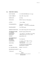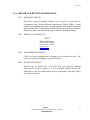
1
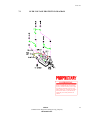
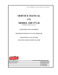
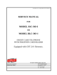
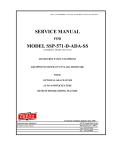
WPP-531-F-AA OR SSP-511-F-AA-SPK1.07UNVLr1-ISSUE4.0
SERVICE MANUAL
FOR
MODEL WPP-531-F-AA
HANDS FREE WEATHERPROOF TELEPHONE
OR
MODEL SSP-511-F-AA
HANDS FREE PANEL TELEPHONE
EQUIPPED WITH SPK1.07 UNVLr1 FIRMWARE
AND
AUTO-ANSWER FEATURE
Serving the Telephone Industry Since 1930
Communication Equipment
& Engineering Company
519 W South Park Street
Okeechobee, FL 34972
Voice: -863-357-0798
Fax: - 863-357-0006
Issue 4.0
IMPORTANT INFORMATION
FOR
CUSTOMER
Please fill in before you continue.
The following information is necessary when calling CEECO for assistance.
MODEL NUMBER
MODEL WPP-531-F-AA OR SSP-511-FAA, EQUIPPED WITH SPK1.07 UNVLr1
FIRMWARE
SERIAL NUMBER
DATE MANUFACTURED
LOCATION INSTALLED
For us to better serve you, please have this information available when calling for technical support.
CEECO
Communication Equipment & Engineering Company
519 W South Park Street
Okeechobee, FL 34972
863-357-0798- telephone
863-357-0006- facsimile
[email protected]
www.ceeco.net
CEECO
Communication Equipment & Engineering Company
PROPRIETARY
2
Issue 4.0
TABLE OF CONTENTS
PAGE
SECTION
1.0
INTRODUCTION............................................................................................................ 4
2.0
GENERAL........................................................................................................................ 4
3.0
PROGRAMMING:.......................................................................................................... 5
PROGRAMMING CONTINUED….............................................................................. 6
PROGRAMMING CONTINUED….............................................................................. 7
PROGRAMMING CONTINUED….............................................................................. 8
4.0
PROGRAMMING TABLES .......................................................................................... 9
PROGRAMMING TABLES CONTINUED… ........................................................... 11
5.0
OPERATION ................................................................................................................. 12
6.0
RECOMMENDED TOOLS AND TEST EQUIPMENT:.......................................... 12
7.0
INSTALLATION NOTES AND ASSEMBLY INSTRUCTIONS: ........................... 13
8.0
TESTING: .................................................................................................................... 144
9.0
SPECIFICATIONS: .................................................................................................... 165
10.0 PARTS LIST: ................................................................................................................. 17
11.0 FCC NOTICE: ............................................................................................................... 18
12.0 REPAIR AND RETURN INFORMATION:............................................................... 19
13.0 WARRANTY POLICY:................................................................................................ 20
AUTO-ANSWER DIAGRAM ...................................................................................... 21
14.0 PROGRAMMING JUMPER DIAGRAM .................................................................. 22
CEECO
Communication Equipment & Engineering Company
PROPRIETARY
3
Issue 4.0
1.0
INTRODUCTION
The practices in this manual provide installation and maintenance information for the
CEECO Model WPP-531-F-AA or SSP-511-F-AA Telephone with SPK1.07 UNVLr1
firmware and Auto-Answer feature.
The information in this manual is subject to change without notification.
For information not included in this manual, please call or write:
CEECO
Customer Service
519 W South Park Street
Okeechobee, FL 34972
863-357-0798- telephone
863-357-0006- facsimile
[email protected]
www.ceeco.net
2.0
GENERAL
2.1
The CEECO hands free telephone is a sturdy, vandal resistant, Stainless Steel
Panel Speakerphone. Instead of a hookswitch and handset, the telephone has a
Press to start/Press to stop button for initiation and termination of phone calls.
2.2
This telephone is equipped with an auto-answer feature, which allows it to be
called from a remote location and answer itself after a selected number of rings.
This allows the phone to be utilized to monitor the area in which it has been
installed, or provide two-way communication. The microphone is muted during
dial tone eliminating the use of hand held dialers.
2.3
Incoming calls may be allowed or blocked depending on the programming.
2.4
Programming is accomplished via the DTMF keypad.
2.5
The WPP-531-F-AA comes with the cast aluminum weatherproof housing,
whereas the SSP-531-F-AA is the panel telephone without the housing.
CEECO
Communication Equipment & Engineering Company
PROPRIETARY
4
Issue 4.0
3.0
PROGRAMMING:
NOTE:
It is recommended that you ground yourself to prevent ESD damage to
the PCB(s).
3.1
Connect the phone to a working telephone line or a DTMF test set before
programming.
3.2
Move the mini-jumpers (located on the Printed Circuit Board) to the
“ON” position, as depicted on the last page of this manual.
3.3
Press the CALL button and wait for dial tone before programming any
digits.
3.4
Each programming memory location is accessed by dialing the "#" sign and a
two digit code. The previous contents of the location are automatically erased
when the location code is accessed.
NOTE: Once the “#" (pound) key has been entered you may get an operator
recording or a fast busy, please disregard and continue programming.
3.5
Enter #97#18# to clear all user programmable memory.
3.6
Enter #00 to access the telephone options location. It is comprised of ten
selected digits, all of which must be filled to render the phone functional. By
entering 0-9 for each of the 10 digits represented on the following page, the
phone is customized to a particular installation. Enter the ten (10) selected
digits now.
CEECO
Communication Equipment & Engineering Company
PROPRIETARY
5
Issue 4.0
PROGRAMMING CONTINUED…
Enter your selections here for future reference:
#00 __
__
0
__
0
0
1 __ 0
5
Digit 1:
0 Call restrictions are in effect. (Default)
1 No call restrictions.
Digit 2:
0 No incoming calls allowed.
1 Incoming calls allowed.
Digit 3:
0 Always 0 for this model
Digit 4:
0 No Conversation Time-Out.
1-9 Minutes Conversation Time-Out (Select a value from 1 to 9 minutes).
Digit 5:
0 Always 0 for this model.
Digit 6:
0
Always 0 for this model.
Digit 7:
1
Always 1 for this model
Digit 8:
0 Do not dial PBX access number #l8
1 Dial PBX access number stored in Location #18
For Call Button
Digit 9:
0 Always 0 for this model.
Digit 10:
0 No Wink Detect
l-9 Length of Wink Detect (l = 50ms incremental to 450ms)
(entering 5 is recommended)
CEECO
Communication Equipment & Engineering Company
PROPRIETARY
6
Issue 4.0
PROGRAMMING CONTINUED…
EXAMPLE:
DIAL #00 0102001005
Phone will be set as follows:
DIGIT 1 .. CALL RESTRICTIONS IN EFFECT
DIGIT 2 .. INCOMING CALLS ALLOWED
DIGIT 3 .. ALWAYS 0
DIGIT 4 .. 2 MINUTE CONVERSATION TIME OUT FOR CALL BUTTON
DIGIT 5 .. ALWAYS 0
DIGIT 6 .. ALWAYS 0
DIGIT 7 .. ALWAYS 1
DIGIT 8 ..DO NOT DIAL PBX NUMBER STORED IN LOCATION #18
DIGIT 9 .. ALWAYS 0
DIGIT 10 . 250ms WINK
3.7
If the telephone must automatically dial (Auto Dial) a number when the
BLACK CALL BUTTON is pressed, enter #18 followed by the desired
number. Otherwise, proceed to the next section.
#18 ___ ___ ___ ___ ___ ___ ___ ___ ___ ___ ___
The number can be from 1 to 11digits. Any number stored in Location #18 will
automatically dial first when the black “Call” button is pressed.
3.8
If Speed Dialing is desired, forty (40) locations are available (#30-#69).
Simply enter each location that will be used followed by the desired number.
Otherwise, proceed to the next section. The numbers can range from 1 to 11
digits. Be sure to record these numbers in section 4.2 for future reference.
EXAMPLE:
Enter #3018005551212 in the programming sequence. When in normal
operating mode, the user dials #30 and the phone will Speed Dial 1-800 5551212.
3.9
If the phone is intended to restrict certain calling patterns, then it must be
programmed to tell it specifically, which calls to allow. If this is not desired,
proceed to the next section. There are twenty (20) locations available (#70#89). Simply enter each location that will be used followed by the
desired/allowed number. The numbers can range from 1 to 11 digits. Be sure
CEECO
Communication Equipment & Engineering Company
PROPRIETARY
7
Issue 4.0
to record these numbers in section 4.3 for future reference.
examples below:
Review the
PROGRAMMING CONTINUED…
NOTE: The * (Asterisk) symbol is defined as a wildcard. A wildcard
allows any digit (0-9) to be emitted from the keypad.
3.10
#70 0-***-***-****
Allows all 0 minus and 0 plus calls.
#71 1-555-1212
Allows 1-555-1212 information calls.
#72 911
Allows 911 emergency calls.
#73 1-800-***-****
Allows 1-800 calls.
AUTO-ANSWER FEATURE
To program the auto-answer feature locate the 660-650 Printed Circuit Board
under the large (660-000) main printed circuit board. Refer to the diagram on
page 20 of this manual. Move the mini-jumper to the desired ring count,
from 1-9.
RING COUNT
0
No auto-answer
1
Answer after 1st ring
2
Answer after 2nd ring
3
Answer after 3rd ring
4
Answer after 4th ring
5
Answer after 5th ring
6
Answer after 6th ring
7
Answer after 7th ring
8
Answer after 8th ring
9
Answer after 9th ring
When in operation, the telephone may be called from a remote location and it
will automatically answer itself after the number of rings, as selected above.
The telephone comes from the factory set to answer after one ring, but this may
be adjusted as stated above.
NOTE: The telephone may be manually answered any time prior to the
activation of the auto-answer feature, at which time conversation may take
place. Example: if the phone is set to auto-answer after nine rings, a person at
the telephone may answer on rings 1-8. At that time, conversation could take
place.
CEECO
Communication Equipment & Engineering Company
PROPRIETARY
8
Issue 4.0
3.11
4.0
When programming is finished, return the mini-jumpers to the
"OFF" position. Then return the phone to an “on hook” state (no dial tone), by
pressing the black "CALL” button.
PROGRAMMING TABLES
4.1
SPEED DIAL TABLE
#30 _ - _ _ _ - _ _ _ - _ _ _ _
#50 _ - _ _ _ - _ _ _ - _ _ _ _
#31 _ - _ _ _ - _ _ _ - _ _ _ _
#51 _ - _ _ _ - _ _ _ - _ _ _ _
#32 _ - _ _ _ - _ _ _ - _ _ _ _
#52 _ - _ _ _ - _ _ _ - _ _ _ _
#33 _ - _ _ _ - _ _ _ - _ _ _ _
#53 _ - _ _ _ - _ _ _ - _ _ _ _
#34 _ - _ _ _ - _ _ _ - _ _ _ _
#54 _ - _ _ _ - _ _ _ - _ _ _ _
#35 _ - _ _ _ - _ _ _ - _ _ _ _
#55 _ - _ _ _ - _ _ _ - _ _ _ _
#36 _ - _ _ _ - _ _ _ - _ _ _ _
#56 _ - _ _ _ - _ _ _ - _ _ _ _
#37 _ - _ _ _ - _ _ _ - _ _ _ _
#57 _ - _ _ _ - _ _ _ - _ _ _ _
#38 _ - _ _ _ - _ _ _ - _ _ _ _
#58 _ - _ _ _ - _ _ _ - _ _ _ _
#39 _ - _ _ _ - _ _ _ - _ _ _ _
#59 _ - _ _ _ - _ _ _ - _ _ _ _
#40 _ - _ _ _ - _ _ _ - _ _ _ _
#60 _ - _ _ _ - _ _ _ - _ _ _ _
#41 _ - _ _ _ - _ _ _ - _ _ _ _
#61 _ - _ _ _ - _ _ _ - _ _ _ _
#42 _ - _ _ _ - _ _ _ - _ _ _ _
#62 _ - _ _ _ - _ _ _ - _ _ _ _
#43 _ - _ _ _ - _ _ _ - _ _ _ _
#63 _ - _ _ _ - _ _ _ - _ _ _ _
#44 _ - _ _ _ - _ _ _ - _ _ _ _
#64 _ - _ _ _ - _ _ _ - _ _ _ _
#45 _ - _ _ _ - _ _ _ - _ _ _ _
#65 _ - _ _ _ - _ _ _ - _ _ _ _
#46 _ - _ _ _ - _ _ _ - _ _ _ _
#66 _ - _ _ _ - _ _ _ - _ _ _ _
#47 _ - _ _ _ - _ _ _ - _ _ _ _
#67 _ - _ _ _ - _ _ _ - _ _ _ _
#48 _ - _ _ _ - _ _ _ - _ _ _ _
#68 _ - _ _ _ - _ _ _ - _ _ _ _
CEECO
Communication Equipment & Engineering Company
PROPRIETARY
9
Issue 4.0
#49 _ - _ _ _ - _ _ _ - _ _ _ _
#69 _ - _ _ _ - _ _ _ - _ _ _ _
CEECO
Communication Equipment & Engineering Company
PROPRIETARY
10
Issue 4.0
PROGRAMMING TABLES CONTINUED…
4.2
ALLOWED CALLS TABLE
#70 _ - _ _ _ - _ _ _ - _ _ _ _
#80 _ - _ _ _ - _ _ _ - _ _ _ _
#71 _ - _ _ _ - _ _ _ - _ _ _ _
#81 _ - _ _ _ - _ _ _ - _ _ _ _
#72 _ - _ _ _ - _ _ _ - _ _ _ _
#82 _ - _ _ _ - _ _ _ - _ _ _ _
#73 _ - _ _ _ - _ _ _ - _ _ _ _
#83 _ - _ _ _ - _ _ _ - _ _ _ _
#74 _ - _ _ _ - _ _ _ - _ _ _ _
#84 _ - _ _ _ - _ _ _ - _ _ _ _
#75 _ - _ _ _ - _ _ _ - _ _ _ _
#85 _ - _ _ _ - _ _ _ - _ _ _ _
#76 _ - _ _ _ - _ _ _ - _ _ _ _
#86 _ - _ _ _ - _ _ _ - _ _ _ _
#77 _ - _ _ _ - _ _ _ - _ _ _ _
#87 _ - _ _ _ - _ _ _ - _ _ _ _
#78 _ - _ _ _ - _ _ _ - _ _ _ _
#88 _ - _ _ _ - _ _ _ - _ _ _ _
#79 _ - _ _ _ - _ _ _ - _ _ _ _
#89 _ - _ _ _ - _ _ _ - _ _ _ _
EXAMPLE:
#70 0 - * * * - * * * - * * * *
Allows all 0 minus and 0 plus
phone calls.
#73 1 - 4 11 - _ _ _ - _ _ _ _
Allows 1411 information calls.
#71 9 - 1 1 _ - _ _ _ - _ _ _ _
Allows 911 emergency calls.
#74 0 - 8 0 0 - * * * - * * * *
Allows 0-800 calls if set in
the option table.
#72 1 - 8 0 0 - * * * - * * * *
Allows 1-800 calls if set in option table.
CEECO
Communication Equipment & Engineering Company
PROPRIETARY
11
Issue 4.0
5.0
OPERATION
5.1
To make a call, press the black "CALL" button located on the front of the
phone. The LED illuminates red at this time. When dial tone is received, the
transmitter is muted and the phone waits for numbers to be dialed.
5.2
After the call is complete, press the "CALL" button again to terminate the call.
If user does not press the "CALL" button when he or she is finished using the
phone, then the phone will hang-up after detecting a WINK (momentary open)
or when the timer times-out, if it was so programmed. The LED will go out at
this time.
5.3
If digit 1 of Location #00 is "0", then call restrictions are in effect. The
numbers that may be dialed are restricted to the numbers entered into Location
#70-#79. If the number dialed is not in the Location #70-#79, then the phone
gives three tones and drops the line.
If digit 1 of Location #00 is "1" then there are no
restrictions and any number may be dialed.
6.0
RECOMMENDED TOOLS AND TEST EQUIPMENT:
DTMF Test Set
Volt/Ohm Meter
3/8" Nut Driver
5/16" Nut Driver
Flat Blade Screw Driver
Security Tool, CEECO Part Number 301-064
CEECO
Communication Equipment & Engineering Company
PROPRIETARY
12
Issue 4.0
7.0
INSTALLATION NOTES AND ASSEMBLY INSTRUCTIONS:
7.1
Using a 301-064 security tool (sold separately), loosen and remove the security
screws.
7.2
The security tool is for a standard 5/32" button head screw generally used on the
framework of the phone booths.
7.3
Separate the faceplate assembly from the weatherproof housing by pulling the
faceplate forward.
7.4
Run the inside station wire into the enclosure and terminate on the RJ11C
terminal block inside, as depicted on the following page. The CEECO provided
terminal block (jack) must be used, as it contains required over-voltage
protection circuitry.
7.5
The use of a gas tube station protector is recommended. The station ground
should not exceed 50 ohms.
7.6
Plug the modular line cord from the faceplate assembly into the RJ11C terminal
block.
7.7
Dress the telephone line cord and AC cable away from the security screws and
seat the faceplate into the weatherproof housing.
7.8
Secure the cover assembly by tightening the security screws.
*****WARNING*****
A.
Never install telephone wiring during a lightning storm.
B.
Never install telephone jacks in wet locations unless the jack is
specifically designed for wet locations.
C.
Never touch non-insulated telephone wires or terminals unless
the telephone line has been disconnected at the network
interface.
D.
Use caution when installing or modifying telephone lines.
CEECO
Communication Equipment & Engineering Company
PROPRIETARY
13
Issue 4.0
7.9
OVER-VOLTAGE PROTECTION DIAGRAM
CONFIDENTIAL
This drawing and all information contained
therein is confidential and is the exclusive
property of CEECO and may not be copied,
reproduced or disclosed to anyone, in any
manner whatsoever, or used for any purpose
other than for which it is provided to you,
without the prior written permission of
CEECO.
CEECO
Communication Equipment & Engineering Company
PROPRIETARY
14
Issue 4.0
8.0
TESTING:
Action:
Connect the phone to a working phone line or DTMF test set.
Press the black "CALL" button.
Reaction:
Red LED and Dial tone.
Action:
Dial a number.
Reaction:
The called party answers.
A normal speakerphone conversation is allowed.
Action:
Finish the conversation.
Press the "CALL" button, or wait until time-out occurs
(if programmed as such).
Reaction:
The call is terminated and LED goes out.
NOTE:
If the telephone was programmed to restrict calls, it should only allow
the numbers to dial as it was programmed. Attempts to dial any other
numbers should result in a three-tone error signal followed by the
telephone dropping the line and resetting itself.
Action:
Call the telephone from a remote/other location.
Reaction:
The telephone should answer itself after the number of rings previously
selected. Upon automatically answering, the telephone provides an open
microphone. This allows the area of the telephone to be monitored for
sound.
Action:
Hang up the calling telephone.
Reaction:
The CEECO telephone will reset, upon receiving the wink back.
CEECO
Communication Equipment & Engineering Company
PROPRIETARY
15
Issue 4.0
9.0
SPECIFICATIONS:
INPUT POWER:
C.O. LINE POWERED (48v-52v Loop)
LOOP CURRENT:
40ma. MIN. 80ma. MAX.
IMPEDANCE:
600 Ohms
SIGNALING:
DTMF, 70ms tone, 50ms spacing
OUTPUT:
-4.0 to -6.0dbm
ENVIRONMENTAL:
Temperature 0°C to 50°C
Humidity
20%-90% non-condensating
PROGRAMMING:
Via DTMF keypad.
MEMORY RETENTION:
Non-volatile storage (does not require power)
TELEPHONE PANEL:
(511 MODEL)
DIMENSIONS:
MOUNTING:
WEIGHT:
Brushed 14 gauge Stainless Steel
WEATHERPROOF
HOUSING:
(531 MODEL)
DIMENSIONS:
7 1/6∀ Wide x 11 1/4∀ High x 4 1/4∀ Deep
4 Holes spaced 10 ¾∀ x 6 ½∀ x 9/32∀
Approximately 4 lb.
Cast Aluminum
WEIGHT:
9 ½” Wide x 12 5/8” High x 8” deep.
(including door).
4 holes spaced 8” x 5 7/8” x 13/32”
(or optional pole mounting bracket)
Approximately 12 pounds.
FCC REGISTRATION:
BW88T7-13716-TE-T
MOUNTING:
RINGER EQUIVALENCY: 0.4A
TYPE JACK:
RJ11C
CEECO
Communication Equipment & Engineering Company
PROPRIETARY
16
Issue 4.0
UL LISTED NO.:
6OF5
10.0 PARTS LIST:
QUANTITY PART NUMBER
DESCRIPTION
4
331-006
Outer Cover Locking- Screw
1
301-018
Modular Line Cord
1
301-054
Modular Connector (RJ11C)
1
N/A
1
700-008
Keypad Cable
1
660-000
CEECO SPK Board
1
705-110
Connectorized Keypad
1
6020
Momentary Panel Switch
1
14123
Speaker
1
12017
Ringer
1
13070
Auto-Answer PCB
Service Manual
ACCESSORIES:
1
301-064
Security Tool
1
331-005
Weatherproof Housing
CEECO
Communication Equipment & Engineering Company
PROPRIETARY
17
Issue 4.0
11.0 FCC NOTICE:
11.1
FCC REGISTRATION AND REPAIR INFORMATION
Your new telephone has been registered with the Federal Communication
Commission (FCC) in accordance with Part 68 of it's rules. The FCC requires
that you be advised of certain requirements involving the use of this telephone.
11.2
CONNECTION WITH THE NATIONWIDE TELEPHONE NETWORK
The FCC requires that you connect this telephone to the Nationwide Telephone
Network through a registered jack provided by the Telephone Company in your
area. This jack is a modular outlet, which you can order from your local
telephone company.
11.3
NOTIFICATION TO THE TELEPHONE COMPANY
Before connecting this telephone, the FCC requires that you notify your local
telephone company business office. The number is in the front of your phone
book.
Tell them:
The "line" to which you will connect the telephone (that is, your phone number)
and the telephone's FCC registration number and ringer equivalence number.
These numbers are listed in Section 11.00.
The FCC further requires that you notify your local telephone company when
permanently disconnecting this telephone
.
CEECO
Communication Equipment & Engineering Company
PROPRIETARY
18
Issue 4.0
12.0 REPAIR AND RETURN INFORMATION:
12.1
WARRANTY REPAIR
Any device returned requiring warranty service; repair or credit must be
accompanied with a "Return Material Authorization" (RMA) FORM. It must
include return shipping instructions, original purchase order number and special
marking instruction. A description of the trouble observed must be attached to
the defective unit. This information must be inside the shipping container.
12.2
DIRECT ALL INQUIRES TO:
CEECO
Repair Department
863-357-0798- telephone
863-357-0006- facsimile
[email protected]
www.ceeco.net
12.3
NON-WARRANTY REPAIR
CEECO will repair equipment out of warranty for a set charge plus parts. The
customer must pay the shipping costs both directions.
12.4
RETURN FOR CREDIT
Material may be returned for credit only with prior approval. Material
authorized for return is subject to a 20% restocking charge based on the
manufacturer’s list price Return RMA must be requested no later than 30 days
after original shipment.
CEECO
Communication Equipment & Engineering Company
PROPRIETARY
19
Issue 4.0
13.0 WARRANTY POLICY:
13.1
GENERAL
CEECO products are guaranteed to be free of defects in material and
workmanship for a period of 365 days from the date of original purchase.
CEECO's obligation under this warranty is limited to repair or replacement of
any part found to be defective by CEECO. Under no circumstances shall
CEECO be liable for loss, damage, cost of repair or consequential damages of
any kind, which have been caused by neglect, abuse, act of God or improper
operation of equipment. This warranty is limited to the value of material only.
13.2
PRINTED CIRCUIT BOARDS
Printed circuit boards should not be repaired in the field. If a unit is found to be
faulty, replace it with another unit and return the faulty unit to CEECO for
repair. Modifications by any one other than CEECO will void the warranty.
CEECO
Communication Equipment & Engineering Company
PROPRIETARY
20
Issue 4.0
AUTO-ANSWER DIAGRAM
Location of ring-select jumpers, on lower auto-answer board:
“ M I N I- J U M P E R ”
CEECO
Communication Equipment & Engineering Company
PROPRIETARY
21
Issue 4.0
14.
PROGRAMMING JUMPER DIAGRAM
Locate the mini jumpers
on the corner of the PCB.
ON
F
OF
Move the mini jumpers
to the ON position
BEFORE going offhook.
ON
F
OF
When programming is
completed, move the
mini jumpers to the OFF
position.
ON
F
OF
NOTE:
Do not leave the mini jumpers in the ON position;
this will decrease battery life.
CEECO
Communication Equipment & Engineering Company
PROPRIETARY
22