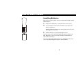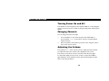
1
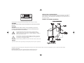
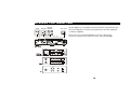
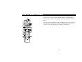
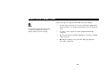
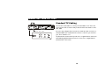
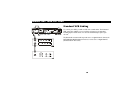
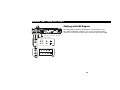
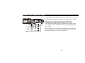
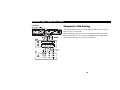
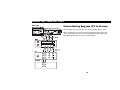
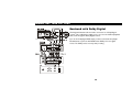
DCT 2000
CURSOR
MESSAGES
REMOTE
A/B
GUIDE
INFO
User Guide
CHANNEL
POWER
MENU
SELECT
A/B
POWER
NOTE TO CATV SYSTEM INSTALLER
CAUTION
RISK OF ELECTRIC SHOCK
DO NOT OPEN
CAUTION: TO REDUCE THE RISK OF ELECTRIC SHOCK,
DO NOT REMOVE COVER (OR BACK).
NO USER-SERVICEABLE PARTS INSIDE.
REFER SERVICING TO QUALIFIED SERVICE PERSONNEL.
This reminder to call the CATV system installer's attention to Article 820-40 of the NEC that
provides guidelines for proper grounding and, in particular, specifies that the cable ground
shall be connected to the grounding system of the building, as close as possible to the point of
cable entry as practical.
EXAMPLE OF ANTENNA GROUNDING
EXAMPLE OF ANTENNAGROUNDING
Graphical symbols and supplemental warning marking locations on bottom of terminal.
WARNING
Electric service
equipment
TO PREVENT FIRE OR SHOCK HAZARD, DO NOT EXPOSE THIS APPLIANCE TO RAIN OR
MOISTURE.
Ground
Antenna lead
clamp
in wire
CAUTION
TO PREVENT ELECTRIC SHOCK, DO NOT USE THIS (POLARIZED) PLUG WITH AN
EXTENSION CORD, RECEPTACLE, OR OTHER OUTLET UNLESS THE BLADES CAN BE
FULLY INSERTED TO PREVENT BLADE EXPOSURE.
The lightning flash with arrowhead symbol, within an equilateral triangle, is
intended to alert the user to the presence of unisulated "dangerous voltage"
within the product's enclosure that may be of sufficient magnitude to constitute a
risk of electric shock to persons.
Antenna
discharge unit
(NEC Section 810-20)
The exclamation point, within an equilateral triangle, is intended to alert the user
to the presence of important operating and maintenance (servicing) instructions
in the literature accompanying the appliance.
This installation should be made by a qualified service person and should conform to all local codes.
REPAIRS
If you find the unit in need of repair, contact your cable system operator for repair or replacement.
Grounding
Grounding conductors
clamps
(NEC Section 810-21)
Power service grounding
electrode system
(NEC Article 250, Part H)
NEC=NATIONAL ELECTRICAL CODE
Copyright © 2000 by Motorola Corporation. All rights reserved. No part of the contents of this book may be reproduced or transmitted in any form or by any means without written
permission of the publisher.
Dolby Digital and Dolby Surround are registered trademarks of Dolby Laboratories, Inc.
Motorola and the Motorola logo are registered trademarks of Motorola Corporation.
IMPORTANT SAFEGUARDS
1
Read instructions
All the safety and operating instructions should
be read before the appliance is operated.
2
Retain instructions
The safety and operating instructions should be
retained for future reference.
3
Heed warnings
All warnings on the appliance and in the
operating instructions should be adhered to.
4
Follow instructions
All operating and use instructions should be
followed.
5
Cleaning
Unplug this product from the wall outlet before
cleaning. Do not use liquid cleaners or aerosol
cleaners. Use a damp cloth for cleaning.
6
7
Attachments
Do not use attachments not recommended
as they may cause hazard.
Water and moisture
Do not use this equipment near water; for
example, near a bathtub, wash bowl, kitchen
sink, or laundry-tub, in a wet basement, or near
a swimming pool, and the like.
8
9
10
Accessories
Do not place this product on an unstable cart,
stand, tripod, bracket, or table. The product may
fall causing serious injury and serious damage to
the appliance. Use only with a cart, stand, tripod,
bracket, or table recommended by the
manufacturer, or sold with the equipment. Any
mounting of the appliance should follow the
manufacturer’s instructions, and should use a
mounting accessory recommended by the
manufacturer.
Ventilation
Slots and openings in the cabinet are provided for
ventilation and to ensure reliable operation of the
equipment and to protect it from overheating. The
openings should never be blocked by placing the
product on a bed, sofa, rug, or similar surface.
Equipment should never be placed near or over a
radiator or heat register, or in a built-in installation
such as a bookcase or rack unless proper
ventilation is provided.
Power sources
This product should be operated only from the
type of power sources indicated on the marking
label. If you are not sure of the type of power
supplied to your home, consult your local power
company. For equipment intended to operate from
battery power, or other sources, refer to the
operating instructions.
11
Ground or polarization
This equipment may be equipped with a polarized
alternating-current line plug (a plug having one
blade wider than the other). This plug will fit into
the power outlet only one way. This is a safety
feature. If you are unable to insert the plug fully
into the outlet, try reversing the plug. If the plug
should still fail to fit, contact your electrician to
replace your obsolete outlet. Do not defeat the
safety purpose of the polarized plug.
12
Alternate warnings
This equipment may be equipped with a 3-wire
grounding-type plug, a plug having a third
(grounding) pin. This pin will only fit into a
grounding-type power outlet. This is a safety
feature. If you are unable to insert the plug into
the outlet, contact your electrician to replace your
obsolete outlet. Do not defeat the safety purpose
of the grounding-type plug.
13
Power cord protection
Power supply cords should be routed so that they
are not likely to be walked on or pinched by items
placed upon or against them, paying particular
attention to cords at plugs, convenience
receptacles, and the point where they exit from
the appliance.
14
Outdoor Antenna Grounding
If an outside antenna or cable system is connected
to the equipment, be sure the antenna or cable
system is grounded as to provide some protection
against voltage surges and built-up static charges.
15
16
17
18
19
Lightning
For added protection for this equipment during
a lightning storm, or when it is left unattended
and unused for long periods of time, unplug it
from the wall outlet and disconnect the antenna
or cable system. This will prevent damage to
the video product due to lightning and power
line surges.
20
Damage requiring service
Unplug this equipment from the wall outlet and
refer servicing to qualified service personnel under
the following conditions:
damaged.
23
Telephone equipment
Observe the following precautions when installing
telephone modem equipment:
b If the equipment has been exposed to rain
or water.
a Never install telephone wiring during a lightning
c If liquid has been spilled, or objects have fallen
storm.
into the equipment.
b Never install telephone jacks in a wet
d If the equipment does not operate normally by
location unless the jack is specifically designed
for wet locations.
following the operating instructions. Adjust
only those controls that are covered by the
operating instructions as an improper
adjustment of other controls may result in
damage and will often require extensive work
by a qualified technician to restore the
equipment to its normal operation.
Overloading
Do not overload wall outlets and extension
cords as this can result in a risk of fire or
electrical shock.
Servicing
Do not attempt to service this equipment
yourself as opening or removing covers may
expose you to dangerous voltage or other
hazards, refer all servicing to qualified
service personnel.
Safety check
Upon completion of any service or repairs to this
video product, ask the service technician to
perform safety checks to determine that the
product is in proper operational condition.
a When the power supply cord or plug is
Power lines
An outside antenna system should not be
located in the vicinity of overhead power lines
or where it can fall into such power lines or
circuits. When installing an outside antenna
system, extreme care should be taken to keep
from touching such power lines or circuits as
contact with them may be fatal.
Object and liquid entry
Never push objects of any kind into this
equipment through openings as they may touch
dangerous voltage points or short-out parts that
could result in a fire or electrical shock. Never
spill liquid of any kind on the product.
22
c Never touch uninsulated telephone wires or
terminals unless the telephone lines have been
disconnected at the network interface.
d Use caution when installing or modifying
telephone lines.
e If the equipment has been dropped or cabinet
has been damaged.
f
21
When the equipment exhibits a distinct change
in performance, indicating a need for service.
Replacement parts
When replacement parts are required, be sure the
service technician has used replacement parts
specified by the manufacturer or have the same
characteristics as the original part. Unauthorized
substitutions may result in fire, electric shock, or
other hazards.
24
Battery usage
Notwithstanding any information provided by GI in
this manual regarding the use of batteries, the end
user assumes all responsibility and liability to use
and dispose of batteries in accordance with all
applicable laws, rules and regulations. GI will not
be liable to anyone for the end user's failure to use
and/or dispose of batteries in the proper manner
and in accordance with such laws, rules and
regulations, or for any defect contained in
batteries which may cause injury damage to
persons or property.
CON TENTS
Introduction..................................................2
Front Panel..........................................................................3
Rear Panel ...........................................................................6
Rear Panel Options...........................................................9
Recording Your Connections..................... 10
Using the Remote Control ......................... 11
Installing Batteries...........................................................15
Basic Operation ...........................................16
Turning Power On and Off ..........................................16
Changing Channels .........................................................16
Adjusting the Volume.....................................................16
Electronic Program Guide ............................................17
Audio/Video Connections...........................18
Connecting your DCT 2000 ........................19
Standard TV Cabling...................................................... 19
Standard VCR Cabling................................................... 20
Cabling with RF Bypass ................................................. 21
Composite Baseband and S-Video ............................. 22
Composite VCR Cabling .............................................. 23
Stereo Cabling Diagram (VCR to Stereo) ............... 24
Stereo Cabling Diagram (TV to Stereo)................... 25
Baseband with Dolby Digital........................................ 26
Troubleshooting......................................... 27
INTRODUCTION
Your DCT 2000 includes one or more of the
following features:
•
Remote control
•
Volume control
•
Parental control
•
Favorite channel recall
•
Sleep and alarm timers
•
Easy Pay-Per-View purchases
•
Electronic program guide (EPG)
•
Video on Demand
•
Digital audio
Congratulations on your purchase of the state-of-the-art DCT 2000 digital
consumer terminal. The DCT 2000 brings unsurpassed digital audio and video
quality to your TV viewing. Electronic program guide menus provide
convenient control of selecting and viewing programs. It’s simple to set up and
easy to operate.
You can purchase Pay-Per-View special events, recent movies or Video on
Demand. Video on Demand is similar to renting a video, including the ability
to pause, rewind, and fast forward.
This guide introduces you to the features and operation of the DCT 2000.
Access to the DCT 2000 features is gained through the electronic
program guide.
Be sure to read your electronic program guide instruction manual to get
the most out of your DCT 2000.
2
INTRODUCTION
Front Panel
The DCT 2000 front panel has 12 keys and an LED display. Use the keys to
perform basic functions such as changing channels and powering on and off.
Display the current channel or time of day on the LED by changing the
default settings in the electronic program guide.
1
CURSOR
GUIDE
2
7
4
5
MESSAGES
REMOTE
A/B
POWER
INFO
6
3
8
MENU
SELECT
9
10
3
CHANNEL
POWER
A/B
11
12
13
INTRODUCTION
Item
Description
1
A/B
Lights if optional switch is activated (see Rear Panel Options)
2
MESSAGES
Lights to indicate that a message is present
Displays current channel number or time of day
3
4
REMO TE
Flashes when an error-free signal is received from the remote control
5
POWER
Lights when the unit is turned on
6
CURSOR
7
8
Displays the electronic program guide
GUIDE
INFO
Moves the cursor in menus and electronic program guide screens
Displays current channel and program information
4
INTRODUCTION
Item
9
10
11
12
13
MENU
Description
Displays the Main menu
SELEC T
Selects menu options, Pay-Per-View (PPV) events, and tunes channels from the electronic program guide
A/B
Manually enables optional modules (a cable-ready TV is required for this function)
CHANNEL
POW ER
Changes the channel up and down
Turns the DCT 2000 on and off
5
INTRODUCTION
Rear Panel
Before you begin installing the DCT 2000 take a moment to become familiar
with the rear panel connections. The rear panel connectors are for system
cabling, and an AC power cord connects the DCT 2000 to an electrical
power outlet. For cabling diagrams, see Connecting Your DCT 2000.
1
TO
TV/VCR
2
3
4
5
6
AUX AUDIO IN
SPDIF
R
L
AUDIO OUT
VIDEO
TO RF IN
S-VIDEO
RF
IN
CABLE IN
8
9
7
HIGH
SPEED
OUT OF
BAND
IR
TV Pass Card
DATA
10 11
6
12
13 14
SWITCHED
105-125V
60Hz
4A MAX
500W MAX
15
INTRODUCTION
Item
Description
1
RF IN
A coaxial input that is connected to the TO RF IN, see Connecting the DCT 2000.
2
TO RF IN
A coaxial input that directs the cable signal to other connections on the DCT 2000.
3
Removable plate
This plate covers the location for an optional telephone module. Available if your service provider offers
telephone communication.
4
AUX AUDIO IN
RCA audio inputs providing loop-through audio from auxiliary audio equipment.
5
SPDIF
A SPDIF RCA connector that provides Dolby Digital audio or PCM audio (digital audio recording). The audio
settings are defined in the electronic program guide.
6
S-VIDEO
An S-Video connector sending high quality video to external devices (high-end VCR or TV) that accept S-Video.
7
Parallel port
A serial data connector to interface external data devices such as a printer.
8
TO TV/VCR
A coaxial output to connect the DCT 2000 to the TV or VCR.
9
CABLE IN
A coaxial input for the incoming signal from the wall outlet.
10
AUDIO OUT
Left/right RCA stereo outputs connect the DCT 2000 to your stereo.
®
7
INTRODUCTION
Item
Description
11
VIDEO
This RCA video output connects the DCT 2000 to a composite (baseband) TV.
12
TV Pass card slot
This space is reserved for future use.
13
Data outputs
For future use with high-speed, high-definition components.
14
IR Output
An RCA output connecting the optional Infrared (IR) Blaster attachment for your DCT 2000.
15
AC power
This is a two-plug AC power outlet. The bottom plug is for attaching a power cord. The top plug can be
configured for plugging in another device such as a TV or VCR.
8
INTRODUCTION
Rear Panel Options
A
CABLE IN
There are four rear panel options that can be included on your DCT 2000.
B
1
RF
OUT
RF
IN
CONV
IN
Sw itch
o ptio n s
Item
Description
1
A/B Switch
This contains coaxial input connectors used
in a dual cable system and with an A/B box.
2
RF Bypass
These coaxial connectors enable the cable
signal to bypass the DCT 2000 and go
directly to a cable-ready TV or VCR.
3
DUAL A/B-RF BYPASS
These coaxial connectors are used in a dual
cable system. The cable signal from A or B
goes directly to a cable-ready TV or VCR.
4
Telco Return
The Telco Return Impulse Pay-Per-View
option is a telephone connection module
that enables you to purchase special
programming on one-way cable systems.
2
A
RF OUT
B
3
PHONE
IP PV
o ptio n
4
9
RECORDING YOUR CONNECTIONS
A/B In
Du al A/B
R F Bypass
R F Bypass
A
RF
OUT
Telco re tu rn
A
RF
IN
RF OUT
CONV
IN
CABLE IN
Use this diagram to record cable connections from the rear panel. Later you
can use this diagram to reconnect your system if you move the equipment,
or add new equipment.
B
B
TO
T V/VCR
Disconnect the power from the DCT 2000 before connecting or changing cable
connections. Do not place another component or object on top of the DCT 2000.
IPPV option
Sw itch
options
AUX AUDIO IN
SPDIF
R
L
AUDIO O UT
VIDEO
TO RF IN
S-VID EO
RF
IN
CAB LE IN
MONITOR
OUT
HIGH
SPEED
OUT OF
BAND
IR
SW IT CHED
105-125V
60Hz
4A MA X
500 W MAX
T V Pass Card
DATA
VIDEO 2
IN
R
L
V
S
R
VIDEO 1
L
V
S
COAXIAL
S-VIDEO VIDEO
IN
OUT R
V
L
S
OPTICAL
AUDIO
IN
R
L
VIDEO
IN
CABLE IN
CABLE OUT
AUDIO
OUT
R
L
S-VIDEO
IN
VIDEO
OUT
S-VIDEO
OUT
AUDIO
IN
R
CABLE IN
TV
AUDIO
OUT
L
VIDEO IN
S-VIDEO IN
VIDEO OUT
S-VIDEO OUT
10
USING THE REMOTE CON TROL
1
VCR
Use the remote control to operate the DCT 2000, TV, and VCR. Many of
the keys on the remote control share the same function as keys on the front
panel.
CA BLE
AU X
2
3
4
5
6
7
8
TV
HELP
POWER
PAGE
11
12
13
PAGE
EXIT
INF O
15
16
17
Your remote control may be different from the one illustrated here. The remote control must
be programmed for use. If your service provider has not programmed your remote control,
refer to the remote control instruction guide supplied by your service provider.
OK
MEN U
VOLUME
9
10
LOCK
LAST
CH ANNEL
FAVORITE
A
B
C
1
2
3
4
5
6
7
8
TV/VCR
REW
PAUSE
RECORD
21
9
ENTER
0
DAY
STOP
18
19
20
DAY
PLAY
22
F.FWD
14
11
USING THE REMOTE CON TROL
Key
Item
Description
1
AUX, VCR, CABLE, or TV
Selects the desired device to control (the selected mode remains active until you press another key)
2
HELP
Displays the help screen
3
POWER
Turns the selected home entertainment component on or off
4
PAGE ▲ or PAGE▼
Pages through menu screens and electronic program guide
5
EXIT
Exits menus and electronic program guide
Moves cursor around the electronic program guide and menu screens
6
7
OK/SELECT
Selects menu options and Pay-Per-View events, or tunes programs from the electronic program
guide (your remote may only have OK; this key performs the same functions)
8
GUIDE
Displays the electronic program guide
12
USING THE REMOTE CON TROL
Key
Item
Description
9
VOLUME + or
VOLUME -
Increases or decreases volume of the currently selected device
10
A, B , or C
Functionality is determined by your service provider
11
NUMBER KEYS
Directly selects a channel
12
TV/VCR
BYPASS
Enables RF bypass function (a cable-ready TV is required for this function)
13
◄ DAY
DAY ►
Use when operating the electronic program guide (moves electronic program guide ahead or back
24 hours)
14
STOP, PAUSE, PLAY,
REW, RECORD, F.FWD
Controls the VCR
15
MUTE
Toggles the sound on and off
13
USING THE REMOTE CON TROL
Key
Item
Description
16
LOCK/PPV
Limits viewing of selected programs, and accesses Pay-Per-View menu (your remote control may only have LOCK;
this key still performs the same functions)
17
INFO
Displays the current channel and program information (not supported by all applications)
18
MENU
Displays the Main menu
19
LAST
Recalls the last channel or goes back one screen in the menu
20
CHANNEL + or
CHANNEL -
Changes the channels up or down
21
FAVORITE
Displays preset favorite cable channels
22
ENTER/MUSIC
Displays digital music channel menus (on some TV models, press to enter channels)
14
USING THE REMOTE CON TROL
Installing Batteries
Before you can use the remote control, you must install two AA (1.5-volt)
alkaline batteries:
1
Slide open the battery door on the back of the remote control.
2
Insert the batteries in the direction indicated on the inside of the
battery compartment.
+
Batteries installed incorrectly can cause battery leakage and corrosion that
will damage the remote control.
+
3
Slide the battery door closed until it snaps into place.
Point the remote control at the DCT 2000, and then press POWER. If the
DCT 2000 does not turn on, check the orientation of the batteries or
replace with new batteries.
Your remote control may be different from the one illustrated here. Refer to the
remote control instruction guide for details on battery installation.
15
BASIC OPERA TION
Turning Power On and Off
Press POWER on the front panel to turn the DCT 2000 on or off. If using the
remote control, be sure it is in cable mode by pressing CABLE, and then press
POWER.
Changing Channels
You can change channels in two ways:
•
Press CHANNEL ▲ or ▼ on the front panel of the DCT 2000, or
press CHANNEL + or - on the remote control to step through the
channel selection.
•
Enter the number of the channel you want to tune using the numeric
keys on the remote control.
Adjusting the Volume
Press VOLUME + or – on the remote control to adjust the volume. When
you adjust the volume, the volume scale is displayed on the screen.
Press MUTE on the remote control to turn the sound off and on again.
For best audio quality, use the remote control to set the DCT 2000 to
approximately ¾ of the maximum volume level and then adjust the audio
levels on the external devices.
16
BASIC OPERA TION
Electronic Program Guide
The electronic program guide displays information about TV programs and
enables you to access features such as Parental Control or Pay-Per-View.
Electronic program guides can vary in look and feel with each service
provider. Reference the electronic program guide instruction manual for
detailed instructions.
17
AUDIO/VIDEO CONNE CTIONS
Before you begin to hookup your DCT 2000, review the following:
NOTE
It is important to remember not to place anything
on top of the DCT 2000 and to provide for
adequate ventilation to prevent overheating.
•
For basic cable connections, use 75-ohm coaxial cables equipped with
F-type connectors. You can find coaxial cables in your local electronics
store.
•
For audio or video outputs, use cables equipped with RCA-type
connectors.
•
Disconnect power from the DCT 2000 before connecting or changing
cable connections.
•
Do not place anything on top of the DCT 2000, especially other
home video components.
18
CONNECTING YOUR DCT 2000
Standard TV Cabling
TO
T V/VCR
AUX AUDIO IN
SPDIF
R
L
AUDIO O UT
VIDEO
TO RF IN
HIGH
SPEED
S-VID EO
RF
IN
CAB LE IN
OUT OF
BAND
T V Pass Card
DATA
F rom c able ou tlet
IR
SW IT CHED
105-125V
60Hz
4A MA X
500 W M AX
D CT 20 0 0
If you are using a diagram that connects the coaxial TO TV/VCR connector on
the DCT 2000 to the coaxial CABLE IN connector on the TV, you must tune
your TV to channel 3 or 4.
AUDIO
IN
R
CABLE IN
AUDIO
OUT
L
Use 75-ohm coaxial cables to connect your DCT 2000 to a TV. This is the
most common cable connection and provides all of the basic features of the
DCT 2000.
VIDEO IN
S-VIDEO IN
VIDEO OUT
S-VIDEO OUT
TV
The illustrated connections will not provide stereo on digital channels. Connect the
DCT 2000 using RCA baseband connectors to receive stereo on digital channels
(illustrated later in this section).
19
CONNECTING YOUR DCT 2000
Standard VCR Cabling
TO
T V/VCR
AUX AUDIO IN
SPDIF
R
L
AUDIO O UT
VIDEO
TO RF IN
HIGH
SPEED
S-VID EO
RF
IN
CAB LE IN
OUT OF
BAND
IR
T V Pass Card
DATA
From cable outlet
AUDIO
IN
R
L
VIDEO
IN
CABLE IN
CABLE OUT
AUDIO
OUT
R
L
To connect your VCR, you will need 75-ohm coaxial cables. The illustrated
VCR connection enables you to record the program you are watching,
including Pay-Per-View events. You can also view videotapes just as you
do now.
The illustrated connections will not provide stereo on digital channels. Connect the
DCT 2000 using RCA baseband connectors to receive stereo on digital channels
(illustrated later in this section).
S-VIDEO
IN
VIDEO
OUT
SW IT CHED
105-125V
60Hz
4A MA X
500 W M AX
S-VIDEO
OUT
AUDIO
IN
R
CABLE IN
AUDIO
OUT
L
VIDEO IN
S-VIDEO IN
VIDEO OUT
S-VIDEO OUT
TV
20
CONNECTING YOUR DCT 2000
Cabling with RF Bypass
TO
T V/VCR
RF
OUT
RF
IN
RF
IN
CONV
IN
AUX AUDIO IN
SPDIF
R
L
AUDIO O UT
VIDEO
TO RF IN
HIGH
SPEED
S-VID EO
CAB LE IN
OUT OF
BAND
IR
T V Pass Card
DATA
SW IT CHED
105-125V
60Hz
4A MA X
500 W M AX
D CT 20 0 0
Su b sc riber telep ho n e h oo ku p
F rom c able ou tlet
This cabling diagram illustrates the RF Bypass module installed on the
DCT 2000. The RF Bypass enables you to view an unscrambled analog
channel on a TV while recording another channel through the DCT 2000.
AUDIO
IN
R
CABLE IN
AUDIO
OUT
VIDEO IN
S-VIDEO IN
VIDEO OUT
S-VIDEO OUT
L
TV
AUDIO
IN
R
L
VIDEO
IN
CABLE IN
CABLE OUT
AUDIO
OUT
R
L
S-VIDEO
IN
VIDEO
OUT
S-VIDEO
OUT
21
CONNECTING YOUR DCT 2000
TO
T V/ VCR
AUX AUD IO IN
SPDIF
R
L
AUDIO OUT
VIDEO
In these illustrations the baseband connectors on entertainment components
are labeled R for right audio, L for left audio, V or VIDEO, and S or S-VIDEO.
TO RF IN
HIGH
SPEED
S-VIDEO
RF
IN
CAB LE IN
OUT OF
BAND
IR
T V Pa ss Ca rd
DATA
D CT 20 0 0
Composite Baseband and S-Video
Connecting the DCT 2000 using the baseband RCA type outputs enables
®
you to experience stereo and Dolby Surround sound on digital channels
when available.
AUDIO
IN
R
CABLE
IN
SW ITCHED
105-12 5V
60Hz
4A MAX
500W M AX
L
VIDEO IN
S-VIDEO IN
VIDEO OUT
S-VIDEO OUT
AUDIO
OUT
When connecting the video path, never connect baseband composite video and
S-Video together. Because some entertainment equipment will not support both
video inputs simultaneously, use only one connection path.
TV
22
CONNECTING YOUR DCT 2000
D CT 20 0 0
Composite VCR Cabling
AUX AUD IO IN
TO
T V/ VCR
SPDIF
TO RF IN
HIGH
SPEED
S-VIDEO
RF
IN
R
L
AUDIO O UT
CAB LE IN
VIDEO
OUT OF
BAND
IR
T V P ass Ca rd
DATA
SW ITCHED
105-12 5V
60Hz
4A MA X
500W M AX
This diagram illustrates how to connect the DCT 2000 to a VCR using the
audio connectors on the VCR.
When connecting the video path, never connect baseband composite video and
S-Video together. Because some entertainment equipment will not support both
video inputs simultaneously, use only one connection path.
AUDIO
IN
R
L
VIDEO
IN
CABLE IN
CABLE OUT
AUDIO
OUT
R
L
S-VIDEO
IN
VIDEO
OUT
S-VIDEO
OUT
TV
AUDIO
IN
R
CABLE IN
AUDIO
OUT
L
VIDEO IN
S-VIDEO IN
VIDEO OUT
S-VIDEO OUT
23
CONNECTING YOUR DCT 2000
D CT 20 0 0
TO
T V/ VCR
Stereo Cabling Diagram (VCR to Stereo)
AUX AUD IO IN
SPDIF
R
L
AUDIO O UT
VIDEO
TO RF IN
HIGH
SPEED
S-VIDEO
RF
IN
CAB LE IN
AUDIO
IN
R
AUDIO
OUT
L
R
IR
DATA
VIDEO
IN
CABLE IN
CABLE OUT
OUT OF
BAND
T V P ass Ca rd
L
S-VIDEO
IN
VIDEO
OUT
SW ITCHED
105-12 5V
60Hz
4A MA X
500W M AX
This diagram illustrates how to connect the DCT 2000 to a stereo using the
audio connectors on the VCR. The VCR sound is played through the stereo.
This configuration does not provide for TV sound to play through the
stereo.
When connecting the video path, never connect baseband composite video and
S-Video together. Because some entertainment equipment will not support both
video inputs simultaneously, use only one connection path.
S-VIDEO
OUT
TV
AUDIO
IN
R
CABLE IN
AUDIO
OUT
L
VIDEO IN
S-VIDEO IN
VIDEO OUT
S-VIDEO OUT
STER EO
AUDIO
IN
R
AUDIO
OUT
L
24
CONNECTING YOUR DCT 2000
D CT 20 0 0
Stereo Cabling Diagram (TV to Stereo)
AUX AUD IO IN
TO
T V/ VCR
This configuration provides for the TV sound to play through the stereo.
SPDIF
TO RF IN
HIGH
SPEED
S-VIDEO
RF
IN
R
L
AUDIO O UT
CAB LE IN
AUDIO
IN
R
VIDEO
AUDIO
OUT
DATA
L
R
IR
T V P ass Ca rd
VIDEO
IN
CABLE IN
CABLE OUT
OUT OF
BAND
L
SW ITCHED
105-12 5V
60Hz
4A MA X
500W M AX
When connecting the video path, never connect baseband composite video and
S-Video together. Because some entertainment equipment will not support both
video inputs simultaneously use only one connection path.
S-VIDEO
IN
VIDEO
OUT
S-VIDEO
OUT
TV
AUDIO
IN
R
CABLE IN
AUDIO
OUT
L
VIDEO IN
S-VIDEO IN
VIDEO OUT
S-VIDEO OUT
STER EO
AUDIO
IN
R
AUDIO
OUT
L
25
CONNECTING YOUR DCT 2000
Baseband with Dolby Digital
TO
T V/ VCR
AU X AUDIO IN
SPDI F
R
L
AU DI O OU T
VI DE O
TO RF I N
HIGH
SPEED
S-VIDE O
RF
IN
CAB LE IN
OUT OF
BAND
IR
SW I TCHE D
105-125V
60H z
4A MAX
500W MAX
T V Pa ss Ca rd
DATA
F rom
cable o utle t
MONITOR
OUT
If you use the Dolby Digital SPDIF output, you must connect both the left/right
baseband audio out from the DCT 2000 and the SPDIF ports to the digital
receiver. The SPDIF port does not carry audio for analog.
VIDEO 2
IN
This diagram illustrates audio and video connections to a Dolby Digital
receiver. This configuration enables you to record on the VCR and playback
with sound through the Dolby Digital receiver.
R
L
V
S
R
VIDEO 1
L
V
S
COAXIAL
S-VIDEO VIDEO
IN
OUT R
L
V
S
OPTICAL
AUDIO
IN
R
L
V
S
CABLE IN
CABLE OUT
AUDIO
OUT
R
L
V
S
TV
AUDIO
IN
R
CABLE IN
AUDIO
OUT
L
VIDEO IN
S-VIDEO IN
VIDEO OUT
S-VIDEO OUT
26
TROUBLESHOOTING
Before calling your service provider, review the troubleshooting guide. This information is to help you quickly solve a problem. If
your problem still exists, contact your service provider.
Problem
Possible Solution
No sound
Press MUTE on the remote control to restore the volume level.
Check that the stereo is looking at the proper input source.
Turn your VCR on.
No picture
Check to be sure that all cables are connected properly (hand-tighten if necessary).
If connected through the baseband RCA video connection, make sure the cables are
connected properly.
If you are watching TV using your VCR, be sure your VCR is on.
Picture or sound is noisy on one channel
Reconnect the cable and hang-tighten if loose.
Sound from only one stereo speaker
Hand-tighten or reconnect the cables properly. Be sure wires are not frayed and plugs
are not bent or broken.
27
TROUBLESHOOTING
Problem
Possible Solution
No power
Reconnect the power cord. Be sure the DCT 2000 is plugged into an outlet that is
always live.
Remote control does not work
Press CABLE on the remote control to ensure the remote control is in cable mode.
Change the batteries in your remote control according to the instructions in the section,
“Installing Batteries.”
Ensure that nothing is on the DCT 2000 or blocking a clear line of sight between it and
the remote control.
Poor audio quality
For best audio quality, use the remote control to set the DCT 2000 to approximately
75% of maximum volume level and then adjust the audio levels on the external devices.
28
466836-001-99
1/00