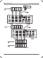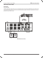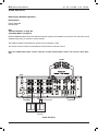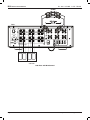
1
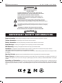
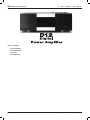
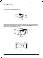
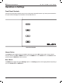
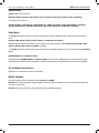
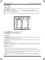
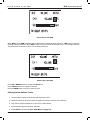
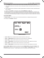
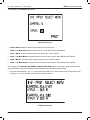
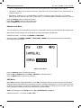
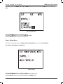
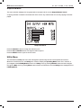
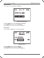
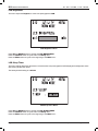
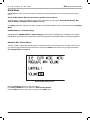
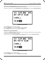
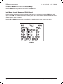
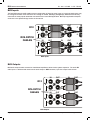
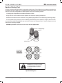
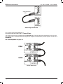
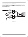
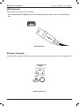
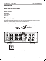
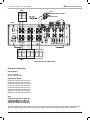
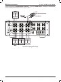
ELAN HOME D12 SYSTEMS INSTALLATION MANUAL Preface Purpose of This Manual This manual provides step-by-step installation instructions and connection examples, along with basic user information for installation and ongoing use of the D12 Digital Power Amplifier. This manual is written for the installer of this equipment. Organization The following information is contained in this manual: Safety Information Provides a comprehensive list of safety practices and procedures allowing for the safe installation and operation of ELAN Home Systems’ D12 Digital Power Amplifier. D12 Introduction Provides an introduction to the D12 Digital Power Amplifier, along with system features to include Front and Rear panel controls, indicators and connections, along with a short description of each. D12 System Design Overview Provides a system design application overview of the D12 Digital Power Amplifier for use in audio applications. D12 Connections Provides a description of D12 Digital Power Amplifier connections including connections made with ELAN Multi-Room Systems and direct connections to the the D12 Digital Power Amplifier from other components. Troubleshooting Provides troubleshooting tables to help fix common discrepancies that may be associated with the D12 Digital Power Amplifier. Specifications Appendix A provides equipment specifications for the D12 Digital Power Amplifier. Rack Mounting Appendix B provides specifications for Rack Mounting of the D12 Digital Power Amplifier using the included Rack Mount Brackets. © ELAN Home Systems 2009 • All rights reserved. Page I D12 ELAN INSTALLATION MANUAL HOME SYSTEMS WARNING RISK OF ELECTRIC SHOCK DO NOT OPEN! CAUTION: TO REDUCE THE RISK OF ELECTRIC SHOCK, DO NOT REMOVE COVER (OR BACK). NO USER SERVICEABLE PARTS INSIDE. REFER SERVICING TO QUALIFIED SERVICE PERSONNEL. CAUTION: RISK OF EXPLOSION IF BATTERY IS REPLACED BY AN INCORRECT TYPE. DISPOSE OF USED BATTERIES ACCORDING TO THE INSTRUCTIONS. The lightning flash with arrowhead symbol within an equilateral triangle is intended to alert the user to the presence of uninsulated "dangerous voltage" within the product's enclosure that may be of sufficient magnitude to constitute a risk of electric shock to persons. The exclamation point within an equilateral triangle is intended to alert the user to the presence of important operating and maintenance (servicing) instruction in the literature accompanying the appliance. WARNING: TO REDUCE THE RISK OF FIRE OR SHOCK, DO NOT EXPOSE THIS APPLIANCE TO RAIN OR MOISTURE. CAUTION IMPORTANT SAFETY INFORMATION Read Information—All the safety and operating information should be read before the appliance is operated. Follow Information—All operating and use information should be followed. Retain Information—The safety and operating information should be retained for future reference. Heed Warnings—All warnings on the appliance and in the operating instructions should be heeded. Wall Mounting—Mounting of this appliance should be done only by an authorized installer. Ventilation—The appliances should be situated so that their location or position does not interfere with their proper ventilation. These appliances should never be placed near or over a radiator or heat register. These appliances should not be placed in a built-in installation such as a bookcase or cabinet that may impede the flow of air through the ventilation openings. Non-Use Periods—Appliances that are left unattended and unused for long periods of time should be de-energized. Power Sources—The appliances should be connected to a power supply only of the type described in the operating instructions or as marked on each appliance. If you are not sure of the type of power supply to your home, consult your authorized ELAN dealer or local power company. Grounding or Polarization—Do not defeat the safety purpose of the polarized or grounding-type plug. A polarized plug has two blades with one blade wider than the other blade. A grounding type plug has two blades and a third grounding prong. The polarized wide blade and the third prong are provided for your safety. If the provided plug does not fit your outlet, consult an electrician for replacement of the obsolete outlet. Page II © ELAN Home Systems 2009 • All rights reserved. ELAN HOME D12 SYSTEMS INSTALLATION MANUAL Water and Moisture—To reduce the risk of electric shock or fire, these appliances should not be used near water––for example, near a bathtub, washbowl, kitchen sink, laundry tub, in a wet basement, or near a swimming pool. Power Cord Protection—Protect the power cord from being walked on or pinched particularly at plugs, convenience receptacles and the point where they exit from the apparatus. Telephones—Avoid using a telephone (other than a cordless type) during an electrical storm. There may be a remote risk of electrical shock from lightning. Do not use a telephone to report a gas leak if the leak is in the vicinity of the ELAN electronic equipment because of risk of fire or explosion. Cleaning—Unplug the apparatus from the power outlet before cleaning. Use only a dry cloth to clean the apparatus. Power Lines—An outdoor antenna should be located away from power lines. When installing an outside antenna system, extreme care should be taken to avoid touching power lines or circuits, as contact with them may be fatal. Outdoor Antenna Grounding—If an outside antenna or cable system is connected to these audio products, be sure the antenna or cable system is grounded so as to provide some protection against voltage surges and built-up static chargesSection 810 of the U.S. National Electrical Code, and Section 54 of the Canadian Electrical Code, provide information with respect to proper grounding of the mast and supporting structure, grounding of the lead-in wire to an antenna discharge unit, size of grounding conductors, location of antenna-discharge unit, connection to grounding electrodes, and requirements for the grounding electrode. See the grounding diagram (right). Grounding Diagram ANTENNA LEAD-IN WIRE GROUND CLAMPS ANTENNA LEAD-IN WIRE (CEC SECTION 54-200) (NEC SECTION 810-20) ELECTRIC SERVICE EQUIPMENT Overloading—Do not overload wall outlets and extension cords, as this could result in fire or electric shock. Object and Liquid Entry—Never insert objects of any kind through the GROUNDING CONDUCTORS (CEC SECTION 54-200) (NEC SECTION 810-21) GROUND CLAMPS NEC - NATIONAL ELECTRICAL CODE CEC - CANADIAN ELECTRICAL CODE POWER SERVICE GROUNDING ELECTRODE SYSTEM (CEC SECTION 10-700) (NEC ARTICLE 250, PART H) openings of these appliances, as they may touch dangerous voltage points or short-out parts that could result in a fire or electric shock. Care should be taken so that objects do not fall and liquids are not spilled into the appliance through openings in the enclosure. Servicing—Do not attempt to service these appliances yourself, as opening or removing covers may expose you to dangerous voltage or other hazards. Refer all servicing to qualified service personnel. Damage Requiring Service—These appliances should be serviced by qualified service personnel when: • • • • • A power supply connection or a plug has been damaged or If liquid has been spilled into the appliance or objects have fallen into the appliance or The appliance has been exposed to water or moisture or The appliance does not appear to operate normally or exhibits a marked change in performance or The appliance has been dropped or the enclosure damaged. Replacement Parts—When replacement parts are required, be sure the service technician has used replacement parts specified by the manufacturer or that have the same characteristics as the original part. Unauthorized substitutions may result in fire, electric shock, or other hazards. The Master Control Unit battery should be replaced only after turning the power off and only by an authorized installer. Safety Check—Upon completion of any service or repairs to this audio product, ask the service technician to perform safety checks to determine that the audio product is in proper operating condition. Lightning Storms—Unplug this apparatus during lightning storms or when unused for long periods of time. Attachments and Accessories—Use only attachments/accessories specified by the manufacturer. Cart, Stand, Tripod, Bracket or Table—Use only with a cart, stand, tripod, bracket or table specified by the manufacturer, or sold with the apparatus. When a cart is used, use caution when moving the cart/apparatus combination to avoid injury from tip over. Disconnect Device—Where the mains plug or an appliance coupler is used as the disconnect device, the disconnect device shall remain operable. © ELAN Home Systems 2009 • All rights reserved. Page III D12 INSTALLATION MANUAL ELAN HOME SYSTEMS Table of Contents Preface�������������������������������������������������������������������������������������������������������������������������������� I Introduction����������������������������������������������������������������������������������������������������������������������� VII D12 Features��������������������������������������������������������������������������������������������������������������������� VII Identification of Controls���������������������������������������������������������������������������������������������������� 1 Rack Mounting ������������������������������������������������������������������������������������������������������������������� 3 Operations & Settings��������������������������������������������������������������������������������������������������������� 4 Front Panel Controls............................................................................................................................................4 Channel Button........................................................................................................................................4 Menu Button.............................................................................................................................................4 UP & DOWN Arrow Buttons.................................................................................................................5 Menu Options........................................................................................................................................................5 Normal Mode.........................................................................................................................................................6 Volume Menu............................................................................................................................................6 Setting System Volume Levels............................................................................................................7 Input Select Menu...................................................................................................................................8 Channel Lock Menu..............................................................................................................................10 ACE Menu................................................................................................................................................10 Power Saving Menu..............................................................................................................................11 Output View Menu. ...............................................................................................................................12 Utility Menu..........................................................................................................................................................12 Operating Mode.....................................................................................................................................13 LCD Contrast..........................................................................................................................................13 LCD Brightness......................................................................................................................................14 LCD Sleep Timer. ..................................................................................................................................14 Power Saving Mode. ............................................................................................................................15 Firmware Version...................................................................................................................................17 Diagnostics Menu..................................................................................................................................17 Ambient Temperature...........................................................................................................................18 Save Dealer Defaults............................................................................................................................18 Restore Defaults....................................................................................................................................20 ELAN Mode..........................................................................................................................................................21 Absolute Max Volume Menu..............................................................................................................21 Minimum Turn-On Volume Menu......................................................................................................22 Page IV © ELAN Home Systems 2009 • All rights reserved. ELAN HOME SYSTEMS D12 INSTALLATION MANUAL Maximum Turn-On Volume Menu.....................................................................................................22 VIA!NET Address...................................................................................................................................23 Channel Range.......................................................................................................................................23 Fault Menu (For both Normal and ELAN Modes).........................................................................24 Connections����������������������������������������������������������������������������������������������������������������������� 25 Line Level Audio Inputs....................................................................................................................................25 BUS Inputs...........................................................................................................................................................26 BUS Outputs........................................................................................................................................................26 Speaker Binding Post. ......................................................................................................................................27 Triggers..................................................................................................................................................................28 IR LOOP INPUT/OUTPUT Connections......................................................................................................30 VIA!NET LOOP INPUT/OUTPUT Connections..........................................................................................31 USB Connector...................................................................................................................................................32 AC Power Connector. .......................................................................................................................................32 Applications����������������������������������������������������������������������������������������������������������������������� 33 Stereo Input with Stereo Output....................................................................................................................33 Multiple Stereo Inputs..........................................................................................................................35 Single Stereo Input with Stereo and Mono Output.....................................................................36 Single Stereo Input with Stereo out on Channels 1 - 8..............................................................38 Stand-Alone Stereo Bussing with Multiple Chassis....................................................................41 Multi-Room Stereo Zones...................................................................................................................43 S128P Sub-Zones.................................................................................................................................44 Troubleshooting����������������������������������������������������������������������������������������������������������������� 47 Specifications�������������������������������������������������������������������������������������������������������������������� 50 © ELAN Home Systems 2009 • All rights reserved. Page V D12 INSTALLATION MANUAL ELAN HOME SYSTEMS Items in package: • D12 Power Amplifier • Rack Mount Brackets • Power Cord • Installation Manual Page VI © ELAN Home Systems 2009 • All rights reserved. ELAN HOME SYSTEMS D12 INSTALLATION MANUAL Introduction Introducing the latest in ELAN digital amplifier design and innovation - the D12 Digital Power Amplifier. Designed specifically for the custom installer, the D12 is the perfect solution for multi-room whole-house applications. Providing cool performance and flexibility, the D12 delivers 12 channels of powerful audio that can be configured into many combinations to suit any situation that may be encountered in a whole-house distributed audio system. The D12 utilizes low heat/high efficiency Class D digital technology which features an 8X over-sampling rate and 48-bit signal processing delivering the cleanest and most efficient audio amplification available. Each channel of the D12 has a true power rating of 75W per channel @ 8 Ohms and 100W per channel @ 4 Ohms - all channels driven. Configuration of the D12 can be done via front panel interface including Advanced setup features such as max volume output, min/max turn on levels. Independent Channel IR commands are available in ELAN's configuration software. D12 Features Class D Digital Technology • Constructed with the highest quality components including Pro-Sound analog to digital (A/D) converters, superior grade capacitors, and high quality 5-way speaker binding terminals, the end result is a sound that is clean, clear and transparent. 75WPC @ 8 Ohms & 100WPC @ 4 Ohms • The D12 combines micro controller technology to maximize efficiency and a muscular Multi-Tap Toroid power transformer to provide all the power necessary to ensure the delivery of deep powerful bass, musical mids and sparkling highs to any whole-house application. Automatic Clipping Eliminator • The D12 Limiter enables the amplified output to be continuously monitored for signal clipping. Intelligent Monitoring • The D12 utilizes advanced micro controller operational circuity that constantly monitors all of the amplifier's operation modes. Channel fault, thermal and impedance load monitoring for each channel provides important diagnostical information. In the event that a problem occurs on a channel during operation, the other channels will continue to provide audio. When the conditions for the troubled channel no longer exist, regular operation will resume after a front panel reset is performed. Multiple Input and Bus Options • The D12 has two stereo Bus inputs that are available to any or all 12 channels. Any stereo pair, including the bus inputs, can be summed internally for a mono channel output. These advanced routing features are programmable setup features through the front panel LCD. The front panel display also provides status monitoring and diagnostics. © ELAN Home Systems 2009 • All rights reserved. Page VII D12 INSTALLATION MANUAL ELAN HOME SYSTEMS Buffered Loop Outputs • Flexible routing of each audio channel without signal loss. IR Control Files • Independent channel Volume Up, Volume Down, Input Selection, Power, Mute, Link/Unlink channel pairs and more. USB Port • For firmware and configuration updates. VIA!Net jack • For control and monitoring. Rack-Mount Brackets Included • Easily mount in a standard equipment rack. Available in 240 Volt Version cTUVus Certified, CE®, and C-tick Page VIII © ELAN Home Systems 2009 • All rights reserved. ELAN HOME D12 SYSTEMS INSTALLATION MANUAL CAUTION This D12 Digital Power Amplifier is capable of delivering in excess of 75 Watts into 8 Ohm loads and in excess of 100 Watts into 4 Ohm loads. All devices connected to the D12, including but not limited to speakers, volume controls, speaker selectors, etc., should have a minimum power handling specification of 75 Watts @ 8 Ohms and 100 Watts @ 4 Ohms. Failure to use properly rated devices can result in damage to the connected device, the amplifier, and may present a fire hazard. © ELAN Home Systems 2009 • All rights reserved. Page IX ELAN HOME D12 SYSTEMS INSTALLATION MANUAL Identification of Controls Front Panel 1 2 3 IR 6 4 5 Front Panel Functions & Indicators Item Description 1 Channel Selector 2 Menu 3 Up Selector 4 Power LED 5 Down Selector 6 IR Icon Display Front Panel Functions & Indicators © ELAN Home Systems 2009 • All rights reserved. Page 1 D12 ELAN INSTALLATION MANUAL HOME SYSTEMS Rear Panel I O 4 3 2 } 1 1 POWER 3 2 5 4 6 IN + + + + + + _ _ _ _ _ _ BUS A SPREAKER OUTPUTS (CLASS 2 WIRING) 75 W/CH @ 8 ohms + + _ T12.5 AL REPLACE WITH SAME TYPE AND RATING ONLY. 7 + + _ _ 8 + 9 + + _ _ 10 + + _ 11 12 5 2 4 6 OUT IN 12 11 OUT 7 9 11 8 10 12 ALL ON INPUT IR IN OUT USB Digital Power Amplifier OUT 3 IR Model D12 13 BUS B IN 1 IN 120V 60 Hz 1440W OUT 5 OUTPUT VIA!NET 10 9 +12VDC TRIGGER OUT 8 IN OUT IN OUT 1/2 3/4 5/6 7/8 9/10 11/12 +12V TRIGGER INPUTS 7 6 Rear Items & Connectors Item Description 1 Power Switch 2 Channels 1-12 Speaker Outputs, 5 Way Binding Post 3 BUS A RCA Stereo Inputs/Outputs, Channels 1 and 2 BUS B RCA Stereo Inputs/Outputs, Channels 7 and 8 4 RCA Stereo Inputs Channels 1-12 5 RCA Stereo Outputs Channels 1-12 6 +12V Channel Pair Trigger Inputs, Triggers 1-2, 3-4, 5-6, 7-8, 9-10, 11-12 7 +12V All On Trigger Input 8 +12V Trigger Output 9 IR Output 10 IR Input 11 VIA!NET Input/Output 12 USB Mini B Port 13 Power Cable Connector Rear Items & Connectors Page 2 © ELAN Home Systems 2009 • All rights reserved. ELAN HOME D12 SYSTEMS INSTALLATION MANUAL Rack Mounting When mounting the D12 in an equipment rack, use the included Rack Mount Brackets for secure mounting and proper ventilation. The D12 requires three rack spaces. To install the D12 into a standard 19” equipment rack: 1. Attach the rack mount bracket onto the D12 chassis from the front as shown in Figure C-1. Figure C-1 2. Ensure that the brackets are flush with the front of the unit. Install each of the eight screws (included) through the side mounting flanges into the holes in the sides of the unit as shown in Figure C-2. Hand tighten screws! Over-tightening could cause damage to the D12 Tuner. Figure C-2 3. Once the brackets are securely mounted, install the entire assembly into a standard 19” equipment rack from the front using four rack screws (not included). Three rack spaces will be used. See Figure C-3. Rack Screws Figure C-3 Rack Screws 19" Equipment Rack © ELAN Home Systems 2009 • All rights reserved. Page 3 D12 ELAN INSTALLATION MANUAL HOME SYSTEMS Operations & Settings Front Panel Controls The D12 front panel buttons provide control for the initial setup and amplifier status. Any button press activates the front panel LCD and displays the information until the LCD times out. Front Panel Controls Channel Button The Channel button toggles through all available channels as well as the ALL channel option. Once a channel has been selected, the UP and DOWN buttons control the MENU item. In the UTILITY menu, the Channel button cycles through the UTILITY sub-menu structure. Menu Button The MENU button toggles through all Settings options. The Settings options will be slightly different depending if you are in Normal Mode or ELAN Mode. Page 4 © ELAN Home Systems 2009 • All rights reserved. ELAN HOME SYSTEMS D12 INSTALLATION MANUAL Normal Mode Normal Mode menu items are: Amplifier Status, Volume, Input Select, Lock, Limiter, Power Saving, Output View, and Utility. The Utility menu items are: Operating Mode, LCD Contrast, LCD Brightness, LCD Sleep Timer, Power Saving Mode, Firmware Version, Diagnostics, Ambient Temperature, Save Dealer Defaults, and Restore Defaults. ELAN Mode The ELAN mode menu items are the same except for the following additional menu items that are after Output View: Absolute Max Volume, Min Turn On Volume, and Max Turn On Volume. Amplifier Status, Volume, Input Select, Lock, Limiter, Power Saving, Output View, Absolute Max Volume, Min Turn On Volume, Max Turn On Volume and Utility The Utility mode menu items are the same except for the following additional menu items that are after Operating Mode: VIA!NET Address and Channel Range. Operating Mode, VIA!NET Address, Channel Range, LCD Contrast, LCD Brightness, LCD Sleep Timer, Power Saving Mode, Firmware Version, Diagnostics, Ambient Temperature, Save Dealer Defaults, and Restore Defaults. UP & DOWN Arrow Buttons Adjusts menu selected item values incrementally. Menu Options The D12 Amplifier has two operating modes, Normal and ELAN. ELAN mode provides feedback through VIA!NET and also allows the amplifier to listen to D12 IR Commands that can effect its channels. Normal mode does not listen to IR Commands or allow VIA!NET feedback. © ELAN Home Systems 2009 • All rights reserved. Page 5 D12 ELAN INSTALLATION MANUAL HOME SYSTEMS Normal Mode Amplifier Status When the MENU button is pressed for the first time, at Power ON, or after 50 seconds of no button activity, the Amplifier Status screen displays. The top of the screen displays what Mode you are in, either ELAN MODE or NORMAL MODE followed by the channels of this chassis I.E. CH1 - CH12. CH1 V50 (CH1). IN1 means that audio input 1 (IN1) is being amplified at 50% (V50) and being routed to channel 1 Amplifier Status Press UP or DOWN buttons to cycle channels four at a time. Press Channel button to cycle one channel at a time. Press the MENU button to move to the next menu. Volume Menu The VOLUME menu will allow any or all channel's volume to be adjusted from 0% (MUTE) to 100% (full gain). The Factory Default setting for each channel is 75. The VU (Volume Unit) bar displays real time (current) volume detected at the selected channel output. The range is from -50 dB to 0 dB. TRIGGER and PS (Power Sense) See "Power Saving Menu" on page 11, "Power Saving Mode" on page 15, and "Triggers" on page 28. Trigger ON is the factory default. The TRIGGER options are: • On: The selected channel is on (consuming energy) and the trigger jack on the rear panel is active. • Off: The selected channel is off (NOT consuming energy) and the trigger jack on the rear panel is not active. • On/PS: The selected channel is off (NOT consuming energy) because the selected channel is in Power Saving Mode even though the trigger jack on the rear panel is active. When ACE is active on the selected channel, ACE will be displayed above Volume %. See "ACE Menu" on page 10. Page 6 © ELAN Home Systems 2009 • All rights reserved. ELAN HOME D12 SYSTEMS INSTALLATION MANUAL Volume Menu with ACE When AVR is active, AVR (Automatic Volume Reduction) is displayed above Volume %. AVR is active whenever the amp is being overdriven. When AVR is active, the D12 turns its volume down until it is not being overdriven. The D12 will turn its volume up when it is not being overdriven. Volume Menu with AVR Press UP or DOWN buttons to change the Volume %. Press Channel button to change the channel. Press the MENU button to move to the next menu. Setting System Volume Levels 1. Set each D12's channel levels by first lowering them to 25%. 2. Raise the volume of all touch panels, touchpads or volume controls to near maximum. 3. Play source program material, such as a CD or a radio station. 4. Have someone step into the room and listen. 5. Enable ACE for all channels. See "ACE Menu" on page 10 © ELAN Home Systems 2009 • All rights reserved. Page 7 D12 ELAN INSTALLATION MANUAL HOME SYSTEMS 6. On the Volume screen, select the channel that is wired to the speaker where the person is listening. 7. Slowly adjust Volume Up for this channel until the audio begins to distort, then drop the level one or two percentages. 8. Follow this procedure for all channels to achieve a good balance of sound from the most used listening position in the zone. 9. Enable or Disable ACE for all applicable channels. See "ACE Menu" on page 10 Note: High volume levels can cause clipping and distortion. This can damage the loudspeaker's components and cause the amplifier to go into protection mode. The protection circuits will reset when the output signal conditions have returned to normal. Overdriving the amplifier can damage the amplifier and void the manufacturer's warranty. Input Select Menu The INPUT SELECT menu will allow any or all of the D12's channels to be configured among six options: This example is with Channel 1 selected. Channel 1 Selected • Input 1 Direct: This is the default, Channel's audio is taken from audio input 1 • Input 1 + 2 Mono Direct: Channel's audio is the sum of audio input 1 and 2 (Mono) • Input 1 Bus A: Channel's audio is taken from audio input 1 which is Bus A • Input 1 + 2 Mono Bus A: Channel's audio is the sum of audio input 1 and 2 (Mono) which is Bus A • Input 7 Bus B: Channel's audio is taken from audio input 7 which is Bus B • Input 7 + 8 Mono Bus B: Channel's audio is the sum of audio input 7 and 8 (Mono) which is Bus B Notice that Input 1 Direct is audio input 1 which is the same as Input 1 Bus A. Also notice that Input 1 + 2 Mono Direct is audio input 1 and 2 summed which is the same as Input 1 + 2 Mono Bus A. This is because the selected channel is channel 1. To help clarify this, see the next example with channel 5 selected. Page 8 © ELAN Home Systems 2009 • All rights reserved. ELAN HOME D12 SYSTEMS INSTALLATION MANUAL This example is with Channel 5 selected. Channel 5 Selected • Input 5 Direct: Default, Channel's audio is taken from audio input 5 • Input 5 + 6 Mono Direct: Channel's audio is the sum of audio input 5 and 6 (Mono) • Input 1 Bus A: Channel's audio is taken from audio input 1 which is Bus A • Input 1 + 2 Mono Bus A: Channel's audio is the sum of audio input 1 and 2 (Mono) which is Bus A • Input 7 Bus B: Channel's audio is taken from audio input 7 which is Bus B • Input 7 + 8 Mono Bus B: Channel's audio is the sum of audio input 7 and 8 (Mono) which is Bus B This example is with Channel ALL EVEN and Channel ALL ODD selected. Instead of a single channel's audio being affected like the previous examples demonstrated, all 12 channels are being affected. • All of the Odd channels (1, 3, 5, 7, 9, 11) are taken from Audio Input 1 which is Bus A and All of the Even channels (2, 4, 6, 8, 10, 12) are taken from audio input 2 which is Bus A All Channel Selected © ELAN Home Systems 2009 • All rights reserved. Page 9 D12 ELAN INSTALLATION MANUAL HOME SYSTEMS • Input 1 + 2 Mono Bus A: All channel's audio is the sum of audio input 1 and 2 (Mono) which is Bus A • Input Direct: Audio Input 1 is routed to channel 1, Audio Input 2 is routed to channel 2, etc...Audio Input 12 is routed to channel 12. • Direct Mono: Audio Input 1 + 2 summed (Mono) is routed to channels 1 and 2, Audio Input 3 + 4 summed (Mono) is routed to channels 3 and 4 etc... Audio Input 11 + 12 summed (Mono) is routed to channels 11 and 12, Press the Channel button to change the channel. Press UP and DOWN buttons to change the option. Press the MENU button to cycle to the next menu. Channel Lock Menu This menu allows any or all channels to be locked or unlocked after initial set-up selections have been determined. When locked, channel settings can not be altered even by IR Commands in ELAN mode. IndIvidual channels 1 - 12 options are LOCKED or UNLOCKED. All channel optons are MIXED, LOCKED, or UNLOCKED. MIXED means that some channels are locked and some channels are not locked. Channel Lock Menu Press the Channel button to change the channel. Press the UP and DOWN buttons to LOCK or UNLOCK the selected channel. Press the MENU button to cycle to the next menu. ACE Menu When ACE (Automatic Clipping Eliminator) is set to ON, the amplified output is continuously monitored for signal clipping. Extremely fast transients are ignored but if it sees a consistent clipping trend, it turns the respective channel down by one increment. This action is repeated until no more clipping is detected for five seconds. After 5 seconds it gradually increases the gain of the channel back to its last setting. ACE will be displayed on the Volume screen. See "Volume Menu" on page 6. IndIvidual channels 1 - 12 options are ON or OFF. Page 10 © ELAN Home Systems 2009 • All rights reserved. ELAN HOME D12 SYSTEMS INSTALLATION MANUAL All channel optons are MIXED, ON or OFF. MIXED means that some channels are ON and some channels are OFF. Channel ACE Menu Press the Channel button to change the channel. Press UP and DOWN buttons to turn the ACE ON or OFF. Press the MENU button to cycle to the next menu. Power Saving Menu This menu is only visible when the Utility's Power Saving Mode menu is set to Per Channel. See "Power Saving Mode" on page 15. Power Saving Press the Channel button to change the channel. Press UP and DOWN buttons to change the Music Sense ON or Off. Press the Menu button to cycle to the beginning of the Main menu. © ELAN Home Systems 2009 • All rights reserved. Page 11 D12 ELAN INSTALLATION MANUAL HOME SYSTEMS Output View Menu This menu selection displays four bar graphs which correspond to the current Output Channel Levels. A clipping indicator is located in the bottom left of the screen. Any channels that are currently clipping will be dispalyed. Output View Menu Press the Channel button to change the channel by one. Press the UP and DOWN buttons to change the channel by four. Press the MENU button to cycle to the next menu. Utility Menu The D12 features a Utility sub-menu that is designed to provide easy access to D12 operational functions. Whenever the LCD times out, the Utility menu resets to display the Operating Mode screen first. However, if you navigate to the LCD Brightness screen in the Utility menu by pressing Channel button and then navigate through the Main menu by pressing Menu button without an LCD timeout, the first Utility screen displayed will be LCD Brightness. Page 12 © ELAN Home Systems 2009 • All rights reserved. ELAN HOME D12 SYSTEMS INSTALLATION MANUAL Operating Mode Places the D12 in either Normal Mode or ELAN Mode. Utility Menu-Operating Mode Press UP and DOWN buttons to select Normal Mode or ELAN Mode. Press the Channel button to cycle to the next Utility menu. Press the Menu button to cycle to the beginning of the Main menu. LCD Contrast This menu adjust the Contast of the front panel graphical LCD. LCD Contrast Menu Press UP and DOWN buttons to change the Contrast. Press the Channel button to cycle to the next Utility menu. Press the Menu button to cycle to the beginning of the Main menu. © ELAN Home Systems 2009 • All rights reserved. Page 13 D12 ELAN INSTALLATION MANUAL HOME SYSTEMS LCD Brightness This menu adjust the Brightness of the front panel graphical LCD. LCD Brightness Menu Press UP and DOWN buttons to change the LCD BRIGHTNESS. Press the Channel button to cycle to the next Utility menu. Press the Menu button to cycle to the beginning of the Main menu. LCD Sleep Timer This menu setting determines the amount of time that the front panel graphical LCD display and backlight are active after a front panel button press. The factory default setting is 1 minute. LCD Sleep Timer Menu Press UP and DOWN buttons to change the LCD SLEEP TIMER. Press the Channel button to cycle to the next Utility menu. Press the Menu button to cycle to the beginning of the Main menu. Page 14 © ELAN Home Systems 2009 • All rights reserved. ELAN HOME SYSTEMS D12 INSTALLATION MANUAL Power Saving Mode The Power Saving mode uses Music Sense detection to determine if audio signals are present. If signals are not present, the enabled amplifier channels power OFF. When a source signal is detected the channels power ON. The factory default is ALL ENABLED. When ALL ENABLED is selected, any channel will shut itself off after 5 minutes when it no longer detects audio. ALL ENABLED examples: • If a zone is turned off on an ELAN's system controller and the system controller's triggers are not connected, the D12's channels will turn off after 5 minutes of not detecting audio. • If a zone is muted on the ELAN's system controller, the D12's channels will turn off after 5 minutes of not detecting audio. When the PER Channel setting is selected, a hidden MAIN menu appears called POWER SAVING MENU. This allows Music Sense to be selected for EACH channel or ALL channels. See "Power Saving Menu" on page 11. PER Channel examples: • The D12 may drop out in ALL ENABLED mode if the audio being sent to it is at a soft level (15%). This level may be audible to the human ear but the D12 thinks it is noise. Since the D12 thinks it is noise, the channel is turned off after 5 minutes. To prevent the channel from dropping out, place the POWER SAVING MODE in PER Channel. Then go to POWER SAVING Menu and set the channel to Music Sense OFF. With Music Sense Off, the D12 will only turn off the channel with Trigger inputs. See "Triggers" on page 28. © ELAN Home Systems 2009 • All rights reserved. Page 15 D12 ELAN INSTALLATION MANUAL HOME SYSTEMS Power Saving Mode Menus Page 16 © ELAN Home Systems 2009 • All rights reserved. ELAN HOME D12 SYSTEMS INSTALLATION MANUAL Firmware Version This menu displays the current Firmware Version presently downloaded to the D12 chassis. Firmware Version Menu Press the Channel button to cycle to the next Utility menu. Press the Menu button to cycle to the beginning of the Main menu. Diagnostics Menu The Diagnostics menu provides easy access to current D12 system status. Diagnostics information displayed on the D12’s front panel include the number of times the unit has suffered fault conditions (F) and high temperatures (T) for each channel. A Fault (F) problem will occur when a channel is shorted or the impedance drops below 4 ohms. A Temperature (T) problem will occur when the temperature rises above 125C. Diagnostics Menu Press UP and DOWN buttons to change to other channels. Press the Channel button to cycle to the next Utility menu. Press the Menu button to cycle to the beginning of the Main menu. © ELAN Home Systems 2009 • All rights reserved. Page 17 D12 ELAN INSTALLATION MANUAL HOME SYSTEMS Ambient Temperature This menu displays the current AMBIENT TEMPERATURE of the D12 chassis as well as minimum and maximum temperatures that are logged in memory. Ambient Temperature Menu Press UP and DOWN buttons to change from Celsius to Fahrenheit. Press the Channel button to cycle to the next Utility menu. Press the Menu button to cycle to the beginning of the Main menu. Save Dealer Defaults A 4 digit PIN code may be used to save all Dealer Default settings. This PIN is set to 3526 and can not be changed. To save the current settings: Press UP and DOWN buttons to change the digits to 3526. Press the Channel button to cycle to the next digit. To advance to the next menu, press the Channel button repeatedly. Save Defaults/PIN Menu Page 18 © ELAN Home Systems 2009 • All rights reserved. ELAN HOME D12 SYSTEMS INSTALLATION MANUAL Pressing the Channel button on the fourth digit when 3526 was added will display: Save Dealer Defaults Save/No Save Press UP and DOWN buttons to select SAVE or NO SAVE. Press the Channel button to commit the selection and cycle to the next Utility menu. Press the Menu button to commit the selection and cycle to the beginning of the Main menu. Pressing the Channel button on the fourth digit when 3526 was NOT entered: Press UP and DOWN buttons to select SAVE or NO SAVE. Press the Channel button when NO SAVE is the selection will cycle to the next Utility menu. Press the Channel button when SAVE is the selection will display the following for two seconds and then hightlight the first digit so the correct pin can be entered: Saving Dealer PIN: Retry Press the Menu button to CANCEL and cycle to the beginning of the Main menu. © ELAN Home Systems 2009 • All rights reserved. Page 19 D12 ELAN INSTALLATION MANUAL HOME SYSTEMS Restore Defaults This menu allows the restoration of amplifier settings. The options are DO NOT RESTORE, FACTORY, and DEALER. Restore Defaults Menu Press UP and DOWN buttons to change Options. Press the Channel button to display Cancel and Save. Restore Defaults Menu Cancel/Restore Press UP and DOWN buttons to select CANCEL or Restore. Press the Channel button to commit the selection. If Restore is selected the D12 will immediately restore the selected defaults. Press the Menu button to cycle to the beginning of the Main menu. Page 20 © ELAN Home Systems 2009 • All rights reserved. ELAN HOME D12 SYSTEMS INSTALLATION MANUAL ELAN Mode The ELAN mode menu items are the same except for the following additional menu items that are after Output View: Absolute Max Volume, Min Turn On Volume, and Max Turn On Volume. Amplifier Status, Volume, Input Select, Lock, Limiter, Power Saving, Output View, Absolute Max Volume, Min Turn On Volume, and Max Turn On Volume and Utility The Utility mode menu items are the same except for the following additional menu items that are after Operating Mode: VIA!NET Address and Channel Range. Operating Mode, VIA!NET Address, Channel Range, LCD Contrast, LCD Brightness, LCD Sleep Timer, Power Saving Mode, Firmware Version, Diagnostics, Ambient Temperature, Save Dealer Defaults, and Restore Defaults. Absolute Max Volume Menu This will not allow channel gain adjustments for individual channels or All channels to be set higher than this setting. Channel gain adjustments are performed by following the Volume menu steps or by using IR Commands. See "Volume Menu" on page 6. Absolute Max Volume Menu Press the Channel button to change the channel. Press UP and DOWN buttons to select the Absolute Max Volume. Press the Menu button to cycle to the beginning of the Main menu. © ELAN Home Systems 2009 • All rights reserved. Page 21 D12 INSTALLATION MANUAL Minimum Turn-On Volume Menu ELAN HOME SYSTEMS This will allow an individual channel or All channels to turn on to a specific or predetermined volume level if the volume level prior to turning the channel off is lower than this settings. Channels can be turned off or on by IR Commands, from a Trigger Input or by turning the Power Switch OFF. Min Turn-On Volume Menu Press the Channel button to change the channel. Press UP and DOWN buttons to select the Minimum Turn-On Volume. Press the Menu button to cycle to the beginning of the Main menu. Maximum Turn-On Volume Menu This will allow an individual channel or All channels to turn on to a specific volume level if the volume level prior to turning the channel off is higher than this settings. Channels can be turned off by IR Commands, from a Trigger Input or by turning the Power Switch OFF. Max Turn-On Volume Menu Press the Channel button to change the channel. Press UP and DOWN buttons to select the Maximum Turn-On Volume. Page 22 © ELAN Home Systems 2009 • All rights reserved. ELAN HOME D12 SYSTEMS INSTALLATION MANUAL Press the Menu button to cycle to the beginning of the Main menu. VIA!NET Address This menu sets the VIA!NET Address for the amplifier chassis as 1 of 16 possible addresses. The default setting is 0. The options are 0, 1, 2, 3, 4, 5, 6, 7, 8, 9, A, B, C, D, E, and F providing a total of 16 chassis. The amplifier will need to be set to an I.D. that is not already being used by another 'D Series' amplifier. VIA!NET Address Menu Press UP and DOWN buttons to select the VIA!NET ADDRESS. Press the Channel button to cycle to the next Utility menu. Press the Menu button to cycle to the beginning of the Main menu. Channel Range This menu sets the IR codes to be processed based on the channel numbers selected. The default range is 1-12. 16 chassis can be used for a total of 192 channels. D12s can have the same channel range settings if you want the D12s to respond to the same IR Commands. Channel Range Menu © ELAN Home Systems 2009 • All rights reserved. Page 23 D12 ELAN INSTALLATION MANUAL HOME SYSTEMS Press UP and DOWN buttons to select the Channel Range. Press the Channel button to cycle to the next Utility menu. Press the Menu button to cycle to the beginning of the Main menu. Fault Menu (For both Normal and ELAN Modes) If a fault condition should occur, such as a shorted speaker wire or an overheating issue, the FAULT menu will appear on the LCD. This message screen will remain in place until the fault condition has been attended to and the amplifier has been reset or repaired. Press the UP or DOWN buttons to reset the amplifier, if the amplifier doesn't reset, contact your dealer. Fault Menu Page 24 © ELAN Home Systems 2009 • All rights reserved. ELAN HOME D12 SYSTEMS INSTALLATION MANUAL Connections The D12 has many rear panel connections so it is important to label cables with their destination or source correctly. Use high quality line level RCA connector type cables for source connections to ensure the lowest possible noise and best sound performance. For most applications, use 16AWG 2 conductor speaker cable. For wiring runs longer than 80 ft., it is recommended to use 14AWG 2 conductor speaker cable. The D12's high quality, gold plated 5-way binding post will accommodate speaker cabling sizes up to 12AWG. Attaching banana plugs will enable the connection of larger cable sizes. A 3.5mm mono interconnect cable may be used for amplifier and systems triggering. Line Level Audio Inputs Connect line level input audio by inserting RCA cable into the audio input connectors. D12 IN OUT 1 IN OUT 3 5 4 6 IN OUT IN OUT BUS A 2 IN 7 OUT IN OUT 9 11 10 12 BUS B 8 RCA PATCH CABLES Line Level Direct Inputs © ELAN Home Systems 2009 • All rights reserved. Page 25 D12 ELAN INSTALLATION MANUAL HOME SYSTEMS BUS Inputs The D12 BUS Inputs A and B enables custom configuration of listening areas. Large or irregular shaped rooms may be configured for both mono and stereo as coverage is needed. Hallways, passageways, bathrooms and laundry rooms are the most popular areas that can benefit from a mono BUS application. BUS Input application examples are shown in the System Design section of this manual. D12 OUT IN 1 IN OUT 3 5 4 6 IN OUT IN OUT BUS A RCA PATCH CABLES 2 OUT IN 7 OUT IN 9 11 10 12 BUS B 8 BUS Inputs BUS Outputs BUS audio outputs enable connection of additional amplifiers to allow further system expansion. The audio IN audio input 1 is buffered and routed out the audio output 1 OUT connector, input 2 to output 2 and so forth. IN D12 RCA PATCH CABLES OUT 1 IN IN OUT 3 5 4 6 BUS A 2 IN 7 OUT IN OUT IN 9 11 10 12 BUS B 8 BUS Outputs Page 26 © ELAN Home Systems 2009 • All rights reserved. ELAN HOME D12 SYSTEMS INSTALLATION MANUAL Speaker Binding Post The D12 is equipped with gold plated, 5-way speaker binding post. This will allow for five methods of speaker wire termination; bare wire, spade lug, pin, single banana and dual banana plug. Label all speaker wires with their destination to ensure easy configuration. To attach speaker wires use the following method: 1. Carefully split the speaker wire insulation at least two inches. 2. Strip 1/2 inch of the insulation from the speaker wire conductor exposing the bare wire. 3.Twist the wire strands of each conductor, if using banana plugs, attach wire to banana plug observing polarity. 4. If using banana plug; insert plug ends into binding post observing correct polarity. If using the bare wire method; loosen red and black binding post caps and insert the bare wire through the hole in the post. Tighten the knob until the wire is securely clamped. CAUTION! Speaker Wire connections must be made with the amplifier OFF! Banana Plugs Speaker Wire D12 Amplifier Binding Post + + 1 2 _ _ WARNING: Do not allow any strands of the bare speaker wire to touch the Amplifier Chassis or another Connector. Speaker Binding Post © ELAN Home Systems 2009 • All rights reserved. Page 27 D12 ELAN INSTALLATION MANUAL HOME SYSTEMS Triggers +12V Trigger Inputs A 3.5mm mono interconnect cable is used for the +12V Trigger Input connection. Each channel pair 1/2, 3/4, 5/6, 78, 9/10, and 11/12 have dedicated triggers. Trigger 1 assigned to channel pair 1/2, trigger 2 assigned to channel pair 3/4 and so forth. When the trigger is active the channel pairs turn on. When the trigger is not active the channel pairs turn off. If no cables are used, the triggers will be turned on by default. S66A Zone Trigger Outputs to D12 Zone Trigger Inputs (Zones 1 & 3 Shown) 3.5mm mono interconnect cable D12 S66A 7/8 9/10 11/12 3.5mm mono interconnect cable Page 28 © ELAN Home Systems 2009 • All rights reserved. ELAN HOME D12 SYSTEMS INSTALLATION MANUAL ALL ON Trigger Input A 3.5mm mono interconnect cable is used for the ALL ON Trigger Input connection. This Turn-On Trigger activates ALL channels. When the trigger is active all channels turn on. When the trigger is not active all channels turn off. System Trigger Output to D12 All On Input 3.5mm mono interconnect cable +12VDC TRIGGER OUT D12 S66A ALL ON Trigger Connection +12VDC Trigger Out A 3.5mm mono interconnect cable +12VDC Output Trigger is located below the ALL ON Trigger. This allows daisy chained amplifiers to turn on and off. This voltage is provided when any of the top or first amplifier channel(s) is active or "ON". When all amplifier channels are "OFF", the +12VDC trigger signal is removed or "OFF" © ELAN Home Systems 2009 • All rights reserved. Page 29 D12 ELAN INSTALLATION MANUAL HOME SYSTEMS ALL ON 3.5mm Interconnect Cable +12VDC TRIGGER OUT ALL ON +12VDC TRIGGER OUT Output Trigger Connection IR LOOP INPUT/OUTPUT Connections The 3.5mm mono IR Loop is located beside the ALL ON trigger. This loop allows IR commands to be sent to each D12 amplifier that is connected. Before the amplifier will respond to IR Commands, the D12 amplifier must be set to ELAN Mode. See "Operating Mode" on page 13. IR Loop Connection Page 30 © ELAN Home Systems 2009 • All rights reserved. ELAN HOME D12 SYSTEMS INSTALLATION MANUAL VIA!NET LOOP INPUT/OUTPUT Connections An RJ-45 VIA!NET Data Bus Loop is provided for feedback and amplifier status. Before the amplifier will provide feedback, the D12 amplifier must be set to ELAN Mode with unique VIA!NET addresses for each "D series Amplifier." See "Operating Mode" on page 13. D12 #1 IN VIA!NET Standard ELAN RJ-45 Pin-Out OUT FRONT RJ-45 CABLES PIN # COLOR CODE 1 2 3 4 5 6 7 8 TAB IN VIA!NET BLUE WHITE/BLUE ORANGE WHITE/ORANGE GREEN WHITE/GREEN BROWN WHITE/BROWN CABLE OUT D12 #2 VIA!NET Data Loop © ELAN Home Systems 2009 • All rights reserved. Page 31 D12 ELAN INSTALLATION MANUAL HOME SYSTEMS USB Connector Used to update and configure the D12 firmware. Note: A Standard USB-A to USB-Mini-B cable must be utilized for firmware updates and is not included with the D12. USB Connection AC Power Connector A removable IEC compatible AC Power cord is included for connecting the AC Power Connector to 120VAC power. 120V 50/60 Hz 1440W T12.5 AL REPLACE WITH SAME TYPE AND RATING ONLY. AC Power Connector Page 32 © ELAN Home Systems 2009 • All rights reserved. ELAN HOME D12 SYSTEMS INSTALLATION MANUAL Applications Stereo Input with Stereo Output Standard application Prerequisites: Factory defaulted Normal mode See "Restore Defaults" on page 20 "Operating Mode" on page 13. This example displays a basic stereo setup. Stereo from a source device is connected to audio inputs 1 and 2. Audio input 1 is routed to channel 1 and audio input 2 is routed to channel 2. Volume is adjusted by the ELAN System Controller or by the other Audio Device. From ELAN System Controller or Audio Device D12 POWER 1 3 2 5 4 6 IN I + + + + + + O _ _ _ _ _ _ BUS A SPREAKER OUTPUTS (CLASS 2 WIRING) 75 W/CH @ 8 ohms + + + _ _ + + + _ _ + + + _ _ BUS B IN OUT 3 5 2 4 6 IN 120V 60 Hz 1440W OUT 1 OUT IN 7 9 8 10 REPLACE WITH SAME TYPE AND RATING ONLY. 8 9 10 Model D12 Digital Power Amplifier 11 12 IR OUT IR USB VIA!NET IN OUT 12 ALL ON T12.5 AL 7 OUT 11 INPUT IN OUT IN OUTPUT +12VDC TRIGGER OUT 1/2 3/4 5/6 7/8 9/10 11/12 +12V TRIGGER INPUTS Spkr Spkr Stereo Input © ELAN Home Systems 2009 • All rights reserved. Page 33 D12 INSTALLATION MANUAL ELAN HOME SYSTEMS ELAN Special Application Prerequisites: Factory defaulted ELAN mode Channel Range Set to 1 to 12 See: "Restore Defaults" on page 20 "Operating Mode" on page 13 "Channel Range" on page 23 With the same wiring as before you can control the D12's volume output directly. Instead of sending ELAN zone volume commands to the ELAN System Controller, send D12's Channel 1 Volume Up/Down or Channel 2 Volume Up/Down IR Commands to the D12. ELAN Special Application Prerequisites: Factory defaulted ELAN mode Channel Range: Set to 13 to 24 VIA!NET Address: Set to 0 on first Chassis and set to 1 on second chassis See: "Restore Defaults" on page 20 "Operating Mode" on page 13 "Channel Range" on page 23 "VIA!NET Address" on page 23 With the same wiring as before you can control the D12's volume output directly. Instead of sending ELAN zone volume commands to the ELAN System Controller, send D12's Channel 13 Volume Up/Down or Channel 14 Volume Up/Down IR Commands to the D12. Since Channel Range is set to 13 - 24, you must control the channel's volume using different commands. When a D12 is set to 13 to 24, the D12 is the second chassis in a two D12 chassis system. Page 34 © ELAN Home Systems 2009 • All rights reserved. ELAN HOME D12 SYSTEMS INSTALLATION MANUAL Multiple Stereo Inputs This shows different audio into each audio input. With Channel Range set to Channel All Direct, Audio Input 1 is routed to Channel 1, Audio Input 2 is routed to Channel 2, etc...and Audio Input 12 is routed to Channel 12. Prerequisites: Factory defaulted Normal or ELAN mode Channel Range Set to 1 to 12 Input Select Menu: Channel Direct See: "Restore Defaults" on page 20 "Operating Mode" on page 13 "Input Select Menu" on page 8 Connected to Channels 1-6 D12 #1 6 IN + + + + O _ _ _ _ _ _ BUS A 6 2 + + + + _ _ + + + _ _ + + BUS B _ OUT 7 IN OUT 8 10 INPUT IR ALL ON T12.5 AL REPLACE WITH SAME TYPE AND RATING ONLY. 7 8 9 10 Model D12 Digital Power Amplifier 11 12 OUT IR USB VIA!NET IN OUT 11 9 IN OUT 6 4 OUT IN 5 BUS 6 _ 6 3 BUS SPREAKER OUTPUTS (CLASS 2 WIRING) 75 W/CH @ 8 ohms IN BUS IN 120V 60 Hz 1440W OUT 1 BUS 5 4 + OUTPUT +12VDC TRIGGER OUT 12 6 3 2 + BUS 1 I 6 POWER 1/2 3/4 5/6 7/8 9/10 11/12 +12V TRIGGER INPUTS Multiple Stereo Inputs © ELAN Home Systems 2009 • All rights reserved. Page 35 D12 ELAN INSTALLATION MANUAL HOME SYSTEMS Single Stereo Input with Stereo and Mono Output ELAN Legacy Standard application This is how you would have set up ELAN's previous amplifiers. This is NOT how ELAN recommends utilizing the D12. This is being shown to demonstrate the difference in legacy amplifiers and the D12. See "ELAN Special Application" on page 37 to see how the D12 should be used for this application. Prerequisites: Factory defaulted Normal or ELAN mode See: "Restore Defaults" on page 20 "Operating Mode" on page 13 This example displays a basic stereo/mono setup. Stereo from a source device is connected to audio inputs 1 and 2. Audio Inputs 1 and 2 buffered loop outputs are then summed using a Y cable (Mono) and connected to audio input 3. Audio input 1 is routed to channel 1, audio input 2 is routed to channel 2 and audio input 3 is routed to channel 3. Volume is adjusted by the ELAN System Controller or by the other Audio Device. Increasing or decreasing the volume increases stereo channels 1 and 2 and mono channel 3. From ELAN System Controller or Audio Device D12 POWER 1 3 2 5 4 6 IN I + + + + + + O _ _ _ _ _ _ BUS A SPREAKER OUTPUTS (CLASS 2 WIRING) 75 W/CH @ 8 ohms + + + _ _ + + + _ _ + + + _ _ BUS B IN OUT 3 5 2 4 6 IN 120V 60 Hz 1440W OUT 1 OUT IN 7 9 8 10 REPLACE WITH SAME TYPE AND RATING ONLY. 8 9 IR 11 12 OUT IR Model D12 USB Digital Power Amplifier Spkr Spkr 10 VIA!NET IN OUT 12 ALL ON T12.5 AL 7 OUT 11 INPUT IN OUT IN OUTPUT +12VDC TRIGGER OUT 1/2 3/4 5/6 7/8 9/10 11/12 +12V TRIGGER INPUTS Spkr Stereo/Mono Using a Y-cable Page 36 © ELAN Home Systems 2009 • All rights reserved. ELAN HOME D12 SYSTEMS INSTALLATION MANUAL ELAN Special Application Prerequisites: Factory defaulted Normal or ELAN mode Input Select Menu: Channel 3 with Input set to 1 + 2 Mono Bus A See: "Restore Defaults" on page 20 "Operating Mode" on page 13 "Input Select Menu" on page 8 With the Input Select Menu set to the above settings, the D12 sums audio input 1 and 2 (Mono) and routes it to channel 3. The Y cable used in the previous example is not needed. Volume is adjusted by the ELAN System Controller or by the other Audio Device. Increasing or decreasing the volume increases stereo channels 1 and 2 and mono channel 3. From ELAN System Controller or Audio Device D12 POWER 1 3 2 5 4 6 IN I + + + + + + O _ _ _ _ _ _ BUS A SPREAKER OUTPUTS (CLASS 2 WIRING) 75 W/CH @ 8 ohms + + + _ _ + + + _ _ + + + _ _ BUS B IN OUT 3 5 2 4 6 IN 120V 60 Hz 1440W OUT 1 OUT IN 7 9 8 10 7 8 9 10 11 IR OUT USB Digital Power Amplifier Spkr Spkr 12 IR Model D12 VIA!NET IN OUT 12 ALL ON T12.5 AL REPLACE WITH SAME TYPE AND RATING ONLY. OUT 11 INPUT IN OUT IN OUTPUT +12VDC TRIGGER OUT 1/2 3/4 5/6 7/8 9/10 11/12 +12V TRIGGER INPUTS Spkr Stereo/Mono Using D12 Settings © ELAN Home Systems 2009 • All rights reserved. Page 37 D12 ELAN INSTALLATION MANUAL HOME SYSTEMS Single Stereo Input with Stereo out on Channels 1 - 8 ELAN Legacy Standard application This is how you would have set up ELAN's previous amplifiers. This is NOT how ELAN recommends utilizing the D12. This is being shown to demonstrate the difference in legacy amplifiers and the D12. See "ELAN Special Application" on page 39 to see how the D12 should be used for this application. Prerequisites: Factory defaulted Normal or ELAN mode See: "Restore Defaults" on page 20 "Operating Mode" on page 13 This example displays a basic stereo setup. Stereo from a source device is connected to audio inputs 1 and 2. Audio Inputs 1 and 2 buffered loop outputs are then connected to audio input 3 and 4. Audio Inputs 3 and 4 buffered loop outputs are then connected to audio inputs 5 and 6. Audio Inputs 5 and 6 buffered loop outputs are then connected to audio inputs 7 and 8. Audio input 1 is routed to channel 1, audio input 2 is routed to channel 2, audio input 3 is routed to channel 3, audio input 4 is routed to channel 4, audio input 5 is routed to channel 5, audio input 6 is routed to channel 6, audio input 7 is routed to channel 7, and audio input 8 is routed to channel 8. Volume is adjusted by the ELAN System Controller or by the other Audio Device. Increasing or decreasing the volume increases stereo channels 1, 2, 3, 4, 5, 6, 7, and 8. Page 38 © ELAN Home Systems 2009 • All rights reserved. ELAN HOME D12 SYSTEMS INSTALLATION MANUAL From ELAN System Controller or Audio Device Spkr Spkr D12 POWER 1 3 2 5 4 6 IN I + + + + + + O _ _ _ _ _ _ BUS A SPREAKER OUTPUTS (CLASS 2 WIRING) 75 W/CH @ 8 ohms + + + + _ _ + + _ _ + + + _ _ BUS B IN IN OUT OUT 33 2 OUT 9 8 10 8 REPLACE WITH SAME TYPE AND RATING ONLY. 9 10 11 12 IR ALL ON OUT USB Digital Power Amplifier Spkr Spkr Spkr Spkr VIA!NET OUT 12 IR Model D12 IN 11 INPUT IN OUT T12.5 AL 7 OUT 6 IN 7 IN IN 5 4 IN 120V 60 Hz 1440W OUT OUT 1 OUTPUT +12VDC TRIGGER OUT 1/2 3/4 5/6 7/8 9/10 11/12 +12V TRIGGER INPUTS Spkr Spkr Stereo Bus A Using RCA Cables ELAN Special Application Prerequisites: Factory defaulted: ELAN or Normal mode Input Select Menu: Channel Channel Channel Channel Channel Channel Channel Channel 1 2 3 4 5 6 7 8 with with with with with with with with Input Input Input Input Input Input Input Input set set set set set set set set to to to to to to to to 1 2 1 2 1 2 1 2 Bus Bus Bus Bus Bus Bus Bus Bus A A A A A A A A See: "Restore Defaults" on page 20 "Operating Mode" on page 13 "Channel Range" on page 23 "Input Select Menu" on page 8 The RCA jumpers from audio outputs 1 and 2 to audio inputs 3 and 4 and audio outputs 3 and 4 to audio inputs 5 and 6, and audio outputs 5 and 6 to audio inputs 7 and 8 are removed; the routing is performed in the D12. © ELAN Home Systems 2009 • All rights reserved. Page 39 D12 ELAN INSTALLATION MANUAL HOME SYSTEMS Volume is adjusted by the ELAN System Controller or by the other Audio Device. Increasing or decreasing the volume increases stereo channels 1, 2, 3, 4, 5, 6, 7, and 8. From ELAN System Controller or Audio Device Spkr Spkr D12 POWER 1 3 2 5 4 6 IN I + + + + + + O _ _ _ _ _ _ BUS A SPREAKER OUTPUTS (CLASS 2 WIRING) 75 W/CH @ 8 ohms + + + _ _ + + + _ _ + + + _ _ BUS B IN OUT 3 5 2 4 6 IN 120V 60 Hz 1440W OUT 1 OUT IN 7 9 8 10 REPLACE WITH SAME TYPE AND RATING ONLY. 8 9 10 11 IR OUT IR Model D12 USB Digital Power Amplifier Spkr Spkr 12 Spkr Spkr VIA!NET IN OUT 12 ALL ON T12.5 AL 7 OUT 11 INPUT IN OUT IN OUTPUT +12VDC TRIGGER OUT 1/2 3/4 5/6 7/8 9/10 11/12 +12V TRIGGER INPUTS Spkr Spkr Stereo Bus A Using D12 Settings Page 40 © ELAN Home Systems 2009 • All rights reserved. ELAN HOME SYSTEMS D12 INSTALLATION MANUAL Stand-Alone Stereo Bussing with Multiple Chassis Prerequisites First D12 Chassis Factory defaulted ELAN mode Channel Range: Set to 1 to 12 VIA!NET Address: Set to 0 Input Select Menu: Channel All ODD with Input set to 1 Bus A Channel All Even with Input set to 2 Bus A See: "Restore Defaults" on page 20 "Operating Mode" on page 13 "Channel Range" on page 23 "VIA!NET Address" on page 23 "Input Select Menu" on page 8 Prerequisites Second D12 Chassis Factory defaulted. ELAN mode Channel Range: Set to 13 to 24 VIA!NET Address: Set to 1 Input Select Menu: Channel All ODD with Input set to 1 Bus A Channel All Even with Input set to 2 Bus A See: "Restore Defaults" on page 20 "Operating Mode" on page 13 "Channel Range" on page 23 "VIA!NET Address" on page 23 "Input Select Menu" on page 8 This example shows the preamp output of an A/V Receiver being distributed in a wide-area application, such as a great room. Speakers for both chassis are stereo for up to 12 pairs of speakers. © ELAN Home Systems 2009 • All rights reserved. Page 41 D12 ELAN INSTALLATION MANUAL HOME SYSTEMS A/V Receiver L R Pre-Outs Connected to Channels 1-6 D12 #1 POWER 1 3 2 5 4 6 IN I + + + + + + O _ _ _ _ _ _ BUS A OUT 2 SPREAKER OUTPUTS (CLASS 2 WIRING) 75 W/CH @ 8 ohms + + _ + + _ _ + + + _ _ + + BUS B _ IN OUT 7 9 8 10 11 12 9 8 10 IR OUT OUTPUT VIA!NET USB Digital Power Amplifier OUT 12 ALL ON INPUT IR Model D12 IN 11 7 T12.5 AL REPLACE WITH SAME TYPE AND RATING ONLY. OUT 6 OUT IN IN 5 4 IN 120V 60 Hz 1440W OUT IN 3 1 +12VDC TRIGGER OUT 1/2 3/4 5/6 7/8 9/10 11/12 +12V TRIGGER INPUTS D12 #2 POWER 1 3 2 5 4 6 IN I + + + + + + O _ _ _ _ _ _ BUS A SPREAKER OUTPUTS (CLASS 2 WIRING) 75 W/CH @ 8 ohms + + _ + + _ _ + + + _ _ + + _ BUS B IN OUT 3 2 OUT 9 8 10 OUT REPLACE WITH SAME TYPE AND RATING ONLY. 8 Model D12 Digital Power Amplifier 9 10 11 12 ALL ON OUT IR USB VIA!NET OUT 12 IR T12.5 AL 7 IN 11 INPUT IN OUT 6 IN 7 IN 5 4 IN 120V 60 Hz 1440W OUT 1 OUTPUT +12VDC TRIGGER OUT 1/2 3/4 5/6 7/8 9/10 11/12 +12V TRIGGER INPUTS Multi-Channel Stereo Bussing D12 Settings Page 42 © ELAN Home Systems 2009 • All rights reserved. ELAN HOME D12 SYSTEMS INSTALLATION MANUAL Multi-Room Stereo Zones Prerequisites Factory defaulted The D12 is designed to easily power up to six independent stereo zones with any ELAN multi-room controller. This is the standard configuration for most multi-zone audio distribution systems. Each pair of speakers will have independent line-level volume control. S128P ZONE OUTPUTS D12 POWER 1 6 IN + + + + + O _ _ _ _ _ _ BUS A + + _ _ 7 8 + + + _ _ 9 + + + _ 10 _ 11 12 BUS B OUT 3 5 2 4 6 OUT IN 7 9 8 10 IR IN VIA!NET OUT IN OUT 12 ALL ON INPUT OUT USB Digital Power Amplifier OUT IN 11 IR Model D12 OUT IN 1 IN SPREAKER OUTPUTS (CLASS 2 WIRING) 75 W/CH @ 8 ohms + REPLACE WITH SAME TYPE AND RATING ONLY. 5 4 + 120V 60 Hz 1440W T12.5 AL 3 2 I OUTPUT +12VDC TRIGGER OUT 1/2 3/4 5/6 7/8 9/10 11/12 +12V TRIGGER INPUTS Multi-Room Stereo Zones © ELAN Home Systems 2009 • All rights reserved. Page 43 D12 ELAN INSTALLATION MANUAL HOME SYSTEMS S128P Sub-Zones ELAN Legacy Standard application Prerequisites: Factory defaulted Normal mode See: "Restore Defaults" on page 20 "Operating Mode" on page 13 ELAN's S128P Multi-Room Controller has fixed preamp outputs for the addition of sub-zones. The sub zones can be amplified using rotary or electronic volume controls. The S128P increases or decreases the volume level for channels 1 and 2. The volume control increases or decreases the volume level for channels 3 and 4. Note: Use 100W rated volume controls only! Use of lower rated volume controls can result in severe damage. S128P ZONE 1 OUTPUTS D12 POWER 1 3 2 5 4 6 IN I + + + + + + O _ _ _ _ _ _ BUS A SPREAKER OUTPUTS (CLASS 2 WIRING) 75 W/CH @ 8 ohms + + + _ _ + + + _ _ + + + _ _ BUS B OUT 3 2 OUT 9 8 10 REPLACE WITH SAME TYPE AND RATING ONLY. 8 9 11 10 12 IR ALL ON OUT USB Digital Power Amplifier VIA!NET OUT 12 IR Model D12 IN 11 INPUT IN OUT T12.5 AL 7 OUT 6 IN 7 IN 5 4 IN 120V 60 Hz 1440W IN OUT 1 OUTPUT +12VDC TRIGGER OUT 1/2 3/4 5/6 7/8 9/10 11/12 +12V TRIGGER INPUTS VOLUME CONTROL ZONE 1 ZONE 1 SUB-ZONE S128P Sub-Zones Page 44 © ELAN Home Systems 2009 • All rights reserved. ELAN HOME SYSTEMS D12 INSTALLATION MANUAL ELAN special application Prerequisites: Factory defaulted ELAN mode Channel Range: Set to 1 to 12 Input Select Menu: Channel Channel Channel Channel 1 2 3 4 with with with with Input Input Input Input set set set set to to to to 1 2 1 2 Bus Bus Bus Bus A A A A See: "Restore Defaults" on page 20 "Operating Mode" on page 13 "Channel Range" on page 23 "Input Select Menu" on page 8 Instead of using volume controls to have independent control of the volume in a zone and sub zone, control the channels of the D12 using IR Commands. Route the FIX out of the S128P to audio input 1 and audio input 2 (Bus A). The S128P increases or decreases the volume level for channels 1 and 2 Main Zone. To control the Sub Zone speakers that are connected to channel 3 and 4, send D12's IR Commands Channel 3 Volume Up, Channel 3 Volume Down, Channel 4 Volume Up and/or Channel 4 Volume Down to the D12. These commands can be programmed on a different ELAN control located in the Sub Zone or from the same control located in the Main Zone. © ELAN Home Systems 2009 • All rights reserved. Page 45 D12 ELAN INSTALLATION MANUAL HOME SYSTEMS S128P ZONE 1 OUTPUTS D12 POWER 1 3 2 5 4 6 IN I + + + + + + O _ _ _ _ _ _ BUS A SPREAKER OUTPUTS (CLASS 2 WIRING) 75 W/CH @ 8 ohms + + + _ _ + + + _ _ + + + _ _ BUS B OUT 3 5 2 4 6 IN 120V 60 Hz 1440W IN OUT 1 OUT IN 7 9 8 10 REPLACE WITH SAME TYPE AND RATING ONLY. 8 9 10 IR 12 OUT IR Model D12 USB Digital Power Amplifier ZONE 1 11 VIA!NET IN OUT 12 ALL ON T12.5 AL 7 OUT 11 INPUT IN OUT IN OUTPUT +12VDC TRIGGER OUT 1/2 3/4 5/6 7/8 9/10 11/12 +12V TRIGGER INPUTS ZONE 1 SUB-ZONE Sub-Zone wtih D12 Control Page 46 © ELAN Home Systems 2009 • All rights reserved. ELAN HOME D12 SYSTEMS INSTALLATION MANUAL Troubleshooting General Symptom Possible Cause Solution Amplifier Will Not Power Up 1. Power switch is Off 1. Turn switch On. Switch is located on the back of unit. 2. Circuit breaker tripped 2. Reset circuit breaker. The D12 draws 12A of AC current. Ensure that combined current draw of all devices on circuit does not exceed the circuit’s capacity. Audio Symptom Possible Cause No Audio on one or more chan- View "Diagnostics Menu" on nels page 17. Solution Cycle Power. 1. Loose/bad speaker cable connection 1. Check cable ends at binding posts and speaker terminals. 2. Break/short in speaker cable 2. Check continuity of each speaker cable using multimeter. If short or open is indicated, check wiring for proper connections. 3. Speaker is defective 3. Swap with known good speaker. 4. RCA patch cable defective 4. Swap with known good patch cable. 5. Source not sending audio 5. Verify source is powered up and playing. Check any tape monitor settings on A/V Receiver. 6. Amplifier is overheating due to inadequate ventilation or prolonged operation at clipping levels. 6. (a) Turn the amplifier off and allow the internal circuits to cool. (b) Ensure that the amplifier has proper ventilation. Add cooling fan if necessary. (c) Lower the volume level controls for that channel pair. Very Low or No Sound on Some or All Channels 1. Volume or gain set low. 1. Verify and correct volume/gain settings. 2. Audio input cable is bad. 2. Check source equipment cables for damage and faulty connections and correct. 3. AVR is indicated, overheating issue. 3. Verify speaker impedance and correct © ELAN Home Systems 2009 • All rights reserved. Page 47 D12 ELAN INSTALLATION MANUAL HOME SYSTEMS Symptom Possible Cause Solution Audio “Hum” 1. Ground potential difference between source components (ground loop) 1. (a) Test AC outlet using ground tester. (b) Reverse the AC plug of components with non-polarized ends plugged into the same outlet strip as amp. Distorted Audio at Normal Volume Levels 2. Faulty/damaged cables 2. Check source equipment cables for damage and faulty connections. 3. Faulty wiring 3. (a) Make sure volume controls are not hooked up backwards. (b) Check for shorts in wiring (see item 2 in “No audio…”). 1. Input gain set too high 1. Reduce gain to the channel in question. 2. Defective/incompatible speaker 2. (a) Check for physical damage to speaker. (b) Ensure speakers have appropriate power rating for amplifier. (c) Ensure speakers have at least 4 Ohm impedance. This amp is compatible with speakers with 8-4 Ohm impedance or greater. 3. Volume control miswired 3. Check for proper input/output connections at volume control. Input comes from amplifier, output goes to speakers. 4. Volume control Impedance Match settings incorrect 4. Verify/correct Impedance Match settings. Audio is Unclear, Bass Response Low Speakers out of phase Verify that + of amplifier goes to +of speaker and - of amplifier goes to - of speaker on ALL speaker leads. Incorrect Source Playing on Speakers 1. Source connected to wrong input of amplifier 1. Verify/correct input connections. 2. Speakers connected to incorrect speaker outputs 3. Incorrect input selected for channel 2. Verify/correct speaker connections. 1. ACE Limiter engaged 1. Check Volume menu for ACE indication, if indicated check and verify procedures as listed in "Distorted Audio at Normal Volume Levels". Volume level/ Gain Cannot be Increased 3. Verify input menu 2. "AVR" or Automatic Volume Reduction 2. Check Volume menu for AVR indication, check is engaged Ambient Temperature menu for possible overheating. Check and verify proper ventilation. If well ventilated follow the steps for "Distorted Audio at Normal Volume Levels". First notes of door chime from C2 missing. Power Save enabled Use 12V Zone Triggers or disable Power Save. Signal to rear fill channels cut in and out. See above See above Page 48 © ELAN Home Systems 2009 • All rights reserved. ELAN HOME D12 SYSTEMS INSTALLATION MANUAL IR Control Symptom Possible Cause Solution IR Icon does NOT flash when a button pressed. 1. IR controller not programmed. Program IR controller. 2. IR signal path wiring bad. Set D12 to ELAN mode Verify IR signal path wiring. Check keypads, IR sensors, IR distribution blocks, D12 IR Input jack, IR emitters, etc. No channel selected from IR controller. IR Icon DOES flash when button pressed. 1. Incorrect IR commands programmed (not D12 commands). Verify/correct IR programming. 2. Chassis codeset incorrect. Verify/correct IR programming. Intermittent or no control from IR controller. IR Icon on LCD flickers or is lit constantly. IR flooding. Check IR receivers for ambient light or plasma TV flooding. Incorrect channel and/or chassis selected. Incorrect D12 IR commands programmed. Verify/correct IR programming. © ELAN Home Systems 2009 • All rights reserved. Page 49 D12 ELAN INSTALLATION MANUAL HOME SYSTEMS Specifications Audio Section Output Power RMS 100WPC @ 4 Ohms, 75WPC @ 8 Ohms all channels driven Frequency Response 20Hz to 20kHz -3 dB at 8 Ohms Full Power Bandwidth 10Hz to 25kHz Signal to Noise > 102 dB (A weighted) Channel Separation > -70dB (channel to channel @ 1kHz) Total Harmonic Distortion < .04% Intermodulation Distortion < 0.1% Input Impedance 49k Ohms Connectors Input/Loop Output RCA Stereo Speaker Output Gold Plated 5 Way Binding Post Power AC Power Requirements 120VAC, 1440W / 240VAC, 1440W Current Draw 12A @ 120 VAC / 6A @ 240VAC Standby Power saving Mode 20W Triggers Remote Trigger Input 5 to 24 Volts AC/DC Loop Output trigger +12VDC @ 10 mA Dimensions w/Feet (3U w/o Feet In. 17 W x 5 7/8 H x 17 D mm. 432 W x 149 H x 432 D Weight lbs. 47 kg. 21.32 Technical Support If, after carefully following the steps in the Troubleshooting section, you are unable to resolve issues with the installation or operation of the D12 Digital Power Amplifier, please call ELAN Technical Support at 1-800-622-ELAN (3526). Page 50 © ELAN Home Systems 2009 • All rights reserved. Limited Warranty ELAN HOME SYSTEMS L.L.C. (“ELAN”) warrants the D12 Digital Power Amplifier to be free from defects in materials and workmanship for the period of two years (2 years) from date of purchase. If within the applicable warranty period above purchaser discovers that such item was not as warranted above and promptly notifies ELAN in writing, ELAN shall repair or replace the item at the company’s option. This warranty shall not apply (a) to equipment not manufactured by ELAN, (b) to equipment which shall have been installed by other than an ELAN authorized installer, (c) to installed equipment which is not installed to ELAN’s specifications, (d) to equipment which shall have been repaired or altered by others than ELAN, (e) to equipment which shall have been subjected to negligence, accident, or damage by circumstances beyond ELAN’s control, including, but not limited to, lightning, flood, electrical surge, tornado, earthquake, or other catastrophic events beyond ELAN’s control, or to improper operation, maintenance or storage, or to other than normal use of service. With respect to equipment sold by, but not manufactured by ELAN, the warranty obligations of ELAN shall in all respects conform to the warranty actually extended to ELAN by its supplier. The foregoing warranties do not cover reimbursement for labor, transportation, removal, installation or other expenses which may be incurred in connection with repair or replacement. Except as may be expressly provided and authorized in writing by ELAN, ELAN shall not be subject to any other obligations or liabilities whatsoever with respect to equipment manufactured by ELAN or services rendered by ELAN. THE FOREGOING WARRANTIES ARE EXCLUSIVE AND IN LIEU OF ALL OTHER EXPRESSED AND IMPLIED WARRANTIES EXCEPT WARRANTIES OF TITLE, INCLUDING BUT NOT LIMITED TO IMPLIED WARRANTIES OF MERCHANTABILITY AND FITNESS FOR A PARTICULAR PURPOSE. ATTENTION: TO OUR VALUED CONSUMERS To ensure that consumers obtain quality pre-sale and after-sale support and service, ELAN Home Systems products are sold exclusively through authorized dealers. ELAN products are not sold online. The warranties on ELAN products are NOT VALID if the products have been purchased from an unauthorized dealer or an online E-tailer. To determine if your ELAN reseller is authorized, please contact ELAN Home Systems at (859) 269-7760. www.elanhomesystems.com www.elanhomesystems.com Lexington, KY PN 9905978 Rev A