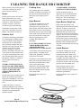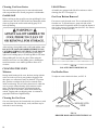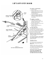
1
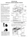
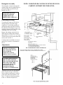
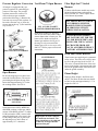
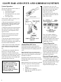
24”, 30”, 36”, 48” and 60” Range Models 36” and 48” Cooktop Models Your exact model may not be pictured. INSTALLER: PLEASE LEAVE THIS MANUAL WITH THE RANGE FOR INSPECTION AND SERVICE USE. CONSUMER: PLEASE RETAIN THIS MANUAL FOR FUTURE REFERENCE. Before using your range or cooktop, read this book carefully. Record the model and serial numbers. • It is intended to help you operate and maintain your new range or cooktop properly. You will find them on a rating plate under the cooking surfaces. Depending on the size and features of your range, the label may be under the griddle/grill or on the right inside cooktop wall beneath the burner pans. • Keep it handy for answers to your questions. • If you have questions, write to [email protected] or call 1-800-251-7224 to speak with a factory Parts & Service representative. Mon-Thurs: 8am-5pm, Fri: 8am-4pm (Eastern Time) • Corporate office address: FiveStar Range Division Brown Stove Works, Inc. P.O. Box 2490 Cleveland, TN 37320 Model Number Manufacturing Type Number Serial Number Record and use these numbers in any correspondence or service calls concerning your range. CONTENTS Accessories . . . . . . . . . . . . . . . . . . . . 30-31 Adjustments . . . . . . . . . . . . . . . . . . . . . 6-7 Aluminum Foil . . . . . . . . . . . . . . . . . 11, 14 Backguard Assembly. . . . . . . . . . . . . . . . 6 Baking. . . . . . . . . . . . . . . . . . . . . . . . 14-15 Before Using . . . . . . . . . . . . . . . . . . . . . 13 Broiler Assembly Removal . . . . . . . . . . 14 Broiling . . . . . . . . . . . . . . . . . . . . . . . . . . 16 Burners. . . . . . . . . . . . . . . . . . . . . . . . . . . 13 Cleaning Your Range . . . . . . . . . . . . 17-21 Convection Oven Cooking . . . . . . . . 14-15 Electronic Ignition . . . . . . . . . . . . . . . . . . 9 Energy-Saving Tips . . . . . . . . . . . . . . . 15 FiveStar Contact Info . . . . . . . . . . . . . . . 2 Gas and Electric Connections . . . . . . . 3-6 General Information . . . . . . . . . . . . . 12-16 Glow Bar Information . . . . . . . . . . . . . . . 8 Griddle/Grill . . . . . . . . . . . . . . . . . . . . . .11 Griddle Accessory . . . . . . . . . . . . . . . . . 30 Installation Instructions . . . . . . . . . . . . 3-6 Lift-Off Oven Doors . . . . . . . . . . . . . . . . . 19 Model Identification . . . . . . . . . . . . . . 21-22 Moisture . . . . . . . . . . . . . . . . . . . . . . . 18, 32 Operation of Range . . . . . . . . . . . . . . . 12-16 Oven Racks . . . . . . . . . . . . . . . . . . . . . . . . 13 Oven Rack Positions . . . . . . . . . . . . . . . . . 15 Oven Safety Tips . . . . . . . . . . . . . . . . 10-11 Oven Use . . . . . . . . . . . . . . . . . . . . . . . 13-16 Positioning/Leveling . . . . . . . . . . . . . . . 3, 6 Power Outage . . . . . . . . . . . . . . . . . . . . . . 12 Repair Parts . . . . . . . . . . . . . . . . . . . . . . . 32 Safety Instructions . . . . . . . . . . . . . . . . 10-11 Self-Cleaning Instructions . . . . . . . . . . 20-21 Service . . . . . . . . . . . . . . . . . . . . . . . . . . . .32 Top Burners . . . . . . . . . . . . . . . . . . . . . . . 12 Trouble Shooting Guide . . . . . . . . . . . . . . 32 Unpacking . . . . . . . . . . . . . . . . . . . . . . . . . 3 Wall Clearances . . . . . . . . . . . . . . . . . . . 3-6 Warranty . . . . . . . . . . . . . . . . . . Back Cover Wiring Diagrams . . . . . . . . . . . . . . . . . 23-29 • ALL RANGES CAN TIP • INJURY COULD RESULT • INSTALL ANTI-TIP BRACKET 24”, 30”, 36” ranges only • SEE INSTRUCTIONS IF RANGE IS RELOCATED, ANTI-TIP BRACKET MUST BE REMOVED AND REINSTALLED IN NEW LOCATION. 2 If you receive a damaged range… Immediately contact the dealer or builder who sold you the range. FIVESTAR INSTALLATION INSTRUCTIONS Please read these instructions before attempting to install this range. Unpacking Check the range carton for visible damage. If there is damage or even creases in the carton contact the carrier, request and inspection, and file the appropriate freight claim. Do not refuse shipment. Responsibility for shipping damage is with the carrier and the dealer or end user. Cut the shipping straps then carefully lift the carton up from the range. This will help eliminate possible damage to the backguard that is packed in the top of the range carton. GAS CONNECTION AREA Remove, unwrap, and temporarily lay aside any parts that are not attached to the range. Make sure no parts are left in the carton for accidental disposal. Carefully inspect the range for damage. The open burners are held in place with a shipping screw to protect them while in transit. These screws are to be removed and discarded to give proper top burner operation and allow easy removal for cleaning. FOR ISLAND CABINET INSTALLATION, THE MINIMUM ALLOWABLE HORIZONTAL CABINET REAR CLEARANCE BEHIND THE APPLIANCE IS 4”. 3 WALL CLEARANCES GAS AND ELECTRIC CONNECTIONS Wall Clearances All units must be installed in accordance with minimum side wall clearances and clearances extended vertically above the cooking top. See FIG. 1 and FIG. 6 for illustrations. This unit may not be installed directly adjacent to sidewalls, tall cabinets, tall appliances, or other side vertical surfaces above the 36” cooking surface height. There must be a minimum of 6” vertical side clearance to either side of the appliance extending from the cooking surface to 18” above to a maximum wall cabinet depth of 13” (See FIG. 1 and FIG. 6). Combustible surfaces must be a minimum of 40” above the unit’s top cooking surface for the full width of the appliance if a range hood is not used. If a hood is used we recommend installation approximately 30” from the bottom of the hood to the top cooking surface (top of hood should be 7’ from the floor). ANY OPENINGS IN THE WALL BEHIND THE UNIT AND IN THE FLOOR UNDER THE RANGE MUST BE SEALED. FiveStar hoods may be installed from 24” to 30” above the cooking surface. A minimum of 28” is required when a FiveStar backsplash with warming shelves is used. Gas and Electric Connections Gas Connections (All Units) NOTE TO MASSACHUSETTS APPLIANCE DEALERS: Be sure this document is included in all gas range appliances sold to consumers in the state of Massachusetts. 4 NOTICE: Massachusetts law requires the following: • Appliances must be installed by a licensed plumber or gas fitter. • Appliances must be connected with three (3) foot (36” maximum length) flexible gas connector. • A “T” handle type manual gas valve in the gas supply line to the appliance is required. Plug in the electric power supply cord and make certain that the gas stub-out is prepared properly for the gas connection prior to moving the range into place. The gas supply line must be at least the same size or greater than the inlet line of the range. All FiveStar ranges use a ½” NPT inlet. Check any installer-supplied intake pipes and fittings visually and blow them out with compressed air to clear any dirt particles, threading chips, or other foreign matter before installing in a service line. The unit should be connected to a supply line with ½ inch black iron pipe or a certified flexible connector (See FIG. 3, 4, and 5). For USA installations, flexible connectors must comply with ANSI Z21.69 (latest edition). For Canadian installations, comply with CAN/CGA-6.16 (latest edition revision) with suitable strain reliefs. Manifold pressure should be checked with a manometer. For natural gas 4” wcp is required with open burners and 5” wcp is required with sealed burners. For LP gas 10” wcp is required. The incoming line pressure must be at least 1” wcp higher (but no more than 14” wcp) than manifold pressure. (a) The appliance and its individual shut-off valve must be disconnected from the gas supply piping system during any pressure testing of that system at test pressures in excess of ½ psig (3.5 kPa). (b) The appliance must be isolated from the gas supply piping system by closing its individual manual shut-off valve during any pressure testing of the gas supply piping system at test pressures equal to or less than ½ psig (3.5 kPa). We suggest that you have the dealer from whom you purchased your new unit install it or have the dealer arrange with a local plumber to make the installation. Installation must conform to local codes. In the absence of local codes, the installation must conform to the National Fuel Gas Code, ANSI Z223.1 (latest edition) in the USA. Canadian installations must conform to CAN 1-B149.1 or .2. To prevent gas leaks, use an approved sealing compound, which is resistant to liquefied petroleum gases, on all threaded connections. All-gas models come equipped with a three-wire (two conductors with ground) supply cord. Dual fuel ranges are not supplied with a range connection cord. The unit must be electrically grounded and installed in accordance with local codes. In the absence of local codes the installation must comply with ANSI/NFPA 70 (latest edition) in the USA and C22.1 (latest edition) in Canada. INSTALLER: INFORM THE CONSUMER OF THE LOCATION OF THE SHUT-OFF VALVE. BEFORE PLACING THE RANGE IN OPERATION CHECK FOR GAS LEAKS WITH A SOAPY WATER SOLUTION. DO NOT USE AN OPEN FLAME TO CHECK FOR LEAKS. NOTE: THESE INSTALLATION INSTRUCTIONS SHOULD REMAIN WITH THE UNIT FOR FUTURE REFERENCE. Connecting the Range to Gas Shut off the main gas supply valve before disconnecting the old range and leave it off until new hookup has been completed. Do not forget to relight the pilot on other gas appliances when you turn the gas back on. Because hard piping restricts movement of the range, the use of an AGAcertified flexible metal appliance connector is recommended unless local codes require a hard-piped connection. When codes require hard piping, piping must be recessed into or enter through the rear wall (See FIG. 1). Openings are provided in the back cover for through the wall piping. For sealed burner models, the nipple provided (See FIG. 4) must be removed and replaced with piping as illustrated in FIG. 5. Never use an old connector when installing a new range. If the hard piping method is used, you must carefully align the pipe; the range cannot be moved after the connection is made. To prevent gas leaks, put pipe joint compound on, or wrap pipe thread with Teflon® tape all around male (external) pipe threads. 5. When all connections have been made, make sure all range controls are in the OFF position and turn on the main gas supply valve. Use a liquid leak detector at all joints and connections to check for leaks in the system. 1. Install a manual gas shut-off valve in the gas line in an easily accessed location outside of the range. Make sure everyone operating the range knows where and how to shut off the gas supply to the range. CAUTION: DO NOT USE A FLAME TO CHECK FOR GAS LEAKS. 2. Install male ½” flare union adapter to the ½” NPT internal thread at inlet of the regulator. Use a backup wrench on the regulator fitting to avoid damage. 3. Install male ½” or ¾” flare union adapter to the NPT internal thread of the manual shut-off valve, taking care to back-up the shut-off valve to keep it from turning. 4. Connect flexible metal appliance connector to the adapter on the range. Position the range to permit connection at the shut-off valve or vice versa. When using test pressures greater than ½ psig to pressure test the gas supply system of the residence, disconnect the range and individual shut-off valve from the gas supply piping. When using test pressures of ½ psig or less to test the gas supply system, simply isolate the range from the gas supply system by closing the individual shut-off valve. Open Burners 5 Backguard Assembly The backguard, located in the top pack with the range, must be installed prior to placing the range in position for gas hookup. See FIG. 7. NOTE: COOKTOPS DO NOT HAVE LEVELING LEGS. CABINET SUPPORT MUST BE LEVEL. NEVER BLOCK THE FLOW OF AIR FOR COMBUSTION OR VENTILTION. SEE FIG. 2. Positioning/Leveling To position the range use a lift jack or enough manpower to lift the range completely. Avoid sliding, pushing, or pulling the range because this increases the possibility of bending the legs or the coupling connectors and could also result in damage to the floor covering. Ranges and cooktops must be level to obtain proper cooking results. Ranges adjust from 35 7/8” to 37 7/8” or 2” max. All units must be level front-to-back and side-to-side. See FIG. 2. Cooktops must be installed in a cut-out and on a level surface, as illustrated in FIG. 6. Adjustments ALL ADJUSTMENTS AND/OR CONVERSIONS MUST BE MADE BY THE INSTALLER OR SERVICING UTILITY DURING INSTALLATION. SEALED BURNER MODELS ARE FACTORY SET FOR THE GAS FOR WHICH THEY ARE TO BE USED. THEY CANNOT BE CHANGED FROM ONE GAS TO ANOTHER WITHOUT FACTORY AUTHORIZATION. Appliances are set for use with Natural gas or Propane (LP) gas. The factory orifice setting is indicated by a second prefix letter in the model number. The letter “T” indicates Natural gas setting. Letter “P” indicates Propane (LP). 6 FOR ISLAND CABINET INSTALLATION, THE MINIMUM ALLOWABLE HORIZONTAL CABINET REAR CLEARANCE BEHIND THE APPLIANCE IS 4”. Pressure Regulator Conversion Vari-Flame™ Open Burners All ranges are equipped with a gas pressure regulator for controlling gas pressure in the range. The pressure regulator must not be removed. To convert from one gas to another, perform the following: (1) Remove the convertor cap on top of the regulator. (2) Invert the convertor cap, or invert the selector pin on the cap. (3) Re-install the cap. See FIG. 8. FIG. 8 PRESSURE REGULATOR CONVERSION Ultra High-Low™ Sealed Burners FiveStar sealed burner models may not be adjusted without factory authorization. Please call 800-251-7224 to inquire about sealed burner adjustments. FIG. 10 VARI-FLAME™ CENTER SIMMER BURNER Open burner models are equipped with at least one burner with a centersimmer feature that is factory set. The burner orifice hoods are black for Natural gas and brass for LP gas. If the range is to be converted from Natural gas to LP or vice versa, call 1800-251-7224 for proper orifices and instructions. FIG. 11 OPEN BURNER CONVERSION ALL ADJUSTMENTS AND/OR CONVERSIONS MUST BE MADE BY THE INSTALLER OR SERVICING UTILITY DURING INSTALLATION. SEALED BURNER MODELS ARE FACTORY SET FOR THE GAS FOR WHICH THEY ARE TO BE USED. THEY CANNOT BE CHANGED FROM ONE GAS TO ANOTHER WITHOUT FACTORY AUTHORIZATION. Oven and Griddle Burners These burners are supplied gas by automatic safety valves. The safety valve orifice must be set for the gas being used. See FIG. 11. This valve is located at the base of the oven burner in the broiler compartment and at the base of the griddle burner in the burner box under the griddle assembly. Open Burners Flame Height Be sure the shipping screws have been removed from the burners. The correct positioning should place the top of the burner head approximately 3/8” below the cooking surface. See FIG. 9. Improper flame height is inefficient and unsafe. The flame on these burners should be blue in color and approximately 1¼” in height. See FIG. 12. FIG. 9 TOP BURNER LOCATION Open burners have LOW, MEDIUM, and HIGH positions. Adjust gas and air mixture in the HIGH position. To adjust LOW turn knob to LOW, remove knob and while holding the valve stem in the LOW setting with a pair of pliers turn the adjusting screw until a flame of approximately 1/8” is obtained. High flames on surface burners are inefficient and unsafe. The flame should always be adjusted so that it is no larger than the bottom of the pan. FIG. 12 7 GLOW BAR AND OVEN AND GRIDDLE IGNITION • To close the valve, use a flat screwdriver to twist the valve stems fully clockwise so the slot aligns side to side as shown in the underside view below. System Operation The glow bar ignition system consists of four main components. 1. The thermostat control 2. The glow bar ignitor 3. The automatic valve (also called the safety valve) 4. The manual valve • To open the valve, turn the stem fully counter-clockwise so the slot aligns front to back. The thermostat, ignitor, and safety valve are wired in a series circuit. • When the thermostat knob is turned to a selected setting, electrical contacts in the thermostat close applying power to the series ignition circuit. • With power applied, the ignitor begins to heat. Electrical resistance in the ignitor will decrease as the temperature of the ignitor increases. • Electrical current in the series circuit increases in proportion to the drop in ignitor resistance. • The glow bar ignitor limits the electrical current in the circuit to 3.3 to 3.6 amps. The surface temperature of the ignitor will be between 1800° and 2500°F. • When electrical current has reached the proper amperage, the automatic safety valve will open, releasing main burner gas. • The ignitor stays energized while the burner is lit. Once the selected temperature is reached, the thermostat contacts will open and remove power from the ignition circuit. The automatic safety valve will close after a few seconds, and the burner flame will go out. ELECTRICAL POWER IS REQUIRED TO OPERATE COOKING SECTIONS WITH GLOW BAR IGNITION. THE OVEN AND GRIDDLE BURNER(S) CANNOT BE MADE TO OPERATE DURING A POWER FAILURE. 8 FIG. 14 CONTROL PANEL UNDERSIDE FIG. 13 SERIES IGNITOR/VALVE CIRCUIT Manual Shut-Off Valves Each cooking section on the range that is operated by glow bar ignition (gas oven, etc) is under the control of a manual gas shut-off valve. Manual shut-off valves are located on the underside of the control panel. Open the oven door to access the slotted valve stems with a flat blade screwdriver. Note: On FiveStar cooktops, a rectangular hole is located on the underside of the control panel. Reach up through this hole with the screwdriver in order to access the griddle shut-off valve. Control Operation Thermostat controls for sections with glow bar ignition operate as usual. Lightly press in the control knob and turn counter-clockwise to the desired temperature setting. An indicator light will illuminate next to the control knob whenever the thermostat calls for heat. Electrical Requirements The differing electric systems on all Depending on the particular features of your FiveStar range, there may be one, two, or three “-7” FiveStar range require more power than standard ranges. Refer to shut-off valves. the range rating plate for the range’s Manual shut-off valves will always be ordered total amp rating and wiring from left to right in the following manner: diagrams shown on pages 23-29. 1. Gas oven (left side on dual oven models) 2. Griddle/Grill (if equipped) 3. Right gas oven (models 510 and 531, right side door) Electronic Ignition Ranges and cooktops have top ignitor electrodes. When a top burner knob is turned to the LITE position, electrodes will spark at a rate of approximately 1½ pulses (sparks) per second. On sealed burner models, the sparking will stop once the burner has ignited. On open burner models, rotate the knob slightly clockwise to stop sparking once lit. In the event of a power failure you may need to light the top burners with a match. Do so by holding a lit match near the surface burner and turning the knob counterclockwise to the LITE position. Spark Modules The heart of an electronic spark system is the module that is located either in the burner box, at the bottom of the appliance, or behind the service access panel on electric oven models. There is sufficient wiring to withdraw the module assembly to check the connections, make repairs or replacement. If sparking does not occur when the top burner control is on, see page 32 for troubleshooting tips. Wiring Diagrams DO NOT ATTEMPT TO SERVICE THE RANGE YOURSELF. NOTE: THESE INSTALLATION INSTRUCTIONS SHOULD REMAIN WITH THE UNIT FOR FUTURE REFERENCE. Wiring diagrams are located in this Use and Care manual (pages 23 to 29). One is also located behind the control panel near the griddle/grill knob or on the back of the access panel beneath the electric oven, depending on the model. NOTE: Burner rates specified on the rating plate of the range apply for elevations up to 2,000 feet above sea level. For locations where altitudes are higher than 2,000 feet, the BTU rated input should be reduced four percent for each 1,000 feet higher than 2,000 feet above sea level. If this adjustment is necessary, contact a qualified service technician. 9 SAFETY INSTRUCTIONS Read all instructions before using this appliance. Many accidents occur in the home. Most of these could be prevented with care and judgment. Use this appliance only for its intended use as described in this manual. When using appliances, basic safety precautions should be observed, including the following: Never allow children to play with the range controls. The range and pans on it can be hot. Do not allow anyone to climb on the range or use it or the doors for stepping, leaning, or sitting. Possible hazards or injuries may result. It is recommended that items not be stored on, in, or above the range. WARNING!!! All ranges can tip and injury can result. To prevent accidental tipping of the range, attach it to the wall or floor. See FIG. 2 on page 3. Be sure your appliance is properly installed and grounded by a qualified technician in accordance with the provided installation instructions. Do not attempt to repair or replace any part of your range yourself unless specifically recommended in this manual. All other servicing should be referred to a qualified technician. BEFORE PERFORMING ANY SERVICE, DISCONNECT THE RANGE POWER SUPPLY AT THE HOUSEHOLD DISTRIBUTION PANEL BY REMOVING THE FUSE OR SWITCHING OFF THE CIRCUIT BREAKER. When preparing your meals a great deal of heat is generated, and consequently some parts of the range will become HOT. Consider this in choosing the location for your range. Do not leave children unattended near the range when it is in use or while the surfaces are still hot from use. They should never be allowed to sit or stand on any part of the appliance. Never allow children to play in the kitchen around the range. CAUTION: ITEMS OF INTEREST TO CHILDREN SHOULD NOT BE STORED IN CABINETS ABOVE THE RANGE. A range hood that projects horizontally at least 5” beyond the bottom of the cabinets is recommended. Keep hood and grease filters clean to maintain good venting and to avoid grease fires. WARNING!!! Never use this appliance as a space heater or to heat or warm the room. Doing so may result in carbon monoxide poisoning and overheating of the oven and valve components. Never wear loose-fitting or hanging garments while using the appliance. Flammable materials could be ignited if brought in contact with hot surfaces with open flames and may cause severe burns. Use only dry pot holders. Moist or damp pot holders on hot surfaces may result in burns from steam. Do not let pot holders touch hot surfaces of the range. Do not use a towel or other bulky cloth as a pot holder. 10 Due to potential hazard do not use the oven or broiler space for storage. The top of the range should never be used for storage either. Flammable items can catch fire and plastic items may ignite or melt. Do not let cooking grease or other flammable materials accumulate in or near the range. Do not use water on grease fires. Never pick up a flaming pan. Smother flaming pan on surface unit by covering pan completely with well-fitting lid, cookie sheet, or flat tray. Flaming grease outside a pan can be put out by covering with baking soda or, if available, a multipurpose dry chemical or foam type fire extinguisher. EACH HOUSEHOLD SHOULD HAVE AN APPROPRIATE FIRE EXTINGUISHER FOR USE IN THE EVENT OF A HOUSE FIRE. DO NOT TOUCH BURNERS, BURNER GRATES, OR INTERIOR SURFACE OF OVEN. These surfaces may be hot enough to burn even though they appear to be cool. During and immediately after use do not touch or let clothing or other flammable materials contact any hot surfaces or any interior area of the oven. Allow sufficient time for cooling. Potentially hot surfaces include the cooking surface and areas facing the cooking surface, oven vent opening, and crevices around the oven door. Remember: The inside surface of the oven door may be hot when the door is opened. Oven Do not bake in a gas oven or use a broiler pan with excess grease buildup. Be careful when handling the broiler pan, especially when hot. Grease left in the pan can catch fire if the oven is used without removing the grease from the broiler pan. Keep oven free from grease buildup. Never use ammonia in an oven that is warmer than room temperature and always have direct ventilation. Stand away from the range when opening the oven door. Hot air or rising steam can cause burns to hands, face, and/or eyes. WARNING!!! Never cover any slots, holes, or passages in the oven bottom or cover an entire rack with aluminum foil or other materials. Doing so blocks air flow through the oven and may cause carbon monoxide poisoning. Aluminum foil linings may also trap heat, causing a fire hazard. When replacing an oven light bulb, be sure the oven is cool. Disconnect power to the range, and use a dry cloth to handle the bulb. Do not heat unopened food containers in the oven. Pressure could build up and the container could burst causing injury. Place oven rack in desired position while oven is cool. If rack must be handled when hot, use a pot holder. Pulling out the oven rack to the stop position is a convenience in lifting heavy goods. It is also a precaution against burns from touching hot surfaces of the door or oven walls. Always turn utensil handles to the side or back of the range to avoid accidental bumping and to keep out of reach of children. When using cooking or roasting bags in the oven, follow the manufacturer’s directions. Do not use your oven to dry newspapers or any other flammable materials. Surface Cooking Use proper pan size. Select utensils with flat bottoms large enough to cover the burner. The use of undersized utensils in which flame wraps the side of the utensil does not heat the contents faster; it only scorches the outside of the pot or pan, making clean up more difficult. Adjust the top burner knob to select a flame size to cover just the bottom of the pan or pot. Surface areas near burners may become hot enough to cause burns. During and immediately after use, do not touch areas near burners until they have had sufficient time to cool. Never leave top burners on and unattended. Boilovers cause smoking and greasy spillovers may catch on fire. Do not use aluminum foil to line burner pans or inside oven except as described in this manual. Misuse could result in fire hazard or damage to the range. Only certain types of glass, glass/ceramic earthenware, or other glazed containers are suitable for range top use. Others may break because of the sudden change in temperature. Always refer to specific cookware instructions. An overhead ventilation hood that directs air in a downward manner toward the appliance is not to be installed with a FiveStar. Ventilation hoods that direct air toward a gas range may cause ignition or combustion problems with a gas cooking appliance resulting in personal injury or unintended operation. Always turn surface burner to OFF before removing cookware. To avoid the possibility of a burn always make certain that the controls for all top burners are in OFF position and all burner pans are cool before attempting to remove the grates, burner caps, burner pans, or burners. Do not put removable surface burners in a dishwasher. Be attentive to frying foods at all temperatures. Foods for frying should be as dry as possible. Frost or ice on frozen foods or moisture on fresh foods can cause hot fat or oil to bubble over sides of pan very quickly. Use only enough fat or oil for effective shallow or deep frying. Filling the pan with excess fat can cause spillovers when food is added. If a combination of oils or fats will be used in frying, stir together before heating or as fats melt. Always heat fat slowly and monitor as it heats. Use a deep fat thermometer whenever possible to prevent overheating fat or oil beyond the smoking point. EACH HOUSEHOLD SHOULD HAVE AN APPROPRIATE FIRE EXTINGUISHER FOR USE IN THE EVENT OF A HOUSE FIRE. 11 GENERAL INFORMATION Final adjustments and/or conversions from one gas to another are not covered under the manufacturer’s warranty. Contact your dealer for the name of a local authorized service agency. If none is available, contact FiveStar’s factory Parts & Service Department by calling 1-800-2517224. Telephone hours are from 8:00am to 5:00pm, Eastern Time, Monday through Thursday, and from 8:00am to 4:00pm on Fridays. You may also send an email to [email protected] for help finding a service professional near you. SPECIFICATIONS Ranges may be installed directly against rear walls and side base cabinets. They may not be installed directly against side tall cabinets, sidewalls, or tall appliances. See “Wall Clearances” on page 4. Electrical requirements All-Gas Ranges and Cooktops: 120 volts, 60 Hz, 15 amps. Dual Fuel Ranges: 120/240 volts, 60 Hz, 35 amps. Natural Gas: 4.0” WC open burner, 5.0” WC sealed burner. Propane: 10.0” WC (both types of burners) Residential exhaust vent hoods may be installed above the range. Provide properly sized exhaust fans for efficient operation. No sprinklers are required. If this range is removed for any reason (service, cleaning, etc), it must be replaced as outlined in the installation instructions before placing the range back in operation. Field Adjustments All ranges are tested before leaving the factory. Field adjustments are necessary for proper operation. The range must be installed and adjusted by a qualified technician. 12 make a clicking sound. This clicking is the electrodes beneath the top of each pair of burners. After lighting, turn the knob clockwise to desired heat setting. This turns off the electricity to the electrodes. If the knob is turned to LITE and no clicking sound occurs, turn the knob off and check the electrical connection, fuse, or circuit breaker if necessary. NEVER LEAVE THE KNOB IN THE LITE POSITION AFTER THE BURNER HAS BEEN LIT. Doing so will shorten the life of the electronic system. DO NOT ATTEMPT TO SERVICE THE RANGE YOURSELF. NOTE: THESE INSTRUCTIONS SHOULD REMAIN WITH THE UNIT FOR FUTURE REFERENCE. TOP BURNERS All top burners have electronic ignition. Open burners have manual ignitors, while sealed burners feature flame sensing ignitors. When a top burner knob is turned to the LITE position, electrodes will spark at a rate of approximately 1½ pulses (sparks) per second. On sealed burner models, the sparking will stop once the burner has ignited. For open burner models, the sparking will not stop until knob is rotated clockwise off of the LITE position. In the event of a power failure, you may light the top burners with a match. Hold lit match near the surface burner and turn the knob counterclockwise to the LITE position. Once the burner is lit, operate normally. Open Burners To light the top open burners, push the knob in and fully turn the knob counterclockwise to the LITE setting. When the knob is set to LITE, the burner will Sealed Burners To light the top sealed burners, push the knob in and turn counter-clockwise slightly to the LITE position. A clicking sound will begin when the knob is set to LITE, but the sound will stop after ignition. After lighting, continue turning to desired setting. Oven and Griddle Burners These concealed burners use automatic ignitors. The griddle and oven control dials do not need to be set to a LITE position to light the burners. Simply turn the control dial to the desired setting. IF THE OVEN OR GRIDDLE BURNER DOES NOT IGNITE WITHIN 90 SECONDS OF TURNING ON THE OVEN CONTROL DIAL, TURN THE OVEN OR GRIDDLE BACK OFF. DO NOT ATTEMPT TO USE THE OVEN OR GRIDDLE. CONTACT A QUALIFIED SERVICE TECHNICIAN TO DETERMINE THE SOURCE OF THE PROBLEM. Before Using the Range or Cooktop New units are wiped clean with solvents at the factory to remove any traces of dirt and grease. Each range and cooktop is then coated with a thin film of mineral oil. Some stainless steel parts may have a plastic protective wrapper which must be removed before using the range. Before starting too cook the range should be washed thoroughly with hot, soapy water to remove film residue and any dust or debris from installation. Rinse and wipe dry. If the range contains an oven or ovens, remove and unwrap all loose pieces from inside the oven(s) and/or broiler area. If the unit contains a gas oven, remove the included broiler pan in lower broiler area. Remove and discard the plastic and wash and dry the pan thoroughly before replacing it in broiler cavity. If the unit contains an electric oven, remove the broiler pan from inside the oven. Wash and dry the piece and store it for later use. If the unit contains an oven or ovens, turn on each oven to 400°F for approximately one hour. This burns off the binder from the insulation and prepares your oven(s) for normal use. There may be a slight odor. Once the unit is installed as outlined in the Installation Instructions (pages 3-6), it is important that the air supply to the unit remains open. The oven air supply comes through the front floor area under the range. The surface burners get air from the area below the control panel. See FIG. 2 on page 3. THESE AREAS MUST REMAIN OPEN AND UNOBSTRUCTED. Cooking Utensils Most cooking utensils are suitable for use on the FiveStar, and it is not necessary to replace your present domestic utensils with commercial cookware. Cookware should be in good condition and free of excessive dents or bulging on the bottom to provide maximum performance and convenience. Use of Oven Preheat oven if necessary or desired. While several variables affect preheat time, the general recommendations are: Electric Oven: 12-15 minutes to 350°F. Gas Oven: 8-10 minutes to reach 350°F. Preheat time will vary. Allow at least one inch space around oven pans and the oven walls. Correct pan placement allows air circulation for proper baking and browning. Do not place pans in the oven directly over one another. Stagger the pans so that air flow will not be inhibited. See FIG. 15. Always keep oven vent ducts unobstructed. Oven Temperature Selection It is important to select a proper temperature setting. Never set the oven dial to a higher degree than needed with the intention of lowering the setting at a later time. This will not speed up the action. Doing this can actually cause the oven to cycle more slowly, making the temperatures vary and cooking results to be unsatisfactory. The oven will maintain an even temperature if the oven control dial is set directly from OFF to the desired temperature. Temperature ranges from 140°F to 200°F are for “low temp” warming. These temperature settings are used to keep food at serving temperature. The temperature range from 250°F to 550°F is usually used for normal baking. The general baking range is from 350°F to 425°F. Oven Racks All convection ovens (gas and electric) contain three oven racks, while gas ovens without convection contain two oven racks. The oven racks should be arranged before the oven knob is turned to the ON position. Place the racks so the food will be centered in the oven. When more than one utensil is used, be sure to stagger them allowing space between each one (See FIG. 15). Do not allow the utensils to touch any part of the oven, especially the glass window. It is best to use only two racks at a time and place food so one utensil is not directly over another. Oven Rack Removal First make sure oven and rack have cooled sufficiently for handling. If still warm or hot, use oven mitts. FIG. 15 PAN POSITIONING–TOP RACK (LEFT), BOTTOM RACK (RIGHT) Pull the oven rack forward and lift up on the front of the rack so it will clear the rack keeper. To replace the oven rack, guide the angled rear portion of the rack under the rack keeper and slide the rack to the rear. 13 Gas Broiler Assembly Baking Each gas oven has a gas broiler below the oven. A broil pan and grill are held in place by a uniquely fashioned broiler rack (See FIG. 16). To open the broiler, gently lift up on the broiler door handle and pull forward. Use an oven mitt to grasp the broiler pan and gently pull forward. It will reach a temporary stop. Continue to pull forward and the broiler rack will pull out exposing the broiler pan surface. When baking, follow the recipe instructions. Use correct ingredients, measuring them carefully, and use the correct type and size utensil suggested in the recipe. Follow recipe cooking times and temperatures, using them as a guide only. Use tested recipes from reliable sources. FIG.16 GAS BROILER ASSEMBLY The pan and grill may be removed from the boiler rack by lifting up on the front of the broiler pan so it will clear the pan “keeper.” Then using oven mitts to protect hands, pull forward slightly to remove pan and grill from the broiler rack. The broiler rack may be removed in the same manner as removing an oven rack. To return the pan and grill to the broiler rack, pull the broiler rack to the stop position and insert the pan into the recessed section of the broiler rack. Make certain the pan “keeper” pins clear the front edge of the broiler rack. Slide the pan and grill in place under the pan retainers. Push the pan and rack back to position and close the broiler door. Aluminum Foil in Oven and Broiler Aluminum foil is a cause of many range fires. Make certain that vents or air openings are not covered by foil. If the vents located along the sides of the oven bottom are blocked, poor cooking and burner performance will result. Never cover a rack with aluminum foil. 14 Arrange oven racks before turning on the oven. Allow about 1 to 1½” of space between the oven side walls and utensils for proper air circulation. When baking foods in more than one utensil, place them on opposite corners of the oven rack. Stagger utensils when baking on separate racks so that one utensil does not shield another (See FIG. 15 on page 13). To conserve energy, avoid frequent or prolonged door openings. At the end of cooking, turn oven off before removing food. Always test for doneness (fingertip, toothpick, etc). Do not rely on time or brownness as sole indicators. Remember to preheat as indicated. Avoid frequent opening of the oven during preheating and baking, as this causes heat loss and varying temperature. When baking cakes in glass baking dishes, lower the oven temperature 25 degrees to prevent uneven browning. Also when using glass bakeware, increase the preheat time to encourage exact stabilization of the oven’s temperature. To do so, allow 20 minutes for temperatures up to 350°F and 30 minutes for temperatures up to 425°F. Avoid opening the oven door as much as possible. Use good quality baking utensils and the size recommended in the recipe. Dull, dark, enameled, or glass utensils will generally produce a brown, crisp crust. Shiny metal utensils produce a light, golden crust. Frozen pies in shiny aluminum pans should be baked on a cookie sheet or removed to a dull or glass pan prior to baking. Do not be concerned if condensation occurs on the oven window. This is normal and usually disappears after the oven has operated for a short time. Convection Oven Models Convection oven ranges offer the choice of normal radiant baking and roasting or convection baking and roasting. The benefits of convection cooking are: More even baking and roasting. A general reduction in cooking time for most baked foods – up to 30% faster. The opportunity to reduce cooking temperature and stay within original cooking time. Operating the convection fan while preheating the oven will not reduce preheat time. The convection control is located on the control panel beside the control knobs and may be switched on anytime during the baking cycle, for complete control. CAUTION: DO NOT USE ALUMINUM FOIL TO LINE OVEN INTERIOR. USE BOTH HANDS AND OVEN MITTS WHEN HANDLING OVEN RACKS, BROILER PANS, BROILER RACKS, AND OVEN FLOORS. Convection Cooking on Multiple Racks For best results, bake foods on one rack at a time as described in this manual. However, very good results can be obtained when baking on multiple racks using the TurboFlow convection feature. The convection oven is suggested for multiple rack cooking, especially three rack cooking. For best results, stagger baking utensils as shown in FIG. 15 on page 13, and follow these suggestions: For two rack baking, leave one rack position empty between rack positions (in other words, use positions #2 and #4 or #1 and #3). use of cookie sheets. Baking times will be similar. For three rack baking, use positions #2, 3, and 4. Bread pans and cookie sheets should be placed lengthwise, front to back, in front of the convection fan for more even browning. Center food dishes in the oven. If more than one food item is being baked on multiple racks, stagger them for proper air circulation. Convection Baking of Frozen Convenience Foods Follow package recommendations for oven temperature, foil covering, and Most foods are baked on rack position #3 (see FIG. 17). For multiple rack baking, use racks #2 and #4. However, frozen pizzas should be placed on round pans or pizza stones and baked on rack positions #3 and #4 (see FIG. 17). FIG. 17 ELECTRIC OVEN INTERIOR (Gas convection ranges do not have elements in the oven cavity) ENERGY-SAVING TIPS Surface Cooking Cook fresh vegetables with a minimum amount of water in a covered pan. Monitor foods when bringing them to cooking temperature quickly at high heat. When food reaches cooking temperature, reduce heat immediately to lowest possible setting that will still allow for sufficient cooking. When boiling water heat only the amount needed. It is not economical to boil extra water. Use correct heat setting for cooking task: HI: Use to start cooking if desired. If time permits, use a lower heat to start. MED: Use for quick browning. LOW: Use to finish cooking most quantities, double-boil, or to cook small quantities normally. SIM: Use to simmer and maintain serving temperature of most foods. Oven Cooking Preheat oven if necessary or desired. Preheat time will vary. Always turn oven OFF before removing food. During baking, avoid opening the oven door. If the door must be opened, keep it open as briefly as possible. Cook complete oven meals instead of just one food item. Potatoes, other vegetables, and some desserts will cook together with a main dish casserole, meat loaf, chicken, or roast. Choose foods that cook at the same temperature and in approximately the same amount of time. Use residual heat in the oven whenever possible to finish cooking dishes. Add rolls or precooked desserts to a warm oven, using residual heat to warm them. 15 Broiling Broiling times vary depending on a meat’s thickness, fat content, and personal taste. Always be careful when handling hot broiler pans. Use both hands and oven mitts when handling. Serious injury can result due to spillage of hot grease. Gas Broiling Never leave a dirty broiler pan in place. Always clean it and return it to the broiler assembly. Unauthorized broiler pan substitutes should never be used. Excess fat should be trimmed from meats to eliminate the possibility of flame ups. The meat could be ruined or fire could occur, causing loss of property and potential bodily injury. Always broil with the oven door and broiler door closed. When broiling is completed, turn the dial to OFF, let the broiler cool completely, and remove the broiler pan temporarily for cleaning. NEVER USE THE GAS BROILER AREA FOR STORAGE. Electric Oven Broiling The electric broil element is located at the top of the electric oven cavity. For best results, follow these suggestions: Place oven rack in position #4 (See FIG. 17 on page 15) Turn the oven dial counter-clockwise to BROIL. Place food on roasting/broiler pan provided with the oven. After top broil element begins to glow red, place food in the oven. 16 Always broil with the oven door closed. The oven thermostat will maintain the temperature while food broils. The griddle/grill plate is pre-seasoned and ready to use. To reset the oven for baking, simply turn the dial clockwise to desired baking temperature. Broil element will switch off and the bake element will come on. Preheat griddle at 450°F for 12-15 minutes. Once preheated, turn dial to desired temperature. Broiling Tips Tender cuts of meat or marinated meats are best for broiling. For best results, steaks should be at least 1” thick. Thinner steaks should be pan broiled. Do not cover broiler grill with foil since this prevents fat drippings from draining into the bottom of the pan. To make cleaning easier, spray pan and grill with non-stick spray. Before broiling, remove excess fat from meat and score edges of fat (do not cut meat) to prevent meat from curling. Salt after cooking if desired. To prevent drying of fish or lean meat, brush melted butter or oil over surface before broiling. Foods that require turning should be turned only once during broiling. Use recipe directions as a guide to broil time. Reversible Griddle/Grill The griddle is equipped with a cast iron plate that is reversible for use as a grill. To flip the griddle to the grill side or vice versa, simply lift up the griddle by the front edge, flip over the plate, and place it back in the housing. Griddle Cooking Use liquid cooking oil, cooking sprays, or butter for eggs, pancakes, French toast, fish and sandwiches. This will help to reduce sticking. Remove food particles during cooking to make the clean up easier and to avoid including these particles in the cooked food. Do not use sharp objects to clean the griddle/grill, as these can scratch the cast iron surface. Direct the flow of grease to the center of the grease well. Do not over-heat the griddle. Turn it off when not in use, or lower heat between cooking loads. Griddle Cooking Guide Food Temperature Eggs Bacon French Toast Pancakes Fish Filets Hamburgers Steaks 250-300°F 325-350°F 375-400°F 375-400°F 350°F 350°F 350°F Use this chart as a guide only. Always use a meat thermometer to test for meat doneness. CLEANING THE RANGE OR COOKTOP Make certain all parts of the range are cool before cleaning. Be sure to replace all parts correctly. Knobs Pull forward to remove the control knobs. Wash with warm, soapy water. Do not use abrasive or harsh cleansers or scrub with abrasive materials. Abrasive action will scratch away the knob markings. If the knobs become loose on the valve stem, spread the valve stem slightly with a small screwdriver. Stainless Steel All stainless steel body parts should be wiped regularly with hot, soapy water or a liquid cleaner designed specifically for use with stainless steel. Solutions stronger than soap and water are rarely required. Never use steel wool, abrasive cloths, abrasive cleansers, or abrasive powders on stainless steel parts. If it is necessary to scrape stainless steel to remove encrusted materials, soak spot with hot damp cloths to loosen the material. Then use a wooden or nylon scraper to lift stuck-on materials. NEVER USE METAL KNIVES, SPATULAS, OR OTHER SHARP TOOLS TO SCRAPE STAINLESS STEEL. SCRATCHES ARE ALMOST IMPOSSIBLE TO REMOVE. Do not allow citrus or tomato juice to remain on a stainless steel surface. Wipe spills immediately. Citric acid will permanently discolor stainless steel. Cooktop Area Any cooktop spill-overs should be wiped up as quickly as possible. Use an oven mitt to protect hands from heat when removing the grate or grates. Open Burners To clean the cooktop area on your open burner model, first let the cooking surface cool. Remove all burner grates, and lift the fronts of the burner pans to remove them. Remove the burner and let it soak in hot, sudsy water. Most stains will then wipe off, but if not, scrub with a strong, nonabrasive cleaning pad or nylon scrubber. Rinse the burner thoroughly. IT IS VERY IMPORTANT THAT THE BURNER BE DRAINED AND DRIED BEFORE REPLACING IT IN THE RANGE. A wet burner will not allow the gas to ignite properly. A buildup of gas could result, potentially creating an explosion or fire hazard. If spills have seeped below the burner pans, remove the porcelain drip trays and either wash them in hot, soapy water or place them in the dishwasher. Dry thoroughly before replacing beneath the burner. The burner box bottom may be cleaned with a damp cloth. Do not put burner grates in a dishwasher. AVOID HARSH CLEANSERS AROUND ALUMINUM PARTS Do not use harsh cleaners or degreasers on or around functional parts (valves, controls, aluminum tubing, etc). This will damage or drastically reduce the life of the parts. Open Burner Drip Pans Below each open burner is an individual porcelain-enameled burner drip pan. To place or remove the pans, remove the shipping screws holding the burners in place (one center screw per burner at the burner support). These screws do not need to be replaced and may be discarded. Remove the burner to access the drip pan. Be sure the burner is cool before handling. These individual burner drip pans are dishwasher safe for easy cleaning. Sealed Burners To clean the cooktop area on your sealed burner model, first let the cooking surface cool. Remove all burner grates. With a damp, soapy rag or sponge, wipe the cooktop area around each burner to remove stuckon materials. Remove any food or dirt particles from the cooktop area. Remove burner caps for easier cleaning. Burner caps must be correctly reseated for proper ignition and burner performance. Do not put burner caps or grates in a dishwasher. A light coat of baby oil may be applied periodically to the stainless steel surfaces. This will help prevent moisture from penetrating the stainless surfaces. FIG. 18 SEALED BURNER BASE AND CAP 17 Cleaning Cast Iron Grates Lift-Off Doors The cast iron burner grates may be removed and cleaned with soap and hot water. Do not put grates in a dishwasher. All models are equipped with lift-off oven doors to aid in cleaning (See FIG. 19 on page 19). Griddle/Grill Before cooking on the reversible cast iron griddle/grill, rinse with hot water. DO NOT USE SOAP. Dry thoroughly with a clean rag. Prepare the surface with cooking spray or oil before preheating. Gas Oven Bottom Removal First remove racks from the oven. The oven bottom lifts up from the rear. To lift and remove, grasp each side of the oven bottom and lift upward from the rear until the bottom is clear. Lift to remove it from the front (See FIG. 20). Electric oven bottoms are not removable. After cooking, clean griddle with a stiff brush and hot water. DO NOT USE SOAP OR HARSH DETERGENTS ON CAST IRON SURFACE. NEVER PUT CAST IRON IN A DISHWASHER. Towel dry immediately and apply a light coat of cooking spray or oil while griddle is still warm. Store griddle/grill in a cool, dry place. When using the stainless steel cover over the griddle, place a folded paper towel between the cover and the griddle to allow air to circulate. CLEANING THE OVEN Moisture During initial heating of the oven, the heat mixing with the cooler air in the oven cavity may produce fogging of the door glass or a collection of water on the door. To prevent this, open the oven door for the first few seconds of the initial oven heating. This will allow the moist air within the oven to escape without forming visible moisture on the range. The amount of moisture will depend upon the humidity of the air and water content of the food being cooked. Fogging and even dripping water is common in geographic locations of high humidity. FIG. 20 GAS OVEN BOTTOM REMOVAL Gas Broiler Door To adjust or remove the broiler door, see FIG. 21 Cleaning the Gas Oven Gas oven interiors may be cleaned with oven cleaner or with soap and water. The oven door(s), racks, and floor may be removed for easier cleaning. FIG. 21 BROILER DOOR ADJUSTMENT/REMOVAL 18 LIFT-OFF OVEN DOOR To remove oven door(s) Open door fully. Rotate the Hinge Retainers into the locked position, as shown, over the hook located on the bottom side of each hinge quadrant. Lift the door slightly to clear the hinge slots, and pull straight out to clear hinge mechanism from main front opening. To replace oven door Insert hinges into front frame opening, locating the hinge slots on the front frame as shown. Rotate the Hinge Retainers back into the “open” position. Rotate the door to make sure it functions properly. To clean the door Use soap and water to wipe away spots and stains. Heavy splattering or spillovers may require cleaning with a mild abrasive cleaner. Do not allow food spills with high sugar or acid content (milk, tomatoes, pie filling, etc) to remain on the surface. They may cause discoloration even after cleaning. YOU MAY USE OVEN CLEANER IN GAS OVENS ONLY. Be sure to follow package directions. Outside of door Use soap and water to thoroughly clean the top, sides, and front of the oven. Rinse well. FIG. 19 LIFT-OFF DOOR MECHANISM Spillage of acidic foods or juices may cause discoloration and should be wiped up as quickly as possible. When surface is cool, clean and rinse spot. NEVER USE OVEN CLEANERS, CLEANSING POWDERS, OR HARSH ABRASIVES ON THE OUTSIDE OF THE OVEN DOOR. 19 CLEANING THE ELECTRIC OVEN Each FiveStar electric oven contains a self-clean cycle. These self-cleaning electric ovens clean with very high temperatures (well above cooking temperatures) which reduce soils to a fine powdered ash for easy clean up with a damp cloth. WARNING – During the selfcleaning cycle, the exterior of the range can become very hot to the touch. DO NOT leave small children unattended near the appliance while in self-clean. heavy smoke or fire when subjected to high temperatures. DO NOT allow food spills with high acid or sugar content to remain on the surface. These may cause dull spots even after cleaning. Clean any soil from the oven frame, the door liner outside the oven seal, and the small area at the front center of the oven bottom. These areas do not become hot enough to burn soil off. Clean with soap and water only. CAUTION – DO NOT line the oven with aluminum foil. This practice will destroy heat distribution during cleaning and cause the aluminum foil to melt to the oven finish creating permanent damage to the appliance. DO NOT use commercial oven cleaners or protective coatings in or around any part of the self-cleaning oven. DO NOT clean the oven door seal. The woven gasket is essential for a good seal. Care should be taken not to rub, damage, or remove the seal. FIG. 22 SELF-CLEAN OVEN INTERIOR Starting the Self-Clean Cycle Before pre-cleaning, always allow the oven to cool. Close the oven door. There is an interlock switch that senses when the door is fully closed. Turn the oven control knob counter-clockwise to the CLEAN position (until it stops). DO NOT ATTEMPT TO TURN THE OVEN KNOB CLOCKWISE TO THE CLEAN SETTING. THIS COULD CAUSE DAMAGE TO THE THER-MOSTAT AND WILL VOID THE WARRANTY. It is recommended that oven racks be removed before self-cleaning. The high cleaning temperatures could permanently discolor the bright finish. Once the oven dial has been set to CLEAN, push and hold the momentary door lock switch on the control panel. A faint buzzing sound is normal. Remove excess spillovers from the oven cavity prior to starting the selfclean cycle. To pre-clean, use hot soapy water and a cloth. Remove large spillovers, as they can cause While holding the switch in LOCK position, move the door lock handle to the left until it stops. 20 The complete self-cleaning cycle from door lock to unlock takes approximately 3 hours and 45 minutes. NOTE: During this cycle the convection fan and the griddle burner are inoperative. A remote timer controls the cleaning cycle and it is automatically reset when the door is unlocked at the end of the cleaning cycle. Indicator Lights Remove all utensils from inside the oven. These items cannot withstand cleaning temperatures. Release the LOCK switch. The oven is now cleaning. If the cleaning cycle is interrupted for any reason, wait three hours before restarting. This allows the remote timer to reset. Preparing Oven for SelfCleaning Wear rubber gloves when precleaning and when wiping up after the self-clean cycle. The oven indicator light is on anytime the oven control is in the ON position. It will cycle at knob setting or at the clean temperature, approximately 875°F. The DOOR LOCKED indicator light will come on only when the oven reaches 400°F or higher. The broil element brings the oven temperature to approximately 800°F. Smoke generated during initial heating is consumed by the broil element on its way to the vent. After approximately 30 minutes, the system will switch from broil to bake, and the temperature will rise to 875°F, cycling off and on for an additional 2 hours and 30 minutes. The system will then turn the oven off, and the oven signal light will go off. The oven will then begin to cool. After approximately 45 minutes, the DOOR LOCKED indicator light will go off, indicating that the oven temperature has dropped to approximately 400°F, and the door can be unlocked and opened. Follow instructions on page 21 to unlock the door after self-clean. To Unlock the Door After Self-Clean Keep the oven dial in CLEAN position. Push and hold the momentary door lock switch on the control panel while moving the door lock handle to the right until it stops. Turn the oven control knob to OFF position. NOTE: The oven door cannot be locked or unlocked unless the knob is in the CLEAN position. When the oven is COMPLETELY cool, wipe up the fine powdered ash with a clean damp cloth. STOPPING OR INTERRUPTING THE SELF-CLEANING CYCLE If it becomes necessary to stop or interrupt a self-cleaning cycle due to excessive smoke or fire, follow these steps: If the DOOR LOCKED indicator light is OFF: The oven temperature is below 400°F. Keep the oven control knob in CLEAN position. Push and hold the momentary door lock switch while moving the door lock handle to the right until it stops. Turn oven dial clockwise to OFF. The oven door may be opened and used normally. If the DOOR LOCKED indicator light is ON: The oven temperature is above 400°F. Turn the oven control clockwise to OFF position and wait for the oven to cool. When the DOOR LOCKED indicator light does not come back on when the oven knob is turned counter-clockwise to CLEAN, the door may be unlocked and opened. With the oven control in the CLEAN position, push and hold the momentary door lock switch while moving the door lock handle to the right until it stops. Turn the oven control clockwise to OFF. The oven door may be opened for normal operation or maintenance. CAUTION: DO NOT FORCE THE DOOR OPEN. THIS CAN DAMAGE THE DOOR LOCK MECHANISM. USE CAUTION WHEN OPENING THE DOOR AFTER STOPPING THE SELFCLEAN CYCLE. THE OVEN WILL STILL BE VERY HOT. CORRECT THE CONDITION WHICH CAUSED THE SMOKING, WAIT THREE HOURS, AND RESTART SELF-CLEAN. CONTROL PANEL DIAGRAMS 21 22 WIRING DIAGRAMS 23 24 25 26 27 28 Wiring Range Connection Cord (For Dual-Fuel Ranges Only) FIG. 24 FIG. 23 WARNING!!! THIS APPLIANCE MUST BE CONNECTED AS SHOWN IN FIG. 23 OR FIG. 24. IF A CORD IS UTILIZED IT MUST BE RATED AT 250 VOLTS, 40 AMPERES, AND CERTIFIED FOR USE ON HOUSEHOLD RANGES. 29 FIVESTAR ACCESSORIES Included Accessories Wok Ring Stainless Steel Griddle Cover All Sealed burner model ranges and cooktops are equipped with a cast iron wok ring. To use, position the wok ring so that it sits on the fingers of the burner grate. The ring will accommodate round bottom woks up to 14” in diameter. A wok is not included. Ranges and cooktops equipped with the cast iron reversible griddle/grill feature include a stainless steel griddle cover to protect the griddle/grill when not in use. This piece may also act as a work surface when in place. Do not place the cover atop the griddle/grill plate until it is completely cool. Never place the griddle cover over a hot griddle. Optional Accessories These accessories pieces may be purchased from a local authorized FiveStar dealer. To find a dealer near you, visit www.fivestarrange.com. Portable FiveStar Griddle For Use with Open Burners Only Model Number FSG010 The Portable FiveStar Griddle is available from all FiveStar authorized dealers. The piece is designed to sit atop two open burners. To use, remove burner grates from two burners, front and back. Place griddle over front burner pan locator. For best results, both burners should be on at desired setting. CAUTION: ALWAYS REMOVE TOP BURNER GRATES TO AVOID DAMAGE WHILE USING GRIDDLE. Griddle Cooking 30 Preheat the griddle at selected burner setting for approximately 10 minutes. Use liquid cooking oil, cooking sprays, or butter for eggs, pancakes, French toast, fish, and sandwiches. This will help reduce sticking. Meats usually have plenty of natural oils. Remove food particles with a metal spatula during cooking to make clean up easier and to avoid including those particles in the cooked food. Be sure to keep the spatula flat. The corners can scratch. Direct the flow of grease to the center of the grease well. Do not over-heat the griddle. Turn it off when not in use, or lower heat between cooking loads. Recommended Griddle Knob Settings Food Setting Eggs Bacon Pancakes Fish Filets Hamburgers Steaks Low Med Med Med Med Med Griddle Clean Up Cooked-off grease will drain from the griddle toward the front of the range and accumulate in the grease well. Direct the flow of grease to the center of the grease well with a spatula. After using the griddle, always pour or spoon off grease from the grease well. Use a dry cloth to wipe up any accumulation. The grease well needs to be cleaned after each use. If grease is permitted to accumulate, a fire hazard could occur. Rub the surface of a warm griddle with unsalted solid shortening or oil. Wipe it with burlap or other rough cloth to remove residue. Stubborn spots may be removed by rubbing the surface with a rough-grained nylon scrubbing pad soaked with cooking oil. WARNING!!! ALWAYS ALLOW GRIDDLE TO COOL PRIOR TO CLEAN UP OR REMOVAL FOR STORAGE. If cooked in food spots cannot be removed with a scrubbing pad, use a pumice grill stone. To use, pour a liberal amount of cooking oil on a warm (not hot) griddle. Sprinkle griddle with generous amount of table or coarse salt. Scour in one direction only until all carbon and food are removed. Do not over-scour as this removes the cure and can cause sticking. Wipe clean with a dry cloth. Do not use hot, soapy water to clean the griddle. This will remove the cooked-in seasoning of the griddle. Never flood a hot griddle with cold water. This can cause griddle plate warping or cracking. FIVESTAR TRIM KITS For Ranges and Cooktops For 4” Low-Profile Range Backguard Models BKG024, 030, 036, 048, and BKT060; Range Island Trim Models RBT024, 030, 036, 048, and BKT060; Cooktop Island Trim Models TBT036 and 048; and Side Trim Models SST002 and SST007. See Part Descriptions below. Some models may require removal of top burner grates, burner pans, and griddle if equipped. If range is installed, cut off gas supply and disconnect power. Move range forward to gain access of rear of unit. For Cooktop Rear Island Trim, models TBT036 and 048, see Note #2. For Range Island Trim Kits, models RBT024, 030, 036, 048, and BKT060, see Note #3. Remove/unpack backguard and set aside or store. For 4” Low-Profile Backguard, models BKG024, 030, 036, 048, and BKT060, see Note #1. For Side Trim Kits, models SST002 (for open burner models) and SST007 (for sealed burner models), see Note #4. 31 TROUBLESHOOTING AND SERVICE If your range or cooktop should fail to operate, first check the following: Is the electrical cord securely inserted into the electrical outlet? Is the circuit breaker open or has a fuse blown? Is there gas being supplied to the range? If Service is Required Call the dealer or authorized FiveStar service agency. The name of an authorized service provider may be obtained from the dealer or distributor in your area. Have ALL the following information on hand before calling a service professional: Model Number Serial Number Type Number Date Purchased Name of Dealer Clear description of the issue If the name of a service agency is not available, have these items ready and call the factory Parts & Service Department at 1-800-251-7224 or 423-476-6544, or send an email to [email protected]. Repair Parts The FiveStar Parts & Service Department can provide parts directly to customers and servicers. When repair parts are needed, contact the dealer from whom the equipment was purchased or contact the factory Service Department by calling 1-800251-7224 or 423-476-6544, or email [email protected]. If service repair requires installation of parts, use only FiveStar parts to ensure protections under the warranty. This manual should remain with the range at all times for service reference. Moisture and Electronic Ignition The sealed surface burners have a flame sensing feature that automatically stops the sparking once the burner has ignited. Turning the control dial ON will activate an electronic module and send pulses (sparks) to all electrodes at a rate of approximately 1½ pulses (sparks) per second. Moisture can adversely affect the operation of the top burner ignitor electrodes. Upon initial use of the range or after extended periods of non-use in areas with high humidity, collection of moisture may build up on in the ceramic sleeve of the flame sensing electrode. This could cause delayed burner ignition or may hamper the flame sensing feature. This moisture may be driven out of the electrode by manually lighting the burner and operating it for a few 32 minutes. Follow the instructions below for manually lighting a burner. NEVER LEAVE THE CONTROL KNOBS IN ANY POSITION OTHER THAN “OFF” IF THE IGNITORS OR BURNERS ARE NOT WORKING PROPERLY. With the burner control OFF, position yourself so you can see the ignitor electrode. Briefly turn the top burner knob to the LITE position while watching the ignitor electrode. You should hear the ignition module start pulsing, and you should see simultaneous sparks jump from the ignitor electrode to the burner base. If the burner fails to light within 10 seconds or no sparks are observed, turn the control knob back to the OFF position. Next manually light the burner by holding a lit match near the burner while turning the control knob to the LITE position. Once lit, rotate the burner knob to the HI setting. Let the burner operate for five minutes on HI. To determine if moisture was the problem, turn the burner off for a few minutes. Then check if the burner can relight properly under normal operation. If the burner ignitors continue to fail to light and operate the flame sensing feature properly, contact a qualified service technician. 33 TROUBLESHOOTING GUIDE Factory Parts & Service Department: 1-800-251-7224 Phone Hours: Mon-Thurs: 8am-5pm, Eastern; Fri: 8am-4pm Problem 1. Surface Burner fails to light. 2. Intermittent spark at surface burners (Sealed burner models). 3. Uneven flame (Open burner models). 4. Surface burner flames… - lifts off port. - is yellow in color. - is noisy when turned off. 5. Oven does not light. 6. Oven temperature seems inaccurate. - Food takes too long to cook. - Food cooks too quickly. - Under-browning. - Over-browning. - Overdone on outside, underdone in center. 7. Self-cleaning cycle does not work. 8. Flames inside oven or smoke coming from vent while oven is in self-clean mode. 9. Soil not completely removed after self-cleaning cycle. 10. Range lights do not work. 34 Cause a. Range not connected to power supply (Solid State Ignition). b. Burner incorrectly rated. c. Clogged burner ports. d. Open burner not properly positioned. e. Sealed burner cap not properly seated. f. Moisture g. Cracked ceramic ignitor. a. “Low” setting adjusted too low. b. Air turbulence at burner head. a. Clogged burner ports. b. Uneven pan alignment. a. Improper gas mixture. a. Range not connected to power supply (Solid State Ignition). b. Damaged ignitor or faulty safety valve. a. Oven was not preheated. b. Incorrect rack position. c. Incorrect use of aluminum foil. d. Oven bottom incorrectly in place. e. Incorrect utensil used. f. Oven calibration or burner out of adjustment. a. Oven control knob not in CLEAN position. b. Door lock handle not in LOCK position. a. Excessive spill-overs in oven. a. Areas on front frame of oven and areas on oven door outside of door seal do not get hot enough to burn off soil. b. Self-clean cycle was interrupted. c. Excessive spill-overs in oven. a. Range not connected to power supply. b. Burned out light bulb. c. Defective switch. Correction a. Connect range to wall outlet or check circuit breaker or fuse box. b. Have servicer rate burner. c. Clean ports with a straight pin. d. Place burner in proper position on valve and burner hanger. e. Re-align burner cap (see FIG. 18) f. Moisture procedure (see page 32) g. Contact the factory Parts & Service Department. a. Contact servicer to adjust low setting. b. Normalize air movement in kitchen. a. Clean port holes with a straight pin or uncoiled paper clip. b. Remove pan from burner (it obstructs air flow). Try again. a. Have servicer adjust burner. b. Remove pan from burner (it obstructs air flow). Try again. a. Connect range to wall outlet or check circuit breaker or fuse box. b. Contact the factory Parts & Service Department. a. Preheat oven if needed. b. Refer to FIG. 17 on page 15. c. Remove aluminum foil. See page 14. d. Replace oven bottom correctly. Refer to FIG. 20 on page 18. e. Use shiny pans for cakes, cookies, and biscuits. Use dull or glass utensils for pies and breads. Dark pans absorb heat and can cause over-browning. f. Contact local service provider to calibrate oven and/or adjust burner. a. Follow instructions for starting self-clean on page 20. a. Follow instructions for interrupting self-clean cycle (page 21). Let oven cool and wipe up spills. Restart self-clean in accordance with instructions. a. Areas must be cleaned BEFORE self-clean cycle is started. Clean using a stiff nylon brush or a nylon scrubber and soap and water. Be careful not to damage seals. b. Wait three hours and restart the self-clean cycle. c. Wait for oven to cool. Clean spills as much as possible. Wait three hours and restart self-clean. a. Connect range to outlet or check circuit breaker or fuse box. b. Replace bulb with a 40-watt appliance bulb. c. Replace switch. Call servicer if needed. NOTES