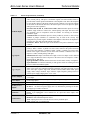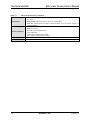
1
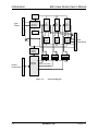
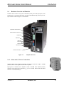
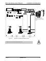
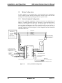
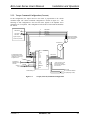
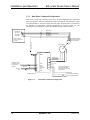
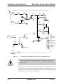
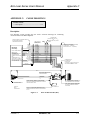
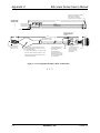
BAL LINEAR AMPLIFIER SERIES
USER’S MANUAL
P/N: EDA139 (V1.5)
AEROTECH, Inc. • 101 Zeta Drive • Pittsburgh, PA. 15238-2897 • USA
Phone (412) 963-7470 • Fax (412) 963-7459
Product Service: (412) 967-6440; (412) 967-6870 (Fax)
www.aerotech.com
If you should have any questions about the BA Linear Amplifier, comments regarding the documentation, or are
looking for manual updates, please refer to Aerotech online at:
http://www.aerotech.com.
For your convenience, a product registration form is available at our web site.
Our web site is continually updated with new product information, free downloadable software and special pricing on
selected products.
The BAL Linear Amplifier Series User’s Manual Revision History:
Rev 1.0
Rev 1.1
Rev 1.2
Rev 1.3
Rev 1.3a
Rev 1.4
Rev 1.5
© Aerotech, Inc., 2002
February 27, 1998
June 23, 1998
May 9, 2000
April 6, 2001
July 19, 2001
October 11, 2001
May 23, 2002
BA Linear Series User’s Manual
Table of Contents
TABLE OF CONTENTS
CHAPTER 1:
1.1.
1.2.
1.3.
1.4.
1.5.
CHAPTER 2:
2.1.
2.2.
2.3.
2.4.
2.5.
2.6.
2.7.
2.8.
CHAPTER 3:
3.1.
3.2.
3.3.
CHAPTER 4:
4.1.
INTRODUCTION ............................................................................ 1-1
Product Overview............................................................................... 1-1
Models, Options and Packages........................................................... 1-2
BAL Drive Package............................................................................ 1-3
Hardware Overview and Function ...................................................... 1-5
1.4.1. Motor and AC Power Connections....................................... 1-5
1.4.2. DIP Switch ........................................................................... 1-6
1.4.3. Potentiometers (POTs) ......................................................... 1-7
1.4.4. Connector J6 and Enable Indicator ...................................... 1-7
1.4.5. I/O Circuitry ....................................................................... 1-10
Safety Procedures and Warnings ...................................................... 1-12
INSTALLATION AND OPERATION ........................................... 2-1
Introduction ........................................................................................ 2-1
Jumper Selections............................................................................... 2-1
Wiring Configurations ........................................................................ 2-4
2.3.1. Velocity Command Configuration ....................................... 2-4
2.3.2. Torque Command Configuration (Current).......................... 2-5
2.3.3. Dual-Phase Command Configuration................................... 2-6
Three Phase Brushless Motors with Unconnected Phases.................. 2-7
Power and Control Connections ......................................................... 2-8
2.5.1. Setup – Torque Command Mode (Current).......................... 2-8
2.5.2. Setup – Velocity Command Mode ....................................... 2-9
2.5.3. Setup – Dual Phase Command Mode ................................. 2-11
DC Brush Motor Operation .............................................................. 2-12
2.6.1. Single Brush Motor ............................................................ 2-12
2.6.2. Multiple Brush Motor ........................................................ 2-13
Motor Phasing Process ..................................................................... 2-14
2.7.1. Determining Phase/Hall Sequence ..................................... 2-14
Current Regulator Adjustments ........................................................ 2-16
TECHNICAL DETAILS.................................................................. 3-1
Part Number and Ordering Information.............................................. 3-1
Electrical Specifications ..................................................................... 3-2
BAL Amplifier Dimensions................................................................ 3-5
TROUBLESHOOTING................................................................... 4-1
Amplifier Related Problems ............................................................... 4-1
APPENDIX A: GLOSSARY OF TERMS ............................................................... A-1
APPENDIX B: WARRANTY AND FIELD SERVICE...........................................B-1
APPENDIX C: CABLE DRAWINGS .......................................................................C-1
INDEX
REVISION HISTORY
Version 1.5
∇ ∇ ∇
Aerotech, Inc.
iii
Table of Contents
iv
BA Linear Series User’s Manual
Aerotech, Inc.
Version 1.5
BA Linear Series User’s Manual
List of Figures
LIST OF FIGURES
Figure 1-1.
Figure 1-2.
Figure 1-3.
Figure 1-4.
Figure 1-5.
Figure 1-6.
Figure 1-7.
BAL Series Amplifier......................................................................... 1-1
Functional Diagram ............................................................................ 1-4
Amplifier Hardware............................................................................ 1-5
Fault Output...................................................................................... 1-10
Enable/Shutdown Inputs................................................................... 1-10
6 Limit Inputs ................................................................................. 1-11
Hall and Encoder Inputs ................................................................... 1-11
Figure 2-1.
Figure 2-2.
Figure 2-3.
Figure 2-4.
Figure 2-5.
Figure 2-6.
Figure 2-7.
Figure 2-8.
Figure 2-9.
Figure 2-10.
BAL Board Assembly with Jumper Locations ................................... 2-3
Velocity Command Configuration...................................................... 2-4
Torque (Current) Command Configuration ........................................ 2-5
Dual-Phase Command Configuration ................................................. 2-6
Connection of Six Wire Motors to BAL Series Amplifiers ................ 2-7
Command Signal Adjustment Portion of the Pre-amplifier
Circuit............................................................................................... 2-10
Single Brush Motor Configuration with Tach .................................. 2-12
Multiple Brush Motor Configuration................................................ 2-13
Motor Phasing .................................................................................. 2-15
Current Command Interface Circuit ................................................. 2-16
Figure 3-1.
BA Linear Amplifier Dimensions....................................................... 3-5
Figure C-1.
Figure C-2.
BAL Feedback Cable (PFC)...............................................................C-1
BAL Light Duty Brushless Motor Cable (PMC) ................................C-2
∇ ∇ ∇
Version 1.5
Aerotech, Inc.
v
List of Figures
vi
BA Linear Series User’s Manual
Aerotech, Inc.
Version 1.5
BA Linear Series User’s Manual
List of Tables
LIST OF TABLES
Table 1-1.
Table 1-2.
Table 1-3.
Table 1-4.
BAL Models and Voltage Configurations ........................................ 1-2
DIP Switch Functions ....................................................................... 1-6
Potentiometer Functions ................................................................... 1-7
Connector J6 Pinouts.........................................................................1-8
Table 2-1.
Jumper Selections..............................................................................2-2
Table 3-1.
Table 3-2.
Table 3-3.
Part Number and Ordering Example (BAL20-40-A-AH)................. 3-1
Part Number and Ordering Options.................................................. 3-1
Electrical Specifications ....................................................................3-2
Table 4-1.
Amplifier Faults, Causes, and Solutions............................................4-1
Table R-1.
Revisions ..........................................................................................R-1
∇ ∇ ∇
Version 1.5
Aerotech, Inc.
vii
List of Tables
viii
BA Linear Series User’s Manual
Aerotech, Inc.
Version 1.5
BA Linear Series User’s Manual
Introduction
CHAPTER 1: INTRODUCTION
In This Section:
• Product Overview..................................................... 1-1
• Models, Options and Packages................................. 1-2
• BAL Drive Package.................................................. 1-3
• Hardware Overview and Function ............................ 1-5
• Safety Procedures and Warnings ............................ 1-12
1.1.
Product Overview
The BAL Series amplifiers are highly reliable brushless servo amplifiers (refer to Figure
1-1) that are easily adaptable to drive brush or brushless servomotors. The BAL amplifier
package is a complete modular unit that includes heat sink, metal cover, control and bus
power supplies that operate at ±40 VDC or ±80 VDC. The BAL drives provide the
designer with servo drive flexibility for use in applications such as:
½
½
½
½
½
CMM (Coordinate Measurement Machines)
x-y stages
inspection and scanning (w/o Air Bearings)
medical
and semiconductor fabrication.
Figure 1-1.
Version 1.5
BAL Series Amplifier
Aerotech, Inc.
1-1
Introduction
BA Linear Series User’s Manual
1.2.
Models, Options and Packages
A list of the available models and the voltage configurations is shown in Table 1-1.
Table 1-1.
BAL Models and Voltage Configurations
Model
Standard Voltage
Configuration
Peak Output
Current
Continuous Output
Current (peak)
BAL20-40-X
±40 VDC
20A
10A
BAL10-80-X
±80 VDC
10A
5A
BAL10-40-X
±40 VDC
10A
5A
Where:
X = A for 110 VAC single phase input power.
X = B for 220 VAC single phase input power.
X = C for 100 VAC sinlge phase input power.
The BAL drives feature self-commutation with analog or digital Hall effect feedback
signals. The BAL drives even include a 5 VDC, 250 mA supply to power encoders and
Hall effect devices (HEDs). Each model is jumper selectable, providing the capability to
drive both brush and brushless motors. Complete electrical isolation is provided between
the control stage and the power stage for all models of the BAL Series. This is
accomplished with a transformer isolated control voltage power supply and opto-isolation
of the drive signals, current command signals and fault signal between the control and
power stages. Each drive is fully protected against the following fault conditions:
➤ control power supply under voltage
➤ RMS current limit exceeded
➤ power stage bias supplies under voltage
➤ over temperature
➤ over current
➤ and excessive power transistor dissipation.
Operating modes include current command, velocity command or dual-phase command
(for brushless modes of operation only). For brush modes of operation, the available
operating modes are current command and velocity command. Differential inputs are used
for better noise immunity. Velocity feedback is from either an encoder or tachometer and
logic inputs include directional current limits and shutdown. Fault, current, and velocity
outputs simplify monitoring drive status. In addition, there is an option to drive three
brush motors in torque mode.
1-2
Aerotech, Inc.
Version 1.5
BA Linear Series User’s Manual
1.3.
Introduction
BAL Drive Package
A block diagram of the BAL Series servo amplifier is shown in Figure 1-2. This is a
simplified diagram of the internal modules of the BAL Series amplifier. Contained in the
drive is a 115/230 VAC 50/60 Hz step down toroidal isolation transformer that rectifies
its output to produce a ±40 VDC or a ±80 VDC bus depending on the model.
These buses power three class AB power amplifiers, each containing their own control
power supply and isolated current command input connections. These power amplifiers
work independently of each other, each only receiving a signal current command from the
control section, refer to Figure 1-2. In other words, each power amplifier has a current
regulating circuit and voltage regulating circuit, along with an adjustable current limit
time-out circuit and a dynamic power limit circuit.
The dynamic power limit circuit monitors the instantaneous power across each output
power transistor and clamps the incoming current command signal to a level just below
the second breakdown specification of the output transistor.
The current limit time-out circuit monitors the phase current. It sends a signal to the
control section to shutdown the entire servo amplifier, if the current in a given phase
exceeds a certain level (programmable) after a given time period. This time period is a
variable and depends on the amount of current above the programmed current threshold
level.
The control section contains its own isolated +5, ±12 VDC control supply. Depending on
the operating mode, the control section is responsible for accepting incoming current or
velocity command signals and providing digital or analog commutation processing on
these signals. In addition, it generates an internal velocity feedback signal from the
encoder, if the velocity mode is specified. Independent of the mode specified, the control
section produces three current command signals that are fed through opto-isolation to
each of the three amplifiers.
Version 1.5
Aerotech, Inc.
1-3
Introduction
BA Linear Series User’s Manual
+DC Bus
J8
HI
Input
Power
LO
Toroidal
115VAC/230VAC
Step Down
Transformer
“A”
Phase
Drive
“B”
Phase
Drive
“C”
Phase
Drive
G
-DC Bus
J8
A
Drive
Power
Supply
Drive
Power
Supply
Drive
Power
Supply
B
C
Motor
Connections
RT
G
+5V and
+/- 12V
POWER
SUPPLY
ISOLATION
Control
Connections
CONTROL
SECTION
J6
ISOLATION
ISOLATION
FAULT
CURRENT COMMAND “A”
CURRENT COMMAND “B”
CURRENT COMMAND “C”
Figure 1-2.
1-4
Functional Diagram
Aerotech, Inc.
Version 1.5
BA Linear Series User’s Manual
1.4.
Introduction
Hardware Overview and Function
The BAL Series consist of two power connections (motor power and input power), four
potentiometers, a 6-position DIP switch, an enable LED indicator lamp, and a 25-pin “D”
style connector. Refer to Figure 1-3 for locations.
Input Power Connection J8
Motor Power Connection J8
Enable LED
DIP Switch
Input POT
Tach POT
Gain POT
BALance Pot
Control Connection J6
Figure 1-3.
Amplifier Hardware
1.4.1. Motor and AC Power Connections
The three phase motor terminal connections are made at connections A, B, C, and RT
(Return). This area is designated as such on the amplifier.
Input power to the BAL series amplifier is made at the HI (line) and LO (neutral)
(or “G” Ground). Motor frame and shield
terminals with earth ground connected to
connect to a second Ground (G).
Version 1.5
Aerotech, Inc.
1-5
Introduction
CLOSED
OPEN
BA Linear Series User’s Manual
1.4.2. DIP Switch
There is a 6-position DIP switch on the BAL drive that provides three discrete functions.
The switch permits the user to control maximum allowable current to the motor (self
commutating modes only), velocity or current operational mode, and test mode. Figure 13 shows the location of this switch on the BAL drive. Refer to Table 1-2 for the exact
switch functions.
Table 1-2.
DIP Switch Functions
Switches
Position
Current Limit Peak
1
closed
Peak is 6% of Ipeak
(self commutating
modes only)
2
closed
Peak is 13% of Ipeak
3
closed
Peak is 27% of Ipeak
4
closed
Peak is 54% of Ipeak
closed
Closing this position allows the
BALance potentiometer to manually
control motor velocity or torque without
the need of an input signal depending
upon the setting of switch 10.
Test
5
Mode
6
Function
Velocity/Current mode - closing this
position enables the current mode.
The following examples should be used as a guideline for setting the DIP switches.
Example for a BAL20 - Setting Continuous Current Limits
To set the continuous current limit to 5.5A:
5.5A Continuous RMS x 1.414 = 7.8A continuous peak
(7.8A continuous peak/20A max peak) x 100 = 39%.
Open switches 1 and 4; close switches 2 and 3.
1-6
Aerotech, Inc.
Version 1.5
BA Linear Series User’s Manual
Introduction
1.4.3. Potentiometers (POTs)
Potentiometers INPUT, TACH, GAIN, and BALance are associated with the
pre-amplifier circuit contained in the amplifier. Refer to Figure 1-3 for location of the
pots on the BAL drive. These potentiometers are used to adjust the pre-amplifier gain
when the MODE switch is set for velocity control using an external DC tachometer or
incremental encoder for velocity feedback. Refer to Table 1-3 for pot functions.
Table 1-3.
Potentiometer
Potentiometer Functions
CW
CCW
Function
GAIN
decrease
increase
This pot adjusts the AC gain of the preamplifier.
INPUT
increase
decrease
This pot adjusts the DC gain of the input
command present at J6 Pins 8 & 21.
TACH
increase
decrease
This pot adjusts the DC gain of the tach or
encoder derived velocity feedback input
present at J6-Pin 3.
BALance
Provides the means of canceling small DC
offsets that may be present in the
pre-amplifier circuit.
1.4.4. Connector J6 and Enable Indicator
Connector J6 (25-pin “D” type, female) provides the interface for input and output
control connections. Refer to Table 1-4 for connector J6 pinouts. The LED ENABLE
indicator will illuminate at all times until there is a fault or external shutdown, then the
indicator will be off and motor power will be removed. Refer to Figure 1-3 for location
of these items.
Version 1.5
Aerotech, Inc.
1-7
Introduction
Table 1-4.
Pin #
BA Linear Series User’s Manual
Connector J6 Pinouts
Input or
Output
Signal
Pin 1
shield
ground
Pin 2
output
power
Pin 3
input /
output
+tach
Pin 4
input (1)
Hall A
Pin 5
input
cosine
Pin 6
Pin 7
input
input
cosine-N
ground
Pin 8
input
+input
Pin 9
input
icmda
Pin 10
input (1)
shutdown
Pin 11
input (1)
+ilmt
Pin 12
input
icmdc
Pin 13
N.C.
Pin 14
signal
common
ground
Pin 15
input
-tach
Pin 16
input (1)
Hall B
1-8
Function
Connection point to earth ground. Used for reducing electrical noise in
control and feedback signals. Typically connected to the foil shield of a
shielded cable.
On board 5V power supply. Pin 2 is intended for powering an encoder and
can supply up to 250mA of current.
Tachometer input for velocity feedback, (encoder vs. tach velocity
feedback is jumper selectable). A tachometer may be used in the velocity
loop configuration to provide negative feedback to the amplifier. This
allows the amplifier to close the servo loop and control the stability of the
loop. If an encoder is used for velocity feedback, this pin serves as an
output for monitoring velocity. (approx. 1V/KRPM)
Hall effect A. One of three commutation signals used with brushless
motors. Used in conjunction with Hall effect B and Hall effect C to
provide motor rotor position information to the amplifier. This input is
also for connection of analog Hall A, if applicable.
Cosine signal from encoder. Optionally used, in conjunction with sine for
deriving an electronic tachometer signal. Line receiver input
Compliment of cosine (J6 - 5). Line receiver input.
Signal common. Electrical reference for all control circuitry on amplifier.
Non-inverting input of differential input circuit. A positive voltage on this
input causes CCW motor rotation (torque or velocity mode). For single
ended operation, connect command to this input and ground (Pin 21 of J6).
Current command A. Jumper selectable current command input. Bypasses
differential input, pre-amplifier, and self commutation circuit.
Jumper selectable active high or active low input. Used to shut off power
stage and therefore remove all power to the motor.
Directional current limit input. When pulled to its active state, motion in
the positive direction (CW motor shaft rotation) is inhibited (jumper
selectable).
Current command C. Allows control of phase C current when jumper JP8
is set to 2-3. Normally phase C current is derived internally from phase A
and B currents.
Not used.
Electrical reference for all control circuitry on amplifier. This pin is
intended to be used as the connection point for the signal common of an
encoder. (Used in conjunction with Pin 2 as the power supply connections
to an encoder.)
Recommended reference input for tachometer. This point is identical to
signal common.
Hall effect B. One of three commutation signals used with brushless
motors. Used in conjunction with Hall effect A and Hall effect C. This
input is also for connection of analog Hall B, if applicable.
Aerotech, Inc.
Version 1.5
BA Linear Series User’s Manual
Table 1-4.
Pin #
Introduction
Connector J6 Pinouts (Continued)
Input or
Output
Signal
Function
Pin 17
input (1)
Hall C
Hall effect C. One of three commutation signals used with brushless
motors. Used in conjunction with Hall effect A and Hall effect B.
Pin 18
input
sine
Sine signal from encoder. Optionally used, in conjunction with cosine for
deriving an electronic tachometer signal. Line receiver input.
Pin 19
input
sine-N
Compliment of sine (J6- 18). Line receiver input.
Pin 20
input
power
On board 5V power supply. Same as J6 pin 2.
Pin 21
input
-input
Inverting input of differential input circuit. A positive voltage on this input
causes CW motor rotation (torque or velocity mode). For single ended
command operation, ground this connection and connect signal to Pin 8 of
J6.
Pin 22
input
icmdb
Current command B. Jumper selectable current command input. Bypasses
differential input, pre-amplifier, and self-commutation.
Pin 23
output
-fault
Jumper selectable active high or active low (open collector) output. Used
to indicate the status of the power stage (amplifier enabled or faulted).
-ilmt
Directional current limit input. When pulled to its active state, motion in
the negative direction (CCW motor shaft rotation) is inhibited (jumper
selectable).
-icmd
Current command monitor. Representative of the current command (self
commutating modes only).
Pin 24
Pin 25
input (1)
output
1. Denotes input pull up to internal +5 V through a 10K resistor.
Version 1.5
Aerotech, Inc.
1-9
Introduction
BA Linear Series User’s Manual
1.4.5. I/O Circuitry
The following shows the internal circuitry for the BAL amplifier. Note that all of the
logic inputs can tolerate +24VDC.
P6-23
C
FAULT OUTPUT
B
Q3
MMBT2222
2K
E
Figure 1-4.
*capable of 160mA max.
Fault Output
+5V
10K
SHUTDOWN / ENABLE
P6-10
10K
.1UF
Figure 1-5.
1-10
74HC14
Enable/Shutdown Inputs
Aerotech, Inc.
Version 1.5
BA Linear Series User’s Manual
Introduction
+5V
10K 1%
P6-11
+ILMT
10K 1%
+5V
.1UF
74HC14
10K 1%
P6-24
-ILMT
10K 1%
.1UF
6 Limit Inputs
Figure 1-6.
+5V
+5V
R224
10K 1%
P6-4
74HC14
+5V
R225
10K 1%
R226
10K 1%
R229
HEA
1
2
10K 1%
74HC14
P6-16
R228
HEB
3
4
10K 1%
74HC14
P6-17
R227
HEC
5
6
10K 1%
C186
100PF
P6-18
P6-19
P6-5
P6-6
C187
100PF
C188
100PF
74HC14
SIN
6
SIN-N
R219
C179
180
.01UF
R220
C181
5
3
SN75157
COS
1
COS-N
180
Figure 1-7.
Version 1.5
.01UF
7
2
SN75157
Hall and Encoder Inputs
Aerotech, Inc.
1-11
Introduction
BA Linear Series User’s Manual
1.5.
Safety Procedures and Warnings
The following statements apply wherever the Warning or Danger symbol appears within
this manual. Failure to observe these precautions could result in serious injury to those
performing the procedures and/or damage to the equipment.
To minimize the possibility of electrical shock and bodily injury, ensure that the
motor is decoupled from the mechanical system and no harm to personnel will result
if the motor begins to spin.
WARNING
Before performing the following steps, ensure that the motor is completely
disconnected from the amplifier and the associated mechanical system.
WARNING
To minimize the possibility of electrical shock and bodily injury when any electrical
circuit is in use, ensure that no person comes in contact with the circuitry.
To minimize the possibility of bodily injury, make certain that all electrical power
switches (all switches external to the amplifier) are in the off position prior to making
any mechanical adjustments.
∇ ∇ ∇
1-12
Aerotech, Inc.
Version 1.5
BA Linear Series User’s Manual
Installation and Operation
CHAPTER 2: INSTALLATION AND OPERATION
In This Section:
• Introduction ................................................................................ 2-1
• Jumper Selections........................................................................ 2-1
• Wiring Configurations................................................................. 2-4
• Three Phase Brushless Motors with Unconnected Phases........... 2-7
• Power and Control Connections .................................................. 2-8
• Motor Phasing Process .............................................................. 2-14
• Current Regulator Adjustments ................................................ 2-16
2.1.
Introduction
This section covers the hardware configurations using the switches, jumpers, connectors,
and power hook-ups when used with a brush or brushless DC motor. Wiring, grounding,
and shielding techniques, an explanation of the current regulator adjustment, and the
motor phasing process are also covered in this section.
2.2.
Jumper Selections
The BAL Series amplifiers are jumper selectable providing the user with quick
reconfiguration capability of operating modes. Table 2-1 lists the jumpers and the default
configurations for the amplifiers. Figure 2-1 highlights where the jumpers are located on
the board (with the default configurations).
Aerotech brushless motors should be set for 0 degree Hall commutation shift. Motors
from other manufacturers may require a 30-degree Hall commutation shift. Consult
the motor manufacturer for details.
Version 1.5
Aerotech, Inc.
2-1
Installation and Operation
Table 2-1.
BA Linear Series User’s Manual
Jumper Selections
Jumpers Positions JP1
JP2
JP3
JP4
JP5
JP6
JP7
1-2
2-3
1-2
2-3
1-2
2-3
1-2
2-3
1-2
2-3
1-2
2-3
1-2
2-3
1-2
JP8
2-3
1-2
JP9
3-4
5-6
7-8
1-2
JP10
JP11
JP12
2-3
1-2
2-3
1-2
2-3
1-2
JP13
3-4
5-6
JP14/JP15
JP18
JP19
7-8
1-2
2-3
1-2
3-4
1-2
3-4
Function
Active low +ILMT. Logic on J6-11 stops CW (+) motor movement (default).
Active high +ILMT. Logic on J6-11 stops CW (+) motor movement.
Active low -ILMT. logic on J6-24 stops CCW (-) motor movement (default).
Active high -ILMT. logic on J6-24 stops CCW (-) motor movement.
Selects AC Brushless operation mode (default).
Selects DC Brush operation mode.
Selects 0 degrees Hall commutation shift for AC Brushless operation(default).
Selects 30 degrees Hall commutation shift for AC Brushless operation.
Active high fault output. Open collector output on J6-23 goes to high impedance state for drive fault condition
(default).
Active low fault output. Open collector output on J6-23 is driven to signal common for drive fault condition.
Active high shutdown input. Logic high on J6-10 shuts off power stage (default).
Active low shutdown input. Logic low on J6-10 shuts of power stage.
Internal digital Tach feedback enabled (velocity mode).
External Tach feedback through J6-3 (velocity mode) or internal digital Tach feedback disabled (current mode)
(default).
Phase “C” current command for AC Brushless operation derived internally.(default).
Current command for DC Brush operation on phase “C” output (J6-12).
Also doubles as phase “C” input for brushless motor operation (J6-12).
Phase “A”, Phase “B” current command for AC Brushless operation derived internally from digital Hall or analog
feedback (default).
Phase “A”, current command for AC Brushless operation derived externally through pins 9 and 22 of J6 respectively.
Phase “A”, current command for AC Brushless operation derived internally from analog Hall feedback (factory
option).
Phase “A”, current derived externally through differential inputs (factory option).
Phase “A”, current commands produced by digital Hall feedback aligned for 30 degree Hall commuation shift.
Phase “A”, current commands produced by digital Hall feedback aligned for 0 degree Hall commutation shift.
(default).
Internal velocity circuit disabled. (default)
Internal velocity circuit enabled.
Phase “B” current commands produced by digital Hall feedback aligned for 30 degree Hall commuation shift.
Phase “B” current commands produced by digital Hall feedback aligned for 0 degree Hall commutation shift.
(default).
Phase “B” current command for AC Brushless operation derived internally from digital Hall or analog feedback
(default).
Phase “B” current command for AC Brushless operation derived externally through pins 9 and 22 of J6 respectively.
Phase “B” current command for AC Brushless operation derived internally from analog Hall feedback (factory
option).
Phase “B”, current derived externally through differential inputs (factory option).
Signal common of control section connected to earth ground (J8 , “G” connections) (default).
Signal common not referenced to earth ground.
Digital Hall commutation, Phase A Hall.
Analog Hall commutation, Phase A Hall. (* Factory Option)
Digital Hall commutation, Phase B Hall.
Analog Hall commutation, Phase B Hall. (* Factory Option)
JP17, JP27, and JP37 are for factory use only.
2-2
Aerotech, Inc.
Version 1.5
INPUT
TACH
GAIN
BALANCE
BA Linear Series User’s Manual
Installation and Operation
SW4
J6
1
J8
1
R1 R2 R3 R4
5
J9 1
1
J10
1
TP9
1
JP19
2
4
6
8
JP13
RCN1
1
7
JP12
R7
JP15
TP5
JP18
JP14
1
F1
F2
R8
JP11
1
JP2
JP4
1
1
JP6
1
1
1
1
JP1
JP3
JP7
JP8
1
R5
JP10
1
R6
1
1
JP5
TP4
TP1
7
2
4
6
8
JP9
Remove cover to gain
access to jumpers and test
points.
R33
R23
TP35
TP36
R13
TP25
TP26
SW3
TP15
TP16
SW2
SW1
TP30
TP34
TP20
TP24
1
1
JP37
JP27
TP10
TP14
1
JP17
R20 R21 R22
R30 R31 R32
R10 R11 R12
1
1
J2
Figure 2-1.
1
J5
1
J4
J3
BAL Board Assembly with Jumper Locations
Remove AC power from unit before removing cover.
DANGER
Version 1.5
Aerotech, Inc.
2-3
Installation and Operation
2.3.
BA Linear Series User’s Manual
Wiring Configurations
The BAL amplifiers can be integrated into a system using three basic configurations;
velocity command, current command, and dual phase command. Each of these has their
advantages and disadvantages depending upon the user’s specific needs.
2.3.1. Velocity Command Configuration
In the velocity command configuration, the speed of the motor is controlled by the
amplifier. A feedback signal from either a DC tachometer or an incremental encoder is
monitored by the amplifier. From this signal, the amplifier adjusts the velocity of the
motor accordingly depending upon the velocity command from the external controller. In
this configuration, the amplifier closes and controls the velocity loop. The velocity
command configuration is shown in Figure 2-2. This configuration can drive both brush
and brushless DC motors.
MKR, MKR-N
COS, COS-N
SIN, SIN-N
2
MKR, MKR-N
3
2
2
2
Hall A, B, C
COS, COS-N
SIN, SIN-N
5V, SIG COM
Signals to Optional
Square Wave Quadrature
Encoder with Commutation
Tracks or Hall Sensors
Position Loop Controller
5V, SIG COM
SIN/SIN-N
COS/COS-N
HALL A, B, C
Brushless Motor
J6
2, 20
7
18, 19
5, 6
For Single Ended Command
Input, Connect Signal To J6-8
(+Input) And To J6-21 (-Input)
To Signal Common.
Single-Ended or
Differential
Velocity Command
4
16
17
SIG COM
Shutdown
Fault
5V
SIG COM
SIN
COS
HALL A
HALL B
HALL C
8
21
+ INPUT
- INPUT
14
SIG COM
10
23
SHUTDOWN
FAULT
1
SHIELD
BAL AMPLIFIER
A
B
C
Motor Phase A
Motor Phase B
Motor Phase C
RT
LO
HI
* The RT connection is used
with six wire, three phase
motors and with single-phase
brush AC motors.
Earth Ground
Shielded Cabling
AC LO 115/230 VAC 50/60 HZ
AC HI (Depending on Mode)
Figure 2-2.
2-4
Velocity Command Configuration
Aerotech, Inc.
Version 1.5
BA Linear Series User’s Manual
Installation and Operation
2.3.2. Torque Command Configuration (Current)
In this configuration, the output current to the motor is proportional to the current
command input. The current command configuration is shown in Figure 2-3. The
advantage to this configuration is the sine and cosine signals to the amplifier and a
tachometer are not required. This configuration will also drive both brush and brushless
DC motors.
MKR, MKR-N
COS, COS-N
SIN, SIN-N
2
MKR, MKR-N
3
2
2
2
Hall A, B, C
COS, COS-N
SIN, SIN-N
5V, SIG COM
Signals to Optional
Square Wave Quadrature
Encoder with Commutation
Tracks or Hall Sensors
Position Loop Controller
5V, SIG COM
SIN/SIN-N
COS/COS-N
HALL A, B, C
Brushless Motor
J6
2, 20
7
18, 19
5, 6
For Single Ended Command
Input, Connect Signal To J6-8
(+Input) And To J6-21 (-Input)
To Signal Common.
Single-Ended or
Differential Current
Command
4
16
17
SIG COM
Shutdown
Fault
5V
SIG COM
SIN
COS
HALL A
HALL B
HALL C
8
21
+ INPUT
- INPUT
14
SIG COM
10
23
SHUTDOWN
FAULT
1
SHIELD
BAL AMPLIFIER
A
B
C
Motor Phase A
Motor Phase B
Motor Phase C
RT
LO
HI
* The RT connection is used
with six wire, three phase
motors and with single-phase
brush AC motors.
Earth Ground
Shielded Cabling
AC LO 115/230 VAC 50/60 HZ
AC HI (Depending on Mode)
Figure 2-3.
Version 1.5
Torque (Current) Command Configuration
Aerotech, Inc.
2-5
Installation and Operation
BA Linear Series User’s Manual
2.3.3. Dual-Phase Command Configuration
This mode is used with a brushless motor only. In this configuration, the differential
input, pre-amplifier, and self-commutation circuits are bypassed. The dual-phase inputs
are sinusoidal and are 120° out of phase from each other. The third phase is generated by
the amplifier. The dual-phase command configuration is shown in Figure 2-4. The
advantage to this configuration is that it provides the smoothest possible motion.
MKR, MKR-N
HALL A, B, C
COS, COS-N
SIN, SIN-N
2
MKR, MKR-N
3
2
2
2
Hall A, B, C
COS, COS-N
SIN, SIN-N
5V, SIG COM
Signals to Optional
Position Velocity Loop
Controller
Square Wave Quadrature
Encoder with Commutation
Tracks or Hall Sensors
5V, SIG COM
Brushless Motor
J6
2, 20
7
BAL AMPLIFIER
5V
SIG COM
A
B
C
Dual Phase Current
Command Provided
By Commutating
Controller
SIG COM
Shutdown
Fault
9
22
ICMDA
ICMDB
14
SIG COM
10
23
SHUTDOWN
FAULT
1
SHIELD
RT
LO
HI
Motor Phase A
Motor Phase B
Motor Phase C
*
* The RT connection is used
with six wire, three phase
motors and with single-phase
brush AC motors.
Earth Ground
Shielded Cabling
AC LO 115/230 VAC 50/60 HZ
AC HI (Depending on Mode)
Figure 2-4.
2-6
Dual-Phase Command Configuration
Aerotech, Inc.
Version 1.5
BA Linear Series User’s Manual
2.4.
Installation and Operation
Three Phase Brushless Motors with Unconnected Phases
Most three phase brushless motors require only three connections between the servo
amplifier and the motor. This is due to the motor phases internally connected in a Wye or
Delta style. This form of connection simplifies wiring, ensuring that the servo amplifier
only controls and monitors two phase currents, since the third phase current is always the
sum of the first two phase currents.
However, this simplicity has one drawback. This drawback is phase winding imbalances
that can cause torque ripple and make it difficult to compensate, since the servo amplifier
only controls two of the three phase currents. The BAL Series amplifier over comes this
problem by providing the “RT” (return) connection for six wire motors, like the Aerotech
BLM Series linear motors.
Since the BAL Series amplifier independently controls current in each of its three phases,
six wire motors can be connected as shown in Figure 2-5. In this configuration, offset
and/or gain adjustments of current made in one phase do not affect those set in the other
two phases.
J8
A
B
C
G
RT
Rotary or
Linear Motor
HI
LO
G
Figure 2-5.
Version 1.5
Connection of Six Wire Motors to BAL Series Amplifiers
Aerotech, Inc.
2-7
Installation and Operation
2.5.
BA Linear Series User’s Manual
Power and Control Connections
The BAL drives can be wired into a system in one of two ways depending upon the
desired mode of operation. Command signals can be referenced to velocity or torque
(current) control signals. The user has access to four potentiometers, three that adjust gain
while the fourth (BALance) compensates for input signal offsets. Figure 2-6 illustrates a
portion of the pre-amplifier circuit that is accessible to the user for adjusting command
signal gains.
For adjustments in gain roll-off, “Personality Module” RCN1, pins 1-16, 2-15, 3-14,
5-12, and 7-10 are provided for the selection of the appropriate resistor/capacitor pair
factory default values are shown in Figure 2-6.
2.5.1. Setup – Torque Command Mode (Current)
To setup the pre-amplifier circuit for use in the torque (current command) mode,
configure the BA amplifier as follows:
• Place SW4 position 6 (mode) to closed (default)
• Place SW4 position 5 (test) to open (default)
• SW4 positions 1 through 4 selects current limit
• Potentiometers “INPUT” set full CW and “GAIN” set full CCW to provide
a transconductance gain of ± 10 volts for full current output.
“BALance”and “TACH” have no effect.
• JP7 set to 2-3 (default)
• JP9 and JP13 set to 1-2 (default)
• JP3 set to 1-2 (default) for brushless motor operation or 2-3 for brush motor
operation
• JP10, JP12, set to 2-3 and JP4 set to 1-2 for zero (0) degrees commutation
(default) or JP10, JP12 set to 1-2 and JP4 set to 2-3 for thirty (30) degrees
commutation (brushless motor operation only).
• Set JP8 to 1-2 (default)
With this configuration, an input signal of ± 10 volts to pins +INPUT and -INPUT will
produce the maximum current output signal (viewed at J6 pin 25 ICMD) of ± 6 volts.
Switch “SW4” 1 through 4 are used to scale this ±6 volt signal from zero to maximum
current. Refer to Figure 2-3 for torque command configuration.
2-8
Aerotech, Inc.
Version 1.5
BA Linear Series User’s Manual
Installation and Operation
2.5.2. Setup – Velocity Command Mode
For this mode, a velocity feedback signal is required. This feedback signal can be derived
from two sources. From an analog DC tachometer that is connected to the +TACH pin or
from an incremental encoder that is connected to the sine and cosine pins (refer to Figure
2-2). To setup the pre-amplifier circuit for use in the velocity command mode, configure
the BAL amplifier as follows:
• Place SW4 position 6 (mode) to open
• Place SW4 position 5 (test) to open (default)
• SW4 positions 1 through 4 selects current limit
• Potentiometers “INPUT”, “GAIN”, “BALance”, and “TACH” adjust
pre-amplifier gain and offset.
For most applications under the velocity command mode, the preferred starting point for
setting the three gain pots is as follows:
INPUT pot - 1/3 CW from full CCW
TACH pot - full CW
GAIN pot - full CW
These initial settings will usually generate a stable system if it is assumed that the
tach feedback gain is around 6 volts/Krpm, or if an encoder is used and the line
resolution is between 1,000 and 1,500 per revolution.
•
•
•
•
•
JP7 set to 1-2 for encoder or 2-3 (default) for tachometer velocity feedback
JP9 and JP13 set to 1-2 (default)
JP3 set to 1-2 (default) for brushless motor operation or 2-3 for brush motor
operation
JP10, JP12 set to 2-3 and JP4 set to 1-2 for zero (0) degrees commutation
(default) or JP10, JP12 set to 1-2 and JP4 set to 2-3 for thirty (30) degrees
commutation (brushless motor operation only).
Set JP8 to 1-2 (default)
Version 1.5
Aerotech, Inc.
2-9
Installation and Operation
NOTE :
BA Linear Series User’s Manual
For single ended command input, connect signal to P1-8 (+input) and the P1-21 (-Input) to signal common.
-INPUT
P6 - 21
20.0 K
6.2 K
10.0 K
CW
LM348
+INPUT
P6 - 8
20.0 K
6.2 K
TEST
1M
10.0 K
+2.5
CW
6.2 K
.1
10.0 K
BALANCE
-2.5
56K
7
RCN1
10 8 9
RCN1
GAIN
10.0 K
CW
MODE
10.0 K
2K
+TACH
20.0 K
CW
P6 - 3
10M
10.0 K
510 OHM
10.0 K
LM348
(+/- 6.0 Volts
equals max.
current)
.004uF
3
2
Current
Command to
Commutation
Logic
1
JP14
Encoder Derived
Velocity
(Assumes SW2
Positions 1
through 4 are
closed)
ICMD
1K
P6-25
Figure 2-6.
Command Signal Adjustment Portion of the Pre-amplifier Circuit
To minimize the possibility of electrical shock and bodily injury, ensure that the
motor is decoupled from the mechanical system to avoid personal injury if the motor
begins to spin.
WARNING
Starting with a zero input command signal, apply power to the amplifier. If the motor
spins uncontrollably, remove power and switch the polarity of the tach input signal. If an
encoder is being used, switch the sine and cosine input signals. Verify compliment signals
(sin & sin-N, cos & cos-N) are of correct phasing.
2-10
Aerotech, Inc.
Version 1.5
BA Linear Series User’s Manual
Installation and Operation
Again, apply power to the amplifier. If the motor begins to oscillate, turn the TACH pot
CCW until the oscillation stops. The GAIN and TACH potentiometers can be adjusted to
provide maximum stiffness on the motor shaft.
If the desired stiffness is unattainable, the components connected to personality
module RCN1 pins 5-12 and 7-10 may be need to be changed.
The BALance pot is used to cancel any bias in the internal or external control circuit that
would cause the motor to rotate when the input command signal is zero.
If the TEST switch is closed the effects of the BALance pot are greatly magnified. This is
useful when a test bias signal is desired (for velocity or torque modes) to be applied to the
amplifier without introducing an external command signal.
2.5.3. Setup – Dual Phase Command Mode
To setup the pre-amplifier circuit for use in the dual phase mode, configure the BA
amplifier as follows:
• JP9 and JP13 are set to 3-4
• JP8 is set to 1-2 (default).
This mode is used with brushless motors only. Refer to Figure 2-4 for dual phase
command configuration.
Version 1.5
Aerotech, Inc.
2-11
Installation and Operation
2.6.
BA Linear Series User’s Manual
DC Brush Motor Operation
The BAL can control up to three brush motors. There are two different configurations for
brush mode operation.
2.6.1. Single Brush Motor
In this mode, a brush motor can be controlled in either velocity mode or current mode,
refer to Figure 2-7. The connection of the motor phase to the amplifier is done through
phase A and phase C. This configuration allows the motor to see the entire bus. Meaning,
if a BAL10-40 is the amplifier, then the brush motor will have 80 volts across its
terminals and a BAL10-80 will put 160 volts across the motor terminals (Differential at
full speed). Connecting the "+" side of the motor to A and "-" to the RT (Return) allows
the motor to operate in a single-ended mode. This means that the A terminal will swing
plus and minus with respect to RT. For a BA10-40, the motor will only see +40V or -40V
maximum; not 80V. This permits lower voltage DC motors to be used safely with BAL.
The jumper settings for velocity or torque mode can be found in Section 2.5.1. and
Section 2.5.2.
+
T
-
DC Motor
J6
2, 20
5V
BAL AMPLIFIER
MA
+
3
7
-
SIG COM
Motor Phase A
A
B
C
Motor Phase C
OR
Differential
Velocity Or
Torque CMD
SIG COM
Shutdown
Fault
RT
LO
8
21
+ INPUT
14
SIG COM
For Single Power Supply
10
23
SHUTDOWN
FAULT
Operation
1
- INPUT
HI
SHIELD
Earth Ground
Shielded Cabling
AC LO 115/230 VAC 50/60 HZ
AC HI (Depending on Mode)
Figure 2-7.
2-12
Single Brush Motor Configuration with Tach
Aerotech, Inc.
Version 1.5
BA Linear Series User’s Manual
Installation and Operation
2.6.2. Multiple Brush Motor
The BAL can control up to three brush motors in torque mode, refer to Figure 2-8. In this
mode, "motor +" of each motor connects to the appropriate phase on the amplifier and the
"motor -" connects to the return (RT). While operating in this mode, each motor can only
see half of the bus. Meaning, BAL10-40 drops 40 volts across the motor and a BAL10-80
drops 80 volts across the motor. The jumper configurations for this mode are:
•
•
•
JP9 and JP13 set to 3-4
JP8 set to 2-3.
JP3 set to 2-3.
DC Motor
J6
2, 20
5V
7
SIG COM
A
B
C
Motor C Torque CMD
Motor A Torque CMD
Motor B Torque CMD
14
ICMDC
ICMDA
ICMDB
SIG COM
10
23
SHUTDOWN
FAULT
1
SHIELD
12
9
22
SIG COM
Shutdown
Fault
+
BAL AMPLIFIER
Motor Phase A
Motor Phase B
Motor Phase C
RT
LO
HI
MA
+
MB
MC
+
-
Earth Ground
Shielded Cabling
AC LO 115/230 VAC 50/60 HZ
AC HI (Depending on Mode)
Figure 2-8.
Version 1.5
Multiple Brush Motor Configuration
Aerotech, Inc.
2-13
Installation and Operation
2.7.
BA Linear Series User’s Manual
Motor Phasing Process
When configuring the BAL amplifier to run a brushless motor, the commutation signal
input connections (labeled HALL A, B, C on connector J6 in velocity or torque command
mode pins 4, 16, and 17) are necessary. Two sequences of 30° or 0° (default) signal shift
can be used, depending on the setting of jumpers JP4, JP10, and JP12. These sequences
and the generated output motor phase voltages (motor output connections A, B, and C
with respect to a real or pseudo neutral connection) are shown in Figure 2-9 The voltages
generated are made under the conditions of a positive signal placed at +INPUT with
respect to -INPUT at control signal input/output connector J6. A “0” for the given HALL
input indicates zero voltage or logic low, where a “1” indicates five volts or logic high.
If an Aerotech brushless motor is used with the BAL amplifier, motor phase and
HALL connections can be easily determined by referring to the system
interconnection drawings in Figure 2-2, Figure 2-3, and Figure 2-4.
2.7.1. Determining Phase/Hall Sequence
For a motor with an unknown phase/hall sequence, a simple test can be performed on the
motor to determine the proper connections to the BAL amplifier.
Before performing the following steps, ensure that the motor power leads are
completely disconnected from the amplifier.
The tests outlined below do not require that the amplifier be turned on since
Figure 2-7 illustrates the generated output voltage of the amplifier relative to the
input Hall sequences.
The equipment needed for this test is a two-channel oscilloscope and three resistors
(typically 10 Kohm, 1/2 watt) wired in a “Wye” configuration.
Connect the ends of the three resistors to motor terminals A, B, C. Use one channel of the
oscilloscope to monitor motor terminal A with respect to the “Wye” neutral (i.e., the
point where all three resistors are connected together). Turn the shaft of the motor CCW
and note the generated voltage. This voltage represents the “phase A to neutral” CEMF.
With the second oscilloscope probe, determine the Hall switch that is “in phase” with this
voltage. Similarly, phase B and C should be aligned with the other two Hall switches.
2-14
Aerotech, Inc.
Version 1.5
BA Linear Series User’s Manual
Installation and Operation
Refer to Figure 2-9 and note the generated output voltages of the amplifier relative to the
Hall sequences applied to HALL A, HALL B, and HALL C connections at connector
J6. For proper operation, the CEMF generated motor phase voltages should be aligned to
the amplifier’s output generated voltage with the given Hall effect sequence shown in.
If the sequence of Hall signals relative to the generated motor voltage (e.g. motor CEMF)
is adhered to as illustrated in Figure 2-9; a positive (+) voltage signal applied to pin 8
(+INPUT) of connector J6 relative to pin 21 (-INPUT) of J6 or pin 14 (signal common)
of J6 produces a CCW (e.g., a negative rotation) rotation of the motor shaft as viewed
from the front of the motor.
DEGREES
30
0
COMMUTATION SEQUENCE (HALL A,B,C)
001
101
101
100
100
110
110
010
010
011
011
001
0° Commutation Waveforms
(Aerotech Motors)
30° Commutation Waveforms
001
Motor
Amplifier
+A
+1/2A
0
-1/2A
-A
+B
+1/2B
0
-1/2B
-B
+C
+1/2C
0
-1/2C
-C
PHASE A
PHASE B
PHASE C
Motor Rotation
CCW
Figure 2-9.
Version 1.5
Motor Phasing
Aerotech, Inc.
2-15
Installation and Operation
2.8.
BA Linear Series User’s Manual
Current Regulator Adjustments
The nature of a linear amplifier, especially a high voltage amplifier like the BAL Series
amplifier, requires current regulator adjustments be made at the factory. Consequently,
there is no information provided here for adjustment of current regulator gains.
However, input gain adjustments can be made if necessary. Figure 2-10 shows the jumper
connections JP9 and JP13 used to select the source of the current command signals
(Sections 2.5.1., 2.5.2., and 2.5.3. describe jumper settings). In addition, Figure 2-10
shows selectable resistors (RCN1 4-13, 6-11, 8-9) for adjustment of the current command
gain.
The default values of 6.8 K ohm provided a scale factor of +/- 10 volts equal to
maximum current, where maximum current is 10 amps for the BAL10 and 20 amps for
the BAL20.
Phase “A” and “B”
Command Currents
From Analog
Commutation Circuit
(Factory Option)
Phase “A” and “B”
Command Currents
for Differential Inputs
(Factory Option)
From Digital
Commutation
Circuit
Phase “A”
JP9
2
1
JP9
4
JP9
6
8
3
5
4
7
RCN1
13
Current Command “A”
6.8K
Input A
J6-9
From Digital
Commutation
Circuit
Phase “B”
JP12
2
1
JP12
4
JP12
6
8
20K
LM348
3
5
6
7
RCN1
11
6.8K
Input B
J6-22
JP8
1
+
Current Command “B”
Input C
J6-12
3
2
8
RCN1
9
Current Command “C”
6.8K
20K
20K
Figure 2-10.
Current Command Interface Circuit
∇ ∇ ∇
2-16
Aerotech, Inc.
Version 1.5
BA Linear Series User’s Manual
Technical Details
CHAPTER 3: TECHNICAL DETAILS
In This Section:
• Part Number and Ordering Information ......................3-1
• Electrical Specifications ..............................................3-2
• BAL Amplifier Dimensions .........................................3-5
3.1.
Part Number and Ordering Information
Order information regarding part numbers, models and packages is shown below in Table
3-1 and Table 3-2.
Table 3-1.
BAL
Amplifier Series
Table 3-2.
Part Number and Ordering Example (BAL20-40-A-AH)
20
Output Current
10 = 10 A Peak, 5 A Cont.
20 = 20 A Peak, 5 A Cont.
(± 40 VDC Bus only)
-40
Operating Bus Voltage
-A
Input Voltage
-AH
40 = ±40 VDC Output
80 = ±80 VDC Output
A = 115 VAC
B = 220 VAC
AH = Analog Halls
(optional)
Part Number and Ordering Options
BAL Series Linear Amplifiers
BAL10-40-x
Brushless linear amplifier with ±40 V output (80 V bus) and 10 A peak current, with cooling
fan and isolation transformer.
BAL10-80-x
Brushless linear amplifier with ±80 V output (160 V bus) and 10 A peak current, with cooling
fan and autotransformer.
BAL20-40-x
Brushless linear amplifier with ±40 V output (80 V bus) and 20 A peak current, with cooling
fan and autotransformer.
x = A for 110 VAC single phase input power (standard)
x = B for 220 VAC single phase input power
x = C for 100 VAC single phase input power
BAL Series Amplifier Options
-AH
Replace digital HED input with analog HED input
Feedback Cables
BFC-15
Feedback cable, BM series brushless motor to controller, 15 ft., MS, DB25
PFC-15
Feedback cable, BM series brushless motor to controller, 15 ft., MS, FL
BFCD-15
Feedback cable, BMS series slotless motor to controller, 15 ft., DB25, DB25
Motor Power (Brushless) Cables
PMC-15
Motor power cable, BAL amplifier to : BM75, BM130, BM200, BM250, 15 ft.
PMC1-15
Motor power cable, BAL amplifier to : BM500, BM800, BM1400, 15 ft.
PMC2-15
Motor power cable, BAL amplifier to : BM2000, BM3400, BM4500, 15 ft.
PMCHPD-15
Motor power cable, BAL amplifier to BMS series motors, 15 ft.
Control Cables
BAC2-3
Amplifier cable, BAL amplifier to control for brushless series motors, 3 ft.
BAC6-3
Amplifier cable, BAL amplifier to control for DC brush series motors, 3 ft.
Version 1.5
Aerotech, Inc.
3-1
Technical Details
3.2.
BA Linear Series User’s Manual
Electrical Specifications
The electrical specifications and connector J6 pinouts for all BAL drive models are listed
in Table 3-3.
Table 3-3.
Electrical Specifications
Model
Output Voltage (brushless)1
Input Voltage
Output Voltage (brush)
Peak Output Current
Continuous Output Current
Pk Power Dissipation (per phase)2
Peak Output Power3
Continuous Output Power3
Pre-amplifier Gain
Power Amplifier Gain (each phase)2
Power Amplifier Bandwidth
Minimum Load Inductance
Minimum Load Resistance (line-to- neutral)
Operating Temperature
Storage Temperature
Weight
Units
VDC
VAC
VDC
Apk
Apk
Watts
Watts
Watts
dB
A/V
kHz
mH
Ohms
°C
°C
lb (kg)
BAL20-40
80
40
20
10
2
2
0.5
BAL10-40
80
115 to 240
40
10
5
300
1,350
675
100
1
2
1
0.5
0 to 50
-30 to 85
17.3 (7.9)
BAL10-80
160
80
10
5
1
2
1
1. The BAL Series can drive each of its phases “rail to rail” since the drive supply for each phase is not derived from the +/- bus voltages.
2. Each phase of the BAL Series contains an instantaneous power limit circuit that allows a maximum amount of power dissipation to exist
on each of the output power transistors under any operating condition.
3. This specification based on the output power transistors in the saturated (e.g., full on) condition.
Modes of Operation
(jumper selectable)
Command Inputs
3-2
Brushless:
- single current command with on-board 6 step (or sine wave [optional]) commutation
from HED inputs.
- dual phase commands with sinusoidal commutation provided by an external motion
controller, third phase command is derived from the amplifier.
- velocity command with 6-step (or sine wave [optional]) commutation from HED
inputs and velocity feedback from the tach or encoder.
Brush:
- single current command.
- velocity command with velocity feedback from the tach or encoder.
- +input-Pin 8, -input-Pin 21: Differential inputs for current or velocity commands, 0 to
± 10 VDC input. “+input” (non-Inverting input) can be used in single ended fashion. A
positive voltage on this input causes CCW motor rotation. “-input” (inverting input) can
be used in single ended fashion. A positive voltage on this input causes CW motor
rotation.
- icmda-Pin 9, icmdb-Pin 22: icmdc-Pin 12 phase, ±10V input. ICMDA (current
command A) and ICMDB (current command B) are jumper selectable current
command inputs. They bypass the differential input, pre-amplifier, and self
commutation circuit. They are to be used with controllers that provide external velocity
loop and commutation control. (icmdc optional)
Aerotech, Inc.
Version 1.5
BA Linear Series User’s Manual
Table 3-3.
Electrical Specifications (Continued)
Feedback Inputs
Logic Inputs
Logic Outputs
Monitor Outputs
Power Inputs
Motor Outputs
Auxiliary Power
Outputs
Connectors
Potentiometers
Version 1.5
Technical Details
- Hall A-Pin 4, Hall B-Pin 16, Hall C-Pin 17: HED inputs for commutation, 0 to 5
VDC, internal pull-up, 10K input. Commutation signals used with brushless motors to
provide motor rotation position information to the amplifier. This allows the amplifier
to steer the three phases of the motor currents in such a fashion so as to provide rotation
of the motor in the desired direction at the desired speed. TTL level input for digital;
analog for sine wave (optional).
- sine/sine-N-Pin 18, Pin 19, cosine/cosine-N-Pin 5, Pin 6: Encoder inputs for velocity
feedback, single ended 0 to 5VDC TTL, internal pull-up, 10K input. Sine and cosine
are optionally used in conjunction with one another for deriving an electronic
tachometer signal.
- +tachometer-Pin 3: Tachometer input for velocity feedback, (encoder vs. tach velocity
feedback is jumper selectable). A tachometer may be used in the velocity loop
configuration to provide negative feedback to the amplifier. This allows the amplifier to
close the servo loop and control the stability of the loop.
- tachometer- Pin 15: Reference input for tachometer. This point is identical to signal
common.
- ilmt-Pin 24, +ilmt-Pin 11: Directional current limit inputs (jumper selectable
polarity). When “+ILMT” is pulled to its active state, motion in the positive direction
(CW motor shaft rotation) is inhibited. When “-ILMT” is pulled to its active state,
motion in the negative direction (CCW motor shaft rotation) is inhibited. TTL level
input 0 to 5 VDC, internal pull-up, 10K input.
- shutdown-Pin 10: Jumper selectable active high or active low input. Used to shut off
power stage and therefore remove all power to the motor. TTL level input 0 to 5 VDC,
internal pull-up, 10K input.
- signal ground-Pins 7 and 14: Electrical reference for all control circuitry on amplifier.
- signal shield-Pin 1: Connected internally to earth ground. Used for reducing electrical
noise in control and feedback signals.
- fault-Pin 23: Jumper selectable active high or active low output. Used to indicate the
status of the power stage (amplifier enabled or disabled). The fault output will go to its
active state upon a power stage fault, thermal overload, RMS current limit, power
supply under voltage condition. Open collector output. Requires pull-up resistor to
external power supply ranging from +5V to +30V.
- icmd-Pin 25: Current command monitor. Representative of the current command.
± 3V output.
- AC input: AC HI , AC LO, earth ground (G [depending on model]), 115-230 VAC, 5060 Hz, single phase.
- Motor - phase A, phase B, phase C.
- 5V-Pin 20: On board 5V power supply. 250 mA maximum output.
- 5V-Pin 2: On board 5V power supply. Pin 2 is intended for powering an encoder.
Can supply up to 250mA of current.
- control: 25 pin “D” style female.
- power: 6 pin unpluggable screw terminal for AC input and motor output; mate
provided.
- Gain: adjusts preamp AC gain.
- BALance: nulls command input DC offsets.
- Tach: adjusts gain of tach or encoder derived velocity feedback input.
- Input: adjusts gain of command input.
Aerotech, Inc.
3-3
Technical Details
Table 3-3.
Electrical Specifications (Continued)
DIP Switches
Protective Features
Isolation
Indicator
3-4
BA Linear Series User’s Manual
- Peak current limit: 4 switches allow the user to set the peak current from 6-100% of
max value.
- Mode switch: This switch selects current or velocity mode.
- Test: This switch selects test mode to allow the BAL pot to be used as velocity or
current command.
- Peak over current
- RMS over current
- Dynamic power dissipation limit
- Over temperature
- Control power supply under voltage
- Power stage bias supply under voltage.
- Opto and transformer isolation between control and power stages.
- LED indicates drive enabled.
Aerotech, Inc.
Version 1.5
BA Linear Series User’s Manual
3.3.
Technical Details
BAL Amplifier Dimensions
The outline dimensions for the BA amplifiers are shown in Figure 3-1.
117.4
[4.62]
Sq.
168.1
[6.62]
5.5 [.22]
79.9 [3.15]
111.8 [4.40]
15.9 [.62]
Typ.
6.6 [.26]
19.7 [.77]
33.3 [1.31]
76.2 [3.00]
Typ.
AEROTECH
R
DRIVE
COMPONENTS
DIVISION
230.9 [9.09]
6.4 [.25]
Typ.
5.7 [.22]
BA SERIES
LINEAR
SERVO
AMPLIFIER
DANGER!
HIGH VOLTAGE
HI
POWER LO
INPUT
G
273.1
[10.75]
G
RT
182.9
[7.20]
MOTOR
A
B
233.2
[9.18]
C
256.2
[10.08]
ENABLED
228.6
[9.00]
CURRENT
LIMIT
TEST
MODE
1
4
5
6
INPUT
TACH
GAIN
BAL
AEROTECH, INC
PITTSBURGH, PA USA
P/N
S/N
4.7 [.19]
Typ.
114.1 [4.49]
3.6 [.14]
Dimensions - Millimeters [Inches]
Figure 3-1. BA Linear Amplifier Dimensions
∇ ∇ ∇
Version 1.5
Aerotech, Inc.
3-5
Technical Details
3-6
BA Linear Series User’s Manual
Aerotech, Inc.
Version 1.5
BA Linear Series User’s Manual
Troubleshooting
CHAPTER 4: TROUBLESHOOTING
In This Section:
• Amplifier Related Problems ........................................4-1
4.1.
Amplifier Related Problems
This section covers symptoms, probable causes and solutions related to the BAL
amplifier operation. Table 4-1 list the most common symptoms of irregular operation and
the possible causes and solutions for these faults.
Before performing the tests described in Table 4-1, be aware that lethal voltages exist
on the amplifier’s PC board and at the input and output power connections. A
qualified service technician or electrician should perform these tests.
DANGER
Table 4-1.
Amplifier Faults, Causes, and Solutions
Symptom
Possible Cause and Solution
“ENABLE” LED fails to
energize when AC input
power is applied.
1. Insufficient input voltage. Use volt meter to check voltages at “HI” and “LO”
AC input terminals.
2. Shutdown, J6-10 is not at active state for running amplifier.
Brushless motor will not spin
in open loop current mode.
1. Motor phases A, B, and C connected incorrectly relative to HA, HB, and HC
hall inputs. See section 2.3 for motor phasing information.
Motor spins uncontrollably in
velocity mode configuration.
1. Encoder (sine and cosine) signals or tach (+/-) signals are improperly
connected. Swap connections to change polarity of feedback.
Motor runs erratic in velocity
mode using encoder for
velocity feedback.
1. The phase of the sine and cosine signal of the encoder is not separated by 90°.
The encoder must be adjusted on the motor.
2. Noise on the sine and cosine signals of the encoder. Use a shield or twisted
pair (signal common wrapped around sine and cosine wires) cable between the
motor and the BA amplifier.
Amplifier Faults
LED deenergizes).
1. RMS current exceeded - turn off and then back on, run at lower current.
2. Over temperature condition - Turn off and let amplifier cool down. Provide
better ventilation.
3. Defective on board power supply - Return for repair.
4. Over loaded logic power supply - Remove device(s) being powered from the
BAL 5 V supply.
(Enable
∇ ∇ ∇
Version 1.5
Aerotech, Inc.
4-1
Troubleshooting
4-2
BA Linear Series User’s Manual
Aerotech, Inc.
Version 1.5
BA Linear Series User’s Manual
APPENDIX A:
Appendix A
GLOSSARY OF TERMS
In This Section:
• Description .............................................. A-1
Description
The following section provides a quick reference of terms used in this manual.
CEMF - Counterelectromotive Force. Voltage generated by a motor.
DIP switch - Dual In-line Package switch. A set of tiny toggle switches built into a
housing commonly used on printed circuit boards
Hall effect devices - A set of three electro-optical or magnetic switches mounted
on the motor that produce a sequential pattern to provide proper motor commutation.
HED - Hall Effect Device.
RMS - Root Mean Square - The effective DC value of AC voltage or current.
TTL - Transistor - Transistor Logic.
Version 1.5
Aerotech, Inc.
A-1
Appendix A
A-2
BA Linear Series User’s Manual
Aerotech, Inc.
Version 1.5
BA Linear Series User’s Manual
APPENDIX B:
Appendix B
WARRANTY AND FIELD SERVICE
In This Section:
• Laser Products...........................................................B-1
• Return Procedure.......................................................B-1
• Returned Product Non-warranty Determination........B-2
• Rush Service..............................................................B-2
• On-site Warranty Repair ...........................................B-2
• On-site Non-warranty Repair ....................................B-2
Aerotech, Inc. warrants its products to be free from defects caused by faulty materials or
poor workmanship for a minimum period of one year from date of shipment from
Aerotech. Aerotech’s liability is limited to replacing, repairing or issuing credit, at its
option, for any products which are returned by the original purchaser during the warranty
period. Aerotech makes no warranty that its products are fit for the use or purpose to
which they may be put by the buyer, whether or not such use or purpose has been
disclosed to Aerotech in specifications or drawings previously or subsequently provided,
or whether or not Aerotech’s products are specifically designed and/or manufactured for
buyer’s use or purpose. Aerotech’s liability or any claim for loss or damage arising out of
the sale, resale or use of any of its products shall in no event exceed the selling price of
the unit.
Aerotech, Inc. warrants its laser products to the original purchaser for a minimum period
of one year from date of shipment. This warranty covers defects in workmanship and
material and is voided for all laser power supplies, plasma tubes and laser systems subject
to electrical or physical abuse, tampering (such as opening the housing or removal of the
serial tag) or improper operation as determined by Aerotech. This warranty is also voided
for failure to comply with Aerotech’s return procedures.
Laser Products
Claims for shipment damage (evident or concealed) must be filed with the carrier by the
buyer. Aerotech must be notified within (30) days of shipment of incorrect materials. No
product may be returned, whether in warranty or out of warranty, without first obtaining
approval from Aerotech. No credit will be given nor repairs made for products returned
without such approval. Any returned product(s) must be accompanied by a return
authorization number. The return authorization number may be obtained by calling an
Aerotech service center. Products must be returned, prepaid, to an Aerotech service
center (no C.O.D. or Collect Freight accepted). The status of any product returned later
than (30) days after the issuance of a return authorization number will be subject to
review.
Return Procedure
After Aerotech’s examination, warranty or out-of-warranty status will be determined. If
upon Aerotech’s examination a warranted defect exists, then the product(s) will be
repaired at no charge and shipped, prepaid, back to the buyer. If the buyer desires an air
freight return, the product(s) will be shipped collect. Warranty repairs do not extend the
original warranty period.
Returned Product
Warranty Determination
Version 1.5
Aerotech, Inc.
B-1
Appendix B
BA Linear Series User’s Manual
Returned Product Nonwarranty Determination
After Aerotech’s examination, the buyer shall be notified of the repair cost. At such time
the buyer must issue a valid purchase order to cover the cost of the repair and freight, or
authorize the product(s) to be shipped back as is, at the buyer’s expense. Failure to obtain
a purchase order number or approval within (30) days of notification will result in the
product(s) being returned as is, at the buyer’s expense. Repair work is warranted for (90)
days from date of shipment. Replacement components are warranted for one year from
date of shipment.
Rush Service
At times, the buyer may desire to expedite a repair. Regardless of warranty or out-ofwarranty status, the buyer must issue a valid purchase order to cover the added rush
service cost. Rush service is subject to Aerotech’s approval.
On-site Warranty Repair
If an Aerotech product cannot be made functional by telephone assistance or by sending
and having the customer install replacement parts, and cannot be returned to the Aerotech
service center for repair, and if Aerotech determines the problem could be warrantyrelated, then the following policy applies:
Aerotech will provide an on-site field service representative in a reasonable amount of
time, provided that the customer issues a valid purchase order to Aerotech covering all
transportation and subsistence costs. For warranty field repairs, the customer will not be
charged for the cost of labor and material. If service is rendered at times other than
normal work periods, then special service rates apply.
If during the on-site repair it is determined the problem is not warranty related, then the
terms and conditions stated in the following "On-Site Non-Warranty Repair" section
apply.
On-site Non-warranty
Repair
If any Aerotech product cannot be made functional by telephone assistance or purchased
replacement parts, and cannot be returned to the Aerotech service center for repair, then
the following field service policy applies:
Aerotech will provide an on-site field service representative in a reasonable amount of
time, provided that the customer issues a valid purchase order to Aerotech covering all
transportation and subsistence costs and the prevailing labor cost, including travel time,
necessary to complete the repair.
Company Address
Aerotech, Inc.
101 Zeta Drive
Pittsburgh, PA 15238-2897
USA
Phone: (412) 963-7470
Fax:
(412) 963-7459
∇ ∇ ∇
B-2
Aerotech, Inc.
Version 1.5
BA Linear Series User’s Manual
APPENDIX C:
Appendix C
CABLE DRAWINGS
In This Section:
• Description ................................................ C-1
Description
The following section provides the user with 2 reference drawings for connecting
Aerotech cables to the BAL amplifiers.
CONSOLIDATED
#5720 (20 COND. #24). ECX___
OR
#5738 (20 COND. #22). ECX579
SIGNALS CONNECT TO CONTROLLER OR TO
BAL AMPLIFIER AS SYSTEM
CONFIGURATION DICTATES.
P1
BAL Series
Servo Amp
6
5
19
TYPICAL INTERCONNECT 18
14
NOTE: SYSTEM
2
CONFIGURATION
4
DETERMINES WHETHER
16
APPLICABLE SIGNAL
17
CONNECTS TO BA10/20 OR
NOT.
CONNECTIONS TO P1-8
(COS-N) AND P1-19 (SIN-N)
ARE NOT APPLICABLE ON 15
REV. - OR REV A AMPLIFIER20
PC BUS. (690D1499)
BRAKE +
BRAKE MARKER
MARKER-N
COS-N
COS
SIN-N
SIN
ENC COM
ENC 5V
HALL EFFECT A
HALL EFFECT B
HALL EFFECT C
CW LMT-N
CCW LMT-N
HOME LMT-N
LMT COM
LMT 5V
#22 G/YEL
CABLE IS SIGNAL
BUNDLE OF
682A1023 (ECX413)
#24 GRY
#24 VIO
#24 W/GRY
#24 W/BRN
#24 W/ORN
#24 W/RED
#24 W/GRN
#24 W/YEL
#22 W/BLK
#22 YEL
#24 R/GRN
#24 R/YEL
#24 W/BLK/BRN
#24 W/BLU
#24 W/VIO
#24 R/BLK
#22 BRN
#22 PINK
#24 TAN
#24 W/BLK/RED
BASE
COLOR
STRIPE
WHT / BLK
GRN / WHT
BLU / BLK
ORN / BLK
ORN / RED
WHT / RED
BLK / RED
BLU / RED
GRN / BLK
RED / BLK
RED / WHT
BLK / WHT
BLU / WHT
WHT
BLK
ORN
GRN
RED
BLU
RED / GRN
#24 W/BLU
#24 W/VIO
#24 R/BLK
#22 BRN
#22 PINK
SPLICE
1
1 FT
S
T
E
F
B
A
D
C
G
H
K
M
P
J
14 FT
OR A.R.
3
5
4
2
1
STRAIGHT PLUG MS3106A - 20 (MCM454)
INSERT MS20 - 295 (MCM464)
CLAMP AM3057 - 12 (MCM457)
BUSHING AN3055 - 22 - 12 (MCM493)
CONNECTOR TYPE
9 PIN FEMALE “D”
DE9S, ECK340
+ BACKSHELL, 3M# 3357-9209. ECK158
OR
CINCH# DE24657, ECK612 + EIZ294
1 1/4“
USE GROMMET (EIZ131) TO
BUILD UP THICKNESS SO THAT
CLAMP GRIPS CABLE.
STRIP BACK INSULATION
3/8“ AND TIN WIRES.
630C1582-1
REV B
3C1582B1.DWG
HEATSHRINK LIMIT CONNECTOR WIRES (PINK, BRN,
WHT/VIO, WHT/BLU, RED/BLK). THIS HEATSHRINK
SHOULD TUCK UNDER THE SHRINK THAT IS USED TO
THICKEN OVERALL CABLE.
LOOP LIMIT CONNECTOR WIRES (PINK,
BRN, WHT/VIO, WHT/BLU, RED/BLK) BACK
OUT OF MS CONNECTOR THROUGH
HEATSHIRNK.
LIMIT CONNECTOR
LEAVE LIMIT CONNECTOR WIRES PROTRUDE OUT OF
JACKET 7 1/2“ FOR MAKING CONNECTION TO LIMIT
CONNECTOR. ORIGINAL LENGTH OF CABLE MUST BE
15’ 6 1/2”.
Figure C-1.
Version 1.5
STRIP BACK INSULATION 3/16“ FROM
THIS END, COVER ALL SOLDER
CONNECTIONS WITH HEATSHRINK.
BAL Feedback Cable (PFC)
Aerotech, Inc.
C-1
Appendix C
BA Linear Series User’s Manual
STRAIGHT PLUG M33106A-18 (MCM475)
INSERT MS18-10S (MCM495)
CLAMP AN3057-1010 (MCM477)
BUSHING AN 3055-18-10 (MCM481)
15’ OR A.R.
BAL AMPLIFIER
CONNECTIONS
A
B
C
RT
#16 BLK
#16 RED
#16 WHT OR BRN
#16 GRN OR ORN
MOTOR PHASE A
MOTOR PHASE B
MOTOR PHASE C
A
B
C
D
SHELL
FRAME GROUND/MOTOR SHIELD
TERMINATE END WITH #6
RING TONGUE (EIK399)
KEEP WIRE SHORT AS
POSSIBLE
1 1/4“
14’ 5 3/4“
5“
HEATSHRINK SECURED
WITH CABLE TIE (EIZ100)
CABLE - ECX566 - START WITH 17 FT. LENGTH
STRIP INSULATION
BACK 3/8“ AND TIN
WIRES (TYP. 3 PLS.)
TOROID (ECZ280) WITH 10 TURNS EACH: BLACK,
RED, WHITE (OR BROWN) COVERED WITH 5“ PIECE
OF HEATSHRINK (EIW111).
10 TURNS IS APPROXIMATELY 2 FT LENGTH OF WIRE.
EACH PASS OF WIRE THROUGH TOROID IS 1 TURN.
FRAME GROUND AND MOTOR SHIELD DO NOT GET
WRAPPED AROUND TOROID.
FOR FOIL SHIELD BRING OUT
DRAIN WIRE COVER WITH
TEFLON TUBING.
FOR BRAIDED SHIELD
SPLICE #22 GRN/YEL WIRE
TO BRAIDED SHIELD. COVER
ALL SOLDER CONNECTIONS
WITH HEATSHRINK.
STRIP BACK INSULATION
3/16“ FROM THIS END.
COVER ALL SOLDER
CONNECTIONS WITH
HEATSHRINK.
Figure C-2. BAL Light Duty Brushless Motor Cable (PMC)
∇ ∇ ∇
C-2
Aerotech, Inc.
Version 1.5
BA Linear Series User’s Manual
Index
INDEX
A
Amplifier faults, 4-1
Amplifier hardware, 1-5
Amplifier related problems, 4-1
applications, 1-1
B
BALance pot, 1-7
Brush motor, 2-12
H
Hall effect device, 1-2, A-1
Hardware function, 1-5
Hardware overview, 1-5
I
INPUT pot, 1-7
Installation, 2-1
Integrated, 2-4
Integrated Configurations, 2-4
C
CEMF, A-1
Connector, 1-5
Connector P1, 1-7
Connector pinouts, 1-8
Current, 1-6
Current Command, 2-4, 2-5
Current limit time-out circuit, 1-3
Current mode, 2-12
Current regulator adjustment, 2-16
D
DC brush motor operation, 2-12
Differential Input, 2-6
DIP switch, 1-5, 1-6, A-1
DIP switch functions, 1-6
Drive package, 1-3
Dual Phase Command, 2-4, 2-6
Dual phase command mode, 2-11
E
Electrical specifications, 3-2
ENABLE LED, 1-7
Encoder, 2-4
Encoders, 1-2
External Controller, 2-4
F
Fault conditions, 1-2
feedback signals, 1-2
Field Service Policy, B-1
Functional diagram, 1-4
G
J
Jumper selections, 2-1
L
LED indicator, 1-5
M
Mechanical drawings, 3-5
Mode, 1-7
Models, 1-2
Motor, 2-15
Motor phasing, 2-14
Multiple brush motor, 2-13
O
Operating modes, 1-2
Options, 1-2
Order information, 3-1
P
Part number information, 3-1
Phase Hall sequence, 2-14
Position, 2-5
Potentiometer functions, 1-7
Potentiometers, 1-5, 1-7
Power amplifiers, 1-3
Power and control connections, 2-8
Power connections, 1-5
Power limit circuit, 1-3
Pre-Amplifier Circuit, 2-6
Precautions, 1-12
Product Overview, 1-1
GAIN pot, 1-7
R
Revision History, R-1
Version 1.5
Aerotech, Inc.
i
Index
BA Linear Series User’s Manual
RMS, A-1
S
Safety Procedures, 1-12
Self-Commutation, 2-6
Sinlge brush motor, 2-12
Six wire connections, 2-7
U
Unconnected phases, 2-7
V
T
TACH pot, 1-7
Tachometer, 2-4
Test, 1-6
Torque command mode, 2-8
Troubleshooting, 4-1
TTL, A-1
Velocity, 1-6, 2-4
Velocity Command, 2-4
Velocity command mode, 2-9
Velocity mode, 2-12
Voltage configurations, 1-2
W
Warnings, 1-12
Warranty Policy, B-1
∇ ∇ ∇
ii
Aerotech, Inc.
Version 1.5
BA Linear Series User’s Manual
Revision History
REVISION HISTORY
In This Section:
• Revisions ................................................... R-1
Revisions
The following section provides the user with general information regarding the latest
changes to this manual. Extensive changes, if made, may not be itemized – instead, the
section or chapter will be listed with “extensive changes” in the corresponding General
Information cell.
Table R-1.
Revisions
Revision
Section(s) Affected
General Information
1.4.5.
Figures 1-4 through 1-7: text changes (P1-n should have been P6-n)
2.2.
1.5
Table 2-1.: jumper 11 setting changed from 3-4 to 2-3
Figure 2-1: J8 mislabeled as J6.
2.5.2.
Figure 2-6. updated: text changed P1-n should have been P6-n.
2.6.2.
Text changed: JP3 set to 2-3.
3.2.
Table 3-3. text added: Minimum Load Resistance (line-to-neutral)
1.4
1.4.2.
Page 1-6: DIP Switch setting reversed (Open setting was noted as Closed and
vice versa in graphic next to Table 1-2).
1.3a
2.5.1., 2.5.2
SW1 changed to SW4
∇ ∇ ∇
Version 1.5
Aerotech, Inc.
R-1
Revision History
R-2
BA Linear Series User’s Manual
Aerotech, Inc.
Version 1.5
READER’S COMMENTS
AEROTECH
R
BA Linear Series User’s Manual
P/N EDA 139, May 2002
Please answer the questions below and add any suggestions for improving this document. Is the
information:
Yes
No
Adequate to the subject?
____
____
Well organized?
____
____
Clearly presented?
____
____
Well illustrated?
____
____
Would you like to see more illustrations?
____
____
Would you like to see more text?
____
____
How do you use this document in your job? Does it meet your needs?
What improvements, if any, would you like to see? Please be specific or cite examples.
_____________________________________________________________________
_____________________________________________________________________
_____________________________________________________________________
_____________________________________________________________________
_____________________________________________________________________
_____________________________________________________________________
Your name ________________
Your title ________________
Company name ________________
Address ________________
________________
Remove this page from the document and fax or mail your comments to the technical writing
department of Aerotech.
AEROTECH, INC.
Technical Writing Department
101 Zeta Drive
Pittsburgh, PA. 15238-2897 U.S.A.
Fax number (412) 967-6870