1
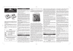
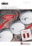
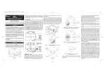
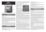
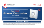
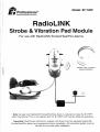
Professional
Model : EI17OR F
RadioLi N
Strobe & Vibration Pad Modul e
For use with RadioLlNK Smoke/Heat/Fire Alarm s
(Smoke / Heat / Fire Alarm
supplied separately)
Note : At least one RadioLlNK Smoke/Fire/Heat Alarm is required to make the .Ei17ORF
Alarm operational . This is not supplied with the Ei170RF and must be obtained separately .
Important : Read these instructions, together with those from the separate RadioLlN K
Smoke/Heat/Fire alarms and accessories before installation . All instruction leaflets must be
left with the end user after installation .
The Ei170RF is for use with the following Ei RadioLINK Smoke/Fire/Heat Alarms and Accessories .
Mains Multisensor/Smoke/Heat/Fire Alarms :
Ei2110, Ei160RC & Eli 40 Series Alarms in conjunction with an Ei168RC RadioLINK Base .
attery Powered Smoke / Heat Alarms :
Ei3100RF, Ei3103RF, Ei3105RF, Ei405, Ei405TY, Ei605C (with RF module), Ei605TYC (with RF module) .
Accessories :
E1407 Manual Call Point, Ei410 Remote Control (portable), Ei411 H Remote Control (wall mounted) ,
Ei428 Relay Module, E1408 Switched Input Module, Eli70RFS Strobe Pane l
This leaflet describes the installation of the Ei170RF and its integration into a total RadioLlNK Fir e
Alarm System, incorporating a choice of Smoke/Fire/Heat Alarms and Accessories .
N .B . It is essential that the Ei170RF is connected to the mains to preserve its one-week battery
standby. Leaving the unit operating without mains connected will completely deplete the battery an d
possibly damage it . (If the Ei170RF is not being used for a prolonged period and cannot be left plugge d
in to the mains, then disconnect the battery) .
Locatio n
The Strobe Module should normally be fixed such that the internal strobe light can be seen from the bed ,
and the vibration pad can be placed under the mattress or pillow. It has to be powered from the main s
(230VAC) so a suitable socket or junction box must be available to which it can be permanently connected .
The back-up battery in the Strobe Module must not be exposed to excessive heat such as sunshine ,
heaters, fires or the like .
The associated RadioLINK Alarms and Accessories must be located and installed as described i n
their own instruction leaflets .
Strobe Module Ei170R F
The battery must first be installed in the Strobe Module . Open the rear compartment by squeezin g
together the two latches as shown in Figure lb, and lifting the cover off.
Squeez e
Her e
Channel s
for mains lead &
Vibration Pad:
(and accesso'rie s
if required)
Figure la
Figure l b
Squeeze as shown to ope n
battery compartment
Figure 2
Plug the battery into the socket at the rear of the battery compartment as shown in Figure 2 (whil e
holding the small latch on the battery plug, open) . Place the battery in the compartment ensuring th e
notch in the battery is used to leave clearance for the plug and sockets (see Figure 3) .
Battery
Clearanc e
Notc h
Figure 3
Shows battery orientation - Dress the battery leads as shown, replace the battery cover an d
push firmly down on the two latche s
The Strobe Module can be left on a table or permanently fixed to the wall using the screws and plasti c
plugs enclosed .
If fixing to a wall, the screws should be spaced 95mm (3 .7 inches) horizontally apart . The top screws wi l
be 70mm (2 .7 inches) below the top surface of the Strobe Module when installed . The template at th e
end - of this leaflet can be used to locate the screws accurately . The screws (large heads) should b f
screwed into the wall leaving a gap of approximately 4mm (O .15in) under the head . Fit the keyhole slot ;
on the back of the Strobe Module over the screw heads and slide the panel down vertically into positio n
The mains adaptor should then be- plugged into a socket (or permanently wired to a mains junction bo :
- see overleaf) . This mains socket must not be used for any other equipment and it must not be switche c
off . The mains plug . must be readily removable (so the mains can be disconnected if necessary) .
3
Ifconnectingto a mains Junction Box
It is preferable to permanently wire the unit into a mains junction box . In this case remove th e
plug and wire as follows .
Warning : If the plug is being removed and the unit is being wired to a junction box it should b e
installed by a qualified . electrician in accordance with the Regulations for Electrical Installation s
published by the Institute of Engineering & Technology (UK) BS7671 . Failure to install thi s
system correctly may expose the user to shock or fire hazards.
First remove the power to the circuit at the distribution board .
The mains lead wires are colour coded as follows :
Brown : Live
Blue : Neutra l
The wire which is coloured blue must be connected to the terminal/wire which is marked wit h
the letter N or coloured blue .
The wire which is coloured brown must be connected to the terminal/wire which is marked wit h
the letter L or coloured brown.
The apparatus is not to be earthed, so no connection is to be made to terminals or wires marke d
with the letter E, the symbol O or coloured green or green/yellow.
Vibration Pad Ei17 4
The primary vibration pad is supplied already plugged into its locking socket on the rear of the Ei170R F
Strobe Module (see Figured a) . Place the vibration pad under the pillow or mattress . It is important that
the person in the bed can feel the vibration – check it is sufficient to wake a person by lying on the be d
and pressing the test button on the Strobe Module – see also Section 4, Testing and Maintaining you r
System . Some mattresses may not transmit sufficient vibration, and in these cases it should be fitte d
under the pillow . Note : During testing, or in an actual alarm situation, the pad pulses on and off for
greater effect on sleepers .
The Strobe Module must not be exposed to dripping or splashing and items filled with liquids such a s
vases must not be placed on or above the apparatus .
This system uses radio to communicate between the Fire Alarms, Accessories and the Strobe Module .
It is set-up simply by putting all of the units into "House Code Mode" and letting them automaticall y
code with each other . This will "House Code" the installation so that they will not accidentally signal to ,
or be affected by, nearby systems.
The units will all communicate with each other (providing they are within range), as delivered i .e.
without any House Coding - however it is recommended that they are House Coded as follows :
3.1 .1 Install & power all the elements of the system .
3.1 .2 Press the House Code switch on all units – see individual instruction leaflets for switch locations .
On the Strobe Module, the House Code switch is pressed by means of small screwdriver (or similar ,
diameter of top less than 3mm), through the access hole on the top of the unit – see figure 4 .
3.1 .3 Press and hold the Strobe Module House Code button until the blue RadioLINK light comes on .
Release it and the light will flash every five seconds .
3.1 .4 When all units are set into `House Code Mode' they should signal to each other and set-up thei r
network automatically.
3.1 .5 Each unit will now flash its blue or amber light to show how many units it is RadioLINKED with . If the
Strobe Module is linked to just one smoke alarm they will both flash twice . With 6 units for example, 4 Smoke
Alarms, a Remote Control and the Strobe Module itself, each unit will flash six times (apart from the Remot e
Control, which does not have this feature) . A maximum of twelve RF units can be linked this way.
4
Clock Inpu t
(if required)
Main s
Indicator
Gree n
(main s
disconnected =
amber flash/
4 seconds)
Alarm
Red
Figure 4
li
3.1 .6 If some units flash less than the expected number of times, after being in House Code Mode fo r
over 10 minutes) (say four times on a six unit system) they are out of range of each other .
Follow the advice in the RadioLINK instructions supplied with the other alarms to resolve this .
3.1 .7 The units will automatically exit the House Code Mode after 30 minutes . However we recommen d
that you manually exit the House Code Mode by pressing and holding the House Code switch on th e
Strobe Module until the blue light turns on, then release . The blue light should stop flashing and a n
`exit House Code Mode' radio signal will be sent to all other units . Check that the amber/blue lights o n
all other units have stopped flashing . (if some units are still flashing it may indicate a problem with th e
radio communication to this unit, or that the particular RadioLINK unit (models Ei3100RF, Ei3103RF ,
Ei3105RF, Ei407, Ei410, Ei411 H & Ei408) does not have this automatic cancel House Code Mod e
feature and must be taken out of House Code Mode manually . Check instruction leaflet supplied wit h
the units . Manually exiting the House Code Mode reduces the risk of accidentally House Coding you r
RadioLINK Bases with nearby systems .
Note: When the blue or amber light has stopped flashing on a unit it is out of House Code Mode — d o
not press the House Code switch again as this will put it back into House Code Mode .
3.2 ADDING UNIT S
To add units to the system simply repeat the above procedure, i .e . put all into House Code Mode, ne w
as well as old units, and ensure that the number of flashes shown equals the number of units in th e
system . For the other RadioLINK components see their instruction leaflets .
3 .3 RESETTING HOUSE CODE S
Sometimes it is necessary to cancel the House Code learned i .e . to reset the units to the factor y
settings . To reset the Strobe Module to clear the House Codes, simply hold the House Code butto n
until the blue light illuminates solidly, then starts to flash and then stops flashing, then release th e
button, this will take about six seconds . For other RadioLINK components see their separat e
instruction leaflets .
4.1 AFTER INSTALLATIO N
4.1 .1 Check that all RadioLINK Alarms and Accessories are powered correctly .
4.1 .2 Check that the green light on the Ei17ORF Strobe Module is continuously lit .
4.1 .3 Press the test button on all RadioLINKED Smoke/Heat/Fire Alarms, Remote Controls an d
Manual Call Points in turn, and check that all other Smoke/Heat/Fire Alarms in the system alarm afte r
about 4 seconds and that the strobe and vibration pad activate . Also check that the RadioLIN K
accessories were operated .
N.B. Wait 12 seconds before testing the next unit or if you wish to repeat testing .
4 .1 .4 Press the Strobe Module test button . Check the vibration pad pulses, the strobe flashes and th e
red alarm light on the Strobe Module flashes (this will also cause the Smoke/Heat/Fire Alarms t o
sound and also their red lights to flash rapidly) .
4.2 DAILY&WEEKLY TESTIN G
Check daily that the vibration pad is in its correct position under the pillow or mattress by pressing th e
test button on the Strobe Module . Also check daily that the green light on the Strobe Module is o n
constantly. We recommend that you test your system weekly by pressing all the smoke/heat/fire alar m
test buttons and checking that the vibration pad and strobe light operate .
Check the Strobe Module indicator lights as follows (see figure 4 )
4 .2 .1 Green mains power should be constantly on . If it is off check that it is plugged into the mains ,
that the socket is not switched off, fuses, circuit breakers etc . If the mains is off, the green light will b e
off and the unit will be running on the rechargeable battery . The green light will be replaced by a n
amber flash every 4 seconds to indicate battery is satisfactory . When this amber flash stops, th e
battery is depleted and the mains should be reinstated (If the mains cannot be reinstated at this time ,
the depleted battery should be removed, until the mains can be re-connected) .
4 .2.2 Press the Test button on the Strobe Module and check that the strobe flashes, the red alarm ligh t
flashes and that the blue RadioLINK light illuminates on for about 3 seconds indicating the radio tes t
signal is being sent to the Smoke/Fire/Heat alarms and any accessories .
4.2.3 Check that the amber fault light is not flashing every 4 seconds . If it is check that the primar y
vibration pad is connected firmly to the socket with its plug latched (see figure 1) . If the primar y
vibration connection is satisfactory, it is probably indicating that the battery is depleted . Connect th e
unit to the mains and check after 24 hours that the amber fault light has ceased flashing .
4 .3 PERIODIC TESTING OF RECHARGEABLE BATTER Y
4 .3.lThe rechargeable battery can take up to 20 hours to charge when the unit, is first powered up . It i s
then maintained in a fully charged state by continuous trickle charge . In the event of a mains failure th e
battery will power the system in standby for a week and then be capable of at least 4 minutes of alarm .
If the mains fails, the green light is extinguished and the amber light flashes every 4 seconds on th e
Strobe Module to indicate it is on battery power . The amber light will also flash every 4 seconds if th e
battery is almost depleted . Both the amber lights will go off to indicate the battery is depleted and the uni t
is totally unpowered .The battery will last 5 years in normal use provided it is not exposed to extremes o f
temperature for prolonged periods, or fully discharged & charged a large number of times .
We recommend that the functioning of the rechargeable battery is checked at least yearly as follows :4.3 .2 Ensure the Strobe Module has been mains powered for at least the previous 20 hours for th e
battery to charge .
4.3.3 Turn off the mains power to the unit by unplugging it or switching off the circuit at the distributio n
board. Check that the green light goes off and the amber light starts to flash .
4.3.4 Press the Strobe Module test button for 20 seconds and check the strobe flashes brightly, th e
pad vibrates strongly and that all the RadioLINK alarms trigger . Check that the red alarm light-flashes
while the test button is pressed . (Cover the strobe light with a card to stop this dazzling you while
looking at the red light) . If the red light goes off, or if the strobe is weak, or if the vibration pad is weak ,
6
the battery will need to be replaced . Contact the nearest address in this leaflet for advice about gettin g
a replacement. The battery also needs to be replaced if it is over 5 years old (see "replace battery by "
date on side panel) . To remove the battery reverse the instructions in the first part of section 2 . Contact
nearest address at the end of this leaflet on obtaining a replacement battery .
Replace the entire Strobe Module after 10 years operation . (see "replace unit by" date on side panel) .
If the units fail any of the above tests after installation, the system has probably been incorrectl y
installed and/or all units are not House Coded correctly . Check carefully that all units are powered . If
the power lights on any of the mains units are not on constantly, or flashing once every 45 seconds o n
battery powered units, check the connections to the mains and/or the connections to the batteries .
(See individual unit instruction leaflets if necessary) . For mains units check that the power is not off
(i .e. due to a tripped circuit breaker or fuse) .
The wiring to the primary vibration pad is monitored and if the vibration pad is removed or if its wiring i s
open circuit, the strobe and the amber fault light will flash (this may take up to approximately 45 seconds) .
There are no user serviceable parts in this unit (apart from the battery) . If the unit (apart from th e
battery) is thought to be defective, it must be returned to the nearest address at the end of this leafle t
for repair or replacement (see "Five Year Guarantee" section) .
Some troubleshooting items (including RF links) are specific to individual units and may not be covere d
in this leaflet. In these cases the more comprehensive unit leaflet should be consulted .
OTHER FEATURE S
Strobe & Vibration Pad Module - Auxiliary Outputs - AUX 1 & AUX 2 : The two auxiliary outputs are
activated when the Strobe Module is in alarm . The Aux 1 socket can supply up to 180mA at 12 Volts .
The AUX 2 socket can supply up to 20mA at 12 Volts .
N .B. The AUX 2 socket can be used for low power devices such as pager trigger inputs .
Note: As supplied the two auxiliary sockets AUX . 1 and AUX . 2 are protected by latched plastic plugs whic h
must be removed before the auxiliary devices can be plugged in (see figure 5) . These plugs can be remove d
by pressing the latch lever (on the side nearest the "AUX" marking) before gently pulling the plug off .
"Clock Input" Socket : A suitable alarm clock signal (with a 5 to 24 Volts AC or DC output –
electrically isolated from the mains supply) can be connected to this input socket with a 3 .5mm mon o
jack plug . (see figure 4) When the alarm clock triggers, the vibration pad turns on continuously (i .e . it
is not pulsed) to wake the person, but the internal strobe or auxiliary outputs are not activated . Thi s
lets the user know it is a wake-up call and not a fire .. Therefore the user needs only one vibration pa d
under their pillow or mattress – rather than two, one for the Fire Alarm and one for the alarm clock .
ACCESSORIE S
Ei178 - Auxiliary Strobe: (draws 180mA) . Supplied with 10m of cable and a suitable plug fo r
connection to the auxiliary socket . It should be plugged into AUX 1 . It. . can be located, for example ,
where it is readily seen during the day (e .g . downstairs hallway) .
Ei174 - Auxiliary Vibration Pad : (draws 120mA) . Supplied with 5m of cable and a suitable plug fo r
connecting to the auxiliary socket . It should be plugged into AUX 1 .
Ei410 - RadioLINK Remote Control (portable) : The Remote Control Ei410 allows you to Test, Hush o r
Locate suitable RadioLlNK Smoke/Fire/Heat Alarms .
Ei411 H - RadioLINK Remote Control (wail mounted) : This wall mounted switch allows you to Test ,
Hush or Locate suitable RadioLINK Smoke/Fire/Heat Alarms . (Note : the Strobe Module Ei17OR C
ignores a RadioLINK LOCATE message and will continue to flash the strobe and drive the vibratio n
pad as long as it gets an RF alarm signal) .
Ei407 - RadioLINK Manual Call Point : This allows remote triggering of RadioLINK alarms / accessorie s
and is ideal where emergency situations are identified and which require immediate evacuation .
7
Ei428 - RadioLINK Relay Module : This module contains a set of relay contacts that switch upo n
receipt of an alarm signal from suitable RadioLINK Smoke/Fire/Heat Alarms .
EHi70RFS: An additional RadioLINK Strobe Module, without a vibration pad (i .e. Strobe only) is availabl e
for use in a day rooms etc . to give a visual fire warning.It is supplied with a blanking plug, without a cabl e
attached, which connects into the primary vibration pad socket (marked "PAD") to prevent the amber faul t
light and strobe activating, indicating a fault (which would occur if the socket was left empty) .
Ei408 - RadioLINK Switched Input Module: This allows panels or other devices with Volt-free relay
outputs to trigger the RadioLlNK system, including the Ei170RF.
Primary Vibration Pa d
Remove
protectio n
plug befor e
connectin g
accessories
Template for Mounting Screw s
Drill Holes Her e
Figure 5
Ei Electronics guarantees this device for five years from the date of purchase against any defects tha t
are due to faulty materials or workmanship . This guarantee only applies to normal conditions of use an d
service, and does not include damage resulting from accident, neglect, misuse, unauthorise d
dismantling, or contamination howsoever caused . This guarantee excludes incidental and consequentia l
damage. If this device should become defective within the guarantee period, it must be returned to th e
nearest address given below, carefully packaged, with the problem clearly stated along with proof of th e
date of purchase . We shall at our discretion repair or replace the faulty unit .
The crossed out wheelie bin symbol that is on your
product indicates that this product should not be disposed
of via the normal household waste stream . Prope r
disposal will prevent possible harm to the environment o r
to human health . When disposing of this product please
separate it from other waste streams to ensure that it ca n
be recycled in an environmentally sound manner . Fo r
more details on collection and proper disposal, pleas e
contact your local government office or the retailer where
you purchased this product .
Aico Ltd . Mile End Business Park ,
Maesbury Rd, Oswestry, Shropshire SY10 8NN, U .K .
Tel : 0870 758 400 0
www.aico .co .u k
Ei Electronics . Shannon, Co Clare, Ireland .
Tel:+353 (0)61 471277
P/N B16308 RevO
©
Ei Electronics 2008
www.eielectronics.com