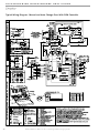
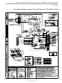
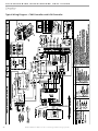
1
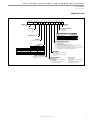
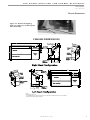
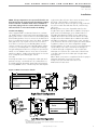
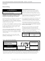
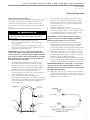
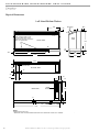
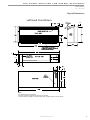
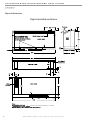
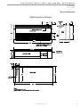
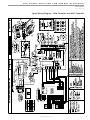
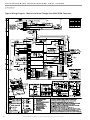
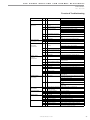
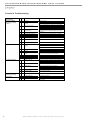
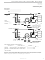
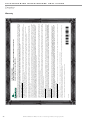
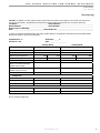
Console CCE Series Table of Contents Console 50Hz - hfc-407c Water-Source Heat Pumps Installation, Operation & Maintenance 97B0035N02 Revised: 08/13/10 Model Decoder General Information Inspection Introduction Storage Unit Protection Pre-Installation Chassis Dimensions Installation Supply and Return Hoses Installation of Supply and Return Piping Condensate Piping Electrical Wiring Optional Wall Mounted Thermostat Start-Up Preparation System Checkout Unit Start-Up Maintenance Physical Dimensions Physical Data Electrical Data Wiring Diagrams Matrix Wiring Diagrams Functional Troubleshooting Troubleshooting Form Warranty Start-Up Log Revision History 2 3 3 3 3 3 3 5 6 6 7 7 8 8 10 10 11 13 14 18 18 19 20 25 27 28 29 30 CLIMATEMASTER WATER-SOURCE HEAT PUMPS Consoles R e v. : 0 8 / 1 3 / 1 0 This Page Intentionally Left Blank 2 C l i m a t e M a s t e r W a t e r- S o u r c e H e a t i n g a n d C o o l i n g S y s t e m s THE SMART SOLUTION FOR ENERGY EFFICIENCY Consoles R e v. : 0 8 / 1 3 / 1 0 Model Decoder 1 2 3 4 5 6 7 8 9 10 11 12 13 14 15 CCE 0 7 B T C A S S C S R S Model Type Standard S = Standard CCE = Console Piping Connections Unit Size R = Right Piping L = Left Piping 07 09 12 15 19 Water Circuit Options None Motorized Water Valve Autoflow (2.25 Gpm/Ton) Autoflow (3.0 Gpm/Ton) Motorized Water Valve & Afr (2.25) Motorized Water Valve & Afr (3.0) Revision Level Voltage T = 220-240/50/1 - R407C ACO Unit Mounted T-Stat Remote Mounted T-Stat Remote Mounted T-Stat w/LON Remote Mounted T-Stat w/MPC F G H J K L M N P Q R T A = Copper Water Coil w/ Coated Air Coil C = Copper Water Coil J = Cupro-nickel W ater Coil w/ Coated Air Coil N = Cupro-nickel W ater Coil V = Copper Water Coil w/E-Coated Air Coil & Extended Range Insulation E = Copper Water Coil w/Extended Range Insulation M = Cupro-nickel Water Coil w/ Coated Air Coil & Extended Range Insulation F = Cupro-nickel Water Coil w/Extended Range Insulation CE Compliant CXM DXM E F J K Q G T U H S A B C D E Heat Exchanger Options Controls MCO Unit Mounted T-Stat Sweat IPT EPT Subbase V S = 3” Subbase D = 3” Subbase w/Motorized Damper G = 5” Subbase H = 5” Subbase w/Motorized Damper N = None Power Termination A = Field Connected (Hard Wire) F = Disconnect Cabinet Insulation With UltraQuiet M = Bottom Return D = Bottom Return w/Locking Control Door B = Front Return E = Front Return w/Locking Control Door C = No Cabinet Chassis Only Without UltraQuiet S = Bottom Return L = Bottom Return w/Locking Control Door F = Front Return G = Front Return w/Locking Control Door N = No Cabinet Chassis Only Rev.: 24 June, 2010 c l i m a t e m a s t e r. c o m 3 CLIMATEMASTER WATER-SOURCE HEAT PUMPS Consoles R e v. : 0 8 / 1 3 / 1 0 General Information Inspection Upon receipt of shipment, carefully check the shipment against the bill of lading. Verify all CCE units have been received. Inspect each unit for damage. Be certain the carrier makes proper notation on the delivery receipt of all shortages and noticeable damage and he completes a Carrier Inspection Report. Concealed damage not discovered during unloading must be reported to the carrier within fifteen (15) days of receipt of shipment. NOTE: It is the responsibility of the purchaser to file all necessary claims with the carrier. Notify the ClimateMaster Traffic Department within fifteen (15) days of receipt of all damaged shipments. Introduction ClimateMaster Console Air Conditioner Water Source Heat Pump units are decentralized room terminals designed for field connection to a closed-circuit piping loop. They are offered in capacities ranging from 2-5.6 kW cooling. Units must be installed indoors and are typically installed in perimeter zones, usually under windows. Supply air is discharged directly into the conditioned space through discharge grille located in the top of the unit. Storage CAUTION: DO NOT store or install CCE units in corrosive environments or in locations subject to temperature or humidity extremes (e.g., attics, garages, rooftops, etc.). Corrosive conditions and high temperature or humidity can significantly reduce performance, reliability, and service life. Always move units in an upright position. Tilting units on their sides may cause equipment damage. Upon the arrival of the equipment at the job site, immediately store units in their shipping cartons in a clean, dry area. Store units in an upright position at all times. Stack units a maximum of 3 units high. Use pallets to separate each layer of units. Do not remove equipment from shipping cartons until equipment is required for installation. Unit Protection Cover CCE units on the job site with either shipping cartons, vinyl film, or an equivalent protective covering. Cap the open ends of pipes stored on the job site. In areas where painting, plastering, or the spraying of fireproof material has not been completed, all due precautions must be taken to avoid physical damage to the units and contamination by foreign material. Physical damage and contamination may prevent proper startup and may result in costly equipment clean-up. Examine all pipes, fittings, and valves before installing the system components. Remove any dirt found on these components. 4 Pre-Installation Installation, operation and maintenance instructions are provided with each unit. Before unit start-up, read all manuals and become familiar with the unit and its operation. Thoroughly check out the system before operation. Complete the inspections and instructions listed below to prepare a CCE unit for installation. 1. Compare the electrical data on the unit nameplate with ordering and shipping information to verify that the correct unit has been shipped. 2. Keep both the chassis and cabinet covered with the shipping carton until all plastering, painting, and finish work is complete and it is time to install the chassis and cabinet. 3. Verify that the refrigerant tubing is free of kinks or dents, and that it does not touch other unit components. 4. Inspect all electrical connections. Connections must be clean and tight at the terminals. � WARNING! � To avoid equipment damage, do not use these units as a source of heating or cooling during the construction process. The mechanical components and filters used in these units quickly becomes clogged with construction dirt and debris which may cause system damage. To avoid the release of refrigerant into the atmosphere, the refrigerant circuit of this unit must only be serviced by technicians which meet local, state and federal proficiency requirements. All refrigerant discharged from this unit must be recovered without exception. Technicians must follow industry accepted guidelines and all local, state and federal statutes for the recovery and disposal of refrigerants. When a compressor is removed from this unit, system refrigerant circuit oil will remain in the compressor. To avoid leakage of compressor oil, the refrigerant lines of the compressor must be sealed after it is removed. � WARNING! � WARNING! The installation of water source heat pumps and all associated components, parts, and accessories which make up the installation shall be in accordance with the regulations of ALL authorities having jurisdiction and MUST conform to all applicable codes. It is the responsibility of the installing contractor to determine and comply with ALL applicable codes and regulations. C l i m a t e M a s t e r W a t e r- S o u r c e H e a t i n g a n d C o o l i n g S y s t e m s THE SMART SOLUTION FOR ENERGY EFFICIENCY Consoles R e v. : 0 8 / 1 3 / 1 0 Chassis Dimensions Figure 1a : Remove 4 shipping bolts on compressor isolation plate. (Not all models) Chassis Dimensions 1/2” FPT or 1/2” MPT 1/2” FPT or 1/2” MPT Notes: All dimensions are in mm. *For installed dimension, add to dimension shown 74mm with 3” subbase and 124mm for 5” subbase. **Dimension reduced by fitting if selected. c l i m a t e m a s t e r. c o m 5 CLIMATEMASTER WATER-SOURCE HEAT PUMPS Consoles R e v. : 0 8 / 1 3 / 1 0 Installation The installation of ConsoleWater Source Heat Pumps and all associated components, parts and accessories that make up the installation shall be in accordance with the regulations of ALL Authorities having jurisdiction and MUST conform to all applicable Codes. It is the responsibility of the Installing Contractor to determine and comply with ALL applicable Codes and Regulations. NOTE: An Installation Checklist is provided in this manual. Complete this checklist after all installation procedures are completed. A periodic maintenance checklist provided in the Maintenance section outlines recommended maintenance schedules. A Start-Up Inspection Log is also included at the end of this manual to encourage thorough unit checkout at initial start-up. These checklists are not a substitute for the detailed information found in the Installation section of this manual. 1. CCE units are typically installed along an outside wall of the room. Provide adequate space in front of the unit for service and maintenance. Locate the Console Air Conditioner so that it provides adequate air circulation throughout the room. 2. Unpack the CCE Unit from the shipping carton. Remove the front cabinet by lifting up and away from the backplate. Protect the cabinet from damage during installation by returning it to its original vinyl pack until required. 3. Remove compressor isolation plate shipping screws (4) as shown in Figure 1a. 4. Using a carpenter's square and a level, ensure the unit is level. Shim the unit if necessary to assure proper installation. CAUTION: Poor or inadequate installation may result in noisy unit operation or unattractive installation. 5. Select the proper fasteners to connect the backplate securely to the wall. 6. Fasten the backplate onto the wall through the screw holes located in the back flange. Secure the subbase in place. 7. Make all necessary electrical connections as described in the Electrical Wiring section of this manual. Consult the wiring diagram to ensure proper hook-up. 8. Connect the final piping as described in the Supply and Return Piping and Condensate Piping section of the manual. Install shut-off valves, piping and/or hoses and other accessories as specified. 9. Before making the final water connections, flush the system as described in the Start Up section of this manual. After flushing the system, connect piping and hoses to the proper supply, return and condensate connections of the unit. 6 NOTE: When necessary, use adapters to connect hoses. 10. Install any other system components as required following manufacturer's instructions. 11. After Start-up, reinstall the front cabinet by carefully lowering the front cabinet over the chassis onto the backplate. Supply and Return Hoses Optional pressure-rated hose assemblies are available for use with ClimateMaster CCE Units. Use the following guidelines when installing supply and return hose assemblies. 1. Install supply and return hoses fitted with swiveljoint fittings at one end to prevent the hose from twisting. 2. Use male adapters to secure the hose assembly to the unit and the riser. 3. Do not allow the hose to twist during installation. Twisting may damage the hose wall or the rubber compound. (Not all models) 4. Use pipe joint compound sparingly on the male pipe threads of the fitting adapters. 5. Prevent sealant from reaching the flared surfaces of the joint. 6. Do not use pipe joint compound when teflon thread tape is pre-applied to hose assemblies or when flared-end connections are used. 7. Maximum torque which may be applied to brass fittings is 30 ft-lbs. When a torque wrench is not used, tighten brass fittings finger-tight plus one quarter turn. 8. Tighten steel fittings as necessary. 9. Shut-off/balancing valves, flow indicators, and drain tees in the supply runout and return at each floor aid in loop balancing and servicing. CAUTION: Loop Fluids should be of good quality with no more than 0.50 ppm of chlorides w/ Cu (125 ppm w/ CuNi) to prevent corrosion and should also be filtered to a maximum 800 micron particle size to prevent erosion of the heat exchangers. Supply and Return Piping System piping MUST comply with all applicable codes. 1. Install a drain valve at the base of each supply and return riser to enable system flushing at start-up and during routine servicing. 2. Install shut-off/balancing valves and unions at each unit to allow unit removal for servicing. NOTE: If flex hoses are used, unions are not necessary. 3. Install strainers at the inlet of each system circulating pump. C l i m a t e M a s t e r W a t e r- S o u r c e H e a t i n g a n d C o o l i n g S y s t e m s THE SMART SOLUTION FOR ENERGY EFFICIENCY Consoles R e v. : 0 8 / 1 3 / 1 0 Installation NOTE: If loop temperatures are expected below the ambient dew point, the optional internal insulation package must be ordered. Insulation must also be installed on loop water piping on those sections which run through unheated areas or are located outside the building. Condensate Piping Unit is supplied with condensate drain hose, 15.9mm I.D. flexible plastic nonpressure-rated, protruding from piping side of unit. Connect this hose to building drain. Avoid making kinks in hose to ensure an unobstructed flow of condensate from the unit to the drain. DO NOT twist, pull hose out, or push excess hose into unit. If hose will not connect to your building drain several options include, relocate end of building drain, add to or cut hose, use hard plastic or copper elbow fittings for tight radii (put inside hose). Keep hose positioned within or over subbase area so hose does not interfer with front cabinet. Cabinet should not push or reroute hose. Clamp all joints watertight. Check for leaks. Internally the drain hose is clamped to drain pan and pitched correctly. Horizontal runs of condensate hose should be pitched downward 6mm (1/4 inch) minimum for every 300MM of hose. Avoid low points and unpitch- ing because dirt collects in these areas and may cause blockage. If blocked the condensate level in drain pan increases, when level gets too high, CCE unit has sensor switch that will shut unit off, overflow may still occur. Building drain connection if parallel with floor the height can be up to 38mm above subbase for proper pitch and correct drainage, up to 130mm above is allowable but drainage will be slower. When 65 to 130mm above the hose inside unit will act as a trap. Heights more than 130mm above subbase are NOT allowable (condensate overflow may occur). Check if your unit has a disconnect box option, this limits building drain locations. See unit Configuration pages. Field installation of a trap or vent is not required unless specified by local codes. CCE units are designed in a blow-through configuration. The condensate drain pan is located on the outlet side of the blower so that the pressure in the drain pan is higher than atmosphere. When drain connection is completed check for proper drainage and leaks. Correct if necessary. If trap is used, check and clean often. See Maintenance Instructions. Figure 1 Water Connection details 1/2” FPT or 1/2” MPT 1/2” FPT or 1/2” MPT Notes: All dimensions are in mm. *For installed dimension, add to dimension shown 74mm with 3” subbase and 124mm for 5” subbase. **Dimension reduced by fitting if selected. c l i m a t e m a s t e r. c o m 7 CLIMATEMASTER WATER-SOURCE HEAT PUMPS Consoles R e v. : 0 8 / 1 3 / 1 0 Electrical Wiring � WARNING! � To avoid possible injury or death due to electrical shock, open the power supply disconnect switch and secure it in an open position during installation. CAUTION: Use only copper conductors for field installed electrical wiring. Unit terminals are not designed to accept other types of conductors. All field installed wiring, including the electrical ground, MUST comply with the National Electrical Code as well as applicable local codes. In addition, all field low voltage wiring must conform to the Class II temperature limitations described in the NEC. Consult the unit wiring diagram located on the inside of the compressor access panel to ensure proper electrical hookup. The installing (or electrical) contractor must make the field connections shown in Figure 1 when using field supplied disconnect. Units have dual voltage (220-240V) control transformer. The units are shipped for 240V operation. Modify the transformer connection when the actual power supply is 220 volts. Refer to the unit wiring diagram for details of this procedure. Make all final electrical connections with a length of flexible conduit to minimize vibration and sound transmission to the building. Optional Wall-Mounted Thermostat CCE WSHP units are built with standard internal thermostats in either manual changeover (MCO) or automatic changeover (ACO) configuration. No external, field-installed low-voltage wiring is required. When desired, the unit can be furnished with a 24-volt control circuit which is field-wired to a ClimateMastersupplied accessory remote thermostat. Zone integrity must be maintained to efficiently control units or groups of units. Unless zones of control are considered and accounted for, adjacent units may operate in heating and cooling modes simultaneously. Low-voltage wiring between the unit and the wall thermostat must comply with all applicable electrical codes (i.e., NEC and local codes), and be completed before the unit is installed. Table 2 lists recommended wire sizes and lengths to install the thermostat. The total resistance of low-voltage wiring must not exceed 1 ohm. Any resistance in excess of 1 ohm may cause the control to malfunction because of high voltage drop. Table 2 - Recommended Thermostat Wire Sizes WIRE SIZE MAX. WIRE LENGTH* 18-Gauge 16-Gauge 14-Gauge 23 m 38 m 62 m *Length = Physical distance from thermostat to unit. Figure 1 Typical Field Installed Wiring CAUTION: USE COPPER CONDUCTORS ONLY TO PREVENT EQUIPMENT DAMAGE. A Field Supplied Disconnect Switch � WARNING! � DISCONNECT ELECTRICAL POWER SOURCE TO PREVENT INJURY OR DEATH FROM ELECTRICAL SHOCK. Heat Pump B Room Thermostat A= Two power wires on single-phase units: three power wires on three-phase units. B= 1 heat /1 cool / manual or Auto Change-over remote 24V thermostat. Note: All customer-supplied wiring to be copper only and must conform to NEC and local electrical codes. Wiring shown with dashed lines must be fieldsupplied and field-installed. "B" only required with systems employing remote mounted thermostats. 8 C l i m a t e M a s t e r W a t e r- S o u r c e H e a t i n g a n d C o o l i n g S y s t e m s THE SMART SOLUTION FOR ENERGY EFFICIENCY Consoles R e v. : 0 8 / 1 3 / 1 0 Start-Up Preparation System Cleaning and Flushing Cleaning and flushing the unit and system is the single most important step to ensure proper start-up and continued efficient operation of the system. Follow the instructions below to properly clean and flush the system: DO NOT FLUSH SYSTEM THROUGH THE UNIT! � WARNING! � To prevent injury or death due to electrical shock or contact with moving parts, open unit disconnect before servicing unit. 1. Verify that electrical power to the unit is disconnected and that the circulation pump is de-energized. 2. Connect the supply hose directly to the return riser valve. Use a single length of flexible hose as illustrated in Figure 2 below. NOTE: When one hose is too short to make the connection without exceeding the minimum bend radius of the hose, substitute two length of flexible hose joined together with a field-supplied, standard MPT coupling. Use the adapter provided with the hose kit as shown in Figure 3. 3. Fill the system with water, leaving the air vents open. Bleed all air from the system but do not allow the system to over flow. Check the system for leaks and make any required repairs. Adjust the water and air level in the expansion tank. 4. With strainers in place, start the pumps. Systematically check each vent to ensure that all of the air is bled from the system. 5. Verify that make-up water is available and adjusted to properly replace any space remaining when all air is evacuated. Pressure test and inspect the system for leaks and make any additional repairs required. Figure 2 6. Open the drain at the lowest point in the system. Verify that make-up water replacement rate equals rate of bleed. Continue to bleed the system until the water appears clean or for at least three hours whichever is longer. 7. Completely drain the system. 8. Refill the system with clean, chemically treated water. Since water varies for each locality, contact a local water treatment company for the correct cleaning chemicals to use in your area. CAUTION: To avoid possible damage to piping systems constructed of plastic piping, DO NOT allow loop temperature to exceed 43 °C. 9. Set the boiler to raise the loop temperature to approximately 29.4°C. Circulate the solution for a minimum of 8 to 24 hours. At the end of this period, shut off the circulating pump and drain the solution. Repeat system cleaning if necessary. 10. When the cleaning process is complete, remove the short-circuit hoses. Connect the hoses to the proper supply and return connections to the unit. Refill the system and bleed off all air. 11. Test the system pH with litmus paper. The system water should be slight alkaline (pH 7.5 to 8.5). Add chemicals as appropriate to maintain acidity levels. CAUTION: DO NOT use "Stop-Leak" or any similar chemical agent in this system. Addition of these chemicals to the loop water will foul the system and will inhibit unit operation. 12. When the system is successfully cleaned, flushed, refilled and bled, check the main system panels, safety cutouts and alarms. Set controls to properly maintain loop temperature. Figure 3 c l i m a t e m a s t e r. c o m 9 CLIMATEMASTER WATER-SOURCE HEAT PUMPS Consoles R e v. : 0 8 / 1 3 / 1 0 System Checkout When the installation is complete and the system is cleaned and flushed, follow the System Checkout procedure outline below. ❏ 1. ❏ 2. ❏ 3. ❏ 4. ❏ 5. ❏ 10 6. ❏ 7. ❏ 8. ❏ 9. Voltage: Ensure voltage is within the utilization range specifications of the unit compressor and fan motor. System Water Temperature: Ensure it is within an acceptable range to facilitate start-up. (When conducting this check, also verify proper heating and cooling set points.) System Water pH: Verify system water acidity. (pH = 7.5 or 8.5) Proper pH promotes the longevity of hoses and heat exchangers. System Flushing: Properly clean and flush system periodically. Ensure all supply and return hoses are connected end-to-end to facilitate system flushing and prevent fouling of the heat exchanger by system water. Water used in the system must be of potable quality and clean of dirt, piping slag, and chemical cleaning agents. Closed-Type Cooling Tower or Open Tower with Heat Exchanger: Check equipment for proper temperature set points and operation. Balanced Water Flow Rate to Heat Pump:: Verify the inlet and outlet water temperatures are recorded as each heat pump unit is started. This check will eliminate nuisance unit trip-outs resulting from water velocities which are either too low or too high; it can also prevent the occurrence of erosive water flow rates. Standby Pump: Verify the standby pump is properly installed and in operating condition. System Controls: To ensure no catastrophic system failures occur, verify system controls are functioning and the sequencing is correct. Freeze Protection for Water System: Verify freeze protection is provided for the outdoor portion of the loop water system. Inadequate freeze protection can lead to expensive tower and system piping repairs. CAUTION: To avoid equipment damage, DO NOT leave system filled with water in a building without heat during the winter unless anti-freeze is added to system water. Coax coils never fully drain by themselves and will freeze unless winterized with anti-freeze. ❏ 10. ❏ 11. ❏ 12 ❏ 13. ❏ 14. System Water Loop: Verify all air is bled from the system. Air in the system impedes unit operation and causes corrosion in the system piping. Unit Filters: To avoid unit damage and maximum performance, ensure the unit filter is clean. Unit Fans: Manually rotate fans to assure free rotation. Ensure fans are properly secured to the fan shaft. Do not oil fan motors on start-up since they are lubricated at the factory. System Control Center: To ensure control of the temperature set-points for operation of the system’s heat rejector and boiler, examine the system control and alarm panel for proper installation and operation. Miscellaneous: Note any questionable aspects of the installation. C l i m a t e M a s t e r W a t e r- S o u r c e H e a t i n g a n d C o o l i n g S y s t e m s THE SMART SOLUTION FOR ENERGY EFFICIENCY Consoles R e v. : 0 8 / 1 3 / 1 0 Unit Start-Up Use the procedure outlined below to initiate proper unit start-up: NOTE: This equipment is designed for indoor installation ONLY. � WARNING! � 6. When the disconnect switch is closed, high voltage is present in some areas of the electrical panel. Exercise caution when working with the energized equipment. 1. Adjust all valves to the full open position and turn on the line power to all heat pump units. 2. Operate each unit first in the cooling mode. Operate each heat pump in the heating cycle immediately after checking cooling cycle operation. A time delay will prevent the compressor from re-starting for approximately three minutes. Room temperature should be in the normal range (i.e., approximately 10-27°C DB. Loop water temperature entering the heat pumps should be at least 4°C but not in excess of 43°C. Refer to Table 3 for more specific information on the operating parameters of CCE units. NOTE: Three factors determine the operating limits of a CCE unit: (1) return air temperature, (2) water temperature and (3) ambient temperature. Whenever any one of these factors is at a minimum or maximum level, the other two factors must be at normal levels to ensure proper unit operation. Flow rates must be at ARI rated standards. 3. 5. Low Cooling - Disregard if your unit has only 1 fan speed. Select low fan. Airflow should decrease and compressor should operate. Unit cycles off - Slowly turn thermostat toward warmer position. Both fan and compressor should shut off when thermostat set point equals room temperature. Note: room temperature must be below 32°C or unit will not cycle off. Operating Limits Environment: This equipment is designed for indoor installation ONLY. Power Supply: A voltage variation of +/- 10% of nameplate utilization voltage is acceptable. CCE Unit Starting Conditions: CCE Units start and operate in an ambient of 10°C with entering air at 10°C, entering water at 16°C and with both air and water at the flow rates used in the ARI Standard 13256-1 rating test for initial start-up in winter. Table 3 Operating Limits Air Limits CCE Units Cooling Heating Min. Ambient Air 10° C 10° C Rated Ambient Air 27° C 19° C Max. Ambient Air 38° C 30° C Min. Entering Air 10° C 10° C Rated Entering Air db/wb 27/19° C 20° C Max. Entering Air db/wb 38/28° C 27° C Water Limits Min. Entering Water * -1° C * -6° C Normal Entering Water 30° C 21° C Max. Entering Water 43° C 32° C If units do not operate correctly refer to the troubleshooting section (pg. 11). If unit cannot be repaired, record on form on last page of this manual and continue with start-up procedure. Unit Start-up / Cooling 4. High Cooling -Turn the unit thermostat to the coolest position and turn the fan speed switch to "HI". If the unit has an optional MCO thermostat, set the selector switch to cool. Both the fan and compressor should run. Check for cool air delivery at unit grille 15 minutes after the unit is operating. List the identification number of any machines that do not function at this time. Check the elevation and cleanliness of the condensate lines; any dripping could be a sign of a blocked line. * Requires optional insulation package when operating below the dew point. Note: Minimum air and water conditions can only be used at ARI flow rates. CCE Units may have up to two values at maximum or minimum with all other parameters at normal conditions. NOTE: These operating limits are not normal for continuous operating conditions. It is assumed that such a start-up is for the purpose of bringing the building space to desired occupancy temperature. c l i m a t e m a s t e r. c o m 11 CLIMATEMASTER WATER-SOURCE HEAT PUMPS Consoles R e v. : 0 8 / 1 3 / 1 0 Unit Start-Up / Heating High Heat - Adjust the unit thermostat to the warmest setting and turn the fan speed switch to "HI". If the unit has an optional MCO thermostat, set the selector switch to heat. The blower should start immediately and after the time delay is complete the compressor will start. Once the unit has begun to run, check for warm air delivery at the unit grille. Again the installing contractor must list the serial number of any machine that does not function. Log the unit operating conditions at initial start-up for each unit to establish a permanent operating record. 8. Low Heat - Disregard if unit is only one speed. Select low fan. Airflow should decrease and compressor should continue to operate. 9. Unit Cycles Off - Slowly turn thermostat toward cooler position. Both fan and compressor should shut off when thermostat set point equals room temperature. Note room temperature must be above 19°C or unit will not cycle off. 10. Fan Only - Select fan speed. Only fan should operate. 11. Off - Unit should not operate 7. Troubleshooting 1. If the unit fails to operate, conduct the following checks: a. Check the voltage and current. They should comply with the electrical specifications described on the unit nameplate. b. Look for wiring errors. Check for loose terminal screws where wire connections have been made on both the line and low-voltage terminal boards. c. Check for dirty filters. A clogged filter will cause safety cutouts to stop unit operation. d. Check the supply and return piping. They must be properly connected to the inlet and outlet connections on the unit. e. If the fan fails to operate,check wiring and check to see that the fan wheel turns freely and that it is secured to the shaft. Also, determine whether the fan operates during both the heating and cooling modes. f. Check if circuit board is flashing a fault code. See CXM/DXM AOM for details. g. Check that the unit has not cycled off on thermostat. h. If the checks described above fail to reveal the problem and the unit still will not operate, contact a trained service technician to ensure proper diagnosis and repair of the equipment. 2. Record any unit that does not operate correctly. Use the form at the end of this manual. 12 C l i m a t e M a s t e r W a t e r- S o u r c e H e a t i n g a n d C o o l i n g S y s t e m s THE SMART SOLUTION FOR ENERGY EFFICIENCY Consoles R e v. : 0 8 / 1 3 / 1 0 Maintenance Perform the maintenance procedures outlined below at the intervals indicated . � WARNING! � To prevent injury or death due to electrical shock or contact with moving parts, open unit disconnect switch before servicing unit. FILTERS: Inspect filters. Establish a regular maintenance schedule. Clean/replace filters frequently depending on need. To remove the filter from the CCE unit, slide the filter out of its frame located in the return air opening at the bottom front of the unit. When re-installing the filter, use the slide-in rails of the filter frame to guide the filter into the proper position. CAUTION: To avoid fouled machinery and extensive unit clean-up, DO NOT operate units without filters in place. DO NOT use equipment as a temporary heating or cooling source during construction. CONDENSATE PANS: Check condensate drain pans for algae growth every three months. If algae growth is apparent, consult a water treatment specialist for proper chemical treatment. The application of an algaecide every three months will typically eliminate algae problems in most locations. Check condensate hose for leaks and blockage and correct any problems. FAN MOTORS: All units have lubricated fan motors. Fan motors should never be lubricated unless obvious, dry operation is suspected. Periodic maintenance oiling is not recommended because it will result in dirt accumulating on excess oil and cause eventual motor failure. Conduct annual dry operation check and amperage check to ensure amp draw is no more than 10% greater than that indicated by serial plate data. UNIT INSPECTION: Visually inspect the unit at least once a month. Pay special attention to hose assemblies. Repair any leaks and replace deteriorated hoses immediately. Note any signs of deterioration or cracking. COMPRESSOR: Conduct an amperage check annually on the compressor and fan motor. Amperage draw should not exceed normal full load amps. Maintain a log of amperage to detect deterioration prior to component failure. HEAT EXCHANGERS: Water Coil Maintenance – Generally water coil maintenance is not needed however, if the installation is located in a system with a known high dirt or debris content, it is best to establish with the owner a periodic maintenance schedule so the coil can be checked regularly. These dirty installations are a result of the deterioration of iron or galvanized piping or components in the system or open cooling towers requiring heavy chemical treatment and mineral buildup through water use. Should periodic coil cleaning be necessary, use standard coil cleaning procedures which are compatible with both the heat exchanger material and copper water lines. Generally, the more water flowing through the unit, the less chance for scaling, however flow rates over 0.0538 l/s per kW can produce water (or debris) velocities that can erode the heat exchanger wall and ultimately produce leaks. Safety Control Reset All ClimateMaster heat pumps are furnished with highpressure, low-pressure and low-temperature cutouts to prevent the machine from operating at abnormal conditions of temperature or water flow. The contacts of the high-pressure control used on CCE units is designed to open at 2600 kPa and automatically re-close at 2100 kPa. The CXM or DXM control monitors this and other functions such as refrigerant temperatures and pressures and condensate overflow and will interrupt unit heating or cooling operation. The machine must be reset manually. Reset is accomplished by pressing the STOP button and then pushing either HI HEAT, LO HEAT, HI COOL or LO COOL to restart the unit in the desired mode of operation. (The CCE unit can also be reset by opening and closing the supply power disconnect switch.) NOTE: If the unit must be reset more than twice, check the unit for a dirty filter, abnormal entering water temperature, inadequate or excessive water flow, and internal malfunctions. If the unit continues to cut out, contact a trained service technician. � WARNING! � When replacing the compressor contactor or lockout relay in a unit with electromechanical controls, use only ClimateMaster replacement parts. Substitution of other components may result in an inoperative safety circuit and may cause a hazardous condition. c l i m a t e m a s t e r. c o m 13 CLIMATEMASTER WATER-SOURCE HEAT PUMPS Consoles R e v. : 0 8 / 1 3 / 1 0 Physical Dimensions Left Hand Bottom Return 320 Discharge Air 38 88.9 30º Control Access Door Filter located inside and at top of air inlet area. Push tabs back and down to release filter for replacement. SIDE VIEW FRONT VIEW 607 48 Air Inlet AIR INLET AREA 851 44.5 1219 292 305 1219 254 L.H. Pipe & Electric Area BOTTOM VIEW 19 40 25 89 114 25 REAR ACCESS REAR VIEW 533 508 41 DAMPER OPENING* 298 15 *74 251 1219 Notes: All Dimensions are in mm * Dimension with 76.2 mm subbase. Add 50.8 mm to dimension shown for 5” subbase 14 C l i m a t e M a s t e r W a t e r- S o u r c e H e a t i n g a n d C o o l i n g S y s t e m s . *74 THE SMART SOLUTION FOR ENERGY EFFICIENCY Consoles R e v. : 0 8 / 1 3 / 1 0 Physical Dimensions Left Hand Front Return 89 ° 13 292 (Note 2) 19 105 L.H. (NOTE 2) Notes: 1. All Dimensions are in millimeters. 2. Access is reduced if optional disconnect box is selected. 3. Optional autoflow regulator, motorized water valve, and disconnect box are not shown. c l i m a t e m a s t e r. c o m 15 CLIMATEMASTER WATER-SOURCE HEAT PUMPS Consoles R e v. : 0 8 / 1 3 / 1 0 Physical Dimensions Right Hand Bottom Return 251 . 16 Add 50.8 mm to dimension shown for 5” subbase C l i m a t e M a s t e r W a t e r- S o u r c e H e a t i n g a n d C o o l i n g S y s t e m s THE SMART SOLUTION FOR ENERGY EFFICIENCY Consoles R e v. : 0 8 / 1 3 / 1 0 Physical Dimensions Right Hand Front Return º c l i m a t e m a s t e r. c o m 17 CLIMATEMASTER WATER-SOURCE HEAT PUMPS Consoles R e v. : 0 8 / 1 3 / 1 0 Physical Data Physical Data 12.7 Electrical Data 18 C l i m a t e M a s t e r W a t e r- S o u r c e H e a t i n g a n d C o o l i n g S y s t e m s THE SMART SOLUTION FOR ENERGY EFFICIENCY Consoles R e v. : 0 8 / 1 3 / 1 0 Wiring Diagram Matrix All wiring diagrams can be located on the web at climatemaster.com Model CCE07 - 19 Refrigerant R-407C Wire Diagram Part Number Electrical Control 96B0099N60 CXM-ACO/MCO 96B0099N61 CXM-REM 96B0099N62 CXM-LON 96B0099N63 96B0100N60 96B0100N61 220-240/50/1 CXM-MPC DXM-ACO/MCO Agency CE DXM-REM 96B0100N62 DXM-LON 96B0100N63 DXM-MPC c l i m a t e m a s t e r. c o m 19 CLIMATEMASTER WATER-SOURCE HEAT PUMPS Consoles R e v. : 0 8 / 1 3 / 1 0 Typical Wiring Diagram - Manual and Auto Change Over With CXM Controller 20 C l i m a t e M a s t e r W a t e r- S o u r c e H e a t i n g a n d C o o l i n g S y s t e m s THE SMART SOLUTION FOR ENERGY EFFICIENCY Consoles R e v. : 0 8 / 1 3 / 1 0 Typical Wiring Diagram - Remote Mounted Thermostat With CXM Controller c l i m a t e m a s t e r. c o m 21 CLIMATEMASTER WATER-SOURCE HEAT PUMPS Consoles R e v. : 0 8 / 1 3 / 1 0 Typical Wiring Diagram - CXM Controller with LON Controller 22 C l i m a t e M a s t e r W a t e r- S o u r c e H e a t i n g a n d C o o l i n g S y s t e m s THE SMART SOLUTION FOR ENERGY EFFICIENCY Consoles R e v. : 0 8 / 1 3 / 1 0 Typical Wiring Diagram - CXM Controller with MPC Controller c l i m a t e m a s t e r. c o m 23 CLIMATEMASTER WATER-SOURCE HEAT PUMPS Consoles R e v. : 0 8 / 1 3 / 1 0 Typical Wiring Diagram - Manual and Auto Change Over With DXM Controller 24 C l i m a t e M a s t e r W a t e r- S o u r c e H e a t i n g a n d C o o l i n g S y s t e m s THE SMART SOLUTION FOR ENERGY EFFICIENCY Consoles R e v. : 0 8 / 1 3 / 1 0 Functional Troubleshooting Fault Htg Clg Possible Cause Main power Problems X HP Fault-Code 2 High pressure Solution X Green Status LED Off Check Line Voltage circuit breaker and disconnect Check for line voltage between L1 and L2 on the contactor Check for 24VAC between R and C on CXM/DXM Check primary/secondary voltage on transformer Check pump operation or valve operation/setting Check water flow adjust to proper flow rate X Reduced or no water flow in cooling X Water Temperature out of range in Bring water temp within design parameters cooling X Reduced or no Air flow in heating Check for dirty air filter and clean or replace Check fan motor operation and airflow restrictions Dirty Air Coil- construction dust etc. X Air Temperature out of range in heating Bring return air temp within design parameters Overcharged with refrigerant Check superheat/subcooling vs typical operating condition table Bad HP Switch Insufficient charge Check switch continuity and operation. Replace Check for refrigerant leaks Too high of external static. Check static vs blower table X X X X LP/LOC Fault-Code 3 X X Low Pressure/Loss of Charge X Compressor pump down at startup Check charge and start-up water flow FP1 Fault - Code 4 X Reduced or no water flow Check pump operation or water valve operation/setting in heating Plugged strainer or filter. Clean or replace. X Inadequate anti-freeze level Check antifreeze density with hydrometer X Improper temperature limit setting (30°F vs 10°F [-1°C vs -12°C]) Clip JW3 jumper for antifreeze (10°F [-12°C]) use Water Coil low temperature limit Check water flow adjust to proper flow rate X Water Temperature out of range Bring water temp within design parameters X X Bad thermistor Reduced or no Air flow in cooling Check temp and impedance correlation per chart Check for dirty air filter and clean or replace Check fan motor operation and airflow restrictions Too high of external static. Check static vs blower table X Air Temperature out of range Too much cold vent air? Bring entering air temp within design parameters X Improper temperature limit setting (30°F vs 10°F [-1°C vs -12°C]) Normal airside applications will require 30°F [-1°C] only X X Bad thermistor Check temp and impedance correlation per chart X X X X X Blocked Drain Improper trap Poor Drainage X Moisture on sensor Check for blockage and clean drain Check trap dimensions and location ahead of vent Check for piping slope away from unit Check slope of unit toward outlet Poor venting. Check vent location Check for moisture shorting to air coil X X Plugged Air Filter Replace Air Filter X X Restricted Return Air Flow X X Under Voltage Find & eliminate restriction. Increase return duct and/or grille size. Check power supply and 24VAC voltage before and during operation. Check power supply wire size Check compressor starting. Need hard start kit? X FP2 fault - Code 5 Air Coil low temperature limit Condensate Fault-Code 6 Over/Under VoltageCode 7 (Auto resetting) Check 24VAC and unit transformer tap for correct power supply voltage X X Over Voltage Check power supply voltage and 24VAC before and during operation. Check 24VAC and unit transformer tap for correct power supply voltage Unit Performance Sentinel-Code 8 X No Fault Code Shown Unit Short Cycles Only Fan Runs Heating mode FP2>125°F [52°C] Check for poor air flow or overcharged unit. X Cooling Mode FP1>125°F [52°C] OR FP2< 40ϒF [4ϒC] Check for poor water flow, or air flow X X No compressor operation See "Only fan operates" X X Compressor Overload Check and Replace if necessary X X X X X X Control board Dirty Air Filter Unit in "Test Mode" X X Unit selection X X Compressor Overload Reset power and check operation Check and Clean air filter Reset power or wait 20 minutes for auto exit. Unit may be oversized for space. Check sizing for actual load of space. Check and Replace if necessary X X X X Thermostat position Unit locked out X X Thermostat wiring X X Compressor Overload c l i m a t e m a s t e r. c o m Insure thermostat set for heating or cooling operation Check for lockout codes. Reset power. Check compressor overload. Replace if necessary. Check thermostat wiring at heat pump. Jumper Y and R for compressor operation in test mode. 25 X Unit Doesn't Operate in X Thermostat wiring X Reversing Valve X Thermostat setup X Thermostat wiring X Thermostat wiring Check thermostat wiring at heat pump. Jumper Y and R for compressor operation in test mode. Set for cooling demand and check 24VAC on RV coil and at CXM/DXM board. If RV is stuck, run high pressure up by reducing water flow and while operating engage and disengage RV coil voltage to push valve. Cooling C LIMATEMASTER WATER-SOURCE HEAT PUMPS Consoles R e v. : 0 8 / 1 3 / 1 0 Functional Troubleshooting Performance Troubleshooting Insufficient capacity/ Not cooling or heating properly High Head Pressure Htg Clg Possible Cause X X X Check for 'O' RV setup not 'B' Check O wiring at heat pump. Jumper O and R for RV coil 'Click'. Put thermostat in cooling mode. Check for 24VAC on O (check between C and O); check for 24VAC on W (check between W and C). There should be voltage on O, but not on W. If voltage is present on W, thermostat may be bad or wired incorrectly. Solution Dirty Filter Replace or clean in heating Check fan motor operation and airflow restrictions Too high of external static. Check static vs blower table Check for dirty air filter and clean or replace Check fan motor operation and airflow restrictions Too high of external static. Check static vs blower table Check supply and return air temperatures at the unit and at distant duct registers if significantly different, duct leaks are present Check superheat and subcooling per chart Check superheat and subcooling per chart. Replace. Perform RV touch test Check location and for air drafts behind stat Recheck loads & sizing check sensible clg load and heat pump capacity Reduced or no Air flow Check for dirty air filter and clean or replace X Reduced or no Air flow in cooling X X Leaky duct work X X X X X X X Low refrigerant charge Restricted metering device Defective Reversing Valve Thermostat improperly located X X Unit undersized X X Scaling in water heat exchanger Perform Scaling check and clean if necessary X X Inlet Water too Hot or Cold Check load, loop sizing, loop backfill, ground moisture. Reduced or no Air flow in heating Check for dirty air filter and clean or replace Check fan motor operation and airflow restrictions X Too high of external static. Check static vs blower table X X Low Suction Pressure X X X X X X X X X X High humidity 26 Check pump operation or valve operation/setting Check water flow adjust to proper flow rate Check load, loop sizing, loop backfill, ground moisture. Bring return air temp within design parameters Scaling in water heat exchanger Unit Overcharged Non-condensables insystem Restricted metering device Reduced water flow in heating Perform Scaling check and clean if necessary Check superheat and subcooling. Reweigh in charge Vacuum system and reweigh in charge Check superheat and subcooling per chart. Replace. Check pump operation or water valve operation/setting Plugged strainer or filter. Clean or replace. Check water flow adjust to proper flow rate Water Temperature out of range Bring water temp within design parameters X Reduced Air flow in cooling X Air Temperature out of range X Insufficient charge Check for dirty air filter and clean or replace Check fan motor operation and airflow restrictions Too high of external static. Check static vs blower table Too much cold vent air? Bring entering air temp within design parameters Check for refrigerant leaks X Too high of air flow Check fan motor speed selection and airflow chart X X Poor Performance Too high of air flow X Unit oversized See 'Insufficient Capacity' Check fan motor speed selection and airflow chart Recheck loads & sizing check sensible clg load and heat pump capacity X Low discharge air temperature in heating Reduced or no water flow in cooling Inlet Water too Hot Air Temperature out of range in heating C l i m a t e M a s t e r W a t e r- S o u r c e H e a t i n g a n d C o o l i n g S y s t e m s THE SMART SOLUTION FOR ENERGY EFFICIENCY Location: ________________________ Consoles R e v. : 0 8 / 1 3 / 1 0 Model Number: ________________________ Serial Number: ________________________ Date: ________________________ Troubleshooting Form Packaged Unit Refrigeration Schematic Location: ________________________ Customer: _____________________________________ Antifreeze: ________________________ Model Number: ________________________ Serial Number: ________________________ Model#: ________________________ Serial#: ________________ Loop type: _______________ Complaint:Date: ________________________________________________________________________ ________________________ HEATING CYCLE ANALYSIS _____________ Antifreeze: ________________________ kPa Serial#: ________________ Loop type: _______________ °C Refrigerant Type: R-407C AIR ________________________________________________ °C °F COMPRESSOR COAX DISCHARGE SUCTION Comp Amps: _______ °C COMPRESSOR Total Amps: ________ °C °C °C FLASH FP1 DISCHARGE GAS LINE SENSOR FP2: HEATING LIQUID LINE HWG °C kPa WATER IN °F FP1 SENSOR PSI COOLING CYCLE ANALYSIS °F °F PSI WATER IN PSI WATER OUT kPa °C kPa WATER OUT °F °F SAT Look up pressure drop in I.O.M. or spec. catalog to determine flow rate. SAT kPa SAT °C Look up pressure drop in I.O.M. or AIR spec. catalog to determine flow rate. COIL °C °C PSI SUCTION SAT COMPRESSOR °F EXPANSION VALVE SUCTION COAX DISCHARGE COMPRESSOR °C °C °C DISCHARGE SIDE FP1: CLG FP2: FLASH OTHER OF FILTR DR LIQ LINE GAS LINE HWG COAX ON FILTER DRIER* °C °C kPa WATER IN °F F DE DR SAT EXPANSION VALVE Voltage: ________ COAX SUCTION °C PSI ON FILTER DRIER* E COIL SAT °F FP1: CLG LIQ LINE ection = °F °F PSI HeatPSI of Extraction PSI(Absorption) WATER IN WATER OUT SAT PSI °C kPa WATER OUT SAT Look up pressure drop in I.O.M. or spec. catalog to determine flow rate. or Heat of Rejection = † ________ flow rate ( l/sLook diff. ) x up ________ temp. pressure drop in(deg. C) x ________ fluid factor = _____________ Superheat I.O.M. or spec. catalog to = Suction temperature determine flow- suction rate. saturation temp. = Subcooling = Discharge saturation temp. - liquid line temp. = (W) (deg C) (deg C) diff. (deg. F) x† Use factor† = _____________ ________ 4.18 forfluid water (Btu/hr) saturation temp. = (deg F) Note: Never connect refrigerant gauges during startup procedures. Conduct water-side analysis using P/T ports = iquid line temp. (deg F) to determine water flow and temperature difference. If water-side analysis shows poor performance, refrigerant troubleshooting may be required. Connect refrigerant gauges as a last resort. Rev. 12/08 c l i m a t e m a s t e r. c o m 27 28 C l i m a t e M a s t e r W a t e r- S o u r c e H e a t i n g a n d C o o l i n g S y s t e m s Rev.: 10/09 Please refer to the CM Installation, Operation and Maintenance Manual for operating and maintenance instructions. LC079 *LC079* NOTE: Some countries do not allow limitations on how long an implied warranty lasts, or the limitation or exclusions of consequential or incidental damages, so the foregoing exclusions and limitations may not apply to you. This warranty gives you specic legal rights, and you may also have other rights which vary from state to state and country to country. Climate Master, Inc. • Customer Service • 7300 S.W. 44th Street • Oklahoma City, Oklahoma, U.S.A. 73179 • (405) 745-6000 • FAX (405) 745-6068 OBTAINING WARRANTY PERFORMANCE Normally, the contractor or service organization who installed the products will provide warranty performance for the owner. Should the installer be unavailable, contact any CM recognized Representative. If assistance is required in obtaining warranty performance, write or call: LIMITATION OF LIABILITY CM shall have no liability for any damages if CM’s performance is delayed for any reason or is prevented to any extent by any event such as, but not limited to: any war, civil unrest, government restrictions or restraints, strikes, or work stoppages, re, ood, accident, allocation, shortages of transportation, fuel, materials, or labor, acts of God or any other reason beyond the sole control of CM. TO THE FULLEST EXTENT PERMITTED BY APPLICABLE LAW AND SUBJECT TO THE NEXT SENTENCE, CM EXPRESSLY DISCLAIMS AND EXCLUDES ANY LIABILITY FOR LOSS OF PROFITS, LOSS OF BUSINESS OR GOODWILL, CONSEQUENTIAL, INCIDENTAL, SPECIAL, LIQUIDATED, OR PUNITIVE DAMAGE IN CONTRACT, FOR BREACH OF ANY EXPRESS OR IMPLIED WARRANTY, OR IN TORT, WHETHER FOR CM’s NEGLIGENCE OR AS STRICT LIABILITY. Nothing in this Agreement is intended to exclude CM’s liability for death, personal injury or fraud. LIMITATION OF REMEDIES In the event of a breach of this Limited Express Warranty or any warranty that is mandatory under applicable imperative law, CM will only be obligated at CM’s option to either repair the failed part or unit or to furnish a new or rebuilt part or unit in exchange for the part or unit which has failed. If after written notice to CM’s factory in Oklahoma City, Oklahoma, U.S.A. of each defect, malfunction or other failure and a reasonable number of attempts by CM to correct the defect, malfunction or other failure and the remedy fails of its essential purpose, CM shall refund the purchase price paid to CM in exchange for the return of the sold good(s). Said refund shall be the maximum liability of CM. TO THE FULLEST EXTENT PERMITTED BY APPLICABLE LAW, THIS REMEDY IS THE SOLE AND EXCLUSIVE REMEDY OF THE CUSTOMER AGAINST CM FOR BREACH OF CONTRACT, FOR THE BREACH OF ANY WARRANTY OR FOR CM’S NEGLIGENCE OR IN STRICT LIABILITY. Limitation: This Limited Express Warranty is given in lieu of all other warranties. If, notwithstanding the disclaimers contained herein, it is determined by a court or other qualied judicial body that other warranties exist, any such warranty, including without limitation any express warranty or any implied warranty of tness for particular purpose and merchantability, shall be limited to the duration of the Limited Express Warranty. This Limited Express Warranty does not exclude any warranty that is mandatory and that may not be excluded under applicable imperative law. CM is not responsible for: (1) The cost of any uids, refrigerant or other system components, or the associated labor to repair or replace the same, which is incurred as a result of a defective part covered by CM’s Limited Express Warranty; (2) The cost of labor, refrigerant, materials or service incurred in diagnosis and removal of the defective part, or in obtaining and replacing the new or repaired part; (3) Transportation costs of the defective part from the installation site to CM or of the return of any part not covered by CM’s Limited Express Warranty; or (4) The costs of normal maintenance. This warranty does not cover and does not apply to: (1) Air lters, fuses, refrigerant, uids, oil; (2) Products relocated after initial installation; (3) Any portion or component of any system that is not supplied by CM, regardless of the cause of the failure of such portion or component; (4) Products on which the unit identication tags or labels have been removed or defaced; (5) Products on which payment by Customer to CM or its distributors or Representatives, or the Customer’s seller is in default; (6) Products which have defects or damage which result from improper installation, wiring, electrical imbalance characteristics or maintenance; or from parts or components manufactured by others; or are caused by accident, misuse, negligence, abuse, re, ood, lightning, alteration or misapplication of the product; (7) Products which have defects or damage which result from a contaminated or corrosive air or liquid supply, operation at abnormal temperatures or ow rates, or unauthorized opening of the refrigerant circuit; (8) Mold, fungus or bacteria damages; (9) Products subjected to corrosion or abrasion; (10) Products, parts or components manufactured or supplied by others; (11) Products which have been subjected to misuse, negligence or accidents; (12) Products which have been operated in a manner contrary to CM’s printed instructions; (13) Products which have defects, damage or insufcient performance as a result of insufcient or incorrect system design or the improper application, installation, or use of CM’s products; or (14) Electricity or fuel costs, or any increases or unrealized savings in same, for any reason. If requested by CM, all defective parts shall be returned to CM’s factory in Oklahoma City, Oklahoma, U.S.A, freight and duty prepaid, not later than sixty (60) days after the date of the request. If the defective part is not timely returned or if CM determines the part to not be defective or otherwise not to qualify under CM’s Limited Express Warranty, CM shall invoice Customer the costs for the parts furnished, including freight. The warranty on any part repaired or replaced under warranty expires at the end of the original warranty period. Warranty parts shall be furnished by CM if ordered through an authorized sales representative of CM (“Representative”) within sixty (60) days after the failure of the part. If CM determines that a parts order qualies for replacement under CM’s warranty, such parts shall be shipped freight prepaid to the Representative or the ultimate user, as requested by Representative. All duties, taxes and other fees shall be paid by the ultimate user through the Representative. GRANT OF LIMITED EXPRESS WARRANTY CM warrants CM products purchased and installed outside the United States of America (“U.S.A.”) and Canada to be free from material defects in materials and workmanship under normal use and maintenance as follows: (1) All complete air conditioning, heating or heat pump units built or sold by CM for twelve (12) months from date of unit start-up or eighteen (18) months from date of shipment (from CM’s factory), whichever comes rst; and, (2) Repair and replacement parts, which are not supplied under warranty, for ninety (90) days from date of shipment (from factory). Disclaimer: It is expressly understood that unless a statement is specically identied as a warranty, statements made by Climate Master, Inc., a Delaware corporation, U. S. A. (“CM”) or its representatives, relating to CM’s products, whether oral, written or contained in any sales literature, catalog, this or any other agreement or other materials, are not express warranties and do not form a part of the basis of the bargain, but are merely CM’s opinion or commendation of CM’s products. EXCEPT AS SPECIFICALLY SET FORTH HEREIN AND TO THE FULLEST EXTENT PERMITTED BY APPLICABLE LAW, CM MAKES NO WARRANTY AS TO ANY OF CM’S PRODUCTS, AND CM MAKES NO WARRANTY AGAINST LATENT DEFECTS OR ANY WARRANTY OF MERCHANTABILITY OF THE GOODS OR OF THE FITNESS OF THE GOODS FOR ANY PARTICULAR PURPOSE. CLIMATE MASTER, INC. LIMITED EXPRESS WARRANTY /LIMITATION OF REMEDIES AND LIABILITY (FOR INTERNATIONAL CLASS PRODUCTS) CLIMATEMASTER WATER-SOURCE HEAT PUMPS Consoles R e v. : 0 8 / 1 3 / 1 0 Warranty THE SMART SOLUTION FOR ENERGY EFFICIENCY Consoles R e v. : 0 8 / 1 3 / 1 0 Start-Up Log Installer: Complete unit and system checkout and follow unit start-up procedures in the IOM. Use this form to record unit information, temperatures and pressures during start-up. Keep this form for future reference. Job Name: ________________________________ Street Address: __________________________________ Model Number: ____________________________ Serial Number: ___________________________________ Unit Location in Building: ____________________________________________________________________ Date: ________________________________ Sales Order No: _______________________________________ In order to minimize troubleshooting and costly system failures, complete the following checks and data entries before the system is put into full operation. Temperatures: C Pressures: kPa Antifreeze: _____% Type __________________ Cooling Mode Heating Mode Entering Fluid Temperature Leaving Fluid Temperature Temperature Differential Return-Air Temperature DB WB DB WB Supply-Air Temperature DB WB DB WB Temperature Differential Water Coil Heat Exchanger (Water Pressure IN) Water Coil Heat Exchanger (Water Pressure OUT) Pressure Differential Compressor Amps Volts Discharge Line Temperature Motor Amps Volts Allow unit to run 15 minutes in each mode before taking data. Do not connect gage lines c l i m a t e m a s t e r. c o m 29 CLIMATEMASTER WATER-SOURCE HEAT PUMPS Consoles R e v. : 0 8 / 1 3 / 1 0 C L I M AT E M A S T E R W AT E R - S O U R C E H E AT P U M P S Revision History Packaged Units R e v. : 1 / 0 6 / 0 9 B AT E M A S T E R Date: W AT E R - S O U R C EItem: H E AT P U M P S 08/13/10 Revision History 06/30/10 ged Units 06/30/10 /09B 09/09/04 Date Item 01/01/03 5 Nov, 2008 on History 16 Oct, 2008 Action: Entire Document Removed All I-P Measurements Format - All Pages Updated CCE (R22) Units Removed Tables Updated Description First Published Various Line Voltage TC Data Added Two Notes Added Below Tables and 460 Vac Note 9 Sept, 2008 CXM Control Pressure Testing Note Updated ate Item Description 30 June, 2008 Low Volt Wiring Shut-Off Valve Note Added v, 2008 Various TC Data Added 4 June, 2008 Various Added 460 Vac Note to Electrical Tables t, 2008 Line Voltage Two Notes Added Below Tables and 460 Vac Note 21 May, 2008 CXM Control Added Pressure Testing Language Note t, 2008 CXM Control Pressure Testing Note Updated 26 Nov, 2007 Line Voltage Added TS 50Hz Electrical Data e, 2008 Low Volt Wiring Shut-Off Valve Note Added 14 Sep, 2007 Various Added Data for TS Size 006, 009, 012 e, 2008 Various Added 460 Vac Note to Electrical Tables 30 July, 2007 Various Updated Metric Information y, 2008 CXM Control Added Pressure Testing Language Note May 23, 2007 Various Added Data for TT Size 072 v, 2007 Line Voltage Added TS 50Hz Electrical Data May 23, 2007 Various Updated TS Size 018 for Rev B p, 2007 Various Added Data for TS Size 006, 009, 012 20 Nov, 2006 Added International Warranty y, 2007 Various Updated Metric Information 20 Nov, 2006 Added GS, GR, GC 50Hz Service Data 3, 2007 Various Added Data for TT Size 072 20 Nov, 2006 Added ClimaDry Reheat Option Information 3, 2007 Various Updated TS Size 018 for Rev B 20 Nov, 2006 Added GS, GR, GC 50Hz Electrical Data v, 2006 Added International Warranty 11 July, 2005 Various Updated Low Temperature Limit Verbiage v, 2006 Added GS, GR, GC 50Hz Service Data 11 July, 2005 All First Published v, 2006 Added ClimaDry Reheat Option Information v, 2006 Added GS, GR, GC 50Hz Electrical Data y, 2005 Various y, 2005 All Updated Low Temperature Limit Verbiage First Published ISO 9001:2000 Certified Quality: First & Always IFIED TO ARI A RT S C CE R IS Quality: First &O SAlways HE AT P U M P S 25 6 7300 S.W. 44th Street R AI BR I HE AT P U M P S R ST AND 3 ARD 1 *97B0035N02* *97B0045N02* 6 -1 WATER TO IFIED TO ARI A RT S C CE A TO NE IS O 3 ARD 1 NG WITH LYI MP O IR MANUFACT UR ER TA ND -1 WATER TO A TO NE MANUFACT UR ER BR I R AI NG WITH LYI MP O IR ISO 9001:2000 Certified 25 97B0035N02 97B0045N02 Oklahoma City, OK 73179 7300 S.W. 44th Street Oklahoma OK 73179 Phone: City, 405-745-6000 Phone: +1-405-745-6000 Fax: 405-745-6058 Fax: +1-405-745-6058 climatemaster.com 7300 S.W. 44th Street climatemaster.com Oklahoma City, OK 73179 ClimateMaster works continually to improve its products. As a result, the design and specifications of each product at the time for order may be changed Phone: 405-745-6000 without notice and may not be as described herein. Please contact ClimateMaster’s Customer Service Department at +1-405-745-6000 specific ClimateMaster works continually to improve its products. As a result, the design and specications of each product at the time for order for may be Fax: on the design specifications. and ClimateMaster’s other informationCustomer containedService herein Department are not405-745-6058 express warranties and do changedinformation without notice andcurrent may not be asand described herein.Statements Please contact at 1-405-745-6000 fornot the basis any bargain between the parties, but are merelyand ClimateMaster’s opinion or commendation of express its products. climatemaster.com specicform information onof the current design and speci cations. Statements other information contained herein are not warranties and do 97B0045N02 not formClimateMaster the basis of any between the parties, but are merely ClimateMaster’s or commendation of its products. is abargain proud supporter of the Geothermal Exchange Organization opinion - GEO. For more information visit geoexchange.org. *97B0045N02* The management system governing © ClimateMaster, Inc. 2003 the manufacture of ClimateMaster’s products is ISO 9001:2000 certied. Revised: August 13, 2010 ster works continually to improve its products. As a result, the©design and speci cations ClimateMaster, Inc. 2005 of each product at the time for order may be C l i m aPlease t e M a contact s t e r W ClimateMaster’s a t e r- S o u r c e HCustomer e a t i n g aService n d C oDepartment o l i n g S y s tate 1-405-745-6000 ms ithout30 notice and may not be as described herein. for ormation on the current design and speci cations. Statements and other information contained herein are not express warranties and do C l i m a t e M a s t e r W a t e r- S o u r c e H e a t i n g a n d C o o l i n g S y s t e m s 00


![静電気放電シミュレータ[KES4021A/4022A]](http://vs1.manualzilla.com/store/data/006582924_2-c8b53339fcebb946ab6b00af6a3f94bc-150x150.png)