1
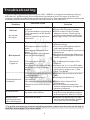
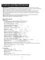
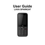
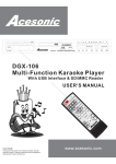
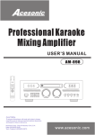
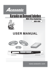
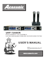
The Leader in Professional Equipment UHF-1208XR DUAL DIVERSITY 100 CHANNELS UHF RECHARGEABLE WIRELESS MICROPHONE SYSTEM USER’S MANUAL NOTE: To ensure this component will work safely and to its fullest potential, please read this user’s manual carefully before operation and keep for future reference. www.acesonic.com Warnings, Cautions and Others Mises en garde, precautions et indications diverses For Canada/Pour le Canada CAUTION CAUTION: TO PREVENT ELECTRIC SHOCK, MATCH WIDE BLADE OF PLUG TO WIDE SLOT,AND FULLY INSERT. ATTENTION: POUR EVITER LES CHOCS ELECTRIQUES, INTRODUIRE LA LAME LA PLUS LARGE DE LA FICHE DANS LA BORNE CORRESPONDANTE DE LA PRISE ET POUSSER JUSQUAU FOND. RISK OF ELECTRIC SHOCK DO NOT OPEN CAUTION: TO REDUCE THE RISK OF ELECTRIC SHOCK. DO NOT REMOVE COVER (OR BACK). NO USER SERVICEABLE PARTS INSIDE. REFER SERVICING TO QUALIFIED SERVICE PERSONNEL. The lightning flash with arrowhead symbol, within an equilateral triangle is intended to alert the user to the presence of uninsulated dangerous voltage within the product's enclosure that may be of sufficient magnitude to constitute a risk of electric shock to persons. The exclamation point within an equilateral triangle is intended to alert the user to the presence of important operating and maintenance (servicing) instructions in the literature accompanying the appliance. For Canada/Pour le Canada THIS DIGITAL APPARATUS DOES NOT EXCEED THE CLASS B LIMITS FOR RADIO NOISE " EMISSIONS FORM DIGITAL APPARATUS AS"SET OUT IN THE INTERFERENCE-CAUSING " EQUIPMENT STANDARD "ENTITLED DIGITAL APPARATUS, ICES-003 OF THE DEPARTMENT OF COMMUNICATIONS. CET APPAREIL NUMERIQUE RESPECTE LES LIMITES DE BRUITS RADIO ELECTRIQUES APPLICABLES AUX APPAREILS NUMERIQUES DE CLASSE B PRESCRITES DANS LA NORMESUR LE MATERIEL BROUILLEUR: APPAREILS NUMERIQUES , NMB-003 EDICTEE PAR LE MINISTRE DES COMMUNICATIONS. CAUTION To reduce the risk of electrical shocks, fire, etc: 1.Do not remove screws, screws, covers or cabinet. 2.Do not expose this appliance to rain or moisture. FCC INFORMATION (U.S.A.) 1.This equipment has been tested and found to comply with the limits for a Class B digital device, pursuant to part 15 of the FCC Rules. These limits are designed to provide reasonable protection against harmful interference in a residential installation. This equipment generates, uses and can radiate radio frequency energy and, if not installed and used in accordance with the instructions, may cause harmful interference to radio communications. However, there is no guarantee that interference will not occur in a particular installation. If this equipment does cause harmful interference to radio or television reception, which can be determined by turning the equipment off and on, the user is encouraged to try to correct the interference by one or more of the following measures: Reorient or relocate the receiving antenna. Increase the separation between the equipment and receiver. Connect the equipment into an outlet on a circuit different from that to which the receiver is connected. Consult the dealer or an experienced radio/TV technician for help. Caution Disconnect the electrical plug to shut off power completely. The POWER on the unit is not off from the electrical plug when the POWER button on the front panel is not pressed in. 2.IMPORTANT: When connecting this product to accessories and/or another product use only high quality shielded cables. Cable(s) supplied with this product MUST be used. Follow all installation instructions. Failure to follow instructions could void your FCC authorization to use product in the U. S. A. 2 Important Safety instructions 18. Overloading Do not overload wall outlets, extension cords, or integral convenience receptacles as this can result in a risk of fire or electric shock. 1. Read These Instructions. 2. Keep These Instructions. 3. Heed All Warnings. 19. Object and Liquid Entry Never push objects of any kind into this product through openings as they may touch dangerous voltage points or short-out parts that could result in a fire or electric shock. Never spill liquid of any kind on the product. 4. Follow All Instructions. 5. Do not use this product near water. 6. Clean only with dry cloth. 7. Do not block any ventilation openings. 20. Replacement Parts When replacement parts are required, be sure the service technician has used replacement parts specified by the manufacturer or have the same characteristics as the original part. Unauthorized substitutions may result in fire, electric shock, or other hazards. 8. Do not install near any heat sources such as radiators, heat register, stoves, or other apparatus (including amplifiers) that produce heat. 9. Do not defeat the safety purpose of the polarized or grounding-type plug. A polarized plug has two blades with one wider than the other. A grounding type plug has two blades and third grounding prong. The wide blade or the third prong are provided for your safety. If the provided plug does not fit into your outlet, consult an electrician for replacement of the obsolete outlet. 21. Safety Check Upon completion of any service or repairs to this product, ask the service technician to perform safety checks to determine that the product is in proper operating condition. 22.Wall or Ceiling Mounting The product should be mounted to a wall or ceiling only as recommended by the manufacturer. Any mounting of the product should follow the manufacturer instructions, and should use a mounting accessory recommended by the manufacturer. 10. Protect the power cord from being walked on or pinched particularly at plugs, convenience receptacles, and the point where they exit from the apparatus. 11. Only use attachments and accessories specified by the manufacturer. 23. Wet location marking Apparatus shall not be exposed to dripping or splashing and no objects filled with liquids, such as vases, shall be placed on the apparatus. 12. Use only with the cart, stand, tripod, bracket, or table specified by the manufacturer, or sold with the apparatus. When a cart is used, use caution when moving the cart. 13. Unplug this apparatus during lightning storms or unused for long period of time. Apparatus combination to avoid injury from tip-cover. 14. Refer all servicing to qualified service personnel. Servicing is required when the apparatus has been damaged in any way, such as power-supply cord or plug is damaged, liquid has been spilled or objects have fallen into the apparatus, the apparatus has been exposed to rain or moisture, does not operate normally, or has been dropped. 24. Outdoor Antenna Grounding If an outside antenna or cable system is connected to the product, be sure the antenna or cable system is grounded so as to provide some protection against voltage surges and built-up static charges. Article 810 of the National Electrical Code, ANSI/NFPA 70, provides information with regard to proper grounding of the mast and supporting structure, grounding of the lead-in wire to an antenna discharge unit, size of grounding conductors, location of antenna discharge unit, connection to grounding electrodes, and requirements for the grounding electrode. See figure below. 15. This product should be operated only from the type of power source indicated on the marking label. If you are not sure of the type of power supply to your home, consult your product dealer or local power company. For products intended to operate from battery power, or other sources, refer to the operating instructions. 16. Protective Attachment Plug The product is equipped with an attachment plug having overload protection. This is a safety feature. See Instruction Manual for replacement or resetting of protective device. If replacement of the plug is required, be sure the service technician has used a replacement plug specified by the manufacturer that has the same overload protection as the original plug. 25. Servicing If your product is not operating correctly or exhibits a marked change in performance and you are unable to restore normal operation by following the detailed procedure in its operating instructions, do not attempt to service it yourself as operating instructions, do not attempt to service it yourself as opening or removing covers may expose you to dangerous voltage or other hazards. Refer all servicing to qualified service personal. 17. Power Lines An outside antenna system should not be located in the vicinity of overhead power lines or other electric light or power circuits, or where it can fall into such power lines or circuits. When installing an outside antenna system, extreme care should be taken to keep from touching such power lines or circuits as contact with them might be fatal. 3 Acesonic UHF-1208XR Thank you for purchasing Acesonic's UHF-1208XR. Acesonic takes pride in providing our custmers with only the most advanced and highest quality karaoke products on the market. Please read trough this USER’S MANUAL before operation to ensure proper usage, and keep for future Table of Contents Warnings and Caution....................................................................................2 Safety Instructions........................................................................................3 Table of Contents...........................................................................................4 Included Accessories.................................................................................... 4 Receiver/Display panel Descriptions............................................................. 5 Microphone Descriptions/Operation/Channel Switching...............................6 Installation & IR SYNCing(channel switching)/Battery Recharging...............7 Troubleshooting............................................................................................8 Features & Specifications..............................................................................9 Manufacturer Information............................................................................10 Parts checklist Before installing your wireless microphone, Here are a few things you should do/know: l Handheld microphone(2) 3 ft. male to male ¼" cable (1) l l Mounting brackets(1 Set) l Antenna(2) l AC power adapter(2) l User manual / warranty card(1) l UHF-1208X receiver (1) l Microphone Battery Recharging Dock(1) l Rechargeable Battery(4) *Be sure to keep original packaging in case of re-shipping is needed. Matters Need Attention 1)Check to see whatever the local voltage accord with operating receiver voltage(Wrong selection may lead to burn out of receiver) 2)Do not dismantle the machine on your own. For internal repair, please contact the local distributor or accepted service center. Please see page 10 for more detail. 3)When the machine will not be used for a long time, please disconnect the power plug from receiver. 4)Do not recharge your batteries until the batteries are low. Cleaning l Please make sure the power is disconnected before cleaning or repairing the machine. l The machine can be cleaned by using a soft cloth with water. Dry the machine with a dry cloth and let it air dry for 15 minutes. l Please do not use volatile gasoline, diluents or other chemicals to cleaned the machine 4 Receiver Descriptions 4 2 1 3 1) Power switch -Turns the UHF-1208X on and off. 2) RF & AF indicator- RF indicator shows radio frequence signal level which receiver is getting. AF indicator shows the audio frequence signal level from the microphone. If receiver catches microphone’s signal, the RF & AF indicator will show the signal level 3)Channel A display panel - Display all information like the frequency channel of the microphones, channel scanning information, or channel lock/unlock 4)Channel A volume control knob - Adjust the volume on the microphone A. 5)Channel A operating buttons: IR SYNC/UP button: press twice in the roll to start IR Syncing process. turn on the microphone and press the microphone button again shortly to complete the channel matching between receiver and microphone. Or you can use this button as UP button in MENU mode. STOP/MENU button: use this button to stop channel scanning, the receiver will automatically select the best/cleanest channel from all channels scanned. You can also use this button to enter MENU mode: In MENU mode, there are four categories: 1. Frequency: use UP or Down button to manually select receiver channel. 2.Scan: use to start auto channel scanning process. usually will need about 90 seconds to complete the process. after scanning, receiver will pick the best channel. 3.IR: to start IR sync (channel matching) process between receiver and microphone. 4.LOCK: to lock or unlock the buttons on the receiver. keep the distance between microphone and receiver IR launcher with-in 1 meter, then press the button on the microphone . If IR sync successes, the CH in the LCD screen will stop flashing and you can see the RF signal bar on the LCD screen. 5)IR launcher - submit matching signal to the receiver on the button of the microphone in order to make microphone match the same channel with this receiver. Rear panel descriptions 9 8 7 6 6) 12V AC power connection- Main power jack to power the system. Conect to wall outlet. 7) Channel A & B Mix unbalance audio output jack - Output jack that are used for connecting to amplifier, mixer or karaoke player. Will send both Channel A & B sound. 8)Channel A balance audio output jack - Output jack that are used for connecting to amplifier, mixer or karaoke player. Will only send Channel A sound. 9)Channel B balance audio output jack - Output jack that are used for connecting to amplifier, mixer or karaoke player. Will only send Channel B sound. 5 1208XR Microphone Descriptions 1)Cartridge module- This is where you would sing into. 2)Microphone body- The main frame of the microphone. 3)Operating indicator and 4)Switch buttonHold the switch button for 1 second to turn on the power. Light will turns green means microphone is now in working condition. When it lights up green, then press switch button shortly, the light will turn yellow, means microphone is in mute mode, no sound will comes out from microphone. to go back to working mode, press the switch button shortly again, the light will turn green. When IR syncing, microphone needs to stay power on, but can be either working or mute mode. After switching channel on the receiver and start IR syncing. Then put the button part of the microphone to face the IR launcher on the receiver, the distance need to be under 1 meter. Press the microphone switch button shortly to confirm the IR syncing. If IR sync successes, the CH in the LCD screen will stop flashing and you can see the RF signal bar on the LCD screen. 5)Battery cover 6)IR receiver & charging unit - This is the base of the microphone. The bottom part has a IR receiving unit inside which receive the IR signal from receives to complete the IR matching for microphone and receiver. Microphone Operation & Channel switching: 1) Install batteries into microphone handheld. 2)Turn on microphone by pushing the switch towards, the indicator should turn green. 3)To mute the microphone, push the switch button shortly, the light will turns yellow. 4)To turn off the microphone, push the switch button for about 1~2 seconds then release it, the indicator light will turns off. 5)If you are not going to use the microphone for a long period of time, turn off the microphone and pull out the batteries to avoid deterioration and damage toward the components. 6 ) When IR syncing, microphone needs to stay power on, but can be either working or mute mode. After switching channel and start IR syncing on the receiver . Put the button part of the microphone to face the IR launcher on the receiver, the distance need to be under 1 meter. Press the microphone switch button shortly to confirm the IR syncing. if IR syncing got confirmed, the channel information on the LCD of receiver will stop flashing and you can see the RF signal bar on the LCD screen. * For quick microphone channel matching process, please see the note on the top of receiver, or see page 7 for more detail. 6 Installation Power amplifier AM-828 MIXING AMPLIFIER POWER ON OFF A UX D VD U SB BGM KEY +6 +5 +4 +3 +2 +1 L 0 +1 +2 +3 db +4 +5 +6 R Mixer AUX INPUT VIDEO L DVD R AUX USB BGM AUTO INPUT SELECTOR MUTE L STEREO R BBE VO C A L PAR T N E R Player MUSIC VOL MIC MASTER VOL V O C AL CANCE L SOUND MODE KEY C ONTROL 1 2 3 4 5 6 7 8 9 0 Music Volume Mic Volume KM-110 Karaoke Mixer Mic 1 Mic 2 Mic 2 TREBLE BASS MUSIC DELAY ECHO REPEAT TREBLE BASS MIC 1 VOL MIC 2 VOL MIC 3 VOL HEADPHONE MIC 1 MIC 2 On MIC 3 Mic 3 Mic Treble Mic Bass 3D Sound 10 10 -10 +10 -10 Off +10 CD+G DOLBY D I G I T A L Mic Echo Mic 3 10 BALANCE MPEG-4 Playback Mic 1 Power POWER 10 On SD/MMC USB MINI SD ON 10 OFF Off DGX-106 DVD MPEG-4 KARAOKE PLAYER MIC1 MIC2 VOL1 VOL2 EC HO BA SS TREBLE MIC Mic. Input Mic. Input ¼" to ¼" cable Mic. Input Power Outlet AC Power adapter cable 1) Connect the AC POWER ADAPTER to the UHF-1208X receiver’s AC INPUT 110V, then plug the other end of AC POWER ADAPTER into the WALL OUTLET. 2)Connect one end of a ¼" TO ¼" CABLE to the U HF-1208X receiver’s UNBALANCE AUDIO OUTPUT(MIX) and the other end to a karaoke mixer, karaoke player or karaoke power amplifier ¼" microphone input. If you are using the BALANCE AUDIO OUTPUT, use a XLR to XLR cable or XLR to ¼" cable . 3)Unscrew the microphones handle cover(counter-clockwise) to check to see if there are batteries. If not, install batteries into the microphones with the negative and positive end of the battery correspond the negative and positive end of the microphone. Screw the microphone handle back on(clockwise). Quick IR SYNC (Channel Matching between receiver and microphone) 1) O n the receiver, press MANUAL SCAN button twice in the roll to start auto channel scanning process. The whole auto scanning process will be finished around 90 seconds. However, you can stop auto scanning anytime by pressing STOP button. Receiver will select the best/cleanest channel from the channels just went thought. 2) Power on the microphone handheld and use its button part to face the IR SYNC laugher on the receiver front panel to prepare the next step(IR syncing). 3) On the receiver, press IR SYNC button twice in the roll to start IR syncing process. When the receiver LCD screen shows IRING, press microphone button and release shortly. If IR SYNC success, the LCD screen will show IR OK. 4) Please remain the 1st microphone power on before starting the 2nd microphone’s auto channel scanning. otherwise receives might get the same(cleanest) channel for both #1 and #2 microphone while auto channel scanning. How to charge your rechargeable batteries 1)Please use rechargeable dock and wireless microphone handheld which comes with the package to charge the rechargeable batteries. 2)Please do not recharge the batteries until the batteries is low, while microphone light indicated with the flashing red light. 3)When using rechargeable dock charging batteries, the charging indicate light on the charging dock will turns red while batteries charging. when rechargeable batteries full , the light will turns off. 4.Charging the batteries before it is low will cause the batteries usage life span to shorten. *Batteries recharging time = 1.5 hours *Do not charge the batteries if you are not using rechargeable batteries. 7 Troubleshooting If you are having problems operating the UHF-1208XR, or suspect something is wrong with the unit, please check the troubleshoot list below to see if the issue is a result of incorrect operation rather than equipment malfunction. If you are still unable to resolve the problem, please contact our Acesonic service center at 626-820-0670. Problem Reciver No sound; No lights Microphone No sound; Lights on Distorted sound; feedback Outside noise 1Batteries still running low even after recharging it Possible cause l Power button is on the OFF position l AC power adater is not plug in l Poor connection of AC power adapter l How to switch from different channels? Solution l Turn on the power button l Plug in the AC power adapter l Check to see if the AC power adapter is loose. Check on the receiver end and wall outlet end l See page 6 and 7 for more detail l The transmitter is out of range l Operate the machine in the effective range l Microphone switch is off or l Turn on the microphone switch mute (indicated green light) l Microphone volume is turn l Turn on the microphone volume on down the receiver l Batteries in the microphone l Reinstall the batteries. Make sure are not install properly the positive and negative end are install correctly l The antenna is not fully functional. l Receiver is not connect to an amplifier, mixer or karaoke player l Try to change the angel of the antenna l Connect the ¼ to ¼ or XLR cable from the receiver to a microphone input (mixer, player, etc.). See Page 7 for detail l Separate the microphone further away l Recharge the batteries l The two microphones are too close together l Batteries running low in microphone l Microphone volume is too high l Reduce the volume of the microphone l Distortion from other electric l Move the reliever away from wave electric equipment or change the frequency channel Change the channel on receiver l Radio frequency got occupied l and IR syncing between receiver by other radio device. and microphone. See P.6~7 also l Replace the batteries.(You can l Batteries are bad use Normal AA batteries as well. They just can’t be recharge) * For quick microphone channel matching process, please see the note on the top of receiver, or see page 7 for more detail 8 Features and Specifications Features: l Professional Heavy duty rack mountable receiver, UHF diversity wireless system l Almost zero noise output when on standby, high signal/noise ratio, super low distortion. l 1000 switchable channels, with auto channel selection function. l Dual channel information LCD display and individual microphone volume control. l Perfect operative status signals, fluorescence display, with digital microphone. l Long practical distance. Over 100 m in ideal circumstance ,25 m radius in complex circumstances. l Easy IR syncing for quick channel matching between receiver and microphone. l Front antennas provides clear radio frequence reception. l Microphone batteries rechargeable function Specifications: Receiver Carrier Wave Frequency Range: UHF 668~692 MHz Oscillation Mode: Phase-locked Loop controlled Carrier Wave Stability: 10PPM Switching bandwidth: 24MHz Frequency Space:≥250KHz Sensitivity: -105dB @ sinad=12 dB S/N Ratio: >105dB T.H.D.: <0.5% @ 1KHz Image rejection: 85 dB typical Spurious rejection: 75 dB typical Frequency Responses: 40Hz~18KHz Working distance:200 feet (open area) Squelch Control: dual-squelch circuit AF Output Impedance:2.2KΩ Max. Output Level: Balance : 0—400mv , Unbalance : 0—200mv Display:2 x LCD Power Supply: External DC Power Supply, 0.5A, 12~18V DC Output Connector: 2x XLR Balanced Socket. 1x Unbalance TRs⊙6.35mm Socket Dimensions (m/m): 420(L)×45(H)×200(D) Weights (Kg): 2.5 Transmitter Transmitter power: 30mW Spurious emission: <40dB(with carrier) Display:LED Battery voltage: 1.5v×2 Battery life: Vary by using behavior and batteries capacity. 9 Manufacturer Information Contact Info: 1 Year Manufacturer Warranty Lifetime Tech. Support Design in U.S.A Tech. Support: (626)820-0670 Address: 161 S. 8th Avenue City of Industry, CA 91746-3208, USA Website: www.acesonic.com Note: 10