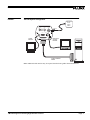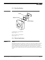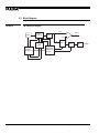
1
TM-1300
Progressive Scan High Resolution Camera
Operations Manual
69-0048
Rev. A
Notice
The material contained in this manual consists of information that is proprietary to PULNiX America, Inc., and may only
be used by the purchasers of the product. PULNiX America, Inc. makes no warranty for the use of its product and assumes
no responsibility for any errors which may appear or for damages resulting from the use of the information contained
herein. PULNiX America, Inc. reserves the right to make changes without notice.
Warranty
All of our solid state cameras have a full three year warranty. If any such product proves defective during this warranty
period, PULNiX America, Inc. will repair the defective product without charge for parts and labor or will provide a
replacement in exchange for the defective product. This warranty shall not apply to any damage, defect or failure caused
by improper use or inadequate maintenance and use.
Certifications
UL
CE
FCC
This equipment has been tested and found to comply with the limits for a Class A digital device, pursuant to Part 15 of the
FCC Rules. These limits are designed to provide reasonable protection against harmful interference when the equipment
is operated in a commercial environment. This equipment generates, uses and can radiate radio frequency energy and, if
not installed and used in accordance with the instruction manual, may cause harmful interference to radio communications. Operation of this equipment in a residential area is likely to cause harmful interference in which case the user will
be required to correct the interference at his own expense.
WARNING
Changes or modifications to this unit not expressly approved by the party responsible
for FCC compliance could void the user’s authority to operate the equipment.
TM-1300 Operation Manual
Printing: June 1998
PULNiX America, Inc.
1330 Orleans Drive
Sunnyvale, CA 94089
Tel: (408) 747-0300
Tel: (800) 445-5444
Fax: (408) 747-0880
Table of Contents
1 INTRODUCTION
1.1
1.2
1.3
1.4
Product Description .......................................................................... 1
Features ........................................................................................... 1
Functional Options ........................................................................... 2
Applications ...................................................................................... 2
2 INSTALLATION
2.1
2.2
3.2
..................................................................... 4
Getting Started ................................................................................. 4
2.1.1 Unpacking Instructions ........................................................ 4
2.1.2 Components List ................................................................. 4
2.1.3 Accessories ......................................................................... 4
Camera Setup .................................................................................. 5
2.2.1 Connector Pin Configurations ............................................. 5
2.2.2 Rear Panel .......................................................................... 7
2.2.3 Power Supply and Power Cable Setup ................................ 7
2.2.4 Attaching the Video Output ................................................. 8
2.2.5 Attaching the Camera Lens ................................................. 9
2.2.6 Back Focusing the Lens ...................................................... 9
2.2.7 Auto Iris Lens Setup ............................................................ 9
2.2.8 Monitor Display Mode .......................................................... 9
2.2.9 Connectors and Cables ....................................................... 10
3 OPERATION
3.1
.................................................................... 1
.......................................................................... 11
Modes of Operation .......................................................................... 11
3.1.1 Shutter Control Switch ........................................................ 11
3.1.2 Asynchronous Shutter ......................................................... 13
3.1.3 Frame Memory (Memory Output Mode) .............................. 14
3.1.4 Video Output ....................................................................... 15
3.1.5 Mode Control Functions ...................................................... 16
3.1.6 Digital Output Pulses ........................................................... 19
3.1.7 TM-1300 RS-232C Control ................................................. 21
Board Layout and Adjustment .......................................................... 26
3.2.1 Signal Board (Top Side) ...................................................... 26
3.2.2 Power Board (Bottom Board, Top Side) .............................. 27
3.2.3 Power Board (Bottom Board, Top Side) .............................. 27
3.2.4 Memory Board (Middle Board, Bottom Side) ...................... 27
4 TROUBLESHOOTING
4.1
4.2
........................................................... 29
Problems and Solutions ................................................................... 29
4.1.1 Symptom: No Video ............................................................. 29
4.1.2 Symptom: Dark Video .......................................................... 29
4.1.3 Symptom: Non-synchronized Video .................................... 29
4.1.4 Symptom: RS-232 Non-communication .............................. 29
Information and Support Resources ................................................ 30
i
Table of Contents
5 APPENDIX
5.1
5.2
5.3
5.4
.............................................................................31
Specifications ................................................................................... 31
5.1.1 Product Specifications ......................................................... 31
5.1.2 Physical Dimensions ............................................................ 32
5.1.3 Glass Specifications ............................................................ 33
5.1.4 C-Mount Specifications ........................................................ 33
5.1.5 Front End Detail ................................................................... 34
Spectral Response ........................................................................... 35
Block Diagram .................................................................................. 36
Digital Cable Assembly ..................................................................... 37
5.4.1 TM-1300 31-Pin Connector ................................................. 37
5.4.2 37-Pin D-Sub Connector Pin Configuration ......................... 38
ii
List of Figures
FIGURE 1.
TM-1300 System Configuration
................................................. 3
FIGURE 2.
TM-1300 Rear Panel
FIGURE 3.
12P-02 Interface Cable (optional)
FIGURE 4.
Internal Reset Mode
FIGURE 5.
VINIT (Vertical Initialization) Trigger Specification
FIGURE 6.
Asynchronous Shutter
FIGURE 7.
Integrated Image Capture Timing
FIGURE 8.
A/D Dynamic Range
FIGURE 9.
Normal Mode vs. Fast Dump Mode
FIGURE 10.
Line Data Valid
FIGURE 11.
Frame Data Valid
FIGURE 12.
Pixel Clock
FIGURE 13.
TM-1300 Camera Control Commands
FIGURE 14.
Signal Board (top side)
FIGURE 15.
Power Board
FIGURE 16.
Memory Board (bottom)
FIGURE 17.
Physical Dimensions
FIGURE 18.
Camera Front End - Glass Specifications
FIGURE 19.
C-Mount
FIGURE 20.
Combination With “CS-Mount” Camera
FIGURE 21.
TM-1300 Imager Location
FIGURE 22.
Front End Assembly
................................................................... 35
FIGURE 23.
Spectral Response
..................................................................... 35
FIGURE 24.
TM-1300 Block Diagram
.................................................................. 7
.............................................. 8
................................................................... 13
...................... 14
................................................................ 14
............................................... 16
................................................................... 17
............................................ 19
........................................................................... 20
........................................................................ 20
.................................................................................. 21
....................................... 25
............................................................... 26
............................................................................... 27
............................................................. 28
.................................................................. 32
.................................. 33
..................................................................................... 33
iii
...................................... 34
.......................................................... 34
............................................................. 36
June 11, 1998
TM-1300 Progressive Scanning
High Resolution Camera
Operations Manual
1
INTRODUCTION
1.1 Product Description
Compact and lightweight, the TM-1300 is a state-of-the-art CCD camera with a 2/3 inch 1.3K x 1K
progressive scan interline transfer CCD imager.
1.2 Features
•
1.3K x 1K progressive scan interline transfer CCD
The advantages of this CCD are:
•
High resolution (1300 x 1030 active pixels) for very high resolution and image quality.
Square pixels (6.7 x 6.7 µm for precise dimensional measurement).
High speed electronic shutter capability results in high dynamic resolution of moving objects.
Progressive scanning eliminates interlace deterioration of image.
High sensitivity and low noise at fast scanning.
Asynchronous reset
The TM-1300 can be reset with an external reset pulse (VINIT). This feature is especially
important for capturing moving objects at a precise location in the field of view, for applications
such as a conveyer belt, fast event observation, and still picture capturing.
•
Async image capturing
The TM-1300 captures an image using async reset and provides continuous video output of the
same image.This makes it simpler for an ordinary frame grabber to capture the async reset images.
Page 1
INTRODUCTION
•
Frame memory and digital output
The TM-1300 has a built-in frame grabber and a frame memory. There are two modes of digital
output available:
Direct output mode: 10-bit output without going through an internal frame buffer (direct from the
A/D converter via RS-422).
Memory mode: 8-bit output with the internal frame buffer, to capture the asynchronous image
inside of the camera. The 10-bit A/D converter provides 1024 gray levels with maximized signal-tonoise ratio. The output can be real time digital output or captured image (frozen picture).
•
Pixel clock rate
The standard pixel clock frequency is 20 MHz.
•
Integration
The TM-1300 is capable of capturing high resolution integration images. Integration can last from
1/12 sec. to a few seconds.
•
Analog output (SVGA, BNC)
Since the TM-1300 is non-TV format, a frame grabber and computer, special monitor or SVGA
monitor must be used to display the video output.
The TM-1300 outputs analog signals from the SVGA and BNC connectors. The analog signal is
processed in the camera for scan conversion in order to output high frame rate video (SVGA). The
analog outputs are not recommended to be used for signal processing. While the digital is 10-bit
non-interlace, the analog is 8-bit or 8-bit x 3 (SVGA) non-interlace output.
•
A/D reference voltage and dynamic range control
The 10-bit A/D converter’s reference voltage can be controlled by back panel switches or RS-232C.
The high reference and low reference variation provides A/D or signal processing dynamic range to
maximize CCD characteristics.
•
Remote RS-232C control
The back panel mode switch functions, gain control, shutter speed, A/D reference functions and the
data preset are all controllable via RS-232C communication.
1.3 Functional Options
•
Optical Filter Removal (OP3-2)
•
Glassless CCD Imager (OP21)
•
Internal IR Filter (OP3-1)
1.4 Applications
The versatile TM-1300 meets the needs of a broad range of applications, including high resolution
image capturing, machine vision, computer graphics, gauging, avionics, microscopy, medical imaging,
character and fine pattern recognition, document reading and high end surveillance.
Page 2
TM-1300 Progressive Scanning High Resolution Camera
INTRODUCTION
FIGURE 1.
TM-1300 System Configuration
Ext. Sync
Power
Trigger
Others
78
B C DE
78 9 A
DWN
F0 1 2
POWER
12P-02
6
6
MODE
345
234
SHUTTER
UP
9 01
5
VIDEO
SVGA
DIGITAL
SVGA
Monitor
Multi Sync
Analog
Monitor
Frame Grabber
Board
Note: Additional cable interface may be required from the frame grabber board manufacturer.
TM-1300 Progressive Scanning High Resolution Camera
Page 3
INSTALLATION
2
INSTALLATION
The following instructions are provided to help you to set up your video camera system quickly and
easily. It is suggested that you read through these instructions prior to unpacking and setting up your
camera system.
2.1 Getting Started
2.1.1 Unpacking Instructions
It is recommended that the original packing cartons for the cameras and lenses be saved in case there is
a need to return or exchange an item.
It is also recommended that any equipment being sent to another location for field installation be bench
tested to assure that everything is fully operational as a system.
2.1.2 Components List
Please begin by checking your order against the Components List (below) to assure that you have
received everything as ordered, and that nothing has been overlooked in the packing materials. If any
item is missing, please contact your PULNiX representative immediately.
•
TM-1300 camera
•
30DG-02-40 digital cable
•
PD-12P power supply (650mA)
•
TM-1300 Data Sheet
•
TM-1300 Operations Manual
2.1.3 Accessories
Following is a list of additional accessories or equipment that may be recommended or required for your
particular application. Please check with your PULNiX representative prior to the installation of your
video system to determine what you might need.
Page 4
•
RS-232 controller cable
•
RS-232 controller software
TM-1300 Progressive Scanning High Resolution Camera
INSTALLATION
2.2 Camera Setup
2.2.1 Connector Pin Configurations
2.2.1 (a)
12-Pin Connector
1
The TM-1300 has a 12-pin connector for power input. Pin #1 is Ground and Pin
#2 is +12V DC. The other pins handle a number of other input and output
functions as detailed below.
Pin
Description
Pin
Description
1
GND
7
Strobe out+
2
+12V DC
8
Strobe out-
3
GND
9
RS-232 TXD
4
Video Out
10
RS-232 RXD
5
GND
11
Integration
6
VINIT In
12
N/C
Note:
2
3
9
11
4
8
10
7
12
5
6
Strobe output is differential but can be used as positive going TTL or negative going TTL.
2.2.1 (b)
SVGA Output Connector (15-pin Dsub miniature connector)
2.2.1 (c)
Digital Output Connector
An EIA-422 digital output is available from the 31-pin high-rel, micro-miniature connector (Airborn
MP221-031-243-2200). The mating connector can be firmly secured to the receptacle for vibration and
shock environments. A common D-sub connector was not used to prevent any vibration problems.
1
16
31
17
Pin
Description
I/O
Pin
Description
I/O
1
CLK+
Out
17
CLK-
Out
2
LDV+
Out
18
LDV-
Out
3
FDV+
Out
19
FDV-
Out
4
GND
20
VINIT
In
5
N/C
21
INTEG
In
TM-1300 Progressive Scanning High Resolution Camera
Page 5
INSTALLATION
Pin
Description
I/O
Pin
Description
I/O
6
D0+
Out
22
D0-
Out
7
D1+
Out
23
D1-
Out
8
D2+
Out
24
D2-
Out
9
D3+
Out
25
D3-
Out
10
D4+
Out
26
D4-
Out
11
D5+
Out
27
D5-
Out
12
D6+
Out
28
D6-
Out
13
D7+
Out
29
D7-
Out
14
D8+
Out
30
D8-
Out
15
D9+
Out
31
D9-
Out
16
GND
Shield
2.2.1 (d)
Setting
O
1
2
Mode
Normal Mode
MGC gain control
Async / Manual shutter
3
5
Gain selection (9 dB)
Gain selection (12 dB)
Gain selection (18 dB)
Gain selection (22 dB)
Image output selection
6
7
8
A/D Vref top
A/D Vref bottom
Freeze (ENINT) enable
9
A
B-D
Factory default recall
User power up default
(default page at power up)
User page storage
E
F
Direct shutter
Fast dump
4
Page 6
Mode Control Switch
Up/Down (6 to 22 dB)
Up: Manual
Down: Async
Up to set
Down
Up
Down
Up: Direct digital mode
Digital: 10-bit without memory
12 frame/sec (20MHz)
Analog: SVGA/SXGA, 47 frame/sec.
Down: Memory mode
Digital: 8-bit through memory, 12frame/sec (20MHz)
Analog: 12 frame/sec, no-display mode
Up/Down
Up/Down
Up: Real time
Down: Freeze
Up/Down: Recall factory default
Up: Load user default data
Down: Save data (latest data)
Up: Load
Down: Save
Up/Down (1/39,000 to 1/12 sec., 1H increment)
Up: Normal mode
Down: Fast dump mode
TM-1300 Progressive Scanning High Resolution Camera
INSTALLATION
2.2.2 Rear Panel
TM-1300 Rear Panel
B C DE
78
6
POWER
F0 1 2
78 9 A
DWN
MODE
345
234
SHUTTER
UP
9 01
6
FIGURE 2.
5
VIDEO
SVGA
DIGITAL
2.2.3 Power Supply and Power Cable Setup
2.2.3 (a)
Power Supplies
PULNiX recommends the following power supplies:
K25-12
110V AC/12V DC
2.1A power supply
P-15-12
220V AC/12V DC
2.1A power supply
K50-12
110V AC/12V DC
4.2A power supply
PD-12P
110V AC/12V DC
0.5A power supply
For users providing power through the 12-pin connector, the PD-12P power supply is available with the
12-pin mating connector already attached to the leads from the power supply. The PD-12 power supply
can be connected to the PULNiX power cable via a terminal strip or directly.
If wiring the PD-12 power supply directly, please note the following:
•
Twist the lead ends together and tin solder for strength and electrical continuity.
•
Use shrink tubing or a similar insulator to prevent exposed leads from touching.
•
The +12V lead is marked with a red stripe or white lettering; be sure not to reverse the leads.
•
Properly insulate all connections to prevent shorting.
2.2.3 (b)
Using PULNiX Power Cables
If you are using PULNiX power cables, such as the 12P-02, KC-10, etc., please refer to the pin-out
diagram. The color coded leads use Grey for Ground and Yellow for +12V DC.
TM-1300 Progressive Scanning High Resolution Camera
Page 7
INSTALLATION
FIGURE 3.
12P-02 Interface Cable (optional)
Flying
Leads
32mm
1
2,000mm± 10mm
(2 Meters)
1 PC-12P (Hirose Part #10A-10P-12S/PC12P)
Note:
Make sure that the unused leads are not touching and that there is no possibility that the
leads could short due to exposed wires.
2.2.3 (c)
Using the “K” Series Power Supplies
Attach the 110V line cord to the two terminals marked “AC”. Do not plug the cord into a 110V AC
socket until later in the procedure. Next, attach the Grey and Yellow leads of the power cable to the
Ground and 12V DC terminals respectively. Be sure to replace the plastic terminal guard on the power
supply at this time.
Note:
The “K” series power supplies are designed primarily for OEM users who will be
mounting the power supply inside a protective enclosure. For use in exposed situations,
the DC-12N and PD-12 are recommended.
2.2.3 (d)
Building Your Own Power Cables
If you are building your own power cables, consult the pin-out for the camera purchased and connect the
Ground and +12V power leads of the PC-12P power connector to Pin #1 and Pin #2, respectively
(power must be DC regulated, and of sufficient current to properly power the camera).
2.2.3 (e)
Attaching the Power Cable to the Connector
The 12-pin connector is keyed and will only fit in one orientation. Rotate the connector while applying
slight pressure until the keyways line up. Press the connector into place until firmly seated.
The power cord may now be plugged into the 100V AC socket, and the camera powered up.
2.2.4 Attaching the Video Output
Most users utilize the BNC connector for video output from the camera. Connect the output from the
camera to the input of your monitor, VCR or switching device. The input of the monitor should be
balanced for 75Ω termination. Standard RG-59 type coaxial cable should carry a full video signal for up
to 500 feet.
Page 8
TM-1300 Progressive Scanning High Resolution Camera
INSTALLATION
Users wishing to output the video and input the power and sync to a camera over a single cable can use
the PULNiX multi-conductor cables, such as the 12P-02, the KC-10, etc. The mini coaxial leads in
PULNiX multi-conductor cables are designed for short runs of no longer than 100 feet.
Note: Make sure that no extraneous wires are visible which could cause a short.
2.2.5 Attaching the Camera Lens
The TM-1300 camera accepts standard C-mount lenses. To attach the C-mount lens to the camera,
carefully engage the threads and rotate the lens clockwise until it firmly seats on the mounting ring. Do
not force the lens if it does not seat properly. Please note that some lenses with extremely long
flangebacks may exceed the mounting depth of the camera.
2.2.6 Back Focusing the Lens
To backfocus the TM-1300 camera, first attach a C-mount lens in the lens mount. Be sure that the lens is
properly mounted.
Set the lens focus to infinity (if the lens is a manual iris, set the iris to a high f-stop while still retaining a
well-illuminated image). Obtain the best focus possible at this setting, then loosen the two miniature hex
head set screws locking the focus ring in place. Now turn the entire lens and focus ring assembly back
and forth until the best image is obtained. Tighten the focus ring set screws. Your backfocus is now set.
2.2.7 Auto Iris Lens Setup
Auto-iris lenses with full video input can be used with the PULNiX TM-1300, although this camera
model does not come equipped with auto-iris input.
Note:
Make sure that the power is removed from the camera before connecting or disconnecting
the auto-iris lens. There is a small chance that damage could occur to the auto-iris lens by
plugging or unplugging it while the camera is powered up.
Power down the camera before installing the auto-iris lens. To install the auto-iris lens in a PULNiX
camera for which the auto-iris output is not supplied, wire the signal (video) on the lens into the
terminal 1 Vp to peak video output on the camera.
Point the camera at a light area and then quickly towards a darker area. If everything is working
properly, the iris should adjust for the light change.
2.2.8 Monitor Display Mode
For monitoring real time video, connect the SVGA output to a SVGA/SXGA computer monitor.
Since the standard frame rate is 12 Hz, it may not be easy to see detail on a monitor. Therefore, the TM1300 display mode provides scan conversion to 47 frame / sec rate. The analog output of the TM-1300
is more likely to be monitored by oscilloscope for the waveform analysis.
Analog signal monitoring does not take full advantage of the 10-bit signal processing capability. For 10bit output applications, use the digital output connector.
TM-1300 Progressive Scanning High Resolution Camera
Page 9
INSTALLATION
2.2.9 Connectors and Cables
The digital output connector is optional. Mating connector ordering information is as follows: PULNiX
Part No. 15-1623 (Airborn P/N: MP211-031-113-3400)
Straight Backshell (cover): PULNiX Part No.15-1625 (Airborn P/N: MM253-031-000-4300)
Cable assembly: Digital cable 30DG-02 (50-1301-01: 8-bit standard cable) or 30DG-02-40 (501224:10-bit cable). Special cable length or specific interface connector to a frame grabber board is
available upon request.
12-pin connector and cable: Standard cable is 12P-02 (2m, 8 conductor cable) for power and external
controls.
Page 10
TM-1300 Progressive Scanning High Resolution Camera
OPERATION
3
OPERATION
3.1 Modes of Operation
The TM-1300 is designed to accommodate a high resolution, on-line inspection reset mechanism with
full frame shutter. It accepts external horizontal sync (HD, TTL Levels) to lock the camera and VINIT
pulse for resetting the camera asynchronously. The shutter speed can be controlled by either RS-232
computer commands or internal shutter speed control with a 10-position dial switch on the back panel.
3.1.1 Shutter Control Switch
The TM-1300's asynchronous reset is flexible and takes external HD for phase locking. Applying a
VINIT pulse resets the camera's scanning and purging of the CCD. Do not supply VD if the
asynchronous reset is used. Instead, use HD to synchronize the camera to the external device.
When the async reset pulse (VINIT) is applied to High state (+5V)
0
with the dial switch set from1 to 9, the TM-1300 asynchronous
1
9
camera discharges the photo charges into the substrate drain
although the camera is still running on its sync timing and only
2
8
outputs captured video. When the negative going reset pulse is
3
7
applied, the camera will latch the falling edge to its next horizontal
4
6
drive and will immediately reset the vertical sync timing. The
5
maximum delay is 80.645µsec. (1H). Then the camera will start
Shutter Control Switch
integrating for the period of shutter control set by either computer
control or internal shutter control. Therefore the horizontal phase
will not be interrupted. The TM-1300 asynchronous camera will output one full frame of shuttered
video after reset.
TABLE 1.
Shutter Control Settings
Set
Manual Shutter Mode
Async Reset Mode
0
No Shutter (1/12)
1
1/50
1.5H
No Shutter (1/12)
1/39,000
2
1/100
2.5H
1/9,500
3
1/200
4.5H
1/5,500
4
1/400
8.5H
1/3,000
5
1/1,500
16.5H
1/1,500
6
1/3,000
32.5H
1/400
7
1/5,500
64.5H
1/200
8
1/10,000
64.5H
1/245
9
1/39,000
256.5H
1/50
TM-1300 Progressive Scanning High Resolution Camera
Page 11
OPERATION
Mode 0:
Mode 1-4:
Mode 5-9:
3.1.1 (a)
Normal Mode
Fast Mode
Slow Mode
Direct Shutter Control Mode
For Direct Shutter Control Mode, set the dial switch to “E”. When the up/down switch on the back plate
is used, the shutter increments or decrements by 1H from the current setting. By controlling through
RS-232C, the exact shutter speed can be programmed by feeding H number from 1H (actual shutter
speed is 0.5H) to 1000H. The back plate control status can be read with RS-232C control and saved into
customer pages (page A is the power up default; whenever power is switched on, page A status is
loaded). This shutter control can be applied to both manual and async shutter modes. As shown in
Table1 (above), the shutter speeds are inversed in manual and async modes.
At async shutter, the internal VINIT is generated at the leading edge (negative going edge) of the
external trigger pulse. Internal timing, including the video sync, is reset. The shutter speed is the same
as in manual shutter mode. One frame of video output will start at the completion of the exposure time
(approx. 243µsec.).
In Memory Output mode, the camera will output the same video from memory when VINIT is kept high
(5V) and update the image upon receiving the next trigger pulse. In Direct mode, with external pulse
input high, the video output is disabled as the camera keeps discharging the CCD image and provides
only black video. Therefore, if the direct digital output mode is chosen, the video output is only one
frame and then black video with sync.
3.1.1 (b)
Internal Reset Mode
For Internal Reset Mode, set the 10-position dial switch from “1” to “9”. When this mode is selected,
the camera resets with internal VINIT timing, which is latched to Hd, and video output is also
synchronized with internal VINIT timing without further delay. The shutter speed is controlled by the
dial switch.
Page 12
TM-1300 Progressive Scanning High Resolution Camera
OPERATION
FIGURE 4.
Internal Reset Mode
CCD
VD
External pulse
min. 2H
Hd
Internal Vinit
X
Shutter Speed
Transfer Gate
Pulse
Exposure Time
Purge pulse
(discharge)
3.1.2 Asynchronous Shutter
For Async Shutter mode, select mode control switch #2 and press the up/down switch down. When the
negative going reset pulse VINIT is applied to pin 6 of the 12-pin connector, the camera will latch the
falling edge to its next horizontal drive and immediately reset the vertical sync timing. Therefore, the
horizontal pulse phase will not be interrupted.
The TM-1300 asynchronous camera outputs a full frame of shuttered video in progressive scanning
format from a frame buffer. The frame buffer is updated with each new image captured upon receiving
the next negative reset pulse. Since the internal frame buffer is designed to capture asynchronously
triggered images and output them as continuous video, an ordinary frame grabber can be used with the
TM-1300 (some frame grabber boards cannot accept disrupted sync).
The scan converted analog output is continuous sync without interruption at the trigger point. Therefore,
a computer monitor can display steady images without losing sync or jumping images.
Note:
All trigger input signals should have a pulse width of 160µsmin. (2H) 80ms 1000H max.
for the camera to function properly.
TM-1300 Progressive Scanning High Resolution Camera
Page 13
OPERATION
FIGURE 5.
VINIT (Vertical Initialization) Trigger Specification
+5V
TTL
Level
t
Min
Max
24H
1000H
0V
t
FIGURE 6.
Asynchronous Shutter
ASYNC RESET
VINIT
VD
SG (TRANSFER GATE)
DISCHARGE PULSE
PROGRESSIVE OUTPUT
DIGITAL
VIDEO
ANALOG
VIDEO
OLD VIDEO
IN MEMORY
OLD VIDEO
IN MEMORY
SHUTTER
VIDEO
SHUTTER
VIDEO
SAME VIDEO FROM FRAME MEMORY (MEMORY MODE)
NO IMAGE (DIRECT OUTPUT MODE)
SAME VIDEO FROM
FRAME MEMORY
3.1.3 Frame Memory (Memory Output Mode)
The TM-1300 has a built-in frame memory which outputs progressive scanning images at a 12 Hz rate
(12 frames per sec). This feature provides the following advantages:
1.
2.
3.
Asynchronously captured images are output as standard continuous video signals so that a monitor
or frame grabber can display or process without a special asynchronous video grabber.
Integration video is continuously output until the next capture. Normally, a camera cannot output
the video signal during the integration, and the periodic integration causes a blinking video signal.
The TM-1300 memory keeps the stored image until the next image is completed so that there is no
blank interval during integration.
Digital format of the video output can be used as a direct interface with the computer. The format is
progressive.
3.1.3 (a)
1.
Activating Frame Memory
Asynchronous reset mode
Select switch #2 of the back panel for async.When External VINIT is high (5V), the TM-1300
expects the async pulse input. It resets at the negative going pulse edge and captures the frame
regardless of the shutter speed. The video output is kept disabled as the CCD is discharged
continuously during VINIT high. When the first VINIT pulse comes in, it resets the timing and
Page 14
TM-1300 Progressive Scanning High Resolution Camera
OPERATION
2.
captures the image (Fig. 5). The captured image is kept until the next pulse is applied for the next
image. If the switch is at normal mode (manual shutter mode), the video output is real time with
manual shutter.
Integration
Activate EN INT (Enable Integration) of mode selection #8 by pushing down the switch then input
INTEG control (#11 of 12-pin connector or #21 of 31-pin connector) as active low (TTL). When it
is low, the TM-1300 keeps integrating and, upon the rising edge of the INTEG control pulse, it
captures the frame and keeps it until next end of integration. When EN INT is high (open), video
output is in real time without freezing and one frame of the integrated image appears upon ending
of INTEG control pulse (during INTEG control low, it keeps the previous image but when INTEG
is high it only holds one frame). FDV (Field) Data Valid) is disabled during the integration and the
vertical pulse starts when the image is output.
3.1.3 (b)
Progressive Scanning
The TM-1300 uses a state-of-the-art CCD called a “Progressive scanning interline transfer CCD” which
scans all lines sequentially from top to bottom at one frame rate (12 Hz). Like a non-interlace computer
screen, it generates a stable crisp image without alternating lines and provides full vertical TV
resolution of 1000 lines (a monitor display may not be able to show 1000 lines due to monitor resolution
and interlace scanning of the analog output). The interline transfer architecture is also important to
generate simultaneous shuttering. This is different from full frame transfer architecture which requires a
mechanical shutter or strobe light in order to freeze the object motion.
The TM-1300 outputs the progressive scanned image with an electronic shutter in two different formats:
1.
Progressive scanning digital output
2.
The CCD signal goes through A/D converters. The frame memory is capable of capturing async and
integration video without having special frame grabbers. 10-bit digital output is available from 31pin connector with EIA-422 format (20 MHz clock rate).
Non-interlace scan analog output
The TM-1300 outputs non-interlace video for SVGA monitor display. The digital output of 31-pin
connector is also at 12 Hz with a 20 MHz pixel clock (progressive scan).
3.1.4 Video Output
3.1.4 (a)
Async Reset Image Capture
With built-in memory, an image can be captured when VINIT pulse is applied. The captured image will
be continuously scanned out until the next VINIT pulse occurs. (Ref. Figure 3, pg. 11).
3.1.4 (b)
Built-in Memory for Integration Image Capture
With the Freeze Enable with mode #8 (push down), set the integration control (pin #11) to low for
integration. Integrated video can be captured once integration control goes back to high. Upon rising
edge of integration, the image is transfered (SG) 9H later.
TM-1300 Progressive Scanning High Resolution Camera
Page 15
OPERATION
FIGURE 7.
Integrated Image Capture Timing
INTEG
VD
SG (TRANSFER GATE)
PROGRESSIVE OUTPUT
DIGITAL
VIDEO
OLD VIDEO
IN MEMORY
ANALOG
VIDEO
3.1.4 (c)
SHUTTER
VIDEO
OLD VIDEO
IN MEMORY
SAME VIDEO FROM FRAME MEMORY (MEMORY MODE)
NO IMAGE (DIRECT OUTPUT MODE)
SHUTTER
VIDEO
SAME VIDEO FROM
FRAME MEMORY
Continuous Sync Output
When async reset is applied, video sync is also reset asynchronously. This phenomenon causes video
picture rolling or bouncing on the monitor. With this feature, a continuous output (no more bouncing or
rolling pictures) will be achieved at async reset.
3.1.5 Mode Control Functions
3.1.5 (a)
0. Normal Mode
The camera outputs real time normal video signal without electronic shutter or asynchronous functions.
The shutter speed is 1/12 sec.
3.1.5 (b)
1. MGC Gain Control
CDS amplifier gain can be controlled by the up/down switch. The minimum gain is 6dB and the
maximum gain is 24dB (factory set is 18 dB at power on).
3.1.5 (c)
2. Async / Manual Shutter Selection
The electronic shutter mode is selected by up (manual) and down (async) switch. When it is in manual
mode, the shutter speed is programmed by the shutter speed switch. When the async shutter is selected,
the shutter timing works with VINIT (async reset pulse). If VINIT is kept high, it keeps discharging the
CCD. When negative going pulse comes in, it resets the timing and captures a image, holding it until the
next pulse comes. The async shutter speed is also selected by the shutter selection switch but exposure
times are inverted from manual shutter times.
3.1.5 (d)
3. and 4. Gain Selection
Fixed specific gain is recalled by selecting 3 or 4 and pressing up/down switch up or down.
3 - up9 dB
3 - down12 dB
Page 16
TM-1300 Progressive Scanning High Resolution Camera
OPERATION
4 - up16 dB
4 - down22 dB
3.1.5 (e)
5. Image Output Format Selection
The TM-1300 has three output connectors. The digital output is 10-bit or 8-bit from 31-pin connector
and the analog outputs are SVGA format (DB-15 connector) and composite video (BNC connector)
with sync.
When Image Selection (mode #5) is selected by pushing the switch up, the Direct Digital Output mode
is selected. This bypasses the memory buffer (cannot grab and freeze video images), and 10-bit 12
frame/sec digital output is generated. The analog output is scan-converted to SVGA speed
(47 frame/sec).
When the switch is down, Memory mode is selected. The digital signal goes through the memory buffer
for grabbing images and the output is 8-bit. The frame rate of both digital and analog is 12 frame/sec.
(no SVGA output).
3.1.5 (f)
6. and 7. A/D Reference Voltage Control
The CCD output itself has over 60 dB of dynamic range. However, the signal normally used to display
or capture does not have such a wide range. For instance, if the amp gain is set at 12 dB (4X) and the
display is 100 IRE in which saturation is 714 mV, the actual signal from the CCD is 714/4 = 178 mV.
This is 1/3 of the imager saturation. By adjusting Vref, the full dynamic range at a specific gain can be
obtained.
When low light and high sensitivity is required, the reference can be set to the narrow range so that the
small signal can be digitally amplified and the gray level can be shifted to the middle region for easy
observation and processing. The input signal to A/D is from 2.2 V to 3.7 V. The typical factory set is VL
= 2.2 V and VH = 3.2 V.
FIGURE 8.
A/D Dynamic Range
CCD output
voltage
500 mV
Saturation
Vref high
A/D dynamic range
Vref low
Input light
TM-1300 Progressive Scanning High Resolution Camera
Page 17
OPERATION
3.1.5 (g)
8. Freeze (ENINT) Enable
The internal frame buffer can freeze the image by selecting this function. When the up/down switch is
pushed up, it is a real time image. When it is down, it freezes the final image. This freeze mode is also
used for integration control. At freeze mode, the TM-1300 can be used to integrate (log exposure) by
controlling INTEG control input on 12-pin connector (pin #11). It keeps integrating as long as the pin
#11 is low and grabs an image when the integration is over.
3.1.5 (h)
9. Factory Default Recall
When mode 9 is selected at power up, camera starts with the factory set parameter. When camera is
already powered, select the switch #9 and press up/down switch up to recall factory default. (User
cannot change this parameter)
3.1.5 (i)
A. User Default Page
This page is a default page for camera start up. When camera is powered up, it starts operating with the
parameters stored in page #A except switch positions of #9 (factory set), #B through #D (user set
specific pages).The last changes during optimization should be stored in page #A so that the default will
be recalled upon next power up.
3.1.5 (j)
B. through D. User Pages
User can store specific parameters in pages from B through F.
3.1.5 (k)
E. Direct Shutter
This mode accepts shutter control by every 1H (80µsec) increment (up) or decrement (down) for 1/12
sec to 1/39,000 sec. If RS-232C is connected, the exact shutter control number (1H to 1000H) is
applied.
3.1.5 (l)
F. Fast Dump
One of the unique features of the TM-1300 is the capability of fast dump charges kept inside of the
CCD’s vertical shift registers prior to image integration in async reset mode. This feature reduces
vertical smear lines from a point light source during fast shutter conditions. The lower side smear,
however, cannot be reduced due to the CCD structure.
Page 18
TM-1300 Progressive Scanning High Resolution Camera
OPERATION
FIGURE 9.
Normal Mode vs. Fast Dump Mode
Normal Mode
Fast Dump Mode
3.1.6 Digital Output Pulses
3.1.6 (a)
Digital Video
Differential line-driven, 10-bit parallel signal with EIA-422 format. 100Ω output termination
impedance. Output from 31-pin connector. The mating connector: Airborne MP211-031-113-4300
Please consult PULNiX digital cable information: 50-1224, 30DG-02-40 (10-bit), 2m cable
3.1.6 (b)
Line Data Valid (preliminary)
Differential line-driven signal with EIA-422 format. It is active high (+ side is higher than - side) during
the transfer of each line of data........Horizontal line read out.
TM-1300 Progressive Scanning High Resolution Camera
Page 19
OPERATION
FIGURE 10.
Line Data Valid
CCD
1N = 50.0 nsec
HD
3 µsec
0.2 µsec
LDV
6.6 µsec
1H = 1616N = 80.8 µsec
0.8 µsec
DIGITAL
DATA
3.1.6 (c)
56N (Optical Black)
7.9 µsec
1300N (Active Data)
Frame Data Valid (preliminary)
Differential line-driven signal with EIA-422 format. It is active high during the transfer of each frame
data. During integration, both LDV and FDV are kept low and restart upon the completion of
integration.
FIGURE 11.
Frame Data Valid
CCD
VD
9H
FDV
3H
1V = 1044H
9H
DIGITAL
DATA
3.1.6 (d)
3H (OB)
14H
1030H (Active Data)
Pixel Clock
Differential line-driven signal with EIA-422 format. The frequency is 20.0 MHz (standard)
Page 20
TM-1300 Progressive Scanning High Resolution Camera
OPERATION
FIGURE 12.
Pixel Clock
50 ns
PIXEL CLOCK
(20 MHz Mode)
5 ns
50 ns
Delay at A/D in = 2N
Delay at D/A out = 7N
N = 50.0 nsec.
DIGITAL DATA
3.1.7 TM-1300 RS-232C Control
The TM-1300’s built-in microcomputer chip (CPU) can be controlled by an external RS-232C interface.
The internal CPU controls TM-1300 operation mode and DSP parameter changes. Contact PULNiX for
the TM-1300 software diskette.
3.1.7 (a)
RS-232C Communication Default Condition
Parity:
Data:
STOP:
Baud rage:
None
8-bit
1-bit
9600 bps
If other communication conditions are required, please contact PULNiX.
Note:
The TM-1300 protocol requires no handshaking.
3.1.7 (b)
RS-232C Command
The TM-1300 command package begins with “.” (Start of Text = 3AH), and is then followed by the
Command Code (C.C. ..one alphabet), Command option parameter and CR (End of Text = 0DH) to end.
When a packet is received by the TM-1300 (ETX:03H is detected), it reads the internal packet of the
receiver buffer. If it is the correct packet, then it processes the parameters based on the command. When
the process is completed, it sends a completion signal (AK packet). If an error is detected, a No-go
signal (NK packet) is sent back and it disregards the packet signal in the buffer. When an NK packet is
sent from TM-1300, the host must correct the error and resend the packet.
Example: Executing manual shutter control #2.
The C.C. packet is sent as follows:
“:”, “S”, “M”, “2”, CR
3AH, 53H, 4DH, 32H, 0DH
where “S”.....Shutter control command mode
“M”.....Manual mode
TM-1300 Progressive Scanning High Resolution Camera
Page 21
OPERATION
The TM-1300 will send back
“:”,ACK,CR or “:”,NAK,CR
3/ahm06H,0DH
3AH,15H,0DH
3.1.7 (c)
Command S
Function: Shutter control command. Shutter mode selection and shutter speed setting.
Manual Shutter Mode
“:”, “SM”, “0” - “9”, CR
3AH, 53H, 4DH, 30H - 39H or 53H, 0DH
Enables manual shutter operation. Select 0 through 9 shutter speed. This overrides the back panel
setting. When “S” code is selected, the back panel shutter switch is activated for speed selection.
1.
2.
Async Shutter Mode
“:”, “SA”, “0” - “9”, CR
3AH, 53H, 41H, 30H - 39H, 0DH
3.
Direct Shutter Mode
“:”, “SX”, “1A0”, CR
3AH, 53H, 58H, 31H, 41H, 30H, 0DH
This selects a mode for external shutter speed control. Hexadecimal shutter number (3 digit) follows
“SX” command (e.g., “1A0” = 416H, shutter speed = (1050-416) = 634H = 50 msec.). It moves the
shutter discharge pulse at every 1H (80 µsec.) period from 0 (no shutter) to 1024 H.
3.1.7 (d)
Command F
Function: Changes memory mode between Freeze and Free-run modes.
Freeze Mode:
“:”, “F”, “1”, CR
3AH, 46H, 31H, 0DH
Free-run Mode: “:”, “F”, “0”, CR
3AH, 46H, 30H, 0DH
3.1.7 (e)
Command G
Function: A/D pre-amp gain control. (The effective range is from 64H to D2H).
The first value next to “G” command is A channel. The second value is B channel.
“:”, “G”, “D2”, CR
D2 = gain 210
3AH, 47H, 46H, 46H, 0DH
“:”, “G”, “12”, CR
3AH, 47H, 31H, 32H, 0DH
Gain control value 18
It changes the gain by hexadecimal 2 digit.
Page 22
TM-1300 Progressive Scanning High Resolution Camera
OPERATION
VO = 2/255 x SET VALUE +2.0V
Value: 0 to 255
VO = D/A output voltage
3.1.7 (f)
Command V
Function: A/D reference voltage control. In default
gain setting, no shutter. The effective range of A/D
bottom reference voltage is from 64H to 87H. The
effective range of A/D top reference voltage is from
82H to FFH.
GAIN (dB)
30
20
10
1.0
2.0
3.0
4.0
VOLTAGE (V)
The first value next to “V” command is Vref top. The second value is Vref bottom.
“:”, “V”, “7E”, “64”, CR
7EH = Vref top: 126
4H = Vref bottom: 100
3AH, 56H, 37H, 45H, 36H, 34H, 0DH
3.1.7 (g)
Command W
Function: Write data to the selected pages or calibration data table.
Saving to page (from 9 through F):
“:”, “W”, “A” - “F”, CR
3AH, 57H, 41H - 46H, 0DH
(Page 9 is factory use only)
Saving to calibration table “WU” command:
“WU” + [data string 32, byte]
See EEPROM partition table
3.1.7 (h)
Command L
Function: Select and read a memory page and set the preprogrammed data. This loads the data.
“:”, “L”, “A” - “F”, CR
3AH, 4CH, 41H - 46H, 0DH
3.1.7 (i)
Command R
Function: Output data values of camera memory (PULNiX software is available).
1.
Report from RAM “R R” command. Reads out the current setting. The response format from the
camera is:
“:”, ASK, “RR”,[data] (6 bytes aSCII), CR
2.
Report from pages “RP 9-F” command. Camera responds:
“:”, ASK, “P”, “9-F” (page), (6 bytes ASCII), CR
TM-1300 Progressive Scanning High Resolution Camera
Page 23
OPERATION
3.
Report from user calibration table “R U”, “A-D” command. Camera response is:
“:”, ACK, “U”, “A-D”, [data] 6 bytes
4.
Report from factory set “R S”, “A-D” command. Camera response is:
“:”, ACK, “S”, “A-D”, [data] 6 bytes
For detailed parameters, please contact PULNiX.
3.1.7 (j)
Command D
Fast Dump mode:
Normal mode:
3.1.7 (k)
Command C
Gain control.
Direct mode:
Memory mode:
Note:
Page 24
“:”, “D”, “1”, CR
3AH, 44H, 31H, 0DH
“:”, “F”, “0”, CR
3AH, 44H, 30H, 0DH
“:”, “C”, “1”, CR
3AH, 43H, 31H, 0DH
“:”, “C”, “0”, CR
3AH, 43H, 30H, 0DH
When RS-232C is active, back plate switches are overwritten and do not function. In order
to activate back plate switches, power off and power up again.
TM-1300 Progressive Scanning High Resolution Camera
OPERATION
TM-1300 Camera Control Commands
FIGURE 13.
START: “:”
1
END:
“CR”
1st
2nd
3rd
Response
“S” (Shutter)
“M” (Manual)
“A” (Async)
“0” - “9” (1/60 - 1/16000)
“0” - “8” (1/125 - 1/16000)
“9” (Pulse Width Mode)
“000” - “400” (Hex) (lines)
ACK
“X” (Direct)
2
“G” (Gain)
“00” - “FF”
ACK
3
“V” (A/D Vref)
“00” - “FF” (Top)
“00” - “FF” (Bottom)
ACK
4
“W” (Write)
“P” (Page)
“U” (User)
“S” (System)
“9” - “F”
“A” - “D”
“A” - “D”
ACK
5
“L” (Load)
“P” (Page)
“U” (User)
“S” (System)
“9” - “F”
“A” - “D”
“A” - “D”
ACK
6
“R” (Report)
“R” (Current)
“P” (Page)
“U” (User)
“S” (System)
“X” (Execute)
“9” - “F”
“A” - “D”
“A” - “D”
ACK + “RR” + 6bytes
ACK + “P” + (“9” - “F”) + 6bytes
ACK + “U” + (“A” - “D”) + 6bytes
ACK + “S” + (“A” - “D”) + 6bytes
ACK
7
“F” (Freeze)
“0” (Real Time)
“1” (Freeze)
ACK
8
“C” (Digital out)
“0” (Direct)
“1” (Memory)
ACK
9
“D” (Fast Dump)
“0” (Normal)
“1” (Fast Dump)
ACK
The 6 bytes of Report Response contain:
8
8
Gain
Vtop
TM-1300 Progressive Scanning High Resolution Camera
8
8
Vbottom Function
Flag
8
8
Shutter
Speed
Page 25
OPERATION
8 Function Flag bits contain:
Bit 7
N/A
Bit 6
Freeze Flag
1/0
Bit 5
Async Mode Flag
1/0
Bit 4
N/A
Bit 3
Direct Shutter Flag
1/0
Bit 2
No Shutter Flag
1/0
Bit 1
Fast Dump Flag
1/0
Bit 0
Digital Output Mode
Flag
1/0
3.2 Board Layout and Adjustment
3.2.1 Signal Board (Top Side)
Preset
VR1
Jumpers
W1
W2
W3
W4-W7
FIGURE 14.
AGC Max
1.5 V (22 dB)
Gamma
Clk enable
Not used
Set to 1.0 (OFF)
Open
for chassis GND
Signal Board (top side)
TP3
W4
18
1
W5
J2
W2
16
1
VR1
J1
ON
1
TP1
W1
OFF
J3
W3
16
W7
W6
Page 26
20
J4
1
TP2
TM-1300 Progressive Scanning High Resolution Camera
OPERATION
3.2.2 Power Board (Bottom Board, Top Side)
FIGURE 15.
Power Board
OFF
ON
W1
W2
VR1
W3
DC-DC
1
J7
14
W4
W5
J5
10
9
18
1
3.2.3 Power Board (Bottom Board, Top Side)
Jumpers
W1
Analog Gamma
OFF for Gamma 1
W2-W5
for chassis GND
W6
RS-422 power option Open for (4.0V)
Select internal jumper W7 through W11 (back side) for power supply optimization.
Potentiometer
VR1
PED
Set pedestal at 50 mV of video (analog)
3.2.4 Memory Board (Middle Board, Bottom Side)
Preset
VR1
Jumpers
W1
W2
W3
W4
W5
W4-W7
D/A reference
TBD (Vin = V out)
DL
ER
D/A reference
Clk selection
Clk selection
Download
(Open)
(Open)
Close for Preset Vout
Close to left for internal clock
Close to left for internal clock
Chassis GND
TM-1300 Progressive Scanning High Resolution Camera
Page 27
OPERATION
FIGURE 16.
Memory Board (bottom)
J10
W7
W6
32 31
J6
W1 W2
2 1
W3
W5
J5
W9
Page 28
VR1
10
1
18
9
W8
TM-1300 Progressive Scanning High Resolution Camera
TROUBLESHOOTING
4
TROUBLESHOOTING
4.1 Problems and Solutions
Following are troubleshooting tips for common problems. Generally, problems can easily be solved by
following these instructions. If the following remedies fail to offer a solution to your problems, please
contact a PULNiX representative.
4.1.1 Symptom: No Video
Remedies: Check that the following are properly connected and operational.
•
Power supplies
•
Power cables
•
Main power source
•
Shutter control
•
Async mode
•
Lens
4.1.2 Symptom: Dark Video
Remedies: Check that the following are properly connected and operational.
•
Shutter selection
•
Iris opening on the lens
4.1.3 Symptom: Non-synchronized Video
Remedies: Check that the following are properly connected and operational.
•
Proper mode output
•
Frame grabber software camera selection
4.1.4 Symptom: RS-232 Non-communication
Remedies: Check that the following are properly connected and operational.
•
Cable connection
•
Proper serial port selection
•
Camera has power
TM-1300 Progressive Scanning High Resolution Camera
Page 29
TROUBLESHOOTING
4.2 Information and Support Resources
For further information and support:
Phone:
(408) 747-0300
(800) 445-5444
(800) 3-PULNIX (24-hour message access)
Page 30
Fax:
(408) 747-0660
E-mail:
[email protected]
Mail:
PULNiX America Inc.
Sales Department
1330 Orleans Drive
Sunnyvale, CA 94089
ATTN: Video Applications
Web Site:
www.pulnix.com
TM-1300 Progressive Scanning High Resolution Camera
APPENDIX
5
APPENDIX
5.1 Specifications
5.1.1 Product Specifications
TABLE 2.
Product Specifications Table
Imager
Pixels
Cell size
Photosensitive Pixels
2/3" progressive scan interline transfer CCD
1360 (H) x 1034 (V)
6.7 (H) x 6.7 (V)
1300 (H) x 1034 (V)
Output sensitivity
10 µV/e-
Micro lens
Built-in
Blemish
Point Defect
no major defect
Scanning
1044 lines 12 Hz (15Hz, TM-1300-15)
Sync
Pixel clock
TV resolution
Cluster
0
Column
0
Internal only
fHD = 12.4 KHz (15.50 KHz Tm-1300-15)
fHD = 11.9 Hz (14.9 Hz TM-1300-15)
20.0 MHz, (25.0 MHz TM-1300-15)
Analog:> 700(H) x 800(V)
Digital: 1300(H) x 1030(V)
Video output - Analog
1.0 Vp-p composite video, 75Ω, sync negative
SVGA: 1.0 Vp-p Video only RGB channels, Sync: TTL
Video output - Digital
10-bit / 8-bit RS-422 differential output
Data clock = 20.0 MHz (25.0 MHz, TM-1300-150
TV resolution
S/N ratio
Analog only, fHD = 49.5KHz, fVD = 47 Hz, non-interlace
50dB minimum; 56dB typical
AGC
Not available
MGC
Manual gain adjustable (9 dB to 22 dB)
Gamma
Lens mount
Power requirement
Operating temp.
Vibration & Shock
Size
Weight
1.0 (0.45 optional)
C-mount, 2/3" lens format
12 V DC 650 mA (700 mA for driving RS-422)
-10°C to 50°C
Vibration: 7G (20 - 2000MHz), Shock: 70G
51mm(H) x 67mm(W) x 162mm(L) 2.01" x 2.64" x 6.38"
45 kg. (1.1 lb)
Power cable
12P-02
Digital cable
30DG-02 (std) or 30DG-02-40 (10-bit cable supplied with TM-1300-10)
Power supply
K25-12V or PD-12 (PD-12 supplied)
TM-1300 Progressive Scanning High Resolution Camera
Page 31
APPENDIX
5.1.2 Physical Dimensions
Physical Dimensions
FIGURE 17.
67.0mm
162.0mm
152.0mm
PULNiX
PROGRESSIVE SCAN
51.0mm
7.0mm
40.0mm
67
B C DE
3xO.25"-20 UNC-2B
(A)
F 012
3 45
89A
5
6 78
POWER
MODE
UP
23 4
SHUTTER
901
70.0mm
DWN
A
SVGA
VIDEO
A
A
cL
24.6
B
B
B
DIGITAL
3xM6x1.0
(B)
12.0
Page 32
20.0
40.0mm
65.0mm
TM-1300 Progressive Scanning High Resolution Camera
APPENDIX
5.1.3 Glass Specifications
FIGURE 18.
Camera Front End - Glass Specifications
CCD
Glass Cover
CCD Glass
CCD Glass (BK-7) 0.75mm thickness
Refractive Index = 1.5
Glass Cover (BD-65) 1.0mm thickness
Refractive Index = 1.51
5.1.4 C-Mount Specifications
FIGURE 19.
C-Mount
The Flange Back Length of the “CS-Mount” is 12.5mm versus 17.526 of the “C-Mount”. The shorter
Flange Back Length of the “CS-Mount” allows room for the stripe filter incorporated in the color
camera. Additionally, the shorter Flange Back Length allows for reduction of the effective diameter of
the first lens and reduces the number of lens elements. The common C-Mount lens is completely
compatible with a CS-Mount camera when a 5mm extension ring is inserted between the lens and the
camera.
TM-1300 Progressive Scanning High Resolution Camera
Page 33
APPENDIX
FIGURE 20.
Combination With “CS-Mount” Camera
CS-Mount Lens
Focal Point
5mm Extension Ring
C-Mount Lens
5
12.5
17.526
Flange Surface of
C-Mount
5.1.5 Front End Detail
FIGURE 21.
Page 34
TM-1300 Imager Location
TM-1300 Progressive Scanning High Resolution Camera
APPENDIX
FIGURE 22.
Front End Assembly
C-MOUNT
RING
FILTER
GASKET
PIN 1
I.C.
FRONT
END
2X MOUNTING
HARDWARE
3X C-MOUNT RING
LOCKING SET SCREW
5.2 Spectral Response
FIGURE 23.
Spectral Response
1.0
O.9
TM-1300
0.8
0.7
Relative Sensitivity
0.6
0.5
0.4
0.3
0.2
0.1
0
300
400
500
600
700
800
900
1000
1100
Wave Length (nm)
TM-1300 SPECTRAL RESPONSE
TM-1300 Progressive Scanning High Resolution Camera
Page 35
APPENDIX
5.3 Block Diagram
FIGURE 24.
TM-1300 Block Diagram
10 bits
CCD
CDS
& Amp
RS-422
A/D
8 bits
8 bits
CPU
Timing
& Async
Page 36
Mem
D/A
Sync
Add
Video
Sync Gen
& Memory
Control
TM-1300 Progressive Scanning High Resolution Camera
APPENDIX
5.4 Digital Cable Assembly
5.4.1 TM-1300 31-Pin Connector
30DG-02-10 (10-bit cable), P/N 50-1301-10 for TM-1300 full function cable
1
16
31
17
Pin
Signal
Cable
Pin
Signal
Cable
1
CLK+
OR 1 RED
17
CLK-
OR 1 BLUE
2
LDV+
GRY 1 RED
18
LDV-
GRY 1 BLUE
3
FDV+
WHT 1 RED
19
FDV-
WHT 1 BLUE
4
GND
YLW 1 RED
20
VINIT
YLW 1 BLUE
5
N/C
PINK 1 RED
21
INTEG
PINK 1 BLUE
6
D0+
OR 2 RED
22
D0-
OR 2 BLUE
7
D1+
WHT 2 RED
23
D1-
GRY 2 BLUE
8
D2+
WHT 2 RED
24
D2-
WHT 2 BLUE
9
D3+
YLW 2 RED
25
D3-
YLW 2 BLUE
10
D4+
PINK 2 RED
26
D4-
PINK 2 BLUE
11
D5+
OR 3 RED
27
D5-
OR 3 BLUE
12
D6+
GRY 3 RED
28
D6+
GRY 3 BLUE
13
D7+
WHT 3 RED
29
D7-
WHT 3 BLUE
14
D8+
YLW 3 RED
30
D8-
YLW 3 BLUE
15
D9+
PINK 3 RED
31
D9-
PINK 3 BLUE
16
GND
SHIELD
TM-1300 Progressive Scanning High Resolution Camera
Page 37
APPENDIX
5.4.2 37-Pin D-Sub Connector Pin Configuration
Page 38
19
1
37
20
Pin
Signal
Cable
Pin
Signal
Cable
1
CLK+
OR 1 RED
20
CLK-
OR 1 BLUE
2
LDV+
GRY 1 RED
21
LDV-
GRY 1 BLUE
3
FDV+
WHT 1 RED
22
FDV-
WHT 1 BLUE
4
N/C
23
N/C
5
N/C
24
N/C
6
D0+
OR 2 RED
25
D0-
OR 2 BLUE
7
D1+
GRY 2 RED
26
D1-
GRY 2 BLUE
8
D2+
WHT 2 RED
27
D2-
WHT 2 BLUE
9
D3+
YLW 2 RED
28
D3-
YLW 2 BLUE
10
D4+
PINK 2 RED
29
D4-
PINK 2 BLUE
11
D5+
OR 3 RED
30
D5-
OR 3 BLUE
12
D6+
GRY 3 RED
31
D4-
GRY 3 BLUE
13
D7+
WHT 3 RED
32
D6-
WHT 3 BLUE
14
D8+
YLW 3 RED
33
D7-
YLW 3 BLUE
15
D9+
PINK 3 RED
34
D8-
PINK 3 BLUE
16
GND
YLW 1 RED
35
GND
SHIELD
17
VINIT
YLW 1 BLUE
36
N/C
18
N/C
37
INTEG
19
N/C
PINK 1 BLUE
TM-1300 Progressive Scanning High Resolution Camera
Industrial Products Division
PULNiX America Inc.
1330 Orleans Drive
Sunnyvale, CA 94089
Tel: 408-747-0300
Tel: 800-445-5444
Fax: 408-747-0660
Email: [email protected]
www.pulnix.com