1
ART-150W
Spectrum™ 150W
ART-252W
Spectrum™ 252W
USER MANUAL
This manual includes instructions and overview on the following 2 CHAUVET products;
ART-150W and ART-252W.
CHAUVET, 3000 N 29th Ct, Hollywood, FL 33020 U.S.A
(800) 762-1084 – (954) 929-1115
FAX (954) 929-5560
www.chauvetlighting.com
2005-01-31/12:52
TABLE OF CONTENT
TABLE OF CONTENT....................................................................................................................................................... 2
BEFORE YOU BEGIN....................................................................................................................................................... 3
WHAT IS INCLUDED .......................................................................................................................................................................................................... 3
UNPACKING INSTRUCTIONS .............................................................................................................................................................................................. 3
AC POWER ..................................................................................................................................................................................................................... 3
SAFETY INSTRUCTIONS .................................................................................................................................................................................................... 3
INTRODUCTION ............................................................................................................................................................... 4
TECHNICAL FEATURES ..................................................................................................................................................................................................... 4
FEATURES ....................................................................................................................................................................................................................... 4
DMX CHANNEL SUMMARY ............................................................................................................................................................................................... 4
PRODUCT OVERVIEW....................................................................................................................................................................................................... 5
SETUP .............................................................................................................................................................................. 6
LAMP............................................................................................................................................................................................................................... 6
Lamp installation (ART-150W) ........................................................................................................................................................................... 6
Lamp installation (ART-252W) ........................................................................................................................................................................... 7
POWER ........................................................................................................................................................................................................................... 7
INSTALLATION .................................................................................................................................................................................................................. 8
Orientation .......................................................................................................................................................................................................... 8
Mounting............................................................................................................................................................................................................. 8
Power configuration ................................................................................................................................................................................................. 8
Wiring the connector................................................................................................................................................................................................ 9
Data Cables ............................................................................................................................................................................................................. 9
Lamp Alignment How-To ......................................................................................................................................................................................... 9
OPERATING INSTRUCTIONS ........................................................................................................................................ 10
MENU NAVIGATION ........................................................................................................................................................................................................ 10
OPERATING MODES ....................................................................................................................................................................................................... 10
Stand-Alone...................................................................................................................................................................................................... 11
DMX Mode........................................................................................................................................................................................................ 11
Spectrum Color™ (optional controller)............................................................................................................................................................. 11
MENU FUNCTIONS ......................................................................................................................................................................................................... 12
DMX-512 addressing {Addr}.................................................................................................................................................................................. 12
Setting the starting address ............................................................................................................................................................................. 12
Stand-Alone, Show Selection {ShNd}.................................................................................................................................................................... 12
Setting the SHOW ............................................................................................................................................................................................ 12
Blackout Mode {bLNd} ........................................................................................................................................................................................... 12
Segment Display Configurations {Led}.................................................................................................................................................................. 13
Turning the Display off {Led}............................................................................................................................................................................ 13
Fixture Test and Service Functions {FAdJ}, {teSt}, {FhrS}, {rSet}......................................................................................................................... 13
Focus Adjustment {FAdJ}................................................................................................................................................................................. 13
Fixture Self-Test {teSt} ..................................................................................................................................................................................... 13
Fixture Reset {rSet}.......................................................................................................................................................................................... 13
Fixture Hours {FhrS}......................................................................................................................................................................................... 13
SPECTRUM COLOR™ (OPTIONAL DEDICATED CONTROLLER)........................................................................................................................................... 14
Auto Fixture Address ............................................................................................................................................................................................. 14
APPENDIX ...................................................................................................................................................................... 15
DMX PRIMER ................................................................................................................................................................................................................ 15
Fixture Linking .................................................................................................................................................................................................. 15
DMX CHANNEL VALUES ................................................................................................................................................................................................ 16
PHOTO METRICS ........................................................................................................................................................................................................... 16
MAINTENANCE ............................................................................................................................................................................................................... 16
MAINTENANCE ............................................................................................................................................................................................................... 17
RETURNS PROCEDURE .................................................................................................................................................................................................. 17
CLAIMS ......................................................................................................................................................................................................................... 17
GENERAL TROUBLESHOOTING ....................................................................................................................................................................................... 18
TECHNICAL SPECIFICATIONS .......................................................................................................................................................................................... 19
TECHNICAL SUPPORT .................................................................................................................................................................................................... 19
ART-150W & ART-252W User Manual
2
2005-01-31/12:52
BEFORE YOU BEGIN
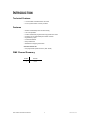
What is included
MSD-250 or
CDM-150 Discharge lamp
Warranty Card & Manual
ART-150W – Spectrum™ 150W or
ART-252W – Spectrum™ 252W & foot brackets
Power cord attached with bare ends
Unpacking Instructions
Immediately upon receiving a fixture, carefully unpack the carton, check the contents to ensure that all
parts are present, and have been received in good condition. Notify the shipper immediately and retain
packing material for inspection if any parts appear damaged from shipping or the carton itself shows signs
of mishandling. Save the carton and all packing materials. In the event that a fixture must be returned to
the factory, it is important that the fixture be returned in the original factory box and packing.
AC Power
To determine the power requirements for a particular fixture, see the label affixed to the back plate of the
fixture or refer to the fixture’s specifications chart. A fixture’s listed current rating is its average current draw
under normal conditions. All fixtures must be powered directly off a switched circuit and cannot be run off a
rheostat (variable resistor) or dimmer circuit, even if the rheostat or dimmer channel is used solely for a 0%
to 100% switch. Before applying power to a fixture, check that the source voltage matches the fixture’s
requirement. Check the fixture or device carefully to make sure that if a voltage selection switch exists that
it is set to the correct line voltage you will use.
Warning!
Verify that the power select switch on your unit matches the line voltage applied. All
fixtures must be connected to circuits with a suitable Earth Ground.
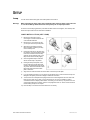
Safety Instructions
Please read these instructions carefully, which includes important
information about the installation, usage and maintenance?
•
•
•
•
•
•
•
•
Please keep this User Guide for future consultation. If you
sell the unit to another user, be sure that they also receive
this instruction booklet.
Always make sure that you are connecting to the proper
voltage and that the line voltage you are connecting to is
not higher than that stated on decal or rear panel of the
fixture.
To prevent risk of fire or shock make sure there are no
flammable materials close to the unit while operating.
The unit must be installed in a location with adequate
ventilation, at least 50cm from adjacent surfaces. Be sure
that no ventilation slots are blocked.
Always disconnect from power source before servicing or
replacing lamp or fuse and be sure to replace with same
lamp source.
Secure fixture to fastening device using a safety chain.
Never carry the fixture solely by its head. Use its carrying
handles.
Maximum ambient temperature is Ta: 50°. Do not operate
fixture at temperatures higher than this.
In the event of serious operating problem, stop using the
unit immediately. Never try to repair the unit by yourself.
Repairs carried out by unskilled people can lead to
damage or malfunction. Please contact the nearest
Caution!
•
•
•
•
•
•
•
•
•
authorized technical assistance center. Always use the
same type spare parts.
Don’t connect the device to a dimmer pack.
Make sure power cord is never crimped or damaged.
Never disconnect power cord by pulling or tugging on the
cord.
Avoid direct eye exposure to lamp while it is on.
Check your power cables carefully to ensure that
there are no cuts or breach of integrity of the outer
shell at any point. Moisture could be drawn up inside
the cable due to a vacuum generated by heat inside
the fixture.
Protect connectors for both power and data lines in a
weatherproof housing or a weatherproof junction
box.
If you don’t hard wire the fixture to a weatherproof
junction box, make sure to use an IP55 or better rated
connector for both plugs and connectors.
Do not connect to a dimmer system.
For your protection, the fixture must be grounded and
the AC mains supply must be outfitted with a circuit
breaker and ground-fault protection.
There are no user serviceable parts inside the unit. Do not open the housing or attempt
any repairs yourself. In the unlikely event your unit may require service, please contact
CHAUVET.
ART-150W & ART-252W User Manual
3
2005-01-31/12:52
INTRODUCTION
Technical Features
• 1 channel DMX controlled exterior color wash
• 2 color system creates 15 colors plus white
Features
•
•
•
•
•
•
•
•
Durable and weatherproof IP-55 rated housing
Low noise operation
4 built-in stand-alone programs with varying timed color-chase
Programs can run automatically and without controller
High efficiency optics
Frosted lens diffuser
Easy maintenance
Reliable micro-stepping motor driven
OPTIONAL CONTROLLER
• Pre-programmed: Spectrum Color™ (ART-1CON)
DMX Channel Summary
CHANNEL
FUNCTION
1
Colors
ART-150W & ART-252W User Manual
4
2005-01-31/12:52
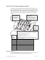
Introduction
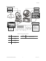
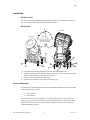
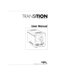
Product Overview
MSD250
Light Source
CDM150
Light Source
Head can adjust -90° ~ +90°
Head can adjust
-90° ~ +90°
Power cable provided
attached with bare ends
The DMX IN/OUT
connectors shown are for
identification only.
This product is equipped
with two internally
connected DMX cables
with applicable external
DMX connectors on both
ends.
Input/Output ports
located opposite
side of Control
Panel
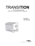
SEGMENT BUTTONS I/O PANEL OVERVIEW
I/O PANEL
BUTTONS
MENU
Toggles programming
functions
(-)
Steps backward through menu
functions
(+)
Steps forward through menu
functions
ENTER
Confirms selected menu
function
ART-150W & ART-252W User Manual
DMX Out & In
DMX-512 connectors
Product Overview
5
2005-01-31/12:52
SETUP
Lamp
You will need to install a lamp prior to the initial operation of the fixture.
Warning!
When replacing the lamp, please wait 15 minutes after powering down to allow the unit
to cool down! Always disconnect from main power prior to lamp replacement.
Do not touch the envelope (glass area) of the bulb with bare hands. If this happens, clean the lamp with
alcohol and wipe it with a lint free cloth before installation.
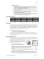
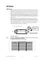
L AM P I N ST ALL AT I O N ( ART - 15 0W )
1)
Remove the lamp back cover by
removing the 4 screws located on rear
of the head as illustrated.
2)
Remove the 4 corner screws so that
you can pull out the lamp socket plate.
3)
With lamp socket plate out and the
lamp accessible, if replacing the lamp,
remove old lamp first.
4)
Holding the new lamp by its base, align
the small pin on the lamp with the small
hole in the socket and insert the lamp
squarely until the retaining clips on the
lamp socket secures the lamp tightly.
5)
Clean the glass/envelope of the bulb
with an alcohol wipe or equivalent.
6)
Holding the lamp socket plate, insert
the tip of the lamp into the fixture with
extreme care. Navigate the lamp all the
way until it reaches the reflector and the
lamp base plate touches the bottom
plate of the fixture.
1
2
3
6,7
7)
Align the screw holes and fasten the screws back onto the lamp socket plate.
8)
If you are replacing the lamp, you may want to log the fixture hours in order to track the lamps use.
Navigate to the {FhrS} on the menu display to obtain this information.
9)
Turn the fixture on and adjust the lamp alignment screws until the brightest most even area of the
beam is in the center of your spot. It may be necessary for you to use a controller in order to
command the fixture to display a white beam. Conversely you can use the {} function from the
control panel instead of a controller. Visit the “Lamp Alignement How-To” section in this manual for
further reading and tips on the subject.
10) Place the lamp cover back on the fixture and screw on securely.
ART-150W & ART-252W User Manual
6
2005-01-31/12:52
Setup
L AM P I N ST ALL AT I O N ( ART - 25 2W )
1)
Remove the lamp back cover by
removing the 4 screws located on rear
of the head as illustrated (S1).
2)
With lamp socket plate out and the
lamp accessible, if replacing the lamp,
remove old lamp first.
3)
Holding the new lamp by its base, align
the small pin on the lamp with the small
hole in the socket and insert the lamp
squarely until the retaining clips on the
lamp socket secures the lamp tightly.
S1
4)
Clean the glass/envelope of the bulb
with an alcohol wipe or equivalent.
5)
Holding the lamp socket plate, insert
the tip of the lamp into the fixture with
extreme care. Navigate the lamp all the
way until it reaches the reflector and the
lamp base plate touches the bottom
plate of the fixture.
6)
Align the screw holes and fasten the
screws back onto the lamp bank cover.
7)
If you are replacing the lamp, you may want to log the fixture hours in order to track the lamps use.
Navigate to the {FhrS} on the menu display to obtain this information.
1
Power
• To determine the power requirements for a particular fixture, see the label affixed to the back plate
of the fixture or refer to the fixture’s specifications chart.
• A fixture’s listed current rating is its average current draw under normal conditions.
• All fixtures must be powered directly off a switched circuit and cannot be run off a rheostat
(variable resistor) or dimmer circuit, even if the rheostat or dimmer channel is used solely for a 0%
to 100% switch.
• Before applying power to a fixture, check that the source voltage matches the fixture’s
requirement.
• All fixtures must be connected to circuits with a suitable Earth Ground.
ART-150W & ART-252W User Manual
7
2005-01-31/12:52
Setup
Installation
O RI E NT AT IO N
This fixture is designed to be installed upright at all times. It achieves an Ingress Protection Rating of 55
only when the fixture’s base is attached to a level horizontal surface on.
M O UNT ING
ART-252W
ART-150W
Do Not Tilt beyond -90°
and +90° as illustrated.
1)
If connected, be sure to always disconnect from main power before installing fixture.
2)
The ART-252 comes with foot brackets that should be attached to the fixture’s base prior to the fixed
installation. Bolt foot brackets to the bottom of the fixture. (A)
3)
The ART-150 is constructed with mounting brackets.
4)
Bolt fixture onto a leveled floor surface using holes marked by (B).
Power configuration
The factory power settings will be printed on the fixtures serial label. Make sure that your local AC voltage
matches that required by the fixture.
115V / 50Hz AC or
230V / 60Hz AC
Both ART-150 and ART-252 are equipped with a 3-conductor electrical cable for connecting to an AC
power supply. (D) The cable enters the fixture through a cable gland that fits 5 to 10mm diameter cables.
Because the ART fixtures are built for permanent exterior installations please adhere to the following
safety and installation precautions.
ART-150W & ART-252W User Manual
8
2005-01-31/12:52
Setup
SAFETY PRECAUTIONS!
•
Check your power cables carefully to ensure that there are no cuts or breach of
integrity of the outer shell at any point. Moisture could be drawn up inside the cable
due to a vacuum generated by heat inside the fixture.
•
Protect connectors for both power and data lines in a weatherproof housing or a
weatherproof junction box.
•
If you don’t hard wire the fixture to a weatherproof junction box, make sure to use an
IP55 or better rated connector for both plugs and connectors.
•
Do not connect to a dimmer system.
•
For your protection, the fixture must be grounded and the AC mains supply must be
outfitted with a circuit breaker and ground-fault protection.
Wiring the connector
Visible Markings
(USA) Wires
(EU) Wires
Connector
Live
“L”
Black
Brown
Yellow or brass
Neutral
“N”
White
Blue
Silver
Ground
“W”
Green
Yellow/Green
Green
Consult an electrician if you have any doubts about the proper wiring connection during your installation.
Data Cables
Data linking is required for synchronized operation as well as DMX controller operation. The Spectrum
fixtures are equipped with two 24 AWG data cables that exit the fixture through a cable gland. Both cables
are equipped with XLR connectors. The locking 3-pin male is for data input and the 3-pin female is for data
output. The “DMX Primer” in the Appendix section details more information about wiring. In short, a 3-pin
connector is wired pin-1 to (ground), pin-2 to (signal) and pin-3 to (hot).
Use RS-485 data cables designed for outdoor use.
(24 AWG) for runs up to 1000 feet or 300 meters
(26 AWG) for runs up to 1640 feet (500 meters)
Currently, neither the data cables nor the power cable is weather rated. Consider changing these for
exterior weather rated equivalents. In addition, follow the same “Safety Precautions” as listed in the section
above “Power configuration”.
Lamp Alignment How-To
Often, after a new installation of a lamp, you will find that there is an uneven field of light or what is referred
to as a hot spot. This is due to the most intense point of the lamp source not being positioned optimally
within the reflector. There are three lamp alignment screws
provided at the base of the fixture. Turning these screws
Even out this plate by
turning the lamp
allow you to optimize the projection quality of the spot as
alignment screws,
well as the overall intensity of the beam.
prior to lamp
1)
Project a white spot against any flat surface.
Preferably the surface should be white or pastel in
color.
Lamp alignment screws
optimization. This will
provide you a good
starting point.
2)
Turning the lamp alignment screws, try to position the hot spot in the center of the
beam as best as possible. This could require many attempts on your part. It is
advisable to even out the screws prior to lamp alignment as described in the
illustration.
3)
Once the hot spot is in the center of the spot, do your best to turn all screws equally as
to affect movement up or down within the reflector.
4)
As you move in and out of optimum lamp focus, you will see the hot spot either get wider
or narrower. The goal is to either totally diminish the hot spot by having it widen and spread across
the entire spot or moving the hot spot so that it covers as much of the beam spot area as possible.
ART-150W & ART-252W User Manual
9
2005-01-31/12:52
OPERATING INSTRUCTIONS
Menu Navigation
To select any of the pre-set functions, press the MENU button until the desired function is shown on the
display. Select the function by pressing the ENTER button and the display will blink. Use the DOWN and
UP button to change the settings. Once the required setting has been selected, press the ENTER button to
activate it. If you don not press the ENTER button, it will automatically return to the main functions without
any change after idling 8 seconds. To go back to the functions without any change press the MENU
button. The main functions are shown below:
DMX 512 Addressing
MENU
Sh 1 = auto-color change 5 seconds
Sh 2 = auto-color change 10 seconds
Sh 3 = auto-color change 20 seconds
Sh 4 = auto-color change 1 minute
Manual blackout
Y bo = blackout / N bo = normal
Auto-color change show
Modes 1 through 4
Manual blackout
Y bo = blackout / N bo = normal
Focus Adjust
Self test
Fixture hours
Fixture reset
Upon powering up the unit, you will notice that it will display a fixture ID. In addition, the fixtures electronics
will load up its programming and home (adjust) its motors to a starting position. The sequence of events
should take no more than 20 seconds and it is necessary for the fixture to operate correctly. During this
time you will hear motor and mechanical movement inside the fixture. After this initial power-up sequence,
if the fixture receives no DMX signal, it will enter into a stand alone mode. Be sure to power up your DMX
controller device before the lighting fixture to avoid unwanted auto mode operation.
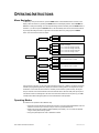
Operating Modes
All models can be operated in three different ways.
• Stand-Alone mode will allow the independent execution of programs and a Master/Slave mode will
allow the command of up to as many units you want in a synchronized manner.
• DMX control mode will provide the greatest flexibility and creativity. You can create an unlimited
range of chase patterns at any speeds
• Using the optional Spectrum Color™ dedicated controller.
ART-150W & ART-252W User Manual
10
2005-01-31/12:52
Operating Instructions
ST AN D- AL O N E
Stand-alone is an independent fixture operating state which basically means without the use of any
controlling device. The Spectrum™ Exterior Wash fixtures have 4 internal programs that can be manually
selected using the fixture’s Control Panel. Once set, every time the fixture is powered, the program
selected will automatically execute. Selecting the program is done using the {ShNd} function in the fixture’s
Control Panel. Skip over to “Menu Functions” – “Stand-Alone, Show Selection {ShNd}” for detailed
instructions. If you own multiple Spectrum™ fixtures, you can link them together so that they all follow one
leader in synchrony called the (master). This operating state is called Master/Slave mode.
The Master/Slave mode will allow you to link multiple units in a daisy chain fashion. In this mode, the first
unit in the daisy chain will automatically command all other units following. Master/Slave operation does
not require any menu or setting selections. Simply connect each fixture in a daisy like fashion using
qualified 3 pin DMX cables as described below. The first unit in the chain will operate in a Stand-Alone
mode and all units following will synchronize to the first unit. You can choose from 4 internal chase
programs as described in the next page under “Stand-Alone, Show Selection {ShNd}”.
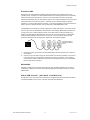
Daisy Chain Connection
also applies to DMX-512
control.
Optional
1)
Connect the (male) 3 pin connector side of the DMX cable to the output (female) 3 pin connector of
the first fixture.
2)
Connect the end of the cable coming from the first fixture which will have a (female) 3 pin connector
to the input connector of the next fixture consisting of a (male) 3 pin connector. Then, proceed to
connect from the output as stated above to the input of the following fixture and so on as illustrated
below in “Daisy Chain Connection”.
DM X M O DE
Operating in a DMX Control mode environment gives the user the greatest flexibility when it comes to
customizing or creating an environment. Simply address all fixtures sequentially and use any universal
DMX controller.
S P ECT R UM CO L O R ™ (O PT IO N AL CO NT RO LLE R)
The Spectrum Color™ is the ideal control mechanism for the Spectrum series Architectural wash fixtures.
It provides immediate access to colors, color holds, and timed chase adjustment.
ART-150W & ART-252W User Manual
11
2005-01-31/12:52
Operating Instructions
Menu Functions
DMX-512 addressing {Addr}
This mode enables the use of a universal DMX controller device. Each fixture requires a "start address"
from 1 to 511. A fixture requiring one or more channels for control begins to read the data on the channel
indicated by the start address. In the case of the Spectrum™, only 1 channel is necessary. Each fixture
can be incrementally numbered.
The following Caution statement refers to Universal DMX Controller devices only.
Some controllers are factory configured to control a specific range of channels per fixture. For example, you may
have a controller pre-set to control 10 channels per fixture for a total of 12 fixtures. In this case you would be
required to separate all fixtures in 10 channel increments instead of the true number of channels your particular
fixture utilizes.
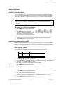
S ET T ING T H E ST ART ING AD D R E SS
1)
Press the MENU button until the display reads
.
2)
Press the ENTER button to select DMX
addressing. Once selected the display will read
either a 1 or any other number that may have
previously been set. You must make a selection
within 6 seconds.
3)
Press the (-) and (+) buttons to increase or decrease values until the desired value is achieved.
4)
Press the ENTER button to activate selection.
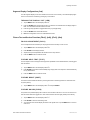
Stand-Alone, Show Selection {ShNd}
By linking the units under a Show mode, the first unit can direct additional units to create a synchronized
light show. If the fixture is not connected to a controller then it will automatically enter a stand-alone mode.
S ET T ING T H E S HO W
The Spectrum™ contains 4 built in programs that affect the time that each color changes
.
.
1)
2)
Show Mode 1
5 second color chase
Show Mode 2
10 second color chase
Show Mode 3
20 second color chase
Show Mode 4
1 minute color chase
Tap the MENU button until the display reads .
Press the ENTER button to select this function. The selection is confirmed when the display begins to
blink. You must make a selection within 8 seconds.
3)
Press the (-) and (+) buttons to toggle between the Shows available.
4)
Press the ENTER button to activate selection.
Blackout Mode {bLNd}
1)
Tap the MENU button until the display reads .
2)
Press the ENTER button to select this function. The selection is confirmed when the display begins to
blink. You must make a selection within 8 seconds.
3)
Press the (-) and (+) buttons to toggle between [ ] for yes to blackout or [ ] for no.
4)
Press the ENTER button to activate selection.
ART-150W & ART-252W User Manual
12
2005-01-31/12:52
Operating Instructions
Segment Display Configurations {Led}
The LED segment display can be set to off after 8 seconds of no menu activity. The LED will display again
as soon as the menu is accessed by pressing any of the buttons.
T URNI NG T H E D I SP L AY O F F {L E D}
1)
Tap the MENU button until the display reads .
2)
Press the ENTER button to select this function. The selection is confirmed when the display begins to
blink. You must make a selection within 8 seconds.
3)
Press the (-) and (+) buttons to toggle between the {on} and {off} setting.
4)
Press the ENTER button to activate selection.
5)
Note! This configuration is set on an individual fixture basis.
Fixture Test and Service Functions {FAdJ}, {teSt}, {FhrS}, {rSet}
F O CU S AD J U ST M ENT {F AD J }
The focus adjustment tool activates a pre-set program that turns the lamp on with no color.
1)
Tap the MENU button until the display reads .
2)
Press ENTER and the display will blink.
3)
Adjust the lamp focus/optimization as described in the “Lamp Section”.
4)
Press the MENU button to leave this mode.
F I XT UR E S EL F- T E ST {T E ST }
The test sequence will run through all of the projection capabilities of each individual fixture, including gobo
and color effects.
1)
Tap the MENU button until the display reads .
2)
Press ENTER and the fixture will immediately begin to play back a test sequence. Observe tentatively
for any abnormalities.
3)
Press the MENU button to leave this mode.
F I XT UR E R E S ET { R S ET }
This function will re-initialize the fixture by returning all motors to its startup positions or otherwise known
as (home position).
1)
Tap the MENU button until the display reads and press ENTER.
F I XT UR E HO UR S {F H RS }
The (fixture hours) readout displays the number of hours the fixture has been in use. It is not uncommon to
find new fixtures with a few logged hours. This means the fixture was thoroughly tested prior to delivery.
1)
Tap the MENU button until the display reads .
2)
Press ENTER to view the total working hours.
3)
You can leave alone and the display will return to the regular menu or press MENU button to return to
main menu.
ART-150W & ART-252W User Manual
13
2005-01-31/12:52
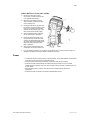
Spectrum Color™ (Optional dedicated controller)
The ART-1CON is a user friendly dedicated controller for the Spectrum Architectural Exterior Wash. It
allows the user to select manually any one of 10 colors on buttons or any of the 15 available colors using
the slider including the color scroll effect. The controller can be set to hold any particular color or the timedchase can be modified between .01 seconds and 10 minutes. There are 10 built in chase patterns to
choose from. Unless you intend to hold a color for a full day, to extend the time period beyond 10 minutes
use a universal DMX controller. Visit www.chauvetlighting.com and browse the section under DMX
Controllers.
Color & Number Buttons
Speed & Color Slider
These buttons are not only
used for the selection of a
color or chase patterns but
as a numerical keypad
when remote addressing
fixtures.
When Chase button is activated, use
this slider to adjust the chase speed
from .01 to 10 minutes. When in Hold
use to access all colors available on the
Spectrum, including a color scroll.
Hold
Enables the color
selection aspect
of the
Color/Numbers
buttons
Chase
Pressing this buttons enables the pattern chase select using the Color/Numbers
buttons. The following 3 chase modes can also be set:
One way (LED On); color changes occur in one direction
Example: color 1,2,3,4,5 etc. color 1,2,3,4,5 etc.
Blackout
Temporarily
eliminated light
output from the
fixture.
Chase Patterns
Loop (LED blinks fast); color changes in forwards then reverse order
Example: color 1,2,3,4,5 ~ etc. ~ 5,4,3,2,1
Manual (LED blinks slowly); you can manually step through the scenes in a program
Example: press any one program button repeatedly to advance to the next step within the program
until the desired look is achieved.
Chase Pattern Description
1
Changes colors at random
2
Group changing colors – one by one
3
Group changing colors – two by two
4
Group changing colors – four by four
5
Group changing colors – eight by eight
6
Group changing colors – 16 by 16
7
Color chasing – one fixture after another in sequence
8
Color chasing – 2 after 2 in sequence
9
Color chasing – 4 after 4 in sequence
0
Color chasing – 8 after 8 in sequence
Auto Fixture Address
Hold down the BLACKOUT button and use the Color/Number buttons to enter the number of fixtures you
have daisy chained. Upon releasing, the fixtures will be automatically addressed.
ART-150W & ART-252W User Manual
14
2005-01-31/12:52
APPENDIX
DMX Primer
There are 512 channels in a DMX-512 connection. Channels may be assigned in any manner. A fixture
capable of receiving DMX-512 will require one or a number of sequential channels. The user must assign a
starting address on the fixture that indicates the first channel reserved in the controller. There are many
different types of DMX controllable fixtures and they all may vary in the total number of channels required.
Choosing a start address should be planned in advance. Channels should never overlap. If they do, this
will result in erratic operation of the fixtures whose starting address is set incorrectly. You can however,
control multiple fixtures of the same type using the same starting address as long as the intended result is
that of unison movement or operation. In other words, the fixtures will be slaved together and all respond
exactly the same.
DMX fixtures are designed to receive data through a serial Daisy Chain. A Daisy Chain connection is
where the DATA OUT of one fixture connects to the DATA IN of the next fixture. The order in which the
fixtures are connected is not important and has no effect on how a controller communicates to each fixture.
Use an order that provides for the easiest and most direct cabling. Connect fixtures using shielded two
conductor twisted pair cable with three pin XLR male to female connectors. The shield connection is pin 1,
while pin 2 is Data Negative (S-) and pin 3 is Data positive (S+). CHAUVET carries 3-pin XLR DMX
compliant cables, DMX-10 (33’), DMX-4.5 (15’) and DMX-1.5 (5’)
Figure 1 - DMX connector configuration
1
3
2
COMMON
1
3
INPUT
1
3
DMX +
2
2
DMX -
Resistance 120
ohm 1/4w between
pin 2 (DMX -) and
pin 3 (DMX +) of
the last fixture.
OUTPUT
Termination reduces signal errors and to
avoid signal transmission problems and
interference, it is always advisable to
connect a DMX signal terminator.
F I XT UR E L I NK ING
Note!
If you use a controller with a 5 pin DMX output connector, you will need to use a 5 pin to
3 pin adapter. CHAUVET Model No: DMX5M.
The chart below details a proper cable conversion:
3 PIN TO 5 PIN CONVERSION CHART
Conductor
3 Pin Female (output)
5 Pin Male (Input)
Ground/Shield
Pin 1
Pin 1
Data ( - )signal
Pin 2
Pin 2
Data ( + ) signal
Pin 3
Pin 3
Do not use
Do not use
Do not use
Do not use
ART-150W & ART-252W User Manual
15
2005-01-31/12:52
Appendix
DMX Channel Values
CHANNEL
1
VALUE
000
008
016
023
031
038
046
053
061
068
076
083
091
098
106
113
121
128
248
007
015
022
030
037
045
052
060
067
075
082
090
097
105
112
120
127
247
255
FUNCTION
Colors
Blackout
White
CT-3200°K
Red
CT & Red
Orange
Yellow
Amber
Dark Green
Green
CT & Green
Light Green
Cyan
Blue
CT & Blue
Purple
Pink
Rainbow effect
White
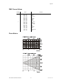
Photo Metrics
ART-150W & ART-252W User Manual
16
2005-01-31/12:52
Appendix
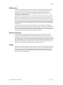
Maintenance
To maintain optimum performance and minimize wear fixtures should be cleaned frequently. Usage and
environment are contributing factors in determining frequency. As a general rule, fixtures should be
cleaned at least twice a month. Dust build up reduces light output performance and can cause
overheating. This can lead to reduced lamp life and increased mechanical wear. Be sure to power off
fixture before conducting maintenance.
Unplug fixture from power. Use a vacuum or air compressor and a soft brush to remove dust collected on
external vents and internal components. Clean all glass when the fixture is cold with a mild solution of
glass cleaner or Isopropyl Alcohol and a soft lint free cotton cloth or lens tissue. Apply solution to the cloth
or tissue and drag dirt and grime to the outside of the lens. Gently polish optical surfaces until they are free
of haze and lint. Do not to touch the lamp glass when cleaning fixture. Oil and dirt can cause damage and
premature aging of the lamp. In the event that the lamp is touched or becomes dirty, clean the lamps with
an alcohol wipe.
The cleaning of internal and external optical lenses and/or mirrors must be carried out periodically to
optimize light output. Cleaning frequency depends on the environment in which the fixture operates: damp,
smoky or particularly dirty surrounding can cause greater accumulation of dirt on the unit’s optics. Clean
with soft cloth using normal glass cleaning fluid. - Always dry the parts carefully. - Clean the external optics
at least every 20 days. Clean the internal optics at least every 30/60 days.
Returns Procedure
Returned merchandise must be sent prepaid and in the original packing, call tags will not be issued.
Package must be clearly labeled with a Return Merchandise Authorization Number (RA #). Products
returned without an RA # will be refused. Call CHAUVET and request RA # prior to shipping the fixture. Be
prepared to provide the model number, serial number and a brief description of the cause for the return. Be
sure to properly pack fixture, any shipping damage resulting from inadequate packaging is the customer’s
responsibility. CHAUVET reserves the right to use its own discretion to repair or replace product(s). As a
suggestion, proper UPS packing or double-boxing is always a safe method to use.
Claims
Damage incurred in shipping is the responsibility of the shipper; therefore the damage must be reported to
the carrier upon receipt of merchandise. It is the customer's responsibility to notify and submit claims with
the shipper in the event that a fixture is damaged due to shipping. Any other claim for items such as
missing component/part, damage not related to shipping, and concealed damage, must be made within
seven (7) days of receiving merchandise.
ART-150W & ART-252W User Manual
17
2005-01-31/12:52
Appendix
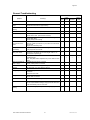
General Troubleshooting
Applies to
Symptom
Solution(s)
Auto shut off
Check fan thermal switch reset
Beam is very dim or not
bright
Clean optical system or replace lamp
Check 220/110v switch for proper setting
Breaker/Fuse keeps
blowing
Check total load placed on device
Chase is too slow
Check users manual for speed adjustment
Device has no power
Check for power on Mains.
Check device’s fuse. (internal and/or external)
Lights
Foggers
& Snow
Controllers
Dimmers
& Chaser
Fixture is not responding Check DMX Dip switch settings for correct addressing
Check DMX cables
Check polarity switch settings
Fixture is on but there is
no movement to the
audio
Make sure you have the correct audio mode on the control
switches. If audio provided via ¼” jack, make sure a live audio
signal exists
Adjust sound sensitivity knob
Lamps cuts off
sporadically
Possible bad lamp or fixture is overheating.
Lamp may be at end of its life.
Light will not come on
after power failure
Some discharge lamps require a cooling off period before the
electronics in the fixture can kick start it again, wait 5 to 10
minutes before powering up
Loss of signal
Use only DMX cables
Install terminator
Note: Keep DMX cables separated from power cables or black
lights.
Motor movements are
jerky or jumpy
Possible bad motor driver or sensors
Check polarity switch on controller
Moves slow
Check 220/110v switch for proper setting
No flash
Re-install bulb, may have shifted in shipping
No light output
Check slip ring & brushes for contact
Install bulb
Call service technician
Relay will not work
Check reset switch
Check cable connections
Remote does not work
Make sure connector is firmly connected to device
Stand alone mode
All CHAUVET lighting fixtures featuring stand-alone functions
do not require additional settings, simply power the fixture and
it will automatically enter into this mode
Unit wobbles when
rotating
Check for damages possibly incurred during shipping
ART-150W & ART-252W User Manual
18
2005-01-31/12:52
Appendix
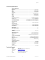
Technical Specifications
WEIGHT & DIMENSIONS
(ART-150W)..........................................................................................................................................
Length.............................................................................................................................203 mm (8 in)
Width............................................................................................................................. 330 mm (13 in)
Height ........................................................................................................................... 457 mm (18 in)
Weight..........................................................................................................................12.7 Kg (28 lbs)
(ART-252W)..........................................................................................................................................
Length..................................................................................................................... 266.7 mm (10.5 in)
Width............................................................................................................................. 381 mm (15 in)
Height ........................................................................................................................ 533.4 mm (21 in)
Weight........................................................................................................................21.77 Kg (48 lbs)
POWER
Power settings (internal tap)........................................................................115V 60 Hz or 230V 50 Hz
AC input .........................................................................................................3 prongs IEC 60320 C14
European version ............................................................................................................... 240V 50 Hz
Current draw (ART-150W)............................................. (peak 180W @ 120V), (inrush 352W @ 120V)
Current draw (ART-252W)............................................. (peak 266W @ 120V), (inrush 520W @ 120V)
LAMP (ART-150W)
CDM150............................................................................................................ 5000 hr, 4200K, 150W
LAMP (ART-252W)
CHAUVET US-HSD-250 ................................................................................... 2000 hr, 6000K, 250W
Philips MSD-250/2 ............................................................................................ 2000 hr, 6500K, 250W
Philips MSD-200 ............................................................................................... 2000 hr, 5600K, 200W
PHOTO OPTIC
Beam Angle (ART-150W)................................................................................................................ 30°
Beam Angle (ART-252W)................................................................................................................ 45°
THERMAL
Maximum ambient temperature ......................................................................................... 50° (122° F)
CIRCUIT PROTECTION
ART-150 Fuse 1........................................................................................... 3A 250V Fast Blow (PCB)
ART-150 Fuse 2......................................................................................... 7A 250V Fast Blow (Mains)
ART-252 .....................................................................................6A Magnetic Circuit Breaker with GFI
CONTROL & PROGRAMMING
Data input ............................................................................................. locking 3-pin XLR male socket
Data output ........................................................................................ locking 3-pin XLR female socket
Data pin configuration ............................................................................pin 1 shield, pin 2 (-), pin 3 (+)
Protocols.....................................................................................................................DMX-512 USITT
DMX Channels ....................................................................................................................................1
ORDERING INFORMATION
Spectrum™ 150W............................................................................................................... ART-150W
Spectrum™ 252W............................................................................................................... ART-252W
Fuse 3A 250V ............................................................................................................... P170FUSE003
Fuse 7A 250V ............................................................................................................... P170FUSE007
OPTIONS
Spectrum Color™................................................................................................................ART-1CON
Technical Support
Address:
Support (Email):
Telephone:
Fax:
Website:
ART-150W & ART-252W User Manual
Service Dept.
3000 N 29th Ct, Hollywood, FL 33020 (U.S.A.)
[email protected]
(954) 929-1115 - (Press 4)
(954) 929-5560 - (Attention: Service)
http://www.chauvetlighting.com
19
2005-01-31/12:52