1
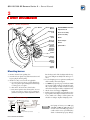
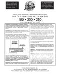
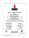
QB-180/300 Oil Burners — Series 2 For Weil-McLain GO, 66 & 68 Boilers Burner Manual Patent 5,961-316 Read all instructions before installing This manual must only be used by a qualified heating installer/service technician. Failure to comply could result in severe personal injury, death or substantial property damage. Installer Leave all documentation with burner for future reference. User Burner must be installed and annually serviced by a qualified installer/service technician. Part number 644-500-065/0200 QB-180/300 Oil Burners Series 2 — Burner Manual !!! IMPORTANT! Read this page first Hazard definitions The following defined terms are used throughout this manual to bring attention to the presence of hazards of various risk levels or to important information concerning the life of the product. Indicates presence of hazards that will cause severe personal injury, death or substantial property damage. Indicates presence of hazards that will or can cause minor personal injury or property damage. Indicates presence of hazards that can cause severe personal injury, death or substantial property damage. Indicates special instructions on installation, operation or maintenance that are important but not related to personal injury or property damage. Read and follow instructions below to install or service the burner to reduce risk of severe personal injury, death or substantial property damage. 2 • Appliance must be connected to a flue with sufficient draft at all times to assure proper operation. • Always keep manual fuel supply valve shut off if burner is shut down for an extended period of time. • Do not use crankcase drainings or any oil containing gasoline as it is more combustible than No. 1 or No. 2 fuel oil. • Do not start burner unless flue collector hood, jacket cap, flue cap and burner mounting door are secured in place. • Do not attempt to start burner when excess oil has accumulated in combustion chamber, when boiler is full of vapor, or when combustion chamber is very hot. • Never burn garbage or paper in the appliance. • Never leave combustible material around appliance. Part number 644-500-065/0200 QB-180/300 Oil Burners Series 2 — Burner Manual Contents Hazard definitions .................................................................................... 2 Table of contents ...................................................................................... 3 1 Pre-installation considerations ................................................................ 4 2 Burner installation ................................................................................... 5 3 Fuel pumps and oil lines .......................................................................... 8 4 Wiring, operation and service ................................................................ 11 5 Troubleshooting ..................................................................................... 12 6 Parts list ................................................................................................. 14 Weil-McLain Limited Warranty .................................................. Back cover Part number 644-500-065/0200 3 QB-180/300 Oil Burners Series 2 — Burner Manual 1 Pre-installation considerations Codes and standards • • • Install burner in accordance with NFPA 31, Standard for Oil-Burning Equipment and all local codes and regulations of authorities having jurisdiction. In Canada, refer to CSA B139, Installation Code for Oil-Burning Equipment. Regulations of these authorities take precedence over instructions in this manual. All wiring must comply with National Electrical Code and local ordinances; in Canada, CSA C22.1 Canadian Electrical Code Part One and any local codes. Refer to wiring diagram in Control Supplement supplied with burner. Underwriters Laboratories has certified this burner to comply with ANSI Standard 296.6 and has listed it for use with No. 1 or No. 2 fuel oil as specified in ASTM D396. Chimney or vent Inspect existing chimney or vent before installing new burner. Failure to do the following will cause severe personal injury or death. • Clean chimney, including removal of blockage. • Repair or replace damaged pipe or liner. • Repair mortar and joints. Set the over-fire draft to the appliance manufacturer’s recommended setting if available, or to -0.01" to -0.02" water column. Install barometric control in breeching, per control manufacturer’s instructions, when excess draft needs to be relieved or to comply with applicable codes and regulations. Use draft gauge to adjust proper opening. 4 Combustion and ventilation air openings See appliance manual and NFPA 31, Standard for OilBurning Equipment for details. For recommended practice in Canada, refer to CSA Standard B139. Adequate combustion and ventilation air must be provided to assure proper combustion and reduce risk of flue gas leakage and carbon monoxide emissions, leading to severe personal injury or death. When the boiler is installed in a confined space (volume of space less than 50 cubic feet per 1,000 Btuh input of all appliances in space), two permanent openings must be provided: • • • One near the top of the enclosure One near the bottom. Each opening must have a free area of not less than one (1) square inch per 1,000 Btuh (140 square inch per gph), of the total input rating of all the appliances in the space. When building is of unusually tight construction, has a kitchen ventilating system, exhaust fans, clothes dryer or vented fireplaces, it may be necessary to duct outside air directly to the burner in order to support clean combustion. Weil-McLain QB-A1 Outside Air Kit, part number 644-500-056, provides outside air directly to the burner. • If QB-180 or QB-300 Oil Burner is received separately for field installation, proceed to page 5, Burner Installation. • If QB-180 or QB-300 Oil Burner is received installed on the boiler, proceed directly to page 8, Fuel Pumps and Oil Lines. Part number 644-500-065/0200 QB-180/300 Oil Burners Series 2 — Burner Manual 2 Burner installation Figure 1 Burner components Ignition Wires “E” Clip Nozzle Adapter Wrench 3/16“ Oil Line GUN ASSEMBLY Includes: Adjustment Cam Adjustment Cam Captive Screw Electrode Assembly Top Leg of Spinner Centered Vertically Between Electrodes Electrode Assembly Spinner Assembly Nozzle Nozzle Adapter Oil Line Ignition Wires Nozzle Spinner Assembly Spinner Clamping Screw Nozzle Adapter 06502 Mounting burner 1. Remove burner from packing box. 2. Detach and save plastic bag with instructions and bypass plug from fuel pump. 3. Install or verify correct nozzle as applicable: a. Loosen, but do not remove, screw holding housing cover plate in place. Pull ignitor back and up to swing open cover plate. b. Disconnect oil line from solenoid valve. c. Disconnect ignition wires from ignitor. Loosen, but do not remove, captive screw securing adjustment cam in place. Turn adjustment cam so Figure 2 Electrode settings 5/16“ 1/8“ between electrode tips d. e. f. g. that the larger end of the slot aligns with the captive screw. Pull gun assembly back and up to remove. Loosen clamping screw on spinner assembly and slide assembly off nozzle adapter. See Table 1 on page 6 for proper nozzle size. Make sure nozzle is tight in adapter (110 in-lbs nominal). Nozzle adapter wrench in burner housing can hold nozzle adapter while you tighten nozzle. Check electrode settings per Figure 2. Replace spinner assembly on nozzle adapter. Top leg of spinner must align vertically between electrodes. Make sure clamp is back against the shoulder on adapter. Tighten clamping screw. from tip of electrode to centerline of nozzle 1/16“ from tip of nozzle to tip of electrode Part number 644-500-065/0200 06501 Fuel pump is factory set at 140 psig (QB-300) or 150 psig (QB-180). Use of a nozzle selected for 100 psig pressure could result in severe personal injury, death or substantial property damage. 5 QB-180/300 Oil Burners Series 2 — Burner Manual 2 Burner installation continued Table 1 Boiler model Burner nozzle selection Use only the nozzles specified. QB-180 burner nozzle size (Pump pressure is 150 psig) Preferred Alternates Air band setting Delavan Hago 0.65 70˚ A 0.65 70˚ B 0.65 70˚ AS 0.65 70˚ S 150 0.70/0.95 3.25 GO-3 0.85 70˚ A 0.85 70˚ B 0.85 70˚ AS 0.85 70˚ S 150 0.70/0.95 5.25 GO-4 1.00 70˚ B 1.00 70˚ B 1.00 70˚ AS 1.00 70˚ S 150 1.20 5.50 GO-5 1.25 60˚ B 1.25 45˚ B 1.25 60˚ AS 1.25 70˚ S 150 1.45 6.25 GO-6 1.50 45˚ B 1.50 45˚ B - 1.50 45˚ S 150 1.75 6.75 268 * 0.65 70˚ A 0.65 70˚ H - 0.65 70˚ H 150 0.70/0.95 3.00 368 0.85 70˚ A - 0.85 70˚ AH 150 0.70/0.95 5.00 468 1.10 70˚ A 1.10 70˚ ES 150 1.20 5.25 568 1.25 60˚ B 1.25 70˚ B 150 1.45 6.00 668 1.50 45˚ B 1.50 60˚ B or 1.50 45˚ ES 266 * 0.65 70˚ A 0.65 70˚ H 366 0.85 70˚ A 466 566 666 - 1.10 70˚ AS 1.10 80˚ S 1.25 60˚ AS - 1.50 60˚ AS 1.50 60˚ S 150 1.75 6.50 - 0.65 70˚ H 150 0.70/0.95 3.00 0.85 70˚ B 0.85 70˚ AS - 150 0.70/0.95 5.00 1.10 70˚ A 1.10 60˚ H 1.10 70˚ AH 1.10 70˚ H 150 1.20 5.25 1.25 60˚ B 1.25 70˚ B 1.25 60˚ AS 150 1.45 6.00 1.50 45˚ B 1.50 60˚ B or 1.50 45˚ ES 150 1.75 6.50 * Install baffle clip per instructions packed with kit. 1. Nozzle: Tighten to 110 in/lbs. 2. Nozzle types: A, AH, H = hollow; SS = semi-solid B, ES, R, S, AS = solid - 1.50 60˚ AS 1.50 60˚ S 3. Suggested settings are for set-up with listed nozzle sizes only. Final adjustments must be made with combustion test equipment and should provide zero smoke with proper CO2. 4. For I=B=R boiler capacity, refer to individual boiler manual. QB-300 burner nozzle size (Pump pressure is 140 psig) Preferred Alternates Pump Cam Air band pressure setting setting (psig) Hago Delavan Steinen GO-6 1.50 60˚ B or 1.50 45˚ B 1.50 45˚ B 1.50 60˚ S 140 1.75 2.25 GO-7 1.75 60˚ B or 1.75 45˚ B 1.75 60˚ B 1.75 70˚ S 140 2.00 3.75 GO-8 2.00 60˚ P or 2.00 45˚ P 2.00 70˚ B 2.00 70˚ S 140 2.30 5.75 GO-9 2.25 60˚ P or 2.25 45˚ P 2.25 60˚ B or 2.25 45˚ B 2.25 60˚ S 140 2.55 5.25 668 1.50 60˚ B or 1.50 45˚ B 1.50 45˚ B 1.50 60˚ S 140 1.75 2.25 768 1.75 60˚ B or 1.75 45˚ B 1.75 60˚ B 1.75 70˚ S 140 2.00 3.75 868 2.00 45˚ P 2.00 70˚ B 2.00 70˚ S 140 2.30 5.75 968 2.25 60˚ P 2.25 60˚ B 2.25 60˚ S 140 2.55 5.25 666 1.50 60˚ B or 1.50 45˚ B 1.50 45˚ B 1.50 60˚ S 140 1.75 2.25 766 1.75 60˚ B or 1.75 45˚ B 1.75 60˚ B 1.75 70˚ S 140 2.00 3.75 866 2.00 45˚ P 2.00 70˚ B 2.00 70˚ S 140 2.30 5.75 966 2.25 60˚ P 2.25 60˚ B 2.25 60˚ S 140 2.55 5.25 1. Suggested settings are for set-up with listed nozzle sizes only. Final adjustments must be made with combustion test equipment and should provide zero smoke with proper CO2. 2. For I=B=R boiler capacity, refer to individual boiler manual. 6 Steinen Cam setting GO-2 Boiler model Danfoss Pump pressure (psig) 3. Nozzle types: B, ES, P, S = solid 4. Nozzle: Tighten to 110 in/lbs. Part number 644-500-065/0200 QB-180/300 Oil Burners Series 2 — Burner Manual Adjustment cam setting 1.75 1.45 1.2 0 Screw indicates setting 5 GPH 1.7 0 2.5 5 4. Reinstall gun assembly: a. Insert gun assembly into burner – do not force it. The gun assembly must be lifted and guided into air cone at end of air tube. b. Turn adjustment cam so that the larger end of the slot drops over the captive screw. c. Position gun assembly by rotating adjustment cam (Figure 3) to correct setting. See Table 1, page 6, for correct adjustment cam setting. Tighten captive screw to lock adjustment cam in place. d. Connect oil line to solenoid valve. e. Connect ignition wires to ignitor. f. Swing cover plate closed and push forward to engage locking pins. g. Tighten screw holding housing cover plate in place. 5. Mount burner to boiler with gasket supplied. 6. Verify attenuating air band setting. See Table 1, page 6, and Figure 4. Figure 3 GP 2.2 H 2.00 Burner settings QB 180 0.95 0.70 QB-180 cam shown QB-300 cam 06503 Attenuating air band setting O PE 7 8 9 TO T OP ALLY EN Figure 4 N 6 5 E OS CL 4 3 2 1 0LLY Starting settings in Table 1 are for setup only. Final adjustments must be made with combustion test equipment and should provide zero smoke with proper CO2. See Final adjustments on page 11. Adjust the air band setting first. If adjustments of the air band do not result in clean combustion, then adjust the cam setting. Increase the setting to increase air. Decrease the setting to reduce air. Cam adjustments should be minor only. Part number 644-500-065/0200 TOTA D CLOSE 06504 7 QB-180/300 Oil Burners Series 2 — Burner Manual 3 Fuel pumps and oil lines General All installations must comply with national or local codes and ordinances. Oil line must be piped properly to avoid risk of serious personal injury, death or substantial property damage. Follow these recommendations: • • • • • When installing oil lines, use continuous runs of heavy-wall copper tubing. Be sure all connections are airtight. Flared fittings are recommended. Do not use compression fittings. Do not use Teflon tape. Use an oil filter of adequate size for all installations. Install filter inside building between tank shutoff valve and burner. For easy servicing, locate shutoff valve and filter near burner. Long or oversized inlet lines may require the pump to operate dry during initial bleeding period. In such cases, assist priming by injecting fuel oil into pump gearset. Never exceed 3 psi pressure to inlet side of pump. Pressure over 3 psi may damage shaft seal and allow it to leak oil. port. Do not use easy flow air bleed valve. It contains higher pressure than operating pressure. Setting pump pressure with gauge in easy flow air bleed valve will result in wrong operating pressure. Average cutoff pressure is 120 psig. Check cutoff pressure by installing pressure gauge in nozzle port of fuel pump. Run burner for short time. Shut off burner. Gauge shows cutoff pressure. Figure 5 Fuel pump — Typical Solenoid valve Solenoid valve supplied in nozzle line is a non-delay valve and provides instant oil supply shutoff to nozzle. Inlet ¼" npt (2 locations) Return ¼" npt Vacuum gauge Vacuum gauge may be installed in either of the ¼" inlet ports. Vacuum is total of all pressure drops in system from tank to pump inlet. Easy flow air bleed valve Oil pump pressure Regulating pressure (behind inlet) To check operating pressure, use gauge port or nozzle 8 Solenoid valve Nozzle port 1/8" npt (read operating pressure) Pressure gauge port 1/8" npt (read operating pressure) 1/16" bypass plug — insert for two-pipe systems ONLY (use 5/32" allen wrench) 06505 Part number 644-500-065/0200 QB-180/300 Oil Burners Series 2 — Burner Manual One-pipe oil systems (Figure 6) Figure 6 One-pipe oil system, typical Use one-pipe oil piping only when: • the fuel is gravity fed — or — • the fuel must be lifted no more than 8 feet. See Figure 6. (If the fuel lift is greater than 8 feet use twopipe fuel piping — Figure 7 on page 10.) • fuel suction line vacuum is less than 6" Hg for either a single-stage or two-stage burner fuel pump. Air vent Fuel pump Filter Fill pipe Burner fuel pump bypass plug must not be used with one-pipe installations. One-pipe installations must be absolutely air tight to prevent leaks or loss of prime. Bleed line and fuel pump completely. Bleed for 15 seconds after last air bubble is seen from easy flow air bleed valve to be certain lines are air free. When bleeding oil pumps on burners equipped with lockout-type controls, you may have to cycle the burner several times to complete purging. Shutoff valve Maximum one-pipe system lift = 8 feet Oil tank Inlet 06506 Part number 644-500-065/0200 9 QB-180/300 Oil Burners Series 2 — Burner Manual 3 Fuel pumps and oil lines continued Figure 7 Two-pipe oil system, typical to a fuel lift height of no more than 10 feet. For greater lifts install a two-stage pump on the burner. Return line L Fuel suction line vacuum must not exceed 12" Hg for a single-stage pump or 17" for a two-stage pump. (lift) Bypass plug must be used with two-pipe installations. Oil tank Remove plug from plastic bag attached to fuel pump. Remove ¼" plug from return port. Insert bypass plug. Attach return and inlet lines. Air vent Burner fuel pump — A single-stage pump is limited Inlet line Fill pipe Filter Inlet line Fuel pump Use two-pipe installations when fuel must be lifted greater than 8 feet. Return line Two-pipe oil systems (Figure 7) Always terminate return line as shown in Figure 7. To determine two-pipe maximum line lengths, use Table 2, page 10. Table 2 06507 Return line terminates 3 to 4 inches above inlet line Two pipe oil system maximum oil line lengths (feet) Single-stage oil pump Two-stage oil pump Lift “L” 3/8" O.D. 1/2" O.D. 3/8" O.D. 1/2" O.D. 0 84 100 93 100 2 73 100 85 100 4 63 100 77 100 6 52 100 69 100 8 42 100 60 100 10 31 100 52 100 44 100 36 100 27 93 -- 65 12 14 16 Not recommended — use two-stage pump 18 Note: Line lengths include total of vertical and horizontal lengths. 10 Part number 644-500-065/0200 QB-180/300 Oil Burners Series 2 — Burner Manual 4 Wiring, operation and service Wiring Service Wire the burner (and boiler) following instructions in the burner Control Supplement and the Boiler Manual. Start-up Read the sequence of operation and start-up procedures in the burner Control Supplement. Final Adjustments You must use test instruments to properly start, check and adjust burner. Failure to do so could result in severe personal injury, death or substantial property damage. 1. Make sure combustion and ventilation air supply is sufficient for normal appliance operation. Close windows and doors in appliance area to simulate normal job condition. Start boiler and allow for a 10-minute warm up. 2. Check for -.01" to -.02" W.C. draft in combustion chamber. Adjust barometric damper as necessary. 3. Check for 0 smoke. 4. Check for CO2 between 11% and 12 ½%. • To increase CO2, close attenuating air band setting. • To decrease CO2, open attenuating air band setting. 5. Check CO2, smoke and draft levels again. 6. Start and stop unit several times. 7. Check operation of limits, thermostats and timing of combustion control. 8. Check for oil leaks. 9. Recheck all installations after one to two weeks of operation. Electrical shock hazard. Failure to shut off electrical supply before servicing can cause severe personal injury, death or substantial property damage. 1. See Boiler Service/Maintenance Guide for details of annual service call, including cleaning boiler flueways. 2. Oil blower motor (if required). Refer to motor name plate/specifications label for any instructions. 3. Replace oil filter cartridge once a year to prevent fuel oil contamination from plugging fuel pump and nozzle. 4. Replace nozzle once a year before start up of heating season. Always use proper nozzle. See Table 1 on page 6. 5. Check electrode settings once a year. See page 5. 6. Clean fan and blower housing regularly to keep free of dirt and lint. 7. Check and adjust burner according to Start-up procedures in Control Supplement after each servicing. 8. Contact your Weil-McLain distributor for all burner parts that need replacement. When servicing a NO HEAT call: Check each item below, making sure to complete each check before going to the next one. ❏ Thermostat(s). ❏ Main fuse and power supply. ❏ Service switch on boiler. ❏ Oil level in oil tank. ❏ Oil valves. ❏ Limit control. ❏ Primary control. ❏ Motor. When all of the above checks are made, then refer to Troubleshooting on pages 12 and 13. Part number 644-500-065/0200 11 QB-180/300 Oil Burners Series 2 — Burner Manual 5 Troubleshooting If burner does not start The relay in the primary control may not be pulling in — Check for: ❏ Broken wires ❏ Defective thermostat ❏ Dirty thermostat contacts ❏ Defective primary control The motor is out on thermal overload — Check for: If burner starts, but there is no flame ❏ Seized motor bearing ❏ Seized fuel pump ❏ Fan locked against housing ❏ Start winding burned out ❏ Defective starter switch ❏ Defective wiring Primary control may have pre-purge — Check Control Supplement. There may be insufficient oil flow — Check for: ❏ Defective fuel pump ❏ Air leaks in suction line ❏ Pump strainer clogged ❏ Clogged or dirty nozzle ❏ Defective solenoid valve ❏ Clogged fuel filter ❏ Loose coupling There is no ignition spark — Check for: ❏ Defective/loose wiring connections at primary control or electrode assembly ❏ Defective porcelain insulator on electrode assembly ❏ Defective ignitor ❏ Incorrect electrode settings There is oil and spark, but no flame — Check for: ❏ Loose, dirty or defective nozzle ❏ Improper oil conditions ❏ Low pump pressure ❏ Improper spinner position. To verify position, see page 5, step 3g. ❏ Excess air/high draft ❏ Incorrect electrode settings If burner starts and has flame, but flame goes out Primary control will shut off flame — Check for: ❏ Dirty cad cell ❏ Defective primary control ❏ View of fire obstructed, so that cad cell cannot see flame ❏ Loss of oil prime ❏ Defective cad cell 12 Part number 644-500-065/0200 QB-180/300 Oil Burners Series 2 — Burner Manual If burner starts and has a smoky flame If you hear mechanical noise from the burner Check for: ❏ Insufficient combustion air ❏ Improper mixing of oil and air Check for: ❏ Flame impingement on target wall or crown sheet of boiler ❏ Insufficient draft ❏ Nozzle afterdrip due to faulty solenoid or cutoff valve ❏ Loose fan ❏ Defective motor bearings ❏ Air in oil line ❏ Pump and motor shaft misaligned ❏ Defective pump gears ❏ Obstructed suction line ❏ Defective ignitor ❏ Defective primary control If you hear combustion noise Check for: ❏ Insufficient draft in breeching or overfire ❏ Incorrect adjustment cam setting ❏ Improper mixing of oil and air ❏ Loose or dirty fan ❏ Incorrect attenuating air band setting If there is puffback from burner Check for: If there is nozzle drip Check for: ❏ Delayed ignition ❏ Excessive draft ❏ Nozzle afterdrip due to poor cutoff ❏ Incorrect attenuating air band setting ❏ Air in supply line from oil tank to fuel pump ❏ Hot nozzle or gun assembly due to improper draft, misadjusted burner or blocked flueways in boiler ❏ High vacuum Part number 644-500-065/0200 13 QB-180/300 Oil Burners Series 2 — Burner Manual 6 Parts list Item Number Description QB-180 QB-300 1 Motor with flange, 120 V.A.C., 1/7 HP, 3450 RPM 643-900-050 2 Blower wheel 643-900-025 3 Burner coupling 3 1/4" Length 643-900-105 4 Air tube gasket 643-900-095 5 Air tube 644-200-042 644-200-046 5a Air cone 644-200-050 644-200-051 6 Flange gasket 643-900-100 7 Burner plug — GO boiler series only 643-900-020 8 Attenuating air band 9 Fuel pump — Suntec, A2VA-7116-7, single-stage Not shown Fuel pump — Suntec, B2VA-8216, two-stage 10 Solenoid valve, Combu 50010 E7-LUS/115 volt, no delay opening Not shown Solenoid coil replacement kit 643-900-030 643-900-305 643-900-060 643-900-315 643-900-065 643-900-008 11 Spinner assembly, 12 vane 12 Nozzle adapter kit 643-900-005 13 Electrode assembly kit 643-900-010 14 Adjustment cam kit 15 Screw, captive, 8-32 x 3/8" (12 per bag) 643-900-085 16 Wire assembly, transformer to electrode assembly 643-900-080 17 Oil line 3/16" diameter with fittings 643-900-115 18 Solid state ignitor kit, including adapter plate and hardware Transformer PRI-120 V.A.C., secondary, 10,000 @ 23 ma. 643-900-318 643-900-055 19 Cover plate kit 643-900-015 20 Cad cell 643-900-070 21 Primary control — R8184G, 1336 with T-T terminals 643-900-075 Not shown Primary control — 50200-02 with T-T and alarm contacts 643-900-110 643-900-325 643-900-310 643-900-326 643-900-319 Primary control — 60200-02 with T-T and alarm contacts, with prepurge and postpurge 643-900-317 22 "E" clip, oil line to cam 3/8" shaft diameter (12 per bag) 643-700-218 23 Mounting flange 644-700-201 Not shown Not shown Baffle clip kit — 266 or 268 boiler sizes only 14 Weil-McLain Part Number 643-900-006 Not shown Burner head protector 643-900-007 Not shown Outside Air Kit QB-A1 643-900-056 -- Part number 644-500-065/0200 QB-180/300 Oil Burners Series 2 — Burner Manual 17 18 22 15 16 14 19 13 12 20 11 10 21 9 8 7 5a (QB300) 3 2 1 4 5 5a (QB180) 23 6 Part number 644-500-065/0200 06510 15 Weil-McLain Limited Warranty for QB-180 and QB-300 Burners RESIDENTIAL OIL-FIRED BURNERS 3-Year Limited Warranty Weil-McLain warrants that its residential oil-fired burners are free from defects in material and workmanship for three years from the date of installation. If any parts are found to be defective in manufacture, Weil-McLain will provide replacement of such defective parts with the following exceptions: • nozzles • cad cell The provisions of this warranty for the above parts are limited to 12 months from the date of installation or 18 months from the date of manufacture, whichever date occurs first. This warranty does not cover: 1. Workmanship of any installer of Weil-McLain’s residential oil-fired burners. In addition, this warranty does not assume any liability of any nature for unsatisfactory performance caused by improper installation. 2. Filters, strainers or any other routine maintenance part as supplied through the contractor. 3. Any costs for labor for removal and reinstallation of the alleged defective part, transportation to WeilMcLain, if necessary, and any other materials necessary to perform the exchange. 4. Unsatisfactory performance or damage caused by improper burner adjustments, control settings, care or maintenance. 5. Burners operated with combustion air contaminated externally by chemical vapors or with improper fuel additives. This warranty extends only to the first retail purchaser of the burner and only to a burner that has not been moved from its original installation site. THE WARRANTY DESCRIBED ABOVE IS IN LIEU OF ALL OTHER WARRANTIES, EXPRESS OR IMPLIED, INCLUDING BUT NOT LIMITED TO ANY IMPLIED WARRANTIES OF FITNESS FOR A PARTICULAR PURPOSE AND MERCHANTABILITY. WEIL-McLAIN EXPRESSLY DISCLAIMS AND EXCLUDES ANY LIABILITY FOR CONSEQUENTIAL, INCIDENTAL, INDIRECT OR PUNITIVE DAMAGES FOR BREACH OF ANY EXPRESS OR IMPLIED WARRANTY. For prompt warranty claims, notify the installer who, in turn, will notify the Weil-McLain distributor from whom he purchased the burner. If this action does not result in warranty service, contact Weil-McLain Consumer Relations Department, 500 Blaine Street, Michigan City, Indiana 46360-2388, with details in support of the warranty claim. Alleged defective part or parts must be returned through trade channels in accordance with the Weil-McLain procedure currently in force for handling returned goods for the purpose of inspection to determine cause of failure. Weil-McLain will furnish new part(s) to an authorized Weil-McLain distributor who, in turn, will furnish the new part(s) to the heating contractor who installed the burner. If you have any questions about the coverage of this warranty, contact Weil-McLain at the address above. Weil-McLain 500 Blaine Street Michigan City, IN 46360-2388 http://www.weil-mclain.com 16 Part number 644-500-065/0200