1
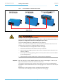
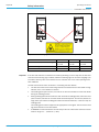
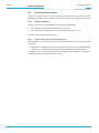
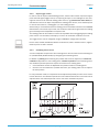
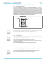
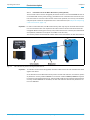
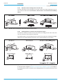
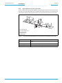
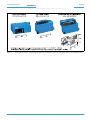
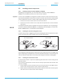
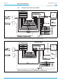
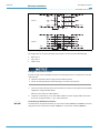
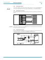
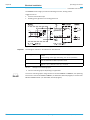
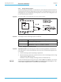
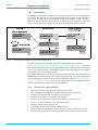
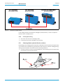
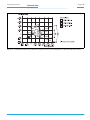
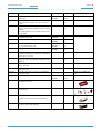
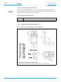
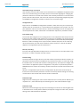
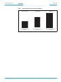
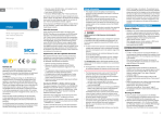
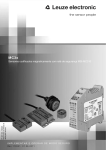
Electrical installation
Chapter 6
Operating Instructions
CLV63x Bar Code Scanner
6.4
Important
Performing electrical installation
To ensure secure fastening of the connected connectors and adherence to the enclosure
rating, the knurled nuts/coupling rings of the M12 connectors have to be tightened or the
cable connectors have to be secured.
1.
Connect or release current linkages only under de-energised conditions.
2.
All wire cross sections and their shields on customer side have to be selected and implemented according to valid engineering standards.
Damage to the connector unit at the bar code scanner due to overwinding.
The connector unit at the bar code scanner has two end positions.
¾
Never turn the connector unit more than 180° in one direction (comming from one of
the end positions).
¾
Always rotate the connector unit in the direction of the laser diode name.
Fig. 6-3:
6.4.1
Direction of rotation of the connector unit
Connecting the power supply for the bar code scanner
The bar code scanner requires a supply voltage of 18 ... 30 V DC (functional extra-low voltage in accordance with IEC 364-4-41 (VDE 0100 (Part 410)) for operation. The functional
extra-low voltage can be created using a safety transformer in accordance with IEC 742
(VDE 0551). The maximum current consumption is 6 W.
The bar code scanner is supplied with 18 ...30 V DC via connection module CDB620 or
CDM420. If the power supply module CMP400/CMP490 is used, the input voltage is 100
... 250 V AC/ 50 ... 60 Hz at the module.
Important
54
The output circuit must be electrically separated from the input circuit. This is usually created by means of a safety transformer in accordance with IEC 742 (VDE 0551).
© SICK AG · Division Auto Ident · Germany · All rights reserved
8011970/S345/2008-04-16