Download Code Code Reader 1000 Operating instructions
Transcript
Operating Instructions O P E R AT I N G I N S T R U C T I O N S CLV63x Bar Code Scanner CLV63x Bar Code Scanner Advanced Line Software Versions Operating Instructions CLV63x Bar Code Scanner Software Versions Software/Tool Function Version CLV63x Bar Code Scanner SICK firmware From v 1.0 0000 Device Description CLV63x Device-specific software module for SOPAS-ET config- From v 2.5 uration software SOPAS-ET Configuration software From v 2.16 Copyright Copyright © 2008 SICK AG Waldkirch Auto Ident, Reute Plant Nimburger Strasse 11 79276 Reute Germany Trademark Windows 2000TM, XPTM, VistaTM and Internet ExplorerTM are registered trademarks or trademarks of the Microsoft Corporation in the USA and other countries. AcrobatTM ReaderTM is a trademark of Adobe Systems Incorporated. Latest manual version For the latest version of this manual (PDF), see www.sick.com. 2 © SICK AG · Division Auto Ident · Germany · All rights reserved 8011970/S345/2008-04-16 Operating Instructions Contents CLV63x Bar Code Scanner Table of contents 1 2 3 4 5 6 7 8 8011970/S345/2008-04-16 Figures and Tables............................................................................................................ 5 Abbreviations..................................................................................................... 5 Tables................................................................................................................. 6 Figures ............................................................................................................... 7 Notes on this document................................................................................................... 9 1.1 Purpose.............................................................................................................. 9 1.2 Target group ...................................................................................................... 9 1.3 Depth of information......................................................................................... 9 1.4 Used symbols ..................................................................................................10 Safety information ..........................................................................................................11 2.1 Authorised users .............................................................................................11 2.2 Intended use ...................................................................................................12 2.3 General safety precautions and protection measures .................................12 2.4 Quick stop and quick restart ..........................................................................15 2.5 Environmental information.............................................................................16 Quick-Start .......................................................................................................................17 3.1 Preparing the bar code scanner for the quick start......................................17 3.2 Establishing connection with the bar code scanner.....................................17 3.3 Performing the reading...................................................................................18 Product description.........................................................................................................21 4.1 Setting up the bar code scanner....................................................................21 4.2 Included in delivery .........................................................................................24 4.3 Device versions ...............................................................................................25 4.4 System requirements......................................................................................26 4.5 Product features and functions (overview) ...................................................26 4.6 Bar code scanner methods of operation.......................................................27 4.7 Indicators and control elements ....................................................................33 Installation .......................................................................................................................39 5.1 Overview of installation sequences ...............................................................39 5.2 Installation preparations ................................................................................39 5.3 Installation location ........................................................................................41 5.4 Installation of the bar code scanner..............................................................46 5.5 Installing external components......................................................................47 5.6 Removing the bar code scanner ....................................................................48 Electrical installation ......................................................................................................49 6.1 Overview of installation sequence .................................................................49 6.2 Electrical installation preparation ..................................................................49 6.3 Electrical connections and cables .................................................................50 6.4 Performing electrical installation ...................................................................54 6.5 Pin assignment and wire colour assignment of the assembled cables ......60 Startup and configuration..............................................................................................63 7.1 Overview of the startup procedure ................................................................63 7.2 SOPAS-ET configuration software ..................................................................63 7.3 Establish communication with the bar code scanner ..................................64 7.4 First startup .....................................................................................................66 7.5 Default setting.................................................................................................68 7.6 Adjusting the bar code scanner .....................................................................69 Maintenance ....................................................................................................................71 8.1 Maintenance during operation.......................................................................71 8.2 Cleaning the bar code scanner ......................................................................71 8.3 Cleaning further optical effective surfaces ...................................................73 8.4 Checking the incremental encoder................................................................74 8.5 Replacing a bar code scanner........................................................................74 © SICK AG · Division Auto Ident · Germany · All rights reserved 3 Contents Operating Instructions CLV63x Bar Code Scanner 9 Troubleshooting .............................................................................................................. 75 9.1 Overview of errors and malfunctions which could occur ............................. 75 9.2 Detailed malfunction analysis ....................................................................... 75 9.3 Status protocol................................................................................................ 76 9.4 SICK Support................................................................................................... 76 10 Technical data................................................................................................................. 77 10.1 Datenblatt Barcodescanner CLV63x (Linien-/Rasterscanner).................... 77 10.2 Data sheet for the CLV63x Bar Code Scanner (line scanner with oscillating mirror)79 10.3 Specification diagrams................................................................................... 80 10.4 CLV63x Bar Code Scanner dimensional drawings ....................................... 90 11 Appendix .......................................................................................................................... 97 11.1 Appendix overview .......................................................................................... 97 11.2 Configuring the bar code scanner with command strings ........................... 97 11.3 Calculating the code length of a bar code .................................................... 98 11.4 Ordering information for bar code scanner and accessories ...................... 99 11.5 Dimensional drawing accessories...............................................................106 11.6 Supplementary documentation ...................................................................110 11.7 Glossary.........................................................................................................111 11.8 EC Declaration of Conformity.......................................................................118 11.9 Code samples of bar codes (selection).......................................................119 4 © SICK AG · Division Auto Ident · Germany · All rights reserved 8011970/S345/2008-04-16 Figures and Tables Operating Instructions Chapter CLV63x Bar Code Scanner Figures and Tables Abbreviations CAN Controlled Area Network (field bus protocol based on the CAN bus) CDB Connection Device Basic CDM Connection Device Modular CLV CMC Code-Leser V-Prinzip Connection Module Cloning CMD Connection Module Device CMF Connection Module Fieldbus CMP Connection Module Power DOF Depth Of Field HTML I Hyper Text Markup Language Input LED Light Emitting Diode MAC Medium Access Control MTBF Mean Time Between Failure MTTR Mean Time To Repair O PROM Output Programable Read Only Memory. RAM Random Acces Memory ROM Read Only Memory RTF SD SMART SOPAS-ET PLC TCP/IP 8011970/S345/2008-04-16 Rich Text Format (standardised document format with format description) Secure Digital SICK Modular Advanced Recognition Technology SICK Open Portal for Application and Systems Engineering Tool (PC software for Windows for configuring the bar code scanner) Programmable Logic Controller Transmission Control Protocol/Internet Protocol © SICK AG · Division Auto Ident · Germany · All rights reserved 5 Chapter Figures and Tables Operating Instructions CLV63x Bar Code Scanner Tables Tab. 1-1: Tab. 2-1: Tab. 2-2: Tab. 4-1: Tab. 4-2: Tab. 4-3: Tab. 4-4: Tab. 4-5: Tab. 4-6: Tab. 5-1: Tab. 6-1: Target group ........................................................................................................9 Required qualification for starting up the bar code scanner ........................ 11 Laser Data of CLV63x ...................................................................................... 14 CLV63x Bar Code Scanner delivery ................................................................ 24 Variants of the CLV63x Bar Code Scanner .................................................... 25 Overview of the bar code scanner's product features and functions ........... 27 Data interface function .................................................................................... 32 LED indications ................................................................................................. 34 Meaning of the LEDs during activation of buttons ......................................... 35 Permitted reading angles between the scanning line and bar code ............ 43 Electrical connections to the bar code scanner with a fixed cable and connector (standard version) .......................................................................... 51 Tab. 6-2: Electrical connections to the bar code scanner with connector unit (Ethernet version) ............................................................................................ 51 Tab. 6-3: Standard version: Pin assignment of the 15-pole D-Sub-HD cable onnector ........................................................................................................... 52 Tab. 6-4: Ethernet version: Pin assignment of the 4-pole M12 socket ....................... 52 Tab. 6-5: Ethernet version: Pin assignment on the 12-pole M12 plug ........................ 53 Tab. 6-6: Recommended maximum cable lengths, depending on the selected data transfer rate ............................................................................................. 55 Tab. 6-7: Ratings for the switching inputs ..................................................................... 58 Tab. 6-8: Ratings for the switching outputs ................................................................... 59 Tab. 6-9: Pin assignment of the 4-pole M12 plug and the 6-pole RJ45 plug .............. 60 Tab. 6-10: Pin assignment of the 12-pole M12 socket and the 15-pole D-Sub-HD plug .................................................................................................. 60 Tab. 6-11: Pin assignment of the 12-pole M12 socket and wire colours at the open end ........................................................................................................... 61 Tab. 6-12: Pin assignment of the 5-pole M12 plug and wire colours at the open end ........................................................................................................... 61 Tab. 6-13: Pin assignment of the 15-pole D-Sub-HD socket and wire colours at the open cable end ...................................................................................... 62 Tab. 7-1: Default setting for the SOPAS-ET configuration software (excerpt) ............. 64 Tab. 7-2: Connection between the PC with SOPAS-ET configuration software and the bar code scanner ............................................................................... 64 Tab. 10-1: Technical specifications for the CLV63x Bar Code Scanner (line/raster scanner)......................................................................................... 78 Tab. 10-2: Technical specifications for the CLV63x Bar Code Scanner (line scanner with oscillating mirror) ............................................................... 79 Tab. 10-3: Reading conditions for all specification diagrams ........................................ 80 Tab. 11-1: Help table for calculating the code length of a bar code ............................... 98 Tab. 11-2: Variants of the CLV63x Bar Code Scanner .................................................... 99 Tab. 11-3: In stock accessories: Installation accessories..............................................100 Tab. 11-4: In stock accessories: Connection modules................................................... 101 Tab. 11-5: In stock accessories: Extensions for connection modules ..........................103 Tab. 11-6: In stock accessories: Separate field bus modules ....................................... 103 Tab. 11-7: In stock accessories: Cables and connectors for the standard version of the bar code scanner ................................................................................. 104 Tab. 11-8: In stock accessories: Cables and connectors for the Ethernet version of the bar code scanner ................................................................................. 104 Tab. 11-9: In stock accessories: General cables and connectors for bar code scanner................................................................................................... 105 Tab. 11-10: In stock accessories: Memory media for CLV63x Bar Code Scanner ........ 106 Tab. 11-11: Supplementary documentation .....................................................................110 6 © SICK AG · Division Auto Ident · Germany · All rights reserved 8011970/S345/2008-04-16 Operating Instructions Figures and Tables Chapter CLV63x Bar Code Scanner Figures Fig. 2-1: Fig. 2-2: Fig. 3-1: Fig. 4-1: Fig. 4-2: Fig. 4-3: Fig. 4-4: Fig. 4-5: Fig. 4-6: Fig. 5-1: Fig. 5-2: Fig. 5-3: Fig. 5-4: Fig. 5-5: Fig. 5-6: Fig. 5-7: Fig. 5-8: Fig. 6-1: Fig. 6-2: Fig. 6-3: Fig. 6-4: Fig. 6-5: Fig. 6-6: Fig. 6-7: Fig. 6-8: Fig. 7-1: Fig. 8-1: Fig. 8-2: Fig. 10-1: Fig. 10-2: Fig. 10-3: Fig. 10-4: Fig. 10-5: Fig. 10-6: 8011970/S345/2008-04-16 Outlet opening of the laser radiation at the reading window (shown here: Ethernet version)........................................................................ 13 Laser warning sign attached to the bar code scanner at delivery ................ 14 Register tab Quickstart .................................................................................... 18 Housing types of the CLV63x Bar Code Scanner............................................ 22 Device view of the CLV63x Bar Code Scanner (shown here: Ethernet-Version)........................................................................ 23 Bar code scanner's methods of operation in a conveyor system (schematic)........................................................................................................ 28 CLV63x Oscillating Mirror: Example of focal position control in search run, here with 6 focus positions ......................................................... 29 Reading operation mode for the CLV63x Bar Code Scanner in stand-alone operation .................................................................................... 31 Micro SD memory card for storing the parameter set.................................... 37 Example: Fixing the bar code scanner with the bracket no. 2042800 ........ 40 Exchanging the laser warning sign ................................................................. 41 Allocation of the scanning line(s) for the bar code and conveyor system .... 42 Definition of the reading distance a and the aperture angle α ..................... 42 Line scanner: Reading angles that occurs between the scanning line and bar code ............................................................................................. 43 Avoiding surface reflection using the line scanner as an example: Angle between emitting light and bar code (tilted away from the plumb line) ..................................................................... 44 Counting direction of the reading angle RA within the scanning line and of the code angle CW with the oscillating mirror..................................... 45 Line scanner: Installation example for positioning the external reading pulse sensor ....................................................................................... 47 Standard version: Electrical connections at the bar code scanner with connection cable....................................................................................... 50 Ethernet version: Electrical connections at the bar code scanner with connector unit ........................................................................................... 50 Direction of rotation of the connector unit ..................................................... 54 Wiring the serial host data interfaces (RS-232 or RS-422) on the 15-pole D-Sub-HD plug .................................................................................... 56 Function of the Ethernet interface .................................................................. 57 Wiring the “Sensor 1“ switching input on the 15-pole D-Sub-HD plug ......... 57 Wiring the "Sensor 2" switching input on the 15-pole D-Sub-HD plug ......... 58 Possible wiring of the "Result 1" switching output on the 15-pole D-Sub-HD plug .................................................................................................. 59 Configuration with SOPAS-ET and storage the parameter set....................... 66 Cleaning the reading window ........................................................................... 73 Cleaning of the external optical sensors (reading pulse generator) ............ 73 CLV630: Reading ranges of the line scanner/raster scanner with front reading window ........................................................................................ 80 CLV630: Reading ranges of the line scanner/raster scanner with side reading window ......................................................................................... 81 CLV630: Reading ranges of the line scanner with oscillating mirror (side reading window)....................................................................................... 81 CLV630: Set of characteristic curves for scan frequency, depending on the reading distance and resolution (line scanner/raster scanner with front reading window) ............................................................................... 82 CLV631: Reading ranges of the line scanner/raster scanner with front reading window ........................................................................................ 83 CLV631: Reading ranges of the line scanner/raster scanner with side reading window ......................................................................................... 83 © SICK AG · Division Auto Ident · Germany · All rights reserved 7 Chapter Figures and Tables Operating Instructions CLV63x Bar Code Scanner Fig. 10-7: Fig. 10-8: Fig. 10-9: Fig. 10-10: Fig. 10-11: Fig. 10-12: Fig. 10-13: Fig. 10-14: Fig. 10-15: Fig. 10-16: Fig. 10-17: Fig. 10-18: Fig. 10-19: Fig. 10-20: Fig. 10-21: Fig. 11-1: Fig. 11-2: Fig. 11-3: Fig. 11-4: Fig. 11-5: Fig. 11-6: 8 CLV631: Reading ranges of the line scanner with oscillating mirror (side reading window)....................................................................................... 84 CLV631: Set of characteristic curves for scan frequency, depending on the reading distance and resolution (line scanner/raster scanner with front reading window)....................................................................................... 84 CLV632: Reading ranges of the line scanner/raster scanner with front reading window ........................................................................................ 85 CLV632: Reading ranges of the line scanner/raster scanner with side reading window ......................................................................................... 86 CLV632: Reading ranges of the line scanner with oscillating mirror (side reading window)....................................................................................... 87 CLV632: Set of characteristic curves for scan frequency, depending on the reading distance and resolution (line scanner/raster scanner with front reading window) ............................................................................... 87 CLV630-6000/CLV630-6120: Deflection range as a function of the reading distance, deflection angle and resolution ......................................... 88 CLV631-6000/CLV631-6120: Deflection range as a function of the reading distance, deflection angle and resolution ......................................... 88 CLV632-6000/CLV632-6120: Deflection range as a function of the reading distance, deflection angle and resolution ......................................... 89 Standard version: Dimensions of the bar code scanner with front reading window (CLV63x-0000 and CLV63x-1000)....................................... 90 Standard version: Dimensions of the bar code scanner with side reading window (CLV63x-2000 and CLV63x-3000)....................................... 91 Standard version: Dimensions of the bar code scanner with oscilliating mirror (CLV63x-6000)....................................................................................... 92 Ethernet version: Dimensions of the bar code scanner with front reading window (CLV63x-0120 and CLV63x-1120)....................................... 93 Ethernet version: Dimensions of the bar code scanner with side reading window (CLV63x-2120 and CLV63x-3120)....................................... 94 Ethernet version: Dimensions of the bar code scanner with oscilliating mirror (CLV63x-6120)....................................................................................... 95 Dimensions of the fixing bracket no. 2020410 .......................................... 106 Dimensions of the quick release clamp no. 2025526 ............................... 107 Dimensions of the fixing bracket no. 2042800 ...........................................108 Dimensions of the round rod holder no. 2042801 ......................................109 EC Declaration of Conformity for the bar code scanner (page 1, scaled down version) ...................................................................... 118 Code samples of bar codes of various module widths (print ratio 2:1) ..... 119 © SICK AG · Division Auto Ident · Germany · All rights reserved 8011970/S345/2008-04-16 Operating Instructions Notes on this document Chapter 1 CLV63x Bar Code Scanner 1 Notes on this document 1.1 Purpose This document provides instructions for technical staff on the installation and operation of the bar code scanner series CLV63x with fixed focus in the following versions: • Line scanner / raster scanner / line scanner with oscillating mirror • Mid-range / short-range / long-range reading area • With front / side reading window • With cable and connector (standard version) / with connector unit (Ethernet version) A summary of all device versions is shown in chapter 4.3 Device versions, page 25. This document contains the following information: • Installation • Electrical installation • Startup and configuration • Maintenance • Troubleshooting • Replacing the bar code scanner A step-by-step approach is taken for all tasks. 1.2 Target group The target group of this document is persons assigned the following tasks: Tasks Target group Installation, electrical installation, maintenance, Qualified staff, e.g. service technicians and facreplacing the device tory electricians Startup and configuration Trained staff, e.g. technicians or engineers Operation of the conveyor system Qualified staff for start-up and operation of the conveyor system Tab. 1-1: 1.3 Target group Depth of information This document contains all the required information for installation, electrical installation and operation of the bar code scanner at the installation location. The factory default setting (basic configuration) of the bar code scanner is prepared for the use as a stand-alone device. Configuration of the bar code scanner for the application-specific reading conditions and operation is carried out using the SOPAS-ET configuration software on a WindowsTM PC. The SOPAS-ET configuration software contains an online help system to facilitate configuration. Important Further information about the design of the bar code scanner as well as the bar code technology is available from SICK AG, Auto Ident division. On the Internet at www.sick.com. 8011970/S345/2008-04-16 © SICK AG · Division Auto Ident · Germany · All rights reserved 9 Notes on this document Chapter 1 Operating Instructions CLV63x Bar Code Scanner 1.4 Used symbols To gain easier access, some information in this documentation is emphasised as follows: Notice! ¾ Indicates a potential risk of damage or impair on the functionality of the bar code scanner or other devices. Warning notice! A warning notice indicates real or potential danger. This should protect you against accidents. The safety symbol next to the warning notice indicates why there is a risk of accident, e.g. due to electricity. The warning levels (DANGER, WARNING, CAUTION) indicate the seriousness of the risk. ¾ Carefully read and follow the warning notices! Reference Italic script denotes a reference to further information. Important This important note informs you about specific features. Explanation Recommendation TIP PROJECT An explanation provides background knowledge of technical nature. A recommendation helps you to carry out tasks correctly. A tip explains setting options in the SOPAS-ET configuration software. This type of script denotes a term in the user interface in the SOPAS-ET configuration software. A symbol indicates a button in the user interface of the SOPAS-ET configuration software. There is a procedure which needs to be carried out. This symbol indicates operational instructions which only contain one operational step or operational steps in warning notices which do not have to be followed in any particular order. Operational instructions comprising several steps are denoted using consecutive numbers. This symbol indicates a reference to other information in the glossary. Note This symbol denotes a section in which the operation steps with the SOPAS-ET configuration software are described. Important This symbol indicates supplementary technical documentation. 10 © SICK AG · Division Auto Ident · Germany · All rights reserved 8011970/S345/2008-04-16 Operating Instructions Safety information Chapter 2 CLV63x Bar Code Scanner 2 Safety information This chapter deals with your safety and operator safety in the operational area. ¾ Read this chapter carefully before using the bar code scanner. 2.1 Authorised users For correct and safe functioning, the bar code scanner must be installed, operated and maintained by sufficiently qualified staff. Repairs to the bar code scanner should only be carried out by qualified and authorised SICK AG service staff. ¾ The operating instructions should be made available to the end user. ¾ The end user should be briefed and urged to read the operating instructions by the technicians. The following qualifications are required for different activities: Tasks Qualification Installation, maintenance • Practical technical training • Knowledge of current health and safety regulations at the workplace Electrical installation, device • Practical electrical training replacement • Knowledge of current electrical safety regulations • Knowledge of start-up and operation of the device in each operational area (e. g. conveyor system) Startup, configuration • Basic knowledge of the WindowsTM operating system • Basic knowledge of designing and setting up (addressing) Ethernet connections for connecting the bar code system to the Ethernet • Basic knowledge of working with an HTML browser (e. g. Internet ExplorerTM) for using the online help • Basic knowledge of data transfer • Basic knowledge of bar code technology Operation of the device in each operational area • Knowledge of start-up and operation of the device in each operational area (e. g. conveyor system) • Knowledge of the software and hardware environment in each operational area (e. g. conveyor system) Tab. 2-1: 8011970/S345/2008-04-16 Required qualification for starting up the bar code scanner © SICK AG · Division Auto Ident · Germany · All rights reserved 11 Safety information Chapter 2 Operating Instructions CLV63x Bar Code Scanner 2.2 Intended use The CLV63x Bar Code Scanner is an intelligent sensor for the automatic recognition and decoding of bar codes on objects e.g. in a conveyor system. The intended use of the bar code system results from the following description of the function: Important • In a reading station, the bar code scanner is installed in a holder, either on the side of a conveyor system (side reading) or above it (reading from above). • The bar code scanner transfers the reading data via the host interface to a superordinate host computer for further processing. • The bar code scanner is configured/operated using the SOPAS-ET configuration software that runs on a standard client PC provided by the customer. Communication takes place using RS-232 or Ethernet. Any warranty claims against SICK AG shall be deemed invalid in the case changes to the bar code scanner, such as opening the housing, this includes modifications during installation and electrical installation or changes to the SICK software. The bar code scanner is only to be operated in ambient air temperature limit. 2.3 ¾ General safety precautions and protection measures Read the general safety precautions thoroughly and observe them during all bar code scanner activities. Also observe the warning notices above the operational instructions of each chapter. 2.3.1 Electrical installation work Risk of injuries due to electrical current! The optional power supply module CMP400/CMP490 is connected to the power supply (100 ... 250 V AC/50 ... 60 Hz) in connection module CDM420. ¾ Important Observe current safety regulations when working with electrical equipment. Electrical installation should only be carried out by qualified staff. Connect or release current linkages only under de-energised conditions. Wire cross sections and their correct shields have to be selected and implemented according to valid engineering standards. 12 © SICK AG · Division Auto Ident · Germany · All rights reserved 8011970/S345/2008-04-16 Operating Instructions Safety information Chapter 2 CLV63x Bar Code Scanner 2.3.2 Fig. 2-1: Laser radiation of the bar code scanner Outlet opening of the laser radiation at the reading window (shown here: Ethernet version) Damage to the eyes through laser radiation! The bar code scanner operates with an red light laser of class 2. Looking at the laser's light path for a longer period of time can damage the eye's retina. The entire reading window is the LED radiation outlet opening. Caution - use of controls or adjustments or performance of procedures other than those specified herein may result in hazardous radiation exposure. Important ¾ Never look directly into the light path (similar to sun light). ¾ Never direct the device's laser beam at the eyes of persons. ¾ When installing and aligning the bar code scanner, avoid laser beam reflections from reflective surfaces. ¾ Do not open the housing. (Opening does not interrupt the activation of the laser diode by the reading pulsing.) ¾ Always observe the latest valid version of laser protection regulations. Bar code scanners in series CLV63x operate with a laser of wavelength λ = 655 nm (red light). The radiation emitted is not harmful to human skin. The product is classified in laser class 2 (laser class II) in accordance with EN 60825-1, IEC 60825-1 and 21 CFR 1040.10 (see the warning sign on the device for the date of publication) Maintenance is not required to ensure compliance with laser class 2. The bar code scanner displays a black and yellow laser warning sign. 8011970/S345/2008-04-16 © SICK AG · Division Auto Ident · Germany · All rights reserved 13 Safety information Chapter 2 Operating Instructions CLV63x Bar Code Scanner Standard version Fig. 2-2: Laser warning sign attached to the bar code scanner at delivery Device CLV630 CLV631 CLV632 Laser out radiation (maximum/average) 3.2 mW/ <1.0 mW 3.2 mW/ <1.0 mW 3.2 mW/ <1.0 mW Emitted wavelength 655 nm 655 nm 655 nm Pulse duration < 300 μs < 300 μs < 300 μs Tab. 2-2: Important Ethernet version Laser Data of CLV63x If the bar code scanner is installed in a machine/panelling in such a way that the bar code scanner's laser warning sign is hidden, additional warning signs in the same language (not included in delivery) have to be attached to the machine next to the outlet opening of the laser radiation! The bar code scanner works as follows in controlling the laser diodes: • The bar code scanner has monitoring switches that deactivate the laser diode if irregularities occur in the radiation emission. • The reading pulse (pulse source) controls the on and off mechanism of the laser diode during the reading process. • During reading operation with "Sensor" and "Command" reading pulses, each time level (laser timeout) switches off the laser diode automatically after 10 minutes (default settings) when a permanent reading pulse has been started. However, it does not stop the reading pulse. The reading pulse can be stopped via an appropriate clock signal. The successive reading pulse switches on the laser diode. • 14 In SOPAS-ET on the "Illumination control" tab you can set or deactivate the laser timeout within a range of 1 ... 1,500 min (= 25h). © SICK AG · Division Auto Ident · Germany · All rights reserved 8011970/S345/2008-04-16 Operating Instructions Safety information Chapter 2 CLV63x Bar Code Scanner • "Laser" LED: During normal reading operation the "Laser" LED lights up when the laser diode is switched on. When calling up functions via the two buttons of the bar code scanner (aborting normal reading operation), the LEDs have got additional display functions. The "Laser" LED will differ from its original function. It is possible that the "Laser" LED is flashing when Autosetup is selected, although the laser diode is still switched off or the laser diode is switched on, for example, in diagnostic mode (Read Diagn) and the "Laser" LED, however, is not flashing. 2.4 Quick stop and quick restart The bar code scanner can be switched on or off using the main switch for connection modules CDB620 or CDM420. 2.4.1 ¾ Switching off the bar code scanner Switch off the power supply to the bar code scanner (the connection module) - or Remove (pull out) the 15-pole D-Sub-HD connector of the bar code scanner's connection cable from the connection module. When the bar code scanner is switched off, the following data is lost: • Application-specific parameter sets in the bar code scanner that were only saved temporarily in the device • The last reading result of the bar code scanner • Daily operating hours counter of the bar code scanner 2.4.2 ¾ Switching the bar code scanner back on Switch the power supply to the bar code scanner (the connection module) back on - or Connect the 15-pole D-Sub-HD connector of the bar code scanner's connection cable to the connection module. The bar code scanner starts up using the most recent permanently saved configuration. The daily operating hours counter is reset. 8011970/S345/2008-04-16 © SICK AG · Division Auto Ident · Germany · All rights reserved 15 Chapter 2 Safety information Operating Instructions CLV63x Bar Code Scanner 2.5 Environmental information The bar code scanner has been constructed with minimum environmental pollution in mind. Excluding the housing, the bar code scanner does not contain any materials using silicone. 2.5.1 Energy requirements The bar code scanner series CLV63x consumes the following energy: • Line / Raster scanner: Typically 5 W with 24 V DC ± 10 % • Line scanner with oscillating mirror: Typically 6 W with 24 V DC ± 10 % All values with unwired switching outputs. 2.5.2 Dispose of the device after decommissioning SICK AG will not currently accept the return of any devices which can no longer be operated or repaired. ¾ Inoperable or irreparable devices must be disposed of in an environmentally friendly manner and in accordance with valid country-specific waste disposal guidelines. The design of the bar code scanner allows for its separation as recyclable secondary raw materials and hazardous waste (electronic scrap). 16 © SICK AG · Division Auto Ident · Germany · All rights reserved 8011970/S345/2008-04-16 Quick-Start Operating Instructions Chapter 3 CLV63x Bar Code Scanner 3 Quick-Start 3.1 Preparing the bar code scanner for the quick start The bar code scanner can be operated quickly and easily using the supplied SOPAS-ET configuration software. The software offers the following options, among others: • Fast connection with the bar code scanner • Configuration of the most important reading parameters and display of the reading results on one clear register tab in the configuration software System requirements for using the SOPAS-ET configuration software See chapter 7.2.2 System requirements for the SOPAS-ET configuration software, page 63. Additional accessories required (not in delivery) • Connection module CDB620 or CDM420 • For the Ethernet version of the bar code scanner: Connection cable for data and function interfaces (see chapter 11.4.7 Accessories: Cables for Ethernet version, page 104) • 3-wire RS-232 data cable (null modem cable no. 2014054) - or To connect an Ethernet version of the bar code scanner to the PC's Ethernet interface: relevant cable (see chapter 11.4.7 Accessories: Cables for Ethernet version, page 104). Perform an electrical connection to the bar code scanner 1. Connect the bar code scanner to connection module CDB620/CDM420. 2. Switch on the power supply for CDB620/CDM420. 3. Switch on the PC for the configuration and install and start the supplied SOPAS-ET configuration software. 4. Connect the bar code scanner. To achieve this, connect the PC using a 3-wire RS-232 data cable (null modem cable) to the "Aux“ connection in CDB620/CDM420. - or Connect the PC to the bar code scanner's Ethernet interface (Ethernet version). For detailed instructions, see chapter 5 Installation, page 39 and chapter 6 Electrical installation, page 49. 3.2 ¾ TIP 8011970/S345/2008-04-16 Establishing connection with the bar code scanner Communicate with the bar code scanner according to the selected data interface (RS232 or Ethernet) (see chapter 7.3 Establish communication with the bar code scanner, page 64) and perform a scan. To establish a connection quickly and easily via Ethernet, the SOPAS-ET configuration software has a CONNECTION WIZARD in the TOOLS menu. © SICK AG · Division Auto Ident · Germany · All rights reserved 17 Chapter 3 Quick-Start Operating Instructions CLV63x Bar Code Scanner 3.3 Performing the reading Note With the SOPAS-ET configuration software, the QUICKSTART register tab contains the most important reading parameters for configuring and performing a bar code reading: PROJECT TREE, CLV63X, QUICKSTART register tab Fig. 3-1: Register tab Quickstart Perform the reading: 1. Ensure that the relevant code types are activated on the register tab. 2. Carry out a test reading with a test bar code. To achieve this, hold an object with a bar code in front of the bar code scanner's reading window and trigger the reading by clicking START. The default setting of the focus position is 285 mm (11.2 in). If necessary, observe the bar code scanner's depth of fields ranges in relation to the resolution (see chapter 10.3 Specification diagrams, page 80). During reading operation and with default settings, the line scanner with oscillating mirror deflects the scanning line by the central position with a frequency of 1 Hz and at a max. angle of ± 20°. The reading result is displayed in the BARCODE CONTENT display field. The code reading reliability is specified in the relevant display field. 18 © SICK AG · Division Auto Ident · Germany · All rights reserved 8011970/S345/2008-04-16 Operating Instructions Quick-Start Chapter 3 CLV63x Bar Code Scanner Optimise the reading conditions: If no reading result is displayed or if you wish to increase the code reading reliability, the reading can be repeated by taking the following measures. 8011970/S345/2008-04-16 ¾ Install the bar code scanner in such a way that the bar code scanner's light meets the idle object (code) at a 15° angle (skew). ¾ Correct or optimise the parameter values where necessary via the SOPAS-ET configuration software. © SICK AG · Division Auto Ident · Germany · All rights reserved 19 Chapter 3 Quick-Start Operating Instructions CLV63x Bar Code Scanner 20 © SICK AG · Division Auto Ident · Germany · All rights reserved 8011970/S345/2008-04-16 Operating Instructions Product description Chapter 4 CLV63x Bar Code Scanner 4 Product description This chapter describes the design, the features and the functions of the CLV63x Bar Code Scanner. ¾ 4.1 For installation, electrical installation and startup assistance as well as for the application-specific configuration of the bar code scanner using the SOPAS-ET configuration software, please read this chapter prior to carrying out any of the tasks. Setting up the bar code scanner The CLV63x Bar Code Scanner consists of a laser scanner (laser diode and lens) with fixed focus and an electronic unit with an integrated decoder. The laser scanner and electronic unit are located in a housing. The ligh exits and enters via a reading window in the industrialtype housing. The bar code scanner (depending on the version) is electrically connected by a cable with a connector or a revolving connector unit with two connections. For an adaption to on-site space conditions/reading functions three housings are available: a housing with front reading window, a housing with side reading window and a housing with oscillating mirror. Via the integrated angle attachment/oscillating mirror, the laser beam exits through the side reading window at an angle of emergence of 105°. For the oscillating mirror this corresponds to the central position (default settings) of the laser beam perpendicular to the scan direction. Depending on the type, various lenses enable different resolutions and reading areas. 8011970/S345/2008-04-16 © SICK AG · Division Auto Ident · Germany · All rights reserved 21 Chapter 4 Product description Operating Instructions CLV63x Bar Code Scanner 4.1.1 Fig. 4-1: 22 Device view Housing types of the CLV63x Bar Code Scanner © SICK AG · Division Auto Ident · Germany · All rights reserved 8011970/S345/2008-04-16 Operating Instructions Product description Chapter 4 CLV63x Bar Code Scanner Fig. 4-2: Device view of the CLV63x Bar Code Scanner (shown here: Ethernet-Version) 8011970/S345/2008-04-16 © SICK AG · Division Auto Ident · Germany · All rights reserved 23 Product description Chapter 4 Operating Instructions CLV63x Bar Code Scanner 4.2 Included in delivery Delivery of the CLV63x Bar Code Scanner includes the following components: Piece(s) Components Comment 1 Bar code scanner CLV630 / CLV631 / CLV632 depending on version 1 Set of laser warning signs for class 2 in German/American English and French/ American English Self-adhesive to affix the warning sign to the bar code scanner's housing (if necessary) 1 Notes on device with electrical connection diagram as primary information Included in the device packaging of the CLV63x Bar Code Scanner 1 CD-ROM "Manuals & Software Auto Ident" CLV63x Operating Instructions in printed Optional, depending on the number of form, in German and/or English issues explicitly ordered upon purchase Tab. 4-1: Important CLV63x Bar Code Scanner delivery The Micro-SD memory card is not included in delivery. An overview of in-stock installation accessories, connection modules, cables and connectors, sensors for reading pulses as well as memory media is available in chapter 11.4 Ordering information for bar code scanner and accessories, page 99. Important For save operation of the Micro-SD memory card, use only SICK approved memory card. 4.2.1 Important 24 Contents of the CD-ROM • "SOPAS-ET Engineering Tool“: Configuration software for WindowsTM PCs with integrated online help system (HTML files) • CLV63x operating instructions: PDF version in German and English as well as further publications of other SICK devices • “Acrobat Reader“: Freely available PC software for reading PDF files The current versions of publications and programs on the CD-ROM can also be downloaded at www.sick.com. © SICK AG · Division Auto Ident · Germany · All rights reserved 8011970/S345/2008-04-16 Operating Instructions Product description Chapter 4 CLV63x Bar Code Scanner 4.3 Device versions The CLV63x Bar Code Scanner with a glass reading window is available in the following versions, among others: Order no. Type Scanning method Reading window Connection (design) CLV630: Long-range reading range 1040706 CLV630-0000 Line scanner On front Cable with connector 1041969 CLV630-0120 Line scanner On front Connector unit on device 1041970 CLV630-1000 Raster scanner On front Cable with connector 1041971 CLV630-1120 Raster scanner On front Connector unit on device 1041972 CLV630-2000 Line scanner On side Cable with connector 1041973 CLV630-2120 Line scanner On side Connector unit on device 1041974 CLV630-3000 Raster scanner On side Cable with connector 1041975 CLV630-3120 Raster scanner On side Connector unit on device 1041976 CLV630-6000 Line scanner with On side oscillating mirror Cable with connector 1041977 CLV630-6120 Line scanner with On side oscillating mirror Connector unit on device CLV631: Mid-range reading range 1041978 CLV631-0000 Line scanner On front Cable with connector 1041979 CLV631-0120 Line scanner On front Connector unit on device 1041980 CLV631-1000 Raster scanner On front Cable with connector 1041981 CLV631-1120 Raster scanner On front Connector unit on device 1041982 CLV631-2000 Line scanner On side Cable with connector 1041983 CLV631-2120 Line scanner On side Connector unit on device 1041984 CLV631-3000 Raster scanner On side Cable with connector 1041985 CLV631-3120 Raster scanner On side Connector unit on device 1041986 CLV631-6000 Line scanner with On side oscillating mirror Cable with connector 1041987 CLV631-6120 Line scanner with On side oscillating mirror Connector unit on device CLV622: Short-range reading range 1041988 CLV632-0000 Line scanner On front Cable with connector 1041989 CLV632-0120 Line scanner On front Connector unit on device 1041990 CLV632-1000 Raster scanner On front Cable with connector 1041991 CLV632-1120 Raster scanner On front Connector unit on device 1041992 CLV632-2000 Line scanner On side Cable with connector 1041993 CLV632-2120 Line scanner On side Connector unit on device 1041994 CLV632-3000 Raster scanner On side Cable with connector 1041995 CLV632-3120 Raster scanner On side Connector unit on device 1041996 CLV632-6000 Line scanner with On side oscillating mirror Cable with connector 1041997 CLV632-6120 Line scanner with On side oscillating mirror Connector unit on device Tab. 4-2: 8011970/S345/2008-04-16 Variants of the CLV63x Bar Code Scanner © SICK AG · Division Auto Ident · Germany · All rights reserved 25 Product description Chapter 4 Operating Instructions CLV63x Bar Code Scanner Important Depending on the connection (design), the following interfaces are available: • Standard version (cable with connector) – RS-232, RS-422/485, CAN, two digital switching inputs, two digital switching outputs, power supply • Ethernet version (revolving connector unit) – Connector 1: Ethernet – Connector 2: RS-232, RS-422/485, CAN, one digital switching input, power supply 4.4 System requirements General system requirements are derived from the bar code scanner's technical data (see chapter 10 Technical data, page 77). The requirements and conditions for Installation, Electrical installation and Startup and configuration are summarised in the respective chapters. 4.5 Product features and functions (overview) CLV63x Bar Code Scanner • • • • • • • • Fixed focus Line scanner / raster scanner / line scanner with oscillating mirror Reading window on front / side Large reading area (depending on version) High resolution (depending on version) High scan frequency Can be adapted to the print quality of the code Evaluation area of the scanning line can be restricted User safety and convenience • • • • • • • • • Robust, compact metal housing, CE mark Laser class 2, laser switches off if the output capacity is exceeded Automatic self-test on system startup Diagnosis tools for system setup and system (remote) monitoring Configurable reading diagnosis data display in two reading result formats Operational data retrieval, error code display on request in case of errors Activatable test string function (heartbeat) for signalling readiness for operation Password protected configuration mode Configured parameter values (cloning) can be additionally secured on a Micro SD memory card (can be removed in the case of bar code scanner replacement ) Future proof due to firmware update (flash PROM) via data interface Future-proof SOPAS-ET configuration software Low current consumption Extended power supply range • • • • Convenient operation/configuration • Configuration (online/offline) using the SOPAS-ET configuration software (incl. help system) • 2 buttons on the device for calling up preset functions without connecting a PC • Status indicators via five LEDs • Beeper that can be switched off to confirm device functioning Reading operation modi • Start/Stop operation Reading pulse • Pulse sources for start: switching inputs; data interface (command); automatic cycle; CAN • Pulse sources for stop: reading pulse source, switching inputs, command, timer, condition Bar code evaluation 26 • All common bar code types • Max. number of bar codes: 50 per reading pulse • Separation of identical codes of the same code type using the reading angle © SICK AG · Division Auto Ident · Germany · All rights reserved 8011970/S345/2008-04-16 Operating Instructions Product description Chapter 4 CLV63x Bar Code Scanner • Manipulation of the output of the reading data via event-dependent evaluation condi- Data processing tions • Manipulation of the output strings through filter and output sort options • Host interface: two data output formats configurable, switchable to different physical Data communication interfaces, parallel operation possible • Aux interface: fixed data output format, switchable to different physical interfaces, parallel operation possible • Host interface: RS-232, RS-422/485 (data format and protocol can be configured) and Electrical interfaces Ethernet, or CAN • Aux interface: RS-232, (fixed data format, data transfer rate and protocol) and Ethernet • CAN interface for integration into the SICK-specific CAN-SENSOR network • Digital switching inputs – Standard version: Two digital switching inputs for external reading pulse sensor(s) or incremental encoder, using optocoupler – Ethernet version: One digital switching input on the device • Digital switching outputs – Standard version: Two digital switching outputs for signalling definable results in the reading process (reading result status) – Ethernet version: No digital switching output on the device • Standard version: Cable with 15-pole D-Sub-HD connector • Ethernet version: Revolving connector unit on the device with two M12 circular connec- Connection technology (design) tors • Connection module CDB620/CDM420 for connection to the host computer (standalone) and for integrating into the SICK-specific CAN-SENSOR network • Bus connection module CMF4001) in connection module CDM420 for connecting to field bus systems 1) Supported by SOPAS-ET from Q4 2007 Tab. 4-3: Overview of the bar code scanner's product features and functions 4.6 Bar code scanner methods of operation The CLV63x Bar Code Scanner is an intelligent sensor system for automatic and non-contact detection and decoding of bar codes. In principle, the codes can be detected on any side of still or moving objects in a conveyor system (single-side reading). Several bar code scanners can be combined to allow detection of several sides in one passage (multi-side reading). The bar code scanner creates a scanning line (line scanner) to recognise the codes. In the raster scanner version, the bar code scanner creates eight scanning lines that are moved parallel to each other. Line scanner with oscillating mirror The oscillating mirror additionally deflects the scanning line from the home position to both sides, perpendicular to the scanning direction, with a low oscillation frequency. This enables the bar code scanner to scan larger areas for bar codes as well. The length of the scanning line that is used for the evaluation (reading area height) depends on the reading distance because of the V-shaped light exit. The light pattern that is reflected by the bar code is recorded, processed and decoded. To control this process, external sensors deliver information via the reading pulse, the object distance and the conveyor speed (increment). The reading results are output to the bar code scanner's data interfaces and forwarded to a host/PC. 8011970/S345/2008-04-16 © SICK AG · Division Auto Ident · Germany · All rights reserved 27 Chapter 4 Product description Operating Instructions CLV63x Bar Code Scanner Fig. 4-3: Bar code scanner's methods of operation in a conveyor system (schematic) The detailed wiring of the bar code scanner and the connections to the host/PC and to the external sensors is described in chapter 6 Electrical installation, page 49. 4.6.1 Reading configuration The bar code scanner detects bar codes with an adjustable scan frequency. The bar code scanner can detect codes on still and moving objects. For more rapid evaluation, the reading range of the scanning line (reading angle: RA value) can be restricted. Note The SOPAS-ET configuration software can, among other things, be used to configure the reading angle and the symbol contrast: PROJECT TREE, CLV63X, PARAMETER, READING CONFIGURATION, register tab CODELABEL PROPERTIES 28 © SICK AG · Division Auto Ident · Germany · All rights reserved 8011970/S345/2008-04-16 Operating Instructions Product description Chapter 4 CLV63x Bar Code Scanner 4.6.2 Object trigger control In order to start an object-related reading process, the bar code scanner requires an appropriate external signal (trigger source) for reporting an object in the reading area. The start signal is emitted via an external reading pulse sensor (e. g. photoelectric reflex switch) as standard. As soon as an object has passed the reading pulse sensor, a time window opens in the bar code scanner (“reading gate“) for the reading process. Alternatively, a command activates the reading process via a data interface or the CAN-SENSOR network. In Automatic Cycle mode, the actual bar code scanner generates the reading gate internally with an adjustable mark-space ratio. The reading pulse can be ended in a number of ways: With external triggering by the reading pulse source or a command, internally by a timer or an evaluation condition to be met. Note The trigger source can be configured using the SOPAS-ET configuration software: PROJECT TREE, CLV63X, PARAMETER, READING CONFIGURATION, OBJECT TRIGGER CONTROL, register tab START/STOP OF OBJECT TRIGGER 4.6.3 Oscillating mirror control You can manipulate the position of the scanning line for the line scanner with oscillating mirror (CLV63x-6000/CLV63x-6120) by configuring the oscillating mirror. In addition to parking (fixed scanning line position which can be adjusted) or continuous oscillation independent of the reading pulse, controlled operation of the oscillating mirror also enables optimised operation sequences related to the reading pulse: • n-fold oscillation around an adjustable start position within the reading pulse • One-shot: one-time deflection (forward and return) per reading pulse from an adjustable start position In every oscillation mode, the amplitude can be adjusted separately for each of the two deflection directions. The deflection speed ratio of one deflection direction to the other can be adjusted within the selected periodic time for the entire oscillation sequence. Fig. 4-4: 8011970/S345/2008-04-16 CLV63x Oscillating Mirror: Example of focal position control in search run, here with 6 focus positions © SICK AG · Division Auto Ident · Germany · All rights reserved 29 Chapter 4 Product description Operating Instructions CLV63x Bar Code Scanner Note The behaviour or the position of the oscillating mirror can be configured via the SOPAS-ET configuration software: PROJECT TREE, CLV63X, PARAMETER, READING CONFIGURATION, OSCILLATING MIRROR, register tab OSCILLATING MIRROR 4.6.4 Increment configuration The bar code scanner receives information about the conveyor speed from an external incremental encoder, for example. The incremental encoder delivers pulses which are used to determine the current conveyor speed. The conveyor speed results from the number of impulses and the resolution of the external incremental encoder. Note The increment source and the resolution/speed can be configured using the SOPAS-ET configuration software: PROJECT TREE, CLV63X, PARAMETER, INCREMENT CONFIGURATION, register tab INCREMENT 4.6.5 Code configuration The bar code scanner can decode the following code types: • Codabar • Code 39 • UPC/EAN • 2/5 Interleaved • Code 93 • Code 128 family • Pharmacode Note The code types can be selected and configured using the SOPAS-ET configuration software: PROJECT TREE, CLV63X, PARAMETER, CODE CONFIGURATION, register tab SYMBOLOGIES The selected code types can be configured individually. For this purpose, separate register tabs are available in the configuration software SOPAS-ET. 30 © SICK AG · Division Auto Ident · Germany · All rights reserved 8011970/S345/2008-04-16 Operating Instructions Product description Chapter 4 CLV63x Bar Code Scanner 4.6.6 Reading operation mode There is only one object in the reading field during start/stop operation, i.e. all the read codes should be unambiguously assigned to the object. The start and stop of the reading process control one/two reading pulse sensors at the beginning and at the end of the reading field as standard. The distance between each sensor is determined by the size of the reading field. The reading process can be alternatively controlled with command strings via the data interface. The output of the reading results is carried out either at the end of the reading pulse (the rear edge of the object has left the end of the reading field) or during the reading pulse if certain configurable conditions have been fulfilled. Fig. 4-5: Reading operation mode for the CLV63x Bar Code Scanner in stand-alone operation Note The reading operation mode can be configured using the SOPAS-ET configuration software: PROJECT TREE, CLV63X, PARAMETER, DATA PROCESSING, register tab TRACKING 4.6.7 Data processing Note The output time in the reading process with regard to the reading pulse start can be configured using the SOPAS-ET configuration software: PROJECT TREE, CLV63X, PARAMETER, DATA PROCESSING, OUTPUT CONTROL Furthermore, the evaluation conditions and filters and sorters for data output to the host computer can be configured: PROJECT TREE, CLV63X, PARAMETER, DATA PROCESSING, EVALUATION CONDITION PROJECT TREE, CLV63X, PARAMETER, DATA PROCESSING, FILTER/SORTER FOR OUTPUT 4.6.8 Output format The reading result (decoded codes) is displayed via selectable physical interfaces. Two different output formats (telegrams) can be defined for this task, one format for "No Read" and one for the heartbeat (signalisation of readiness). Note The output formats can be configured using the SOPAS-ET configuration software: PROJECT TREE, CLV63X, PARAMETER, DATA PROCESSING, OUTPUT FORMAT 8011970/S345/2008-04-16 © SICK AG · Division Auto Ident · Germany · All rights reserved 31 Product description Chapter 4 Operating Instructions CLV63x Bar Code Scanner 4.6.9 Network / interface / IOs All important interfaces for displaying the reading results are available on the bar code scanner. Several bar code scanners can be connected to each other via the CAN bus in the SICK-specific CAN-SENSOR network. Note The network parameters can be configured using the SOPAS-ET configuration software: PROJECT TREE, CLV63X, PARAMETER, NETWORK / INTERFACE / IOS, tab pages NETWORK OPTIONS 4.6.10 Data interfaces The following data interfaces are available on the bar code scanner depending on the version: Data interface Function Host interface (RS-232 or RS-422/485 and Ethernet host port) Preparation of the reading result for further processing by the host processor Auxiliary interface (RS-232 and Ethernet aux port) Reading diagnosis or host interface monitoring CAN Networking several bar code scanners Tab. 4-4: Data interface function Note The data interfaces can be configured using the SOPAS-ET configuration software: PROJECT TREE, CLV63X, PARAMETER, NETWORK / INTERFACE / IOS, SERIAL PROJECT TREE, CLV63X, PARAMETER, NETWORK / INTERFACE / IOS, ETHERNET PROJECT TREE, CLV63X, PARAMETER, NETWORK / INTERFACE / IOS, CAN 4.6.11 Digital inputs The external sensor for the object triggering (photoelectric reflex switch) and the incremental encoder, e.g., can be connected to the digital switching inputs. Note The digital inputs can be configured using the SOPAS-ET configuration software: PROJECT TREE, CLV63X, PARAMETER, NETWORK / INTERFACE / IOS, DIGITAL INPUTS Important 32 The connection "Sensor 2" is only available on the standard version of the bar code scanner. For the Ethernet version of the bar code scanner, this input is only available with the connection module CDB620/CDM420 in combination with the parameter memory module CMC600. © SICK AG · Division Auto Ident · Germany · All rights reserved 8011970/S345/2008-04-16 Operating Instructions Product description Chapter 4 CLV63x Bar Code Scanner 4.6.12 Digital outputs With certain events in the reading process (e.g. for unsuccessful decoding "No Read"), two independent switch signals can be generated at both digital outputs and can be used, e.g., to display the event status. Note The digital outputs can be configured using the SOPAS-ET configuration software: PROJECT TREE, CLV63X, PARAMETER, NETWORK / INTERFACE / IOS, DIGITAL OUTPUTS Important The switching outputs "Result 1" and "Result 2" are only available on the standard version of the bar code scanner. For the Ethernet version of the bar code scanner, the two outputs are only available with the connection module CDB620/CDM420 in combination with the parameter memory module CMC600. 4.7 Indicators and control elements 4.7.1 User interface The bar code scanner is configured application-specifically using the SOPAS-ET configuration software (see chapter 7.4.1 Overview of the startup procedure, page 66). The software for this runs on a PC which must be connected to one of the two data interfaces (aux interface: Ethernet or RS-232, host interface: RS-232/RS-422/485 or Ethernet) of the bar code scanner. As an alternative to the SOPAS-ET configuration software, command strings are available upon which the user interface of the SOPAS-ET configuration software is based (see chapter 11.2 Configuring the bar code scanner with command strings, page 97). In case of an error, startup and diagnosis can be carried out via the SOPAS-ET configuration software. The bar code scanner operates fully automated in normal operation. 8011970/S345/2008-04-16 © SICK AG · Division Auto Ident · Germany · All rights reserved 33 Product description Chapter 4 Operating Instructions CLV63x Bar Code Scanner 4.7.2 LEDs on the bar code scanner's housing The bar code scanner's housing has six LEDs that display the operating status, the laser diode's activity, the status of the reading result and the transfer to the RS-232/RS-422/485, CAN and Ethernet interfaces. In reading operation the LEDs indicate the following: LED Colour Meaning READY Green • Lights up constantly after switching on and a successful self-test • Goes out when parameter values are being uploaded from or downloaded to the bar code scanner Red • Lights up when a hardware error has been detected RESULT Green • Lights up after a successful read (Good Read, 100 ms) LASER Green • Reading operation: Lights up when the laser diode is switched on (depends on the reading pulse) DATA Green • Lights up during the data transfer for 100 ms CAN Yellow • Flickers during the data transfer via the CAN interface LNK TX Green • Lights up when the physical Ethernet connection is o.k. Bar graph (0 ... 100%) Green • LED´s light up according to the reading rate during diagnostic mode. • During normal reading mode the bar graph display is switched off. Tab. 4-5: LED indications Important 34 The “Result“ LED is not coupled with one of the “Result 1“ or "Result 2" outputs. © SICK AG · Division Auto Ident · Germany · All rights reserved 8011970/S345/2008-04-16 Operating Instructions Product description Chapter 4 CLV63x Bar Code Scanner 4.7.3 Buttons on the bar code scanner housing There are two yellow buttons on the bar code scanner housing in the LED area (see chapter 4.1.1 Device view, page 22). You can call up predefined functions via these buttons. After changing to the button operating mode you can select one function each by repeatedly pressing the lower button. By pressing the upper button, you can start or stop the selected function. The "TeachIn" function (for matchcode) and "Auto-Setup" stop the bar code scanner automatically. Currently you cannot call up user-defined functions. The selected function is shown via the corresponding LED below the buttons. When using both of the buttons the LEDs have different meanings than in normal reading operation: Tab. 4-6: LED Colour Function Read Diagn Green Flashes slowly: the "Reading diagnosis/evaluation" function is selected Flashes rapidly: the "Reading diagnosis/evaluation" function is started TeachIn Green Flashes slowly: the "TeachIn matchcode" function is selected Flashes rapidly: the "TeachIN matchcode" function is started Auto-Setup Green Flashes slowly: the "Auto-Setup" function is selected Flashes rapidly: the "Auto-Setup" function is started Adjust Green Flashes slowly: the "Adjusting" function is selected Flashes rapidly: the "Adjusting" function is started Userdefined Yellow (momentarily not available) Meaning of the LEDs during activation of buttons Important When using the buttons, the "Laser" LED's function differs from its original function in reading operation, the display of the switched-on laser diode. Use of the buttons In order to use one of the possible function with the buttons, do as follows: 1. Press the upper button for approx. 3 seconds. The bar code scanner stops the current reading operation, switches off the LEDs and the bargraph display and changes to the button operating mode. With immediate effect the bar code scanner ignores all the other external reading pulses. No reading results are displayed via the host interface. The beeper confirms this process with an ascending melody. The "Read Diagn" function is pre-selected as first function (LED flashes slowly). 2. Repeatedly press the lower button until the LED of the required function flashes. The bar code scanner scans all the possible functions successively without starting them and starts over. The beeper confirms each step with a sound. 3. Press the upper button once to start the selected function. The LED flashes faster and the beeper confirms the start with two sounds. 8011970/S345/2008-04-16 © SICK AG · Division Auto Ident · Germany · All rights reserved 35 Chapter 4 Product description Operating Instructions CLV63x Bar Code Scanner 4. Press the upper button again to stop the function. The LED flashes more slowly again and the beeper confirms the end with two sounds. The bar code scanner stops the "TeachIn" (for matchcode) and "Auto-Setup" function automatically, when the presented bar code was read successfully. During this procedure, the "Ready" LED flashes in green three times and the beeper confirms it with an ascending melody. 5. In order to return from the button operating mode to the reading operation, press the upper button again for approx. 3 seconds. The beeper confirms the change with a descending melody. The "Ready" LED lights up again. The bar code scanner is ready for reading and waits for a reading pulse. Further behaviour of the bar code scanner when operated by buttons 36 • Changing into button operating mode is only possible if no other user is logged onto the bar code scanner for changing the parameters via the SOPAS-ET configuration software. If this is the case, however, a descending melody is started by the beeper when trying to change into the button operating mode. The bar code scanner remains in reading operation. • In case a user logs onto the bar code scanner in button operating mode, the bar code scanner leaves the button operating mode and restarts the reading operation. The beeper confirms the change with a descending melody. • If no function is started in button operating mode or if no button operation can be performed after using a function, the bar code scanner returns into reading operation automatically after 30 seconds. The beeper confirms the change with a descending melody. • The bar code scanner terminates an activated continous function 5 minutes after start. It returns to reading operation automatically. The beeper confirms the change with a descending melody. • If the bar code scanner could not read the bar code in the "TeachIN" (for matchcode) as well as "Auto-Setup" functions, the "Ready" LED flashes in red for three times. The beeper reports this with a descending melody. After this the bar code scanner remains in button operating mode. • You cannot switch off or turn down the beeper in button operating mode. © SICK AG · Division Auto Ident · Germany · All rights reserved 8011970/S345/2008-04-16 Operating Instructions Product description Chapter 4 CLV63x Bar Code Scanner 4.7.4 Parameter set on the Micro SD memory card (optional) The bar code scanner stores configured parameter values in the internal PROM as well as on the Micro SD memory card (cloning), provided that this card has been inserted into the bar code scanner. If the bar code scanner needs to be replaced, the memory card enables easy and quick transfer of the parameter set to the new device (see chapter 8.5 Replacing a bar code scanner, page 74). Important In order to avoid data loss, the Micro SD memory card may only be removed and inserted into the new device after the respective bar code scanner has been switched off and deenergized. When inserting the memory card, make sure that the contacts point backwards and upwards (towards the inscription "mircoSD" on the box slot). The memory card is located behind a black rubber cover attached to the bar code scanner. Fig. 4-6: Micro SD memory card for storing the parameter set Important To maintain the enclosure rating IP 65, the black rubber cover has to be closed and lie flush against the device. As an alternative to the Micro SD memory card in the bar code scanner, the external, optional parameter memory module CMC600 in connection module CDB620/CDM420 may also be used for storing the parameter set. If both the Micro SD memory card and the parameter memory module CMC600 are available, the bar code scanner will load the parameter set from the CMC600. 8011970/S345/2008-04-16 © SICK AG · Division Auto Ident · Germany · All rights reserved 37 Chapter 4 Product description Operating Instructions CLV63x Bar Code Scanner 38 © SICK AG · Division Auto Ident · Germany · All rights reserved 8011970/S345/2008-04-16 Operating Instructions Installation Chapter 5 CLV63x Bar Code Scanner 5 Installation 5.1 Overview of installation sequences This chapter describes the installation sequences for the bar code scanner and its external components. The typical installation sequences are displayed below: Important • Changing the language of the laser warning sign (if necessary) • Selecting the installation location for the bar code scanner • Aligning the bar code scanner to the object carrying the bar code • Installing the bar code scanner • Installing connection module CDB620 or CDM420 • Connecting the bar code scanner to connection module CDB620 or CDM420 • Adjusting the bar code scanner • Installing the reading pulse sensor for reading pulse triggering Do not open the bar code scanner's housing. If the device is opened, the SICK AG warranty shall not apply. 5.2 Installation preparations The following general requirements should be observed for installation: • Typical space requirement: application-specific and type-dependent (reading range) • Unobstructed view of the objects for the bar code scanner • Stable installation bracket with sufficient load capacity and measurements suited to the bar code scanner (see chapter 10.4 CLV63x Bar Code Scanner dimensional drawings, page 90) • Shock absorbent and vibration free attachment The following tools and resources are required for installation: • Two M5 bolts: To fix bracket no. 2020410, quick release clamp no. 2025526 or fix bracket no. 2042800 to the base. The bolt length depends on the wall thickness of the base. • Laser warning sign set (if necessary) • Tool • Tape measure (up to 1 m (3.28ft)) • Goniometer 5.2.1 Components to be installed The following components have to be placed ready for installation: • 8011970/S345/2008-04-16 CLV63x Bar Code Scanner © SICK AG · Division Auto Ident · Germany · All rights reserved 39 Chapter 5 Installation Operating Instructions CLV63x Bar Code Scanner 5.2.2 Accessories The following accessories are not included in the delivery of the bar code scanner. They have to be ordered separately and placed ready for installation: • Mounting device, see next chapter • Connection module CDB620 or CDM420 • Reading pulse sensor for external reading pulse triggering, e. g. photoelectric reflex switch/photoelectric proximity switch 5.2.3 Mounting device The bar code scanner is fixed using two blind hole taps (M5) that are each located on the narrow sides of the device chapter 10.4 CLV63x Bar Code Scanner dimensional drawings, page 90. The bar code scanner can be mounter using the following SICK holders: • Bracket no. 2020410 • Quick release clamp no. 2025526 • Bracket no. 2042800 • Round rod holder no. 2042801 The construction of the angle with adapter plate no. 2042800 supports e. g. varied mounting options and the alignment of the bar code scanner in two axis. Fig. 5-1: Example: Fixing the bar code scanner with the bracket no. 2042800 The dimensioning of the SICK-holders is shown in chapter 11.5 Dimensional drawing accessories, page 106. Alternatively, the user can provide a holder. The holder should meet the following requirements: • Stable mounting device – Adjustable alignment of the bar code scanner in the x and y axis – The mounting device must be able to bear the weight of the bar code scanner including its connection cable (depending on the device version) without vibrating. • Two M5 bolts to fix the bar code scanner. – The screw length depends on the thickness of the mounting device. – The maximum thread reach in the bar code scanner is 5 mm (0.2 in) from the housing surface. 40 © SICK AG · Division Auto Ident · Germany · All rights reserved 8011970/S345/2008-04-16 Operating Instructions Installation Chapter 5 CLV63x Bar Code Scanner 5.2.4 Exchanging the laser warning sign The laser warning on the bar code scanner must be in a language that the operators of the unit in which the bar code scanner is integrated can understand. A set of self-adhesive laser warning signs German/American English and French/American English is included in the delivery. ¾ If necessary, replace the English laser warning sign before operating the bar code scanner. Fig. 5-2: 5.3 Exchanging the laser warning sign Installation location The following aspects are relevant for the selection of the installation location: • Allocation of the scanning line for the bar code • Reading distance to the bar code and aperture angle α • Angle alignment of the bar code scanner • Avoiding surface reflections • Counting direction of the reading angle (position of the bar code along the scanning line) Furthermore, the distance between the bar code scanner and the host computer and the distance to the connection module has to be taken into account (see chapter 6.2 Electrical installation preparation, page 49 and chapter 5.5.1 Installing connection module CDB620 or CDM420, page 47). 8011970/S345/2008-04-16 © SICK AG · Division Auto Ident · Germany · All rights reserved 41 Chapter 5 Installation Operating Instructions CLV63x Bar Code Scanner 5.3.1 Allocation of the scanning line for the bar code The main allocation of the scanning line to the bar code on the object depends on the version of the bar code scanner (line scanner, raster scanner or line scanner with oscillating mirror). Fig. 5-3: Allocation of the scanning line(s) for the bar code and conveyor system 5.3.2 Reading distance to the bar code and aperture angle α The maximum distance between the bar code scanner's reading window and the bar code must not exceed the device-specific thresholds. The usable length of the scanning line that is used for the evaluation (reading area height) depends on the reading distance because of the V-shaped deflection of the beam. Fig. 5-4: Definition of the reading distance a and the aperture angle α In the specification diagrams (chapter 10.3 Specification diagrams, page 80) the height of the reading area is shown in relation to the reading distance a for various resolutions (module widths). 42 © SICK AG · Division Auto Ident · Germany · All rights reserved 8011970/S345/2008-04-16 Operating Instructions Installation Chapter 5 CLV63x Bar Code Scanner 5.3.3 Angle alignment of the bar code scanner The bar code scanner is optimally aligned if the scanning line almost scans the lines of the bar code in the right-hand angle (90°). Possible code positions that can occur between the scanning line and bar code in all three levels in the room have to be taken into account. β α γ α Azimuth angle (tilt) β Inclination angle (pitch) γ Step angle (skew) a Reading distance b Reading range Fig. 5-5: Angle Threshold Azimuth α (tilt) max. 30° (resolution 0.35 mm (13.8 mil), depending on the print image) Inclination β (pitch) max. 45° (depending on module width) Step angle γ (skew) max. 45° (depending on module width) Tab. 5-1: 8011970/S345/2008-04-16 Line scanner: Reading angles that occurs between the scanning line and bar code Permitted reading angles between the scanning line and bar code © SICK AG · Division Auto Ident · Germany · All rights reserved 43 Chapter 5 Installation Operating Instructions CLV63x Bar Code Scanner 5.3.4 Avoiding surface reflections If the light of the scanning line(s) vertically meets the surface of the bar code, this can result in disruptive reflections when the bounced back light is received. To prevent this effect, the bar code scanner must be installed in such a way that the light emitted is tilted down relative to the plumb line. Fig. 5-6: Avoiding surface reflection using the line scanner as an example: Angle between emitting light and bar code (tilted away from the plumb line) 5.3.5 Counting direction of the reading angle and code angle The bar code scanner can scan and decode several bar codes with every read. The location-related reading diagnosis data is determined: • The reading angle from the reading window to the red scanning line of the deflected scanning beam under which the middle of a bar code is detected can be displayed as an RA (reading angle) value. • In addition, with the line scanner with oscillating mirror, the deflection angle of the scanning line under which the bar code scanner detects the bar code on the red scanning line can be displayed as a CW value. The determination of the RA/CW value enables identical bar codes (code type, code length and data contents) to be separated and the bar code data to be assigned to their position on the object. 44 © SICK AG · Division Auto Ident · Germany · All rights reserved 8011970/S345/2008-04-16 Operating Instructions Installation Chapter 5 CLV63x Bar Code Scanner Fig. 5-7: Counting direction of the reading angle RA within the scanning line and of the code angle CW with the oscillating mirror 8011970/S345/2008-04-16 © SICK AG · Division Auto Ident · Germany · All rights reserved 45 Chapter 5 Installation Operating Instructions CLV63x Bar Code Scanner 5.4 Installation of the bar code scanner 5.4.1 Installing the bar code scanner Damage to the device! The maximum thread reach of the two blind hole taps M5 is 5 mm (0.2 in). Longer bolts will damage the device. ¾ Use bolts of a suitable length. 1. Preparing base for the installation of the bar code scanner holder, see chapter 5.2.2 Accessories, page 40. 2. Place the object with the bar code at the designated position where the reading should be taken in the bar code scanner's visual range (no conveyor movement). 3. Visually align the bar code scanner to the bar code. Pay attention to the following points: – With the bar code scanner with the front reading window, ensure that the narrow reverse side of the device with the laser warning sign is facing the viewer and is approximately parallel to the bar code plane. – With the bar code scanner with the side reading window, respectively the line scanner with oscillating mirror, ensure that the wide side panel with the LEDs is facing the viewer and is approximately parallel with the bar code plane. – During the reading, consider the reading angle, see chapter 5.3.3 Angle alignment of the bar code scanner, page 43. – If the bar code's position within the scanning line is relevant for the evaluation, observe the reading angle's counting direction, see chapter 5.3.5 Counting direction of the reading angle and code angle, page 44. 46 4. Installing the bar code scanner holder on the base. 5. Screw M5 bolts through the holder and into the bar code scanner's blind hole taps and gently tighten them. 6. Adjusting the bar code scanner, see chapter 7.6.1 Adjusting the bar code scanner, page 69. © SICK AG · Division Auto Ident · Germany · All rights reserved 8011970/S345/2008-04-16 Operating Instructions Installation Chapter 5 CLV63x Bar Code Scanner 5.5 Installing external components 5.5.1 Installing connection module CDB620 or CDM420 Depending on the application, you can install either connection module CDB620 or CDM420. The installation process is the same for both modules. Important If the PC with the SOPAS-ET configuration software accesses the bar code scanner's auxiliary interface (RS-232; 57.6 kbd) via the connection module, the connection module should not be installed more than 3 m (9.84 ft) cable lengths away from the bar code scanner. 1. Install the connection module close to the bar code scanner. 2. Install the connection module in such a way that the opened device can be accessed at any time. Important For detailed information about installation and electrical installation, see the operating instructions "Connection Module CDB620“ (no. 8012119, German/English) or "Connection Module CDM420-0001“ (no. 8010004, German/English). 5.5.2 Installing the external reading pulse sensor If the bar code scanner is triggered by an external reading pulse sensor (photoelectric reflex switch), the sensor has to be installed close to the bar code scanner. Bar code scanner in the middle or at the end of the conveyed material b Fig. 5-8: Bar code scanner at the beginning of the conveyed material b< a b b< a Line scanner: Installation example for positioning the external reading pulse sensor The installation location depends on the distance (a) of the bar code to the front edge of the object. Depending on the application, the sensor should be attached in such a way that bar codes on different sized objects can be fully read during the evaluation (reading gate). 5.5.3 Installing the incremental encoder An incremental encoder is required for separating bar codes with the same code type and identical content. The increment impulses have to come from the conveyor system area where the bar code scanner is reading. 8011970/S345/2008-04-16 1. Install suitable increment encoders near to the bar code scanner, best against the direction of the conveyor system in front of the bar code scanner. 2. Ensure that the incremental encoder has direct and fixed contact with the drive system and that the friction wheel rotates without slipping. © SICK AG · Division Auto Ident · Germany · All rights reserved 47 Chapter 5 Installation Operating Instructions CLV63x Bar Code Scanner 5.6 Removing the bar code scanner Removal of the components is described in chapter 8.5.1 Removing the bar code scanner, page 74. 48 © SICK AG · Division Auto Ident · Germany · All rights reserved 8011970/S345/2008-04-16 Operating Instructions Electrical installation Chapter 6 CLV63x Bar Code Scanner 6 Electrical installation 6.1 Important Overview of installation sequence Electrical installation must be performed by qualified staff. The following list provides an overview of a typical installation sequence: • Connecting the bar code scanner to connection module CDB620 or CDM420 • Wiring the bar code scanner's data and function interfaces • Connecting the connection module to the supply voltage • Connecting a PC for start-up and configuration (RS-232 or Ethernet) The actual installation work which has to be carried out depends on the respective system configuration and the version of the bar code scanner (see chapter 6.2 Electrical installation preparation, page 49). Once electrical installation has been completed, the bar code scanner is started up and configured (see chapter 7 Startup and configuration, page 63). 6.2 Electrical installation preparation The following general requirements should be observed for the electrical installation: • Supply voltage 18 ... 30 V DC (functional extra-low voltage in accordance with IEC 3644-41 (VDE 0100 Part 410)) and min. 7 W output power – Using connection module CDB620/CDM420: supply voltage provided by terminals of the connection module - or – Free wiring by customer (without connection module CDB620/CDM420): connection of supply voltage e.g. by cable no. 6034418 (15-pole D-Sub-HD socket to open end) • With external reading pulsing – Appropriate reading pulse sensor (start/stop), e. g. photoelectric reflex switch: for registering an object in the reading area – Additional appropriate reading pulse sensor (stop), e.g. photoelectric reflex switch: For registering the end of pulse with extended external reading pulse Important • Appropriate incremental encoder: For separating identical bar codes • Host computer with RS-232, RS-422/485 data interface or Ethernet: For further processing the reading data • Connection cables: See chapter 11.4.7 Accessories: Cables for Ethernet version, page 104 The possible distance between the bar code scanner and the host computer depends on the physical version of the selected host interface and the set data transfer rate. The following tools and resources are required for electrical installation: 8011970/S345/2008-04-16 • Tool • Digital measuring device (current/voltage measurement) © SICK AG · Division Auto Ident · Germany · All rights reserved 49 Chapter 6 Electrical installation Operating Instructions CLV63x Bar Code Scanner 6.3 Electrical connections and cables Fig. 6-1: Standard version: Electrical connections at the bar code scanner with connection cable Fig. 6-2: Ethernet version: Electrical connections at the bar code scanner with connector unit 50 © SICK AG · Division Auto Ident · Germany · All rights reserved 8011970/S345/2008-04-16 Operating Instructions Electrical installation Chapter 6 CLV63x Bar Code Scanner 6.3.1 Important Electrical connections at the bar code scanner Prerequisites for enclosure rating IP 65: • The black rubber cover of the memory card (optional) has to be closed and lie flush against the device. • The connectors attached to the used electrical connections of the Ethernet version have to be firmly screwed. The same applies to the EMC requirement (ESD) according to CE. Depending on the device version, the following electrical connections are available at the bar code scanner: Device version Connection (design) Interfaces CLV63x-0000 CLV63x-1000 CLV63x-2000 CLV63x-3000 CLV63x-6000 Cable with connector (D-Sub-HD, 15-pole, plug) • • • • • • Tab. 6-1: 8011970/S345/2008-04-16 Electrical connections to the bar code scanner with a fixed cable and connector (standard version) Device version Connection (design) Interfaces For connection to CLV63x-0120 CLV63x-1120 CLV63x-2120 CLV63x-3120 CLV63x-6120 Connector 1 at the connector unit (M-12, 4-pole, socket) • Ethernet Network provided by the client Connector 2 at the connector unit M-12, 12-pole, plug • • • • • e. g. connection module CDB620 or CDM420 Tab. 6-2: Important For connection to e. g. connection modRS-232 ule CDB620 or RS-422/485 CDM420 CAN Two digital inputs Two digital outputs Power supply RS-232 RS-422/485 CAN One digital input Power supply Electrical connections to the bar code scanner with connector unit (Ethernet version) Additional digital inputs and outputs are available at connection module CDB620/CDM420 (available from week 07/2008) in combination with the parameter memory module CMC600. © SICK AG · Division Auto Ident · Germany · All rights reserved 51 Chapter 6 Electrical installation Operating Instructions CLV63x Bar Code Scanner 6.3.2 Bar code scanner connections to the cable and connector (standard version) 6 1 11 15 Pin Signal Function 1 18 ... 30 V DC Operating voltage 2 RxD (Aux) Aux interface (receiver) 3 TxD (Aux) Aux interface (sender) 4 Sensor 2 Digital switching input (adjustable function, e. g. external reading pulse) 5 GND Ground 6 RD+ (RS-422/485) Host interface (receiver) 7 RD– (RS-422/485); RxD (RS-232) Host interface (receiver) 8 TD+ (RS-422/485) Host interface (sender) 9 TD– (RS-422/485); TxD (RS-232) Host interface (sender) 10 CAN H CAN bus (IN/OUT) 11 CAN L CAN bus (IN/OUT) 12 Result 1 Digital switching output, adjustable function 13 Result 2 Digital switching output, adjustable function 14 Sensor 1 Digital switching input for external reading pulse 15 SensGND Common ground for the switching inputs - – Shield Tab. 6-3: 6.3.3 Standard version: Pin assignment of the 15-pole D-Sub-HD cable connector Bar code scanner's connections with connector unit (Ethernet version) Pin Signal Function 1 TD+ Transmitter+ 2 RD+ Receiver+ 3 TD- Transmitter- 4 RD- Receiver- - - Shield Tab. 6-4: 52 5 10 Ethernet version: Pin assignment of the 4-pole M12 socket © SICK AG · Division Auto Ident · Germany · All rights reserved 8011970/S345/2008-04-16 Operating Instructions Electrical installation Chapter 6 CLV63x Bar Code Scanner Pin Signal Function 1 GND Ground 2 18 ... 30 V DC Operating voltage 3 CAN L CAN bus (IN/OUT) 4 CAN H CAN bus (IN/OUT) 5 TD+ (RS-422/485) Host interface (sender) 6 TD– (RS-422/485); TxD (RS-232) Host interface (sender) 7 TxD (Aux) Aux interface (sender) 8 RxD (Aux) Aux interface (receiver) 9 SensGND Switching input Sensor 1 ground 10 Sensor 1 Digital switching input (external reading pulse) 11 RD+ (RS-422/485) Host interface (receiver) 12 RD– (RS-422/485); RxD (RS-232) Host interface (receiver) - – Shield Tab. 6-5: Important 8011970/S345/2008-04-16 Ethernet version: Pin assignment on the 12-pole M12 plug The "Sensor 2", "Result 1" and "Result 2" connections are only available on the bar code scanner with a cable and connector (standard version) and for the Ethernet version via the CDB620/CDM420 connection module in combination with the parameter memory module CMC600. © SICK AG · Division Auto Ident · Germany · All rights reserved 53 Electrical installation Chapter 6 Operating Instructions CLV63x Bar Code Scanner 6.4 Important Performing electrical installation To ensure secure fastening of the connected connectors and adherence to the enclosure rating, the knurled nuts/coupling rings of the M12 connectors have to be tightened or the cable connectors have to be secured. 1. Connect or release current linkages only under de-energised conditions. 2. All wire cross sections and their shields on customer side have to be selected and implemented according to valid engineering standards. Damage to the connector unit at the bar code scanner due to overwinding. The connector unit at the bar code scanner has two end positions. ¾ Never turn the connector unit more than 180° in one direction (comming from one of the end positions). ¾ Always rotate the connector unit in the direction of the laser diode name. Fig. 6-3: 6.4.1 Direction of rotation of the connector unit Connecting the power supply for the bar code scanner The bar code scanner requires a supply voltage of 18 ... 30 V DC (functional extra-low voltage in accordance with IEC 364-4-41 (VDE 0100 (Part 410)) for operation. The functional extra-low voltage can be created using a safety transformer in accordance with IEC 742 (VDE 0551). The maximum current consumption is 6 W. The bar code scanner is supplied with 18 ...30 V DC via connection module CDB620 or CDM420. If the power supply module CMP400/CMP490 is used, the input voltage is 100 ... 250 V AC/ 50 ... 60 Hz at the module. Important 54 The output circuit must be electrically separated from the input circuit. This is usually created by means of a safety transformer in accordance with IEC 742 (VDE 0551). © SICK AG · Division Auto Ident · Germany · All rights reserved 8011970/S345/2008-04-16 Operating Instructions Electrical installation Chapter 6 CLV63x Bar Code Scanner Connecting supply voltage When wiring the bar code scanner using connection module CDB620 or CDM420, the bar code scanner's data and function interfaces are contacted to the connection module together with the power supply. 1. Ensure that the connection module's supply voltage has been switched off. 2. Standard version: Connect the bar code scanner's 15-pole cable plug to the connection module's 15-pole socket and screw it tight. - or Ethernet version: Connect the bar code scanner's 12-pole plug via a corresponding cable (e.g. 2042916) to the connection module's 15-pole socket and screw it tight. 6.4.2 Wiring serial data interfaces The maximum data transfer rate depends on the cable length and the interface type. Interface type Transfer rate RS-232 up to 19,200 Bd max. 10 m (32.8 ft) 38,400 ... 57,600 Bd max. 3 m (9.8 ft) 115,200 Bd max. 2 m (6.6 ft) max. 38,400 Bd max. 1,200 m (3,937 ft) max. 115,200 Bd max. 500 m (1,640 ft) RS-422/485 1) Distance to the host 1) With corresponding line termination according to specification Tab. 6-6: 8011970/S345/2008-04-16 Recommended maximum cable lengths, depending on the selected data transfer rate © SICK AG · Division Auto Ident · Germany · All rights reserved 55 Chapter 6 Electrical installation Operating Instructions CLV63x Bar Code Scanner RS-232 CLV Host CLV Host RS-422 Fig. 6-4: Wiring the serial host data interfaces (RS-232 or RS-422) on the 15-pole D-Sub-HD plug Pin assignment for the serial auxiliary data interface on the 15-pole D-Sub-HD plug: • RxD = Pin 2 • TxD = Pin 3 • GND = Pin 5 Damage to the interface module! Incorrect wiring of the serial data interfaces can damage electronic components in the bar code scanner. ¾ Observe information about wiring the serial data interface. ¾ Check the wiring carefully before switching on the bar code scanner. 1. Connect the bar code scanner's serial interface to the host in accordance with the EMC regulations using shielded cables. Adhere to the maximum cable lengths. 2. To prevent interference, do not lay cables parallel to power supply cables and motor lines over a longer distance, e. g. in cable channels. Important Terminating the RS-422 data interface Termination can be performed either in connection module CDB620 or CDM420. See operating instructions "Connection module CDB620" or "Connection module CDM420". 56 © SICK AG · Division Auto Ident · Germany · All rights reserved 8011970/S345/2008-04-16 Operating Instructions Electrical installation Chapter 6 CLV63x Bar Code Scanner 6.4.3 Wiring CAN interface Important To wire and configure the bar code scanner's CAN interface for use in the CAN-SENSOR-network, see the operating instructions "Using the CAN Interface“ (no. 8009180, English). 6.4.4 Wiring Ethernet interface Aux and host interface communication can also be executed in parallel via the Ethernet interface. $X[ +RVW &$1 623$6(7 (WKHUQHW Fig. 6-5: Important Function of the Ethernet interface The Ethernet interface has an auto-MDIX function. This automatically sets the speed and any cross connection that is required. 6.4.5 Wiring switching inputs If the bar code scanner's reading process should be triggered by an external sensor, the reading pulse sensor is connected to the "Sensor 1" switching input. Fig. 6-6: 8011970/S345/2008-04-16 Wiring the “Sensor 1“ switching input on the 15-pole D-Sub-HD plug © SICK AG · Division Auto Ident · Germany · All rights reserved 57 Electrical installation Chapter 6 Operating Instructions CLV63x Bar Code Scanner The "Sensor 2" switching input has the following functions, among others: Trigger source for • Incremental encoder input • Reading pulse generator for reading pulse end Fig. 6-7: Important Wiring the "Sensor 2" switching input on the 15-pole D-Sub-HD plug The ratings for "Sensor 1" and "Sensor 2" are identical. Switching behaviour Power fed to the input opens the internal reading gate of the bar code scanner. (Default setting: active high; debouncing: max. 30 ms (standard)) Features – Optodecoupled, reverse polarity protected – Can be wired with the PNP output of a sensor Electrical values Low: |Vin| ≤ 2 V; |Iin| ≤ 0.3mA High: 6 V ≤ |Vin| ≤ 32 V; 0.7 mA ≤ |Iin| ≤ 5.0 mA Tab. 6-7: ¾ Ratings for the switching inputs Connect switching inputs depending on application. Important To wire the switching inputs using connection module CDB620 or CDM420, see operating instructions "Connection Module CDB620" (no. 8012119, German/English) or "Connection Module CDM420-0001" (no. 8010004, German/English). 58 © SICK AG · Division Auto Ident · Germany · All rights reserved 8011970/S345/2008-04-16 Operating Instructions Electrical installation Chapter 6 CLV63x Bar Code Scanner 6.4.6 Wiring switching outputs The two switching outputs "Result 1" and "Result 2" can be allocated various functions for outputting the result status independently of each other. If the assigned result occurs in the reading process, the corresponding switching output at the end of the reading pulse is live for the selected impulse duration. Important The "result" LED is not coupled with one of the "result" outputs. Fig. 6-8: Important The ratings of the two switching outputs are identical. Switching behaviour PNP switching against the distribution voltage VS Features Short-circuit proof + temperature-protected, Galvanically not separate from VS Electrical values 0 V ≤ Vout ≤ VS Guaranteed: (VS −1.5 V) ≤ Vout ≤ VS with Iout ≤ 100 mA Tab. 6-8: Important Possible wiring of the "Result 1" switching output on the 15-pole D-Sub-HD plug Ratings for the switching outputs Capacitance loads at the switching output affect the switching behaviour. Threshold is a max. capacitance of 100 nF. Exeeding this value can lead to unwanted pulsing behaviour of the output. 1. Connect switching outputs depending on application. 2. Wire the switching outputs with a load resistance to test the switching functions using a high-resistance digital voltmeter. Indication of incorrect voltages/switching statuses is avoided this way. Important To wire the switching outputs using connection module CDB620 or CDM420, see the operating instructions "Connection Module CDB620" (no. 8012119, German/English) or "Connection Module CDM420-0001" (no. 8010004, German/English). 8011970/S345/2008-04-16 © SICK AG · Division Auto Ident · Germany · All rights reserved 59 Chapter 6 Electrical installation Operating Instructions CLV63x Bar Code Scanner 6.5 Pin assignment and wire colour assignment of the assembled cables 6.5.1 Pin assignment of the assembled cables Cable no. 6034414, 6029630, 6034415, 6030928 (Ethernet version) Pin (4-pole) Signal Function Pin (6-pole) 1 TD+ Transmitter+ 1 3 TD- Transmitter- 2 2 RD+ Receiver+ 3 - - 4 - - 5 4 RD- Receiver- 6 - - Shield - Tab. 6-9: Pin assignment of the 4-pole M12 plug and the 6-pole RJ45 plug Cable no. 2042916, 2041834, 2042914, 2042915 (Ethernet version) Pin (12-pole) Signal Function Pin (15-pole) 2 18 ... 30 V DC Operating voltage 1 8 RxD (Aux) Aux interface (receiver) 2 7 TxD (Aux) Aux interface (sender) 3 - - - 4 1 GND Ground 5 11 RD+ (RS-422/485) Host interface (receiver) 6 12 RD– (RS-422/485); RxD (RS-232) Host interface (receiver) 7 5 TD+ (RS-422/485) Host interface (sender) 8 6 TD– (RS-422/485); TxD (RS-232) Host interface (sender) 9 4 CAN H CAN bus (IN/OUT) 10 3 CAN L CAN bus (IN/OUT) 11 - - - 12 - - - 13 10 Sensor 1 Digital switching input for external reading pulse 14 9 SensGND Common ground for the switching 15 inputs - – Shield Tab. 6-10: 60 - Pin assignment of the 12-pole M12 socket and the 15-pole D-Sub-HD plug © SICK AG · Division Auto Ident · Germany · All rights reserved 8011970/S345/2008-04-16 Operating Instructions Electrical installation Chapter 6 CLV63x Bar Code Scanner 6.5.2 Pin assignment and wire colour assignment of the assembled cables with an open end Cable no. 6034605 (Ethernet version) Pin (12-pole) Signal Function Wire colour 1 GND Ground brown 2 18 ... 30 V DC Operating voltage blue 3 CAN L CAN bus (IN/OUT) white 4 CAN H CAN bus (IN/OUT) green 5 TD+ (RS-422/485) Host interface (sender) pink 6 TD– (RS-422/485); TxD (RS-232) Host interface (sender) yellow 7 TxD (Aux) Aux interface (sender) black 8 RxD (Aux) Aux interface (receiver) grey 9 SensGND Common ground for the switching inputs red 10 Sensor 1 Digital switching input for external reading pulse violet 11 RD+ (RS-422/485) Host interface (receiver) grey-pink 12 RD– (RS-422/485); RxD (RS-232) Host interface (receiver) red-blue Tab. 6-11: Pin assignment of the 12-pole M12 socket and wire colours at the open end Cable no. 6012166 Pin (5-pole) Function Wire colour 1 – Shield - 2 +24 V DC Operating voltage red 3 GND Ground black 4 CAN H CAN bus (IN/OUT) white 5 CAN L CAN bus (IN/OUT) blue Tab. 6-12: 8011970/S345/2008-04-16 Signal Pin assignment of the 5-pole M12 plug and wire colours at the open end © SICK AG · Division Auto Ident · Germany · All rights reserved 61 Chapter 6 Electrical installation Operating Instructions CLV63x Bar Code Scanner Cable no. 6034418 (Standard version) Pin (15-pole) Signal Function Wire colour 1 18 ... 30 V DC Operating voltage red 2 RxD (Aux) Aux interface (receiver) violet 3 TxD (Aux) Aux interface (sender) yellow 4 Sensor 2 Digital switching input (adjustable function, e. g. external reading pulse) red-black 5 GND Ground black 6 RD+ (RS-422/485) Host interface (receiver) light blue 7 RD– (RS-422/485); RxD (RS-232) Host interface (receiver) blue 8 TD+ (RS-422/485) Host interface (sender) light grey-turquoise 9 TD– (RS-422/485); TxD (RS-232) Host interface (sender) green 10 CAN H CAN bus (IN/OUT) grey 11 CAN L CAN bus (IN/OUT) pink 12 Result 1 Digital switching output, adjustable brown function 13 Result 2 Digital switching output, adjustable orange function 14 Sensor 1 Digital switching input for external reading pulse white 15 SensGND Common ground for the switching inputs white-black Tab. 6-13: 62 Pin assignment of the 15-pole D-Sub-HD socket and wire colours at the open cable end © SICK AG · Division Auto Ident · Germany · All rights reserved 8011970/S345/2008-04-16 Operating Instructions Startup and configuration Chapter 7 CLV63x Bar Code Scanner 7 Startup and configuration Startup, adjustments, configuration and diagnosis are carried out via the SOPAS-ET configuration software. A simple reading rate diagnosis (integrated bargraph display) can, among other things, be called up independently via two buttons on the device. See chapter 4.7.3 Buttons on the bar code scanner housing, page 35. 7.1 Overview of the startup procedure • Start up the bar code scanner with the factory default settings • Install SOPAS-ET configuration software • Connect the PC with the SOPAS-ET configuration software to the bar code scanner • In order to optimise the functionality of the bar code scanner, if necessary, adjust and configure the bar code scanner • Check correct functioning of the bar code scanner in reading operation 7.2 SOPAS-ET configuration software The SOPAS-ET configuration software optimises the bar code scanner to the reading conditions on site. The configuration data can be saved and archived as a parameter set (project file) on the PC. 7.2.1 Functions of the SOPAS-ET configuration software for the bar code scanner (overview) The online help in the SOPAS-ET configuration software describes the general functions of the software and their operation: MENU, HELP, HELP F1 • Selecting the menu language (English, German) • Setup communication with the bar code scanner • Password protected configuration for various operating levels • Recording of data during the current mode (recording and analyzing the data of certain bar code scanner memory areas via the data recorder) • Diagnosing the system 7.2.2 System requirements for the SOPAS-ET configuration software PC system requirements: • Recommendation: Pentium III, 500 MHz, 512 MB RAM, CD drive, RS-232 serial data interface or Ethernet interface card, mouse (recommended) and colour monitor (recommended resolution 1,024 x 768 pixels) • Operating system Windows 2000TM, Windows XPTM or Windows VistaTM • Free storage space on the hard drive: approx. 100 MB for SOPAS-ET (V. 2.14) configuration software with help files and approx. 70 MB for "Acrobat Reader" • PC HTML browser, e.g. Internet ExplorerTM: For online help system for the SOPAS-ET configuration software Connection cables: See chapter 11.4.7 Accessories: Cables for Ethernet version, page 104 and chapter 11.4.8 Accessories: General cables and connectors, page 104. 8011970/S345/2008-04-16 © SICK AG · Division Auto Ident · Germany · All rights reserved 63 Startup and configuration Chapter 7 Operating Instructions CLV63x Bar Code Scanner 7.2.3 Installing the SOPAS-ET configuration software 1. Start the PC and insert the installation CD. 2. If installation does not start automatically, call setup.exe on the CD. 3. Follow the operating instructions to conclude installation. 7.2.4 Default setting for SOPAS-ET configuration software Parameter Value User interface language English (the software has to be restarted after changes) Units of length Metric User group (operating level) Maintenance Download parameter for changes Immediate, temporary (bar code scanner's RAM) Upload parameter after online switching Automatic Window layout 3 (project tree, help, work area) Serial communication COM 1: 9,600 Bd/19,200 Bd, 8 data bits, 1 stop bit, no parity 1) Tab. 7-1: 7.3 Prerequisite Establish communication with the bar code scanner The TCP-IP protocol at the PC has to be active to enable communication via TCP-IP. 7.3.1 ¾ Connecting data interfaces Connect the PC and bar code scanner to each other. Connection Via data interface Bar code scanner STANDARD (RS-232) Directly connect the PC (serial interface) to the AUX or HOST connection of the bar code scanner using a suitable cable (see chapter 11.4.8 Accessories: General cables and connectors, page 104). Bar code scanner (optional) ETHERNET (10/100 MBit/s) Tab. 7-2: 64 Default setting for the SOPAS-ET configuration software (excerpt) Comment Directly connect the PC (Ethernet interface) to the ETHERNET connection of the bar code scanner (see chapter 11.4.7 Accessories: Cables for Ethernet version, page 104). Connection between the PC with SOPAS-ET configuration software and the bar code scanner © SICK AG · Division Auto Ident · Germany · All rights reserved 8011970/S345/2008-04-16 Startup and configuration Operating Instructions Chapter 7 CLV63x Bar Code Scanner 7.3.2 1. Starting the SOPAS-ET configuration software and calling the scan assistant Switch the power supply to the bar code scanner on. The bar code scanner performs a self-test and is initialised. 2. Switch on the PC and start the SOPAS-ET configuration software. The SOPAS-ET configuration software opens the program window with an English program interface as standard. 3. In order to change the language setting, click on CANCEL and change the language of the program interface to e. g. GERMAN/DEUTSCH via the menu TOOLS/OPTIONS. 4. Once the language setting has been changed, shut down the SOPAS-ET configuration software and restart it. 5. In the dialog window, select the option CREATE A NEW PROJECT and click on OK to confirm it. 6. In the main window under SCAN ASSISTENT click on the CONFIGURATION button. The dialog window SCAN WIZARD appears. 7.3.3 TIP Configuring the Ethernet connection To establish a connection quickly and easily via Ethernet, the SOPAS-ET configuration software has a CONNECTION WIZARD in the TOOLS menu. Manual configuration: 1. In the dialog window NETWORK SCAN WIZARD under INTERNET PROTOCOL/INTERNET PROTOCOL (IP), check the check box for ENABLE IP COMMUNICATION. 2. Click on the ADD button. 3. Enter the IP address of the bar code scanner and confirm it by pressing OK in the dialog window. The dialog window closes. A new entry appears in the IP ADDRESS CONFIGURATION list. 4. Click on OK to confirm settings. The dialog window ADVANCED SCAN SETTINGS closes. 7.3.4 Configuring the serial connection 1. In the dialog window NETWORK SCAN WIZARD under SERIAL PORT/STANDARD PROTOCOL, check the check box for ENABLE SERIAL COMMUNICATION. 2. Click on the ADVANCED... button. 3. Under SELECT BAUDRATE(S) deactivate all the baud rates except 57.6 KBD. 4. Select the following PORT SETTINGS: 8 data bits, no parity, 1 stop bit. 5. Click on OK to confirm settings. The dialog window ADVANCED SCAN SETTINGS closes. 7.3.5 Carrying out a scan 1. In the dialog window SCAN ASSISTENT click on the NETWORK SCAN button. 2. Select the listed devices (CLV63x) and confirm via ADD DEVICE. Connected devices are searched for via the connection. The SOPAS-ET configuration software inserts the found device in the project tree and uploads the current parameter set (SYNC CHECK). 3. 8011970/S345/2008-04-16 For configuration of the devices see chapter 7.4.2 Configuring the bar code scanner, page 67. © SICK AG · Division Auto Ident · Germany · All rights reserved 65 Chapter 7 Startup and configuration Operating Instructions CLV63x Bar Code Scanner 7.4 First startup The SOPAS-ET configuration software optimises the bar code scanner to the reading conditions on site. Starting point for this is the factory default setting which can be adjusted to optimise the bar code scanner. The SOPAS-ET configuration software is used to create an application-specific parameter set which can be loaded permanently into the bar code scanner and saved/archived as a project file (spr file with configuration data) on the PC. Fig. 7-1: Configuration with SOPAS-ET and storage the parameter set If the bar code scanner is optionally connected to a Micro SD memory card (see chapter 4.7.4 Parameter set on the Micro SD memory card (optional), page 37) or connected to a module with parameter memory mode CMC600, the parameter set is saved permanently to the memory card, or to the CMC600 repectively, with every permanent storage of the parameter set to the bar code scanner. After the bar code scanner is restarted, the data from the memors card, repectively from the CMC600 is automatically transferred to the bar code scanner. As such, a bar code scanner can be exchanged, for example, without losing configuration data (see chapter 8.5 Replacing a bar code scanner, page 74). If there is a memory card as well as a CMC600, the bar code scanner takes the parameter set from the CMC600. 7.4.1 66 Overview of the startup procedure • Connect data interfaces of the PC and the bar code scanner • Start the SOPAS-ET configuration software and create a new project file • Configure the scan assistant (activate PC communication) • Establish communication with the bar code scanner • Accept current configuration of the bar code scanner in the project tree • Log on as an "Authorized client" to the bar code scanner • Configure the bar code scanner for use • If necessary, apply the "Event Monitor" diagnosis tool • Load the optimised configuration into the bar code scanner and save permanently • Save the project file with the configuration data of the bar code scanner on the PC © SICK AG · Division Auto Ident · Germany · All rights reserved 8011970/S345/2008-04-16 Startup and configuration Operating Instructions Chapter 7 CLV63x Bar Code Scanner 7.4.2 Configuring the bar code scanner All configurable parameters for the bar code scanner are grouped into a device description (jar-file) for the SOPAS-ET configuration software. The device description's project tree acts as a guideline for the configuration. The function of each respective parameter is explained in a context-sensitive manner in an online help (F1 key). The valid value range and the default setting list the display window PARAMETER INFO (right mouse button, when the cursor is positioned over the parameter). Note In order to configure a device via the SOPAS-ET configuration software, the respective operating level has to be selected in advance. After the start, the SOPAS-ET configuration software functions at the operating level "MAINTENANCE". 1. In the menu bar under TOOLS select the command LOGIN DEVICE. 2. In the dialog window under USERLEVEL in the list box select the entry AUTHORIZED CLIENT. If the parameter set is password-protected, enter the password "client" in PASSWORD. Activate/deactivate password protection on the PARAMETER register tab. 3. Click on OK to confirm the dialog window. The previously greyed out parameters on the register tabs are now accessible. 7.4.3 Permanently load changed parameter sets into the device Changed parameter values are immediately transferred to the bar code scanner's main memory (RAM) depending on the option (“Immediate download“). To ensure that the changes remain even after the bar code scanner is restarted, the configuration has to be permanently saved in the bar code scanner's PROM. ¾ In order to load the current settings permanently in the bar code scanner, select the command PARAMETER/SAVE PERMANENT in the menu bar under CLV63X or click on in the tool bar. 7.4.4 Save, display and print the current parameter set When archiving a parameter set it is recommended to not only save the project file on the PC but also print out the contents of the file. 1. In order to save the current parameter set, select the menu item SAVE PROJECT AS in the menu bar under PROJECT. 2. Enter a file name in the dialog window and confirm it via SAVE. The SOPAS-ET configuration software saves the current settings in a configuration file “*.SPR“. 3. In order to print out the current parameter set, select the command PRINT/PRINT PREVIEW in the menu bar under PROJECT. The SOPAS-ET configuration software displays a preview of a table with a list of all the parameter values. 4. Click on in the tool bar at the top of the dialog window. The dialog window PRINT for the printer configuration appears. 5. Edit setting accordingly and confirm with OK. The current project settings are printed as a table on several pages. TIP 8011970/S345/2008-04-16 To save the current parameter set as a PDF, in the menu bar under PROJECT select the command PRINT/SAVE AS PDF FILE. © SICK AG · Division Auto Ident · Germany · All rights reserved 67 Startup and configuration Chapter 7 Operating Instructions CLV63x Bar Code Scanner 7.5 Default setting The values of the default setting are permanently saved in the bar code scanner (ROM) and in the database of the SOPAS-ET configuration software in the device-specific jar file (see chapter 7.4 First startup, page 66). A PC is not required to start up the bar code scanner with the default setting. 7.5.1 Prerequisite Resetting the default setting in the bar code scanner The SOPAS-ET configuration software is connected online to the bar code scanner. Two default setting types can be called up via the SOPAS-ET configuration software: • Complete default setting (LOAD FACTORY DEFAULT) SOPAS-ET resets all parameter values of the bar code scanner to default. Settings which have been previously made for the communication parameters of the Ethernet interfaces or serial data interfaces (e.g. Ethernet address) are overwritten. The connection(s) to the bar code scanner might be interrupted and has (have) to be reconfigured. • Application-specific default setting (LOAD APPLICATION DEFAULT) SOPAS-ET resets the parameter values of the bar code scanner but does not change the communication parameters. Settings which have been previously made for the communication parameters of the Ethernet interfaces or serial data interfaces are kept and the current connection(s) to the bar code scanner remain(s) established. 1. In order to discard changes to the parameter set as described above, select the corresponding command in the menu bar under CLV63X. The SOPAS-ET configuration software loads the default setting from the bar code scanner and displays the parameter values in the register tabs. In the bar code scanner, the default setting will first be active in the temporary main memory only. The default setting can also be saved on or printed via the PC, chapter 7.4.4 Save, display and print the current parameter set, page 67. 2. In the menu bar under TOOLS select the command LOGIN DEVICE. 3. In the dialog window under USERLEVEL in the list box select the entry AUTORIZED CLIENT. 4. Click on OK to confirm the dialog window. 5. In the menu bar under CLV63X select the command PARAMETER/SAVE PERMANENT. If the parameter set is password-protected, enter the password "client" in PASSWORD. The SOPAS-ET configuration software transfers the default setting to the permanent parameter memory (PROM) of the bar code scanner. If the bar code scanner is equiped with the Micro SD memory card or connected to a connection module CDB620/CDM420 with parameter memory module CMC600, the default setting will be permanently transferred to parameter memory CMC600 or memory card respectively. Important 68 Once the default setting has been restored, password-protection is deactivated. © SICK AG · Division Auto Ident · Germany · All rights reserved 8011970/S345/2008-04-16 Operating Instructions Startup and configuration Chapter 7 CLV63x Bar Code Scanner 7.6 Adjusting the bar code scanner 7.6.1 Adjusting the bar code scanner To completely adjust the bar code scanner, the electrical installation must be complete and the device must be operated, see chapter 6 Electrical installation, page 49 and chapter 7 Startup and configuration, page 63. 1. Align the bar code scanner in such a way that the angle between the scanning line and the bar code's lines is almost 90°. 2. To avoid disruptive reflections, rotate the bar code scanner from the plumb line so that the emitting light meets the bar code at an angle of approx. 105° (line scanner), chapter 5.3.4 Avoiding surface reflections, page 44. 3. Manually bring objects with bar codes sequentially into the bar code scanner's visual range. The default setting of the focal position is 285 mm (11.2 in) from the reading window. Check the reading result using the SOPAS-ET configuration software. Move objects in different positions (angles) to the reading area and ensure that the thresholds of the permitted reading angles are not exceeded. 4. Align the bar code scanner in such a way that the good read rate is between 70 and 100%. 5. Tighten the screws on the bar code scanner. The bar code scanner is aligned with the bar code. 8011970/S345/2008-04-16 © SICK AG · Division Auto Ident · Germany · All rights reserved 69 Chapter 7 Startup and configuration Operating Instructions CLV63x Bar Code Scanner 70 © SICK AG · Division Auto Ident · Germany · All rights reserved 8011970/S345/2008-04-16 Operating Instructions Maintenance Chapter 8 CLV63x Bar Code Scanner 8 Maintenance 8.1 Maintenance during operation The bar code scanner functions maintenance free. Maintenance is not required to ensure compliance with the bar code scanner's laser class 2. Important Do not open the bar code scanner's housing. If the device is opened, the SICK AG warranty shall not apply. 8.2 Recommendation Cleaning the bar code scanner In order to make use of the full optical reading capacity of the bar code scanner, the reading window should be checked regularly (e. g. weekly) for soiling. This is especially recommended when operating the device in harsh conditions (dust, abrasion, humidity, finger prints, etc.). Damage to the eyes through laser radiation! The bar code scanner works with an red light laser of class 2. Looking at the laser's light path for a longer period of time can damage the eye's retina. The entire reading window is the LED radiation outlet opening. Caution - use of controls or adjustments or performance of procedures other than those specified herein may result in hazardous radiaton exposure. ¾ Never look directly into the light path (similar to sun light). ¾ Never direct the device's laser beam at the eyes of persons. ¾ When installing and aligning the bar code scanner, avoid laser beam reflections from reflective surfaces. ¾ Do not open the housing. (Opening does not interrupt the activation of the laser diode by the reading pulsing.) ¾ Always observe the latest valid version of laser protection regulations. The type place displays the window material used for the reading window: CLV63x-xxxy 8011970/S345/2008-04-16 • y = 0: Glass • y = 1: Plastic © SICK AG · Division Auto Ident · Germany · All rights reserved 71 
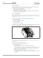
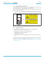
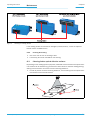
Maintenance Chapter 8 Operating Instructions CLV63x Bar Code Scanner 8.2.1 Cleaning the reading window Damage to the reading window! Reduced reading capacity due to scratches or smears on the reading window! The reading window for versions CLV63x-xxx0 is made of glass. ¾ Do not use aggressive cleaning agents. ¾ Do not use cleaning agents which cause increased abrasion (e.g. powder). ¾ Avoid cleaning motions on the reading window which could cause scratches or abrasion. Damage to the reading window! Reduced reading capacity due to scratches or smears on the reading window! The reading window for versions CLV63x-xxx1 is made of plastic. Important ¾ Only clean the reading window with a damp cloth. ¾ Use mild cleansing agents without powder. Do not use strong cleansing agents such as acetone. ¾ Avoid cleaning motions on the reading window which could cause scratches or abrasion. Electrostatic charges cause dust particles to stick to the reading window. This effect can be combated by using anti-static SICK synthetic cleaner (no. 5600006) in combination with a SICK lens cloth (no. 4003353). Cleaning the reading window: 72 ¾ Switch off the device while you are cleaning it (see Laser protection). ¾ Use a clean, soft brush to free the (glass) reading window from dust. ¾ If necessary, additionally clean the (glass) reading window with a clean, damp, lint-free cloth and a mild, anti-static window cleaning fluid. ¾ Only clean the (plastic) reading window with a clean, damp, lint-free cloth and a mild, anti-static window cleaning fluid. © SICK AG · Division Auto Ident · Germany · All rights reserved 8011970/S345/2008-04-16 Operating Instructions Maintenance Chapter 8 CLV63x Bar Code Scanner Fig. 8-1: Cleaning the reading window If the reading window is scratched or damaged (cracked, broken), it must be replaced. Please contact the SICK Service. 8.2.2 Cleaning the housing ¾ Use a soft cloth to free the housing of dust. ¾ If necessary, also clean the LEDs on the housing. 8.3 Cleaning further optical effective surfaces Depending on the reading system equipment, additional external sensors with optical effective surfaces can be installed (e.g. photoelectric reflex switch for external reading pulsing). Soiling of these sensors can cause incorrect switching behaviour. ¾ In order to prevent incorrect switching behaviour, remove soiling from the optical effective surfaces of the external sensors. Fig. 8-2: 8011970/S345/2008-04-16 Cleaning of the external optical sensors (reading pulse generator) © SICK AG · Division Auto Ident · Germany · All rights reserved 73 Maintenance Chapter 8 Operating Instructions CLV63x Bar Code Scanner 8.4 Checking the incremental encoder If an optional incremental encoder is used, the position of the friction wheel at the drive system should be checked at regular intervals. ¾ Ensure that the incremental encoder has direct and fixed contact with the drive system and that the friction wheel rotates without slipping. 8.5 Replacing a bar code scanner Incorrect or damaged bar code scanners have to be removed and replaced with either new or repaired bar code scanners. Important Repairs to the bar code scanner should only be carried out by qualified and authorised SICK AG service staff. 8.5.1 Removing the bar code scanner 1. Switch the power supply to the bar code scanner off. 2. Disconnect all the connection cables on the bar code scanner. 3. Remove the bar code scanner from the holder. Mark the bar code scanner's situation and alignment on the holder or environment. 4. If available, remove the Micro SD memory card (optional) with the stored parameter set from the faulty bar code scanner (see chapter 4.7.4 Parameter set on the Micro SD memory card (optional), page 37). To do this, carefully open the black rubber cover and slightly press on the memory card in order to unlock it. 5. Insert the memory card accordingly into the empty space of the new, turned-off bar code scanner the right way round (contacts to the back and top) until it is locked. 6. Close the rubber cover. 8.5.2 Replacing the bar code scanner 1. Align and install the new or repaired bar code scanner (see chapter 5 Installation, page 39). Observe any marks made previously on the holder or the environment (chapter 8.5.1 Removing the bar code scanner, page 74). 2. Reconnect connection cables to the bar code scanner (see chapter 6 Electrical installation, page 49). 3. Switch the power supply to the bar code scanner back on. The bar code scanner starts with the default setting. 4. If, as an option, a Micro SD memory card has been inserted into the bar code scanner or a parameter memory module CMC600 into connection module CDB620/CDM420, the new bar code scanner will automatically load the stored parameter set from the memory card or CMC600 into its permanent memory. If both a memory card and a CMC600 are available, the bar code scanner will load the parameter set from the CMC600. - or Without Micro SD memory card /parameter memory module CMC600: Connect to the bar code scanner via the SOPAS-ET configuration software, transfer the configuration stored on the PC via download to the bar code scanner and permanently store the configuration there. 74 © SICK AG · Division Auto Ident · Germany · All rights reserved 8011970/S345/2008-04-16 Operating Instructions Troubleshooting Chapter 9 CLV63x Bar Code Scanner 9 Troubleshooting This chapter describes how errors at the bar code scanner can be recognised and eliminated. 9.1 Overview of errors and malfunctions which could occur 9.1.1 Installation error • The bar code scanner has been unsuitably aligned to objects with bar codes (e.g. visual glare) • Reading pulse sensor has been incorrectly positioned (e.g. internal reading gate opens too late or shuts too early) • Incremental encoder (optional) positioned incorrectly 9.1.2 • Electrical installation error Interfaces of the bar code scanner wired incorrectly 9.1.3 Configuration error • Functions have not been adjusted to the local conditions, e.g. parameters for the data interface set incorrectly • Device-related limits have not been considered, e.g. reading distance, aperture angle • Selected trigger source for reading pulse incorrect 9.1.4 Malfunctions during operation • Start/Stop operation: External reading pulse is missing, more than one object is in the reading area • Device error (hardware/software) 9.2 Detailed malfunction analysis 9.2.1 LEDs on the bar code scanner The following statuses can, among other things, be read from the LEDs on the bar code scanner's housing (see chapter 4.7.2 LEDs on the bar code scanner's housing, page 34): • Reading reliability (Bar graph, diagnostic mode) • Ready • Status of the reading result (Result) • Data trafic on the Host-, Aux- and CAN-interface The LEDs can display possible malfunctions or errors. Please refer to the system information for further details. 8011970/S345/2008-04-16 © SICK AG · Division Auto Ident · Germany · All rights reserved 75 Troubleshooting Chapter 9 Operating Instructions CLV63x Bar Code Scanner 9.2.2 System information The bar code scanner displays errors in various ways. The error output is hierarchised and always allows a detailed analysis: • Communication errors can occur while transferring telegrams to the bar code scanner. In this case, the bar code scanner returns an error code. • Error codes are written into a status protocol for errors which occur during a reading (chapter 9.3 Status protocol, page 76). 9.3 Important Status protocol The status protocol remains even after switching the bar code scanner off and on again. The bar code scanner differentiates between four error types: • Information • Warning • Error • Fatal error The bar code scanner only saves the last five entries for each of the error types. 9.3.1 Displaying the status protocol using the SOPAS-ET configuration software In order to display the status protocol, the SOPAS-ET configuration software has to be online and connected to the bar code scanner. 1. Connect the SOPAS-ET configuration software with the device. 2. Open the project tree CLV63X, SERVICE, SYSTEMSTATUS, register tab SYSTEMINFORMATION. 9.4 SICK Support If an error cannot be eliminated, it is possible that the bar code scanner is defective. The bar code scanner cannot be repaired by the user, meaning that it is not possible to re-establish functions after a failure. However, the bar code scanner can be rapidly replaced by the user. See chapter 8.5 Replacing a bar code scanner, page 74. ¾ If an error occurs which cannot be eliminated, please contact SICK Service: • International: Competent SICK branch office or SICK subsidiary – Telephone numbers and e-mail addresses on the reverse side of these operating instructions – For the postal address please visit www.sick.com ¾ Important 76 Only return devices after consultation with the SICK Service. Repairs to the bar code scanner should only be performed by qualified and authorised SICK AG service staff. © SICK AG · Division Auto Ident · Germany · All rights reserved 8011970/S345/2008-04-16 Operating Instructions Technical data Chapter 10 CLV63x Bar Code Scanner 10 Technical data 10.1 Datenblatt Barcodescanner CLV63x (Linien-/ Rasterscanner) Type CLV63x Bar Code Scanner Focus Fixed focus Reading window Line / Raster scanner: With front/side reading window (with angle attachment: light entrance/exit under 105°) Laser diode (wavelength) Red light (λ = 655 nm) MTTR of the laser diode 20,000 h Device laser class Class 2 in accordance with IEC 60825-1 and EN 60825-1, see warning sign on device for date of publication Useable aperture angle max. 50° (front reading window and side reading window) Scan/decoder frequency 400 ... 1,200 Hz Resolution 0,15 ... 1.0 mm (5.9 ... 39.5 mil) (type-dependent) Raster height 15 mm (0.6 in) (8 lines) with 200 mm (7.9 in) reading distance (front reading window) Bar code print contrast (PCS) ≥ 60 % Ambient light compatibility 2,000 lx (on bar code) Number of bar codes per scan 1 ... 20 standard decoder; 1 ... 6 SMART decoder Number of bar codes per reading 1 ... 50 bar codes (auto-discriminating) gate1) Bar code types Code 39, Code 128, Code 93, Codabar, EAN, EAN 128, UPC, 2/5 Interleaved, Pharmacode Bar code lengths Max. 50 characters (max. 5,000 characters across all bar codes per reading gate, 500 characters with multiplexer function (CAN)) Print ratio 2:1 ... 3:1 Number of multireads 1 ... 99 Memory card for parameters (cloning) Micro SD card (flash card) 512 MB, optional Optical indicators 6 LEDs: Ready, Result, Laser, Data, CAN, LNK TX and bargraph display Acoustic display Beeper, can be switched off, with function for result status display Control elements 2 buttons (selecting and starting/stopping functions) Reading pulsing Pulse sources for start: Switching inputs "Sensor 1"2) and/or "Sensor 2"; command; Automatic Cycle; CAN Pulse sources for stop: Reading pulse source, "Sensor 1", "Sensor 2", command, timer, good read, condition "Host" data interface Serial: RS-232 or RS-422/485; Ethernet (port 2112), adjustable data format (serial) and data output format Data transfer rate 2,4 ... 115.2 kbd Protocols SICK standard (SOPAS-Cola-A) Physical configurations Stand-alone "Aux" data interface Serial: RS-232 (57.6 kbd; 8 data bits, no parity, 1 stop bit); Ethernet (port 2111); fixed data output format "Ethernet" data interface Only for Ethernet version: 10/100 MBit/s, TCP/IP, half/full duplex "CAN" data interface 20 kBit/s ... 1 MBit/s, SICK CAN-SENSOR network (Master, Slave, Multiplexer) Digital switching inputs Standard version: 2 ("Sensor 1", "Sensor 2"), 2 additional inputs via CMC600 in CDB620 Ethernet version: 1 ("Sensor 1"), 2 additional inputs via CMC600 in CDB620, optodecoupled, Vin = max. 32 V, reverse polarity protected, can be wired with PNP output, configurable debouncing 0 ...10.000 ms 8011970/S345/2008-04-16 © SICK AG · Division Auto Ident · Germany · All rights reserved 77 Technical data Chapter 10 Operating Instructions CLV63x Bar Code Scanner Type CLV63x Bar Code Scanner Digital switching outputs Standard version: 2 ("Result 1", "Result 2"), 2 additional outputs via CMC600 in CDB620 Ethernet version: no output, 2 outputs via CMC600 in CDB620 PNP, Iout = max. 100 mA, short circuit-proof, configurable impulse duration (static, 10 ... 1.000 ms) Electrical connection Standard version: Cable (0.9 m (3 ft)) with 15-pole D-Sub-HD plug Ethernet version: Revolving connector unit with two M12 circular connectors (12-pole plug, 4-pole socket) Operating voltage 18 ... 30 V DC in accordance with IEC 364-4-41 (SELV respectively PELV acc. to IEC 60364-4-41 (2005)) Current consumption Line / Raster scanner: typically 5 W with DC 24 V ± 10% Housing Die-cast aluminium Reading window material Glass or plastic, see type plate CLV63x-xxxy (y = 0: glass, y = 1: plastic) Electrical safety according to EN 60950-1 (2006-04) Safety class III, according to EN 61140 (2002-03) Enclosure rating IP 65, according to EN 60529 (1991-10); A1 (2002-02) EMC test Emission: according to EN 61000-6-3 (2001-10); immunity: according to EN 61000-6-2 (2005-08) Vibration-/ shock-test according to EN 60068-2-6 (1995) / according to EN 60068-2-27 (1993) Weight Standard version: 320 g with connection cable (front reading window), 340 g (side reading window) Ethernet version: 250 g without connection cables (front reading window), 270 g (side reading window) Ambient operating temperature/ 0 ... +40 °C/–20 ... +70 °C storage temperature Max. rel. humidity 90%, no condensation Housing colour SICK Blue (light blue according to RAL 5012) 1) Reading gate: code evaluation time window created internally by the reading pulse 2) Ethernet version: only switching input "Sensor 1" Tab. 10-1: 78 Technical specifications for the CLV63x Bar Code Scanner (line/raster scanner) © SICK AG · Division Auto Ident · Germany · All rights reserved 8011970/S345/2008-04-16 Operating Instructions Technical data Chapter 10 CLV63x Bar Code Scanner 10.2 Data sheet for the CLV63x Bar Code Scanner (line scanner with oscillating mirror) The technical specifications correspond to those of the CLV63x Bar Code Scanner (line/raster scanner), except for the following variations: Type CLV63x Bar Code Scanner Reading window side reading window, light exit under 105° (default setting) Useable aperture angle max. 50° Oscillating mirror functions Uncontrolled operation: • Fixed (position can be adjusted) or • Continuous, free oscillation Controlled operation (start/stop condition can be adjusted): • Triggered oscillation (start position and number of oscillations can be adjusted) • One-shot: One-time oscillation in forward and return motion (start position can be adjusted) In every oscillation mode, the amplitude can be adjusted separately for each of the two deflection directions. The deflection speed ratio of one deflection direction to the other can be adjusted within the selected periodic time for a complete oscillation sequence. Oscillation frequency / Periodic time 0.5 ... 6.25 Hz / 2,000 ... 160 ms Max. angle of deflection (amplitude) +20° ... –20° Current consumption Typically 6 W with DC 24 V ±10 % Weight Standard version: 420 g Ethernet version: 350 g Tab. 10-2: Technical specifications for the CLV63x Bar Code Scanner (line scanner with oscillating mirror) 8011970/S345/2008-04-16 © SICK AG · Division Auto Ident · Germany · All rights reserved 79 Chapter 10 Technical data Operating Instructions CLV63x Bar Code Scanner 10.3 Test code Code 39/ITF Print ratio 2:1 Print contrast > 90 % Tilt ±10° Ambient light < 2 000 lx Good read rate > 75 % Tab. 10-3: 10.3.1 Fig. 10-1: 80 Specification diagrams Reading conditions for all specification diagrams Reading ranges of the CLV630 Bar Code Scanner (Long-range) CLV630: Reading ranges of the line scanner/raster scanner with front reading window © SICK AG · Division Auto Ident · Germany · All rights reserved 8011970/S345/2008-04-16 Operating Instructions Technical data Chapter 10 CLV63x Bar Code Scanner Fig. 10-2: CLV630: Reading ranges of the line scanner/raster scanner with side reading window Fig. 10-3: CLV630: Reading ranges of the line scanner with oscillating mirror (side reading window) 8011970/S345/2008-04-16 © SICK AG · Division Auto Ident · Germany · All rights reserved 81 Technical data Chapter 10 Operating Instructions CLV63x Bar Code Scanner Fig. 10-4: CLV630: Set of characteristic curves for scan frequency, depending on the reading distance and resolution (line scanner/ raster scanner with front reading window) Important With the CLV630 Line Scanner/Raster Scanner with side reading window, the reading distance values in the above diagram have an offset of 16 mm towards the reading window for all scan frequencies. With the line scanner with oscillating mirror, the values have an offset of 19 mm towards the reading window. 82 © SICK AG · Division Auto Ident · Germany · All rights reserved 8011970/S345/2008-04-16 Operating Instructions Technical data Chapter 10 CLV63x Bar Code Scanner 10.3.2 Reading ranges of the CLV631 Bar Code Scanner (Mid-range) Fig. 10-5: CLV631: Reading ranges of the line scanner/raster scanner with front reading window Fig. 10-6: CLV631: Reading ranges of the line scanner/raster scanner with side reading window 8011970/S345/2008-04-16 © SICK AG · Division Auto Ident · Germany · All rights reserved 83 Technical data Chapter 10 Operating Instructions CLV63x Bar Code Scanner Fig. 10-7: CLV631: Reading ranges of the line scanner with oscillating mirror (side reading window) Fig. 10-8: CLV631: Set of characteristic curves for scan frequency, depending on the reading distance and resolution (line scanner/ raster scanner with front reading window) Important With the CLV631 Line Scanner/Raster Scanner with side reading window, the reading distance values in the above diagram have an offset of 16 mm towards the reading window for all scan frequencies. With the line scanner with oscillating mirror, the values have an offset of 19 mm towards the reading window. 84 © SICK AG · Division Auto Ident · Germany · All rights reserved 8011970/S345/2008-04-16 Operating Instructions Technical data Chapter 10 CLV63x Bar Code Scanner 10.3.3 Fig. 10-9: Reading ranges of the CLV632 Bar Code Scanner (Short-range) CLV632: Reading ranges of the line scanner/raster scanner with front reading window 8011970/S345/2008-04-16 © SICK AG · Division Auto Ident · Germany · All rights reserved 85 Chapter 10 Technical data Operating Instructions CLV63x Bar Code Scanner Fig. 10-10: CLV632: Reading ranges of the line scanner/raster scanner with side reading window 86 © SICK AG · Division Auto Ident · Germany · All rights reserved 8011970/S345/2008-04-16 Operating Instructions Technical data Chapter 10 CLV63x Bar Code Scanner Fig. 10-11: CLV632: Reading ranges of the line scanner with oscillating mirror (side reading window) Fig. 10-12: CLV632: Set of characteristic curves for scan frequency, depending on the reading distance and resolution (line scanner/ raster scanner with front reading window) Important With the CLV632 Line Scanner/Raster Scanner with side reading window, the reading distance values in the above diagram have an offset of 16 mm towards the reading window for all scan frequencies. With the line scanner with oscillating mirror, the values have an offset of 19 mm towards the reading window. 8011970/S345/2008-04-16 © SICK AG · Division Auto Ident · Germany · All rights reserved 87 Chapter 10 Technical data Operating Instructions CLV63x Bar Code Scanner 10.3.4 Deflection range of line scanner with oscillating mirror Fig. 10-13: CLV630-6000/CLV630-6120: Deflection range as a function of the reading distance, deflection angle and resolution Fig. 10-14: CLV631-6000/CLV631-6120: Deflection range as a function of the reading distance, deflection angle and resolution 88 © SICK AG · Division Auto Ident · Germany · All rights reserved 8011970/S345/2008-04-16 Operating Instructions Technical data Chapter 10 CLV63x Bar Code Scanner Fig. 10-15: CLV632-6000/CLV632-6120: Deflection range as a function of the reading distance, deflection angle and resolution 8011970/S345/2008-04-16 © SICK AG · Division Auto Ident · Germany · All rights reserved 89 Chapter 10 Technical data Operating Instructions CLV63x Bar Code Scanner 10.4 CLV63x Bar Code Scanner dimensional drawings 10.4.1 CLV63x-0000 and CLV63x-1000 Bar Code Scanner dimensional drawing Fig. 10-16: Standard version: Dimensions of the bar code scanner with front reading window (CLV63x-0000 and CLV63x-1000) 90 © SICK AG · Division Auto Ident · Germany · All rights reserved 8011970/S345/2008-04-16 Operating Instructions Technical data Chapter 10 CLV63x Bar Code Scanner 10.4.2 CLV63x-2000 and CLV63x-3000 Bar Code Scanner dimensional drawing Fig. 10-17: Standard version: Dimensions of the bar code scanner with side reading window (CLV63x-2000 and CLV63x-3000) 8011970/S345/2008-04-16 © SICK AG · Division Auto Ident · Germany · All rights reserved 91 Chapter 10 Technical data Operating Instructions CLV63x Bar Code Scanner 10.4.3 CLV63x-6000 Bar Code Scanner dimensional drawing Fig. 10-18: Standard version: Dimensions of the bar code scanner with oscilliating mirror (CLV63x-6000) 92 © SICK AG · Division Auto Ident · Germany · All rights reserved 8011970/S345/2008-04-16 Operating Instructions Technical data Chapter 10 CLV63x Bar Code Scanner 10.4.4 CLV63x-0120 and CLV63x-1120 Bar Code Scanner dimensional drawing Fig. 10-19: Ethernet version: Dimensions of the bar code scanner with front reading window (CLV63x-0120 and CLV63x-1120) 8011970/S345/2008-04-16 © SICK AG · Division Auto Ident · Germany · All rights reserved 93 Chapter 10 Technical data Operating Instructions CLV63x Bar Code Scanner 10.4.5 CLV63x-2120 and CLV63x-3120 Bar Code Scanner dimensional drawing Fig. 10-20: Ethernet version: Dimensions of the bar code scanner with side reading window (CLV63x-2120 and CLV63x-3120) 94 © SICK AG · Division Auto Ident · Germany · All rights reserved 8011970/S345/2008-04-16 Operating Instructions Technical data Chapter 10 CLV63x Bar Code Scanner 10.4.6 CLV63x-6120 Bar Code Scanner dimensional drawing Fig. 10-21: Ethernet version: Dimensions of the bar code scanner with oscilliating mirror (CLV63x-6120) 8011970/S345/2008-04-16 © SICK AG · Division Auto Ident · Germany · All rights reserved 95 Chapter 10 Technical data Operating Instructions CLV63x Bar Code Scanner 96 © SICK AG · Division Auto Ident · Germany · All rights reserved 8011970/S345/2008-04-16 Operating Instructions Appendix Chapter 11 CLV63x Bar Code Scanner 11 Appendix 11.1 Appendix overview The appendix contains the following additional information: • Configuring the bar code scanner System with command strings • Help table for calculating the code length of a bar code • Ordering information • Supplementary documentation (overview) • Glossary • Copy of EC Declaration of Conformity • Code samples of bar codes 11.2 Configuring the bar code scanner with command strings As an alternative to the SOPAS-ET configuration software, the bar code scanner can also be configured and operated with command strings via all the data interfaces. The command strings can be displayed separately via the SOPAS-ET configuration software. Important Both the command strings and the SOPAS-ET configuration software are based on command language which directly accesses the command interpreter of the bar code scanner. This command language must be used with care as the bar code scanner executes sent commands immediately. Parameter values altered via commands are at first only active in the current parameter set in the working memory (RAM) of the bar code scanner. To save in the permanent memory, the altered parameter set must be copied into the PROM using a special command, this ensures that the alterations are not lost when the power supply is switched off. Command strings for triggering the reading pulse: • START: <STX>sMN mTCgateon<ETX> • STOP: <STX>sMN mTCgateoff<ETX> If the commands are entered via the terminal emulator in the SOPAS-ET configuration software, the two control characters <STX> and <ETX> are omitted. Connection to the bar code scanner when using the terminal emulator and Ethernet: 1. Select TOOLS/TERMINAL in the SOPAS-ET configuration software menu to call up the terminal emulator and in the terminal emulator, select CONNECTION/CONNECT to call up the connection assistant. 2. Select option USER DEFINED CONNECTION in the connection assistant and confirm by pressing NEXT. 3. Select option TCP/IP and confirm by pressing NEXT. 4. Select option SHOW ONLY COLA TELEGRAMS. 5. Enter the bar code scanner's IP address in the relevant field and confirm by pressing NEXT. 6. In the ADDRESSING MODE selection list, select BY NAME and confirm the settings by pressing CONNECT. The connection with the bar code scanner is established. The command strings can be transferred. 8011970/S345/2008-04-16 © SICK AG · Division Auto Ident · Germany · All rights reserved 97 Appendix Chapter 11 Operating Instructions CLV63x Bar Code Scanner 11.3 Calculating the code length of a bar code The code length of a bar code corresponds to the number of characters used in the print image, including the check digit (if available). To scan (decode) a code, the code length must be input using the SOPAS-ET configuration software. Depending on the bar code type, the code length can be calculated by counting the bars and spaces according to the relevant formula in the following table. 1. Determine the bar code type and count the bars or wide elements (bars and spaces), incl. start and stop characters according to the information in the following table. 2. Calculate the bar code length according to the relevant formula. 3. Enter the results via the SOPAS-ET configuration software, as shown in column 4 of the table. Bar code type Count Code 39 Number of bars Number – 10 ICode = ————————— 5 Calculated code length 2/5 Interleaved Number of wide elements (bars and spaces) Number – 1 ICode = ————————— 2 Calculated code length EAN n/a UPC n/a Calculating the bar code length1)2) Input the SOPAS-ET configuration software 13 characters (normal version) Activate 13-digit 8 characters (short version) Activate 8-digit 12 characters (UPC A, normal version) Activate version A 6 characters (UPC E, short version) Activate version E Codabar Number of bars Number – 8 ICode = ————————— 4 Calculated code length Code 128 (character set A) Number of bars Number – 10 ICode = ————————— 3 Calculated code length EAN 128 Number of bars Number – 10 ICode = ————————— 3 Calculated code length Pharmacode Number of bars Number Number = code length 1) Check digit optional for code 39, 2/5 Interleaved, Codabar. Check digit is always integrated into the bar code print for EAN, UPC, code 128, code 93, EAN 128 according to the specification (automatically eliminated when the bar code scanner reading results are generated) 2) Apart from a few exceptions, every printed character represents an ASCII character which has to be decoded. Extended for code 39. The number of characters in the bar code scanner's data string may be greater than the number of characters in the print image for code 93, code 128 and EAN 128, since they are made up of several character sets. Tab. 11-1: 98 Help table for calculating the code length of a bar code © SICK AG · Division Auto Ident · Germany · All rights reserved 8011970/S345/2008-04-16 Operating Instructions Appendix Chapter 11 CLV63x Bar Code Scanner 11.4 Ordering information for bar code scanner and accessories 11.4.1 Ordering information for CLV63x Bar Code Scanner Order no. Type Scanning method Reading window Connection (design) CLV630: Long-range reading range 1040706 CLV630-0000 Line scanner On front Cable with connector 1041969 CLV630-0120 Line scanner On front Connector unit on device 1041970 CLV630-1000 Raster scanner On front Cable with connector 1041971 CLV630-1120 Raster scanner On front Connector unit on device 1041972 CLV630-2000 Line scanner On side Cable with connector 1041973 CLV630-2120 Line scanner On side Connector unit on device 1041974 CLV630-3000 Raster scanner On side Cable with connector 1041975 CLV630-3120 Raster scanner On side Connector unit on device 1041976 CLV630-6000 Line scanner with On side oscillating mirror Cable with connector 1041977 CLV630-6120 Line scanner with On side oscillating mirror Connector unit on device CLV631: Mid-range reading range 1041978 CLV631-0000 Line scanner On front Cable with connector 1041979 CLV631-0120 Line scanner On front Connector unit on device 1041980 CLV631-1000 Raster scanner On front Cable with connector 1041981 CLV631-1120 Raster scanner On front Connector unit on device 1041982 CLV631-2000 Line scanner On side Cable with connector 1041983 CLV631-2120 Line scanner On side Connector unit on device 1041984 CLV631-3000 Raster scanner On side Cable with connector 1041985 CLV631-3120 Raster scanner On side Connector unit on device 1041986 CLV631-6000 Line scanner with On side oscillating mirror Cable with connector 1041987 CLV631-6120 Line scanner with On side oscillating mirror Connector unit on device CLV622: Short-range reading range 1041988 CLV632-0000 Line scanner On front Cable with connector 1041989 CLV632-0120 Line scanner On front Connector unit on device 1041990 CLV632-1000 Raster scanner On front Cable with connector 1041991 CLV632-1120 Raster scanner On front Connector unit on device 1041992 CLV632-2000 Line scanner On side Cable with connector 1041993 CLV632-2120 Line scanner On side Connector unit on device 1041994 CLV632-3000 Raster scanner On side Cable with connector 1041995 CLV632-3120 Raster scanner On side Connector unit on device 1041996 CLV632-6000 Line scanner with On side oscillating mirror Cable with connector 1041997 CLV632-6120 Line scanner with On side oscillating mirror Connector unit on device Tab. 11-2: 8011970/S345/2008-04-16 Variants of the CLV63x Bar Code Scanner © SICK AG · Division Auto Ident · Germany · All rights reserved 99 Appendix Chapter 11 Operating Instructions CLV63x Bar Code Scanner 11.4.2 Accessories: Mounting devices Order no. Description 2020410 Fixing bracket incl. installation material. For dimensional drawing, see chapter 11.5.1 Dimensional drawing fixing bracket no. 2020410, page 106 2025526 Quick release clamp incl. installation material. For dimensional drawing, see chapter 11.5.2 Dimensional drawing of quick release clamp no. 2025526, page 107 2042800 Fixing Bracket incl. installation material. For dimensional drawing, see chapter 11.5.3 Dimensional drawing fixing bracket no. 2042800, page 108 2042801 Round rod holders for round rods and tubes with an outer diameter of 12...20 mm (0.47 ... 0.8 in), incl. installation material. For dimensional drawing, see chapter 11.5.4 Dimensional drawing of round rod holder no. 2042801, page 109 Tab. 11-3: 100 Fig. In stock accessories: Installation accessories © SICK AG · Division Auto Ident · Germany · All rights reserved 8011970/S345/2008-04-16 Operating Instructions Appendix Chapter 11 CLV63x Bar Code Scanner 11.4.3 Accessories: Connection modules Order no. Type Description 1042256 CDB620-001 Connection module for a CLV63x, with: • 1 x 15-pole D-Sub-HD device socket • 4 x cable connections M16 (clamping range Ø 4.5 ...10 mm (0.18 ... 0.39 in)) • Terminal strips (signal distribution unit) for wiring the data and function interfaces (digital switching inputs and outputs) • 1 x internal 9-pole D-Sub "Aux" plug • 9 x LED (status indicators) • Operating voltage 10...30 V DC • Polycarbonate housing, enclosure rating IP 651) • Operating temperature -352) ...+40 °C (-312) ... +104 °F) • Dimensions 124.2 mm x 113.1 mm x 53.9 mm (7.56 in x 6.54 in x2.74 in) • Weight approx. 260 g (9.17oz) 1042257 CDB620-101 As CDB620-001, but with: • 2 x cable connections M16 (clamping range Ø 4.5 ...10 mm (0.18 ... 0.39 in)) • 2 x 5-pole M12 circular connector (1 x plug, 1 x socket) 1042258 CDB620-201 As CDB620-001, but with: • 4 x cable connections M16 (clamping range Ø 4.5 ...10 mm (0.18 ... 0.39 in)) • 1 x cable connection M12 (clamping range Ø 4.5...7mm (0.18...0.28in)) 1025362 CDM4200001 Connection module for a CLV63x, with: • 1 x 15-pole D-Sub-HD device socket • 6 x cable connections M16 (clamping range Ø 4.5...10mm (0.18...0.39in)) • Terminal strips (signal distribution unit) for wiring the data and function interfaces (digital switching inputs and outputs) • 1 x internal 9-pole D-Sub "Aux" plug • 5 x LED (status indicators) • Operating voltage 10...30 V DC, current consumption 0.5 W without CLV63x • Polycarbonate housing, enclosure rating IP 651) • Operating temperature -352) ...+40 °C (-312) ... +104 °F) • Dimensions 191.9 mm x 166.2 mm x 69.7 mm (7.56in x 6.54in x2.74in) • Weight approx. 800 g (9.17oz) Application of CLV63x in combination with the parameter memory module CMC600 available from week 7/2008. 1028487 CDM4200004 As CDM420-0001, but for max. two CLV63x with: • 2 x 15-pole D-Sub-HD device sockets • 2 x internal 9-pole D-Sub "Aux" plug • 2 x 5 LED (status indicators) Application of CLV63x in combination with the parameter memory module CMC600 available from week 7/2008. Display 1) When using a SICK scanner standard connection cable 2) Dormant (no installation or electrical installation), up to –20 °C (-4 °F) Tab. 11-4: In stock accessories: Connection modules 8011970/S345/2008-04-16 © SICK AG · Division Auto Ident · Germany · All rights reserved 101 Appendix Chapter 11 Operating Instructions CLV63x Bar Code Scanner 11.4.4 Accessories: Extensions for connection modules Order no. Type Description 1042259 CMC600101 Parameter memory module (connection module cloning) • Plug-in using connection module CDB620 or CDM420 • Storage of the parameter set of CLV63x (from firmware V 1.00) • Rotary switch for activating CLV63x network operation • Operating voltage 10 ... 30 V DC using CDB620 or CDM420 • Current consumption 0.5 W • Operating temperature 0 ... +40 °C 2029466 CDM4001) Display module (connection display module) • In the optional housing cover for connection module CDM420 • Display of reading results and reading diagnosis data of CLV63x (from firmware V 1.00) • LCC with 4 x 20 characters, keyboard with 5 keys • Connection via flat cable • Operating voltage 18 ... 30 VDC using CDM420, current consumption 1 W • Operating temperature 0 ... +40 °C Prerequisite: Parameter memory module CMC600-101 for addressing the display. 2029468 CMP400 Power supply module (connection module power) • Installed in connection module CDM420 • Power supply of CLV63x from the alternating current network • Input voltage 100 ... 250 VAC/50 ...60 Hz • Output voltage 24 V DC, max. 10.8 W (short-circuit proof) • Connection to CDM420 via flat cable • Operating temperature 0 ... +40 °C 2030091 CMP4902) Power supply module (connection module power) • In the optional housing cover for connection module CDM420 • Power supply of CLV63x from the alternating current network • Input voltage 100 ... 250 V AC/50 ...60 Hz • Output voltage 24 V DC, max. 25 W (short-circuit proof) • Connection to CDM420 via flat cable • Operating temperature 0 ... +40 °C 1026241 CMF4001001 Field bus gateway (connection module field bus) • Installed in connection module CDM420 • Connection of a CLV63x (from firmware V 1.00) via RS-232 data interface to Profibus DP (slave) • Changeable front panel: 9-pole D-Sub socket (bus), enclosure rating IP 20 • On the gateway in the device, 5-pole terminal strip for connecting two digital inputs and outputs each • Connection to CDM420 via connector • Operating voltage 18 ... 30 VDC using CDM420, current consumption 2 W • Operating temperature 0 ... +40 °C • Configuration with PC software "ComPro" (included in delivery) • Configuration with SOPAS-ET from Q4/2007 102 © SICK AG · Division Auto Ident · Germany · All rights reserved Display 8011970/S345/2008-04-16 Operating Instructions Appendix Chapter 11 CLV63x Bar Code Scanner Order no. Type Description 1026643 CMF4001101 As CMF400-1001, but with: • Changeable front panel: 9-pole D-Sub socket (bus), enclosure rating IP65 Display 1028663 CMF4001201 As CMF400-1001, but with: • Changeable front panel: 2 x 5-pole M12 circular connector (1 x plug, 1 x socket) for bus, enclosure rating IP65 1026242 CMF4002101 Field bus gateway (connection module field bus) • Installed in connection module CDM420 • For connecting a CLV63x (from firmware V 1.00) via RS-232 data interface to DeviceNet (slave) • Changeable front panel: 5-pole M12-plug (bus), enclosure rating max. IP 65 • On the gateway in the device, 5-pole terminal strip for connecting two digital inputs and outputs each • Connection to CDM420 via connector • Operating voltage 18 ... 30 V DC using CDM490, current consumption 2 W • Operating temperature 0 ... +40 °C • Configuration with PC software "ComPro" (included in delivery) • Configuration with SOPAS-ET from Q4/2007 6029030 - Profibus connector, IP 65, for CMF400-1101 - 1) Simultaneous operation together with power supply module CMP490 not possible 2) Simultaneous operation together with display supply module CMD400 not possible Tab. 11-5: In stock accessories: Extensions for connection modules 11.4.5 Accessories: Separate field bus modules Order no. Type Description 1041251 CDF6000100 PROFIBUS DP Proxi • Connection of a CLV63x (from firmware V2.50) via RS-232 data interface to PROFIBUS DP • 1 x 15-pole D-Sub-HD socket for CLV63x • 1 x 5-pole M12 plug/socket for bus connection • 1 x 5-pole M12 plug for operating voltage • 1 x 4-pole M8 socket for configuration (Aux, RS-232) • 6 x LED (status indicators) • Operating voltage 24 V DC ± 20 %, current consumption type 5 W • Aluminium die casting housing, enclosure rating IP 65 • Operating temperature 0 ... + 40 °C (32 ... 104 °F) • Dimensions 225 mm (8.6 in) x 76,5 mm (3.03 in) x 47 mm (1.9 in) (without direct connections) • Weight approx. 590 g (9.17oz) • Configuration: via 3 x rotary switches and SOPAS-ET Tab. 11-6: Display In stock accessories: Separate field bus modules 8011970/S345/2008-04-16 © SICK AG · Division Auto Ident · Germany · All rights reserved 103 Appendix Chapter 11 Operating Instructions CLV63x Bar Code Scanner 11.4.6 Accessories: Cables for standard version Order no. Description 6034417 Extension cable for data and function interfaces, 15 shielded, with 15-pole D-Sub-HD socket and 15-pole, DSub-HD plug 2 m (6.56 ft) CLV63x to CDB620, CDM420 6034418 Extension cable for data and function interfaces, Ø 7 mm (0.28 in), shielded, with 15-pole D-Sub-HD socket and open end 2 m (6.56 ft) CLV63x for free wiring 6034419 Extension cable for data and function interfaces, Ø 6.8 16 x mm (0.27 in), shielded, for lengths up to 3 m (9.84 ft) 0.14 mm² (26 AWG) 2043413 Tab. 11-7: Wires 15 x 0.16 mm² (26 AWG) Description 6034414 Ethernet cable (patch), twisted pair, shielded, with 42x2 pole M12 round plug (D coded), IP 65 and 8-pole RJ45 plug Wires 6030928 6034420 6034421 2041834 2042914 Ethernet cable (patch), twisted pair, shielded, with 2 x 4-pole M12 round plug (D coded), IP 65 2x2 Tab. 11-8: CLV63x to CDB620, CDM420 Length Connection 2 m (6.56 ft) CLV63x to Ethernet 3 m (9.84 ft) 5 m (16.4 ft) 2 m (6.56 ft) CLV63x to Ethernet 3 m (9.84 ft) 5 m (16.4 ft) Connection cable for data and function interfaces, shielded, with 12-pole M12 round socket and 15-pole, D-Sub-HD plug, IP 67 12 0.9 m (3 ft) CLV63x to CDB620, CDM420 2 m (6.56 ft) 3 m (9.84 ft) 2042915 6034605 Sold by the metre 10 m (32.8 ft) 6034422 2042916 3 m (9.84 ft) Accessories: Cables for Ethernet version Order no. 6034415 Connection In stock accessories: Cables and connectors for the standard version of the bar code scanner 11.4.7 6029630 Length 5 m (16.4 ft) Connection cable for data and function interfaces, Ø 6.2 mm (0.24 in), shielded, with 12-pole M12 round socket and open end. 12 x 0.14 mm² (26 AWG) 5 m (16.4 ft) CLV63x for free wiring In stock accessories: Cables and connectors for the Ethernet version of the bar code scanner 11.4.8 Accessories: General cables and connectors Order no. Description Wires Length Connection/view 6021164 CAN data cable, shielded, twisted pair, with 5-pole M12 socket and 5-pole M12 plug, IP 65, PVC-free 2 x 0.32 mm² (28 AWG) 2 x 0.25 mm² (28 AWG) 1 m (39.37 in) CLV63x via CDB620 to CAN bus 6021165 6021168 5 m (196.85 in) 6021166 CAN data cable, Ø 6.8 mm (0.27in), shielded, twisted pair, with 5-pole M12 socket and open end (wire end ferrules), IP65, PVC-free 6021167 CAN terminal resistance, shielded, with 5-pole M12 plug, IP 65 104 3 m (118.11 in) 2 x 0.32 mm² (28 AWG) 2 x 0.25 mm² (28 AWG) 5 m (196.85 CLV63x via CDB620 to CAN in) bus - © SICK AG · Division Auto Ident · Germany · All rights reserved CAN bus connection 8011970/S345/2008-04-16 Operating Instructions Appendix Chapter 11 CLV63x Bar Code Scanner Order no. Description Wires Length Connection/view 6027048 Unitronic CAN data cable, Ø 9.7 mm (0.38 in), twisted pair 2 x 2 x 0.5 mm² (21 AWG) Sold by the metre CAN-Bus 2014054 RS-232 data cable, shielded, with 2 x 9 -pole D-Sub 3 sockets. SICK null modem cable (pin 2 and pin 3 crossed) 3 m (118.11 CLV63x to PC in) 2030490 Data cable with 9-pole D-Sub plug and 3-pole molex 3 plug. For configuring the CMF400 with PC software "ComPro" Required in addition to the extension: Data cable no. 2014054 0.25 m (9.84 PC to CMF400 in) 6025906 Power supply line, with 5-pole M12 socket (direct), A coded and open end 5 x 0,34 mm² (28 AWG) 2 m (78.74 in) 6025908 As No. 6025906, but longer 5 x 0,34 mm² (28 AWG) 10 m (394 in) 6025909 Power supply line, with 5-pole M12 socket (90° off- 5 x 0.34 mm² set), A coded and open end (28 AWG) 2 m (78.74 in) 6025911 As No. 6025909, but longer 10 m (394 in) 6025931 Connection cable for switching input or output, with 5-pole M12 plug (direct), A coded and 5-pole M12 socket (direct), A coded 2 m (78.74 in) CDF600 at sensors and PLC 6021195 Data cable (RS-323), shielded, with 4-pole M8 plug and 9-pole socket. For CDF600 configuration with SOPAS-ET 2 m (78.74 in) CDF600 on PC 6021156 Terminating resistor for PROFIBUS, 5-pole M12 plug (direct), B coded - On PROFIBUS 6021353 5-pole M12 socket (direct), B coded, for PROFIBUS connection cable - - CDF600 on PORFIBUS (Bus IN) 6021354 5-pole M12 plug (direct), B coded, for PROFIBUS connection cable - 6021355 PROFIBUS connection, shielded 2 x 0,34 mm² (28 AWG) Sold by the metre 4038847 Sealing rubber IP 65 for extension cables with 15pole D-Sub connectors - - 6009438 D-Sub connector housing (metal) for 9-pole or 15pole HD inserts - - 6010019 D-Sub connector insert, 15-pole HD female multipoint connector (socket), hand soldering - - 6010020 D-Sub connector insert, 15-pole HD male multipoint connector (plug), hand soldering - Tab. 11-9: 5 x 0,34 mm² (28 AWG) CDF600 at power supply CDF600 on PORFIBUS (Bus OUT) PROFIBUS network In stock accessories: General cables and connectors for bar code scanner 8011970/S345/2008-04-16 © SICK AG · Division Auto Ident · Germany · All rights reserved 105 Chapter 11 Appendix Operating Instructions CLV63x Bar Code Scanner 11.4.9 Accessories: Reading pulse sensors Important The SICK catalog "SENSICK Sensoren for Automation" (order no. 8006530, English) contains a large selection of photoelectric reflex switches and photoelectric proximity switches as well as accessories (holders, connection cables). 11.4.10 Accessories: Memory Media Order no. Description 4051366 Micro SD memory card (Flash-Card), 512 MB Tab. 11-10: In stock accessories: Memory media for CLV63x Bar Code Scanner 11.5 Dimensional drawing accessories 11.5.1 Dimensional drawing fixing bracket no. 2020410 Included to fix the bar code scanner to the bracket: 2 x cylinder head screws M5 x 8 mm (0.32 in), with hexagon socket, self-locking Fig. 11-1: 106 Dimensions of the fixing bracket no. 2020410 © SICK AG · Division Auto Ident · Germany · All rights reserved 8011970/S345/2008-04-16 Operating Instructions Appendix Chapter 11 CLV63x Bar Code Scanner 11.5.2 Dimensional drawing of quick release clamp no. 2025526 Included to fix the bar code scanner to the clamp: 2 x cylinder head screws M5 x 8 mm (0.32 in), with hexagon socket, self-locking Fig. 11-2: 8011970/S345/2008-04-16 Dimensions of the quick release clamp no. 2025526 © SICK AG · Division Auto Ident · Germany · All rights reserved 107 Chapter 11 Appendix Operating Instructions CLV63x Bar Code Scanner 11.5.3 Dimensional drawing fixing bracket no. 2042800 Included to fix the bar code scanner to the bracket: • 3 x cylinder head screws M5 x 8 mm (0.32 in), with hexagon socket, self-locking • 3 x spring washer A5 Fig. 11-3: 108 Dimensions of the fixing bracket no. 2042800 © SICK AG · Division Auto Ident · Germany · All rights reserved 8011970/S345/2008-04-16 Operating Instructions Appendix Chapter 11 CLV63x Bar Code Scanner 11.5.4 Dimensional drawing of round rod holder no. 2042801 Included to fix the bar code scanner to the holder: • 3 x cylinder head screws M5 x 8 mm (0.32 in), with hexagon socket, self-locking • 3 x spring washer A5 Fig. 11-4: Dimensions of the round rod holder no. 2042801 8011970/S345/2008-04-16 © SICK AG · Division Auto Ident · Germany · All rights reserved 109 Appendix Chapter 11 Operating Instructions CLV63x Bar Code Scanner 11.6 Supplementary documentation Order no. Title Language Contents 8012119 Operating instructions "Connection module CDB620“ German/ English Description of the wiring for the bar code scanner with the host/PLC/sensor using connection module CDB620 8010004 Operating instructions "Connection module CDM4200001“ German/ English Description of the wiring for the bar code scanner with the host/PLC/sensor using connection module CDM420 8011155 Operating instructions "Connection module CDM4200004“ German/ English Description of the wiring for two bar code scanners with the host/PLC/sensor using connection module CDM420 8012120 Operating instructions "Parameter memory module CMC600“ German/ English Description of operating the module in connection module CDB620 or CDM420 8010372 Operating instructions "Display module CMD400“ German/ English Description of operating the module in connection module CDM420 8010365 Operating instructions "Power supply module CMP400“ German/ English Description of installing the module in connection module CDM420 8010601 Operating instructions "Power supply module CMP490“ German/ English Description of installing the module in connection module CDM420 8010461 Operating instructions "Field bus gateway CMF4001x01 for Profibus-DP“ German Description of installing and operating (configuring) the module in connection module CDM420 8010463 Operating instructions "Field bus gateway CMF4002101 for DeviceNet“ German Description of installing and operating (configuring) the module in connection module CDM420 8012213 Operating instruction "Field bus module CDF600-0100 for PROFIBUS-DP" German Description of installation, operation and configuration 8009179 Operating instructions "Use of the CAN interface" German Description of setting up a CAN scanner network (electrical connection, configuring the bar code scanner, functions) and integrating it in a CAN open network Tab. 11-11: Supplementary documentation 110 © SICK AG · Division Auto Ident · Germany · All rights reserved 8011970/S345/2008-04-16 Operating Instructions Appendix Chapter 11 CLV63x Bar Code Scanner 11.7 Glossary Also see the SOPAS-ET configuration software online help for further terms. Aperture angle α Aperture within the boundaries of which the bar code scanner is able to detect codes (through the lenses). A V-shaped area appears radially in front of the reading window, at right angles to the conveyor system (reading from above), in which the codes to be read must be positioned. Aspect ratio For bar codes with the code height (strip length) to code length (number of characters) ratio. Aux interface Logical auxiliary data interface of the bar code scanner with a fixed data output format, physically switched to RS-232 (Aux) and Ethernet (port 2111). With this data interface, access to the bar code scanner for the configuration is always possible with the PC and the SOPASET configuration software. The data interface is also used for diagnosis (output of reading diagnosis data or monitoring the data traffic on the Host interface). For the physical RS-232 interface, the following applies: fixed data format, data transfer rate 57.6 kbd. The data output to the PC via RS-232 can be switched off, existing Aux interface communication via the Ethernet interface (port 2111) remains active. Bar code Field of dark strips (bars) and light spaces (elements) arranged in parallel, which, by working to a certain rule (specification), can be represented on the medium (subsurface) by various print processes. A user-readable (alpha)numeric character is produced from each machinereadable, corresponding number and combination of strips and spaces. Since the entire coded information, framed by start and stop characters, is available as a whole in one dimension and is also usually analysed by line, bar codes are also referred to as linear codes. The various code types differ in their codeable character inventory, design (number of elements per character, number of characters, start/stop characters, check characters), their information density and in their print tolerances. The length of the code strips and spaces has no bearing on the information content. However, longer code strips and spaces can be more easily analysed by the reading device. CAN interface Physical data interface. Controls construction of a rapid SICK-specific CAN SENSOR network with various functions (e.g. multiplexer, master/slave). Access to the CLV63x Bar Code Scanner for configuration is possible via the CAN interface (network) using the SOPAS-ET configuration software in remote mode. Code geometry Code length and height dimensions. 8011970/S345/2008-04-16 © SICK AG · Division Auto Ident · Germany · All rights reserved 111 Chapter 11 Appendix Operating Instructions CLV63x Bar Code Scanner Command strings, commands User interface to the bar code scanner, as an alternative to the SOPAS-ET configuration software. The command string form a clearly structured command language for changing the parameter value sets in the bar code scanner online. Directly accesses the command interpreter of the bar code scanner. Use of the host requires a corresponding programming task. The SOPAS-ET configuration software is based on the command strings. Configuration file Project file for the SOPAS-ET configuration software in which either only one complete parameter value set for a device or, if several devices are grouped into one project, the complete parameter value set for each device, is saved for archiving on the PC. The project file can be expressed as a table, transferred to the Windows clipboard or provided as a PDF. Data output string A structured data telegram for the reading results in two independent data output formats that the bar code scanner itself prepares for output from its database. The output formats can be output via the Host interface to the physical data interfaces RS-232/RS-422/485, Ethernet or CAN. The design of the output formats is flexible (sequence of the code segments and elements, link with event conditions, filters, sorters etc.) and can be widely adapted to the application-specific requirements. Decoder, decoding From the code type-dependent analysis routine to reconstruction of the codes read in electronic form, in order to decipher the data content. Default setting The factory default setting of all of the bar code scanner’s parameter values is saved in its permanent memory and can be reloaded at any time when the device is connected using the CLV63x menu to the bar code scanner’s working memory. This rejects all changes that were made in an application-specific configuration if they were not permanently saved in SOPAS-ET after the request. If necessary, the data connection to the bar code scanner itself is lost. However, the application-specific basic setting enables all parameter values except for those for the communication parameter to be set to the factory default settings. The existing communication with the bar code scanner remains unaffected. Deflection angle Angle which the scanning line covers at both sides each of the central position CW=50 (corresponds to 0°) when deflected by the oscillating mirror. Also called oscillation angle. Deflection range Deflection of the scanning line by way of the oscillating mirror across the scanning direction to both sides of the central position CW=50 (corresponds to a light exit under 105° (default setting)). Also called oscillation amplitude. 112 © SICK AG · Division Auto Ident · Germany · All rights reserved 8011970/S345/2008-04-16 Operating Instructions Appendix Chapter 11 CLV63x Bar Code Scanner Download Transfer process of the parameter values using the SOPAS-ET configuration software from the PC to the connected bar code scanner. In "Online" communication mode, the SOPAS-ET configuration software always transfers the just modified parameter values in the background automatically and temporarily to the working memory (RAM) of the bar code scanner with the "Immediate download" option (default setting). With this option, the current parameter values in the bar code scanner are constantly synchronised with the modifications that are made on the user interface. With the "Download on request" option, the user is responsible for comparing them manually. If individual parameter values have unsynchronized statuses between SOPAS-ET and the connected bar code scanner, SOPAS-ET identifies these parameters with a blue frame. Using the context menu (right mouse button), if necessary the modified parameter value on a register tab (DOWNLOAD PARAMETER VALUE) can be transferred manually to the bar code scanner. Using the Communication menu, either modified parameter values only (DOWNLOAD MODIFIED PARAMETERS TO DEVICE) or all of the bar code scanner’s parameter values (DOWNLOAD ALL PARAMETERS TO DEVICE) can be transferred. The parameter values that were temporarily changed in the bar code scanner are only saved permanently when the storage option "Permanent" (menu CLV63X) is selected. The transferable parameter values depend on the current user level in SOPAS-ET. Error messages Messages in coded form with which the bar code scanner displayed a diagnosed error. The bar code scanner differentiates between four error types: Information, Warning, Error, Fatal Error. The error messages can be displayed in the SOPAS-ET configuration software on the System Informationen register tab. Ethernet interface Physical data interface with transfer rate 10/100 MBit/s and TCP/IP protocol. The Ethernet interface can be used alternatively to and also in parallel with the physical interfaces RS232, RS-422/485. Port 2112 (Host interface) is used to output the reading result and port 2111 (Aux interface) among other things is used to output reading diagnosis data and to monitor the data traffic on the Host interface. The bar code scanner can be configured using both ports. If the Aux interface data output via RS-232 is eliminated, existing communication via Ethernet remains active. The same applies to the Host interface, although the data output via Ethernet can be eliminated separately. Function interfaces Digital switching inputs and outputs of the bar code scanner. Good read The defined evaluation condition(s) were successfully met during the last reading pulse in the reading process. 8011970/S345/2008-04-16 © SICK AG · Division Auto Ident · Germany · All rights reserved 113 Chapter 11 Appendix Operating Instructions CLV63x Bar Code Scanner Host interface Logical main data interface of the bar code scanner with two independent, configurable data output formats. Allows, among other functions, the output of the reading result in telegram form to the host/PLC. Physically switchable to RS-232/RS-422/485 and Ethernet (port 2112) or CAN. Works as a gateway in conjunction with the SICK-specific CAN-SENSOR network. Provides various transfer protocols (except for CAN). With the Host interface, access to the bar code scanner for configuration and diagnosis is always possible with the SOPAS-ET configuration software. The data transfer rate is 57.6 kbd in the default setting. The data output via RS-232/RS-422/485 can be switched off, existing Host interface data output via Ethernet remains active. However, it can be eliminated separately. Line scanner Scanner that uses a polygon mirror wheel with paraxial mirrors to deflect a focused laser beam extremely fast. As a result, it creates a light spot in the reading plane that moves along a straight line, which appears to the naked eye as a stationary scan line. Line scanner with oscillating mirror Line scanner that also deflects the laser beam about a central position, on both sides and perpendicular to the san direction using an oscillating mirror. By doing so, the bar code scanner can search for bar codes in larger areas. In addition to basic deflection to the maximum oscillation amplitude, optimum oscillating mirror functions are also possible. Master/Slave configuration Special arrangement and technical circuit connection of several bar code scanners to one reading station (e.g. multi-side reading) using the CAN interface. Via the master the combination acts on the host as just one device. Multi-reading Selectable number of readings which must each deliver internal results from one and the same bar code before the bar code scanner generates the reading result. No read The defined evaluation condition(s) were not met during the last reading pulse in the reading process. No read format Special, configurable output format for no reads in the data output string as a replacement for the output formats of a reading with fulfilled evaluation conditions. In its default setting, the bar code scanner displays the "NoRead" string as the no read format, framed by STX and EXT. Oscillating mirror reversal point Point of deflection the oscillating mirror is at in which a reversal of direction takes place. 114 © SICK AG · Division Auto Ident · Germany · All rights reserved 8011970/S345/2008-04-16 Operating Instructions Appendix Chapter 11 CLV63x Bar Code Scanner Parameter value set Data set which is used to initialise and activate the implemented functions of the bar code scanner. Transferred using the upload (all parameter values only) or download from the bar code scanner SOPAS-ET configuration software or vice versa. Raster scanner Scanner that uses a polygon mirror wheel with tilted mirrors to deflect its focused laser beam extremely quickly. As a result, it creates a light spot that moves quickly in several rows across the reading plane. Each light spot repeatedly moves along a straight line. It thereby appears to human eyes as one of several stationary scan lines. Reading angle (RA value) The reading angle from the reading window to the red scanning line of the scanning beam under which the middle of a bar code is detected. Recorded by the bar code scanner for each scan and used, e. g., for the separation of bar codes with identical data contents. For the decoding process, the active analysis area along the scanning line can be restricted application- specifically by presetting the minimum and maximum RA values. Reading diagnosis data Code-, object- or device-related data which the bar code scanner derives directly from the reading process. The data allows, among other things, an assessment of the reading quality and to draw conclusions on the reading process. Reading gate, reading interval Time window in which the bar code scanner switches on the scanning line and attempts to recognise valid bar codes from the read information. The reading gate can be shorter than the external reading pulse, depending on the output mode of the selected reading result. Reading pulse Triggering of the internal reading gate via a bar code scanner-external pulse is carried out by means of an external trigger source such as a photoelectric reflex switch or a command string via the data interface. With internal trigger source "automatic tick", the bar code scanner creates the reading pulse itself. Reading range (DOF) Depth of field at both sides of the lens focal point at the reading level. The size of the range depends on resolution and reading distance. Reading result Electronic display and output of the data contents of the scanned bar codes together with reading diagnosis data in a data output string at the defined output time. 8011970/S345/2008-04-16 © SICK AG · Division Auto Ident · Germany · All rights reserved 115 Chapter 11 Appendix Operating Instructions CLV63x Bar Code Scanner Result status output Adjustable function of the two independent switching outputs "Result 1" and "Result 2" of the standard version. Indicates either the status of the reading result (e.g. good read) or the fulfillment of a definable, event-dependent evaluation condition for the read operation (such as Match1). The outputs can also be switched off individually or together. The Ethernet version does not provide any switching outputs on its connectors. However, the function with two switching inputs can be accessed via connection module CDB620 in combination with the parameter memory module CMC600. The "Result" LED is not coupled with one of the result outputs. It only shows status "Good read" for approx. 100 ms when generating reading results via the data interface. Saving to the bar code scanner The application-specific parameter set can be stored in the bar code scanner either temporarily or permanently. In the case of temporary storage, the parameter set is only contained in the temporary working memory (RAM) and is lost as soon as the power supply is switched off. In the case of permanent storage, the parameter set is also transferred to the bar code scanner’s permanent memory and saved as a current data set after switching off. The default setting is deposited in a fixed, Read Only Memory (ROM) irrespective of this. Sending point Output time of the reading result in relation to the start of the reading pulse and the fulfilled evaluation conditions. SMART620 decoder Specially developed decoder for reading bar codes with bad or soiled print images. SOPAS-ET PC configuration software, to run on Windows 2000TM, XPTM and VistaTM. Used for online communication with the bar code scanner in the dialog (configuration, displaying reading events, diagnosis) as well as for preparatory offline configuration of stand-alone devices or the grouping of the same/different SOPAS-ET-compatible SICK devices in a project. The parameters are exchanged device-specific with the bar code scanner/the devices via upload and download. SOPAS-ET help Online help which supports use of the SOPAS-ET configuration software. The parameter functions of the bar code scanner are explained in the online help. Runs using an HTML browser, such as "Internet ExplorerTM", and can be called up in the SOPAS-ET configuration software. 116 © SICK AG · Division Auto Ident · Germany · All rights reserved 8011970/S345/2008-04-16 Operating Instructions Appendix Chapter 11 CLV63x Bar Code Scanner Start/Stop operation In this reading operation mode, only one object per reading pulse is located in the reading area. Two external sensors or command strings control the beginning and end of the reading pulse for the bar code scanner (stand-alone device). The length of the reading area is determined in this case by the distance of both reading pulse sensors for the start (beginning of the reading area) and stop (end of the reading area). The minimum reading distance between two objects must always be greater than the length of the reading area. In the case of combined use with other bar code scanners in a master/slave combination (e.g. unidirectional double-side reading), the bar code scanner as a slave receives its pulse signals from another bar code scanner (master). The bar code scanners are networked via the CAN interface, the output of the master’s reading result via its RS- 232/RS-422/485 interface and/or the Ethernet interface. Upload Transfer process of all parameter values from the connected bar code scanner’s working memory to a PC in the SOPAS-ET configuration software for display and modification. This is achieved when the device is connected and communication is successfully carried out after the scanning process for a confirmed request to synchronise the user interface and the bar code scanner. Where necessary, this can be triggered manually in the Kommunikation menu (UPLOAD ALL PARAMETERS FROM DEVICE Parameter values must be represented in the register tabs before the current parameter value set can be modified. User interface Windows-oriented input interfaces in the SOPAS-ET configuration software for operation and configuration of the bar code scanner. 8011970/S345/2008-04-16 © SICK AG · Division Auto Ident · Germany · All rights reserved 117 Chapter 11 Appendix Operating Instructions CLV63x Bar Code Scanner 11.8 EC Declaration of Conformity The figure shows a scaled down version of the EC Declaration of Conformity (page 1) for the CLV63x Bar Code Scanner. ¾ The complete EC Declaration of Conformity and the list of device versions and the standards met can be requested from SICK AG. Fig. 11-5: 118 EC Declaration of Conformity for the bar code scanner (page 1, scaled down version) © SICK AG · Division Auto Ident · Germany · All rights reserved 8011970/S345/2008-04-16 Operating Instructions Appendix Chapter 11 CLV63x Bar Code Scanner 11.9 Code samples of bar codes (selection) EAN 13-digit Code 39 Module width 0.30 mm (11.8 mil) Fig. 11-6: 8011970/S345/2008-04-16 Module width 0.35 mm (13.8 mil) C L V 6 4 096072 616559 9876543210 3 X 2/5 Interleaved Module width 0.50 mm (19.7 mil) Code samples of bar codes of various module widths (print ratio 2:1) © SICK AG · Division Auto Ident · Germany · All rights reserved 119 Chapter 11 Appendix Operating Instructions 11970/S345/2008-04-16 · DWF <PM6.5/FM7.0/PDF>/VDɛ3ULQWHGLQ*HUPDQ\ɛ6XEMHFWWRFKDQJHZLWKRXWQRWLFHɛ7KHVSHFLILHGSURGXFWIHDWXUHVDQGWHFKQLFDOGDWDGRQRWUHSUHVHQWDQ\JXDUDQWHHɛ3UHLQW CLV63x Bar Code Scanner Australia 3KRQH ²WROOIUHH (0DLO VDOHV#VLFNFRPDX Belgium/Luxembourg 3KRQH (0DLOLQIR#VLFNEH Brasil 3KRQH (0DLOVDF#VLFNFRPEU Ceská Republika 3KRQH E-Mail [email protected] Polska 3KRQH (0DLOLQIR#VLFNSO Republic of Korea 3KRQH (0DLONDQJ#VLFNNRUHDQHW Republika Slowenija 3KRQH (0DLORIILFH#VLFNVL România 3KRQH (0DLO RIILFH#VLFNUR China 3KRQH (0DLOJKN#VLFNFRPKN Russia 3KRQH E-Mail denis.kesaev@sick DXWRPDWLRQUX Danmark 3KRQH E-Mail [email protected] Schweiz 3KRQH (0DLOFRQWDFW#VLFNFK Deutschland 3KRQH (0DLOLQIR#VLFNGH Singapore 3KRQH (0DLODGPLQ#VLFNVJSFRPVJ España 3KRQH (0DLOLQIR#VLFNHV Suomi 3KRQH (0DLOVLFN#VLFNIL France 3KRQH (0DLOLQIR#VLFNIU Sverige 3KRQH (0DLOLQIR#VLFNVH Great Britain 3KRQH (0DLOLQIR#VLFNFRXN Taiwan 3KRQH (0DLOVLFNJUF#PVKLQHWQHW India 3KRQH²² (0DLOLQIR#VLFNLQGLDFRP Türkiye 3KRQH (0DLOLQIR#VLFNFRPWU Italia 3KRQH (0DLOLQIR#VLFNLW USA/Canada/México 3KRQH ²WROOIUHH (0DLOLQIR#VLFNXVDFRP Japan 3KRQH (0DLOVXSSRUW#VLFNMS Nederlands 3KRQH (0DLOLQIR#VLFNQO Norge 3KRQH (0DLODXVWHIMRUG#VLFNQR Österreich 3KRQH (0DLORIILFH#VLFNDW 120 SICK AG | Waldkirch | Germany | www.sick.com 0RUHUHSUHVHQWDWLYHVDQGDJHQFLHV LQDOOPDMRULQGXVWULDOQDWLRQVDW www.sick.com © SICK AG · Division Auto Ident · Germany · All rights reserved 8011970/S345/2008-04-16