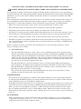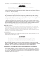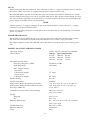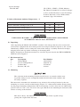
1
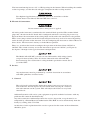
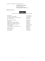
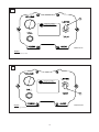
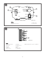
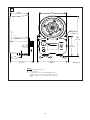
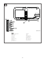
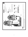
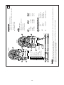
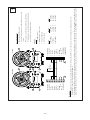
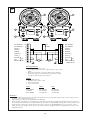
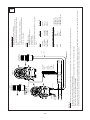
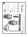
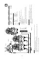
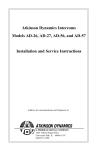
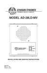
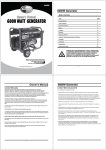
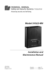
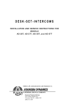
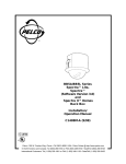
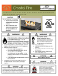
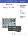
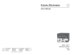
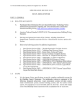
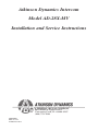
Atkinson Dynamics Intercom
Model AD-28X-MV
Installation and Service Instructions
2645 Federal Signal Drive
University Park, IL 60484-3167
(888) 751-1500
2561925B
REV. B 411
Printed in U.S.A.
INSTALLATION AND SERVICE INSTRUCTIONS FOR MODEL AD-28X-MV
SAFETY MESSAGE TO INSTALLERS, USERS AND MAINTENANCE PERSONNEL
It is important to follow all instructions shipped with this product. This device is to be installed by a
trained electrician who is thoroughly familiar with the National Electrical Code and will follow NEC
Guidelines as well as local codes. Marine installations shall be in accordance with Title 46, CFR,
Parts 110‑113.
The selection of the mounting location for the device, its controls and the routing of the wiring is to
be accomplished under the direction of the facilities engineer and the safety engineer. In addition,
listed below are some other important safety instructions and precautions you should follow:
• This is not a Listed emergency safety device and is not intended to be used as such.
• Read and understand all instructions before installing or operating this equipment.
• Disconnect power before connecting or doing any maintenance on this intercom.
• All effective warning speakers produce loud sounds which may cause in certain situations, perma‑
nent hearing loss. You should take appropriate precautions such as wearing hearing protection.
• After testing is complete, provide a copy of this instruction sheet to all operating personnel.
• Establish a procedure to routinely check the intercom installation for integrity and proper opera‑
tion. Any maintenance must be performed by a trained electrician in accordance with NEC guide‑
lines and local codes.
Failure to follow all safety precautions and instructions may result in property damage, serious
injury, or death to you or others.
A. General Features.
The AD-28X-MV intercom is a heavy duty, 2-way, communications device designed for in‑
dustrial applications. Nominal operating voltages include 120/240VAC, 50/60Hz and 24VDC.
Voltage changes for the 120/240VAC are internally switch selectable and the AC line is fused
with a 1/2 amp 250 volt type GMC fuse. The unit also offers transformer isolated audio inputs
and internally selectable Master or Slave mode configurations. A call button with remote call
dry contacts is also factory supplied in the unit.
The AD-28X-MV has a Type 4X enclosure and is a UL Listed Type NM (non-monitored)
signal appliance and Marine signal appliance for indoor or outdoor use and is CSA Certified.
The AD-28X-MV is additionally Listed for Class I, Groups A, B, C and D, Division 2; Class
II, Groups F and G, Division 2; and Class III.
Wire all circuits connected to the AD-28X-MV Intercom using Class I, Division 2 wiring
methods specified in Article 501-4 (b) of the NEC.
MASTER MODE:
The intercom can be configured as a Master unit (Push-to-Talk) or a Slave unit (Push-to-Listen)
by changing the MAS/SLA jumper (J2) on the printed circuit board (see Figure 6). The intercom
comes from the factory set in the Master (MAS) mode.
In the Master mode the intercom acts as an amplifier, constantly broadcasting over its speaker any
signal that it receives on the signal lines. Holding down the Listen/Talk switch changes the unit
from a speaker to a microphone (see Figure 1). The intercom will now transmit over the signal
lines to additional intercom(s) also set in the Master mode. When the switch is released it will
default back to the Listen or Speaker mode, allowing the user to receive any messages transmitted
back to it.
SLAVE MODE:
Some applications may require that the intercom constantly transmit (i.e. act as a microphone)
as opposed to constantly receive (i.e. act as a speaker). To accomplish this the intercom must be
configured in the Slave (Push-to-Listen) mode.
-1-
To configure an intercom in the Slave mode, perform the following steps:
Disconnect power to the intercom before any installation, maintenance, or
configuration changes are performed.
1. Move the J2 jumper on the P.C. board from the MAS to SLA position (see Figure 6). This can
be done using long nose pliers, pulling the jumper off the “MAS” and center position and placing
it on the “SLA” and center position.
2. An intercom configured in the Slave mode needs to have the Listen/Talk switch default to the
talk position on the cover plate (see Figure 2).
The second change required is to rotate the position of the Talk/Listen switch. This can be ac‑
complished by loosening the rubber boot covering the toggle switch enough to allow the toggle
switch to turn 180 degrees. The dimple on the locking ring must seat itself in the locating hole
(see Figure 3). The rubber boot is then tightened up against the cover plate with the toggle switch
leaning to the talk position, as shown in Figure 2.
3. The third change involves the interconnect wiring. When a unit is placed in the Slave mode it
defaults to the Talk or transmit position. When hooked to a Master unit it is necessary to override
the Slave unit in order for the Master unit to be able to transmit. The #6 pin (remote control) on
both terminal blocks (see Figure 4) must be connected between the Master and the Slave unit.
Figures 7 to 13 contain wiring diagrams of typical intercom configurations.
REMOTE CONTROL:
Remote control is used to change the operation mode of a remote intercom from listen to talk
or from talk to listen upon activation of a local intercom. The wiring diagram section illustrates
Master/Slave Installation and Using Foot Switches Diagrams. (See figures 9, 10, and 12).
Normally open foot switches can also be connected to the Remote Control line in order to allow
“hands free” operation of the listen/talk functions.
CALL BUTTON:
Depressing the call button sends a 1 kHz tone onto the signal lines. All units listening to the line
will then broadcast this signal as a call.
The call signal is substantially louder than normal voice messages being car‑
ried on the line. Do not depress the call switch while carrying on a conversa‑
tion with someone on the system. This will subject the listener to very loud
sound levels.
The volume of the call signal is affected by the volume control on the receiving unit, so if the
volume is turned all the way down at a receiving station, the call signal will not be heard. To avoid
this problem, the call dry contacts can be utilized to drive an external signalling device.
CALL BUTTON ACTUATED DRY CONTACTS FOR OPERATING AN EXTERNAL
DEVICE:
Depressing the call button also closes a normally open dry contact rated at 0.5 A at 125 Vac or
1.25 A at 24 Vdc. This contact can be used to trigger a remote sounder or light in order to accent
the call feature. The wiring diagram illustrates how an external light or horn can be wired in to
augment the call tone. (See Figure 11.)
-2-
24 Vdc:
When connecting the intercom to 24 Vdc, either the positive (+) supply conductor must be fused at
the source with a 1/2 A fuse or a power-limited power source must be used.
The AD-28X-MV is capable of sending DC power to another unit which is mounted in a remote
location without local power. 24 Vdc is available from pins 4 and 5 of the terminal block. It can be
run along with the signal lines to an intercom in a remote location. Only one unit should share the
power supply of another unit in any installation.
NOTE
Connect positive (+) supply conductor to pin #4 of terminal block. Connect negative (-) supply
connector to pin #5 of terminal block.
Figure 7 in the wiring diagrams section shows how two intercoms can be hooked up if no remote
power is available.
SURGE PROTECTION:
Metal Oxide Varistor (MOV) devices are used to protect the audio lines and the remote control
line. The intercom must have Earth Ground terminated to it to ensure surge protection.
The output amplifier of the AD-28X-MV offers full short circuit protection and overheat protec‑
tion.
MODEL AD-28X-MV SPECIFICATIONS
Operating Voltage
Current Draw
Amplifier Specifications
Frequency Response (-6dB)
Input Impedance
Max. Output Voltage
Sine Wave:
Unbalanced Output
Square Wave:
Unbalanced Output
Speaker Rating
Speaker Impedance
Temperature Range for Ordinary Locations
Temperature Range for Hazardous Locations
Fuse Type GMC-1/2
Call Button Actuated Dry Contact Rating
Weight
Shipping
Net
Housing Dimensions
Conduit Entrances
Housing Material
Color
24Vdc, 120 Vac and 240 Vac 50/60 Hz
Voltage OperatingStandby
24 Vdc 260 mA 62 mA
120 Vac 163 mA 70 mA
240 Vac 82 mA
35 mA
150 Hz to 12 kHz
3400 ohms
7.5 Vrms
9.5 Vrms
30 watts
16 ohms
–31° F to +150° F (–35° C to +66° C)
+41° F to +149° F (+5° C to +65° C)
1/2 A, 250 V
500 mA at 125 Vac
1.25 A @ 24 Vdc
10 lb, 11 oz
9 lb, 4 oz
6.5” (16.5 cm) W x 9.88" (25.1 cm) H x
3.88" (9.9 cm) D
Dual 1/2"-14 IPS
Aluminum
Gray
-3-
Agency Listings
AD-28X-MV
UL (UJPX), (UJPX7), (UXPL, Marine) For indoor or outdoor use in Class I, Groups
A, B, C and D, Division 2; Class II, Groups
F and G, Division 2; Class III hazardous
locations; Type 4X enclosure.
T-Code at Maximum Ambient Temperature, °C
Hazardous Location
40° C
65° C
Class I, Division 2, Groups A, B, C, D
T6
T5
Class II, Division 2, Groups F, G
T6
T5
Class III
T6
T5
EXPLOSION HAZARD – SUBSTITUTION OF COMPONENTS MAY IMPAIR
SUITABILITY FOR CLASS I, DIVISION 2.
B. Unpacking.
After unpacking the Model AD-28X-MV, examine it for damage that may have occurred in
transit. If the equipment has been damaged, do not attempt to install or operate it, file a claim
immediately with the carrier stating the extent of the damage. Carefully check all envelopes,
shipping labels and tags before removing or destroying them.
Before attempting to install the intercom, be sure that all parts listed in the KIT CONTENTS
LIST have been supplied.
C. Kit Contents List.
Qty.
1
4
4
1
Description
Wiring Block
Screws, Phillips Head
Lockwashers Resistor, 1K, 1W
Part Number
140A326-01
7000478-10
7074A010
101216
D. Mounting.
The selection of the mounting location for the device, its controls and the rout‑
ing of the wiring is to be accomplished under the direction of the facilities and
the safety engineer.
The intercom is intended to be mounted on any relatively flat and rigid surface by the two
mounting ears on the exterior of the housing. Figure 5 is a dimensional outline drawing show‑
ing the proper mounting configuration. The two mounting ears have slots for 3/8" (M10) bolts
spaced 5-5/8" to 5-7/8" (14.3 cm to 14.9 cm) apart. Hardware for mounting the intercom to the
surface is left up to the installer.
This unit is heavy and should be mounted on a rigid surface capable of sup‑
porting the weight of the intercom.
-4-
The intercom housing has two 1/2”-14 IPS openings in the bottom. When installing the conduit
to these openings, seal the threads with pipe compound or other sealing material.
For shipboard applications, installations shall be in accordance with the
United States Coast Guard, Title 46 CRF, Parts 110‑113.
E. Electrical Connections.
Do not connect wires when power is applied.
All wiring to the intercom is terminated to the terminal block provided. The terminal block
plugs into a header on the PC board and is configured such that it can only plug in one way.
Figure 6 shows the orientation of the wiring block and describes the function of each position.
There is one jumper shown on the PC board in Figure 6 that may need to be moved depending
on the desired operation of the intercom. J2 is for configuring the intercom as either a Master or
Slave device. The intercom is factory set in the Master position.
There is a switch on the board to configure the operation of the board from 120VAC to
240VAC. The switch is factory set for the intercom to operate on 120VAC (see Figure 6).
See figures 7 through 13 for typical intercom configurations.
The Model AD-28X-MV’s circuits are not nonincendive field wiring circuits
except for foot switches. Wire all circuits connected to the AD-28X-MV
Intercom using Class I, Division 2 wiring methods specified in Article 501-4
(b) of the NEC.
F. Service.
Any maintenance must be performed by a trained electrician in accordance
with NEC guidelines and local codes.
1. General.
The call signal is substantially louder than normal voice messages being car‑
ried on the line. Do not depress the call switch while carrying on a conversa‑
tion with someone on the system. This will subject the listener to very loud
sound levels.
Atkinson Dynamics will service your equipment or provide technical assistance with any
problems that cannot be handled locally.
Any units returned to Atkinson Dynamics for service, inspection, or repair must be ac‑
companied by a Return Material Authorization. This R.M.A can be obtained only from the
factory by calling (888) 751-1500.
At this time a brief explanation of the service requested or the nature of the malfunction,
should be given.
-5-
Address all communications and shipments to:
ATKINSON DYNAMICS
Service Department
2645 Federal Signal Drive
University Park, IL 60484-3167
2. Replacement Parts.
Replace fuse with GMC-1/2 only. DO NOT substitute.
Description
PC Board, AD-28X-MV
Kit, potentiometer with on/off switch
Kit, toggle switch
Kit, push button switch
Knob, Pot
Rubber Boot (Toggle Switch)
Rubber Boot (Pushbutton Switch)
Rubber Boot (Volume Control)
Terminal Block
AD-28X-MV Speaker/Housing Assy.
Cover Gasket
Resistor, 1K, 1W
Fuse, GMC-1/2
Mini-jumpers
Part Number
K2001915-02
K8590236
K8590298
K8590241
K141A129
K288801
K288697
K288A542A
K140A326-01
K8590217
K8590013
K101216
K148A155
K139A209
-6-
1
A
ATKINSON DYNAMICS
A FEDERAL SIGNAL COMPANY
UNIVERSITY PARK, IL USA
290A4725-01
English
A. Push down to talk
2
ATKINSON DYNAMICS
A FEDERAL SIGNAL COMPANY
UNIVERSITY PARK, IL USA
A
290A4725-02
English
A. Push up to listen
-7-
3
A
B
C
(ORANGE)
(YELLOW)
(BLACK)
(GRAY)
(BLACK)
(BLACK)
D
(BROWN)
BACK VIEW
290A4725-03
English
A. Dimple
C. Volume control
B. Listen/talk toggle switch
D. Call push button
4
A
10
B
C
9
8
D
7
6
E
F
5
4
G
H
I
3
2
1
L
J
K
290A4725-04
English
A. Terminal block pinout
G. Ground
B. Dry contact
H. 24VDC in/out (+)
C. For call
I. Neutral
D. Audio (-)
J. Hot
E. Audio (+)
K. Earth ground
F. Remote control
L. 120/240VAC in
NOTE: Terminal Block accepts 10 - 22 AWG wire.
-8-
5
3.88"
(9.9 cm)
5.68"
(14.6 cm)
∅ .41
(1 cm) WIDE
2 HOLES
9.88"
(25.1 cm)
ATKINSON DYNAMICS
A FEDERAL SIGNAL COMPANY
UNIVERSITY PARK, IL USA
A
C
2.38"
(6.1 cm)
6.50"
(16.5 cm)
5.0"
(12.7 cm)
English
A. 1/2-14 pipe thread 2 places
B. Audio (Class 2)
C. AC input (Class 1) or DC Input/Output (Class 2)
Positive supply conductor must be fused at source
with 1/2 A fuse or a power-limited source must be
used.
-9-
4.84"
(12.3 cm)
B
290A4725-05
6
2001915 - 02
J1
J5
J2
10
B
9
8
1
BAL
UNB
J6
O
E
F
G
H
I
3
2
J4
M
D
5
4
J3
N
C
7
6
250V
J7
MAS
SLA
240VAC 120VAC 1/2A
A
F1
L
J
K
290A4725-06
English
A. Terminal block pinout
I. Neutral
B. Dry contact
J. Hot
C. For call
K. Earth ground
D. Audio (-)
L. 120/240VAC‑in
E. Audio (+)
M. Master slave
F. Remote control
N. To control panel
G. Ground
O. Speaker plug
H. 24VDC in/out
-10-
-11-
WHT
GRN
AUDIO (+)
REMOTE
GROUND (-)
24VDC (+)
NEUTRAL
HOT
EARTH GROUND
7
6
5
4
3
2
1
(+) DC POWER
COMMON
AUDIO
AUDIO (-)
8
5
FOR CALL
9
AC
10 DRY CONTACT
ATKINSON DYNAMICS
2
3
1WATT
1K
BLK
WHT
GRN
ATKINSON DYNAMICS
REMOTE B
290A4725-07
3
1
AD-28X-MV
240V 50/60Hz
+DC Power
Common
BLK
WHT
--
AD-56-1
--
Remote B
12/24V Models
12/24V Models
POWER CONNECTIONS (Remote B):
AD-28X-MV
AD-28X-MV
Remote A
22-30VDC
120V 50/60Hz
Power
“earth” ground. Ground chassis of DC unit to ground.
electrically noisy areas. Ground one end of the shield to
5. 3-conductor/16-22 gauge cable. Use shielded cable in
4. “Call” Tone Switch
3. Talk/Listen Switch
2. Off/On/Speaker Volume Control
1. Speaker/Microphone
NOTES:
Release talk switch to listen.
speak into the speaker/microphone.
• To talk to other stations, press the talk/listen switch and
• When one talks, all intercoms will hear.
Operating Principle:
Reminders:
• Before installing remote intercoms, precautions should be taken to prevent feedback between two or more remotes in close proximity and acoustically reflective areas.
• 16–20 gauge low voltage audio cable. Twisted pair not required.
• Shielded audio cable not required unless operating in high electromagnetic fields. Ground one end of the shield to earth ground.
• Audio and power cables are not supplied with AD-28X-MV.
BLK
4
2
1
REMOTE A
7
-12-
REMOTE
GROUND (-)
24VDC (+)
NEUTRAL
HOT
EARTH GROUND
6
5
4
3
2
1
WHT
4
2
3
*
BLK
WHT
GRN
SEE POWER
*CONNECTIONS
1WATT
1K
AUDIO (+)
7
BLK
AUDIO (-)
8
AC
FOR CALL
9
10 DRY CONTACT
ATKINSON DYNAMICS
ATKINSON DYNAMICS
REMOTE B
290A4725-08
WHT
TO OTHER
INTERCOMS
BLK
3
1
AD-28X-MV
Common
Neutral
Earth Ground
GRN
HOT
+DC Power
WHT
BLK
AD-57A
AD-56A
AD-27A
AD-26A
Remote B
120/240V Models only
120/240V Models
12/24V Models
120/240V Models
12/24V Models
POWER CONNECTIONS (Remote B):
AD-28X-MV
AD-28X-MV
120V 50/60Hz
240V 50/60Hz
--
12-18VDC
22-30VDC
Remote A
Power
4. “Call” Tone Switch
3. Talk/Listen Switch
2. Off/On/Speaker Volume Control
1. Speaker/Microphone
NOTES:
Release talk switch to listen.
the speaker/microphone.
• To talk to other stations, press the talk/listen switch and speak into
• When one talks, all intercoms will hear.
Operating Principle:
Reminders:
• Before installing remote intercoms, precautions should be taken to prevent feedback between two or more remotes in close proximity and acoustically reflective areas.
• 16–20 gauge low voltage audio cable. Twisted pair not required.
• Shielded audio cable not required unless operating in high electromagnetic fields. Ground one end of the shield to earth ground.
• Audio and power cables are not supplied with AD-28X-MV.
AUDIO
LINE
4
2
1
REMOTE A
8
-13-
ATKINSON DYNAMICS
4
3
5
4
3
GROUND (-)
24VDC (+)
NEUTRAL
AC
5
6
REMOTE
3
1
1
2
8
290A4725-09
EARTH GROUND
HOT
NEUTRAL
24VDC (+)
GROUND (-)
REMOTE
AUDIO (+)
AC
DRY CONTACT
AUDIO (-)
240V 50/60Hz
AD-28X-MV
AD-28X-MV
AD-28X-MV
120V 50/60Hz
22-30VDC
Master Power
4. “Call” Tone Switch
3. Press-to-talk Switch
2. Off/On/Speaker volume control
1. Speaker/Microphone
NOTES:
microphone. Release talk switch to listen.
AD-28X-MV
AD-28X-MV
AD-28X-MV
Slave
• To talk into master, press talk switch and speak into speaker/
• When any master talks, slave hears. Other masters will hear.
switch.
• Slave talks to master hands-free, without having to press a talk
• Masters normally listen to slave.
Operating Principle:
Reminders:
• Before installing remote intercoms, precautions should be taken to prevent feedback between two or more remotes in close proximity and acoustically reflective areas.
• Audio and power cables are not supplied with AD-28X-MV.
• In this installation the Master is constantly broadcasting audio from the Slave. Pushing the listen/talk switch on either unit forces the Slave into the listen mode and the Master into the
talk mode. The MAS/SLA jumper J2, located on the P.C. board inside the Slave, must be placed in the SLA mode for this operation. See SLAVE MODE on page 2 and figures 2 and 6.
EARTH GROUND
1
2
6
7
AUDIO (+)
AC
7
8
9
9
HOT
SLAVE
10 DRY CONTACT
DRY CONTACT
1K
1 WATT
ATKINSON DYNAMICS
A FEDERAL SIGNAL COMPANY
UNIVERSITY PARK, IL USA
AUDIO (-)
4
3
10
AC
A FEDERAL SIGNAL COMPANY
UNIVERSITY PARK, IL USA
DRY CONTACT
4
2
1
2
MASTER
9
MASTER
10
SLAVE
1
1
2
2
3
ATKINSON DYNAMICS
3
ATKINSON DYNAMICS
A FEDERAL SIGNAL COMPANY
UNIVERSITY PARK, IL USA
A FEDERAL SIGNAL COMPANY
UNIVERSITY PARK, IL USA
4
4
DRY CONTACT
10
DRY CONTACT
9
9
DRY CONTACT
AUDIO (-)
8
8
AUDIO (-)
AUDIO (+)
7
7
AUDIO (+)
REMOTE
6
6
REMOTE
GROUND (-)
5
5
GROUND (-)
24VDC (+)
4
4
24VDC (+)
NEUTRAL
3
3
NEUTRAL
2
HOT
1
EARTH GROUND
HOT
AC
EARTH GROUND
10 DRY CONTACT
1K
1 WATT
AC
2
AC
FOOT SWITCH
N.O.
1
FOOT SWITCH
N.O.
AC
290A4725-10
Operating Principle:
• Masters normally listen to slave.
• Slave talks to master hands-free, without having to press a talk
switch.
• When any master talks, slave hears. Other masters will hear.
• To talk into master, press talk switch and speak into speaker/
microphone. Release talk switch to listen.
NOTES:
1. Speaker/Microphone
2. Off/On/Speaker volume control
3. Press-to-talk Switch
4. “Call” Tone Switch
Power
Master Slave
120V 50/60Hz
22-30VDC
240V 50/60Hz
AD-28X-MV
AD-28X-MV
AD-28X-MV
AD-28X-MV
AD-28X-MV
AD-28X-MV
Reminders:
• Before installing remote intercoms, precautions should be taken to prevent feedback between two or more remotes in close
proximity and acoustically reflective areas.
• Audio and power cables are not supplied with AD-28X-MV.
• In this installation the Master is constantly broadcasting audio from the Slave. Pushing the listen/talk switch on either unit
forces the Slave into the listen mode and the Master into the talk mode. The MAS/SLA jumper J2, located on the P.C. board
inside the Slave, must be placed in the SLA mode for this operation. See SLAVE MODE on page 2 and figures 2 and 6.
• Using normally open, simple contact closure foot switches (customer supplied) allows for total hands-free operation of the
listen/talk functions.
-14-
-15-
AUDIO
LINE
REMOTE B
POWER
GRN
RED
WHT
BLK
AUDIO CABLE
3
1
1WATT
1K
4
2
AUDIO
LINE
ATKINSON DYNAMICS
REMOTE A
GROUND (-)
24VDC (+)
NEUTRAL
HOT
EARTH GROUND
5
4
3
2
1
AC
REMOTE
6
AUDIO (-)
AUDIO (+)
FOR CALL
8
5
7
9
10 DRY CONTACT
3
1
TO OTHER
INTERCOMS
290A4725-11
+ POWER
- POWER
AUXILIARY
SIGNALING DEVICE
-- AD-28X-MV
AD-28X-MV
AD-28X-MV
Remote A POWER CONNECTIONS (Remote B):
BLK
+DC Power
HOT
WHT
Common
Neutral
GRN
Earth Ground
12-18VDC
120V 50/60Hz
22-30VDC
240V 50/60Hz
Power
12/24V Models
120/240V Models
12/24V Models
120/240V Models
120/240V Models only
AD-26-3
AD-27-3
AD-56-3
AD-57-3
Remote B
NOTES:
1. Speaker/Microphone
2. Off/On/Speaker Volume Control
3. Listen/Talk Switch
4. “Call” Tone Switch
5. Customer-Supplied Auxiliary Signaling Device (e.g., strobe
light)
Operating Principle:
• When one talks, all intercoms will hear.
• To talk to other stations, press the talk/listen switch and
speak into the speaker/microphone. Release talk switch to
listen.
• Pressing the call button on remote A or B provides a
contact closure for an attention-getting auxiliary signaling
device, e.g. a strobe light.
Reminders:
• Before installing remote intercoms, precautions should be taken to prevent feedback between two or more remotes in close proximity and acoustically reflective areas.
• 16–20 gauge low voltage audio cable. Twisted pair not required.
• Shielded audio cable not required unless operating in high electromagnetic fields. Ground one end of the shield to earth ground.
• Audio and power cables are not supplied with AD-28X-MV.
• The dry contacts can be used to switch an auxiliary audible or visual signaling device when the call button is depressed. The maximum ratings for the dry contacts are 0.5 amps @ 125VAC and 1.25 amps
@ 24VDC. This method assures a call is received even when the volume on one of the intercoms is turned all the way down.
*
BLK
WHT
GRN
POWER
* SEE
CONNECTIONS
4
2
5
AUXILIARY
SIGNALING DEVICE
11
-16-
MASTER B
GRN 1
3
1
BLK 3
1 WATT
1K
ATKINSON DYNAMICS
*
BLK
*
BLK
WHT
GRN
BLK
WHT
GRN
WHT 2
*
2
SEE POWER
CONNECTIONS
6
MASTER DESK SET A
WHT
GRN
7
4
2
CONTROL
COMMON
AUDIO
AC
EARTH GROUND
24VDC (+)
4
HOT
GROUND (-)
5
NEUTRAL
REMOTE
6
1
AUDIO (+)
7
2
AUDIO (-)
8
3
1
3
FOR CALL
9
10 DRY CONTACT
BLK 3
WHT 2
GRN 1
ATKINSON DYNAMICS
SLAVE
290A4725-12
Reminders:
• Before installing remote intercoms, precautions should be taken to prevent feedback between two or more remotes in close proxim‑
ity and acoustically reflective areas.
• Audio and power cables are not supplied with AD-28X-MV.
• In this installation the Masters are constantly broadcasting audio from the Slave. Pushing the listen/talk switch on any unit forces
the Slave into the listen mode and the Master into the talk mode. The MAS/SLA jumper J2, located on the P.C. Board inside the
Slave, must be placed in the SLA mode for this operation See SLAVE MODE on page 2 and figures 2 and 6.
5
Master A
AD-26CT
AD-27CT
--
--
Master B
AD-26C
AD-27C
AD-56C
AD-57C
Slave
-AD-28X-MV
AD-28X-MV
AD-28X-MV
POWER CONNECTIONS (MASTER A & B):
BLK
+DC Power
12/24V Models
HOT
120/240V Models
WHT
Common
12/24V Models
Neutral
120/240V Models
GRN
Earth Ground
120/240V Models only
Power
12–18VDC
120V 50/60Hz
22-30VDC
240V 50/60Hz
NOTES:
1. Speaker/Microphone
2. Off/On/Speaker volume control
3. Press-to-talk Switch
4. “Call” Tone Switch
5. Desk Set speaker (microphone is mounted on hand‑
set)
6. Desk Set speaker volume control
7. Handset earpiece volume control (mounted on back
of case)
Operating Principle:
• Masters normally listen to slave.
• Slave talks to master hands-free, without having to
press a talk switch.
• When any master talks, slave hears. Other masters
will hear.
• To talk into master, press talk switch and speak into
speaker/microphone. Release talk switch to listen.
12
-17-
BLK
WHT
GRN
REMOTE B
2
REMOTE A
ATKINSON DYNAMICS
COMMON
8
AUDIO
3
BLK
WHT
GRN
WHT
BLK
*
6
5
4
BLK
WHT
GRN
*
WHT
BLK
ATKINSON DYNAMICS
REMOTE C
POWER
* SEE
CONNECTIONS
6
7
4
5
BLK
WHT
24VDC (+)
NEUTRAL
HOT
EARTH GROUND
3
2
1
290A4725-13
GROUND (-)
4
AC
REMOTE
5
AUDIO (+)
6
4
6
AUDIO (-)
7
FOR CALL
8
9
10 DRY CONTACT
ATKINSON DYNAMICS
REMOTE D
REMOTE A
AD-26T
AD-27T
AD-57T
AD-56T
REMOTES B & C
AD-26
AD-27
AD-57
AD-56
REMOTE D
AD-28X-MV
AD-28X-MV
AD-28X-MV
Operating Principle:
1. When one intercom talks, all of the intercoms will hear.
2. For Remotes B, C, or D to talk to other stations, press the talk/listen switch and
speak into the speaker/microphone. Release talk switch to listen.
3. For Remote A to talk to other stations, press PTT‑button on handset and talk into
handset microphone.
NOTES:
1. Desk Set speaker (microphone is mounted on handset)
2. Desk Set speaker volume control
3. Handset earpiece volume control (mounted on back of case)
4. Speaker/Microphone
5. Off/On/Speaker volume control
6. Talk/Listen switch
7. “Call” Tone Switch
8. 3-conductor/16-22gauge cable. Use shielded cable in electrically noisy
areas. Ground one end of the shield to “earth” ground. Ground chassis of
DC unit to ground.
POWER CONNECTIONS (Remote A, B, & C):
BLK
+DC POWER
12/24V Models
HOT
120/240V Models
WHT
Common
12/24V Models
Neutral
120/240V Models
GRN
Earth Ground
120/240V Models only
POWER
12VDC
120V 50/60Hz
240V 50/60Hz
22-30VDC
Reminders:
• Before installing remote intercoms, precautions should be taken to prevent feedback between two or more remotes in
close proximity and acoustically reflective areas.
• 16–20 gauge low voltage audio cable. Twisted pair not required.
• Shielded audio cable not required unless operating in high electromagnetic fields. Ground one end of the shield to earth
ground.
• Audio and power cables are not supplied with AD-28X-MV.
*
5
1
13
blank page