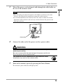
1
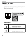
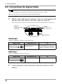
Instructions for Use
■User’s Manual
Important
Please read this User’s Manual carefully to familiarize yourself with safe and effective
usage. Please retain this manual for future reference.
Wichtig
Lesen Sie die dieses Benutzerhandbuch aufmerksam durch, um sich mit der sicheren
und effizienten Bedienung vertraut zu machen. Bewahren Sie dieses Handbuch zum
spateren Nachschlagen auf.
Important
Veuillez lire attentivement ce Manuel d’utilisation afin de vous familiariser avec ce
produit et de l’utiliser efficacement et en toute securite. Veuillez conserver ce manuel
pour reference ulterieure.
重要
请仔细阅读用户手册,掌握如何安全、有效地使用本产品。
请保留本手册,以备日后参考。
重要
ご使用前には必ずこの取扱説明書をよくお読みになり、正しくお使いください。
この取扱説明書は大切に保管してください。
For U.S.A. , Canada, etc. (rated 100-120 Vac) Only
FCC Declaration of Conformity
We, the Responsible Party
EIZO Inc.
5710 Warland Drive, Cypress, CA 90630
Phone: (562) 431-5011
declare that the product
Trade name: EIZO
Model: RadiForce RS110
is in conformity with Part 15 of the FCC Rules. Operation of this product is subject to the
following two conditions: (1) this device may not cause harmful interference, and (2) this device
must accept any interference received, including interference that may cause undesired
operation.
This equipment has been tested and found to comply with the limits for a Class B digital device,
pursuant to Part 15 of the FCC Rules. These limits are designed to provide reasonable protection
against harmful interference in a residential installation. This equipment generates, uses, and can
radiate radio frequency energy and, if not installed and used in accordance with the instructions, may
cause harmful interference to radio communications. However, there is no guarantee that interference
will not occur in a particular installation. If this equipment does cause harmful interference to radio
or television reception, which can be determined by turning the equipment off and on, the user is
encouraged to try to correct the interference by one or more of the following measures.
* Reorient or relocate the receiving antenna.
* Increase the separation between the equipment and receiver.
* Connect the equipment into an outlet on a circuit different from that to which the receiver is
connected.
* Consult the dealer or an experienced radio/TV technician for help.
Changes or modifications not expressly approved by the party responsible for compliance could void
the user’s authority to operate the equipment.
Note
Use the attached specified cable below or EIZO signal cable with this monitor so as to keep
interference within the limits of a Class B digital device.
- AC Cord
- Shielded Signal Cable (Enclosed)
Canadian Notice
This Class B digital apparatus complies with Canadian ICES-003.
Cet appareil numérique de le classe B est comforme à la norme NMB-003 du Canada.
■User’s Manual
It shall be assured that the final system is in compliance to IEC60601-1-1
requirements.
English
Instructions for Use
SAFETY SYMBOLS
SAFETY SYMBOLS
This manual uses the safety symbols below. They denote critical information. Please read them
carefully.
WARNING
Failure to abide by the information in a WARNING may result in serious
injury and can be life threatening.
CAUTION
Failure to abide by the information in a CAUTION may result in moderate
injury and/or property or product damage.
Indicates a prohibited action.
Indicates to ground for safety.
• Power supplied equipment can emit electromagnetic waves, that could influence, limit or
result in malfunction of the monitor. Install the equipment in a controlled environment, where
such effects are avoided.
• This is a monitor intended for use in a medical image system. It does not support the display
of mammography images for diagnosis.
• This product has been adjusted specifically for use in the region to which it was originally
shipped. If operated outside this region, the product may not perform as stated in the
specifications.
No part of this manual may be reproduced, stored in a retrieval system, or transmitted, in
any form or by any means, electronic, mechanical, or otherwise, without the prior written
permission of EIZO Corporation.
EIZO Corporation is under no obligation to hold any submitted material or information
confidential unless prior arrangements are made pursuant to EIZO Corporation's receipt of
said information. Although every effort has been made to ensure that this manual provides upto-date information, please note that EIZO monitor specifications are subject to change without
notice.
Macintosh and Mac OS are registered trademarks of Apple Inc.
Windows and Windows Vista are registered trademarks of Microsoft Corporation in the United
States and other countries.
VESA is a registered trademark or a trademark of Video Electronics Standards Association in
the United States and other countries.
EIZO, the EIZO Logo, ColorEdge, DuraVision, FlexScan, FORIS, RadiForce, RadiCS, RadiNET,
Raptor, and ScreenManager are registered trademarks of EIZO Corporation in Japan and other
countries.
All other company and product names are trademarks or registered trademarks of their
respective owners.
TABLE OF CONTENTS
TABLE OF CONTENTS
PRECAUTIONS..................................................................................................................... 4
Notice for this monitor................................................................................................................... 8
1. Introduction............................................................................................................................. 10
1-1. Features.................................................................................................................................... 10
1-2. Package Contents..................................................................................................................... 10
1-3. Controls and Connectors.......................................................................................................... 11
2. Cable Connection .................................................................................................................. 13
2-1. Before Connecting..................................................................................................................... 13
2-2. Connecting the signal cable...................................................................................................... 14
2-3. Connecting Two PCs to the Monitor ......................................................................................... 17
3. Adjustment and Settings......................................................................................................... 18
3-1. How to use the ScreenManager................................................................................................ 18
3-2. ScreenManager menu............................................................................................................... 19
3-3. Screen Adjustment (Analog Input)............................................................................................ 20
3-4. Color Adjustment....................................................................................................................... 23
3-5. Mode Preset Function <Setup>-<Mode Preset>....................................................................... 26
3-6. Power Saving Function <PowerManager>................................................................................ 26
3-7. Off Timer <Others>-<Off Timer>............................................................................................... 27
3-8. Adjustment Lock Function......................................................................................................... 28
3-9. Power Indicator Function <Others>-<Power Indicator >............................................................ 28
3-10. Setting the Orientation of the Menu........................................................................................ 29
3-11. Displaying Low Resolutions.................................................................................................... 29
4. Making Use of USB (Universal Serial Bus) ........................................................................... 31
5. How to attach the optional arm............................................................................................... 33
6. Troubleshooting....................................................................................................................... 34
7. Specifications.......................................................................................................................... 37
8. Glossary................................................................................................................................. 41
APPENDIX.....................................................................................................................................i
English
TABLE OF CONTENTS................................................................................................................ 3
PRECAUTIONS
PRECAUTIONS
IMPORTANT!
• This product has been adjusted specifically for use in the region to which it was originally
shipped.
If operated outside the region to which it was originally shipped, the product may not
perform as stated in the specifications.
• To ensure personal safety and proper maintenance, please read this section and the
caution statements on the unit (refer to the figure below).
[Location of the Caution Statements]
[Symbols on the unit]
Symbol
Location
This symbol indicates
Rear
Main Power Switch
Rear
Press to turn the monitor’s main power off.
Main Power Switch
Front
Control Panel
Press to turn the monitor’s main power on.
Power Button
Press to turn the monitor’s power on or off.
Rear
Name Plate
Rear
Alternating current
Rear
Caution
Refer to SAFETY SYMBOLS section in this manual.
Alerting electrical hazard
PRECAUTIONS
WARNING
English
If the unit begins to emit smoke, smells like something is burning, or makes strange
noises, disconnect all power connections immediately and contact your dealer for
advice.
Attempting to use a malfunctioning unit may result in fire, electric shock, or equipment
damage.
Do not open the cabinet or modify the unit.
Opening the cabinet or modifying the unit may result in fire, electric shock,
or burn.
Refer all servicing to qualified service personnel.
Do not attempt to service this product yourself as opening or removing covers may result in
fire, electric shock, or equipment damage.
Keep small objects or liquids away from the unit.
Small objects accidentally falling through the ventilation slots into the
cabinet or spillage into the cabinet may result in fire, electric shock, or
equipment damage. If an object or liquid falls/spills into the cabinet, unplug
the unit immediately. Have the unit checked by a qualified service engineer
before using it again.
Place the unit at the strong and stable place.
A unit placed on an inadequate surface may fall and result in injury or
equipment damage. If the unit falls, disconnect the power immediately and
ask your dealer for advice. Do not continue using a damaged unit. Using a
damaged unit may result in fire or electric shock.
Use the unit in an appropriate location.
Not doing so may result in fire, electric shock, or equipment damage.
• Do not place outdoors.
• Do not place in the transportation system (ship, aircraft, trains,
automobiles, etc.)
• Do not place in a dusty or humid environment.
• Do not place in a location where water is splashed on the screen
(bathroom, kitchen, etc.).
• Do not place in a location where the steam comes directly on the screen.
• Do not place near heat generating devices or a humidifier.
• Do not place in a location where the product is subject to direct sunlight.
• Do not place in an inflammable gas environment.
To avoid danger of suffocation, keep the plastic packing bags away from babies and
children.
Use the enclosed power cord and connect to the standard power outlet of your country.
Be sure to remain within the rated voltage of the power cord.
Not doing so may result in fire or electric shock.
Power supply: 100-120/200-240Vac 50/60Hz
PRECAUTIONS
WARNING
To disconnect the power cord, grasp the plug firmly and pull.
Tugging on the cord may damage and result in fire or electric shock.
The equipment must be connected to a grounded main outlet.
Failure to do so may result in fire or electric shock.
Use the correct voltage.
• The unit is designed for use with a specific voltage only. Connection to another voltage than
specified in this User’s Manual may cause fire, electric shock, or equipment damage.
Power supply: 100-120/200-240Vac 50/60Hz
• Do not overload your power circuit, as this may result in fire or electric shock.
Handle the power cord with care.
• Do not place the cord underneath the unit or other heavy objects.
• Do not pull on or tie the cord.
If the power cord becomes damaged, stop using it. Use of a damaged cord
may result in fire or electric shock.
For the electrical safety, do not connect or disconnect the power cord in the presence
of patients.
Never touch the plug and power cord if it begins to thunder.
Touching them may result in electric shock.
When attaching an arm stand, please refer to the user's manual of the arm stand and
install the unit securely.
Not doing so may cause the unit to become unattached, which may result in injury or
equipment damage. Before installation, make sure that desks, walls, and others an arm stand
is fixed on have adequate mechanical strength. When the unit is dropped, please ask your
dealer for advice. Do not continue using a damaged unit. Using a damaged unit may result in
fire or electric shock. When reattaching the tilt stand, please use the same screws and tighten
them securely.
Do not touch a damaged LCD panel directly with bare hands.
The liquid crystal that may leak from the panel is poisonous if it enters the
eyes or mouth.
If any part of the skin or body comes in direct contact with the panel,
please wash thoroughly. If some physical symptoms result, please consult
your doctor.
PRECAUTIONS
WARNING
English
Fluorescent backlight lamps contain mercury (the products that have LED backlight
lamps contain no mercury), dispose according to local, state or federal laws.
Exposure to elemental mercury can result in effects on the nervous system, including tremor,
memory loss, and headache.
CAUTION
Handle with care when carrying the unit.
Disconnect the power cord and cables when moving the unit. Moving the unit with the cord
attached is dangerous. It may result in injury.
Carry or place the unit according to the correct specified methods.
•When carrying the unit, grasp and hold firmly as shown in the illustration
below.
•Do not unpack or carry the unit only by a single person,since the large
size unit is so heavy.
Dropping the unit may result in injury or equipment damage.
Do not block the ventilation slots on the cabinet.
•Do not place any objects on the ventilation slots.
•Do not install the unit in a closed space.
•Do not use the unit laid down or upside down.
Blocking the ventilation slots prevents proper airflow and may result in fire,
electric shock, or equipment damage.
Do not touch the plug with wet hands.
Doing so may result in electrical shock.
Use an easily accessible power outlet.
This will ensure that you can disconnect the power quickly in case of a problem.
Periodically clean the area around the plug.
Dust, water, or oil on the plug may result in fire.
Unplug the unit before cleaning it.
Cleaning the unit while it is plugged into a power outlet may result in electric shock.
If you plan to leave the unit unused for an extended period, disconnect the power cord
from the wall socket after turning off the power switch for the safety and the power
conservation.
This product is only suitable for a patient environment, but not for contact with a
patient.
Notice for this monitor
Notice for this monitor
• This product is intended to be usedin displaying and viewing digitalimages for diagnosis
of X-ray orMRI, etc. by trained medicalpractitioners. It does not supportthe display of
mammography imagesfor diagnosis.
• This product has been adjusted specifically for use in the region to which it was originally
shipped. If the product is used outside the region, it may not operate as specified in the
specifications.
• This product may not be covered by warranty for uses other than those described in this
manual.
• The specifications noted in this manual are only applicable when the following are used:
- Power cords provided with the product
- Signal cables specified by us
• Only use optional products manufactured or specified by us with this product.
• As it takes about 30 minutes for the performance of electrical parts to stabilize, adjust the
monitor 30 minutes or more after the monitor power has been turned on.
• Monitors should be set to a lower brightness to reduce changes in luminosity caused by longterm use and maintain a stable display.
• When the screen image is changed after displaying the same image for extended periods of
time, an afterimage may appear. Use the screen saver or timer to avoid displaying the same
image for extended periods of time.
• Periodic cleaning is recommended to keep the monitor looking new and to prolong its
operation lifetime (Refer to “Cleaning” (page 9).)
• The screen may have defective pixels or a small number of light dots on the screen. This is
due to the characteristics of the panel itself, and is not a malfunction of the product.
• The backlight of the LCD panel has a fixed lifetime. When the screen becomes dark or begins
to flicker, please contact your dealer.
• Do not press on the panel or edge of the frame strongly, as this may result in display
malfunctions, such as interference patterns, etc. If pressure is continually applied to the panel,
it may deteriorate or damage your panel. (If the pressure marks remain on the panel, leave
the monitor with a black or white screen. The symptom may disappear.)
• Do not scratch or press on the panel with any sharp objects, as this may result in damage to
the panel. Do not attempt to brush with tissues as this may scratch the panel.
• When the monitor is cold and brought into a room or the room temperature goes up quickly,
dew condensation may occur on the interior and exterior surfaces of the monitor. In that case,
do not turn the monitor on. Instead wait until the dew condensation disappears, otherwise it
may cause some damage to the monitor.
Notice for this monitor
Cleaning
NOTE
English
•Chemicals such as alcohol and antiseptic solution may cause gloss variation, tarnishing,
and fading of the cabinet or panel, and also quality deterioration of the image.
•Never use any thinner, benzene, wax, and abrasive cleaner, which may damage the
cabinet or panel.
Tips
•The optional ScreenCleaner is recommended for cleaning the cabinet and panel surface.
If necessary, the stains on the cabinet and panel surface can be removed by moistening part
of a soft cloth with water.
To use the monitor comfortably
•An excessively dark or bright screen may affect your eyes. Adjust the brightness of the
monitor according to the environmental conditions.
•Staring at the monitor for a long time tires your eyes. Take a 10-minute rest every
hour.
1. Introduction
1. Introduction
Thank you very much for choosing an EIZO Color Monitor.
1-1. Features
•Dual inputs compliant (DVI-I and D-Sub mini 15 pin connectors)
•DVI (p.41) digital input (TMDS (p.42)) compliant
•Horizontal scan frequency Analog: 30 - 82 kHz
Digital: 30 - 65 kHz
•Vertical scan frequency
Analog: 49 - 86 Hz (1280 x 1024: 49 - 76 Hz)
Digital: 59 - 61 Hz (VGA text: 69 - 71 Hz)
•Frame synchronous mode
57.5 - 62.0 Hz supported
1M pixels (Landscape: 1280 × 1024 dots (H × V))
•Resolution
•CAL Switch function for selecting an optimal calibration mode (p. 23)
•Selectable DICOM (p. 41) Part 14 complied screen
•USB (Universal Serial Bus) hub support (p. 31)
•The quality control software “RadiCS LE” (for Windows) used to calibrate the
monitor is included (refer to the EIZO LCD Utility Disk).
•The utility software “ScreenManager Pro for Medical” (for Windows) to control the
monitor from a PC with mouse/keyboard is included (refer to the EIZO LCD Utility
Disk).
•The utility software “ToneCurve Tuning Utility” (for Windows), which can adjust the
tone setting of the monitor from the computer, is included (refer to the ToneCurve
Tuning Utility Disk).
•The height adjustable stand incorporated
•Slim bezel
•The Portrait display capability (rotate 90 degrees clockwise)
1-2. Package Contents
Please contact your local dealer for assistance if any of the listed items are missing or
damaged.
•LCD Monitor
•Power Cord
•Digital Signal Cable (DD300)
•EIZO USB Cable (UU300)
•EIZO LCD Utility Disk
•ToneCurve Tuning Utility Disk
•User’s Manual
•LIMITED WARRANTY
•Recycling Information
Tips
•Please retain the packing materials for future transport of the monitor.
10
1. Introduction
1-3. Controls and Connectors
English
Front
Main Power Switch
ScreenManager ®
main menu
CAL Switch menu
Control Panel
(1) (2) (3) (4)
(1)
(2)
(3)
Input Signal Selection
Button
Mode Button
(5)
(6) (7)
Switches input signals for display when two PCs are connected to
the monitor.
Displays the CAL Switch menu (p. 23).
(5)
Auto Adjustment Button Performs the function to adjust the screen automatically. (analog
input only)
Enter Button
Displays the ScreenManager menu, determines an item on the
menu screen, and saves values adjusted.
Control Buttons*1
Chooses an adjustment item or increases/decreases adjusted
(6)
(7)
(Left, Down, Up, Right) values for advanced adjustments using the ScreenManager menu.
(p. 18)
Power Button
Turns the power on or off.
Indicates monitor’s operation status
Power indicator*2
(4)
Blue:
Operational
Orange:
Power saving
Flashing orange slowly:
Power off (Main Power is on)
Off:
Main Power off
*1
When the monitor is oriented in the portrait position, these buttons can be changed to Up, Left, Right, and
Down.
*2
To disable the power indicator while the monitor is operational, see p. 28. For power indicator status when
using the “Off Timer,” see p.27.
11
1. Introduction
Rear
D-SUB
DVI
(8)
(10) (12)
(11) (13)
Power connector
(8)
(9)
Stand*3
Security lock slot
Used to adjust the height and angle of the monitor screen.
Allows for connection of a security cable.
(10)
(11)
(12)
(13)
Input signal connector
Input signal connector
USB port (Up)
USB port (Down)
This lock supports Kensington’s MicroSavere security system.
D-Sub mini 15 pin Connector (SIGNAL1)
DVI-I Connector (SIGNAL2)
Connects the USB cable in order to use the provided software.
Connects a peripheral USB device.
*3
12
(9)
The LCD monitor has the capability of the Portrait/Landscape display. (The panel pivots in the clockwise
direction 90°.)
The LCD monitor can be used with an optional arm stand by removing the stand. (p. 33)
2. Cable Connection
2. Cable Connection
Before connecting your monitor to the PC, change the display screen settings (resolution
(p.42) and frequency) in accordance with the charts below.
Tips
•When your computer and monitor support VESA DDC, the appropriate resolution and
the refresh rate are set just by plugging your display into the computer without any
manual settings.
Analog Input
Resolution
Mode
Frequency
Dot Clock
640 x 480
640 x 480
720 x 400
800 x 600
1024 x 768
1152 x 864
1280 x 960
1280 x 1024
VGA
VESA
VGA TEXT
VESA
VESA
VESA
VESA
VESA
60 Hz
~ 85 Hz
70 Hz
~ 85 Hz
~ 85 Hz
75 Hz
60 Hz
~ 75 Hz
135 MHz
(Max.)
Digital Input
Resolution
Mode
Frequency
Dot Clock
640 x 480
720 x 400
800 x 600
1024 x 768
1280 x 1024
VGA
VGA TEXT
VESA
VESA
VESA
60 Hz
70 Hz
60 Hz
60 Hz
60 Hz
108 MHz
(Max.)
13
English
2-1. Before Connecting
2. Cable Connection
2-2. Connecting the Signal Cable
NOTE
•Be sure that the power switches of both the PC and the monitor are OFF.
•Refer to the PC user's manual when connecting the monitor.
1
Plug the signal cable into the connector on the rear of the monitor and
the other end of the cable into the video connector on the PC.
After connecting, secure the cable connectors with the attached screw-in fasteners.
SIGNAL1
D-Sub mini 15 pin
Connector
SIGNAL2
DVI-I Connector
Power cord
Analog Input
Connect to SIGNAL1 (D-Sub 15 pin Connector).
Signal Cable
Connector on PC
Signal cable (MD-C87 optional) Video Output Connector /
D-Sub mini 15 pin
PC
• Standard graphics card
• Power Macintosh G3 (Blue &
White) / Power Mac G4 (VGA)
Digital Input
Connect to SIGNAL2 (DVI-I Connector).
Signal Cable
Signal cable (DD300 enclosed)
2
14
Connector on PC
PC
Video Output Connector / DVI • Exclusive graphics board (p. 39)
Connect the power cord to the power connector on the rear of the
monitor.
2. Cable Connection
3
Thread the power cord and signal cable through the cable holder on
the rear of the monitor stand.
English
NOTE
•When threading the cables through the cable holder, lead them to the cable
entrance side and pinch the projection to open the cable entrance.
•It is recommended that some slack be left in the cables to allow for smooth
adjustment of the monitor stand and easy rotation between the portrait and
landscape positions.
Cable holder
4
Connect the other end of the power cord to a power outlet.
WARNING
Use the enclosed power cord and connect to the standard power
outlet of your country.
Be sure to remain within the rated voltage of the power cord. Not doing so may result in fire or electric shock.
The equipment must be connected to a grounded main outlet.
Not doing so may result in fire or electric shock.
5
Turn on the monitor’s power by pressing the Power Button.
The monitor’s power indicator will light up blue.
15
2. Cable Connection
6
Turn on the PC’s power.
The image will appear.
If an image does not appear, refer to “6. Troubleshooting” (p. 34) for additional
advice.
Refer to “3-3. Screen Adjustment (In case of Analog Input Signal)” (p. 20) and
adjust the screen for analog input.
If using the monitor in the digital input signal, it displays the image correctly based
on its pre-setting data.
When finished, turn off the PC and the monitor.
Tips
•Adjust the brightness of the screen depending on the brightness of your
environment.
•Be sure to take adequate rests. A 10-minute rest period each hour is suggested.
7
When using the software “RadiCS LE” (for Windows),
“ScreenManager Pro for Medical” (for Windows) or “ToneCurve
Tuning Utility”, connect the monitor to an USB compliant Windows
computer (or other USB hub) with an USB cable.
Refer to “4. Making Use of USB (Universal Serial Bus)” (p. 31).
16
2. Cable Connection
2-3. Connecting Two PCs to the Monitor
Selecting the Active Input
The Input Signal Selection Button on the control panel can be used to select either Signal 1
or Signal 2 as the active input at any time. Every time the button is pressed, the input
changes. When the signal is switched, the active signal type (Signal 1 or 2/ Analog or
Digital) appears at the topright corner of the screen.
Input Signal Selection Button
The Priority Input Signal
This function is used to select which PC will have priority to control the monitor by
selecting <Input Priority> in the ScreenManager <Setup> menu (See p. 18 to use the
ScreenManager). In the case of only one signal being present at either input, the monitor
automatically detects and displays that signal.
SIGNAL2
DVI-I Connector
SIGNAL1
D-Sub mini 15 pin
Connector
Priority Setting
1
Performance
The input signal from “Signal 1” is displayed in the following cases.
Input from Signal 1 •When the monitor is turned on.
•When the PC for the “Signal 1” is turned on while displaying the image of
the “Signal 2”.
•When the PC for the “Signal 1” is recovered from the Power saving mode
while displaying the image of the “Signal 2”.
The input signal from “Signal 2” is displayed in the following cases.
2
Input from Signal 2 •When the monitor is turned on.
•When the PC for the “Signal 2” is turned on while displaying the image of
the “Signal 1”.
Manual
•When the PC for the “Signal 2” is recovered from the Power saving mode
while displaying the image of the “Signal 1”.
The monitor will not detect signals automatically in this mode. Select the
active input by pressing the Input Signal Selection Button on the monitor’s
control panel.
Tips
•When the “1” or “2” is selected, the power saving mode of the monitor activates only if
both PCs are in power saving mode.
17
English
Two PCs can be connected to the monitor through the Signal 1 and the Signal 2 on the
back of the monitor.
3. Adjustment and Settings
3. Adjustment and Settings
3-1. How to use the ScreenManager
Screen adjustments and settings can be performed with the ScreenManager (OSD) and
buttons of the monitor.
CAL Switch menu
ScreenManager
menu
Auto Adjustment Button
Mode Button
Control Buttons
Left, Down, Up, Right
Enter Button
Power Button
NOTE
•The ScreenManager menu and the CAL Switch menu cannot be displayed at the same
time.
1 .
Enter the ScreenManager.
Press the Enter Button once to display the main menu of the ScreenManager.
2 .
Making Adjustments and Settings.
(1)Select the desired sub menu icon using the Control Buttons and press the Enter
Button. The sub menu appears.
(2)Use the Control Buttons to select the desired setting icon and press the Enter
Button. The setting menu appears.
(3)Use the Control Buttons to make all required adjustments and press the Enter
Button to save the settings.
3 .
Exiting the ScreenManager.
(1)To return to the main menu, select the <Return> icon or press the Down Button
twice, followed by the Enter Button.
(2)To exit the ScreenManager, select the <Exit> icon or press the Down Button twice,
followed by the Enter Button.
Tips
•Double clicking the Enter Button also exits the ScreenManager menu.
18
3. Adjustment and Settings
3-2. ScreenManager menu
English
Using ScreenManager menu controls the screen adjustment and settings. Refer to the
“Explanation” column in the following table for each detailed functions.
Functions
The following table shows all the ScreenManager’s adjustment and setting menus.
“*” indicates adjustments of analog input only and “**” indicates digital input only.
Main menu
Setup
Sub menu
Mode Preset
Input Priority
Screen*
Color *1
PowerManager
Others
Clock
Phase
Position
Resolution
Range Adjustment
Signal Filter
Brightness
Temperature
Gamma
Saturation
Hue
Gain
6 Colors
Reset
DVI DMPM**
VESA DPMS*
Screen Size
Smoothing
Border Intensity
Off Timer
Menu Settings Menu Size
Menu Position
Menu Off Timer
Translucent
Orientation
Power Indicator
Reset
Information
Information
Explanation
3-5. Mode Preset Function <Setup><Mode Preset> (p. 26)
Select the priority input signal. (p. 17)
3-3. Screen Adjustment (Analog Input)
(p. 20)
3-4. Color Adjustment (p. 23)
3-6. Power Saving Function
<PowerManager> (p. 26)
3-11. Displaying Low Resolutions (p. 29)
Set the monitor’s off timer to on or off
(p. 27).
Change the size of the menu.
Adjust the menu position.
Set the menu displaying time.*2
Set the transparency of the background.
Change the orientation of the
ScreenManager for monitor's portrait
position.
Make non-light for blue lighting when
the screen is displayed(p. 28).
Return to the factory default
settings(p.38).
Review the ScreenManager’s settings,
model name, serial number and usage
time*3.
19
3. Adjustment and Settings
Main menu
Language
Sub menu
Explanation
Select the ScreenManager’s language.
English, German, French, Spanish,
Italian, Swedish, Chinese(Simplified),
Chinese(Traditional) and Japanese
*1
The adjustable functions depend on the selected CAL Switch mode. (p. 24)
*2
The display time of the CAL Switch menu can be adjusted.
*3
Due to factory inspection, the usage time may not be “0 hours” at time of shipping.
3-3. Screen Adjustment (Analog Input)
Screen adjustments for the LCD monitor should be used in suppressing screen flickering
and also for adjusting the screen to its proper position. It is also recommended to use the
ScreenManager function when first installing the display or whenever changing the system.
NOTE
•Allow the LCD monitor to stabilize for at least 30 minutes before making image
adjustments.
Adjustment Procedure
About how to use the ScreenManager, refer to p. 18.
1 .
Press the Auto Adjustment Button on the control panel.
The message “Your setting will be lost, if you press again now.” appears and
remains on the screen for 5 seconds. While the message is on the screen, press the
Auto Adjustment Button again to automatically adjust the clock, phase, screen
position and resolution. If you do not wish to do adjust the screen, do not press
the Auto Adjustment Button again.
NOTE
•The Auto Adjustment function is intended for use on the Macintosh and on ATcompatible PC running Windows. It may not work properly in either of the
following cases.
When running an AT-compatible PC on MS-DOS (Not windows). The
background color for the “wall paper” or “desktop” pattern is set to black.
• It cannot work correctly using with some graphics cards.
If the appropriate screen cannot be made by using the Auto Adjustment Button,
adjust the screen through the following procedures. If the appropriate screen can be
made, proceed to step 3.
20
3. Adjustment and Settings
2 .
Adjust the advanced setting by using <Screen> menu in the
ScreenManager.
(2) Horizontal flickering, blurring or bars appear on the screen.
Use the <Phase> (p. 41) adjustment.
Select the <Phase> and eliminate the horizontal flickering, blurring or bars by
using the Right and Left Buttons.
NOTE
•Horizontal bars may not completely disappear from the screen depending
on the PC.
(3) The screen position is incorrect.
Use the <Position> adjustment.
The correct displayed position of the monitor is decided because the number and
the position of the pixels are fixed. The <Position> adjustment moves the image to
the correct position.
Select <Position> and adjust the position of the upper left corner of the image by
using the Up, Down, Right and Left Buttons in order to align the screen.
If vertical bars of distortion appear after finishing the <Position> adjustment,
return to <Clock> adjustment and repeat the previously explained adjustment
procedure (“Clock”
“Phase”
“Position”).
21
English
(1) Vertical bars appear on the screen.
Use the <Clock> (p. 41) adjustment.
Select the “Clock” and eliminate the vertical bars by using the Right and Left of
the Control Buttons. Do not press the Control Buttons continuously, as the
adjustment value will change quickly and make it difficult to locate the most
suitable adjustment point.
If the horizontal flickering, blur or bars appear, proceed to “Phase” adjustment as
follows.
3. Adjustment and Settings
(4) Screen image is smaller or larger than the actual screen images.
Use the <Resolution> adjustment.
Adjustment is needed when the input signal resolution and the resolution now
being displayed are different.
Select <Resolution> and confirm if the resolution now being displayed is the
same as the input resolution. If it is not, adjust the vertical resolution using
the Up and Down Button and adjust the horizontal resolution using the Right
and Left Buttons.
Extra image is displayed due to excessive dots.
A part of image is cut due to short dots.
3 .
Adjust the output signal range (Dynamic Range) of the signal.
Use the <Range Adjustment> (p. 42) of <Screen> menu.
This controls the level of output signal range to display the whole color gradation
(256 colors).
[Procedure]
Press the Auto Adjustment Button on the control panel while displaying the
<Range Adjustment> menu to automatically adjust the range. The screen blanks
for a moment and adjusts the color range to display the whole color gradation of
the current output signal.
22
3. Adjustment and Settings
3-4. Color Adjustment
The most suitable display mode is available by pressing the Mode Button on the control
panel.
The <Brightness>, <Temperature>, and <Gamma> settings can be adjusted on the CAL
Switch menu.
CAL Switch Modes
Mode
1 - DICOM
2 - Custom
3 - CAL
4 - Text
*
Description
*
*
*
Used to display images in the DICOM mode
Used to adjust color setting preferences
Used for monitor calibration
Suitable for displaying text from word processing or spreadsheet software
All modes can be calibrated independently.
The mode name can also be changed using the calibration kit (RadiCS LE / see Optional, p. 39).
How to use the CAL Switch Function
[Entering the CAL Switch menu]
Press the Mode Button.
[Selecting the CAL Switch mode]
CAL Switch menu
CAL Switch mode
Brightness
Temperature
Gamma
Press the Mode Button while the CAL Switch menu is displayed.
Pressing Mode Button allows you to select the following mode.
1-DICOM
2-Custom
3-CAL
4-Text
1-DICOM
[Making color adjustments in CAL Switch mode]
1.Select the desired setting icon with the Up and Down Button.
2.Adjust the value of the selected item with the Left and Right Button.
[Closing the CAL Switch menu]
Press the Enter Button.
NOTE
•The ScreenManager menu and CAL Switch menu cannot be displayed at the same time.
•When switching between modes, the monitor can be set to display only the specified
modes, skipping any unnecessary modes (see p.26 3-5. Mode Preset Function <Setup><Mode Preset>).
•In some modes, <Temperature> and/or <Gamma> settings may be fixed at the default
values (p. 24).
•Detailed color settings for each mode can be adjusted in the <Color> menu of the
ScreenManager (p. 24).
23
English
Simple Adjustment [CAL Switch mode]
3. Adjustment and Settings
Advanced Adjustments[Adjustment menu]
The color settings for each CAL Switch mode can be adjusted and saved in the <Color>
menu of the ScreenManager.
Available settings
The settings available for adjustment and the icons displayed in the ScreenManager will
differ depending on which CAL Switch mode is selected. Refer to the following table as
needed.
“√”: Adjustable “-”: Fixed at the factory
Icons
Settings
1 - DICOM
CAL Switch Mode
3 - CAL
2 - Custom*2
4 - Text
Brightness*1
√
√
√
√
Temperature*1
-
√
-
√
Gamma*1
-
√
-
√
Saturation
-
√
-
√
Hue
-
√
-
√
Gain
-
√
-
-
6 colors
-
√
-
-
Reset
√
√
√
√
*1
These settings can also be adjusted on the CAL Switch menu (p. 23).
*2
When calibration is performed in this mode using the calibration kit (RadiCS LE / see Optional, p. 39), only the
brightness and reset settings can be adjusted.
NOTE
•Allow the monitor to warm up for at least 30 minutes before making color adjustments.
•The <Reset> setting restores the default color settings in the <Color> menu for the
selected CAL Switch mode.
•Because each monitor is subject to individual differences, colors may appear slightly
different, even for the same image, when several monitors are lined up side-by-side.
When aligning the color on several monitors, use visual judgment to fine-tuning the
settings.
24
3. Adjustment and Settings
Adjustment Contents
Menu
Description
Adjustable Range
Sets the brightness of the
screen
0~130%
Temperature (p. 42)
Sets the color temperature
6500 K~15000 K
in 500 Kincrements (including 9300 K).
English
Brightness
Tips
•The values shown in the Kelvin (K) are available only as reference.
•While color temperature is adjusted, <Gain> is adjusted
automatically according to the color temperature.
•When <Gain> is set, color temperature setting is disabled, and is
set to “OFF”.
•Setting the temperature under 6500 K or over 15000 K invalidates
the color temperature setting. (The color temperature setting turns
“OFF”.)
Gamma (p. 41)
Sets the gamma value
1.8~2.6
Saturation
To change the saturation
-100~100
Selecting the minimum level (-100)
makes the image monochrome.
NOTE
•The <Saturation> adjustment may cause undisplayable color tone.
Hue
Sets the hue value(for flesh
tones, etc.)
-100~100
NOTE
•The <Hue> adjustment may cause undisplayable color tone.
Gain (p. 42)
Sets the gain for each color (red, 0~100%
green, and blue)
By adjusting the red, green and blue
color tones for each mode, custom
colors can be defined. Display a white
or gray background image and adjust the
<Gain>.
Tips
•Values shown in percentages are meant only as a reference.
•The <Temperature> setting invalidates this setting. The <Gain>
setting varies with color temperature.
6 colors
Reset
Sets <Saturation> and <Hue> Hue : -100~100
for each color (red, yellow,
Saturation : -100~100
green, cyan, blue, and magenta)
Restores the default color
Select the <Reset>.
settings for the selected mode
25
3. Adjustment and Settings
3-5. Mode Preset Function <Setup>-<Mode Preset>
When CAL Switch mode is selected, the computer can be forced to display only specified
modes. Use this function when the display modes are restricted or when the display should
not be changed needlessly.
[How to set]
1.Select <Mode Preset> in the ScreenManager <Setup> menu.
2.Set each mode to “On” or “Off”.
NOTE
•You cannot disable all modes. Set one or more modes to “On”.
[How to cancel]
1.Select <Mode Preset> in the ScreenManager <Setup> menu.
2.Set the mode that you wish to display to “On”.
3-6. Power Saving Function <PowerManager>
The <PowerManager> menu in the ScreenManager enables to set the power saving.
NOTE
•Do your part to conserve energy, turn off the monitor when you finished using it.
Disconnecting the monitor from the power supply is recommended to save energy
completely.
•Even if the monitor is in a power saving mode, USB compliant devices function when
they are connected to the monitor’s USB (both the upstream and the downstream ports).
Therefore, power consumption of the monitor will change according to the connected
devices even if the monitor is in a power saving mode.
Digital input
This monitor complies with the “DVI DMPM” (p. 41).
[How to set]
1.Set the PC’s power saving settings.
2.Select “DVI DMPM” in the <PowerManager> menu.
[Power saving system]
PC
On
Power saving/ Off mode
Monitor
Operation
Power saving
Power Indicator
Blue
Orange
[Power Resumption Procedure]
Operate the mouse or keyboard to return to a normal screen.
Power on the PC to return a normal screen from the Off mode of the PC.
26
3. Adjustment and Settings
Analog Input
This monitor complies with the “VESA DPMS” (p. 42).
English
[How to set]
1.Set the PC’s power saving settings.
2.Select “VESA DPMS” in the <PowerManager> menu.
[Power saving system]
PC
Operation
Power saving
STAND-BY
SUSPEND
OFF
Monitor
Operation
Power saving
Power Indicator
Blue
Orange
[Power Resumption Procedure]
Operate the mouse or keyboard to return to a normal screen.
3-7. Off Timer <Others>-<Off Timer>
The off timer function causes the monitor to turn off automatically after a predetermined
amount of time has lapsed. This function was created to reduce the afterimages particular
to LCD monitors, which appear when the screen is left on for long periods without use.
[How to set]
1.Select <Off Timer> in the ScreenManager <Others> menu.
2.Select “Enable” and press the Right and Left Buttons to adjust the “On Period” (1 to 23
hours).
[Off timer system]
PC
Operating time (1H - 23H)
Last 15 min. in operating time
Operating time expired
Monitor
Operational
Advance Notice *1
Power off
Power Indicator
Blue
Flashing blue
Flashing orange slowly
*1Advance
notice (Power Indicator flashing blue) will be given 15 minutes before the monitor automatically
enters the “Power Off” mode. To delay entering the “Power Off” mode, press the Power Button during the
advance notice period. The monitor will continue to operate for an additional 90 minutes.
[Power Resumption Procedure]
Press the Power Button to return to a normal screen.
NOTE
•The off timer function works while the PowerManager is active, but there is no advance
notice before the monitor's power is turned off.
27
3. Adjustment and Settings
3-8. Adjustment Lock Function
Use the “Adjustment Lock” function to prevent any accidental changes.
Locked functions
• Display, adjustment, and setting of the ScreenManager
Unlocked function
• Brightness adjustments to the CAL Switch mode
• Selection of the CAL Switch mode with the Mode Button
• Input Signal Selection Button
[To lock]
1.Switch off the monitor’s power by the Power Button on the control panel.
2.Hold down the Auto Adjustment Button and turn the monitor's power on.
[To unlock]
1.Switch off the monitor’s power by the Power Button on the control panel.
2.Hold down the Auto Adjustment Button once again and turn the power back on.
NOTE
•The adjustment lock function may activate when calibration is performed with the
calibration kit (RadiCS LE / see Optional, p. 39). The monitor can be unlocked using the
same unlocking procedure described above.
3-9. Power Indicator Function <Others>-<Power Indicator >
Use the function to keep the power indicator without light while the monitor is operational.
(The power indicator is set by default to light when the power is turned on.)
[How to set]
1.Select <Power Indicator> in the ScreenManager <Others> menu.
2.Select “Disable”.
28
3. Adjustment and Settings
3-10. Setting the Orientation of the Menu
[Procedure]
1.Select <Orientation> in the ScreenManager <Others> menu.
2.Set the orientation to "Portrait".
3-11. Displaying Low Resolutions
With this function, low-resolution images, such as VGA 640x480, can be displayed at a
desired size. In addition, it is possible to adjust or set smoothing for such images and the
brightness for blank border areas.
Changing the Screen Size
[Procedure]
1.Select <Screen Size> in the ScreenManager <Others> menu.
2.Select the screen size with the Up and Down Buttons.
Menu
Explanation
Full Screen
Stretches the image to cover the full screen, regardless of the image's
resolution. Since the vertical resolution and the horizontal resolution are
enlarged at different rates, some images may appear distorted.
Enlarges the image on the screen, regardless of the image's resolution.
Since the vertical resolution and horizontal resolution are enlarged at
same rates, some horizontal or vertical image may disappear.
Displays the image at the actual Screen resolution.
Enlarged
Normal
Example: Displaying 1024 x 768
Full
Enlarged
Normal (Default Setting)
(1280×1024)
(1280×960)
(1024×768)
Smoothing the blurred texts
Image smoothing can be adjusted if text or lines appear blurred when the display is set to
“Full Screen” or “Enlarged” mode.
29
English
This function allows you to change the orientation of the ScreenManager when using the
monitor screen in vertical display position.
3. Adjustment and Settings
[Procedure]
1.Select < Smoothing> in the ScreenManager <Others> menu.
2.Select a suitable level of the smoothing from 1 to 5 (Soft to Sharp) with the Right and
Left Buttons.
NOTE
•Smoothing setting may not be required depending on the display resolution. (You cannot
choose the smoothing icon.)
Adjusting the brightness of the black area surrounding the displayed
image
Border
[Procedure]
1.Select <Border Intensity> in the ScreenManager <Others> menu.
2.Adjust the border intensity with the Right and Left Buttons.
The Left and Right Buttons makes the border darker and brighter respectively.
30
4. Making Use of USB
(Universal Serial Bus)
This monitor provides a hub which supports the USB standard. When connecting to a USB
compliant PC or another hub, the monitor functions as a hub to which the USB compliant
peripherals can be easily connected.
Required system environment
• PC equipped with USB ports or another USB hub connected to the USB compliant PC
• Windows 2000/XP/Vista/7/8 // Mac OS 9.2.2 and Mac OS X 10.2 or later
• USB Cable (UU300, enclosed)
NOTE
•The USB hub function may not work properly depending on the PC or peripherals. Please
consult the manufacturer of each device about the USB support.
•Using the USB Rev. 2.0 compatible PC or peripherals is recommended.
•If the monitor is in the power saving mode, or if the monitor is connected to the power
outlet with the monitor turned off, all the devices connected to the USB ports (upstream
and downstream) work. Therefore, power consumption of the monitor varies with
connected devices even in the power saving mode.
•The followings are procedures for the Windows 2000/XP/Vista/7/8 and Mac OS.
Connecting to the USB Hub
1
2
Connect the monitor to the PC with the signal cable (p. 14) first, then
turn on the PC.
Connect the upstream port of the monitor to the downstream port of
the USB compliant PC or another hub by using the USB cable.
After connecting the USB cable, the USB function can be set up automatically.
Upstream port:
Connect the USB compliant
PC or another hub using the
USB cable.
31
English
4. Making Use of USB
(Universal Serial Bus)
4. Making Use of USB
(Universal Serial Bus)
3
After setting up, the monitor’s USB hub is available for connecting
USB compliant peripherals to the downstream ports of the monitor.
Connecting Example
Monitor
PC
Keyboard
Scanner
Mouse
Downstream ports:
Connect the cables from USB
compliant peripherals such as
a mouse, keyboard, etc.
To use “RadiCS LE” (for Windows), “ScreenManager Pro for Medical”
(for Windows) or “ToneCurve Tuning Utility”
Refer to the corresponding User's Manual on the CD-ROM disk in order to install and use
the software. When using the above softwares, you will need to connect a PC to the
monitor with the supplied USB cable.
32
5. How to attach the optional arm
5. How to attach the optional arm
English
An optional arm (or an optional stand) can be attached by removing the stand section.
Please refer to our web site for the corresponding optional arm (or optional stand).
http://www. eizo.com
NOTE
•When attaching an arm or stand, follow the instructions of their user's manual.
•When using another manufacturer’s arm or stand, confirm the following in advance and
select one conforming to the VESA standard.
-Clearance between the screw holes: 100 mm × 100 mm
-Thickness of plate: 2.6 mm
-Strong enough to support weight of the monitor unit (except the stand) and
attachments such as cables
•When using an arm or stand, attach it to meet the following tilt angles of the monitor.
-Up 45 degrees, down 45 degrees (horizontal display, and vertical display rotated 90
degrees clockwise)
•Connect the cables after attaching an arm or a stand.
•Do not adjust the height of the stand removed from the monitor. When adjusted without
attached monitor, it causes the personnel injury or the damaged to the stand.
•Since the monitor and arm or stand are so heavy, dropping them may result in injury or
equipment damage.
Setup Procedure
1
2
Lay the LCD monitor on a soft cloth spread over on a stable surface
with the panel surface facing down.
Remove the stand. (Prepare a screwdriver.)
Unscrew the two screws securing the unit and the stand with the screwdriver.
3
Attach the monitor to the arm or stand.
Secure the monitor to the arm or stand using the screws specified in the
user’s manual of the arm or stand.
arm
33
6. Troubleshooting
6. Troubleshooting
If a problem persists even after applying the suggested remedies, contact an EIZO dealer.
•
•
•
•
No picture problems
See No.1 ~ No.2
Imaging problems
See No.3 ~ No.14
Other problems
See No.15~ No.18
USB problems
See No.19
Problems
Points to check with possible solutions
Indicator status: Off
•Check that the power cord is connected correctly.
If the problem persists, turn off the monitor power
for a few minutes, then turn it back on and try
again.
Indicator status: Orange
•Try pressing the Power Button.
•Switch the signal input by pressing the Input
Signal Selection Button on the front control panel.
1. No picture
•Try pressing a key on the keyboard or clicking the
mouse (p. 26).
Indicator status: Blue
Indicator status: Flashing orange
2. The message below appears.
•The message appears when the signal is not
input. (This is displayed for about 40 seconds)
•Try turning the PC on.
•Set each RGB adjusting value in <Gain> to higher
level. (p. 25).
•Try pressing the Power Button.
These messages appear when the signal is not
inputted correctly, even if the monitor functions
properly.
•The message might appear because some PCs
do not output the video signal immediately after
powering on. If the image is displayed correctly
after a short time, there is no problem with the
monitor.
•Check that the PC is turned on.
•Check whether the signal cable is connected
properly.
•The message appears when the signal is out of
input range.
(Example)
•Switch the signal input by pressing the Input
Signal Selection Button on the front control panel.
•Check whether the signal setting of your PC
matches the resolution and the vertical frequency
settings for the monitor.
•Reboot the PC.
•Use the graphics board’s utility software to
change the frequency setting. (Refer to the
manual of the graphics board.)
fD : Dot Clock
(Displayed only when the digital signal inputs)
fH : Horizontal Frequency
fV : Vertical Frequency
34
6. Troubleshooting
Problems
3. The screen is too bright or too dark.
5. Afterimages appear.
•Adjust the blurred lines using <Smoothing> (p.29)
•Use a screen saver or off timer function for a
long-time image display.
•Afterimages are particular to LCD monitors. Avoid
displaying the same image for a long time.
6. The screen has defective pixels (e.g. slightly light •This is due to the characteristics of the panel
or dark).
itself and not the LCD product.
7. Interference patterns or pressure marks remain on •Leave the monitor with a white or black screen.
the screen.
The symptom may disappear.
•When entering the signals of analog input, select
8. Noise appears on the screen.
1 to 4 in <Signal Filter> from the <Screen> menu
to change the mode
•Adjust image position so that it is displayed
9. Display position is incorrect.
properly within the display area using the
<Position> adjustment (p.21).
•If the problem persists, use the graphics board’s
utility if available to change the display position.
10. Screen image is smaller or larger than the actual •Adjust the resolution using the <Resolution>.
screen images.
(p.22)
•Decrease the vertical bars using the <Clock>.
11. Vertical bars of distortion appear.
(p.21).
12. Horizontal bars of distortion appear.
•Decrease the horizontal bars using the
<Phase>(p.21).
13. The characters and images have several vertical •Adjust the characters and images using the
bars on their right side.
<Signal Filter>.
35
English
4. Letters and lines appear blurred.
Points to check with possible solutions
•Adjust the <Brightness> . (The LCD monitor
backlight has a fixed life span. When the screen
becomes dark or begins to flicker, please contact
your dealer.)
•Check whether the signal setting of your PC
matches the resolution and the vertical frequency
settings for the monitor.
6. Troubleshooting
Problems
Points to check with possible solutions
14. Distortion appears like the figure below.
•This happens when both composite (X-OR) input
signal and separate vertical synchronizing signal
are input. Please select one of the two.
15. The <Smoothing> cannot be selected.
•Smoothing setting may not be required depending
on the display resolution. (You cannot choose the
smoothing icon.)
•<Smoothing> is disabled when the screen is
displayed in the 1280 x1024.
•Select “Normal” during <Screen Size>.
16. The ScreenManager main menu does not
operate.
17. CAL Switch mode does not operate.
18. The Auto Adjustment Button does not operate.
•The image size is doubled both in horizontally
and vertically to (i.e. 1280 x 960 enlarged from
640 x 480) provide clear focus which does not
require this function.
•Make sure that the adjustment lock is off
(p. 28).
•Make sure that the adjustment lock is off
(p. 28).
•The Auto Adjustment Button does not operate
when the digital signal is input.
•Make sure that the adjustment lock is off
(p. 28).
•This function does not work correctly with some
graphics boards.
19. The monitor connected with the USB cable is not •Check whether the USB cable is connected
detected. / USB devices connected to the monitor correctly.
does not work.
•Change the USB port to another one. If the PC or
peripheral devices works correctly by changing
the USB port, contact your local dealer. (Refer to
the manual of the PC for details.)
•Please perform the followings to check the status.
• Reboot the PC.
• Connect the PC and peripheral devices directly.
• If the PC or peripheral devices works correctly
without connecting each other via the monitor
(working as a USB hub), please contact your local
dealer.
• Check whether the PC and OS are USB
compliant. (For USB compliance of the respective
devices, consult their manufacturers.)
• Check the PC’s BIOS setting for USB. (For
details, refer to the manual of the PC.)
36
7. Specifications
7. Specifications
LCD Panel
English
48cm (19.0 inch), TFT color LDC panel
Surface treatment: Anti-Glare Hard Coating
Surface hardness: 3H
Response Time : approx. 20ms
Viewing Angle
Horizontal:176°, Vertical: 176° (CR 10 or more)
Dot Pitch
0.294mm
Horizontal Scan
Analog
30 ~ 82 kHz (Automatic)
Frequency
Digital
30 ~ 65 kHz
Vertical Scan
Analog
49 ~ 86 Hz (Automatic) (1280 x 1024: 49 ~ 76 Hz)
Digital
59 ~ 61 Hz, (VGA TEXT: 69 ~ 71 Hz)
Frequency
Resolution
1M pixels (landscape: 1280 × 1024 dots (H × V))
Max.Dot Clock
Analog: 135 MHz
Digital: 108 MHz
Max. Display Color
16.77 million colors
170 cd/m2 with color temperature of 7500K
Recommended Brightness
Display Area(H × V)
376.0mm × 301.0mm (14.8"(H) x 11.9"(V))
Power Supply
100-120/200-240 VAC±10%, 50/60 Hz,
0.85-0.75 A /0.5-0.45 A
Power Consumption Screen Display Max.:55W (With USB load)
On
Min.(Normal):45W (Without USB load)
Power saving Less than 1.3W
mode
(for single signal input without USB load)
Main power off 0W
Input Connector
D-sub mini 15pin, DVI-I,
Analog Input Signal (Sync)
Separate, TTL, Positive/Negative
Composite, TTL, Positive/Negative
Sync on Green, 0.3 Vp-p, Negative
Analog Input Signal (Video)
0.7 Vp-p / 75 ohms, Positive
Input Signal (Digital)
TMDS (Single Link)
Signal registration Analog
Digital
45
10
Plug & Play
Environment
Conditions
VESA DDC 2B / EDID structure 1.3
Operating: 0 °C ~ 35 °C (32 °F ~ 95 °F)
Transportation/ Storage: -20 °C ~ 60 °C (-4 °F ~ 140 °F)
Humidity
Operating:30 % to 80 % R.H. Non-condensing
Transportation/ Storage: 30 % to 80 % R.H. Non-condensing
Pressure
Operating: 700 to 1,060 hPa
Transportation/ Storage: 200 to 1,060 hPa
USB
Standard
USB Specification Revision 2.0
USB ports
Upstream port × 1, Downstream port × 2
Communication 480 Mbps (high), 12 Mbps (full), 1.5 Mbps (low)
Speed
Power Supply Downstream: 500 mA for each (Max.)
Classification of Equipment
Type of protection against electric shock : Class I
EMC class : EN60601-1-2:2007 Group 1 Class B
Classification of medical device (MDD 93/42/EEC) : Class I
Mode of operation : Continuous
IP Class : IPX0
Temperature
37
7. Specifications
Dimensions
With stand
Without stand
Weight
With stand
Without stand
414mm (W) x 409.5~ 509.5 mm (H) x 204.6 mm (D)
(16.3”(W) x 16.1” ~ 20.1” (H) x 8.1”(D))
414mm (W) x 340mm (H) x 64mm (D)
(16.3”(W) x 13.4”(H) x 2.52”(D))
Approx. 7.2 kg (15.9 lbs.)
Approx. 5.3 kg (11.7 lbs.)
Dimensions
unit :mm (inches)
3(0.12)
35(1.38)
64(2.52)
47.5(1.87)
204.6(8.1)
396(15.6)
370(14.6)
172(6.8)
35°
35°
252(9.9)
SWIVEL
1°
239(9.4)
100(3.9)
157(6.2)
120(4.7)
100(3.9)(Lifting range)
157(6.2)
120(4.7)
15(0.59)
9.5(0.37)
8(0.31)
3(0.12)
18.5(0.73)
32.5(1.28)
(Clockwise)
69.5(2.74)
239.5(9.4)
100(3.9)
540.5(21.3)
303(11.9)
340(13.4)
446.5~546.5(17.6~21.5)(Clockwise)
409.5~509.5(16.1~20.1)
18.5(0.73)
3(0.12)
17.9(0.7)
3(0.12)
414(16.3)
378.5(14.9)
3(0.12)
17.9(0.7)
30°
TILT
319.2(12.6)
Default Settings
CAL Switch Mode : The default display mode setting is 1-DICOM mode.
Brightness
1-DICOM
2-Custom
3-CAL
4-Text
170cd/m2
approx. 200cd/m2
170cd/m2
approx. 100cd/m2
Color Temperature
7500K
7500K
7500K
7500K
Others
Input Priority
Smoothing
PowerManager
Screen Size
Off Timer
Menu Settings
Language
38
Menu Position
Menu Off Timer
1
3
VESA DPMS (Analog input)
DVI DMPM (Digital input)
Normal
Disable
Center
45 seconds
English
Gamma
DICOM setting
2.2
DICOM setting
2.2
7. Specifications
Optional
EIZO “RadiCS UX1” Ver.3.2.1 or later
EIZO “RadiNET Pro” Ver.3.2.1 or later
Software
Cleaning Kit
EIZO “ScreenCleaner”
English
Calibration Kit
Network QC Management
For the latest information about the accessories and information about the latest
compatible graphics board, refer to our web site.
http://www.eizo.com
39
7. Specifications
Pin Assignment
•DVI-I Connector
1 2 3 4 5 6 7 8
9 10 11 12 13 14 15 16
17 18 19 20 21 22 23 24
C1
C2
C3 C4
C5
Pin
No.
Signal
Pin
No.
Signal
Pin
No.
Signal
1
2
3
4
5
T.M.D.S. Data2T.M.D.S. Data2+
T.M.D.S. Data2/4 Shield
NC*
NC*
11
12
13
14
15
T.M.D.S. Data1/3 Shield
NC*
NC*
+5V Power
Ground (return for +5V,
21
22
23
24
C1
NC*
T.M.D.S. Clock shield
T.M.D.S. Clock+
T.M.D.S. ClockAnalog Red
6
7
8
9
DDC Clock (SCL)
DDC Data (SDA)
Analog Vertical Sync
T.M.D.S. Data1-
16
17
18
19
Hsync, and Vsync)
Hot Plug Detect
T.M.D.S. Data0T.M.D.S. Data0+
T.M.D.S. Data0/5 Shield
C2
C3
C4
C5
Analog Green
Analog Blue
Analog Horizontal Sync
Analog Ground (analog
R,G,&B return)
10
T.M.D.S. Data1+
20
NC*
(NC*: No Connection)
•D-Sub mini 15 pin Connector
3
4
5
9
10
1
2
8
7
6
14 13 12 11
15
Pin
No.
Signal
Pin
No.
Signal
Pin
No.
Signal
1
Red video
6
Red video ground
11
Ground
2
Green video or Green
video + Composite Sync
7
Green video ground
12
Data (SDA)
3
Blue video
8
Blue video ground
13
H. Sync
4
NC*
9
NC*
14
V. Sync
5
Ground
10
Ground
15
Clock (SCL)
(NC*: No Connection)
•USB Port
Upstream
Downstream
Series B
No.
1
2
3
4
40
Series A
Signal
VCC
- Data
+ Data
Ground
Remarks
Cable power
Serial data
Serial data
Cable Ground
8. Glossary
8. Glossary
With the analog input signal display, the analog signal is converted to a digital signal by
the LCD circuitry. To convert the signal correctly, the LCD monitor needs to produce
the same number clock pulse as the dot clock of the graphics system. When the clock
pulse is not correctly set, some vertical bars of distortion are displayed on the screen.
DICOM (Digital Imaging and Communication in Medicine)
The DICOM standard was developed by the American College of Radiology and the
National Electrical Manufacturer’s Association of the USA.
The DICOM compatible device connection enables to transfer the medical image and
information. The DICOM, Part 14 document defines the digital, grayscale medical
image display.
DVI (Digital Visual Interface)
A digital flat panel interface. DVI can transmit digital data from the PC directly without
loss with the signal transition method “TMDS”.
There are two kinds of DVI connectors. One is DVI-D connector for digital signal input
only. The other is DVI-I connector for both digital and analog signal inputs.
DVI DMPM (DVI Digital Monitor Power Management)
The Power management system for the digital interface. The “Monitor ON” status
(operation mode) and the “Active Off” status (power-saving mode) are indispensable for
the DVI-DMPM as the monitor’s power mode.
Gain Adjustment
Adjusts each color parameter for red, green and Green. The color of the LCD monitor
is displayed through the color filter of the LCD panel. Red, green and Green are the
three primary colors. The colors on the monitor are displayed by combining these three
colors. The color tone can change by adjusting the illumination amount passed through
each color’s filter.
Gamma
Generally, the relationship that the light intensity values of a monitor change nonlinearly
to the input signal level is called “Gamma Characteristic”. On the monitor, low gamma
values display the whitish images and high gamma values display the high contrast
images.
Phase
The phase adjustment decides the sampling timing point for converting the analog input
signal to a digital signal. Adjusting the phase after the clock adjustment will produce a
clear screen.
41
English
Clock
8. Glossary
Range Adjustment
The Range Adjustment controls the level of output signal range to display the whole
color gradation.
Resolution
The LCD panel consists of a fixed number of pixel elements which are illuminated to
form the screen image. This monitor consists of 1280 horizontal pixels and 1024 vertical
pixels. At a resolution of 1280 x 1024 , images are displayed as a full screen(1:1).
Temperature
Color temperature is a method to measure the white color tone, generally indicated in
degrees Kelvin. At high temperatures the white tone appears somewhat Green, while at
lower temperatures it appears somewhat red. Computer monitors generally give best
performance at high temperature settings.
5000 K: Slightly reddish white.
6500 K: Warm-white tone, similar to white paper or daylight.
9300 K: Slightly bluish white.
TMDS (Transition Minimized Differential Signaling)
A signal transition method for the digital interface.
VESA DPMS
(Video Electronics Standards Association – Display Power
Management Signaling)
The acronym VESA stands for “Video Electronics Standards Association” and DPMS
stands for “Display Power Management Signaling”. DPMS is a communication
standard that PCs and graphics boards use to implement power savings on the monitor
side.
42
APPENDIX/ANHANG/ANNEXE/ 附录 / 付録
APPENDIX/ANHANG/ANNEXE/ 附录 / 付録
Preset Timing
Voreingestellte Taktraten
Synchronisation prédéfinie
预设定时
プリセットタイミング
The following table shows factory preset video timing (for analog signal only)
Die folgende Tabelle enthält die werkseitig voreingestellten Videotaktraten (nur bei analogem Signal)
Le tableau suivant indique la synchronisation vidéo prédéfinie en usine (pour les signaux analogiques
uniquement).
下表列出出厂预设的视频定时(仅适用模拟信号)。
工場出荷時に設定されているビデオタイミングは以下のとおりです(アナログ信号のみ)。
NOTE
•Display position may be deviated depending on the PC connected, which may require screen
adjustment using Adjustment menu.
•If a signal other than those listed in the table is input, adjust the screen using the Adjustment menu.
However, screen display may still be incorrect even after the adjustment.
•When interlace signals are used, the screen cannot be displayed correctly even after screen
adjustment using the Adjustment menu.
HINWEIS
•Je nach angeschlossenem PC kann die Anzeigeposition variieren, sodass Justierungen mithilfe des
Justierungsmenüs erforderlich sein können.
•Wird ein Eingangssignal verwendet, das in der Tabelle nicht aufgeführt ist, passen Sie den
Bildschirm mithilfe des Justierungsmenüs an. In manchen Fällen kann es jedoch vorkommen, dass
das Bild auch nach den vorgenommen Justierungen nicht korrekt angezeigt wird.
•Bei Verwendung von Interlace-Signalen kann das Bild auch nach den vorgenommenen Justierungen
im Justierungsmenü nicht korrekt dargestellt werden.
NOTE
•La position de l’écran est décalée en fonction du PC branché, ce qui peut nécessiter un réglage de l’
écran à l’aide du menu Ajustage.
•Si un signal différent de ceux énumérés dans le tableau est entré, ajustez l’écran à l’aide du menu
Ajustage. Cependant, l’affichage à l’écran peut toujours être incorrect même après l’ajustage.
•Lorsque des signaux entrelacés sont utilisés, l’écran ne peut pas s’afficher correctement même après
un réglage de l’écran à l’aide du menu Ajustage.
注意
•视所连接的PC而定,屏幕位置可能会稍有偏移,可能需要使用调整菜单进行屏幕调整。
•如果输入的信号不在表中所列范围内,请使用调整菜单调整屏幕。但是,即使调整后,屏幕显示
仍有可能不正确。
•当使用隔行信号时,即使使用调整菜单调整屏幕后,也无法正确显示画面。
注意点
•接続されるコンピュータの種類により表示位置等がずれ、調整メニューで画面の調整が必要になる場合があ
ります。
•一覧表に記載されている以外の信号を入力した場合は、調整メニューで画面の調整をおこなってください。
ただし、調整をおこなっても画面を正しく表示できない場合があります。
•インターレースの信号は、調整メニューで調整をおこなっても画面を正しく表示することができません。
APPENDIX/ANHANG/ANNEXE/
附录 / 付録
Mode
表示モード
ii
Dot Clock
ドット
クロック
VGA×640×480@60Hz
25.2 MHz
VGA TEXT 720×400@70Hz
28.3 MHz
VESA 640×480@72Hz
31.5 MHz
VESA 640×480@75Hz
31.5 MHz
VESA 640×480@85Hz
36.0 MHz
VESA 800×600@56Hz
36.0 MHz
VESA 800×600@60Hz
40.0 MHz
VESA 800×600@72Hz
50.0 MHz
VESA 800×600@75Hz
49.5 MHz
VESA 800×600@85Hz
56.3 MHz
VESA 1024×768@60Hz
65.0 MHz
VESA 1024×768@70Hz
75.0 MHz
VESA 1024×768@75Hz
78.8 MHz
VESA 1024×768@85Hz
94.5 MHz
VESA 1152×864@75Hz
108.0 MHz
VESA 1280×960@60Hz
108.0 MHz
VESA 1280×1024@60Hz
108.0 MHz
VESA 1280×1024@75Hz
135.0 MHz
WS 1152×900@66Hz
94.2 MHz
WS 1152×900@76Hz
107.5 MHz
WS 1280×1024@67Hz
117.0 MHz
Sync Polarity
極性
H
V
水平
垂直
Nega
負
Nega
負
Nega
負
Nega
負
Nega
負
Posi
正
Posi
正
Posi
正
Posi
正
Posi
正
Nega
負
Nega
負
Posi
正
Posi
正
Posi
正
Posi
正
Posi
正
Posi
正
Nega
負
Posi
正
Nega
負
Nega
負
Nega
負
Posi
正
Posi
正
Posi
正
Posi
正
Posi
正
Nega
負
Nega
負
Posi
正
Posi
正
Posi
正
Posi
正
Posi
正
Posi
正
Nega
負
Nega
負
Nega
負
Frequencies
周波数
fH : kHz
fV : Hz
水平:kHz 垂直:Hz
31.47
59.94
31.47
70.09
37.86
72.81
37.50
75.00
43.27
85.01
35.16
56.25
37.88
60.32
48.08
72.19
46.88
75.00
53.67
85.06
48.36
60.00
56.48
70.07
60.02
75.03
68.68
85.00
67.50
75.00
60.00
60.00
63.98
60.02
79.98
75.03
61.97
66.14
71.86
76.20
71.69
67.19
EMC Information
Essential performance of RadiForce series is to display images and operate functions normally.
CAUTION
The RadiForce series requires special precautions regarding EMC and need to be installed, put
into service and used according to the following information.
Do not use any cables other than the cables that provided or specified by us.
Using other cables may cause the increase of emission or decrease of immunity.
Do not put any portable and mobile RF communications equipment close to the RadiForce series.
Doing so may affect the RadiForce series.
The RadiForce series should not be used adjacent to or stacked with other equipment. If adjacent
or stacked use is necessary, the equipment or system should be observed to verify normal
operation in the configuration in which it will be used.
Guidance and manufacturer’s declaration - electromagnetic emissions
The RadiForce series is intended for use in the electromagnetic environment specified below.
The customer or the user of the RadiForce series should assure that it is used in such an environment.
Emission test
Compliance
Electromagnetic environment - guidance
RF emissions
EN55011
Group 1
The RadiForce series uses RF energy only for its internal function.
Therefore, its RF emission are very low and are not likely to cause
any interference in nearby electronic equipment.
The RadiForce series is suitable for use in all establishments,
including domestic establishments and those directly connected
to the public low-voltage power supply network that supplies
buildings used for domestic purposes.
RF emissions
Class B
EN55011
Harmonic emissions Not applicable
EN61000-3-2
Voltage fluctuations / Complies
flicker emissions
EN61000-3-3
Guidance and manufacturer’s declaration - electromagnetic immunity
The RadiForce series is intended for use in the electromagnetic environment specified below.
The customer or the user of the RadiForce series should assure that it is used in such an environment.
Immunity test
IEC60601 test level
Compliance level
Electrostatic
discharge (ESD)
EN61000-4-2
±6kV contact
±8kV air
±6kV contact
±8kV air
Electromagnetic environment guidance
Floors should be wood, concrete or
ceramic tile. If floors are covered
with synthetic material, the relative
humidity should be at least 30%.
Electrical fast
±2kV
±2kV
Mains power quality should be
transient / burst
for power supply lines for power supply lines that of a typical commercial or
EN61000-4-4
±1kV
±1kV
hospital environment.
for input/output lines
for input/output lines
Surge
±1kV line(s) to line(s) ±1kV line(s) to line(s) Mains power quality should be
EN61000-4-5
±2kV line(s) to earth
±2kV line(s) to earth that of a typical commercial or
hospital environment.
Voltage dips, short
<5% UT (>95% dip in <5% UT (>95% dip in Mains power quality should be that
UT) for 0.5 cycle
UT) for 0.5 cycle
of a typical commercial or hospital
interruptions and
40% UT (60% dip in environment. If the user of the
voltage variations on 40% UT (60% dip in
UT) for 5 cycles
RadiForce series requires continued
power supply input UT) for 5 cycles
70% UT (30% dip in
70% UT (30% dip in operation during power mains
lines
UT) for 25 cycles
UT) for 25 cycles
interruptions, it is recommended
EN61000-4-11
<5% UT (>95% dip in <5% UT (>95% dip in that the RadiForce series be
UT) for 5sec
UT) for 5sec
powered from an uninterruptible
power supply or a battery.
Power frequency
3A/m
3A/m
Power frequency magnetic fields
(50/60Hz)
should be at levels characteristic
magnetic field
of a typical location in a
EN61000-4-8
typical commercial or hospital
environment.
NOTE UT is the a.c. mains voltage prior to application of the test level.
Guidance and manufacturer’s declaration - electromagnetic immunity
The RadiForce series is intended for use in the electromagnetic environment specified below. The customer
or the user of the RadiForce series should assure that it is used in such an environment.
Immunity test
IEC60601 test level
Compliance level
Electromagnetic environment guidance
Conducted RF
EN61000-4-6
3Vrms
150kHz to 80MHz
3V
Radiated RF
EN61000-4-3
3V/m
80MHz to 2.5GHz
3V/m
Portable and mobile RF
communications equipment should
be used no closer to any part of
the RadiForce series, including
cables, than the recommended
separation distance calculated from
the equation applicable to the
frequency of the transmitter.
Recommended Separation distance
d = 1.2 √P
d = 1.2 √P, 80MHz to 800MHz
d = 2.3 √P, 800MHz to 2.5GHz
Where “P” is the maximum output
power rating of the transmitter
in watts (W) according to the
transmitter manufacturer and “d”
is the recommended separation
distance in meters (m).
Field strengths from fixed RF
transmitters, as determined by an
electromagnetic site surveya, should
be less than the compliance level in
each frequency rangeb.
Interference may occur in the
vicinity of equipment marked with
the following symbol.
NOTE 1 At 80 MHz and 800 MHz, the higher frequency range applies.
NOTE 2 These guidelines may not apply in all situations. Electromagnetic propagation is affected by
absorption and reflection from structures, objects and people.
a
Field strengths from fixed transmitters, such as base stations for radio (cellular/cordless) telephones and
land mobile radios, amateur radio, AM and FM radio broadcast and TV broadcast cannot be predicted
theoretically with accuracy. To assess the electromagnetic environment due to fixed RF transmitters, an
electromagnetic site survey should be considered. If the measured field strength in the location in which
the RadiForce series is used exceeds the applicable RF compliance level above, the RadiForce series should
be observed to verify normal operation. If abnormal performance is observed, additional measures may
be necessary, such as reorienting or relocating the RadiForce series.
b
Over the frequency range 150 kHz to 80 MHz, field strengths should be less than 3 V/m.
Recommended separation distances between portable and mobile RF communications
equipment and the RadiForce Series
The RadiForce series is intended for use in an electromagnetic environment in which radiated RF
disturbances are controlled. The customer or the user of the RadiForce series can help prevent
electromagnetic interference by maintaining a minimum distance between portable and mobile RF
communications equipment (transmitters) and the RadiForce series as recommended below, according to
the maximum output power of the communications equipment.
Rated maximum output
Separation distance according to frequency of transmitter
power of transmitter
m
150kHz to 80MHz
80MHz to 800MHz
800MHz to 2.5GHz
W
d = 1.2 √P
d = 1.2 √P
d = 2.3 √P
0.01
0.12
0.12
0.23
0.1
0.38
0.38
0.73
1
1.2
1.2
2.3
10
3.8
3.8
7.3
100
12
12
23
For transmitters rated at a maximum output power not listed above, the recommended separation distance
“d” in meters (m) can be estimated using the equation applicable to the frequency of the transmitter, where
“P” is the maximum output power rating of the transmitter in watts (W) according to the transmitter
manufacturer.
NOTE 1 At 80 MHz and 800 MHz, the separation distance for the higher frequency range applies.
NOTE 2 These guidelines may not apply in all situations. Electromagnetic propagation is affected by
absorption and reflection from structures, objects and people.
Cable length
Power Cord :
Signal Cable (DD300) :
Signal Cable (MD-C87) :
USB Cable (UU300) :
3.0m
3.0m
1.8m
3.0m
Hinweise zur Auswahl des richtigen Schwenkarms für Ihren Monitor
Dieser Monitor ist für Bildschirmarbeitsplätze vorgesehen. Wenn nicht der zum Standardzubehör
gehörige
Schwenkarm verwendet wird, muss statt dessen ein geeigneter anderer Schwenkarm installiert
werden. Bei der
Auswahl des Schwenkarms sind die nachstehenden Hinweise zu berücksichtigen:
Der Standfuß muß den nachfolgenden Anforderungen entsprechen:
a)Der Standfuß muß eine ausreichende mechanische Stabilität zur Aufnahme des Gewichtes vom
Bildschirmgerät und des spezifizierten Zubehörs besitzen. Das Gewicht des Bildschirmgerätes
und des Zubehörs sind in der zugehörenden Bedienungsanleitung angegeben.
b)Die Befestigung des Standfusses muß derart erfolgen, daß die oberste Zeile der Bildschirmanzeige
nicht höher als die Augenhöhe eines Benutzers in sitzender Position ist.
c)Im Fall eines stehenden Benutzers muß die Befestigung des Bildschirmgerätes derart erfolgen,
daß die Höhe der Bildschirmmitte über dem Boden zwischen 135 – 150 cm beträgt.
d)Der Standfuß muß die Möglichkeit zur Neigung des Bildschirmgerätes besitzen (max. vorwärts:
5°, min. nach hinten ≥ 5°).
e)Der Standfuß muß die Möglichkeit zur Drehung des Bildschirmgerätes besitzen (max. ±180°).
Der maximale Kraftaufwand dafür muß weniger als 100 N betragen.
f)Der Standfuß muß in der Stellung verharren, in die er manuell bewegt wurde.
g)Der Glanzgrad des Standfusses muß weniger als 20 Glanzeinheiten betragen (seidenmatt).
h)Der Standfuß mit Bildschirmgerät muß bei einer Neigung von bis zu 10° aus der normalen
aufrechten Position kippsicher sein.
153 Shimokashiwano, Hakusan, Ishikawa 924-8566 Japan
Phone: +81 76 277 6792 Fax: +81 76 277 6793
中国苏州市苏州工业园区展业路8号中新科技工业坊5B
Phone: +86 512 6252 0100 Fax: +86 512 6252 1508
〒924-8566 石川県白山市下柏野町 153 番地
Siemensallee 84, 76187 Karlsruhe, Germany
Phone: +49 721 20321 0 Fax: +49 721 20321 471
http://www.eizo.com
http://www.eizo.co.jp
Copyright © 2008-2014 EIZO Corporation All rights reserved.
8th Edition-January, 2014 Printed in Japan.
00N0L441H1
(U.M-RS110)