1
SERVICE MANUAL
9-pin Serial Impact Dot Matrix Printer
EPSON LX-300+
®
SEDM997003
Notice:
All rights reserved. No part of this manual may be reproduced, stored in a retrieval system, or transmitted in any form or by any means, electronic,
mechanical, photocopying, recording, or otherwise, without the prior written permission of SEIKO EPSON CORPORATION.
The contents of this manual are subject to change without notice.
All effort have been made to ensure the accuracy of the contents of this manual. However, should any errors be detected, SEIKO EPSON would greatly
appreciate being informed of them.
The above not withstanding SEIKO EPSON CORPORATION can assume no responsibility for any errors in this manual or the consequences thereof.
EPSON is a registered trademark of SEIKO EPSON CORPORATION.
General Notice:
Other product names used herein are for identification purpose only and may be trademarks or registered trademarks of their
respective owners. EPSON disclaims any and all rights in those marks.
Copyright © 2000 SEIKO EPSON CORPORATION. Printed in Japan.
PRECAUTIONS
Precautionary notations throughout the text are categorized relative to 1) Personal injury and 2) damage to equipment.
W A R N IN G
Signals a precaution which, if ignored, could result in
serious or fatal personal injury. Great caution should be
exercised in performing procedures preceded by a
WARNING heading.
C A U T IO N
Signals a precaution which, if ignored, could result in
damage to equipment.
The precautionary measures itemized below should always be observed when performing repair/maintenance procedures.
DANGER
1.
ALWAYS DISCONNECT THE PRODUCT FROM THE POWER SOURCE AND PERIPHERAL DEVICES PERFORMING ANY MAINTENANCE OR REPAIR
PROCEDURES.
2.
NOWORK SHOULD BE PERFORMED ON THE UNIT BY PERSONS UNFAMILIAR WITH BASIC SAFETY MEASURES AS DICTATED FOR ALL ELECTRONICS
TECHNICIANS IN THEIR LINE OF WORK.
3.
WHEN PERFORMING TESTING AS DICTATED WITHIN THIS MANUAL, DO NOT CONNECT THE UNIT TO A POWER SOURCE UNTIL INSTRUCTED TO DO SO.
WHEN THE POWER SUPPLY CABLE MUST BE CONNECTED, USE EXTREME CAUTION IN WORKING ON POWER SUPPLY AND OTHER ELECTRONIC
COMPONENTS.
WARNING
1.
REPAIRS ON EPSON PRODUCT SHOULD BE PERFORMED ONLY BY AN EPSON CERTIFIED REPAIR TECHNICIAN.
2.
MAKE CERTAIN THAT THE SOURCE VOLTAGES IS THE SAME AS THE RATED VOLTAGE, LISTED ON THE SERIAL NUMBER/RATING PLATE. IF THE EPSON
PRODUCT HAS A PRIMARY AC RATING DIFFERENT FROM AVAILABLE POWER SOURCE, DO NOT CONNECT IT TO THE POWER SOURCE.
3.
ALWAYS VERIFY THAT THE EPSON PRODUCT HAS BEEN DISCONNECTED FROM THE POWER SOURCE BEFORE REMOVING OR REPLACING PRINTED
CIRCUIT BOARDS AND/OR INDIVIDUAL CHIPS.
4.
IN ORDER TO PROTECT SENSITIVE MICROPROCESSORS AND CIRCUITRY, USE STATIC DISCHARGE EQUIPMENT, SUCH AS ANTI-STATIC WRIST STRAPS,
WHEN ACCESSING INTERNAL COMPONENTS.
5.
REPLACE MALFUNCTIONING COMPONENTS ONLY WITH THOSE COMPONENTS BY THE MANUFACTURE; INTRODUCTION OF SECOND-SOURCE ICs OR
OTHER NONAPPROVED COMPONENTS MAY DAMAGE THE PRODUCT AND VOID ANY APPLICABLE EPSON WARRANTY.
PREFACE
This manual describes basic functions, theory of electrical and mechanical operations, maintenance and repair procedures of LX-300+. The instructions and
procedures included in here are intended for the experienced repair technicians, and close attention should be given to the precautions on the preceding page.
Chapters are organized as follows:
CHAPTER 1.
PRODUCT DESCRIPTIONS
Provides a general overview and specifications of the product.
CHAPTER 2.
OPERATING PRINCIPLES
Describes the theory of electrical and mechanical operations of the product.
CHAPTER 3.
TROUBLESHOOTING
Provides the step-by-step procedures for troubleshooting.
CHAPTER 4.
DISASSEMBLY AND ASSEMBLY
Describes the step-by-step procedures for disassembling and assembling the
product.
CHAPTER 5.
ADJUSTMENT
Provides adjusting procedures.
CHAPTER 6.
MAINTENANCE
Provides preventive maintenance procedures.
APPENDIX
Provides the following addition information for reference:
- Connector Summary
- Parts List
- Exploded Diagrams
- Component Layout
- Circuit Schematics
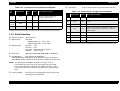
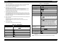
Revision Status
Revision
Date of Issue
A
May 11, 2000
Description
First Release
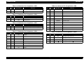
Contents
Chapter 1 Product Description
1.1 Features .............................................................................................. 9
1.2 Printing Specification ...................................................................... 10
1.2.1 Printing Specification ................................................................. 10
1.2.2 Paper Feeding ........................................................................... 13
1.2.3 Electrical Specification .............................................................. 14
1.2.4 Environmental Condition ........................................................... 14
1.2.5 Reliability ................................................................................... 14
1.2.6 Ribbon Cartridge ....................................................................... 14
1.2.7 Safety Approvals ....................................................................... 15
1.2.8 CE Marking ................................................................................ 15
1.2.9 Acoustic noise: .......................................................................... 15
1.2.10 Printable Area .......................................................................... 16
1.3 Interface Specifications .................................................................. 19
1.3.1 Parallel Interface (Forward Channel) ........................................ 19
1.3.2 Parallel Interface (Reverse Channel) ........................................ 21
1.3.3 Serial Interface .......................................................................... 22
1.3.4 Interface Selection ..................................................................... 23
1.3.5 Prevention Hosts from Data Transfer Time-out ......................... 23
1.3.6 IEEE1284.4 protocol ................................................................. 23
1.4 Operation .......................................................................................... 24
1.4.1 Control Panel ............................................................................. 24
1.4.1.1 Switches ............................................................................. 24
1.4.1.2 LED .................................................................................... 25
1.4.1.3 Buzzer ................................................................................ 25
1.4.2 Functions ................................................................................... 26
1.4.2.1 Usual Operation ................................................................. 26
1.4.2.2 Operation at Power-on ....................................................... 26
1.4.2.3 Default Setting .................................................................... 26
1.4.2.4 Bi-d. Adjustment ................................................................. 28
1.4.3 Errors ......................................................................................... 28
1.5 Control codes .................................................................................. 29
1.5.1 ESC/P2 ...................................................................................... 29
1.5.2 IBM 2390 Plus Emulation ..........................................................
1.5.3 Bi-Directional Commands .........................................................
1.5.3.1 Reply Printer Status ...........................................................
1.5.3.2 Packet commands ..............................................................
30
31
33
34
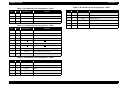
1.6 Initialization ...................................................................................... 35
1.7 Paper Specifications ....................................................................... 36
1.8 Physical Specifications .................................................................. 39
1.9 Accessories ..................................................................................... 40
Chapter 2 Operating Principles
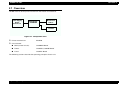
2.1 Overview .......................................................................................... 42
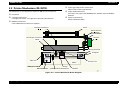
2.2 Printer Mechanism (M-3M10) .......................................................... 43
2.2.1 Printhead ................................................................................... 44
2.2.1.1 Buzzer Function ................................................................. 44
2.2.2 Carriage Mechanism ................................................................. 45
2.2.2.1 High speed skip method ..................................................... 47
2.2.3 Ribbon Mechanism ................................................................... 47
2.2.3.1 Ink Ribbon Shifting Mechanism .......................................... 47
2.2.3.2 Color Ribbon Driving Mechanism (Option) ......................... 47
2.2.4 Platen Gap Adjustment Mechanism .......................................... 49
2.2.5 Paper Feed Mechanism ............................................................ 50
2.2.5.1 Page Length Measurement ................................................ 51
2.2.6 Release Mechanism .................................................................. 52
2.2.7 Other Special Functions ............................................................ 52
2.2.7.1 Energy saving mode ........................................................... 52
2.2.7.2 Quiet Mode ......................................................................... 52
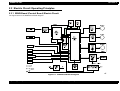
2.3 Electric Circuit Operating Principles .............................................
2.3.1 MAIN Board (Control Board) Electric Circuit .............................
2.3.2 C294PSB / C294PSE Board .....................................................
2.3.2.1 Electric Circuit ....................................................................
53
53
54
54
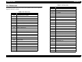
Chapter 3 Troubleshooting
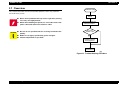
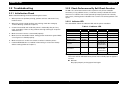
3.1 Overview ........................................................................................... 56
3.2 Troubleshooting .............................................................................. 57
3.2.1 Initialization Check .................................................................... 57
3.2.2 Check Performance By Self-Check Function ............................ 57
3.2.2.1 Indicator LED ...................................................................... 57
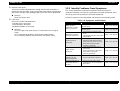
3.2.3 Identify Problems From Symptoms ........................................... 58
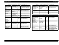
3.2.4 Unit and Parts Check ................................................................ 61
3.2.4.1 Printhead Check ................................................................. 61
3.2.4.2 Motor Check ....................................................................... 62
3.2.4.3 Sensor Check ..................................................................... 62
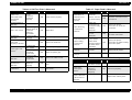
3.2.4.4 Printhead Driver Check ...................................................... 63
Chapter 4 Disassembly and Assembly
4.1 Overview ........................................................................................... 65
4.1.1 Precautions ............................................................................... 65
4.1.2 Tools .......................................................................................... 65
4.1.3 Service Checks After Repair ..................................................... 66
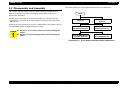
4.2 Disassembly and Assembly ........................................................... 67
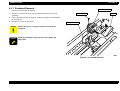
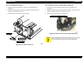
4.2.1 Printhead Removal .................................................................... 68
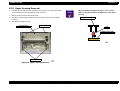
4.2.2 Upper Housing Removal ........................................................... 69
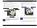
4.2.3 Printer Mechanism Removal ..................................................... 70
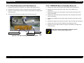
4.2.4 Board Assembly and Panel Removal ........................................ 71
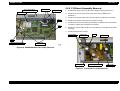
4.2.5 C294MAIN Board Assembly Removal ...................................... 71
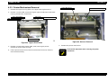
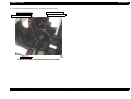
4.2.6 P/S Board Assembly Removal .................................................. 72
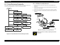
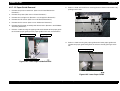
4.2.7 Printer Mechanism Disassembly ............................................... 73
4.2.7.1 CR Motor Assembly Removal ............................................ 73
4.2.7.2 Platen Removal .................................................................. 74
4.2.7.3 Carriage Unit Removal ....................................................... 75
4.2.7.4 Ribbon Feed Mechanism Removal .................................... 76
4.2.7.5 RPE Sensor Removal ........................................................ 77
4.2.7.6 BPE Sensor Removal ......................................................... 77
4.2.7.7 HP Sensor Removal ........................................................... 77
4.2.7.8 PG Sensor Removal ........................................................... 78
4.2.7.9 Release Lever Position Sensor Removal ........................... 78
4.2.7.10 PF Motor Assembly Removal ........................................... 79
4.2.7.11 Paper Feed Mechanism Disassembly .............................. 79
4.2.7.12 Paper Guide Removal ...................................................... 81
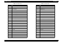
Chapter 5 Adjustment
5.1 Overview .......................................................................................... 83
5.1.1 Platen Gap Adjustment ............................................................. 83
5.1.2 Bi-D Adjustment ........................................................................ 84
Chapter 6 Maintenance
6.1 Maintenance ..................................................................................... 89
6.1.1 Cleaning .................................................................................... 89
6.1.2 Lubrication ................................................................................. 89
Chapter 7 Appendix
7.1 Connector Summary ....................................................................... 94
7.2 Parts List .......................................................................................... 97
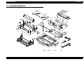
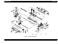
7.3 Exploded Diagrams ....................................................................... 100
7.4 Component Layout ....................................................................... 102
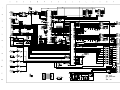
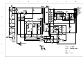
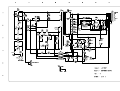
7.5 Circuit Schematics ........................................................................ 103
CHAPTER
1
PRODUCT DESCRIPTION
LX-300+
Revision A
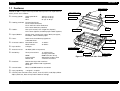
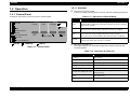
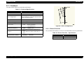
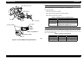
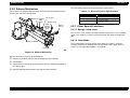
1.1 Features
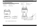
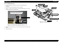
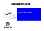
Paper supports
EPSON LX-300+ is a 9-pin serial impact dot matrix printer. The major features
of this printer are as follows:
Printing speed:
High speed draft
Draft
NLQ
Paper guide cover
Paper guide
300 cps at 10 cpi
225 cps at 10 cpi
56 cps at 10 cpi
Printer cover
Paper release lever
Feeding method: Friction feed (rear)
Push tractor feed (rear)
Push and Pull tractor feed (rear)
Pull tractor feed (rear, bottom)
Knob
Feeder:
Rear push tractor, CSF single-bin (Option),
Pull tractor (Option) and Roll paper holder (Option)
Paper/ Media:
Single sheet, Continuous paper, Multi part paper,
Envelope, Label and Roll paper
Fonts:
2NLQ and 1 Draft Bitmap typefaces
8 Barcode fonts
Character tables: Standard version
NLSP version
Control panel
Ribbon cartridge
Paper thickness
lever
13 tables
38 tables
Input buffer:
8 Kbytes
Acoustic noise:
49 dB(A) (ISO 7779 pattern)
Reliability:
Total print volume
Paper tension unit
Parallel interface
Tractor
MTBF
Printhead life
Ribbon life
12 million lines
(except printhead)
6000 POH (25% Duty)
200 million strokes/ wire
3 million characters
Interface:
Bi-directional parallel interface
(IEEE-1284 nibble mode supported)
Serial I/F
Control code:
ESC/P and IBM 2380 Plus emulation
Copy capability:
1 original + 4 copies
Paper cord
Power switch
Figure 1-1. EPSON LX-300+ Printer Parts
Control panel functions:Font, Pause, Tear off, LF/FF, Load/ Eject, Micro
Adjust, Self test, Data dump and the default settings
Product Description
Features
9
LX-300+
Revision A
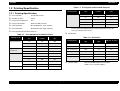
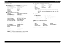
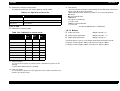
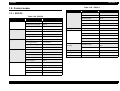
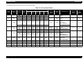
1.2 Printing Specification
Table 1-1. Print Speed and Printable Columns
Printing mode
1.2.1 Printing Specification
NLQ
Print method:
Impact dot matrix
Number of pins:
9 pins
Print pin arrangement:
9x1
Print pin diameter:
0.29 mm (0.0114 inch)
Color (Option):
Black, Magenta, Cyan, Yellow
Print direction:
Bi-direction with logic seeking
Character pitch
(cpi)
Printable
columns
Printing speed
(cps)
10
80
300
Printing mode
12
96
337
15
120
17
High speed draft
condensed
Draft
Draft condensed
Draft emphasized
Product Description
Printing speed
(cps)
10
80
56
12
96
67
15
120
56
17
137
47
20
160
56
Resolution:
Table 1-1. Print Speed and Printable Columns
High speed draft
Printable
columns
NOTE: When the power supply voltage drops to the lower limit, the
printer stops printing and then starts printing the rest on the
line more slowly than before.
Print speed and printable columns:
Printing mode
Character pitch
(cpi)
Table 1-2. Resolution
Horizontal density
(dpi)
Vertical density
(dpi)
Adjacent dot print
High speed draft
90
72
No
337
Draft
120
72
No
137
321
Draft condensed
240
72
No
20
160
300
Draft emphasized
120
72
Yes
10
8-
225
NLQ
240
144
No
12
96
270
Bit image
60, 72, 80, 90 or 120
72
Yes
15
120
225
120 or 240
72
No
17
137
191
20
160
225
10
80
112
Control code:
Printing Specification
ESC/P and IBM 2380 Plus emulation
(Refer to 1.5 "Control codes")
10
LX-300+
Revision A
International character sets: 13 countries
Character tables:
Standard version (13 character table)
Italic table
PC850 (Multilingual)
PC863 (Canadian-French)
PC861 (Icelandic)
Abicomp
ISO Latin 1
ISO 8859-15
PC437 (US, Standard Europe)
PC860 (Portuguese)
PC865 (Nordic)
BRASCII
Roman 8
PC858
NLSP version (38 character tables)
Italic table
PC850 (Multilingual)
PC853 (Turkish)
PC852 (East Europe)
PC866 (Russian)
PC869 (Greek)
Code MJK (CSFR)
ISO Latin 1T (Turkish)
PC 774 (LST 1283:1993)
ISO 8859-2
PC 866 UKR (Ukrania)
PC 861 (Icelandic)
PC APTEC (Arabic)
PC 720 (Arabic)
PC863 (Canadian-French)
BRASCII
ISO Latin 1
Hebrew 8*1
PC858
PC771 (Lithuania)
PC437 (US, Standard Europe)
PC437 Greek
PC855 (Cyrillic)
PC857 (Turkish)
MAZOWIA (Poland)
ISO 8859-7 (Latin / Greek)
Bulgaria (Bulgarian)
Estonia (Estonia)
PC 866 LAT. (Latvian)
PC860 (Portuguese)
PC865 (Nordic)
PC708 (Arabic)
PCAR864 (Arabic)
Abicomp
Roman 8
Hebrew 7*1
PC862 (Hebrew)*1
IAO8859-15
U.S.A
U.K.
Italy
Norway
Latin America
France
Denmark 1
Spain 1
Denmark 2
Germany
Sweden
Japan
Spain 2
NOTE: The international and legal characters are the following
12 codes;
23H, 24H, 40H, 5BH, 5CH, 5DH, 5EH, 60H, 7BH, 7CH, 7DH,
7EH.
Typeface
Bit map fonts:
EPSON Draft
EPSON Roman
EPSON Sans serif
EPSON OCR-B
10cpi, 12cpi, 15cpi
10cpi, 12cpi, 15cpi, Proportional
10cpi, 12cpi, 15cpi, Proportional
10cpi*1
NOTE: *1: Do not describe in manual.
Bar codes
EAN-13
UPC-A
Code 128
Industrial 2 of 5 *1
EAN-8
UPC-E
POSTNET
Matrix 2 of 5 *1
Interleaved 2 of 5
Code 39
Coda bar (NW-7)*1
NOTE: *1: Do not describe in manual.
NOTE: *1: This item is not displayed on a default setting
mode. Do not describe this in the manual.
Product Description
Printing Specification
11
LX-300+
Revision A
Character tables and typefaces:
Table 1-3. Character Tables and Typefaces
Character table
Table 1-3. Character Tables and Typefaces
Character table
Standard
version
Italic table
PC 437 (US, Standard Europe)
PC 850 (Multilingual)
PC 860 (Portuguese)
PC 863(CanadianFrench)
PC 865 (Nordic)
PC 861 (Icelandic)
BRASCII
Abicomp
Roman 8
ISO Latin 1
PC 858
ISO 8859-15
Bitmap font
NLSP
version
EPSON Draft
EPSON Roman
EPSON Sans serif
EPSON OCR-B
EPSON Draft
EPSON Roman
EPSON Sans serif
Bitmap font
Italic table
PC 437(US, Standard Europe)
EPSON Draft
EPSON Roman
EPSON Sans serif
EPSON OCR-B
PC 860(Portuguese)
PC 865(Nordic)
BRASCIl
Roman 8
PC437 (Greek)
PC 855 (Cyrillic)
PC 857 (Turkish)
PC 869 (Greek)
Code MJK (CSFR)
lSO Latin 1T (Turkish)
PC774 (LST 1283: 1993)
1SO 8859-2
PC 866 UKR (Ukrania)
PC 708 (Arabic)
PCAR864 (Arabic)
Hebrew 8*1
PC 858
PC771 (Lithuania)
EPSON Draft
EPSON Roman
EPSON Sans serif
PC 850 (Multilingual)
PC 861 (Icelandic)
PC863 (CanadianFrench)
Abicomp
lSOLatin1
PC 853 (Turkish)
PC 852 (East Europe)
PC 866 (Russian)
MAZOWIA (Poland)
lSO 8859-7 (Latin/
Greek)
Bulgaria (Bulgarian)
Estonia (Estonia)
PC 866 LAT. (Latvian)
PC APTEC (Arabic)
PC 720 (Arabic)
Hebrew7*1
PC862 (Hebrew)*1
ISO 8859-15
NOTE: ESC R command is effective on all the character tables.
NOTE: *1: These items are not displayed in the default setting
mode. Do not describe in the manual.
Product Description
Printing Specification
12
LX-300+
Revision A
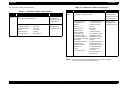
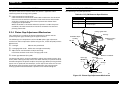
1.2.2 Paper Feeding
Table 1-4. Release Lever
Feeding method: Friction feed (rear)
Lever position
Push tractor feed (rear)
Push and Pull tractor feed (rear)
Pull tractor feed (rear, bottom)
Tractor
Feeder:
Rear push tractor, CSF single-bin (Option),
Pull tractor (Option) and Roll paper holder (Option)
Paper path:
Manual insertion
CSF
Push Tractor
Pull Tractor
Line spacing:
Rear in, top out
Rear in, top out
Rear in, top out
Rear or bottom in, top out
4.23mm (1/6 inch) or programmable
in increments of 0.118mm (1/216 inch)
Feed speed:
4.23mm (1/6 inch feed)
Continuous feed
88msec
0.76MPS (m/sec)
[3.0 IPS (inches/sec)]
Release lever:
The release lever must be set according to the following table;
Table 1-4. Release Lever
Friction
Paper path/ Feeder
Manual insertion (rear)
Paper/ Media
Cut sheet (Single sheet and
Multi part)
Envelop
CSF single-bin
Cut sheet (Single sheet)
Roll paper holder feed (rear)
Roll paper
Product Description
Paper/ Media
Push tractor feed (rear)
Continuous paper (Single
sheet and Multi part)
Push and Pull tractor feed
(rear)
Continuous paper (Single
sheet and Multi part)
Pull tractor feed (rear)
Continuous paper (Single
sheet and Multi part)
Pull tractor feed (bottom)
Continuous paper (Single
sheet and Multi part)
Labels
Paper thickness lever:
The paper thickness lever must be set at the proper position as shown
below.
Table 1-5. Paper Thickness Lever
Input Data Buffer: 8 Kbyte
Lever position
Paper path/ Feeder
Paper thickness (inch)
Lever
position
Minimum
Maximum
0
(0.0024)
(0.0071)
over 0.06 up to 0.18
1
(0.0071)
(0.0102)
over 0.18 up to 0.26
2
(0.0102)
(0.0130)
over 0.26 up to 0.33
3
(0.0130)
(0.0154)
over 0.33 up to 0.39
4
(0.0154)
(0.0205)
over 0.39 up to 0.52
Printing Specification
Paper thickness (mm)
13
LX-300+
Revision A
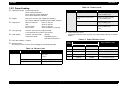
1.2.3 Electrical Specification
1.2.4 Environmental Condition
120 V version
Temperature:
5 to 35 °C (operating*1)
15 to 25 °C (operating*1,*2)
-30 to 60 °C (non-operating)
Humidity:
10 to 80% RH (operating*1)
30 to 60% RH (operating*1,*2)
0 to 85% RH (non-operating)
Resistance to shock:
1 G, within 1ms (operating)
2 G, within 2ms (non-operating*3)
Resistance to vibration:
0.25 G, 10 to 55 Hz (operating)
0.50 G, 10 to 55 Hz (non-operating*3)
Rated voltage:
AC 120V
Input voltage range:
AC 99 to 132 V
Rated frequency range: 50 to 60 Hz
Input frequency range: 49.5 to 60.5 Hz
Rated current:
0.6A (max. 1.4A)
Power consumption:
approx. 23W (ISO/IEC 10561 Letter pattern)
Insulation resistance:
10MΩ min.
(between AC line and chassis, DC 500V)
Dielectric strength:
AC 1000 Vrms. 1 min. or
AC 1200 Vrms. 1 sec.
(between AC line and chassis)
230 V version
*1: without condensation
*2: during printing on multi part paper, envelop, card, or label
*3: without shipment container
1.2.5 Reliability
Rated voltage range:
AC 220 to 240 V
Total print volume:12 million lines (except printhead)
Input voltage range:
AC 198 to 264 V
MTBF:
6000 POH
Printhead life:
400 million strokes / wire (Black)
100 million strokes / wire (Color)
Rated frequency range: 50 to 60 Hz
Input frequency range: 49.5 to 60.5 Hz
Rated current:
0.3 A (max. 0.7A)
Power consumption:
1.2.6 Ribbon Cartridge
approx. 23W (ISO/IEC10561 Letter pattern)
Insulation resistance:
Type:
10MΩ min.
(between AC line and chassis, DC 500V)
Dielectric strength:
AC 1500 Vrms. 1 min.
(between AC line and chassis)
Color:
Ribbon life:
Type:
Color:
Ribbon life:
Product Description
Fabric
Black
3 million characters
(Draft 10 cpi, 14 dots/character)
Fabric
Black, Magenta, Cyan and Yellow
Black
1 million characters (Draft 10 cpi, 14 dots/character)
Magenta
0.7 million characters (Draft 10 cpi, 14 dots/character)
Cyan
0.7 million characters (Draft 10 cpi, 14 dots/character)
Printing Specification
14
LX-300+
Yellow
Revision A
0.5 million characters (Draft 10 cpi, 14 dots/character)
1.2.7 Safety Approvals
120 V version
Safety standards:
UL1950
CSA C22.2 No. 950
EMI:
FCC part15 subpart B class B
CSA C108.8 class B
230 V version
Safety standards:
EN60950 (VDE)
EMI:
EN55022 (CISPR pub.22) class B
AS/NZS 3548 class B
1.2.8 CE Marking
230 V version and UPS version
Low voltage directive 73/23/EEC:
EN60950
EMC Directive 89/336/EEC:
EN55022 class B
EN61000-3-2
EN61000-3-3
EN50082-1
IEC801-2
IEC801-3
IEC801-4
1.2.9 Acoustic noise:
Level:
Product Description
49 dB(A) (ISO 7779 pattern)
Printing Specification
15
LX-300+
Revision A
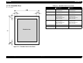
1.2.10 Printable Area
Table 1-6. Printable Area for Cut Sheet
Cut sheets
P r in ta b le A r e a
Single Sheet
Multi Part
PW (Width)
Refer to 1.7 "Paper
Specifications"
Refer to 1.7 "Paper
Specifications"
PL (Length)
Refer to 1.7 "Paper
Specifications"
Refer to 1.7 "Paper
Specifications"
LM (Left Margin)
When PW<=229 mm:
3 mm or more
When PW=257 mm:
24mm or more
When PW<=229 mm:
3 mm or more
When PW=257 mm:
24mm or more
RM (Right Margin)
When PW<=229 mm:
3 mm or more
When PW=257 mm:
24mm or more
When PW<=229 mm:
3 mm or more
When PW=257 mm:
24mm or more
TM (Top Margin)
4.2 mm or more
4.2 mm or more
BM (Bottom Margin) 4.2 mm or more
4.2 mm or more
NOTE: The maximum horizontal printable area is 203.2mm.
Figure 1-2. Printable Area for Cut Sheet
Product Description
Printing Specification
16
LX-300+
Revision A
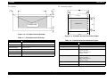
Continuous paper
Envelop
R M
L M
T M
P e r fo r a tio n
P r in ta b le A r e a
P r in ta b le A r e a
B M
P e r fo r a tio n
Figure 1-3. Printable Area for Envelop
Figure 1-4. Printable Area for Continuous Paper
Table 1-7. Printable Area for Envelop
Table 1-8. Printable Area for Continuous Paper
Envelope Printable Area
Continuous Paper
PW (Width)
Refer to 1.7 "Paper Specifications"
PL (Length)
Refer to 1.7 "Paper Specifications"
PW (Width)
Refer to 1.7 "Paper Specifications"
LM (Left Margin)
3 mm or more
PL (Length)
Refer to 1.7 "Paper Specifications"
RM (Right Margin)
3 mm or more
LM (Left Margin)
TM (Top Margin)
4.2 mm or more
BM (Bottom Margin)
4.2 mm or more
When PW<=254mm:
13 mm or more
When PW=254 mm:
24mm or more
RM (Right Margin)
When PW<=254mm:
13 mm or more
When PW=254 mm:
24mm or more
TM (Top Margin)
4.2 mm or more
BM (Bottom Margin)
4.2 mm or more
NOTE: The maximum horizontal printable area is 203.2mm.
NOTE: The maximum horizontal printable area is 203.2mm.
Product Description
Printing Specification
17
LX-300+
Revision A
Roll paper
P W
L M
B M
T M
P r in ta b le A r e a
B M
Figure 1-5. Printable Area for Roll Paper
Table 1-9. Printable Area for Roll Paper
Continuous Paper
PW (Width)
Refer to 1.7 "Paper Specifications"
PL (Length)
Refer to 1.7 "Paper Specifications"
LM (Left Margin)
3 mm or more
RM (Right Margin)
3 mm or more
TM (Top Margin)
4.2 mm or more
BM (Bottom Margin)
4.2 mm or more
Product Description
Printing Specification
18
LX-300+
Revision A
1.3 Interface Specifications
LX-300+ provides bi-directional 8 bit parallel interface and serial interface.
Optional interface board is not supported on this model.
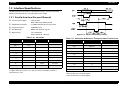
1.3.1 Parallel Interface (Forward Channel)
Transmission mode:
8 bit parallel
IEEE-1284 compatibility mode
Adaptable connector:
57-30360 (Amphenol) or equivalent
Synchronization:
-STROBE pulse
Handshaking:
BUSY and -ACKLG signals
Signal level:
TTL compatible
(IEEE-1284 level 1 device)
Figure 1-6. Data Transmitting Timing
Table 1-10. Parameter
Table 1-11. Maximum & Minimum Timings for Data Transmission
Parameter
Minimum
Maximum
Condition
VOH*
--
5.5V
VOL*
-0.5V
--
IOH*
--
0.32mA
VOH=2.4V
IOL*
--
12mA
VOL=2.4V
CO
--
50pF
VIH
--
2.0V
VIL
0.8V
--
IIH
--
0.32mA
VIH=2.0V
IIL
--
12mA
VIL=0.8V
CI
--
50pF
* Logic-H signal is 2.0V or lower when the printer is off and the signal is 3.0V
or higher when the printer is on. The receiver has impedance which is
equivalent to 7.5 kΩ.
Product Description
Parameter
Minimum
Maximum
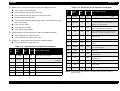
tsetup
500 nsec
--
thold
500 nsec
--
tstb
500 nsec
--
tready
0
--
tbusy
--
500 nsec
treply
--
--
tack
500 nsec
10 us
tnbusy
0
--
tnext
0
--
ttout*
--
120 nsec
ttin**
--
200 nsec
* Rise and fall time of output signals
** Rise and fall time of input signals.
Interface Specifications
19
LX-300+
Revision A
BUSY signal is active (HIGH level) under the conditions below:
In the process of receiving data
Table 1-12. Connector Pin Assignment and Signals
Pin
No.
In the condition of being input buffer full
Signal
Name
Return
GND
Pin
In/Out
Functional Description
In the condition of being -INT signal active (low level)
8
DATA7
26
In
bit6
During hardware initialization
9
DATA8
27
In
bit7:MSB
10
-ACKNLG
28
Out
This signal (negative pulse) indicates
that the printer has received data and is
ready to accept next one.
11
BUSY
29
Out
This signal’s high level means that the
print is not ready to accept data.
12
PE
28
Out
This signal’s high level means that the
printer is in a state of paper-out error.
13
SLCT
28
Out
Always at high level when the printer is
powered on.
14
-AFXT
30
In
Not used.
31
-INIT
30
In
This signal’s negative pulse initializes
printer.
32
-ERROR
29
Out
36
-SLIN
30
In
18
Logic H
--
Out
This line is pulled up to +5V through
3.9 kΩ resister.
35
+5V
--
Out
This line is pulled up tp +5V through
1.0 kΩ resister.
17
Chassis
--
--
Chassis GND.
In the condition of being -ERROR or PE signal is active (low level, high
level, respectively)
In the self test mode
In the adjustment mode
In the default-setting mode
-ERROR signal is active (low level) under the conditions below:
In the condition of a paper-out error
In the condition of a release lever error
PE signal is active (high level) under the condition below:
In the condition of a paper-out error
Table 1-12. Connector Pin Assignment and Signals
Pin
No.
1
Signal
Name
-STROBE
Return
GND
Pin
19
In/Out
Functional Description
In
Strobe pulse. Input data is latched at
falling edge of the signal.
Parallel input data to the printer.
bit0:LSB
This signal’s low level means the printer
is in a state of error.
Not used.
2
DATA1
20
In
3
DATA2
21
In
bit1
4
DATA3
22
In
bit2
16, 33,
19-30
GND
--
--
Signal GND.
5
DATA4
23
In
bit3
15, 34
NC
--
--
Not connected.
6
DATA5
24
In
bit4
7
DATA6
25
In
bit5
Product Description
NOTE: In/Out shows the direction of signal flow from the printer’s
point of view.
Interface Specifications
20
LX-300+
Revision A
1.3.2 Parallel Interface (Reverse Channel)
Transmission mode:
Adaptable connector:
Table 1-15. Connector Pin Assignment and Signals
IEEE-1284 nibble mode
See 1.3.1 "Parallel Interface (Forward
Pin
No.
Signal Name
Channel)"
Return
GND
Pin
In/Out
Functional Description
1
HostClk
19
In
Host clock signal.
2
DATA1
20
In
Parallel input data to the printer.
bit0:LSB
3
DATA2
21
In
bit1
Data transmission timing: Refer to the IEEE-1284 specification
4
DATA3
22
In
bit2
Extensibility request:
5
DATA4
23
In
bit3
6
DATA5
24
In
bit4
7
DATA6
25
In
bit5
8
DATA7
26
In
bit6
9
DATA8
27
In
10
PtrClk
28
Out
Printer clock signal.
11
PtrBusy/
DataBit-3,7
29
Out
Printer busy signal and reverse
channel transfer data bit 3 or 7.
12
AckDataReq/
DataBit-2,6
28
Out
Acknowledge data request signal
and reverse channel transfer data
bit 2 or 6.
13
Xflag/
DataBit-1,5
28
Out
X-flag signal and reverse channel
transfer data bit 1 or 5.
14
HostBusy
30
In
Host busy signal.
31
-INIT
30
In
Not used.
32
-DataAvail/
DataBit-0,4
29
Out
36
1284-Active
30
In
18
Logic-H
--
Out
Synchronization:
Refer to the IEEE-1284 specification
Handshaking:
Refer to the IEEE-1284 specification
Signal level:
IEEE-1284 level 1 device
See 1.3.1 "Parallel Interface (Forward Channel)"
The printer responds to the extensibility
request affirmatively, when the request is 00H or 004H, which means;
00H: Request for nibble mode of reverse channel transfer
04H: Request device ID in nibble mode of reverse channel transfer
Device ID: The printer sends following device ID string when it is
requested.
When IEEE1284.4 is enabled;
Table 1-13.
[00H][4EH]
MFG: EPSON;
CMD: ESCPL2,PRPXL24,BDC,D4;
MDL: LX-300+;
CLS: PRINTER;
DES: EPSON[SP]LX-300+;
When IEEE1284.4 is disabled;
Table 1-14.
[00H][4BH]
MFG: EPSON;
CMD: ESCPL2,PRPXL24,BDC;
MDL: LX-300+;
CLS: PRINTER;
DES: EPSON[SP]LX-300+;
Product Description
Interface Specifications
bit7:MSB
Data available signal and reverse
channel transfer data bit 0 or 4.
1284 active signal.
This line is pulled up to +5V
through 3.9 kΩ resister.
21
LX-300+
Revision A
Table 1-15. Connector Pin Assignment and Signals
Pin
No.
Signal Name
Return
GND
Pin
In/Out
35
+5V
--
Out
17
Chassis
--
--
16, 33,
19-30
GND
--
--
15, 34
NC
--
--
Connector:
25 pin subminiature D-shell connector (female)
Table 1-16. Connector Pin Assignment and Signals
Functional Description
This line is pulled up tp +5V
through 1.0 kΩ resister.
Chassis GND.
Pin
No.
Signal Name
In/Out
2
TXD
Out
Transmit data.
20
DTR
Out
Indicates that the printer is ready to receive data
or not.
11
REV
Out
Connected directly to the DTR signal.
4
RTS
Out
Request to send. Always SPACE level when the
printer is powered on. Pulled up to +12V via
4.7KΩ resistor.
Signal GND.
Not connected.
* In/Out shows the direction of signal flow from the printer’s point of view.
Functional Description
3
RXD
In
Receive data.
1.3.3 Serial Interface
7
Signal GND
--
Signal GND
Synchronization: Asynchronous
1
Chassis GND
--
Chassis GND
other
NC
--
Not used. Not connected.
Signal level:
EIA-232D
MARK (logical 1): -3V to -25V
SPACE (logical 0): +3V to +25V
* In/Out shows the direction of signal flow from the printer’s point of view.
Word length:
Start bit:
Data bit:
Parity bit:
Stop bit:
Baud rate:
300, 600, 1200, 2400, 4800, 9600 or 19200 bps
1 bit
8 bit
Odd, Even, Non, Ignore
1 bit or more
Handshaking:
DTR signal and XON/XOFF
DTR=MAEK, XOFF:indicates that the printer cannot receive data.
DTR=MARK, XON: indicates that the printer is ready to receive data.
NOTE: The DTR signal is MARK and XOFF code (DC3, 13H) is
transmitted when the rest of the input buffer becomes 256
bytes. The DTR signal is SPACE and XON code (DC1, 11H) is
transmitted when the rest of the input buffer is regained 256
byte.
Error handling:
Product Description
Parity error is only detected. Overrun error and
framing error are ignored.
Interface Specifications
22
LX-300+
Revision A
Auto:
1.3.4 Interface Selection
The printer has 2 interfaces; the parallel interface and serial interface. These
interfaces are selected manually by Default Setting or selected automatically.
Manual Selection
Communication is carried out in the conventional mode until a magic
string (1284.4 synchronous commands) is received. By receiving a
magic string, communication in IEEE1284.4 packet mode is started.
Off:
One of 2 interfaces can be selected by Default setting.
Communication is carried out in the conventional mode. A magic
string (284.4 synchronous commands) is discarded.
Automatic Selection
The automatic interface selection is enabled by Default Setting. In this
automatic interface selection mode, the printer is initialized to the idle
state scanning which interface receives data when it is powered on.
Then the interface that receives data first is selected. When the host
stops data transfer and the printer is in stand-by state for the seconds
specified by Default Setting, the printer is returned to the idle state. As
long as the host sends data or the printer interface is in busy state, the
selected interface is let as it is.
Interface State and Interface Selection
When the parallel interface is not selected, the interface gets into a
busy state. When the serial interface is not selected, the interface
sends XOFF and sets the DTR signal MARK. When the printer is
initialized or returned to the idle state, the parallel interface got into a
ready state, the serial interface sends XON and sets the DTR SPACE.
Caution that the interrupt signal such as a -INIT signal on the parallel
interface is not effective while that interface is not selected.
NOTE: The packet protocol of IEEE1284.4 allows a device to carry on
multiple exchanges or conversations which contain data and/
or control information with another device at the same time
across a single point-to-point link.
The protocol is not, however, a device control language. It
does provide basic transport-level flow control and
multiplexing services.
The multiplexed logical channels are independent of each and
blocking of one has no effect on the others. The protocol
operates over IEEE1284.
1.3.5 Prevention Hosts from Data Transfer Time-out
Generally, hosts abandons data transfer to peripherals when a peripheral is in
busy state for dozens of seconds continuously. To prevent hosts from this
kind of time-out, the printer receives data very slowly, several bytes per
minute, even if the printer is in busy state. This slowdown is started when the
rest of the input buffer becomes several hundreds of bytes. At last, when the
input buffer is full, the printer is in busy state continuously.
1.3.6 IEEE1284.4 protocol
The packet protocol described by IEEE1284.4 is supported on the parallel I/F.
Two function modes of IEEE1284.4 protocol, “Off” and “Auto” are available,
and one of them is selected according to the value of Default setting. (See
1.4.2.3 "Default Setting")
Product Description
Interface Specifications
23
LX-300+
Revision A
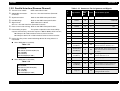
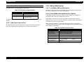
1.4 Operation
1.4.1.1 Switches
Operation in normal mode
In normal mode, pressing panel switches executes following function;
1.4.1 Control Panel
Table 1-17. Operation in Normal Mode
4 switches and 4 LEDs are on the panel as shown below.
Tear Off
Tear Off
LF/FF
Load/Eject
Paper Out
Switch
Function
Pause
-Alternates printing and non-printing status.
-Enables Micro Adjustment function and Font selection, holding it
down for 3 seconds.
Load/Eject
-Loads or ejects paper.
-Execute micro feed forward, when this function is enabled.
LF/FF
-Executes line feed, pressing it shortly.
-Executes form feed, holding it down for a few seconds.
-Executes micro feed backward, when this function is enabled.
Tear Off
-Advances continuous paper to the Tear-off position.
-Select font, when this function is enabled.
Pause
Draft
Draft Condensed
Roman
Roman Condensed
Font
Micro Adjust
3 sec
Sans serif
Sans serif Condensed
: LED On
: LED Blinks
: LED Off
Operation at power on
Turning the printer on while pressing panel switches executes the
functions below;
Figure 1-7. Control Panel
Table 1-18. Operation at Power On
Product Description
Switch
Function
Load/Eject
NLQ self test
LF/FF
Draft self test
Tear Off
Default setting
Load/Eject & LF/FF
Data dump
Load/Eject & LF/FF & Pause
Clear EEPROM
Tear Off & Load/Eject & LF/FF
Clear EEPROM for Diving Line count for ribbon
change timing.
Pause
Bi-d adjustment
The others
Not available
Operation
24
LX-300+
Revision A
Operation in default setting mode
*3 Font (Green)
-The status of Font selection is displayed by 2 Font LEDs when continuous
paper is out of the Tear-off position.
-Both LEDs blink when continuous paper is in the Tear-off position.
: Draft
: Draft Condensed
: Roman
: Roman Condensed
: Sans serif
: Sans serif Condensed
: Tear Off
(
: LED On, : LED Off, : LED Blinks)
The following switches are used in default setting mode;
Table 1-19. Operation at Power On
Switch
Function
Tear Off
Changes the setting.
LF/FF
Selects the Menu.
The others
Not available.
1.4.1.2 LED
Indication in normal mode
1.4.1.3 Buzzer
Table 1-20. Indication in normal mode
LED
Pause*1
Printer Status
Paper
Out*2
Font
Pause
On
---
---
Paper out error
On
On
---
Release lever error
On
---
---
Paper eject warning
On
Blink
---
Blink
---
---
Tear off
---
---
*3
Font selection
---
---
*3
Blink
Blink
Blink
Micro Adjust
Fatal error
Paper out error:
Beeper sounds (...)*
Release lever operation:
Beeper sounds(-----)*
Illegal panel operation:
Beeper sounds (.)*
*The description (.) and (-) in the above shows how the beeper sounds.
(.): Beeper sounds approx. 100ms and interval is approx. 100ms.
(-): Beeper sounds approx. 500ms and interval is approx. 100ms.
*1 Pause (Orange)
-It is on when the printer is paused, and it is off when the printer is not
paused.
-It blinks when Micro Adjust is enabled.
*2 Paper Out (Red)
-It is on when the printer is in the Paper out status, and it is off when the
printer is out of this status.
Product Description
Operation
25
LX-300+
Revision A
1.4.2 Functions
1.4.2.2 Operation at Power-on
Self test
1.4.2.1 Usual Operation
Prints the self test pattern. To cancel it, make printer pause and turn
off the power.
Pause
-This switch alternates printer activity between printing and nonprinting.
-By holding it down over 3 seconds when the printer is in the stand by
state, the Micro Adjust function is enabled. By pressing it again, this
function is disabled.
Load/Eject
-Pressing it loads out sheet or continuous paper when the printer is
out of paper.
-Pressing it ejects out sheet to the stacker or continuous paper to the
paper park.
LF/FF
-Pressing it shortly executes line feed.
-Holding it down for a few seconds executes form feed when
continuous paper is used, or ejects cut sheet to the stacker when cut
sheet is used.
Tear Off
-When continuous paper is used, pressing it moves a page to the
Tear-off position. And pressing it again moves a next page to the TOF
position.
Font
-Pressing it selects one of the following fonts when Micro Adjust is
enabled;
Draft, Draft Condensed, Roman, Roman Condensed, Sans serif, Sans
serif Condensed
Micro Adjust
-Micro Adjust ↓ / ↑ switches is effective when the Micro Adjust
function is enabled by Pause switch.
-Pressing the Micro Adjust ↓ / ↑ switches executes micro feed
backward and forward by 0.118 mm (1/216 inch).
-The TOF adjustment is enabled in the TOF position after loading, and
the Tear-off adjustment is enabled in the Tear-off position.
Product Description
Default setting
Starts the default setting mode. See 1.4.2.3 "Default Setting".
Data Dump
Starts the data dump mode, in which all the input data are printed as
hexadecimal numbers and corresponding characters.
Clear EEPROM
Resets the printer to the factory default setting, which is not always
proper setting for each market demand.
(i.e. This function is for emergency.)
Clear Areal EEPROM data except 00H to 1FH.
Clear EEPROM for Driving Line count for ribbon change timing.
Resets the diving Line count for ribbon change timing.
Bi-d adjustment
Starts the Bi-d adjustment mode. See 1.4.2.4 "Bi-d. Adjustment".
Demonstration
Not available.
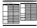
1.4.2.3 Default Setting
There are some parameters that can be changed by users and will be referred
at the time of initialization of the printer.
Setting mode
1.
Enters the Default setting mode.
The method of selecting language for “Usage of this mode” is printed.
2.
Select language for “Usage of this mode” by LF/FF button.
Font LEDs show the language for “Usage of this mode” that is currently
selected.
This section will be advanced one by one as the button is pressed and the
On/Off/Blink/2-Blink of those three LEDs will also be changed according to
the selection.
Operation
26
LX-300+
3.
4.
5.
Revision A
Press Tear Off button.
The current setting and the “Usage of this mode” by selected language
will be printed on the paper set in the paper path at that time.
A print sample is shown in appendix A.
Item
Setting / Value *2
High speed draft
OFF, ON
Select Menu by Tear Off button.
Font LEDs show the menu which is selected at that time. The selection
will be advanced one by one as the button is pressed and the
combination of those three LEDs status of On/Off/Blink/2-Blinks will be
changed according to the selection.
I/F mode
Auto, Parallel, Option
Auto I/F wait time
10 seconds, 30 seconds
Parallel I/F bidirectional
mode
OFF, ON
Select setting value by LF/FF button.
Tear Off/ Bin LEDs and Paper Out LED show that menu’s value by status
of On/Off/Blink/2-Blinks. That value can be changed by pressing Tear Off/
Bin button and the LEDs status of On/Off/Blink/2-Blinks will be changed as
the button is pressed.
Packet mode
Auto, OFF
Auto CR (IBM 2390 Plus)
OFF, ON
A.G.M. (IBM 2390 Plus)
OFF, ON
Character table
Software version
Italic, PC437, PC850, PC860, PC863, PC865, PC861,
BARASCII, Abicomp, Roman8, ISO Latin 1, PC858,
ISO 8859-15
6.
When LF/FF button is pressed, the printer memorize the last setting value.
7.
Repeat (4) to (6).
The other items can be changed in the same manner.
The menu selection will return to the first menu after the last menu
selection is over.
8.
Table 1-21. Setting Menu
NLSP version
Italic, PC437, PC850, PC437, Greek, PC853, PC855,
PC852, PC857, PC864, PC866, PC869, MAZOWIA,
Code MJK, ISO 8859-7, ISO Latin 1T, Bulgaria,
PC774, Estonia, ISO 8859-2, PC 866 LAT., PC
866UKR, PC APTEC, PC708, PC720, PCAR 864,
PC860, PC865, PC861, PC863, BRASCII, Abicomp,
Roman8, ISO Latin 1, PC858, ISO 8859-15, PC771
Turn the printer off.
The setting is stored into non-volatile memory.
Table 1-21. Setting Menu
Item
Setting / Value *2
Page length for tractor
3 inch, 3.5 inch, 4 inch, 5.5 inch, 6 inch, 7 inch,
8 inch, 8.5 inch, 11 inch, 70/6 inch, 12 inch, 14 inch,
17 inch
Italic U.S.A., Italic France, Italic Germany, Italic,
International character set
U.K., Italic Denmark 1, Italic Sweden, Italic Italy,
for Italic table
Italic Spain 1
Manual feed wait time
1 second, 1.5 seconds, 2 seconds, 3 seconds
OFF, ON
Skip over perforation
OFF, ON
Buzzer
Auto tear off
OFF, ON
Auto CR (IBM 2380 Plus)*1
Auto line feed
OFF, ON
IBM character table
Print direction
Bi-d., Uni-d., Auto
Software
ESC/P2, IBM 2390 Plus
NOTE: *1: This setting is effective when IBM 2380 Plus emulation is
selected.
0 slash
OFF, ON
Product Description
*1
OFF, ON
Table2, Table1
NOTE: Setting with underline mean the standard factory settings.
Operation
27
LX-300+
Revision A
1.4.2.4 Bi-d. Adjustment
1.4.3 Errors
Bi-d. adjustment can be adjusted by users. Bi-d. adjustment method is as
follows.
Paper out error:
1.
Release lever error:
When the printer fails to feed a sheet, it goes a paper out error.
Turning the printer on while pressing Pause switch. The guide to adjust
Bi-d alignment in this mode and the first alignment pattern will be
printed.
2.
Select the most closely aligned number by pressing LF/FF (↓) and Load/
Eject (↑) switches.
Font LEDs and Pause LED show the pattern number which is selected at
that time. The selection is advanced one by one as the switch is pressed,
and the combination of On/Off/Blink of those three LEDs is also changed
according to the selection.
3.
Fix the selected number by pressing Tear Off switch.
Selected number is fixed and the next alignment pattern is printed.
4.
Repeat step 2 to 3 until finishing Bi-d adjustment for NLQ mode.
Following adjustment is executed.
- Bi-d. adjustment for high speed draft mode
- Bi-d. adjustment for draft mode
- Bi-d. adjustment for NLQ mode
5.
Turn the printer off.
The setting is stored into non-volatile memory.
Product Description
When release lever position is wrong, it goes a release lever error.
Fatal errors:
Operation
Carriage control error and Power supply voltage error.
28
LX-300+
Revision A
1.5 Control codes
Table 1-22. ESC/P2
1.5.1 ESC/P2
Classification
Operation
Command
Font enhancement
Double-Width
ESC W, DC4, SO
Condensed
DC2, SI
Double-height
ESC w
Double-Strike
ESC G, ESC H
Super-/ Subscript
ESC T, ESC S
Underline
ESC-
Spacing
Intercharacter Space
ESC Space
Character handling
Character Table
ESC t, ESC (t
International Character
ESC R
User-Defined Characters
ESC%, ESC &, ESC:
Control code selection
ESC1
Upper Control Codes
ESC6, ESC7
8 pin Bit Image
ESC K, ESC L, ESC Y, ESC Z,
ESC*
9 pin Bit Image
ESC ^
Table 1-22. ESC/P2
Classification
Operation
Command
General Operation
Initialize Printer
ESC@
Unidirectional Printing
ESC U
CSF Mode Control
ESC EM
Form Feed
FF
Line Feed
LF
Line Spacing
ESC 0, ESC 2, ESC3, ESC A
Carriage Return
CR
Page Length
ESC C, ESC C0, ESC (C
Left / Right Margin
ESC Q, ESC1
Top / Bottom Margin
ESC N, ESC O, ESC (c
Define Unit
ESC (U
Horizontal Print Position
ESC$, ESC¥
Printing color
Select color
ESC r
Vertical Print Position
ESC (V, ESC (v
Bar code
Bar code
ESC (B
Tab Horizontally
ESC D, HT
Production
EEPOM write, etc.
ESC|
Tab Vertically
ESC B, VT
Advance paper
ESC J
Typeface
ESC k, ESC x, ESC y
Pitch
ESC P, ESC M, ESC g, ESC p
Italic Font
ESC 4, ESC 5
Bold Font
ESC E, ESC F
Master Select
ESC!
Paper feeding
Page format
Print position motion
Font selection
Product Description
Bit image
Control codes
29
LX-300+
Revision A
1.5.2 IBM 2390 Plus Emulation
Table 1-23. IBM 2390 Plus emulation
Table 1-23. IBM 2390 Plus emulation
Classification
Operation
Command
General Operation
Nop
NUL, DC3
Off Line
ESC j
Buzzer
BEL
Cancellation
CAN
Select / Deselect
DC1, ESC Q
Initialize Printer
ESC [K
Unidirectional Printing
ESC U
Classification
Operation
Command
Font selection
Pitch
DC 2, ESC P, ESC:
Bold Font
ESC E, ESC F
Master Select
ESC I
Print Quality
ESC [d
Select Font and Pitch
ESC [I
Double-Width
DC4, SO, ESC SO, ESC W
Enlarge and Life Space
ESC [@
Condensed
SI, ESC SI
Double-Strike
ESC G, ESC H
Super-/ Subscript
ESC T, ESC S
Underline
ESC -
Line / Score
ESC_
Back Space
BS
Space
SP
Define Unit
ESC [¥
Character Table
ESC 6, ESC 7, ESC [T
Print Data as Characters
ESC ^, ESC¥
Bit image
Bit Image
ESC K, ESC L, ESC Y, ESC Z
Bar code
Set up Bar code
ESC [f
Transfer Bar code
ESC [p
Download
ESC=(only Draft mode)
Font enhancement
Select Auto Sheet Feeder ESC [F
Paper feeding
Page format
Print position motion
Form Feed
FF
Line Feed,
Auto Line Feed
LF, ESC5
Line Spacing
ESC A, ESC 0, ESC 1, ESC 2,
ESC3
Carriage Return
CR
Reverse Line Feed
ESC]
Page Length
ESC C, ESC C0
Left / Right Margin
ESC X
Skip Over Perforation
ESC N, ESC O
Set TOF
ESC 4
Horizontal Print Position
ESC d
Initialize Tab Position
ESC R
Tab Horizontally
ESC D, HT
Tab Vertically
ESC B, VT
Advance paper
ESC J
Product Description
Spacing
Character handling
Download
Control codes
30
LX-300+
Revision A
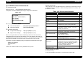
1.5.3 Bi-Directional Commands
<Remote commands>
-[Save] column shows that SV commands is effective to each feature or not.
-{: All parameters are saved., ∆: Some limited parameters are saved.,-: No
parameter is saved.
Reply printer ID
Reply printer ID:
[ESC][SOH]@EJL[SP]ID[CR][LF]
The printer sends the following ID string in reply to this command.
Table 1-25. Bi-Directional Commands
Table 1-24.
Function
Code/ Parameter
Enter Remote-1
ESC”(R”08H 00H 00H “REMOTE1”
-
Exit Remote-1
ESC 00H 00H 00H
-
Save settings
“SV” 00H 00H
-
Initialize
“RS” 00H 00H
-
Load power-on default
“LD” 00H 00H
-
Select typeface
“FO” 02H 00H 00H m1
m1=0(Roman), 1(Sans serif), 5(OCR-B)*1
Select character pitch
“CP” 02H 00H 00H m1
m1=0(10cpi), 1(12cpi), 2(15cpi), 3 (17.1cpi),
4(20cpi), 5(Propotional)
{
Select draft or NLQ
“CQ” 02H 00H 00H m1
m1=0(Draft), 1(LQ), 2(High speed draft)
{
Select character table
XX is a string of 2 ASCII characters of defining a feature of the command.
Following [nL][nH] is two byte hexadecimal value that denotes the length of
the [00H] and [ml]...[mx] parameters. Last [m1] ... [mx] parameters are used to
describe the detailed command function and represent printer settings.
“CT” 02H 00H 00H m1
m1=0 (Table0), 1(Table1)
∆*3
Assign character table
“AT” 04H 00H 00H m1 m2 m3
m1=0(Table0), 1(Table1)
m2, m3=(ESC/P2 Character Table No.)*4
∆*3
The printer sends the following string in reply to the commands of this type:
Select an international
character set
“IC” 02H 00H 00H m1
m1=0(U.S.A), 1(France), 2(Germany), 3(U.K.)
4(Denmark1), 5(Sweden), 6(Italy), 7(Spain1),
8(Japan), 9(Norway), 10(Denmark2),
11(Spain2), 12(Latin America)
∆*5
@EJL[SP]ID[CR][LF]
MFG: EPSON;
CMD: ESCPL2,PRPXL24,BDC;
MDL: LX-300+;
CLS: PRINTER;
DES: EPSON[SP]LX-300+;
[FF]
Enter / Exit Remote Mode
Enter Remote Mode:
[ESC](R[08H][00H][00H]REMOTE1
Exit Remote Mode:
[ESC][NUL][00H][00H]
Remote Commands
Change Printer Settings:
XX[nL][nH][00H][ml]...[mx]
Reply Printer Settings:
XX[nL][nH][01H][ml]...[mx]
@BDC[sp]PS[CR][LF]
XX: Reply-Data;
[FF]
Table 1-25 shows the XXs that are provided in this printer.
Turn 1 inch skip
perforation on/off
“SK” 02H 00H 00H m1
m1=0(off), 1(on)
Save
∆*2
{
*1 Don’t describe in manual.
*2 m1=0 to 1 only
*3 Only the following parameters are memorized. (Table 1-26)
Product Description
Control codes
31
LX-300+
Revision A
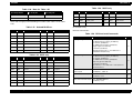
Table 1-28. NLSP only
Table 1-26. Note for Table 1-25
m1 set by AT/CT
m2 set by AT
m3 set by AT
0
0
0
1
All parameters that can be set
*4 m2 and m3 apply to the following ID number. (See Table 1-27 & Table
1-28.)
m2
m3
Character table
m2
m3
Character table
0EH
30H
PC866 UKR
29H
00H
PC 708
0FH
00H
PC869
2AH
00H
PC720
0DH
20H
PCAR_864
7FH
02H
ISO 8859-2
1BH
00H
MAZOWIA
2DH
00H
PC771
*5 m1=0 to 7 only
Table 1-27. Std and NLSP ver.
m2
m3
Character table
m2
m3
Character table
00H
00H
Italic
19H
00H
BRASCII
01H
00H
PC437
1AH
00H
Abicomp
03H
00H
PC850
7FH
01H
ISO Latin1
07H
00H
PC860
23H
00H
Roman8
08H
00H
PC863
2CH
00H
PC858
09H
00H
PC865
1DH
0FH
ISO 8859-15
18H
00H
PC861
<Remote commands>
Table 1-29. Bi-Directional Commands
Table 1-28. NLSP only
Function
Code/ Parameter
Set page length
“PG” 05H 00H 00H p1 p2 m1 m2
p1=0(Continuous paper), p2=0(Rear),
p1=1(CSF), p2=0(bin1)
p1=2(Manual insertion), p2=0(rear)
-Page legth=m1+256*m2,
0.118mm (1/216inch)
648 (76.2mm(3inch)) <= m1+256*m2 <=
4752(558.8mm(22 inch))
{
“TP” 05H 00H 00H p1 p1 m1 m2
p1=0(Continuous paper), p2=0(Rear),
p1=1(CSF), p2=0(bin1)
p1=2(Manual insertion), p2=0(rear)
-Top margin=m1+256*m2,
0.118mm (1/216inch)
36 (4.2mm) <= m1+256*m2 <= 288 (8.5mm +
25.4mm(1inch))
{
“PD” 02H 00H 00H m1
m1=0(Bi-d.), 1(Uni-d.)
{
“TO” 02H 00H 00H m1
m1=0(off), 1(on)
{
Turn auto line feed on/off “LF” 02H 00H 00H m1
m1=0(off), 1(on)
{
Set Top margin
m2
m3
Character table
m2
m3
Character table
01H
10H
PC437 Greek
1CH
00H
Code MJK
05H
00H
PC853
1DH
07H
ISO 8859-7
06H
00H
PC855
1FH
00H
ISO Latin 1T
0AH
00H
PC852
20H
00H
Bulgaria
0BH
00H
PC857
21H
00H
Hebrew 7
Turn unidirectional
mode on/off
0CH
00H
PC862
22H
00H
Hebrew 8
Turn auto tear-off on/off
0DH
00H
PC864
24H
00H
PC 774
0EH
00H
PC866
25H
00H
Estonia
0EH
20H
PC866 LAT.
28H
00H
PC APTEC
Product Description
Control codes
Save
32
LX-300+
Revision A
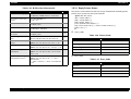
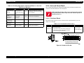
1.5.3.1 Reply Printer Status
Table 1-29. Bi-Directional Commands
Function
Code/ Parameter
Select control language
“PM” 02H 00H 00H m1
m1=0(ESC/P), 2(IBM 238x Plus emulation)
{
Turn printer state reply
on/off
“ST” 02H 00H 00H m1
m1=0, 1, 2, 3
-
Turn Slash zero on/off
“EX” 06H 00H 00H 00H 00H 00H 01H m1
m1=0(off), 1(on)
{
Turn Buzzer on/off
“EX” 06H 00H 00H 00H 00H 00H 02H m1
m1=0(enable), 1(disable)
{
Turn IBM emulation Auto
CR on/off
“EX” 06H 00H 00H 00H 00H 00H 04H m1
m1=0(off), 1(on)
{
Set starting data/month/
year
“SD” 04H 00H 00H m1 m2 m3
00<=m1<=99, 01<=m2<=12, 01<=m3<=31
{
Inquire printer state reply
on/off
“ST” 01H 00H 01H
“@BDC” SP “PS” CR LF “ST:” <nn> “;” FF
-
Echo parameters
“??” nL nH 01H <chr-str>
“@BDC” SP “PS” CR LF “??:” <chr-str> “;” FF
Inquire starting date/
month/year
“SD” 01H 00H 01H
“@BDC” SP “PS” CR LF “SD:” <nn1> <nn2>
<nn3>“;” FF
Inquire total printing
lines/power on hours
“TL” 01H 00H 01H
“@BDC” SP “PS” CR LF “TL:” “;” “TPL:”
<nnnnnnnn2>
“;” “TPH:” <nnnn3>”;” “TPR:” <nnnnnnnn4>
“;” FF
Product Description
Save
-
-
The printer sends back one of the five strings shown below according to the
printer status at that time every few seconds.
“@BDC”SP “ST” CR LF
“ST:” <status code>”;”
[“ER:” <error code>”;”]
[“PP:”<paper_path>”;”]
[”CD:”<printer status codes>”;”]
[“IG:”<nn1><nn2><n3>[“,”...<nnx1><nnx2><nnx3>]”;”]
[“TEC:”<ii1>”;”]
FF
status_code
Table 1-30. Status_Code
Status
“<status code>”
In the error state
“00”
In the busy state
“02”
In the waiting state
“03”
In the idle state
“04”
In the pose state
“05”
error_code
Table 1-31. Error_Code
Error
“<error code>”
Fatal error
“00”
Port is not selected
“01”
Release lever position error
“03”
Paper out
“06”
Control codes
33
LX-300+
Revision A
Paper_path
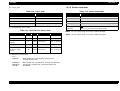
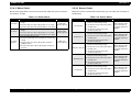
1.5.3.2 Packet commands
Table 1-32. Paper_Path
Table 1-34. Packet Commands
paper_path
“<paper_path code>”
Function
Code
Continuous paper (rear)
“0000”
Device ID request
“di” 01H 00H 01H
Continuous paper (bottom)
“0001”
Device ID reply (*1)
“@EJL” SP “ID” CR LF <Device ID string> FF
Cut sheet (rear)
“0200”
State-Reply request
“st” 01H 00H 01H
CSF Single bin
“0100”
State-Reply (*2)
“@BDC” SP “ST” CR LF <printer status string> FF
No support
command
“XX:;” FF
(XX is the command string being invalid.)
characteristic status code
Table 1-33. Characteristic Status Code
location
size
type
NOTE: (*1) The reply string is as same as BDC-ID Reply.
Refer to
NOTE: (*2) The reply string is as same as BDC-ST Reply.
Structure version
+0
2bytes
“02” fixed
-
Starting date
+2
6bytes
“yy”, “mm, “dd”
“SD” command
Total printing line
number
+8
8bytes
“nnnnnnnn”
“TL” command
Total power on hour
+16
4bytes
“nnnn”
“TL” command
Total printing number
for ribbon charge
timing
+20
8bytes
“nnnnnnnn”
“TL” command
MIB proxy information
“1G:”
“0305NA,”
“09NANA,”
“0CNANA;”
“TEC:06;”
Sheet feeder bin 1 (removable), capacity 5mm,
quantity of paper N.A.
Manual feed rear, capacity N.A., quantity of paper N.A.
Tractor rear, capacity N.A., quantity of paper N.A.
9pin SIDM
Product Description
Control codes
34
LX-300+
Revision A
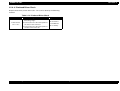
1.6 Initialization
Power-on initialization
The initialization of this level is activated by power-on or cold-reset
command (remote RS command).
This initialization is;
to initialize the printer mechanism.
to execute Operator initialization.
Operator initialization
The initialization of this level is activated by -INT signal (negative
pulse).
This initialization is;
to clear the all buffers of data.
to cancel the download character definition.
to make the printer stand-by state, if no errors occur.
to execute Software initialization.
Software initialization
The initialization of this level is activated by the control code ESC@.
This initialization is;
to clear the unprinted data.
to make the printer’s setting defaults.
Product Description
Initialization
35
LX-300+
Revision A
Cut sheet (multi part)
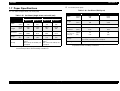
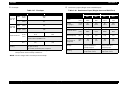
1.7 Paper Specifications
Table 1-36. Cut Sheet (Multi part)
Cut sheet (single sheet, not multi part)
Table 1-35. Cut Sheet (single sheet, not multi part)
Manual insertion
Minimum
Maximum
CSF single-bin
Minimum
(inch)
(mm)
(3.9)
100
(10.1)
(257)
Length
(inch)
(mm)
(3.9)
100
(14.3)
(364)
Maximum
(3.9)
100
(10.1)
257
(7.2)
182
(8.5)
216
Copies
Length
(inch)
(mm)
(3.9)
100
(14.3)
364
(10.1)
257
(14.0)
356
Total
Thickness
Thickness
(inch)
(mm)
(0.0025)
0.065
(0.0055)
0.14
(0.0028)
0.07
(0.0055)
0.14
(g/m2)
(lb.)
52
(14)
90
(24)
64
(18)
90
(24)
Weight
Quality
Plain paper, Reclaimed
paper
Not curled, not folded, not
crumpled
Plain paper, Reclaimed
paper
Not curled, not folded, not
crumpled
NOTE: Printing on reclaimed paper is available only under
normal temperature and humidity conditions.
Product Description
Maximum
Width
(inch)
(mm)
Width
Minimum
Weight
(one sheet of
multipart)
1 original + 4 copies
(inch)
(mm)
(0.0047)
0.12
(0.015)
0.39
(g/m2)
(lb.)
52
(14)
90
(24)
Quality
Plain paper, Reclaimed paper
Not curled, not folded, not crumpled.
Jointing
Line glue at the top or one side of form.
NOTE: Printing on reclaimed paper is available only under normal
temperature and humidity conditions.
Paper Specifications
36
LX-300+
Revision A
Envelope
Continuous paper (Single sheet and Multipart)
Table 1-37. Envelope
Minimum
Envelop
(No. 6)
(6.5)
165
(inch)
Length
(mm)
(3.6)
92
Width
(inch)
(mm)
(9.5)
241
Length
(inch)
(mm)
(4.1)
105
Envelop
(No. 10)
(inch)
(mm)
(g/m2)
(lb.)
Quality
(0.0063)
0.16
(0.0205)
0.52
The difference of thickness at the printable area is
within 0.25mm (0.0098 inch).
45
(12)
90
(24)
BOND paper, PLAIN paper or AIR MAIL
No glue at a flap
Not curled, not folded, not crumpled
NOTE: Printing on reclaimed paper is available only under normal
temperature and humidity conditions.
Bottom Entry
Min.
Max.
Min.
Max.
Width
(inch)
(mm)
(4)
101.6
(10)
254
(4)
101.6
(10)
254
Length
(one page)
(inch)
(mm)
(4)
101.6
(22)
558.8
(4)
101.6
(22)
558.8
Copies
Total Thickness
Weight
Rear Entry
Maximum
(inch)
(mm)
Width
Table 1-38. Continuous Paper (Single sheet and Multi Part)
1 original + 4 copies
1 original + 4 copies
Total Thickness
(inch)
(mm)
(0.0025)
0.065
(0.015)
0.39
(0.0025)
0.065
(0.015)
0.39
Weight
(not multipart)
(g/m2)
(lb.)
52
(14)
82
(22)
52
(14)
82
(22)
Weight
(one sheet of
multipart)
(g/m2)
(lb.)
40
(12)
58
(15)
40
(12)
58
(15)
Quality
Plain paper, Reclaimed
paper, Carbonless
multipart paper
Plain paper, Reclaimed
paper, Carbonless
multipart paper
Jointing
Point glue or paper
staple (both sides)
Point glue or paper
staple (both sides)
NOTE: Set the longer side of envelope horizontally.
Product Description
Paper Specifications
37
LX-300+
Revision A
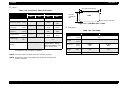
Labels
63.5 mm (2.5 inch) min.
Table 1-39. Continuous Paper with Labels
Rear Entry
Min.
Max.
---
Label size
Base sheet width
(inch)
(mm)
Base sheet length
(one page)
(inch)
(mm)
Base sheet
thickness
(inch)
(mm)
Total thickness
(inch)
(mm)
Label weight
Bottom Entry
(g/m2)
(lb.)
Quality
Min.
Max.
See the figure below.
---
(4)
101.6
(10)
254
---
(4)
101.6
(22)
558.8
---
---
(0.0028)
0.07
(0.0035)
0.09
---
---
(0.0063)
0.16
(0.0075)
0.19
-----
AVERY CONTINUOUS
FORM LABELS, AVERY
MINI-LINE LABELS or the
same quality labels
NOTE: Printing on labels is available only under normal
temperature and humidity conditions.
Label
R_2.5 mm (0.1 inch) min.
Figure 1-8. Printable Area - Label
Roll paper
Table 1-40. Roll Paper
Minimum
Maximum
Width
(inch)
(mm)
(8.5)
216
Length
(inch)
(mm)
---
Thickness
(inch)
(mm)
(0.0028)
0.07
(0.0035)
0.09
Weight
(g/m2)
(lb.)
52
(14)
82
(22)
64
(17)
---
---
23.8 mm
(15/16inch)
min.
Quality
Plain paper, Not curled, not folded, not crumpled
NOTE: The base sheet of labels must be continuous paper.
NOTE: Continuous paper with labels should be inserted from the
bottom entrance.
Product Description
Paper Specifications
38
LX-300+
Revision A
1.8 Physical Specifications
Physical Specifications (Without pull tractor)
Dimensions:
366 x 275 x 159 mm (WxDxH)
Mass:
Approx. 4.4 kg
Appearance:
See the figure below.
Physical Specifications (CSF)
Dimensions:
366 x 441 x 370 mm (WxDxH)
Mass:
Approx. 4.6 kg
Appearance:
See the figure below.
Figure 1-10. Appearance With CSF
Figure 1-9. Appearance Without Pull Tractor
Product Description
Physical Specifications
39
LX-300+
Revision A
1.9 Accessories
Table 1-41. Enclosed Parts
Enclosed Items
Quantity
User's manual
1
Driver disk
1
Ribbon cartridge (Black)
1
Power supply cable (230 V Version)
1
Table 1-42. Expendables
Enclosed Items
Description
Ribbon cartridge (Black)
#8750
Ribbon pack (Black)
#8758
Ribbon cartridge (Color)
S015073
Table 1-43. Options
Unit
Description
Cut sheet feeder
C80637*
Pull tractor unit
C80030*
Roll paper holder
#8310
Color upgrade kit
C83208*
Product Description
Accessories
40
CHAPTER
2
OPERATING PRINCIPLES
EPSON LX-300+
Revision A
2.1 Overview
LX-300+ consists of the printer mechanism and electric circuit boards.
Power Supply
Board
Main Board
C294MAIN
Printer
Mechanism
M-M310
C294PSB/PSE
Panel Board
C294PNL
Figure 2-1. Component Unit
Printer mechanism:
M-3M10
Circuit board
Main (control circuit):
C294MAIN Board
Power:
C294PSB / C294PSE Board
Panel:
C294PNL Board
The following sections describe the operating principles of each unit.
Operating Principles
Overview
42
EPSON LX-300+
Revision A
2.2 Printer Mechanism (M-3M10)
Platen gap adjustment mechanism
The following is main components of the LX-300+ printer mechanism.
Paper feed mechanism
Adjust lever, Platen gap detector
PF motor, rear paper end (RPE)detector, bottom paper end (BPE)
detector
Printhead
Carriage mechanism
Carriage (CR) motor, Carriage home position (HP) detector
Release mechanism
Release detector (REL)
Ribbon mechanism
Color ribbon drive mechanism (option)
Tractor
Rear paper end detector
Release detector
Release mechanism
Bottom paper end detector
PF motor
Platen
Carriage guide shaft
Timing belt
Adjust lever
Ribbon
Carriage motor
Carriage
Platen gap detector
Ribbon Mechanism
Carriage home position detector
Printhead
Figure 2-2. Printer Mechanism Block Diagram
Operating Principles
Printer Mechanism (M-3M10)
43
EPSON LX-300+
Revision A
2.2.1 Printhead
The table below shows the printhead specifications.
Table 2-1. Printhead Specifications
Item
Specification
Number of wires
9
Diameter of wire
φ0.29 mm
Wire configuration
See the figure below.
Note: The figure is seen from the back of the
head facing printing side.
Direct current coil resistance
33.3 ±3.3 Ω (25°C)
Head drive method
Rated voltage drive
Head drive voltage
35+2.1/-3.5 V
• Normal: 0.75 A (Standard)
• Copy:
0.85 A (Standard)
1.0 A (Maximum)
• Normal: 1350Hz or less
• Copy:
1350Hz or less
• Black ribbon: 0.2 billion stroke/ wire or
more
• Color ribbon: 0.1 billion stroke/ wire or
more
• Temperature: 5 to 55°C
• Humidity:
10 to 85%
Peak current
Head drive frequency
Head life
Environmental condition
Operating Principles
Figure 2-3. Wire Configuration
2.2.1.1 Buzzer Function
This printhead also works as a buzzer. The table below is buzzer specification.
Printer Mechanism (M-3M10)
Table 2-2. Buzzer Function -- Specification
Item
Specification
Head voltage
35 +2.1 / -3.5 V
Drive frequency
2kHz, 1.5kHz
44
EPSON LX-300+
Revision A
2.2.2 Carriage Mechanism
The following is the components of the LX-300+ carriage mechanism and its
explanation. (Refer to Figure 2-2, "Printer Mechanism Block Diagram")
Carriage:
Mounts the printhead.
CR motor:
Drives carriage to the printing column direction.
Timing belt:
Transfers the drive from the CR motor to the carriage.
Carriage guide shaft: Shifts the carriage parallel to the platen.
HP detector:
Detects carriage home position.
CR MOTOR
This printer uses stepping motor for CR motor. Open loop control switches
the phases according to the setting period and this mechanism enables the
carriage to move until the appointed position. The table below is the CR
motor specifications.
Table 2-3. CR Motor Specifications
Item
Specification
Motor type
2-phase/200-pole hybrid stepping motor
Coil resistance
5.7Ω±10% (25°C)
Control method
Bi-polar drive
Phase drive
2-2 phase, 1-2 phase, W1-2 phase
Drive voltage
36.75 ±1.75 V
CR feed pitch
Minimum Resolution:
0.212 mm (1/120”) (1-2 phase, 2 pass)
Operating Principles
Printer Mechanism (M-3M10)
45
EPSON LX-300+
Revision A
The following table shows the various carriage speed modes.
Table 2-4. Carriage Speed Mode
Carriage
speed
mode
CR drive
frequency
[Hz]
A
3600
B
3375
C
D
Printing
mode
2700
2250
Phase
drive
[pps]
Current limit (A/phase)
Front
rush
High
speed
Normal
speed
Low
speed
Rear
rush
Color
2-2
0.79
0.79
0.70
0.70
0.70
BW
2-2
0.70
0.59
0.59
0.59
0.59
Color
2-2
0.79
0.79
0.70
0.70
0.70
BW
2-2
0.70
0.59
0.59
0.59
0.59
Adjacent
dot
resolution
[dpi]
Head drive
frequency
[Hz]
45
1350
48
1350
Carriage
speed mode
at power
down
High or
low
speed
printing
High speed draft
10cpi
C
{
High speed draft
12cpi
E
{
F
{
F
{
G
x
Printing speed
High speed draft
15cpi
Draft 10cpi
Bit image 60 dpi
Color
2-2
0.79
0.79
0.70
0.70
0.70
BW
2-2
0.70
0.59
0.59
0.59
0.59
Color
2-2
0.79
0.79
0.70
0.70
0.70
1440/21
1286
High speed draft
17cpi
BW
2-2
0.70
0.59
0.59
0.59
0.59
72
1350
Bit image 72 dpi
Color
2-2
0.79
0.79
0.70
0.70
0.70
80
1200
Bit image 80 dpi
60
1350
Draft 12cpi
BW
1-2
0.65
0.65
0.59
0.59
0.59
90
1350
High speed draft
20cpi
Draft 15cpi
Bit image 90 dpi
1350
Both
1-2
0.65
0.65
0.59
0.59
0.59
120
1350
Draft 20/17cpi
NLQ 10cpi
Bit image 120 dpi
I
x
G
1125
Both
1-2
0.65
0.65
0.59
0.59
0.59
144
1350
Bit image 144 dpi
I
x
H
900
Both
1-2
0.65
0.65
0.59
0.59
0.59
180
1350
NLQ 15cpi
I
x
I
675
Both
1-2
0.65
0.65
0.59
0.59
0.59
240
1350
NLQ 17/20cpi
J
x
J
450
Both
1-2
0.65
0.65
0.59
0.59
0.59
-
x
E
1800
F
Operating Principles
Printer Mechanism (M-3M10)
46
EPSON LX-300+
Revision A
CARRIAGE HOME POSITION (HP) DETECTOR
2.2.3 Ribbon Mechanism
The table below is the HP detector specifications.
2.2.3.1 Ink Ribbon Shifting Mechanism
Ink ribbon shifting mechanism: CR motor drives timing belt and the timing
belt driven pulley drives the ribbon shifting gears.
Table 2-5. HP detector Specifications
Item
Specification
Method
Mechanical contact method
2.2.3.2 Color Ribbon Driving Mechanism (Option)
Switching rate
0.6 to 1.0 mA, 5 VD±5%
• out of HP: close
• within HP: open
Color ribbon driving mechanism: shifts the color ribbon up and down to
change the color area of the ribbon to be printed.
Switching mode
HP detector detects the signal right after when the CR motor switches the
phase.
2.2.2.1 High speed skip method
At no-printing area, the carriage moves at high speed compared to the
normal carriage speed at printing. This is called carriage control.
Color ribbon mechanism consists of the color shift (CS) motor, CS cam,
ribbon detector, CS lever assembly and color cartridge holder. Color ribbon is
installed on the color cartridge holder.
When CS motor revolves, 1) the pinion revolves CS cam, 2) the CS lever
assembly on the CS cam shifts the color cartridge holder up and down and 3)
drives ribbon up and down.
Table 2-6. CS Motor Specifications
Item
Motor type
2-phase/48-pole PM stepping motor
Coil resistance
150Ω ±5% (25°C, per 1 phase)
Control method
uni-polar rated voltage drive
Phase drive
2-2 phase
Drive voltage
36.75 ± 1.75 VDC
• Operating, peak current: 245 mA
• Non-operating:
20 mA
500 pps
Consuming current
Drive frequency
Operating Principles
Specification
Printer Mechanism (M-3M10)
47
EPSON LX-300+
Revision A
RIBBON CARTRIDGE DETECTOR
Color ribbon drive circuit
Ribbon detector detects if the color ribbon is installed or not.
Detect Timing
When the power is applied.
Ribbon detector
When recovering from the economy mode.
When the printing is started.
Table 2-7. Ribbon Detector Specifications
Item
CS motor
CS cam
CS lever assembly
Specification
Method
Mechanical contact method
Switching rate
0.6 to 1.0 mA
• Color ribbon cartridge is installed: High
• Black ribbon cartridge is installed or
ribbon is not installed: Low
Switching mode
Color ribbon
CS lever assembly
Black
Cyan
Magenta
Yellow
AVOID COLOR FROM MIXING
Color cartridge holder
To avoid the color area on the ribbon from mixing up each other or minimize
the color mixing up, the printing is done by the following order when printing
green, violet and orange.
Table 2-8. Color Printing Order
CS motor, pinion
CS cam
Figure 2-4. Color Ribbon Driving Mechanism
Operating Principles
Printer Mechanism (M-3M10)
Color
First color
Second color
Green
Yellow
Cyan
Orange
Yellow
Magenta
Violet
Magenta
Cyan
48
EPSON LX-300+
Revision A
COLOR MECHANISM INITIALIZATION
PLATEN GAP (PG_SW) DETECTOR
The printer mechanism initializes when the power is applied or when
recovering from the energy saving mode.
The following is PG_SW specification.
Table 2-9. PG_SW Detector Specifications
Color mechanism initialization
Color mechanism initialization shifts color mechanism for the black
ink area to be at the home position. Color mechanism initialization
shifts the carriage at the same time to prevent the ribbon from
hanging on the printhead.
When the buffer is cleared or when the printer is under the pause
condition, the color mechanism initializes and waits for the next
printing command.
Item
Specification
Method
Mechanical contact method
Switching rate
0.6 to 1.0 mA, 5 VD±5%
• PG=0: close
• PG=0-4: open
Switching mode
Adjust lever
Carriage guide shaft
2.2.4 Platen Gap Adjustment Mechanism
This mechanism is to adjust the distance between the platen and the
printhead (platen gap) according to the paper thickness.
The following is the components of the LX-300+ platen gap adjustment
mechanism and its explanation. (Refer to Figure 2-5, "Platen Gap Adjustment
Mechanism")
Carriage:
Carriage
Parallelism adjust
bushing
Parallelism adjust
bushing
PG_SW
Mounts the printhead.
Carriage guide shaft: Shifts the carriage horizontally.
Adjust lever and Parallelism adjust bushing:
Installed at the both ends of the carriage guide shaft
Platen gap detector (PG_SW)
Platen gap
Carriage guide shaft is eccentric toward the adjust lever rotating center. Due
to this, when rotating the adjustment lever back and forth, the printhead shifts
toward and against the platen to adjust the platen gap. When printing on thick
paper such as postcards and envelops, set the adjust lever over the 1st level.
PG detector shifts the printer to the copy mode from the printing mode.
Printing speed will be lowered but it prevents wire from breaking off.
Printer mechanism
Printhead
Adjust lever
Platen
Carriage
Carriage guide shaft
Figure 2-5. Platen Gap Adjustment Mechanism
Operating Principles
Printer Mechanism (M-3M10)
49
EPSON LX-300+
Revision A
2.2.5 Paper Feed Mechanism
PF MOTOR
This mechanism consists of paper feed motor (PF motor), paper feed gears,
platen, rear paper end detector, bottom paper end detector and push tractor
unit. (Refer to Figure 2-2, "Printer Mechanism Block Diagram")
LX-300+ uses the stepping motor for PF motor. Open loop control switches
the phase according to the
LX-300+ uses stepping motor for PF motor. Open loop control switches the
phases according to the setting period and this mechanism loads and carries
paper to the appointed position and eject paper.
Paper Feed Method
Friction feed
Push tractor feed
The table below is the PF motor specifications.
Uses standard push tractor
Table 2-10. PF Motor Specifications
Push-pull tractor feed
Uses standard push tractor + Option tractor
Item
Specification
Motor type
2-phase/96-pole Hybrid stepping motor
Coil resistance
16.0Ω ±10% (25°C, per 1 phase)
Control method
bi-polar rated current drive
Simple CSF (option)
Phase drive
1-2 phase, W1-2 phase
Tractor (standard)
Drive voltage
36.75 ± 1.75 VDC
(This voltage is added to driver.)
Drive current
0.1 to 0.9A
Paper feed pitch
Minimum Resolution:
0.059 mm (1/432”) (1-2 phase, 2 pass)
Pull tractor feed
Replace the standard push tractor with option tractor
Feeder
Push / Pull
Pull tractor (option)
Roll paper holder
Paper path
Manual loading
Rear paper load, top paper load
CSF
Rear paper load, top paper load
Push tractor
Rear paper load, top paper load
Pull tractor
Rear / Bottom paper load, top paper load
Auto loading
When loading paper manually, push paper between the platen and
the driven paper load roller. Paper will be loaded automatically.
Operating Principles
Printer Mechanism (M-3M10)
50
EPSON LX-300+
Revision A
2.2.5.1 Page Length Measurement
RPE DETECTOR
RPE detector is installed on the paper path at the back of the printer. The table
below shows the RPE detector specifications.
Value = [The number of paper feed pulse from the paper top (top margin:
4.2mm) until RPE detector detects paper end] + [forms over-ride specified
paper feed pulse] - [adjustment value]
Table 2-11. RPE Detector Specifications
Item
Specification
Method
Mechanical contact method
Switching rate
0.6 to 1.0 mA, 5 VD±5%
• Paper inside: open
• No paper: close
Switching mode
When CSF is used:
BPE DETECTOR
BPE detector is installed right under the platen. The table below shows the
BPE detector specifications.
Table 2-12. BPE Detector Specifications
Item
Specification
Method
Mechanical contact method
Switching rate
0.6 to 1.0 mA, 5 VD±5%
• Paper inside: open
• No paper: close
Switching mode
Operating Principles
Page length measurement is a process to convert the following value to the
number of printing lines.
The uncertainty of the paper end detector may vary the number of
printing lines within the same paper size. To avoid this, when CSF is
used, page length measurement calculates the printable lines and if
the paper is longer than the printable lines, the number of printing
line is considered the printable lines (fixed value).
When paper is shorter than the printable lines, the printer prints the
fixed number of lines by forms over-ride function (which allows the
fixed number of lines to be printed even when RPE detector detects
paper end).
When CSF is not used:
When loading paper manually or when tractor feed is used, the
number of printing lines of paper end is determined by forms override function after BPE or RPE detector detects paper end.
Printer Mechanism (M-3M10)
51
EPSON LX-300+
Revision A
2.2.6 Release Mechanism
The table below shows the release detector specifications.
This mechanism switches the flow of PF motor driving forth between to the
friction feed and to the tractor feed.
Compression spring
Plain
washer
Tractor gear
Table 2-13. Release Detector Specifications
Item
Mechanical contact method
Switching rate
0.6 to 1.0 mA, 5 VD±5%
• Friction: open
• Tractor: close
Switching mode
Release lever
Paper
advance
reduction
gear
Release
detector
Specification
Method
2.2.7 Other Special Functions
2.2.7.1 Energy saving mode
This function saves electric consumption when the printer is in the standby
mode. This mode turns hold current of PF motor, CR motor and CS motor
OFF.
2.2.7.2 Quiet Mode
Printer mechanism
Quiet mode lowers printing temperature. When this mode is selected,
carriage speed will be lowered to the power down mode speed. Refer to
Table 2-4, “Carriage Speed Mode,” on page 46.
PF motor
Figure 2-6. Release Mechanism
Release mechanism consists of the following.
Release lever:Shifts tractor low speed gears back and forth.
Tractor gear
Paper advance reduction gear:Transfers the PF motor driving forth to
the tractor gear.
Release detector (REL):Detects the release lever position.
Operating Principles
Printer Mechanism (M-3M10)
52
EPSON LX-300+
Revision A
2.3 Electric Circuit Operating Principles
2.3.1 MAIN Board (Control Board) Electric Circuit
The figure below is the MAIN board block diagram.
Control Panel
HP sensor
RPE Sensor
Release Sensor
BPE Sensor
PG Sensor
Figure 2-7. MAIN Board Block Diagram
Operating Principles
Electric Circuit Operating Principles
53
EPSON LX-300+
Revision A
2.3.2 C294PSB / C294PSE Board
Table 2-14. Main Elements
Elements
CPU
G/A *
PROM
Location
IC3
IC6
IC7
Function
RISC C33208 CPU, QFP 128 pin
• Outside clock 19.66 MHz/
Inside clock 39.32 MHz
• 8KBRAM built-in
• Various DMA
• A/D converter
Approximately 21000 gates, QFP 160 pin
• Bit manipulation
• Clock control
• interface control (IEEE1284/Type-B I/F)
• Input Buffer control
• Motor control
• Head control
4M / 8Mbit, DIP 40 / 42 pin
• Stores firmware
• CG
LX-300+ generates power supply by 2 power supply boards: C294PSB (100V)
and C294PSE (200V). The table below shows the power supply boards input
voltage specifications.
Table 2-15. Power Supply Boards Input Voltage Specifications
Circuit
Input voltage
Fuse specification
C294PSB
99 - 132VAC
ULTSC-2.5A-NI
C294PSE
198 - 264VAC
HT 1.25A
2.3.2.1 Electric Circuit
The power supply board supplies two types of power for control circuit and
driving mechanism. The table below shows output voltage and its use.
Table 2-16. Output Voltage and its Use
DRAM
IC8
1/2/4M bit switching method, SPJ package 40 pin
• Various buffer, work area
EEPROM
IC5
AT93C46, 1kbit, SOP 8pin
• Stores default value and various parameter
RESET IC
IC4
M62030 (SANYO), 8 pin
• CPU and G/A reset
CR Motor Driver
IC9
LB1847 (SANYO)
PF Motor Driver
IC10
LB1847 (SANYO)
Serial I/F Transceiver
IC2
HIN202CBN or equivalent
Regulator IC
IC11
BA033 (ROHM) or equivalent
• Generates 3.3V logic voltage
Regulator IC
IC12
PD494 or equivalent
• 95V rated voltage circuit
• Detects over voltage (over 150V) and sends
OFF signal to the power supply boards.
Thermistor
TH1
Measures temperature of the motor driver.
Output voltage
Use
35 V +5%/ -10%
Drive
5 V ± 5%
Logic Voltage*
NOTE: *: Core voltage of CPU and G/A is 3.3V and it is generated by
the regulator IC on the MAIN board form +5VDC.
NOTE: *: CPU and G/A will be changed to 2in1 type later.
Operating Principles
Electric Circuit Operating Principles
54
CHAPTER
3
TROUBLESHOOTING
EPSON LX-300+
Revision A
3.1 Overview
Troubleshooting
This chapter describes how to troubleshoot problems when any problems
occurred to the printer.
Initialization
Check
W A R N IN G
C A U T IO N
Never touch printhead and any motors right after printing
since they are highly heated.
When disassembling the printer, be sure to disconnect the
power cable and remove the interface cable.
Be sure to use specified tools for servicing to maintain the
Check performance by
self-check function.
Does any
trouble occur?
quality.
Make sure to apply specified oil, grease and glue.
Perform adjustment as specified.
Identify problems
from symptoms.
Perform
maintenance.
Figure3-1. Troubleshooting Procedure
Troubleshooting
Overview
56
EPSON LX-300+
Revision A
3.2 Troubleshooting
3.2.2 Check Performance By Self-Check Function
3.2.1 Initialization Check
Before troubleshooting, check the following basic items.
1.
When printer can perform printing, perform self-test and check if any
troubles occur.
2.
When the printer cannot perform any printing, check the setting by
“Default Setting”. (Refer to Chapter 1.)
3.
Check if the outside and inside the printer is noticeably dirty or if any
parts are broken. If there is dirt, perform cleaning referring to Chapter 6
“Maintenance”.
LX-300+ has self-check function and it supervises the printer condition
constantly. If any problem occurs, it indicates error by indicator LED and in
some cases it notifies error to the operator by beeping the buzzer. Identify
error cause, referring to the indication first. If error is not solved, perform unit
repair.
3.2.2.1 Indicator LED
The table below shows the indicator LED and the printer condition.
Table 3-1. Indicator LED
Pause
Paper Out
Front
Buzzer
Pause
ON
-
-
-
Make sure each harness is connected properly.
Paper Out Error
ON
ON
-
Shoot beep x3
Make sure no remarkable friction among printer mechanism gears. Make
sure all gears are linked properly.
Release Lever Error
ON
-
-
Long beep x5
Paper Eject Warning
ON
BLINK
-
-
6.
Make sure there is no dirt nor scratch on rollers inside the printer.
MICRO Adjust
BLINK
-
-
-
7.
Perform EEPROM clear as needed. Inside setting is reset to the factory
default setting. (Refer to Chapter 1.)
Tear Off
-
-
According to
LED On/Off
combination
-
Font Select
-
-
According to
LED On/Off
combination
-
Fatal Error
BLINK
BLINK
BLINK
-
4.
5.
Printer Condition
Paper Out Error
This error will be indicated when printer fails to feed paper or paper is
run out.
Solution
Set paper properly and try paper feed again.
Troubleshooting
Troubleshooting
57
EPSON LX-300+
Revision A
Release Lever Error
This error will be indicated when wrong release lever operation is
performed. For example, if you change the release lever setting when
the printer already starts feeding paper, this error will be generated.
Solution
Reset the release lever.
3.2.3 Identify Problems From Symptoms
This section procedure to identify the problems from the abnormal
symptoms. Basically unit repair or replacement should be performed, but if
necessary parts level replacement should be performed.
Find your symptom in the table below and check the corresponding table.
Fatal Error
Table 3-2. Symptoms and Solutions
This error will be indicated when;
-carriage error is occurred
-input voltage is abnormal
-hardware problem is occurred
Symptom
When power is
applied, the printer
does not operate.
Solution
If it is carriage error, check if there is no obstacles for carriage to
move.
If it is input voltage problem, check power supply voltage.
If it is hardware problem, check machine and electric circuit.
When power is
applied, the printer
becomes fatal error.
Self-test print is
abnormal.
Paper feed is
abnormal.
Control panel and
switches do not
operate properly.
Printing operation is
abnormal when it is
on-line.
Troubleshooting
Troubleshooting
Problems
Check Table
Control panel LED does not
operate at all.
Table 3- 3 on page 59
Printer mechanism does not
operate at all.
• Control panel indicates fatal
error.
• The printer indicates error after
initialization.
• Platen gap is not correct.
• Printhead and ribbon mask is
abnormal or their life are over.
• Vertical direction printing
quality is abnormal.
• Paper feed operation is not
performed.
• Paper switching is abnormal.
• Line feed is not equal.
• Skew is generated.
• LED indication is abnormal.
• Cannot input from switches.
Table 3- 4 on page 59
• Self-test is normal, but the
printing from host computer is
abnormal.
Table 3- 5 on page 59
Table 3- 6 on page 60
Table 3- 7 on page 60
Table 3- 8 on page 60
Table 3- 9 on page 61
58
EPSON LX-300+
Revision A
Table 3-4. Printer Mechanism Does Not Operate.
Table 3-3. Control Panel LED Does Not Light On.
Cause
Check Point
Y/N
Solution
Blowout of a fuse
on the power
board.
Is a fuse on the
power board blew
out?
YES
Check the electric circuit and
printer mechanism. If there is
no short circuit, replace the
fuse.
Connector is not
connected to the
power board.
Are connectors
connected to the
power board
properly?
NO
Replace the power board.
Power switch is
defective.
Is conductivity of
the switch is OK?
YES
Power board is
defective.
Are +5VDC and
+35VDC OK when
the power is on?
NO
Is CN8 connected
properly?
NO
Power board and
the main board
are not connected
properly.
Main board is
defective.
Control panel
harness is not
connected
properly.
Control panel
board or harness
is defective.
Is the harness of
the control panel
connected
properly?
-
Cause
Replace the power board.
Check Point
Y/N
Are all connectors
connected
properly?
NO
Connect them properly.
Main board is
defective.
-
-
Replace the main board.
Printer mechanism
is defective.
-
-
Replace the printer
mechanism.
Any of CN3 to
CN12 is not
connected to the
main board
properly.
Table 3-5. When Power is Applied, the Printer Becomes Fatal Error.
-
NO
Cause
Replace the power board.
CR motor harness
is not connected
properly.
Connect CN8 properly.
Replace the main board.
Connect the harness
properly.
CR motor is
defective.
HP detector
harness is not
connected
properly
HP detector is
defective.
-
Replace the control panel.
Power board is
defective.
-
Troubleshooting
Solution
Troubleshooting
Check Point
Is CR motor
harness CN10
connected
properly?
Is HP detector
harness CN3
connected
properly?
Is power voltage
normal?
-
Y/N
Solution
NO
Connect it properly.
-
NO
Replace the CR motor.
Connect it properly.
-
Replace the HP detector.
NO
Replace the power board.
-
Replace the main board and
printer mechanism.
59
EPSON LX-300+
Revision A
Table 3-7. Paper Feed is Abnormal.
Table 3-6. Self Test Print is Abnormal.
Cause
Any of CN3 to
CN12 is not
connected to the
main board
properly.
Printhead driver is
defective.
Bi-d is not correct.
Printhead is
defective.
Head FFC is not
connected
properly or broken.
Check Point
Are all
connectors
connected
properly?
-
Y/N
NO
Connect them properly.
-
Replace the main board.
Are rows aligned
properly when bidirectional
printing is
proceeded?
NO
Is there any dot
missing?
YES
Is printing too
light / weak?
YES
Adjust the platen gap.
Is there any dirt
on printed
documents?
YES
Ribbon mask is
defective.
Is there any dirt
on printed
documents?
YES
Ribbon
mechanism is
defective.
Is ribbon
advanced
properly?
NO
-
-
Y/N
Solution
NO
Replace the sensor.
YES
Check the connection to the
main board.
Switch the
release lever. Is
the paper loading
direction
switched?
NO
Replace the printer
mechanism or check the
connection.
Can the release
lever be
switched?
NO
Replace the release sensor or
check the connection.
Printer mechanism
paper loading
mechanism is
defective.
When the power
is off, can the
printer feed
paper by rotating
the platen knob
manually?
NO
Replace the printer
mechanism or paper loading
mechanism parts.
PF motor is
defective.
Is PF motor
normal?
NO
Replace the PF motor.
RPE detector or
BPE detector is
defective or not
connected
properly.
Paper switching
mechanism is
defective.
Replace the printhead.
Replace the head FFC.
Printer mechanism
is defective.
Cause
Adjust Bi-D.
YES
Platen gap is not
correct.
-
Solution
Adjust the platen gap.
PF motor driver is
defective.
Replace the ribbon mask.
Replace the ribbon mechanism
parts.
Replace the printer
mechanism.
Check the
sensors. Is there
any abnormality?
-
-
Replace the main board.
Table 3-8. Control Panel and Switches Do Not Operate.
Cause
Check Point
Y/N
Switch is defective.
Is conductivity of
the switch is OK?
NO
Replace the control panel.
Connect the
control panel
harness.
Control panel
harness is
connected
properly?
NO
Connect it properly.
Control panel
board is defective
or the harness is
defective.
Troubleshooting
Check Point
Troubleshooting
-
-
Solution
Replace the control panel.
60
EPSON LX-300+
Revision A
Table 3-9. Printing Operation is Abnormal When it is On-Line.
(Self-Test is Normal.)
Cause
Check Point
Y/N
Solution
Initial setting is
wrong.
Check the initial
setting with the
default setting. Is it
OK?
NO
Reset the setting or use the
EEPROM clear to reset setting
to the default.
Interface cable
is not
connected
properly.
Are cables
connected
properly?
NO
Connect them properly.
This section describes the checking method of the printhead, motors and
sensors to find the defective units and parts.
W A R N IN G
When repairing the unit, make sure to turn the printer off and
plug off the power cable except when this manual specifies to
keep the power on.
3.2.4.1 Printhead Check
Interface cable
is defective.
-
-
Replace the interface cable.
Main board is
defective.
-
-
Replace the main board.
Firmware is
defective.
3.2.4 Unit and Parts Check
By measuring the direct current resistance of the printhead coil, you can
check if it is all right.
Table 3-10. Printhead Coil Resistance
Is the firmware
version latest?
NO
Replace the firmware.
Item
Printhead
Operation
1. Set the multimeter to the resistance
measuring range.
2. Connect the one side of the probe to C.
3. Connect the other side of the probe to
corresponding head pin No.
Specification
33.3 ± 3.3Ω
(at 25°C/phase)
Looked From Point A
Figure3-2. Head Coil Pin No.
Troubleshooting
Troubleshooting
61
EPSON LX-300+
Revision A
3.2.4.2 Motor Check
3.2.4.3 Sensor Check
By measuring the direct current resistance of the motor coil, you can check if
the motor is all right.
When the sensor is connected mechanically, you can check the sensor by its
conductivity.
Table 3-11. Motor Check
Table 3-12. Sensor Check
Item
CR motor
PF motor
CS motor
(option)
Operation
Specification
1. Set the multimeter to the resistance measuring
range.
5.7Ω ±10%
2. Connect the one side of the probe to 1 or 2 pin. (at 25°C/phase)
3. Connect the other side of the probe to 3 or 4 pin.
1. Set the multimeter to the resistance measuring
range.
16.0Ω ±10%
2. Connect the one side of the probe to 1 or 2 pin. (at 25°C/phase)
3. Connect the other side of the probe to 3 or 4 pin.
1. Disassemble the CS unit.
2. Set the multimeter to the resistance measuring
range.
150Ω ± 5%
3. Connect the one side of the probe to brown
(at 25°C/phase)
[TBD] harness.
4. Connect the other side of the probe to other 4
harness.
Troubleshooting
Item
Operation
1. Set the multimeter to the
resistance measuring range.
2. Connect the one side of the probe
HP detector
to CN3 1 pin.
3. Connect the other side of the
probe to CN3 2 pin.
1. Set the multimeter to the
resistance measuring range.
2. Connect the one side of the probe
RPE detector
to CN4 1 pin.
3. Connect the other side of the
probe to CN4 2 pin.
1. Set the multimeter to the
resistance measuring range.
2. Connect the one side of the probe
Release detector
to CN5 1 pin.
3. Connect the other side of the
probe to CN5 2 pin.
1. Set the multimeter to the
resistance measuring range.
2. Connect the one side of the probe
BPE detector
to CN6 1 pin.
3. Connect the other side of the
probe to CN6 2 pin.
1. Set the multimeter to the
resistance measuring range.
2. Connect the one side of the probe
PG detector
to CN3 7 pin.
3. Connect the other side of the
probe to CN3 7 pin.
Troubleshooting
Specification
When switching the
sensor actuator, it
should be switched
ON/OFF.
When switching the
sensor actuator, it
should be switched
ON/OFF.
When switching the
sensor actuator, it
should be switched
ON/OFF.
When switching the
sensor actuator, it
should be switched
ON/OFF.
When switching the
sensor actuator, it
should be switched
ON/OFF.
62
EPSON LX-300+
Revision A
3.2.4.4 Printhead Driver Check
Simple check of the printer driver (Q3 ~ Q11) can be done by the following
method.
Table 3-13. Printhead Driver Check
Item
Printer driver
(Q3 ~ Q11)
Troubleshooting
Operation
1. Set the multimeter to the resistance
measuring range.
2. Connect the one side of the probe to
the base of the transistor.
3. Connect the one side of the probe to
emitter of the transistor.
Specification
The resistance
should NOT be
“0” or infinity.
Troubleshooting
63
CHAPTER
4
DISASSEMBLY AND ASSEMBLY
EPSON LX-300+
Revision A
4.1 Overview
Table 4-1. Recommended Tools
Tools
This chapter explains the disassembly and assembly of LX-300+.
Needle-nose pliers
B740400100
Nipper
B740500100
Tweezers
B741000100
Soldering bit
B740200100
When disassembling and adjusting the printer, remove
E ring holder #2.5
B740800400
the AC cable off the socket.
Never touch the printer right after it finishes printing, for
the printhead is highly heated.
+ driver No.2
B743800200
Box driver (opposite side distance: 7mm)
B741700200
Thickness gauge
B776702201
4.1.1 Precautions
Read the precautions below before disassembling and assembling the
printer.
W A R N IN G
C A U T IO N
Part No.
For disassembly and assembly of the printer, use the tools
NOTE: All tools are available in market.
specified in this chapter.
Table 4-2.
Use the specified oil and grease.
When performing the adjustment, follow the method
Device
described in this manual.
Multimeter
4.1.2 Tools
The table below lists the tools recommended to use for disassembly and
assembly and adjustment. Use only tools specified here.
Disassembly and Assembly
Oscilloscope
Specification
50MHz
NOTE: Only component level repairing service requires oscilloscope.
Overview
65
EPSON LX-300+
Revision A
4.1.3 Service Checks After Repair
Table 4-3. Check List for Repaired Printer
Category
Before returning the printer back to the user, use the check list below to
confirm the quality of the repaired printer.
Component
Table 4-3. Check List for Repaired Printer
Component
Printhead
Item to Check
NG
Is Bi-d adjustment value correct?
OK
NG
Initial
setting
Have all user changeable
settings been reset to the default
value?
OK
NG
ROM
version
Latest ROM version ________
OK
NG
Ink ribbon
Is ribbon removed?
OK
NG
accessories
Are all the relevant parts
included in the shipment?
OK
NG
Adjustment
Check
Is dot missing?
OK
NG
Are any wires broken?
OK
NG
Version Up
Does carriage move smoothly?
CR movement is not noisy?
CR mechanism is not dirty?
CR mechanism is not oily?
OK
Is the CR motor assembly at the
correct temperature?
(Not overheating?)
OK
NG
Is paper advancing smoothly?
PF movement is not noisy?
PF mechanism is not dirty?
PF mechanism is not oily?
OK
NG
Is the PF motor assembly at the
correct temperature?
(Not overheating?)
OK
NG
Are all the types of paper fed
smoothly?
OK
NG
Does the tractor feed paper
smoothly?
OK
NG
Is the paper path clear of
obstructions?
OK
NG
Is the platen free of damage?
OK
NG
Is the ribbon mask free of
distortion?
OK
NG
Test printing Is the test printing successful?
OK
NG
Online
printing
OK
NG
Carriage
mechanism
Paper feed
mechanism
Printer
Mechanism
Paper path
Ribbon
mask
Is the online printing successful?
Disassembly and Assembly
NG
Transportation
Overview
Check
OK
Printhead
Category
Item to Check
Is the platen gap adjusted
correctly?
66
EPSON LX-300+
Revision A
4.2 Disassembly and Assembly
The figure below is the disassembly flowchart for main component.
This section explains the disassembly and assembly of LX-300+. Unless
otherwise specified, assembly can be done in the reverse order of the
disassembly procedure.
Anything that service person should pay attention to is described under
“Check Point”. Any adjustment required after assembly is described under
“Adjustment”.
When you have to remove parts that are not described in this chapter, refer to
the exploded diagram on Appendix of this manual.
C A U T IO N
START
4.2.2 "Upper Housing
Removal"
4.2.1 "Printhead
Removal"
4.2.3 "Printer
Mechanism Removal"
4.2.4 "Board Assembly
and Panel Removal"
4.2.5 "C294MAIN Board
Assembly Removal"
4.2.6 "P/S Board
Assembly Removal"
Read 4.1.1 "Precautions" before start disassembling the
printer.
Remove ink ribbon and paper before disassembling the
printer.
Flowchart 4-1. Disassembly Flowchart (Main Component)
Disassembly and Assembly
Disassembly and Assembly
67
EPSON LX-300+
Revision A
4.2.1 Printhead Removal
Printhead
1.
Remove the cover and the printer.
2.
Remove 1 screw (CPB, 3x14) securing the printhead to the carriage
assembly.
3.
Lift the printhead a little bit. Unlatch 2 hooks securing the printhead FFC
to carriage unit.
4.
Remove FFC from the printhead.
CPB (3x14)
FFC
Carriage Assembly
C A U T IO N
Check if the printer is powered off before removing the
printhead.
A D J U S T M E N T
R E Q U IR E D
When the printhead is replaced, perform the platen gap
adjustment.
Figure4-1. Printhead Removal
Disassembly and Assembly
Disassembly and Assembly
68
EPSON LX-300+
Revision A
4.2.2 Upper Housing Removal
1.
Remove platen knob, cover assembly, printer, tractor unit and paper eject
unit. Remove the color upgrade kit if it is installed.
2.
Set the release lever to the tractor feed.
3.
Remove 4 screws (CBP, 3x10) securing the upper housing to the lower
housing.
4.
Remove the upper housing.
C H E C K
P O IN T
When installing the upper housing, be sure to insert
LEDs on the panel board to the LED holes of the upper
housing.
Upper Housing
CPB (3x10)
Upper Housing
LED
Panel Board Assembly
CPB (3x10)
Figure4-2. Upper Housing Removal
Disassembly and Assembly
Disassembly and Assembly
69
EPSON LX-300+
Revision A
4.2.3 Printer Mechanism Removal
Printer Mechanism
1.
Remove the upper housing. (See 4.2.2 "Upper Housing Removal".)
2.
Remove 3 screws (CBP, 3x10) securing the upper shield plate to the lower
housing. Remove the shield cover.
Upper Shield Plate
CPB (3x10)
Main Board Assembly
CBB (3x14) with washer
CBB (3x14) with washer
Printer Mechanism
Figure4-4. Harness Removal
Figure4-3. Upper Shield Plate
3.
Remove 2 screws with washer (CBP, 3x14) securing the printer
mechanism to the lower housing.
4.
Lift the printer mechanism a little bit and remove harnesses from the
main board assembly.
Disassembly and Assembly
5.
Remove the printer mechanism.
A D J U S T M E N T
R E Q U IR E D
Disassembly and Assembly
Perform Bi-D adjustment after removing the printer
mechanism.
70
EPSON LX-300+
Revision A
4.2.4 Board Assembly and Panel Removal
4.2.5 C294MAIN Board Assembly Removal
1.
Remove the upper housing. (See 4.2.2 "Upper Housing Removal".)
1.
Remove the upper housing. (See 4.2.2 "Upper Housing Removal".)
2.
Remove the panel FFC from the connector of panel board assembly.
2.
3.
Remove 3 screws (CBP, 3x10) securing the panel board assembly to the
lower housing.
Remove the printer mechanism. (See 4.2.3 "Printer Mechanism
Removal".)
3.
Remove 2 hexagon nuts securing the serial interface connector to the
lower shield plate.
4.
Remove the serial interface connector from the installation hole of the
lower shield plate.
5.
Remove 2 CP (M3x6) securing the parallel interface to the lower shield
plate.
6.
Remove the option FFC and panel FFC from CN12 and CN13 on the board.
7.
Remove the harness from the P/S board assembly from CN8.
8.
Remove 3 screws (CBP, 3x10) securing the main board assembly to the
lower housing.
4.
Remove the panel board assembly from the lower housing.
A D J U S T M E N T
R E Q U IR E D
Panel Board Assembly
When the main board assembly is replaced, perform
destination setting and Bi-D adjustment.
Panel FFC
CPB (3x10)
Figure4-5. Board Assembly and Panel Removal
Disassembly and Assembly
Disassembly and Assembly
71
EPSON LX-300+
Revision A
4.2.6 P/S Board Assembly Removal
Lower Shield Plate
CP (M3x6)
Hexagon Nut
CBP (3x10)
CN13
1.
Remove the upper housing. (See 4.2.2 "Upper Housing Removal".)
2.
Remove the printer mechanism. (See 4.2.3 "Printer Mechanism
Removal".)
3.
Remove the power cable (CN1) connecting to the P/S board assembly.
4.
Remove the power switch from the lower housing.
5.
Remove the harness connecting P/S board assembly to the main board
assembly. (CN8 of the main board assembly)
6.
Remove 4 screws (CBP, 3x10) securing P/S board assembly to the lower
housing.
7.
Remove P/S board assembly.
CN12
Power Switch
CBP (3x10)
CN1
CBP (3x10)
CN8
Main Board Assembly
CPB (3x10)
Figure4-6. C294MAIN Board Assembly Removal
CBP (3x10)
P/S Board Assembly
CBP (3x10)
Figure4-7. P/S Board Assembly Removal
Disassembly and Assembly
Disassembly and Assembly
72
EPSON LX-300+
Revision A
4.2.7 Printer Mechanism Disassembly
4.2.7.1 CR Motor Assembly Removal
This section explains the disassembling procedure of the printer mechanism.
The disassembling procedure is shown in the flowchart below.
1.
Remove the printer mechanism. (See 4.2.3 "Printer Mechanism
Removal".)
2.
Remove the tension spring, 8.10 and motor bracket and release the
tension of the timing belt.
3.
Remove the timing belt from the pulley of the CR motor assembly.
4.
Rotate the CR motor assembly with the motor bracket clockwise to
remove it.
START
4.2.7.1 "CR Motor
Assembly Removal"
Timing Belt
4.2.7.3 "Carriage Unit
Removal"
4.2.7.4 "Ribbon Feed
Mechanism Removal"
4.2.7.5 "RPE Sensor
Removal"
4.2.7.7 "HP Sensor
Removal"
4.2.7.6 "BPE Sensor
Removal"
4.2.7.8 "PG Sensor
Removal"
4.2.7.10 "PF Motor
Assembly Removal"
4.2.7.2 "Platen
Removal"
4.2.7.9 "Release Lever
Position Sensor Removal"
4.2.7.11 "Paper Feed
Mechanism Disassembly"
4.2.7.12 "Paper Guide
Removal"
Tension Spring, 8.10
CR Motor Assembly
Base Frame
Figure4-9. CR Motor Assembly Removal
A D J U S T M E N T
R E Q U IR E D
When the CR motor assembly is replaced, perform Bi-D
adjustment.
Figure4-8. Printer Mechanism Disassembling Procedure
Disassembly and Assembly
Disassembly and Assembly
73
EPSON LX-300+
Revision A
4.2.7.2 Platen Removal
Bushing, 11
1.
Remove the printer mechanism. (See 4.2.3 "Printer Mechanism
Removal".)
2.
Remove the platen grounding wire from the platen.
3.
Release 1 hook at the rotating hole of the combination gear 17.5, 27 and
remove the gear from the right frame.
Platen
Gear, 34
Left frame
To unhook the combination gear 17.5, 27,
hold it and pull it to the arrow direction.
Bushing, 11
Platen grounding wire
Combination gear, 17.5, 27
Combination gear, 17.5, 27
Right frame
Gear, 34
Figure4-11. Platen Removal
dis20_a
Figure4-10. Hook at the Combination Gear 17.5, 27
4.
Rotate right and left bushing, 11 and remove them off from the right / left
frame.
5.
Remove the platen.
Disassembly and Assembly
Disassembly and Assembly
74
EPSON LX-300+
Revision A
4.2.7.3 Carriage Unit Removal
PG adjust lever
1.
Remove the printer mechanism. (See 4.2.3 "Printer Mechanism
Removal".)
2.
Remove the printhead. (See 4.2.1 "Printhead Removal".)
3.
Remove the timing belt from the carriage installation point.
CR guide shaft
Carriage Unit
Carriage unit
CR guide grounding plate
Timing Belt
Parallelism adjust bushing
Parallelism adjust bushing
Oil pad
Left frame
Base frame
Right frame
Installation Point
Figure4-13. Carriage Unit Removal
Figure4-12. Timing Belt Removal
4.
Remove the CR shaft grounding plate from the base frame on the left side
of the printer.
Disassembly and Assembly
5.
Rotate the right and left parallelism adjust bushing and remove them
from respective frame.
6.
Release the PG adjust lever hook, connecting to the left frame.
Disassembly and Assembly
75
EPSON LX-300+
Revision A
4.2.7.4 Ribbon Feed Mechanism Removal
1.
Remove the printer mechanism. (See 4.2.3 "Printer Mechanism
Removal".)
2.
Remove the tension spring, 8.10 from the motor bracket and release the
tension of the timing belt. (See 4.2.7.1 "CR Motor Assembly Removal".)
3.
Release 3 hooks securing the RD cover to the left frame.
4.
Remove the RD cover.
PG Adjust Lever -- Hook
Planetary lever assy.
RD cover
RD ratchet
Timing belt
Figure4-14. Hook at the PG Adjust Lever
7.
Remove the carriage unit along with the CR guide shaft and PG adjust
lever from the printer mechanism.
A D J U S T M E N T
R E Q U IR E D
When the carriage unit is replaced, perform Bi-D adjustment.
Driven pulley assy.
Combination gear, 51, 16.2
Gear, 13.2
Left frame
Combination gear, 51, 16.2
Base frame
Figure4-15. Ribbon Feed Mechanism Removal
Disassembly and Assembly
Disassembly and Assembly
76
EPSON LX-300+
Revision A
4.2.7.5 RPE Sensor Removal
4.2.7.7 HP Sensor Removal
1.
Remove the printer mechanism. (See 4.2.3 "Printer Mechanism
Removal".)
1.
Remove the printer mechanism. (See 4.2.3 "Printer Mechanism
Removal".)
2.
Remove the hook of the RPE sensor installed at the paper guide.
2.
3.
Remove RPE sensor.
Release 2 hooks of the HP sensor securing it to the base frame with
tweezers and remove the sensor.
4.
Remove the harness from the RPE sensor (white).
3.
Remove the harness from the sensor (black).
RPE sensor (white)
BPE sensor (yellow)
HP sensor (black)
Base frame
Hook
Paper guide
Figure4-17. HP Sensor Removal
Figure4-16. RPE/BPE Sensor Removal
4.2.7.6 BPE Sensor Removal
1.
Remove the printer mechanism. (See 4.2.3 "Printer Mechanism
Removal".)
2.
Remove the hook of the BPE sensor installed at the paper guide.
3.
Remove BPE sensor.
4.
Remove the harness from the BPE sensor (yellow).
Disassembly and Assembly
Disassembly and Assembly
77
EPSON LX-300+
Revision A
4.2.7.8 PG Sensor Removal
4.2.7.9 Release Lever Position Sensor Removal
1.
Remove the printer mechanism. (See 4.2.3 "Printer Mechanism
Removal".)
1.
Remove the printer mechanism. (See 4.2.3 "Printer Mechanism
Removal".)
2.
Release 2 hooks of the PG sensor securing it to the left frame with
tweezers and remove the sensor.
2.
Release 2 hooks of the release lever position sensor securing it to the
right frame with tweezers and remove the sensor.
3.
Remove the harness from the sensor (white).
3.
Remove the harness from the sensor (blue).
Release lever position sensor (blue)
Hook
Figure4-19. Release Lever Position Sensor Removal
Left frame
C A U T IO N
When installing the release lever position sensor, be sure to
insert it between the release lever and the right frame.
PG sensor (white)
Figure4-18. PG Sensor Removal
Disassembly and Assembly
Disassembly and Assembly
78
EPSON LX-300+
Revision A
4.2.7.10 PF Motor Assembly Removal
4.2.7.11 Paper Feed Mechanism Disassembly
1.
Remove the printer mechanism. (See 4.2.3 "Printer Mechanism
Removal".)
1.
Remove the printer mechanism. (See 4.2.3 "Printer Mechanism
Removal".)
2.
Remove the platen grounding wire from the platen.
2.
3.
Remove 1 screw (CBP, 3x10) securing the PF motor assembly to the right
frame.
Remove the PF motor assembly. (See 4.2.7.10 "PF Motor Assembly
Removal".)
3.
Remove the release lever.
4.
Remove 1 hook at the right frame securing the PF motor assembly to the
right frame and remove the PF motor assembly.
Platen grounding wire
Release shaft
Release lever
PF motor assembly
Position marking pin
CBP (3x10)
Figure4-21. Release Lever Removal
Hook at the right frame
C H E C K
P O IN T
Figure4-20. PF Motor Assembly Removal
C H E C K
P O IN T
When installing the release lever, be sure to align the marking
on the release lever with the marking on the release shaft.
When installing the PF motor assembly to the right frame, be
careful to align the position marking pin and motor bracket
position marking hole.
4.
Disassembly and Assembly
Release the hook of the right frame securing the gear, 27.5 and remove
the gear, plain washer 5.2x0.3x10 and the compression spring, 1.18.
Disassembly and Assembly
79
EPSON LX-300+
5.
Revision A
Remove the combination gear, 8.5, 25.2 from the right frame.
Hook at the right frame
Combination spring, 1.18
Plain washer, 5.2 x 0.3 x 10
Combination gear, 8.5, 25.2
Gear, 27.5
Figure4-22. Paper Feed Mechanism Disassembly
Disassembly and Assembly
Disassembly and Assembly
80
EPSON LX-300+
Revision A
4.2.7.12 Paper Guide Removal
8.
1.
Remove the printer mechanism. (See 4.2.3 "Printer Mechanism
Removal".)
2.
Remove the platen. (See 4.2.7.2 "Platen Removal".)
3.
Remove the carriage unit. (See 4.2.7.3 "Carriage Unit Removal".)
4.
Remove the HP sensor. (See 4.2.7.7 "HP Sensor Removal".)
5.
Remove the PG sensor. (See 4.2.7.8 "PG Sensor Removal".)
6.
Remove the PF motor assembly and release lever. (See 4.2.7.10 "PF Motor
Assembly Removal".)
7.
Release 1 hook securing the paper guide to the bottom of the paper guide
to the lower paper guide, pull the paper guide to the rear and remove it.
Hook at the left frame
Release 1 hook at the left frame securing the base frame and remove it by
pulling it to the rear.
Base frame
Hook at the left frame
Paper guide
dis25_a
Figure4-24. Left Frame Removal
9.
Release 1 hook securing the paper guide to the lower paper guide and
remove the paper guide along with the release shaft by pulling it to the
left.
Hook at the paper guide
Lower paper guide
Figure4-23. Lower Paper Guide Removal
Figure4-25. Lower Paper Guide
Disassembly and Assembly
Disassembly and Assembly
81
CHAPTER
5
ADJUSTMENT
EPSON LX-300+
Revision A
5.1 Overview
This chapter explains the adjustment required after disassembling the printer.
5.1.1 Platen Gap Adjustment
START
Move the carriage unit to
the left end.
Platen gap adjustment is required at the following cases.
Printhead is replaced.
Is the platen gap
within the range of
the setting?
Carriage is replaced.
CR guide shaft is removed.
Adjust the platen gap at
the left end.
Parallelism adjust bushing is removed.
Move the carriage unit to
the right end.
Printing is too thin.
Ink ribbon often gets jammed.
Follow the steps below before performing the platen gap adjustment.
Is the platen gap
within the range of
the setting?
1.
Remove the upper housing. (Refer to Ch4.)
2.
Set the PG adjust lever to “0”.
3.
Remove the printhead and remove the ribbon mask.
4.
Re-install the printhead.
5.
Follow the procedure in the flowchart below for the adjustment.
Adjust the platen gap at
the right end.
Move the carriage unit to
the center.
Table 5-1. Adjustment Method
Platen Gap Setting
Judging Method
Is the platen gap
within the range of
the setting?
Thickness gauge 0.44mm falls down by its own
weight: {
0455 ± 0.015mm (TBD)
Thickness gauge 0.47mm does NOT fall down by its
own weight: X
Table 5-2. Parallelism Adjust Bushing
Rotational direction of the parallelism adjust bushing
Adjustment
END
Platen gap
Platen side
Widen
Front side
Narrowed
Figure5-1. Platen Gap Adjustment
Overview
83
EPSON LX-300+
Revision A
5.1.2 Bi-D Adjustment
Bi-D adjustment is required at the following cases.
Main board assembly is replaced.
Printer mechanism is replaced.
Printer mechanism is removed.
Follow the steps below for the platen gap adjustment.
1.
Connect the printer and the host computer by parallel interface cable.
2.
Turn on the PC and the printer.
3.
Set FF paper to the printer.
4.
Insert FD that contains the adjustment program and click
“GWBASIC.EXE” in the disk to execute GWBASIC. The following DOS
prompt screen appears.
5.
Load and run the adjustment program “Q80A10V.bas”
Adjustment
6.
Overview
The application select screen appears. Input “G” to select “GWBASIC”
84
EPSON LX-300+
7.
Revision A
9.
The program will ask you the production line No. Ignore it and press
ENTER.
The destination setting menu appears. Perform settings accordingly.
The current destination settings are as follows.
8.
Table 5-3. Destination Setting List (TBD)
Printer 9/24 pin select screen appears. Use ↑ and ↓ key to shift “>” mark to
the left of “(1) 9 pin” and press ENTER to select 9 pin printer.
Destination
Setting
Destination
Setting
EAI, EAI (Latin)
USASTD
EDG(NLSP)
NLSP
EURO, EDG, EUL,
EUL (SCANDINAVIA),
EFS, EIS, EIB
EURSTD
EUL (MIDDLE EAST),
EAL, ESP, EHK
DEFSTD
10. Use ↑ and ↓ key or ← and → key to shift “>” mark to the left of the
appropriate destination and press ENTER to select destination.
Adjustment
Overview
85
EPSON LX-300+
Revision A
11. When you select the destination, select menu below appears. You can
select from inspection within the production line (In line) or inspection for
shipment (Out Going). Use ↑ and ↓ key to shift “>” mark to the left of “Out
Going” and press ENTER.
12. On the next screen, you can input the number of printing columns per
one movement of the carriage. As the carriage width of LX-300+ is 80, use
↑ and ↓ key to shift “>” mark to the left of “(1) 80 column” and press
ENTER.
Adjustment
13. “Main MENU” appears. Use ↑ and ↓ key or ← and → key to shift “>” mark
to the left of “(1) Bi-D Adjust” and press ENTER.
14. The printing mode select menu for Bi-D adjustment appears. Use ↑ and ↓
key to select the printing mode and use ← and → key to select Bi-D
setting.
Overview
86
EPSON LX-300+
Revision A
15. Input the printing mode and the settings you want to use and input
ENTER (Write) to confirm it. Press space key and the following printing
pattern will be printed.
Table 5-4. Bi-D Rated Setting
Printing Mode
Value “A”
mode 0 (High Speed draft)
TBD
mode 1 (Draft)
TBD
mode 4 (NLQ)
TBD
17. When you finished adjustment, finish the program by pressing “ESC”
several times.
C A U T IO N
16. Repeat step 14 to 15 until the value “A” shown below goes within the
range below for one line for all columns.
This test program used here is originally the program for
production line. Operations that are not described in this
manual are forbidden thereafter.
The adjusted value will not be stored to the EEPROM on
the main board assembly until the printer is turned off.
Clear EEPROM by the panel operation does not clear Bi-D
setting.
HHHHHHHH
HHHHHHHH
HHHHHHHH
HHHHHHHH
Figure5-2. Bi-D Adjustment Pattern
Adjustment
Overview
87
CHAPTER
6
MAINTENANCE
EPSON LX-300+
Revision A
6.1 Maintenance
Table 6-2. Lubrication Points
Fig.
Appropriate maintenance is necessary to keep the printer in the best
condition and prevent from troubles.
Lubrication Points
Lubricant
Quantity
3 shafts and 2 bosses of the left frame
G-26
1/2 grain of rice
Shaft of RD ratchet
G-26
1 grain of rice
6-2
Teeth of Gears at the left frame
G-26
1/2 grain of rice
6-3
3 places on the 3 shafts of the right frame
G-26
1 grain of rice
6-4
2 places on inside of cam at slope surface of
the release lever
G-26
1 grain of rice
6-5
Shaft of the PF roller drive and the rear
driven PF roller.
G-26
1/2 grain of rice
6-6
Paper guide from the back side at 4 places
G-26
1 grain of rice
6-7
Hole of the right tractor assy frame faces to
the tractor assy guide shaft and the left TR
frame.
G-26
1/2 grain of rice
6-8
Oil pad
O-2
0.28-0.32cc
6-9
Touching parts of the 2 sides of the base
frame.
G-26
40mm x 2 places
6-10
2 touching position with the CR motor
G-26
assembly from the inside of the base frame.
1/2 grain of rice
x2
6-11
Installing shaft of the combination gear,
17.5, 27 of the right frame.
G-26
1/2 grain of rice
Touching position of the grounding platen
spring with platen shaft.
G-26
1 grain of rice
Spur gear 34
G-26
10mm
6-1
6.1.1 Cleaning
Use neutral detergent or diluted alcohol to clean the dirt on the outside.
Vacuum dust or a small piece of papers inside the printer.
W A R N IN G
C A U T IO N
When performing the maintenance, remove the AC cable
from the AC socket.
Never touch the printhead right after printing, as it is
highly heated.
Never use thinner, tricren, or ketone solvent, as it may
deform or deteriorate the plastic parts or rubber parts.
Use the specified amount of the specified oil.
6.1.2 Lubrication
The lubrication point of LX-300+ is as shown in the following table. Refer to
the table for the type and the amount of oil to be used for each point. Oil and
grease have a great affect on the performance of the product, especially on
the durability and the performance at the lower temperature. EPSON
determines what kind of and how much of oil to be applied based on the
various information and analysis.
Table 6-1. Lubricants
Type
Name
Quantity
Availability
Part No.
Grease
G-26
40g
EPSON
B702600001
Oil
O-2
40cc
EPSON
B710200001
Maintenance
6-12
NOTE: Lubrication must be applied during the re-assembly process.
For lubrication points, refer to the following figures.
Maintenance
89
EPSON LX-300+
Revision A
Lubrication Points
Lubricate G-26 on the 3 shafts and 1
boss of the left frame.
G-26, 1/2 grain of rice
Lubricate G-26 on the shaft of the RD
ratchet.
G-26, 1 grain of rice
Lubricate G-26 at 3 places on 3
shafts at the right frame.
Shafts at the right frame assembly:
G-26, 1 grain of rice
RD ratchet shaft
Combination Gear 5.1, 16.2
Driven pulley assy.
Planetary lever assy.
Spur
Spur Gear,
Gear, 13.2
13.2
Figure 6-3. Shafts at the Right Frame Assembly
RD ratchet
Lubricate G-26 at 2 places on inside
of cam at slope surface of the
release lever.
Figure 6-1. Left Frame Assembly
Release lever:
G-26, 1 grain of rice
Lubricate G-26 on teeth of gears.
G-26, 1/2 grain of rice
Figure 6-4. Release Lever
Figure 6-2. Teeth of Gears at the Left Frame
Maintenance
Maintenance
90
EPSON LX-300+
Revision A
Drive PF roller
Lubricate G-26 to the shaft of the
drive PF roller and the rear driven
PF roller. (4 places)
Lubricate G-26 into the hole of the
right TR (tractor) frame facing to
the TR guide shaft and the left TR
frame.
PF roller assembly:
G-26, 1/2 grain of rice
Tractor assembly:
G-26, 1/2 grain of rice
Rear driven PF roller
Figure 6-5. PF Roller Assembly
Release shaft
Paper guide assy.
Set the paper guide assembly
upside down and lubricate at the
touching part of the PF roller
assembly with the release shaft.
(4 places)
Figure 6-7. Tractor Assembly
Oil Pad
Paper guide assembly:
G-26, 1 grain of rice
The picture at the left is the back
of the printhead.
1. Set the oil dispenser 0.30ml.
2. Lubricate O-2 on the Oil pad.
Oil pad:
O-2, 0.28-0.32 cc
Note: Make sure that the setting of
the oil dispenser is correct.
Figure 6-6. Paper Guide Assembly
Figure 6-8. Oil Pad
Maintenance
Maintenance
91
EPSON LX-300+
Revision A
Move the carriage around the
center, then lubricate G-26 on the
touching parts of the 2 sides of
the frame.
Carriage:
G-26, 40mm x 2 places
Figure 6-9. Carriage
Lubricate G-26 on the installing
shaft of the Combination Gear,
17.5, 27 of the right frame.
Combination gear 17.5, 27:
G-26, 1/2 grain of rice
Figure 6-11. Combination Gear 17.5, 27
Lubricate G-26 on the 2 touching
position with CR motor assembly
from the inside of the base frame.
Lubricate G-26 to the touching
position of the platen grounding
spring with Platen shaft and the
spur gear 34.
Platen grounding spring:
G-26, 1 grain of rice.
CR motor assembly:
G-26, 1/2 grain of rice x 2
Spur Gear:
G-26, 10mm
Figure 6-12. Platen Grounding Spring / Spur Gear
Figure 6-10. CR Motor Assembly
Maintenance
Maintenance
92
CHAPTER
7
APPENDIX
EPSON LX-300+
Revision A
7.1 Connector Summary
Table 7-1. C294MAIN Board Connector Summary
Connector
The figure below illustrates how the primary components are connected.
Function
Pins
CN1
Parallel I/F
36
CN2
Serial I/F
6
CN3
HP Detector
2
CN4
PE (Rear) Sensor
2
CN5
Release Detector
2
CN6
PE (bottom) Detector
2
CN7
PG Detector
2
CN8
Power Board C294PSB/PSE
9
CN9
Printhead
12
CN10
CR Motor
4
CN11
PF Motor
4
CN12
CS Motor (Option)
10
CN13
Operation Panel C294PNL
12
Table 7-2. Connector Pin Assignments - CN3
Pin
I/O
Signal Name
1
I
HP
2
-
GND
Carriage home position sensor signal
Signal ground
Table 7-3. Connector Pin Assignments - CN4
Figure 7-1. Cable Connections
Appendix
Function
Pin
I/O
Signal Name
1
I
RPE
Rear paper end sensor signal
2
-
GND
Signal ground
Connector Summary
Function
94
EPSON LX-300+
Revision A
Table 7-8. Connector Pin Assignments - CN9
Table 7-4. Connector Pin Assignments - CN5
Pin
I/O
Signal Name
1
I
RELEASE
2
-
GND
Function
Pin
I/O
Signal Name
Release sensor signal
1
O
HD7
Head data 7
Signal ground
2
O
HD8
Head data 8
3
O
HD9
Head data 9
4
O
HD3
Head data 3
5
-
HDCOM
Common (VP)
6
-
HDCOM
Common (VP)
7
-
HDCOM
Common (VP)
8
O
HD2
Head data 2
9
O
HD9
Head data 9
Paper gap (copy mode) sensor signal
10
O
HD4
Head data 4
Signal ground
11
O
HD8
Head data 8
12
O
HD6
Head data 6
Table 7-5. Connector Pin Assignments - CN6
Pin
I/O
Signal Name
Function
1
I
BPE
Bottom paper end sensor signal
2
-
GND
Signal ground
Table 7-6. Connector Pin Assignments - CN7
Pin
I/O
Signal Name
1
I
PG
2
-
GND
Function
Function
Table 7-7. Connector Pin Assignments - CN8
Table 7-9. Connector Pin Assignments - CN10
Pin
I/O
Signal Name
1
-
VH
+35VDC
Pin
I/O
Signal Name
2
-
VH
+35VDC
1
O
CRA
Carriage motor phase A
3
-
GP
Signal ground
2
O
CRA
Carriage motor phase A
4
-
GP
Signal ground
3
O
CRB
Carriage motor phase B
5
O
PSC
Power save control
4
O
CRB
Carriage motor phase B
6
O
POFF
Power off signal
7
-
+5V
+5VDC
8
-
+5V
+5VDC
Appendix
Function
Connector Summary
Function
95
EPSON LX-300+
Revision A
Table 7-12. Connector Pin Assignments - CN13
Table 7-10. Connector Pin Assignments - CN11
Pin
I/O
Signal Name
Function
1
O
PFA
Paper feed motor phase A
2
O
PFA
Paper feed motor phase A
3
O
PFB
Paper feed motor phase B
4
O
PFB
Paper feed motor phase B
Table 7-11. Connector Pin Assignments - CN12
Pin
I/O
Signal Name
1
-
VH
+35VDC
2
-
CS/HOLD
+5VDC
3
-
+5V
+5VDC
4
O
CSA
CS motor phase A
5
O
CSXA
6
O
CSB
7
O
CSXB
8
-
GP
9
I
CSSW
10
-
GND
Pin
I/O
Signal Name
Function
6
O
LED1
LED1
7
I
SW1
Switch 1
8
-
GND
Signal ground
9
-
GND
Signal ground
10
I
SW2
Switch 2
11
I
SW3
Switch 3
Function
CS motor phase XA
CS motor phase B
CS motor phase XB
Signal ground
Color ribbon sensor signal
Signal ground
Table 7-12. Connector Pin Assignments - CN13
Pin
I/O
Signal Name
1
-
+5V
2
O
LED5
LED5
3
O
LED4
LED4
4
O
LED3
LED3
5
O
LED2
LED2
Appendix
Function
+5VDC
Connector Summary
96
EPSON LX-300+
Revision A
7.2 Parts List
Table 7-13. Parts List
Number
The following table shows parts name of this product. Refer to the exploded
diagrams for parts’ number.
Table 7-13. Parts List
Number
Appendix
Parts Name
100
"HOUSING ASSY.,LOWER"
101
INSULATOR;A
102
INSULATOR;B
103
"HOUSING,UPPER"
104
"SHIELDPLATE,LOWER"
105
"COVER ASSY.,PRINTER"
106
KNOB;W
109
SHEET GUIDE ASSY.
111
"SHIELDPLATE,UPPER"
115
"COVER CONNECTOR,CS;W"
116
HEXAGON NUT
117
GROUNDINGPLATE
118
"GROUNDING PLATE,PANEL"
119
EDGING;A
120
LOGO PLATE
123
"FERRITE CORE,FPC-25-20"
124
"SHEET,PROTECT"
125
CONNECTOR LOCK NUT
126
RIVET B-TITE(SCREW TYPE)
127
"C.B.P-TITE,3X10,F/ZN"
128
C.B.S. SCREW
Parts List
Parts Name
129
"C.B.B-TITE(P(13)),3X14,F/ZN"
130
C.B.(O) SCREW 4X8 F/ZG
131
C.P.SCREW
132
C.B.S. SCREW
180
"GUIDE,STACKER"
200
"BOARD ASSY.,MAIN"
320
HARNESS
300
"BOARD ASSY.,POWER SUPPLY"
400
POWER CABLE ASSY.
450
"BOARD ASSY.,PANEL"
451
"SHEET,PANEL"
500
"PRINTER MECHANISM,M-3M10-100"
501
"FRAME,LEFT" (This name is not fixed.)
502
"FRAME,RIGHT"
503
"MOTOR ASSY.,CR"
504
"EXTENSION SPRING,8.10"
505
"LEVER ASSY.,PLANET"
506
"SHAFT,CR,GUIDE"
509
"SPURGEAR,13.2"
510
"COMBINATIONGEAR,5.1,16.2"
511
"MOTOR ASSY.,PF"
512
"COVER,RD"
513
"RATCHET,RD"
514
"DETECTOR,LEAF,B1"
515
"GROUNDING WIRE,PLATEN"
97
EPSON LX-300+
Revision A
Table 7-13. Parts List
Number
Appendix
Table 7-13. Parts List
Parts Name
Number
Parts Name
516
"PULLEY ASSY.,DRIVEN"
542
"BUSHING,PARALLEL,ADJUST"
517
"HARNESS,HP"
543
"CABLE,HEAD"
518
C.P.B SCREW
544
"HARNESS,PG"
520
PAPER GUIDE
545
"PAPER GUIDE,LOWER"
521
"DETECTOR,PE,REAR"
550
"SPURGEAR,17"
522
"HARNESS,PE,REAR"
551
PAPERSUPPORT
523
"DETECTOR,PE,BOTTOM"
552
"FRAME,TR,RIGHT"
524
"HARNESS,PE,BOTTOM"
553
"FRAME,TR,LEFT"
525
"HOLDER,ROLLER,PF"
554
"TRACTOR,LEFT"
526
"ROLLER,PF,DRIVEN"
555
"TRACTOR,RIGHT"
527
"ROLLER,PF,DRIVEN,REAR"
556
"SHAFT,TR,GUIDE"
528
"COMPRESSION SPRING,13.72"
557
"SHAFT,TR,DRIVE"
529
"SHAFT,RELEASE"
558
RETAINING RING
530
PAPER GUIDE ASSY.
559
DAMPER
531
RETAINING RING
560
"FRAME,BASE"
532
"BUSHING,11"
561
"PAPER GUIDE,SUPPORT"
533
"U-TYPE,11.2X0.13X16S/NA"
562
"GROUNDING PALTE,SHAFT,CR"
534
PLAIN WASHER
563
"SHEET,CABLE,HEAD"
535
PLATEN
564
"GEAR,34"
536
CARRIAGE ASSY.
565
"SPUR GEAR,27.5"
537
"GROUNDING PALTE,HEAD"
566
PLAIN WASHER
538
OIL PAD
567
"COMPRESSION SPRING,1.18"
539
"LEVER,G,ADJUST"
568
"COMBINATION GEAR,8.5,25.2"
540
RIBBON MASK
569
"HARNESS,RELEASE"
541
TIMING BELT
570
PAPER EJECT ASSY.
Parts List
98
EPSON LX-300+
Revision A
Table 7-13. Parts List
Number
Appendix
Parts Name
571
"COMBINATION GEAR,17.5,27"
573
"GROUNDING PLATE,CS"
574
"GROUNDING WIRE,LEFT"
575
"GROUNDING WIRE,RIGHT"
576
"GROUNDING PLATE,PF"
577
"SHEET,PROTECT,CABLE"
578
"SHEET,PROTECT,M/B"
579
"SHEET,CABLE,CR"
580
"C.B.P-TITE,3X10,F/ZN"
581
C.B.S. SCREW
590
"LEVER,RELEASE"
650
"PRINT HEAD,D3910-1"
651
"LABEL,WARNING"
Parts List
99
EPSON LX-300+
Revision A
7.3 Exploded Diagrams
180
109
105
570
124
127
127(126/for EAI)
451
111
127
128
127
127
128
127
127
127
127
127
115
103
127
127
190
450
320
300
200
123
118
132
127
117
132
120
125
116
129
100
131
106
400
102
500
117
119
129
104
401
400
320
101
127
130
200
102
L-300
No.01
Rev.01
10202
Figure 7-2. Exploded Diagram 1
Appendix
Exploded Diagrams
100
EPSON LX-300+
Revision A
554
512
526
514
516
527
556
525
541
551
553
526
527
505
513
544
510
509
510
528
521
532
559
528
555
558
520
522
523
552
557
542
550
577
501
651
518
529
530
524
650
543
559
579
539
517
535
545
514
571
581
531
563
502
576
540
537
567
536
534
538
566
542
565
533
532
562
531
506
561
590
559
564
559
569
503
575
568
560
574
578
581
511
581
580
573
581
581
514
515
504
581
L-300
No.02
Rev.01
10202
Figure 7-3. Exploded Diagram 2
Appendix
Exploded Diagrams
101
EPSON LX-300+
Revision A
7.4 Component Layout
TBD
Appendix
Component Layout
102
EPSON LX-300+
Revision A
7.5 Circuit Schematics
The following pages show circuit schematics below.
C294MAIN Board
C294PSB Board
C294PSE Board
Appendix
Circuit Schematics
103