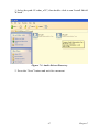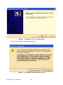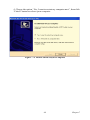
1
ARK-5280
Fanless, PC Board Expandable,
Embedded Box Computer
User Manual
Copyright
The documentation and the software included with this product are copyrighted 2006 by Advantech Co., Ltd. All rights are reserved. Advantech
Co., Ltd. reserves the right to make improvements in the products
described in this manual at any time without notice. No part of this manual may be reproduced, copied, translated or transmitted in any form or
by any means without the prior written permission of Advantech Co., Ltd.
Information provided in this manual is intended to be accurate and reliable. However, Advantech Co., Ltd. assumes no responsibility for its use,
nor for any infringements of the rights of third parties, which may result
from its use.
Acknowledgements
Award is a trademark of Award Software International, Inc.
IBM, PC/AT, PS/2 and VGA are trademarks of International Business
Machines Corporation.
Intel and Pentium are trademarks of Intel Corporation.
Microsoft Windows and MS-DOS are registered trademarks of Microsoft
Corp.
RTL is a trademark of Realtek Semi-Conductor Co., Ltd.
All other product names or trademarks are properties of their respective
owners.
For more information on this and other Advantech products, please visit
our websites at: http://www.advantech.com
For technical support and service, please visit our support website at:
http://support.advantech.com
This manual is for the ARK-5280-100A1 and ARK-5280-200A1.
Part No. 2006528010
1st Edition
Printed in Taiwan
May 2006
ARK-5280 User Manual
ii
Product Warranty (1 year)
Advantech warrants to you, the original purchaser, that each of its products will be free from defects in materials and workmanship for one year
from the date of purchase.
This warranty does not apply to any products which have been repaired or
altered by persons other than repair personnel authorized by Advantech,
or which have been subject to misuse, abuse, accident or improper installation. Advantech assumes no liability under the terms of this warranty as
a consequence of such events.
Because of Advantech’s high quality-control standards and rigorous testing, most of our customers never need to use our repair service. If an
Advantech product is defective, it will be repaired or replaced at no
charge during the warranty period. For out-of-warranty repairs, you will
be billed according to the cost of replacement materials, service time and
freight. Please consult your dealer for more details.
If you think you have a defective product, follow these steps:
1.
Collect all the information about the problem encountered. (For
example, CPU speed, Advantech products used, other hardware
and software used, etc.) Note anything abnormal and list any
onscreen messages you get when the problem occurs.
2.
Call your dealer and describe the problem. Please have your manual, product, and any helpful information readily available.
3.
If your product is diagnosed as defective, obtain an RMA (return
merchandize authorization) number from your dealer. This allows
us to process your return more quickly.
4.
Carefully pack the defective product, a fully-completed Repair and
Replacement Order Card and a photocopy proof of purchase date
(such as your sales receipt) in a shippable container. A product
returned without proof of the purchase date is not eligible for warranty service.
5.
Write the RMA number visibly on the outside of the package and
ship it prepaid to your dealer.
iii
Declaration of Conformity
CE
This product has passed the CE test for environmental specifications
when shielded cables are used for external wiring. We recommend the use
of shielded cables. This kind of cable is available from Advantech. Please
contact your local supplier for ordering information. Test conditions for
passing included the equipment being operated within an industrial enclosure. In order to protect the product from being damaged by ESD (Electrostatic Discharge) and EMI leakage, we strongly recommend the use of
CE-compliant industrial enclosure products.
FCC Class A
Note: This equipment has been tested and found to comply with the limits
for a Class A digital device, pursuant to part 15 of the FCC Rules. These
limits are designed to provide reasonable protection against harmful
interference when the equipment is operated in a commercial environment. This equipment generates, uses, and can radiate radio frequency
energy and, if not installed and used in accordance with the instruction
manual, may cause harmful interference to radio communications. Operation of this equipment in a residential area is likely to cause harmful interference in which case the user will be required to correct the interference
at his own expense.
Technical Support and Assistance
Step 1. Visit the Advantech web site at www.advantech.com/support
where you can find the latest information about the product.
Step 2. Contact your distributor, sales representative, or Advantech's customer service center for technical support if you need additional
assistance. Please have the following information ready before
you call:
- Product name and serial number
- Description of your peripheral attachments
- Description of your software (operating system, version, application software, etc.)
- A complete description of the problem
- The exact wording of any error messages
ARK-5280 User Manual
iv
ARK-5280 Series Model
There are two sub-models in ARK-5280 series as listed below:
ARK-5280-1S3A1 LV Celeron M 1.3 GHz Embedded Box Computer,
with VGA, Fast Ethernet, PS/2 (K/B & Mouse), 3 x RS-232, 1 x RS-232/
422/485, 2 x USB, DVI, Audio
ARK-5280-1S6A1 LV Pentium M 1.6GHz, Embedded Box Computer,
with VGA, Fast Ethernet, PS/2 (K/B & Mouse), 3 x RS-232, 1 x RS-232/
422/485, 2 x USB, DVI, Audio
Packing List
Before setting up the system, check that the items listed below are
included and in good condition. If any item does not accord with the
table, please contact your dealer immediately.
• 1 x ARK-5280 Unit
• 1 x PS2 Keyboard/Mouse Cable (P/N: 1700060202)
• 1 x Advantech library CD (P/N:2066000001)
• 1 x Utility CD (P/N:2066528000)
• 1 x Rear Mounting Bracket (P/N: 1960004453)
• 2 x Bottom Mounting Brackets (P/N: 1960004454)
• 1 x Power Cable, DIN-Jack to DC-Plug (P/N: 1700001861)
Note:
1 of 2 Bottom mounting brackets is made for
common usage for both table and wall mount
v
Safety Instructions
1.
Read these safety instructions carefully.
2.
Keep this User's Manual for later reference.
3.
Disconnect this equipment from any AC outlet before cleaning.
Use a damp cloth. Do not use liquid or spray detergents for cleaning.
4.
For plug-in equipment, the power outlet socket must be located
near the equipment and must be easily accessible.
5.
Keep this equipment away from humidity.
6.
Put this equipment on a reliable surface during installation. Dropping it or letting it fall may cause damage.
7.
The openings on the enclosure are for air convection. Protect the
equipment from overheating. DO NOT COVER THE OPENINGS.
8.
Make sure the voltage of the power source is correct before connecting the equipment to the power outlet.
9.
Position the power cord so that people cannot step on it. Do not
place anything over the power cord.
10.
All cautions and warnings on the equipment should be noted.
11.
If the equipment is not used for a long time, disconnect it from the
power source to avoid damage by transient overvoltage.
12.
Never pour any liquid into an opening. This may cause fire or electrical shock.
13.
Never open the equipment. For safety reasons, the equipment
should be opened only by qualified service personnel.
14.
If one of the following situations arises, get the equipment checked
by service personnel:
a. The power cord or plug is damaged.
b. Liquid has penetrated into the equipment.
c. The equipment has been exposed to moisture.
d. The equipment does not work well, or you cannot get it to work
according to the user's manual.
e. The equipment has been dropped and damaged.
f. The equipment has obvious signs of breakage.
15.
DO NOT LEAVE THIS EQUIPMENT IN AN ENVIRONMENT
WHERE THE STORAGE TEMPERATURE MAY GO BELOW -
ARK-5280 User Manual
vi
20° C (-4° F) OR ABOVE 60° C (140° F). THIS COULD DAMAGE THE EQUIPMENT. THE EQUIPMENT SHOULD BE IN A
CONTROLLED ENVIRONMENT.
16.
CAUTION: DANGER OF EXPLOSION IF BATTERY IS
INCORRECTLY REPLACED. REPLACE ONLY WITH THE
SAME OR EQUIVALENT TYPE RECOMMENDED BY THE
MANUFACTURER, DISCARD USED BATTERIES ACCORDING TO THE MANUFACTURER'S INSTRUCTIONS.
The sound pressure level at the operator's position according to IEC 7041:1982 is no more than 70 dB (A).
DISCLAIMER: This set of instructions is given according to IEC 704-1.
Advantech disclaims all responsibility for the accuracy of any statements
contained herein.
CAUTION! THIS COMPUTER IS PROVIDED WITH A BATTERY-POWERED REAL-TIME CLOCK CIRCUIT.
THERE IS A DANGER OF EXPLOSION IF
BATTERY IS INCORRECTLY REPLACED.
REPLACE ONLY WITH SAME OR EQUIVLENT
TYPE RECOMMENDED BY THE
MANUFACTURER. DISCARD USED BATTERIES
ACCORDING TO THE MANUFACTURER’S
INSTRUCTIONS.
vii
Wichtige Sicherheishinweise
1.
Bitte lesen sie Sich diese Hinweise sorgfältig durch.
2.
Heben Sie diese Anleitung für den späteren Gebrauch auf.
3.
Vor jedem Reinigen ist das Gerät vom Stromnetz zu trennen. Verwenden Sie Keine Flüssig-oder Aerosolreiniger. Am besten dient ein
angefeuchtetes Tuch zur Reinigung.
4.
Die NetzanschluBsteckdose soll nahe dem Gerät angebracht und
leicht zugänglich sein.
5.
Das Gerät ist vor Feuchtigkeit zu schützen.
6.
Bei der Aufstellung des Gerätes ist auf sicheren Stand zu achten.
Ein Kippen oder Fallen könnte Verletzungen hervorrufen.
7.
Die Belüftungsöffnungen dienen zur Luftzirkulation die das Gerät
vor überhitzung schützt. Sorgen Sie dafür, daB diese Öffnungen nicht
abgedeckt werden.
8.
Beachten Sie beim. AnschluB an das Stromnetz die AnschluBwerte.
9.
Verlegen Sie die NetzanschluBleitung so, daB niemand darüber
fallen kann. Es sollte auch nichts auf der Leitung abgestellt werden.
10. Alle Hinweise und Warnungen die sich am Geräten befinden sind
zu beachten.
11. Wird das Gerät über einen längeren Zeitraum nicht benutzt, sollten
Sie es vom Stromnetz trennen. Somit wird im Falle einer Überspannung
eine Beschädigung vermieden.
12. Durch die Lüftungsöffnungen dürfen niemals Gegenstände oder
Flüssigkeiten in das Gerät gelangen. Dies könnte einen Brand bzw. elektrischen Schlag auslösen.
13. Öffnen Sie niemals das Gerät. Das Gerät darf aus Gründen der elektrischen Sicherheit nur von authorisiertem Servicepersonal geöffnet
werden.
14. Wenn folgende Situationen auftreten ist das Gerät vom Stromnetz
zu trennen und von einer qualifizierten Servicestelle zu überprüfen:
a.
Netzkabel oder Netzstecker sind beschädigt.
b.
Flüssigkeit ist in das Gerät eingedrungen.
c.
Das Gerät war Feuchtigkeit ausgesetzt.
d.
Wenn das Gerät nicht der Bedienungsanleitung entsprechend funktioniert oder Sie mit Hilfe dieser Anleitung keine Verbesserung erzielen.
ARK-5280 User Manual
viii
e.
Das Gerät ist gefallen und/oder das Gehäuse ist beschädigt.
f.
Wenn das Gerät deutliche Anzeichen eines Defektes aufweist.
15. VOSICHT: Explisionsgefahr bei unsachgemaben Austausch der
Batterie. Ersatz nur durch densellben order einem vom Hersteller empfohlene-mahnlichen Typ. Entsorgung gebrauchter Batterien navh Angaben des Herstellers.
16. ACHTUNG: Es besteht die Explosionsgefahr, falls die Batterie auf
nicht fach-männische Weise gewechselt wird. Verfangen Sie die Batterie
nur gleicher oder entsprechender Type, wie vom Hersteller empfohlen.
Entsorgen Sie Batterien nach Anweisung des Herstell-ers.
Der arbeitsplatzbezogene Schalldruckpegel nach DIN 45 635 Teil 1000
beträgt 70dB(A) oder weiger.
Haftungsausschluss: Die Bedienungsanleitungen wurden entsprechend
der IEC-704-1 erstellt. Advantech lehnt jegliche Verantwortung für die
Richtigkeit der in diesem Zusammenhang getätigten Aussagen ab.
Safety Precaution - Static Electricity
Follow these simple precautions to protect yourself from harm and the
products from damage.
1.
To avoid electrical shock, always disconnect the power from your
PC chassis before you work on it. Don't touch any components on
the CPU card or other cards while the PC is on.
2.
Disconnect power before making any configuration changes. The
sudden rush of power as you connect a jumper or install a card may
damage sensitive electronic components.
ix
ARK-5280 User Manual
x
Contents
Chapter
1 Overview .......................................................... 2
1.1
1.2
1.3
1.4
Chapter
Introduction ....................................................................... 2
Features ............................................................................. 2
1.2.1
1.2.2
1.2.3
Fanless Power Computing Performance ........................ 2
Compact, Extremely Robust Construction .................... 2
Highly Optimized Integration ........................................ 2
Hardware Specifications ................................................... 3
1.3.1
1.3.2
1.3.3
1.3.4
1.3.5
1.3.6
1.3.7
1.3.8
1.3.9
1.3.10
Processor System ........................................................... 3
Display ........................................................................... 3
Ethernet .......................................................................... 3
Audio ............................................................................. 4
Other .............................................................................. 4
Storage ........................................................................... 4
PC Board Expansion ...................................................... 4
Mechanical ..................................................................... 4
Internal DC-to-DC Power Supply Unit ......................... 5
Environment Specifications ........................................... 5
Figure 1.1:PCI Board Power Consumption Limit ......... 6
Chassis Dimensions........................................................... 7
Figure 1.2:ARK-5280 Dimensions ................................ 7
2 Hardware Functionality ............................... 10
2.1
Introduction of External I/O Connectors......................... 10
2.2
Front Panel External I/O Connectors .............................. 10
Figure 2.1:Front Panel External I/O Connectors ......... 10
2.2.1
2.2.2
2.2.3
2.2.4
2.2.5
2.2.6
2.2.7
2.2.8
2.2.9
Power ON/OFF Button ................................................ 10
LED Indicators ............................................................. 10
Power Input Connector ................................................ 11
Figure 2.2:4-pole, DC DIN-Jack .................................. 11
Table 2.1:Power Connector Pin Assignments ............. 11
COM2 Connector ......................................................... 11
Figure 2.3:COM 2 Connector ...................................... 11
Table 2.2:COM1 Serial Port Pin Assignments ............ 11
COM1, COM3, and COM4 Connector ........................ 12
Figure 2.4:COM1, COM3 and COM 4 Connector ...... 12
Table 2.3:COM2~4 Serial Port Pin Assignments ........ 12
Audio Connector .......................................................... 13
DVI Connector ............................................................. 13
Figure 2.5:DVI Connector ........................................... 13
Table 2.4:DVI Port Pin Assignments .......................... 13
Ethernet Connector (LAN) .......................................... 14
Figure 2.6:RJ-45 Connector ......................................... 14
Table 2.5:RJ-45 Connector pin assignments ............... 14
PS2 Keyboard/Mouse Connector ................................ 15
xi
Table of Contents
Figure 2.7:PS/2 Mouse Connector ............................... 15
Table 2.6:PS2 Keyboard and PS2 Mouse Connector .. 15
2.2.10 VGA Connector ........................................................... 16
Figure 2.8:VGA Connector .......................................... 16
Table 2.7:Table 2.10: VGA port pin assignments ...... 16
2.2.11 USB Connector ............................................................ 16
Figure 2.9:USB Connector .......................................... 17
Table 2.8:USB Connector ............................................ 17
Chapter
Chapter
3 Hardware Installation & Upgrade .............. 20
3.1
3.2
3.3
Jumpers and Connectors.................................................. 20
Setting Jumpers ............................................................... 20
Jumper Location.............................................................. 21
3.4
COM2 RS-232/422/485 Jumper setting (JP1) ................ 22
3.5
CMOS Clearance (JP2) ................................................... 22
3.6
PCl Card Power Selection ............................................... 23
3.7
3.8
Connecting Power .......................................................... 23
Installing the DDR SDRAM Memory Module ............... 23
3.9
Install a Compact Flash Card .......................................... 25
3.10
Installing the 2.5" Hard Disk Drive (HDD) ................... 26
3.11
Installing the PCI card..................................................... 28
Table 3.1:Jumpers ........................................................ 21
Figure 3.1:Jumper Location of Internal SBC Board .... 21
Table 3.2:COM2 RS-232/422/485 Jumper Selection .. 22
Table 3.3:Clear CMOS Jumper (JP3) .......................... 22
Table 3.4:PCl Card Power Selection ........................... 23
Figure 3.2:Disconnect the Power Cord ........................ 23
Figure 3.3:Unscrew the Top Cover Screws ................. 24
Figure 3.4:Remove the Top Cover and PCI Cover ...... 24
Figure 3.5:Insert the SODIMM Module ...................... 25
Figure 3.6:Install the CF Card ..................................... 26
Figure 3.7:Remove the HDD cover frame ................... 27
Figure 3.8:Connect the HDD and IDE Cable .............. 27
Figure 3.9:Install the HDD into the HDD Housing ..... 28
Figure 3.10:Remove the PCI dummy bracket ............. 29
Figure 3.11:Insert the PCI Card and Fasten ................. 30
Figure 3.12:Adjust the Depressed Rubber Height ....... 30
4 Award BIOS Setup........................................ 32
4.1
Introduction ..................................................................... 32
4.2
Entering Setup ................................................................. 32
4.3
Standard CMOS Setup .................................................... 33
4.4
Advanced BIOS Features ................................................ 34
4.1.1
CMOS RAM Auto-backup and Restore ...................... 32
Figure 4.1:Award BIOS Setup ..................................... 33
Figure 4.2:Standard CMOS Features ........................... 34
4.4.1
4.4.2
ARK-5280 User Manual
Figure 4.3:Advanced BIOS Features ........................... 35
Virus Warning .............................................................. 35
L1 & L2 Cache ............................................................ 35
xii
4.4.3
4.4.4
4.4.5
4.4.6
4.4.7
4.4.8
4.4.9
4.4.10
4.4.11
4.4.12
4.4.13
4.4.14
4.5
Advanced Chipset Features............................................. 37
4.5.1
4.5.2
4.5.3
4.5.4
4.5.5
4.5.6
4.5.7
4.5.8
4.5.9
4.5.10
4.5.11
4.5.12
4.5.13
4.5.14
4.5.15
4.5.16
4.5.17
4.5.18
4.6
Quick Power On Self Test ........................................... 35
First/Second/Third/Other Boot Device ........................ 35
Swap Floppy Drive ...................................................... 35
Boot UP Floppy Seek .................................................. 36
Boot Up NumLock Status ............................................ 36
Gate A20 Option .......................................................... 36
Typematic Rate Setting ................................................ 36
Typematic Rate (Chars/Sec) ........................................ 36
Typematic Delay (msec) .............................................. 36
Security Option ............................................................ 36
APIC Mode .................................................................. 37
MPS Version Control For OS ...................................... 37
Figure 4.4:Advanced Chipset Features Setup .............. 37
DRAM Timing Selectable ........................................... 37
CAS Latency Time ...................................................... 37
Active to Precharge Delay ........................................... 38
DRAM RAS# to CAS# Delay ..................................... 38
DRAM RAS# Precharge .............................................. 38
DRAM Data Integrity Mode ........................................ 38
MGM Core Frequency ................................................. 38
System BIOS Cacheable .............................................. 38
Video BIOS Cacheable ................................................ 38
Memory Hole At 15M-16M ........................................ 38
Delayed Transaction .................................................... 39
Delay Prior to Thermal ................................................ 39
AGP Aperture Size (MB) ............................................ 39
Figure 4.5:**ON Chip VGA Setting** Screen ........... 39
On-Chip VGA .............................................................. 39
On-Chip Frame Buffer Size ......................................... 39
Boot Display ................................................................ 40
Panel Scaling ................................................................ 40
Panel Resolution .......................................................... 40
Figure 4.6:“Boot Display” Selection ........................... 40
Figure 4.7:“Panel Number” (Resolution) Selection .... 41
Integrated Peripherals...................................................... 41
4.6.1
4.6.2
4.6.3
4.6.4
4.6.5
4.6.6
4.6.7
Figure 4.8:Integrated peripherals ................................. 41
IDE Master/Slave PIO/UDMA Mode, ......................... 42
On-Chip Primary/Secondary PCI IDE ......................... 42
Figure 4.9:On-Chip IDE Device .................................. 42
IDE HDD Block Mode ................................................ 42
Figure 4.10:Onboard Device ........................................ 43
USB Controller ............................................................ 43
USB 2.0 Controller ...................................................... 43
USB Keyboard/Mouse Support ................................... 43
AC97 Audio ................................................................. 43
xiii
Table of Contents
4.6.8
4.6.9
4.6.10
4.6.11
4.6.12
4.6.13
4.6.14
4.6.15
4.6.16
4.6.17
4.6.18
4.6.19
4.7
Power Management Setup............................................... 46
4.7.1
4.7.2
4.7.3
4.7.4
4.7.5
4.7.6
4.7.7
4.7.8
4.7.9
4.7.10
4.7.11
4.7.12
4.7.13
4.7.14
4.7.15
4.7.16
4.7.17
4.8
ACPI function .............................................................. 46
ACPI Suspend Type ..................................................... 46
Power Management ..................................................... 46
Figure 4.12:Power Management Setup ........................ 47
Video Off In Method ................................................... 47
Video Off In Suspend .................................................. 47
Suspend type ................................................................ 47
Modem Use IRQ .......................................................... 47
Suspend Mode .............................................................. 47
HDD Power Down ....................................................... 48
Soft-Off by PWR-BTTN ............................................. 48
CPU THRM-Throttling ................................................ 48
Wake-up By PCI card .................................................. 48
Power On By Ring ....................................................... 48
Resume By Alarm ........................................................ 48
Primary IDE 0 (1) and Secondary IDE 0 (1) ............... 49
FDD, COM, LPT PORT .............................................. 49
PCI PIRQ [A-D]# ........................................................ 49
PnP/PCI Configurations .................................................. 49
4.8.1
4.8.2
4.8.3
4.9
Init Display First .......................................................... 43
Figure 4.11:Super IO Device ....................................... 44
Onboard FDC Controller ............................................. 44
Onboard Serial Port ..................................................... 44
UART Mode Select ..................................................... 44
RxD, TxD Active ......................................................... 44
IR Transmission Delay ................................................ 44
UR2 Duplex Mode ....................................................... 45
Onboard Parallel Port ................................................... 45
Parallel Port Mode ....................................................... 45
EPP Mode Select ......................................................... 45
ECP Mode Use DMA .................................................. 45
PWRON After PWR-Fail ............................................ 45
Figure 4.13:PnP/PCI Configurations ........................... 49
Reset Configuration Data ............................................. 50
Resources controlled by: .............................................. 50
PCI/VGA Palette Snoop .............................................. 50
PC Health Status.............................................................. 50
4.9.1
4.9.2
4.9.3
Figure 4.14:PC Health Status ....................................... 50
CPU Warning Temperature ......................................... 51
Temperatures/Voltages ................................................ 51
Shutdown Temperature ................................................ 51
4.10
Frequency/Voltage Control ............................................. 51
4.11
4.12
Password Setting ............................................................. 52
Save & Exit Setup ........................................................... 52
Figure 4.15:Frequency/Voltage Control ..................... 51
ARK-5280 User Manual
xiv
4.13
Chapter
Chapter
5 PCI SVGA Setup ........................................... 54
5.1
Introduction ..................................................................... 54
5.2
Installation of the SVGA Driver ..................................... 54
5.3
Further information ......................................................... 58
5.1.1
5.1.2
5.1.3
5.2.1
Chipset ......................................................................... 54
Display memory ........................................................... 54
Display types ................................................................ 54
Installation for Windows 2000/XP .............................. 54
Figure 5.1:Directory of VGA Driver ........................... 55
Figure 5.2:VGA Driver Installation Setup Screen ....... 56
Figure 5.3:Intel Extreme Graphics 2 Installer ............. 56
Figure 5.4:License Agreement ..................................... 57
Figure 5.5:Installation Complete ................................. 57
6 PCI Bus Ethernet Interface.......................... 60
6.1
6.2
Chapter
Exit Without Saving ........................................................ 52
Introduction ..................................................................... 60
Installation of Ethernet driver ......................................... 60
6.2.1
Installation for Windows XP ....................................... 61
Figure 6.1:Device Manager ......................................... 61
Figure 6.2:Update Driver ............................................. 62
Figure 6.3:Hardware Update Wizard ........................... 62
Figure 6.4:Choose Automatic Installation ................... 63
Figure 6.5:Hardware Installation ................................. 63
Figure 6.6:Completing the Hardware Update Wizard . 64
7 Audio Setup.................................................... 66
7.1
7.2
Introduction ..................................................................... 66
Driver Installation ........................................................... 66
7.2.1
7.2.2
Before you begin .......................................................... 66
Windows XP driver ..................................................... 66
Figure 7.1:Audio Driver Directory .............................. 67
Figure 7.2:Realtek AC’97 Audio Setup ....................... 68
Figure 7.3:Software Installation Screen ....................... 68
Figure 7.4:Install Shield Wizard Complete ................. 69
Appendix A Watchdog Timer............................................ 72
A.1
Watchdog Programming ................................................ 72
xv
Table of Contents
ARK-5280 User Manual
xvi
CHAPTER
1
2
Overview
This chapter gives background information on the ARK-5280, including an
overview and specifications.
Sections include:
• Introduction
• Features
• Hardware Specifications
• Chassis Dimension
Chapter 1 Overview
1.1 Introduction
ARK-5280 is a powerful, robust and fanless Embedded Box Computer.
The high performance ARK-5280 is equipped with socket 479 that supports Intel Celeron-M and Pentium-M processors, which is highly suitable for embedded and industrial PC applications requiring high
processor performance within a limited space. Featuring two PCI slots for
application expansion and system integration, ARK-5280 also carries
four USB 2.0 and four serial port communication I/O interfaces. It can
support up to 2 GB DDR SDRAM of main memory and has dual independent display support from the built-in CRT/VGA and DVI interfaces
that gives ARK-5280 great flexibility within space critical environments.
ARK-5280 is ideal for embedded system applications such as machine
automation, and industrial plant and cabinet integration.
1.2 Features
1.2.1 Fanless Power Computing Performance
• Fanless operation in sealed construction utilizing low thermal emission
processors
• Supports Socket 479 type Intel Pentium M and Celeron M processors
1.2.2 Compact, Extremely Robust Construction
• Robust sealed Aluminum casting construction using a modularized
design to offer maximize space efficiency
• Rubber anti-vibration card-holder for PC expansion boards and antivibration HDD to ensure maximum reliability
1.2.3 Highly Optimized Integration
• Simple and modularized service-friendly design
• Quick installation, easy expansion and maintenance
• Systems are supplied “Ready-to-Run”
• Access wide-range of 9 ~ 32 VDC power input source with ATX support; offers flexibility for various automation environments
• Long life cycle support for product continuity to secure investment
ARK-5280 User Manual
2
1.3 Hardware Specifications
1.3.1 Processor System
Processor Support
Supports uFCPGA2, 478 pin embedded Intel Pentium M or Celeron M
processors, and supports up to Intel Pentium M processor 745 at 1.8 GHz
• Celeron M 1.3 GHz (ARK-5280-1S3A1)
• Pentium M 1.6 GHz (ARK-3380-1S6A1)
System Chipset
• Intel 855GME Graphics Memory Controller Hub (GMCH) Chipset
• Intel FW82801DB I/O Controller Hub 4 (ICH4) Chipset
• 400 MHz FSB
BIOS:
4 Mbit Flash BIOS, supports Plug & Play, APM 1.2 ACPI Supported
Second level cache
• Celeron M processor: 512 KB or 1 MB
• Pentium M processor 1 MB or 2 MB
System Memory
• Dual-200 pin SO-DIMM sockets
• Supports ECC DDR200/266/333 SDRAM Up to 2GB
1.3.2 Display
Chipset
Intel 855GME GMCH, utilizing Intel Extreme Graphics 2 technology
Display Memory
Dynamic video memory allocation up to 64 MB
Display Interface support
• CRT Interface
• DVI interface, compliant with DVI specification 1.0.
• Resolution up to 2048X1536@24bpp (75 Hz)
1.3.3 Ethernet
Ethernet Controller:
Intel 82551ER Ethernet Controller
3
Chapter 1
Ethernet Interface
Built-in Dual RJ45 ports as LAN 1 and LAN 2
1.3.4 Audio
Audio Interface
• Audio controller on the ICH4 chip.
• Realtek ACL202 AC97 Codec
• AC97 3D surround stereo sound, Dual 2.2 W Amplifier
• Supports Line_In, Speaker_Out, and Microphone_In connectors on the
front side.
1.3.5 Other
Watchdog Timer:
255 levels timer interval, setup by software
Series Port:
One RS-232/422/485 port (COM2) and 3*RS-232 port (COM1,COM3,
and COM4) on the front side.
Keyboard/Mouse:
One PS/2 Port to support PS/2 Mouse and PS/2 Keyboard
USB:
• ARK-5280 Support up to 4*USB 2.0 compliant universal series bus
ports.
• ARK-5280 default supports 2*USB 2.0 compliant universal series bus
ports.
• Additional 2*USB 2.0 compliant universal series bus ports can be supported optionally by Dual-USB Cable-Bracket (Part # 1700001934)
1.3.6 Storage
• Supports one drive bay space for 2.5’’ HDD
• Supports one Compact Flash socket for Type I/II Compact Flash
1.3.7 PC Board Expansion
• Built-in 2*PCI expansion slots
• Supports maximum length of 185 mm of PCB boards expansion
1.3.8 Mechanical
Construction: Aluminum housing
Mounting: Desktop mounting and wall mounting
ARK-5280 User Manual
4
Dimension (W x H x D): 137 x 189 x 221 mm (5.39”x 7.44”x 8.70”)
Weight: Net 5.2 KG
1.3.9 Internal DC-to-DC Power Supply Unit
Output Rating: DC 120 W
Fuse Rating: DC 15 A @ 63 V
Input Voltage: 9 VDC ~ 32.5 VDC,
• Supports Power Input over voltage protection
• Supports Maximum Power Input:
9VDC / 14 A @ 126W
12VDC / 10 A @ 120W
16VDC / 8 A @ 128W
19VDC / 6.5 A @ 124W
24VDC / 5 A @ 120W
32VDC / 3 A @ 100W
1.3.10 Environment Specifications
Operating Temperature
• System Operating Temperature when system running without PCI
expansion board
When System is equipped with Industrial Grade Compact Flash Disk
only:
-20 to 55° C (without PCI expansion board)
When System is equipped with 2.5-inch Hard Disk:
0 to 45° C (without PCI expansion board)
• System Operating Temperature when system is running with PCI
expansion board
Please carefully review the “Figure 1.1 PCI expansion board power consumption limit diagram”. It describes the limitation of the maximum
ambient temperature that ARK-5280 could support when ARK-5280 system is running with different power consumption of PCI Expansion
boards.
For example: If you have plugged the PCI Expansion boards to the ARK5280 system and it, if the total power consumption of PCI Expansion
5
Chapter 1
Boards are 20W, that means the ARK-5280 can only works under the
maximum of ambient temperature of 30°C.
Figure 1.1: PCI Board Power Consumption Limit
Relative humidity 95 % @ 40° C (non-condensing)
Vibration loading during operation
• When system is equipped with Industrial grade Compact Flash Disk:
5Grms, IEC 60068-2-64, random, 5~500Hz, 1 oct./min, 1hr/axis.
• When system is equipped with 2.5-inch hard disk:
1Grms, IEC 60068-2-64, random, 5~500Hz, 1 oct./min, 1hr/axis.
Shock during operation
• When system is equipped with Compact Flash Disk:
50G, IEC 60068-2-27, half sine, 11 ms duration
• When system is equipped with 2.5-inch Hard Disk:
20G, IEC 60068-2-27, half sine, 11 ms duration
EMC Approved: CE, FCC Class A
Safety Approved: UL
ARK-5280 User Manual
6
90.00
137.00
234.00
189.00
215.00
234.00
90.00
221.00
10.00
R2
.5
0
R5.5
0
35.50
1.4 Chassis Dimensions
7.00
Figure 1.2: ARK-5280 Dimensions
7
Chapter 1
ARK-5280 User Manual
8
CHAPTER
2
2
Hardware Functionality
This chapter shows how to set up the ARK5280’s hardware functions, including connecting peripherals, switches and indicators.
Sections include:
• Introduction of External I/O Connectors
• Front Panel External I/O Connectors
• Power Connector
• LED Indicators
• COM2 Connector
• COM1, COM3 and COM4
• Audio Connector
• DVI Connector
• Ethernet Connector
• PS2 Keyboard/Mouse Connector
• VGA Connector
• USB Connectors
Chapter 2 Hardware Functionality
2.1 Introduction of External I/O Connectors
The following two figures show the external I/O connectors on ARK5280. The following sections give you detailed information about functions of each I/O connector.
Figure 2.1: Front Panel External I/O Connectors
2.2 Front Panel External I/O Connectors
2.2.1 Power ON/OFF Button
The ARK-5280 comes with a Power On/Off button that supports the dual
function of Soft Power -On/Off (Instant off or Delay 4 Second), and
Suspend.
2.2.2 LED Indicators
There are two LEDs on the ARK-5280 front panel for indicating system
status: PWR LED is for power status and flashes in green color; HDD
ARK-5280 User Manual
10
LED is for hard disk and compact flash disk status, which flashes in red
color.
2.2.3 Power Input Connector
The ARK-5280 comes with a 4-pole DIN-jack that carries 9~35 VDC
external power input. Please refer to Table 2.1 for their pin assignments.
2
1
3
4
Figure 2.2: 4-pole, DC DIN-Jack
Table 2.1: Power Connector Pin Assignments
Pin
Signal Name
1
+9~35VDC
2
+9~35VDC
3
GND
4
GND
2.2.4 COM2 Connector
The ARK-5280 provides a D-sub 9-pin connector, which offers one RS232/422/485 serial communication interface port of COM1. The default
setting of COM2 is RS-232. Please refer to Table 2.3 for their pin assignments and jumper settings for setting up RS-422 and RS-485.
1 2 3 4 5
6 7 8 9
Figure 2.3: COM 2 Connector
Table 2.2: COM1 Serial Port Pin Assignments
Pin
RS-232
RS-422
RS-485
Signal Name
Signal Name
Signal Name
11
Chapter 2
1
DCD
Tx-
DATA-
2
RxD
Tx+
DATA+
3
TxD
Rx+
NC
4
DTR
Rx-
NC
5
GND
GND
GND
6
DSR
NC
NC
7
RTS
NC
NC
8
CTS
NC
NC
9
RI
NC
NC
Note:
NC represents “No Connection”
2.2.5 COM1, COM3, and COM4 Connector
The ARK-5280 provides three-RS-232 ports by three D-sub 9-pin connectors. Please refer to Table 2.3 for their pin assignments.
1 2 3 4 5
6 7 8 9
Figure 2.4: COM1, COM3 and COM 4 Connector
Table 2.3: COM2~4 Serial Port Pin Assignments
Pin
Signal Name
1
DCD
2
RxD
3
TxD
4
DTR
5
GND
6
DSR
7
RTS
ARK-5280 User Manual
12
8
CTS
9
RI
2.2.6 Audio Connector
The ARK-5280 offers AC97 stereo Audio output ports by three phone
jack (3.5, 5P, 90D(F) connectors of Line_In (BLUE color), Speaker_Out
(LIME color) and Mic_In (Pink color).
Line-In Connector
Footprint Phone Jack 3.5Ø 5P, 90°, Female, BLUE color, Shielded
Speaker-Out Connector
Footprint Phone Jack 3.5Ø 5P, 90°, Female, LIME color, Shielded
Mic-In Connector
Footprint Phone Jack 3.5Ø 5P, 90°, Female, PINK color, Shielded
2.2.7 DVI Connector
The ARK-5280 offers a Digital Visual Interface through a D-sub 24-pin
female connector, that supports high-speed, high-resolution digital displays. Please refer to Table 2.7 for their pin assignments.
Figure 2.5: DVI Connector
Table 2.4: DVI Port Pin Assignments
Description CONN. DVI (Digital-ONLY) 24Pin, 90D(F)
Pin
Pin Name
1
2
3
6
7
9
10
11
TMDS_C2#
TMDS_C2
GND
MDVI_CLK
MDVI_DATA
TMDS_C1#
TMDS_C1
GND
13
Chapter 2
14
15
16
17
18
19
22
23
24
C5
VCC_DVI
GND
HP_DET
TMDS_C0#
TMDS_C0
GND
GND
TMDS_CK
TMDS_CK#
GND
2.2.8 Ethernet Connector (LAN)
The ARK-5280 is equipped with an Intel 82551ER Ethernet controller
that is fully compliant with IEEE 802.3u 10/100Base-T CSMA/CD standards. The Ethernet port provides a standard RJ-45 jack connector with
LED indicators on the front side to show its Active/Link status (Green
LED) and Speed status (white LED).
1
8
Figure 2.6: RJ-45 Connector
Table 2.5: RJ-45 Connector pin assignments
Pin
10/100BaseT Signal Name
1
XMT+
2
XMT-
3
RCV+
4
NC
5
NC
ARK-5280 User Manual
14
6
RCV-
7
NC
8
NC
Note:
NC represents “No Connection”
2.2.9 PS2 Keyboard/Mouse Connector
The ARK-5280 provides a PS2 keyboard/mouse connector. A 6-pin miniDIN connector is located on the front panel of the ARK-5280. The ARK5280 comes with an adapter to convert from the 6-pin mini-DIN connector to two 6-pin mini-DIN connectors for PS2 keyboard and PS2 mouse
connection. Please refer to Table 2.9 for its pin assignments.
6
5
4
3
2
1
Figure 2.7: PS/2 Mouse Connector
Table 2.6: PS2 Keyboard and PS2 Mouse Connector
Pin
Signal Name
1
KB DATA
2
MS DATA-
3
GND
4
+5V
5
KB CLOCK
6
MS CLOCK
15
Chapter 2
2.2.10 VGA Connector
The ARK-5280 provides a high resolution VGA interface via D-sub 15pin connector to support a VGA CRT monitor. It supports VGA and
VESA, up to 1600 x 1200 @ 85-Hz resolution and up to 32 MB shared
memory.
5
1
10
6
15
11
Figure 2.8: VGA Connector
Table 2.7: Table 2.10: VGA port pin assignments
Pin
Signal Name
Pin
Signal Name
1
RED
9
NC
2
GREEN
10
GND
3
BLUE
11
NC
4
NC
12
DDC DATA
5
GND
13
H-SYNC
6
GND
14
V-SYNC
7
GND
15
DDC CLOCK
8
GND
2.2.11 USB Connector
The ARK-5280 can support up to four USB-interface connectors. By
default it provides two USB-interface connectors located on the front
metal faceplate, and an additional two USB-interface connectors can be
supported through adding the Dual-USB Cable-Bracket (Part #
1700001934). These USB-interface connectors give complete Plug &
Play and hot swap capability for up to 127 external devices. The USB
interface complies with USB UHCI, Rev. 2.0 compliant. The USB interface can be disabled in the system BIOS setup.
ARK-5280 User Manual
16
The USB-interface connector is used for connecting any device that conforms to the USB interface. Many recent digital devices conform to this
standard. The USB interface supports Plug and Play, which enables you
to connect or disconnect a device whenever you want, without turning off
the computer.
Figure 2.9: USB Connector
Table 2.8: USB Connector
Pin
Signal name
1
VCC
2
USB_P0-
3
USB_P0+
4
GND
17
Chapter 2
ARK-5280 User Manual
18
CHAPTER
3
2
Hardware Installation &
Upgrade
This chapter introduces how to initialize the ARK-5280.
Sections include:
• Jumpers and Connectors
• Connecting power
• DDR SDRAM Installation
• Compact Flash Card insertion
• 2.5” HDD installation
Chapter 3 Hardware Installation &
Upgrade
3.1 Jumpers and Connectors
The ARK-5280 Embedded Box Computer consists of an Advantech SBC
(Single Board Computer) board that is housed in an aluminum top cover,
a metal chassis with accessed bottom plate. Your CPU, HDD and
SDRAM, are all readily accessible by removing the aluminum top cover.
Any maintenance or hardware upgrades can be easily completed after
removing the top cover or the accessed bottom plate.
Warning:
Do not remove any mechanical parts, such as the
top cover, or the bottom plate until you have verified that no power is flowing within the Embedded
Box Computer. Power must be switched off and
the power cord must be unplugged.
3.2 Setting Jumpers
You can configure your ARK-5280 to match the needs of your application
by setting the jumpers. A jumper is the simplest kind of electrical switch.
It consists of two metal pins and a small metal clip (often protected by a
plastic cover) that slides over the pins to connect them. To “close” a
jumper, you connect the pins with the clip. To “open” a jumper you
remove the clip. Sometimes a jumper will have three pins, labeled 1, 2,
and 3. In this case, you would connect either pins 1 and 2 or pins 2 and 3.
The jumper settings are schematically depicted in this manual as follows:
ARK-5280 User Manual
20
A pair of needle-nose pliers may be helpful when working with jumpers.
If you have any doubts about the best hardware configuration for your
application, contact your local distributor or sales representative before
you make any changes.
3.3 Jumper Location
The ARK-5280 Embedded Box Computer has a number of jumpers
inside the chassis that allows you to configure your system to suit your
application. The table below lists the functions of the various jumpers.
Table 3.1: Jumpers
Jumper No
Function
JP1
COM2 RS232/422/485 Selection
JP2
Clear CMOS
JP4
PCI Card Power Selection
Figure 3.1: Jumper Location of Internal SBC Board
21
Chapter 3
3.4 COM2 RS-232/422/485 Jumper setting (JP1)
The COM2 port located on front metal face plate of ARK-5280 unit can
be configured to operate in RS-232, RS-422 or RS-485 mode by setting
up the Jumper Pins of JP1 located on internal motherboard.
Table 3.2: COM2 RS-232/422/485 Jumper Selection
Function
Pin Setting
RS-232 *
1-2 closed*
RS-422
3-4 closed
RS-485
5-6 closed
(*): means default setting of the jumper/function
3.5 CMOS Clearance (JP2)
This jumper is used to erase CMOS data (including the setting of date,
time and password) and reset system BIOS information.
The procedure for clearing CMOS is:
1. Turn off the system.
2. Short pin 1 and pin 2.
3. Turn on the system. The BIOS is now reset to its default setting
Table 3.3: Clear CMOS Jumper (JP3)
Function
Pin Setting
Normal *
1-2 open*
CLEAR RTC
1-2 closed
(*): means default setting of the jumper/function
Warning:
To avoid damaging the computer, always turn off
the power supply before setting Clear CMOS.
Before turning on the power supply, set the
jumper back to 3.0 V Battery On.
ARK-5280 User Manual
22
3.6 PCl Card Power Selection
Table 3.4: PCl Card Power Selection
Function
Pin Setting
+5V *
1-2 closed*
+3.3V
2-3 closed
(*): means default setting of the jumper/function
3.7 Connecting Power
Connect the ARK-5280 to a 9~32.5 VDC power source. The power source
can either be from a power adapter or an in-house power source.
3.8 Installing the DDR SDRAM Memory Module
The ARK-5280 provides two 200-pin SODIMM (Small Outline Dual
Inline Memory Module) sockets and supports 2.5V DDR SDRAM*. You
can install from 64 MB to 1 GB of DDR SDRAM memory.
The procedure for installing the DDR SDRAM SODIMM into the ARK5280 is detailed below, please follow these steps carefully.
1. Disconnect the power cord.
Figure 3.2: Disconnect the Power Cord
2. Unscrew the two screws from the top cover and remove the top cover.
23
Chapter 3
Figure 3.3: Unscrew the Top Cover Screws
3. Remove the top cover and PCI cover.
Figure 3.4: Remove the Top Cover and PCI Cover
4. Insert the SODIMM module
ARK-5280 User Manual
24
Figure 3.5: Insert the SODIMM Module
5. Reverse the steps and assemble the ARK-5280.
Note:
There are two SODIMM sockets at each side of
M/B. Here only shows the M/B bottom side
SODIMM installation. Please contact your distributor or sales representative if you want to install
the other SODIMM.
3.9 Install a Compact Flash Card
The procedure for installing a Compact Flash card into the ARK-5280 is
detailed below, please follow these steps carefully.
1. Remove the power cord. (Please see Figure 8.1)
2. Unscrew the two screws which are located on the top cover and
remove. (Please see Figure 8.2)
3. Remove the top cover and PCI cover. (Please see Figure 8.3)
25
Chapter 3
4. Install the CF card into the CF socket.
Figure 3.6: Install the CF Card
5. Reverse the steps and assemble the ARK-5280.
Note:
The CompactFlash card socket is allocated as
Secondary IDE Master.
3.10 Installing the 2.5" Hard Disk Drive (HDD)
You can attach one enhanced Integrated Device Electronics (IDE) hard
disk drive to the ARK-5280's internal controller which uses a PCI localbus interface. The advanced IDE controller supports faster data transfer
and allows the IDE hard drive to exceed 528 MB. The following are
instructions for installation:
1. Remove the power cord.
2. Unscrew the two screws from the top cover and remove.
ARK-5280 User Manual
26
3. Remove the top cover and PCI cover.
4. Unscrew the HDD cover frame screws and remove the cover frame.
Figure 3.7: Remove the HDD cover frame
5. Connect the HDD and IDE cable
Figure 3.8: Connect the HDD and IDE Cable
27
Chapter 3
6. Install the HDD into the HDD housing.
Figure 3.9: Install the HDD into the HDD Housing
7. Reverse steps 4 ~ step 1 to assemble ARK-5280.
3.11 Installing the PCI card
The ARK-5280 provides two PCI slots for extension. The procedure of
installing the PCI extension card into the ARK-5280 is detailed below,
please follow these steps carefully.
1. Remove the power cord.
2. Unscrew the two screws from the top cover and remove the top cover.
3. Remove the top cover and PCI cover.
4. Remove the PCI dummy bracket.
ARK-5280 User Manual
28
Figure 3.10: Remove the PCI dummy bracket
5. Insert the PCI card into the PCI slot and fasten the screw.
29
Chapter 3
Figure 3.11: Insert the PCI Card and Fasten
6. Adjust the depressed rubber height to fit the PCI extension card.
Rotate the rubber to
adjust its height
Figure 3.12: Adjust the Depressed Rubber Height
7. Reverse steps 4 ~ step 1 to assemble ARK-5280.
ARK-5280 User Manual
30
CHAPTER
4
2
BIOS Setup
This chapter introduces how to setup
the BIOS of the ARK-5280.
Chapter 4 Award BIOS Setup
4.1 Introduction
Award’s BIOS ROM has a built-in setup program that allows users to
modify the basic system configuration. This information is stored in a
battery-backed memory (CMOS RAM) so that it retains the setup information when the power is turned off.
4.1.1 CMOS RAM Auto-backup and Restore
The CMOS RAM is powered by an onboard button cell battery. When
you finish BIOS setup, the data in CMOS RAM will be automatically
backed up to Flash ROM. If the system operates in harsh industrial environment and causes a soft error, BIOS will recheck the data in CMOS
RAM and automatically restore the original data in Flash ROM to CMOS
RAM for booting.
Note:
If you intend to change the CMOS setting without
restoring the previous backup, you have to click
on "DEL" within two seconds of the "CMOS
checksum error..." display screen message
appearing. Then enter the "Setup" screen to
modify the data. If the "CMOS check sum
error..." message appears again and again,
please check to see if you need to replace the
battery in your system.
4.2 Entering Setup
Turn on the computer and check for the “patch code”. If there is a number
assigned to the patch code, it means that the BIOS is supported on your
CPU. If there is no number assigned to the patch code, please contact an
Advantech applications engineer to obtain an up-to-date patch code file.
This will ensure that your CPU’s system status is valid. After ensuring
that you have a number assigned to the patch code, press <Del> to allow
you to enter the setup.
ARK-5280 User Manual
32
Figure 4.1: Award BIOS Setup
4.3 Standard CMOS Setup
Choose the “Standard CMOS Features” option from the “Initial Setup
Screen” menu, and the screen below will be displayed. This menu allows
users to configure system components such as date, time, hard disk drive,
floppy drive, display, and memory.
33
Chapter 4
Figure 4.2: Standard CMOS Features
4.4 Advanced BIOS Features
The “Advanced BIOS Features” screen appears when choosing the
“Advanced BIOS Features” item from the “Initial Setup Screen” menu. It
allows the user to configure the ARK-5280 according to their particular
requirements. Below are some major items that are provided in the
Advanced BIOS Features screen. A quick booting function is provided
for your convenience. Simply enable the Quick Booting item to save
yourself valuable time
ARK-5280 User Manual
34
Figure 4.3: Advanced BIOS Features
4.4.1 Virus Warning
If enabled, a warning message and alarm beep activates if someone
attempts to write here. The commands are “Enabled” or “Disabled.”
4.4.2 L1 & L2 Cache
Enabling this feature speeds up memory access. The commands are
“Enabled” or “Disabled.”
4.4.3 Quick Power On Self Test
This option speeds up the Power-On Self Test (POST) conducted as soon
as the computer is turned on. When Enabled, BIOS shortens or skips
some of the items during the test. When Disabled, the computer conducts
normal POST procedures.
4.4.4 First/Second/Third/Other Boot Device
The BIOS tries to load the OS with the devices in the sequence selected.
Choices are: Floppy, LS/ZIP, HDD, SCSI, CDROM, LAN, Disabled.
4.4.5 Swap Floppy Drive
Logical name assignments of floppy drives can be swapped if there is
more than one floppy drive. The commands are “Enabled” or “Disabled.”
35
Chapter 4
4.4.6 Boot UP Floppy Seek
Selection of the command “Disabled” will speed the boot up. Selection
of “Enabled” searches disk drives during boot up.
4.4.7 Boot Up NumLock Status
This feature selects the “power on” state for NumLock. The commands
are “Enabled” or “Disabled.”
4.4.8 Gate A20 Option
Normal:
A pin in keyboard controller controls GateA20
Fast (Default):
Chipset controls GateA20.
4.4.9 Typematic Rate Setting
The typematic rate is the rate key strokes repeat as determined by the keyboard controller. The commands are “Enabled” or “Disabled.”
Enabling allows the typematic rate and delay to be selected.
4.4.10 Typematic Rate (Chars/Sec)
Accepts the following input values (characters/second) for typematic
rate: 6, 8, 10, 12, 15, 20, 24, 30.
4.4.11 Typematic Delay (msec)
Typematic delay is the time interval between the appearances of two consecutive characters, when holding down a key. The input values for this
category are: 250, 500, 750, 1000 (msec).
4.4.12 Security Option
This setting determines whether the system will boot up if the password is
denied. Access to Setup is always limited.
System
The system will not boot, and access to Setup will be
denied if the correct password is not entered at the
prompt.
Setup
The system will boot, but access to Setup will be
denied if the correct password is not entered at the
prompt.
Note
To disable security, select “PASSWORD SETTING”
in the main menu. At this point, you will be asked to
enter a password. Simply press <Enter> to disable
security. When security is disabled, the system will
boot, and you can enter Setup freely.
ARK-5280 User Manual
36
4.4.13 APIC Mode
This setting allows selecting an OS with greater than 64MB of
RAM.Commands are “Non-OS2” or “OS2.”
4.4.14 MPS Version Control For OS
This reports if an FDD is available for Windows 95. The commands are
“Yes” or “No.”
4.5 Advanced Chipset Features
The “Advanced Chipset Features” screen appears when choosing the
“Advanced Chipset Features” item from the “Initial Setup Screen” menu.
It allows the user to configure the system chipset according to his particular requirements. Below are some major items that are provided in the
Advanced Chipset Features screen.
Figure 4.4: Advanced Chipset Features Setup
4.5.1 DRAM Timing Selectable
This option refers to the method by which the DRAM timing is selected.
The default is By SPD.
4.5.2 CAS Latency Time
You can configure CAS latency time in HCLKs as 2 or 2.5 or 3. The system board designer should set the values in this field, depending on the
37
Chapter 4
DRAM installed. Do not change the values in this field unless you change
specifications of the installed DRAM or the installed CPU.
4.5.3 Active to Precharge Delay
The default setting for the Active to Precharge Delay is 7.
4.5.4 DRAM RAS# to CAS# Delay
This option allows you to insert a delay between the RAS (Row Address
Strobe) and CAS (Column Address Strobe) signals. This delay occurs
when the SDRAM is written to, read from or refreshed. Reducing the
delay improves the performance of the SDRAM.
4.5.5 DRAM RAS# Precharge
This option sets the number of cycles required for the RAS to accumulate
its charge before the SDRAM refreshes. The default setting for the Active
to Precharge Delay is 3.
4.5.6 DRAM Data Integrity Mode
Select ECC if your memory module supports it. The memory controller
will detect and correct single-bit soft memory errors. The memory controller will also be able to detect double-bit errors though it will not be
able to correct them. This provides increased data integrity and system
stability.
4.5.7 MGM Core Frequency
This field sets the frequency of the DRAM memory installed. The default
setting is Auto Max 266MHz.
4.5.8 System BIOS Cacheable
The setting of Enabled allows caching of the system BIOS ROM at
F000h-FFFFFh, resulting in better system performance. However, if any
program writes to this memory area, a system error may result.
4.5.9 Video BIOS Cacheable
The Setting Enabled allows caching of the video BIOS ROM at C0000hF7FFFh, resulting in better video performance. However, if any program
writes to this memory area, a system error may result.
4.5.10 Memory Hole At 15M-16M
In order to improve performance, certain space in memory can be
reserved for ISA cards. This memory must be mapped into the memory
space below 16 MB. The choices are Enabled and Disabled.
ARK-5280 User Manual
38
4.5.11 Delayed Transaction
The chipset has an embedded 32-bit posted write buffer to support delay
transactions cycles. Select Enabled to support compliance with PCI specification version 2.1.
4.5.12 Delay Prior to Thermal
This field activates the CPU thermal function after the systems boots for
the set number of minutes. The options are 16Min and 64Min.
4.5.13 AGP Aperture Size (MB)
The field sets aperture size of the graphics. The aperture is a portion of
the PCI memory address range dedicated for graphics memory address
space. Host cycles that hit the aperture range are forwarded to the AGP
without any translation. The default setting is 64M.
Figure 4.5: **ON Chip VGA Setting** Screen
4.5.14 On-Chip VGA
The default setting is Enabled.
4.5.15 On-Chip Frame Buffer Size
The default setting is 32MB. The options available include 1MB, 4MB,
8MB and 16MB.
39
Chapter 4
4.5.16 Boot Display
The default setting is VBIOS Default. The options available include
CRT, LVDS, DVI and TV.
4.5.17 Panel Scaling
The default setting is Auto. The options available include On and Off.
4.5.18 Panel Resolution
These fields allow you to select the LCD Panel type. The default values
for these ports are:
• 640 x 480
• 800 x 600
• 1024 x 768
• 1280 x 1024
• 1600 x 1200
Figure 4.6: “Boot Display” Selection
ARK-5280 User Manual
40
Figure 4.7: “Panel Number” (Resolution) Selection
4.6 Integrated Peripherals
This section sets configurations for your hard disk and other integrated
peripherals. The first screen shows three main items for user to select.
Once an item selected, a submenu appears. Details follow.
Figure 4.8: Integrated peripherals
41
Chapter 4
4.6.1 IDE Master/Slave PIO/UDMA Mode,
IDE Primary (Secondary) Master/Slave PIO/UDMA Mode (Auto) Each
channel (Primary and Secondary) has both a master and a slave, making
four IDE devices possible. Because each IDE device may have a different
Mode timing (0, 1, 2, 3, 4), it is necessary for these to be independent.
The default setting “Auto” will allow auto detection to ensure optimal
performance.
4.6.2 On-Chip Primary/Secondary PCI IDE
If you enable IDE HDD Block Mode, the enhanced IDE driver will be
enabled. Leave IDE HDD Block Mode on the default setting.
Figure 4.9: On-Chip IDE Device
4.6.3 IDE HDD Block Mode
You can enable the Primary IDE channel and/or the Secondary IDE channel. Any channel not enabled is disabled. This field is for systems with
only SCSI drives.
ARK-5280 User Manual
42
Figure 4.10: Onboard Device
4.6.4 USB Controller
Select Enabled if your system contains a Universal Serial Bus (USB) controller and you have USB peripherals. The choices: Enabled, Disabled.
4.6.5 USB 2.0 Controller
The options for this field are Enabled and Disabled. By default, this field
is set to Enabled. In order to use USB 2.0, necessary OS drivers must be
installed first. Please update your system to Windows 2000 SP4 or Windows XP SP1.
4.6.6 USB Keyboard/Mouse Support
Select Enabled if user plan to use an USB keyboard. The choice: Enabled,
Disable.
4.6.7 AC97 Audio
Select Disable if you do not want to use AC-97 audio. Option is Auto,
Disable.
4.6.8 Init Display First
This item allows you to choose which one to activate first, PCI Slot or on
chip VGA. The choices: PCI Slot, Onboard.
43
Chapter 4
Figure 4.11: Super IO Device
4.6.9 Onboard FDC Controller
When enabled, this field allows you to connect your floppy disk drives to
the onboard floppy disk drive connector instead of a separate controller
card. If you want to use a different controller card to connect the floppy
disk drives, set this field to Disabled.
4.6.10 Onboard Serial Port
These fields allow you to select the IRQ of onboard serial port with their
addresses, or you can select Disabled. The default values for these ports
are:
Serial Port 1 3F8/IRQ4
Serial Port 2 2F8/IRQ3
4.6.11 UART Mode Select
This item allows you to select UART mode. The choices: IrDA, ASKIR,
Normal.
4.6.12 RxD, TxD Active
This item allows you to determine the active of RxD, TxD. The Choices:
“Hi, Hi,” “Lo, Lo,” “Lo, Hi,” “Hi, Lo.”
4.6.13 IR Transmission Delay
This item allows you to enable/disable IR transmission delay. The
choices: Enabled, Disabled.
ARK-5280 User Manual
44
4.6.14 UR2 Duplex Mode
This item allows you to select the IR half/full duplex function. The
choices: Half, Full.
4.6.15 Onboard Parallel Port
This field sets the address of the on-board parallel port connector. These
fields allow you to select the IRQ of onboard serial port with their
addresses, or you can select Disabled. The default values for parallel
ports are: 378/IRQ7
4.6.16 Parallel Port Mode
This field allows you to set the operation mode of the parallel port. The
setting “SPP” allows standard printer port device running at normal speed
operation, but in one direction only. “EPP” allows bidirectional parallel
port operation at maximum speed. “ECP” allows the parallel port to operate in bi-directional mode and at a speed faster than the maximum data
transfer rate. “ECP + EPP” allows normal speed operation in a two-way
mode. The default value of Parallel Port Mode is “SPP”.
4.6.17 EPP Mode Select
This field allows you to select EPP port type 1.7 or 1.9. The choices:
EPP1.7, 1.9. The default value is 1.7.
4.6.18 ECP Mode Use DMA
This selection is available only if you select “ECP” or “ECP + EPP” in
the Parallel Port Mode field. In ECP Mode Use DMA, you can select
DMA channel 1, DMA channel 3, or Disable. Leave this field on the
default setting of 3.
4.6.19 PWRON After PWR-Fail
This selection is allowed you to choose 3 options of “Off”, “On” or
Former-Sts” for Power setting when abnormal electricity break occurs.
Off
When power returns after an AC power failure, the
system’s power is off. You must press the Power
button to power-on the system.
On
When power returns after an AC power failure, the
system will automatically power-on.
45
Chapter 4
Former-Sts
When power returns after an AC power failure, the
system will return to the state where you left off
before power failure occurs. If the system’s power
is off when AC power failure occurs, it will remain
off when power returns. If the system’s power is on
when AC power failure occurs, the system will
power on when power returns.
4.7 Power Management Setup
The Power Management Setup allows you to configure your system to
most effectively to save energy.
4.7.1 ACPI function
The choice: Enabled, Disabled
4.7.2 ACPI Suspend Type
This field is used to select the type of Suspend mode:
“S1 (POS)” : Enables the Power On Suspend function.
“S3 (STR)” : Enables the Suspend to RAM function.
4.7.3 Power Management
This category allows you to select the type (or degree) of power saving
and is directly related to the following modes of:
1. HDD Power Down
2. Suspend Mode
There are four selections for Power Management, three of which have
fixed mode settings:
Min. Power
Saving
Minimum power management., Suspend Mod e= 1
hr., and HDD Power Down = 15 min.
Max. Power
Saving
Maximum power management., Suspend Mode = 1
min., and HDD Power Down = 1 min.
User Defined
(Default)
Allows you to set each mode individually. When not
disabled, each of the ranges are from 1 min. to 1 hr.
except for HDD Power Down which ranges from 1
min. to 15 min. and disable.
ARK-5280 User Manual
46
Figure 4.12: Power Management Setup
4.7.4 Video Off In Method
This determines the manner in which the monitor is blanked.
V/H SYNC + Blank This will cause the system to turn off the vertical
and horizontal synchronization ports and write
blanks to the video buffer.
Blank Screen
This only writes blanks to the video buffer.
DPMS Support
Initializes display power management signaling.
Select this if your video board supports it.
4.7.5 Video Off In Suspend
When system is in suspend, video will turn off.
4.7.6 Suspend type
The options are Stop Grant and PwrOn Suspend.
4.7.7 Modem Use IRQ
This determines the IRQ in which the MODEM can use. The choices: 3,
4, 5, 7, 9, 10, 11, NA.
4.7.8 Suspend Mode
When the system enters the Suspend mode, the CPU and onboard peripherals will be shut off.
47
Chapter 4
4.7.9 HDD Power Down
You can choose to turn the HDD off after one of the time intervals listed,
or when the system is in “suspend” mode. If the HDD is in a power saving mode, any access to it will wake it up.
4.7.10 Soft-Off by PWR-BTTN
If you choose “Instant-Off”, then pushing the ATX soft power switch button once will switch the system to “system off” power mode. You can
choose “Delay 4 sec.” If you do, then pushing the button for more than 4
seconds will turn off the system, whereas pushing the button momentarily
(for less than 4 seconds) will switch the system to “suspend” mode.
4.7.11 CPU THRM-Throttling
This field allows you to select the CPU THRM-Throttling rate. The
choices: 12.5%, 25.0%, 37.5%, 50.0%, 62.5%, 75.0%, 87.5%.
4.7.12 Wake-up By PCI card
This item allows you to wake up the system via LAN from the remote
host. The choices: Enabled, Disabled.
4.7.13 Power On By Ring
Set this field to Enabled to use the modem ring-on function. This will
allow your system to power-on to respond to calls coming from an external modem.
4.7.14 Resume By Alarm
When Enabled, your can set the date and time at which the RTC (real time
clock) alarm awakens the system from Suspend mode. The choices:
Enabled, Disabled.
Enabled
When Enabled, you can set the date and time you
would like the Soft Power Down (Soft-Off) PC to
power-on in the “Date (of Month) Alarm” and “Time
(hh:mm:ss) Alarm” fields. However, if the system is
being accessed by incoming calls or the network
(Resume On
Ring/LAN) prior to the date and time set in these
fields, the system will give priority to the incoming
calls or network.
Disabled Disables the automatic power-on function. (default)
ARK-5280 User Manual
48
4.7.15 Primary IDE 0 (1) and Secondary IDE 0 (1)
When Enabled, the system will resume from suspend mode if Primary
IDE 0 (1) or Secondary IDE 0 (1) is active. The choice: Enabled, Disabled.
4.7.16 FDD, COM, LPT PORT
When Enabled, the system will resume from suspend mode if FDD, COM
port, or LPT port is active. The choice: Enabled, Disabled.
4.7.17 PCI PIRQ [A-D]#
When Enabled, the system will resume from suspend mode if interrupt
occurs. The choice: Enabled, Disabled.
4.8 PnP/PCI Configurations
This section shows how to configure the PCI bus system. It covers some
very technical items and it is strongly recommended that only experienced users should make any changes to the default settings.
Figure 4.13: PnP/PCI Configurations
49
Chapter 4
4.8.1 Reset Configuration Data
Default is Disable. Select Enable to reset Extended System Configuration
Data (ESCD) if you have installed a new add-on and system e configuration has caused such a conflict that OS cannot boot.
4.8.2 Resources controlled by:
The commands here are “Auto” or “Manual.” Choosing “manual”
requires you to choose resources from each following sub-menu. “Auto”
automatically configures all of the boot and Plug and Play devices but
you must be using Windows 95 or above.
4.8.3 PCI/VGA Palette Snoop
This is left at “Disabled.”
4.9 PC Health Status
This section shows the parameters in determining the PC Health Status.
These parameters include temperatures, fan speeds and voltages.
Figure 4.14: PC Health Status
ARK-5280 User Manual
50
4.9.1 CPU Warning Temperature
This field allows the user to set the temperature so that when the temperature is reached, the system sounds a warning. This function can help prevent damage to the system that is caused by overheating.
4.9.2 Temperatures/Voltages
These fields are the parameters of the hardware monitoring function feature of the motherboard. The values are read-only values as monitored by
the system and show the PC health status.
4.9.3 Shutdown Temperature
This field allows the user to set the temperature by which the system
automatically shuts down once the threshold temperature is reached. This
function can help prevent damage to the system that is caused by overheating.
4.10 Frequency/Voltage Control
By choosing the Frequency/Voltage Control option from the Initial Setup
Screen menu, the screen below is displayed. This sample screen contains
the manufacturer’s default values for the ARK-5280.
Figure 4.15: Frequency/Voltage Control
51
Chapter 4
4.11 Password Setting
To change the password:
1. Choose the “Set Password” option from the “Initial Setup Screen”
menu and press <Enter>.The screen will display the following message:
Please Enter Your Password
Press <Enter>
2. If the CMOS is good or if this option has been used to change the
default password, the user is asked for the password stored in the CMOS.
The screen will display the following message:
Please Confirm Your Password
Enter the current password and press <Enter>.
3. After pressing <Enter> (ROM password) or the current password
(user-defined), you can change the password stored in the CMOS. The
password must be no longer than eight (8) characters. Remember, to
enable the password setting feature, you must first select either “Setup” or
“System” from the “Advanced BIOS Features” menu.
4.12 Save & Exit Setup
If you select this and press <Enter>, the values entered in the setup utilities will be recorded in the CMOS memory of the chipset. The microprocessor will check this every time you turn your system on and compare
this to what it finds as it checks the system. This record is required for the
system to operate.
4.13 Exit Without Saving
Selecting this option and pressing <Enter> lets you exit the setup program
without recording any new values or changing old ones.
ARK-5280 User Manual
52
CHAPTER
5
2
PCI-SVGA Setup
Sections include:
• Introduction
• Installation of SVGA drivers-for
Windows 2000/XP
• Further information
Chapter 5 PCI SVGA Setup
5.1 Introduction
The board has an onboard interface. The specifications and features are
described as follows:
5.1.1 Chipset
The ARK-5280 uses a Intel 855GME + 6300ESB chipset for its graphic
controller. It supports LVDS LCD displays, conventional CRT monitors.
5.1.2 Display memory
The 855GME chip with optimized Shared Memory Architecture, supports up to 64 MB frame buffer using system memory to provide LVDS
mode up to 1280 x 1024 @ 48bpp with frequency range from 25-MHz to
112-MHz. the interface can drive CRT displays with resolutions up to
2048 x 1536 @ 24 bpp 75 Hz.
5.1.3 Display types
CRT and panel displays can be used simultaneously. The board can be set
in one of three configurations: on a CRT, on a flat panel display, or on
both simultaneously. The system is initially set to simultaneous display
mode. If you want to enable the CRT display only or the flat panel display
only, please contact Intel Corporation LTD., or our sales representative
for detailed information.
Note:
Due to Intel not supporting Win98 and Windows
ME drivers, it is not recommended to install
Win98 or Windows ME on ARK-5280 .
5.2 Installation of the SVGA Driver
Complete the following steps to install the SVGA driver. Follow the procedures in the flow chart that apply to the operating system that you are
using within your board.
5.2.1 Installation for Windows 2000/XP
To install SVGA driver for Window 2000/XP, please run the setup wizard
“Intel Extreme Graphic 2” from the CD-ROM. Example of installation is
shown bellow:
ARK-5280 User Manual
54
1. Select the path: D:\2_VGA, then double click “win2k_xp141” to run
“Install Shield Wizard”
Figure 5.1: Directory of VGA Driver
Note:
1. The windows illustrations in this chapter are
intended as examples only. Please follow the
listed steps, and pay attention to the instructions
which appear on your screen.
2. For convenience, the CD-ROM drive is designated as “D” throughout this chapter.
2. Press the “Next” button.
55
Chapter 5
Figure 5.2: VGA Driver Installation Setup Screen
3.
Press the “Next” button.
Figure 5.3: Intel Extreme Graphics 2 Installer
ARK-5280 User Manual
56
4.
In order to continue setup, you must accept the agreement.
Figure 5.4: License Agreement
5. Choose the option “Yes, I want to restart my computer now.”
Figure 5.5: Installation Complete
57
Chapter 5
5.3 Further information
For further information about the AGP/VGA installation in your ARK5280, including driver updates, troubleshooting guides and FAQ lists,
visit the following web resources:
Intel website: www.intel.com
Advantech websites: www.advantech.com, or www.advantech.com.tw
ARK-5280 User Manual
58
CHAPTER
6
2
PCI Bus
Ethernet Interface
The chapter provides information on
Ethernet configuration.
Sections include:
• Introduction
• Installation of Ethernet Drivers for
Windows XP
Chapter 6 PCI Bus Ethernet Interface
6.1 Introduction
The board is equipped with a high performance 32-bit Ethernet chipset
which is fully compliant with 802.3u 100BASE-T or 802.3z/ab
1000BASE-T. It is supported by major network operating systems. It is
also both 100Base-T and 10Base-T compatible. The Ethernet port provides a standard RJ-45 jack. The network boot feature can be utilized by
incorporating the boot ROM image files for the appropriate network
operating system. The boot ROM BIOS files are combined with system
BIOS, which can be enabled/disabled in the BIOS setup.
6.2 Installation of Ethernet driver
Before installing the Ethernet driver, note the procedures below. You
must know which operating system you are using in your board series,
and then refer to the corresponding installation flow chart. Then just follow the steps described in the flow chart. You will quickly and successfully complete the installation, even if you are not familiar with instructions for MS-DOS or Windows.
Note:
The windows illustrations in this chapter are examples only. Follow the steps and pay attention to the
instructions which appear on your screen.
ARK-5280 User Manual
60
6.2.1 Installation for Windows XP
Select ”Ethernet Controller” from Device Manager.
Figure 6.1: Device Manager
Select “Update Driver”.
61
Chapter 6
Figure 6.2: Update Driver
Click the “Next” button.
Figure 6.3: Hardware Update Wizard
Click the “Next” button.
ARK-5280 User Manual
62
Figure 6.4: Choose Automatic Installation
Please choose “Continue Anyway”.
Figure 6.5: Hardware Installation
Click the “Finish” button.
63
Chapter 6
Figure 6.6: Completing the Hardware Update Wizard
ARK-5280 User Manual
64
CHAPTER
7
2
Audio Setup
Sections include:
• Introduction
• Installation of Audio drivers for
Windows XP
Chapter 7 Audio Setup
7.1 Introduction
The ARK-5280’s audio interface provides high-quality stereo sound and
FM music synthesis (ESFM) by using the Intel ICH4 audio controller.
The audio interface can record, compress, and play back voice, sound,
and music with built-in mixer control.
7.2 Driver Installation
7.2.1 Before you begin
Please read the instructions in this chapter carefully before you attempt
installation. The audio drivers for the ARK-5280 board are located on the
audio driver CD. Run the supplied setup program to install the drivers;
don’t copy the files manually.
Note:
The files on the software installation diskette are
compressed. Do not attempt to install the drivers
by copying the files manually. You must use the
supplied setup program to install the drivers.
7.2.2 Windows XP driver
To install audio driver for Window XP, please run the setup wizard in CDROM. Example of installation is shown as below:
ARK-5280 User Manual
66
1. Select the path: D:\wdm_a357, then double click to run “Install Shield
Wizard”.
Figure 7.1: Audio Driver Directory
2. Press the “Next” button and wait for a moment.
67
Chapter 7
Figure 7.2: Realtek AC’97 Audio Setup
3. Choose the option “Continue Anyway”.
Figure 7.3: Software Installation Screen
ARK-5280 User Manual
68
4. Choose the option “Yes, I want to restart my computer now”, then click
“Finish” button to reboot your computer.
Figure 7.4: Install Shield Wizard Complete
69
Chapter 7
ARK-5280 User Manual
70
A
APPENDIX
2
Watchdog Timer
The ARK-5280 is equipped with a
watchdog timer that resets the CPU if
processing comes to a standstill for any
reason. This feature ensures system
reliability in industrial standalone or
unmanned environments.
Appendix A Watchdog Timer
A.1 Watchdog Programming
The ARK-5280 Embedded Box Computer is equipped with a watchdog
timer that resets the CPU if processing comes to a standstill for any reason. This feature ensures system reliability in industrial standalone or
unmanned environments. Below is the programming sample of Watchdog.
Watchdog: (Index Port:300H , Data Port:301)
1, Enable Watchdog
Outportb (0x2e,0x87);
Outportb (0x2e,0x87); //Entry Configuration Mode
Outportb (0x2e,0x07); //Select Register Index 0x07
Outportb (0x2f,0x08); //Select LDN 8
Outportb (0x2e,0x30); //Select LDN 8 Register Index 0x30
Outportb (0x2f,0x01); //Enable Watchdog Timer Device
Outportb (0x2e,0xaa); //Exit Configuration Mode
2, Set Watchdog Timer to 20 Second
Outportb (0x2e,0x87);
Outportb (0x2e,0x87); //Entry Configuration Mode
Outportb (0x2e,0x07); //Select Register Index 0x07
Outportb (0x2f,0x08); //Select LDN 8
Outportb (0x2e,0xf6); //Select LDN 8 Register Index 0x30
Outportb (0x2f,0x20); //Set 20 second
Outportb (0x2e,0xaa); //Exit Configuration Mode
3, Disable Watchdog
Outportb (0x2e,0x87);
Outportb (0x2e,0x87); //Entry Configuration Mode
Outportb (0x2e,0x07); //Select Register Index 0x07
Outportb (0x2f,0x08); //Select LDN 8
Outportb (0x2e,0x30); //Select LDN 8 Register Index 0x30
Outportb (0x2f,0x00); //Disable Watchdog Timer Device
Outportb (0x2e,0xaa); //Exit Configuration Mode
ARK-5280 User Manual
72