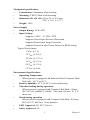
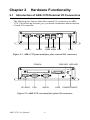
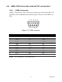
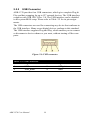
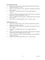
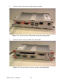
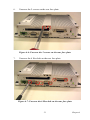
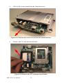
1
ARK-1370
All-In-One, Ultra compact
Embedded Box Computer
User Manual
Copyright
The documentation and the software included with this product are copyrighted 2007 by Advantech Co., Ltd. All rights are reserved. Advantech
Co., Ltd. reserves the right to make improvements in the products
described in this manual at any time without notice. No part of this manual may be reproduced, copied, translated or transmitted in any form or
by any means without the prior written permission of Advantech Co., Ltd.
Information provided in this manual is intended to be accurate and reliable. However, Advantech Co., Ltd. assumes no responsibility for its use,
nor for any infringements of the rights of third parties, which may result
from its use.
Acknowledgements
Award is a trademark of Award Software International, Inc.
IBM, PC/AT, PS/2 and VGA are trademarks of International Business
Machines Corporation.
AMD and Geode™ are trademarks of AMD Corporation.
Microsoft® Windows and MS-DOS are registered trademarks of
Microsoft Corp.
RTL is a trademark of Realtek Semi-Conductor Co., Ltd.
All other product names or trademarks are properties of their respective
owners.
For more information on this and other Advantech products, please visit
our websites at: http://www.advantech.com
http://www.advantech.com.tw/products/
Sub_Category.asp?Category_ID=1-TPYQ7&BU=ACG&PD=EC
For technical support and service, please visit our support website at:
http://support.advantech.com
This manual is for ARK-1370 series.
ARK-1370 User Manual
ii
Product Warranty (2 years)
Advantech warrants to you, the original purchaser, that each of its products will be free from defects in materials and workmanship for two years
from the date of purchase.
This warranty does not apply to any products which have been repaired or
altered by persons other than repair personnel authorized by Advantech,
or which have been subject to misuse, abuse, accident or improper installation. Advantech assumes no liability under the terms of this warranty as
a consequence of such events.
Because of Advantech’s high quality-control standards and rigorous testing, most of our customers never need to use our repair service. If an
Advantech product is defective, it will be repaired or replaced at no
charge during the warranty period. For out-of-warranty repairs, you will
be billed according to the cost of replacement materials, service time and
freight. Please consult your dealer for more details.
If you think you have a defective product, follow these steps:
1.
2.
3.
4.
5.
Collect all the information about the problem encountered. (For
example, CPU speed, Advantech products used, other hardware
and software used, etc.) Note anything abnormal and list any
onscreen messages you get when the problem occurs.
Call your dealer and describe the problem. Please have your manual, product, and any helpful information readily available.
If your product is diagnosed as defective, obtain an RMA (return
merchandise authorization) number from your dealer. This allows
us to process your return more quickly.
Carefully pack the defective product, a fully-completed Repair and
Replacement Order Card and a photocopy proof of purchase date
(such as your sales receipt) in a shippable container. A product
returned without proof of the purchase date is not eligible for warranty service.
Write the RMA number visibly on the outside of the package and
ship it prepaid to your dealer.
Part No. 2006137000
Edition 1
Printed in Taiwan
September 2007
iii
Declaration of Conformity
CE
This product has passed the CE test for environmental specifications
when shielded cables are used for external wiring. We recommend the use
of shielded cables. This kind of cable is available from Advantech. Please
contact your local supplier for ordering information.
This product has passed the CE test for environmental specifications. Test
conditions for passing included the equipment being operated within an
industrial enclosure. In order to protect the product from being damaged
by ESD (Electrostatic Discharge) and EMI leakage, we strongly recommend the use of CE-compliant industrial enclosure products.
FCC Class A
Note: This equipment has been tested and found to comply with the limits
for a Class A digital device, pursuant to part 15 of the FCC Rules. These
limits are designed to provide reasonable protection against harmful
interference when the equipment is operated in a commercial environment. This equipment generates, uses, and can radiate radio frequency
energy and, if not installed and used in accordance with the instruction
manual, may cause harmful interference to radio communications. Operation of this equipment in a residential area is likely to cause harmful interference in which case the user will be required to correct the interference
at his own expense.
ARK-1370 User Manual
iv
Technical Support and Assistance
1.
2.
Visit the Advantech web site at www.advantech.com/support
where you can find the latest information about the product.
Contact your distributor, sales representative, or Advantech's customer service center for technical support if you need additional
assistance. Please have the following information ready before you
call:
– Product name and serial number
– Description of your peripheral attachments
– Description of your software (operating system, version, application software, etc.)
– A complete description of the problem
– The exact wording of any error messages
ARK-1370 Models
Table 1.1: ARK-1370 Model list
ARK-1370F-1J0A1E:
ARK-1370F-2J0A1E:
ARK-1370F-3J0A1E:
AMD Geode™ LX800 processor 500 MHz, 2 x
Serial ports, 4 x USB 2.0, 1 x PS2, 1 x LAN, 1 x
LVDS, 1x VGA 1 x PCMCIA, AUDIO
ARK-1370F-1J0A1E with 256 MB DDR
SDRAM, 128 MB CF, pre-installed Windows CE
6.0 Professional Plus and License
ARK-1370F-1J0A1E with 512 MB DDR
SDRAM, 1 GB CF, pre-installed Windows XP
Professional Embedded FP2007 OS Image and
License
v
Packing List
•
•
•
•
•
•
•
1 x ARK-1370 Unit
1 x Driver and Utility CD for ARK-1370 series V1.10
(P/N: 2066137000)
1 x 2-P Phoenix to DC-Jack Power Cable (P/N: 1700001394)
1 x DB-9 Male to Mic_in, Ln_Out, Ln_In, Audio Cable
(P/N: 1700006011)
Optional 6P-6P-6P 20cm KB and PS/2 Mouse Y cable
(P/N: 1700060202)
Optional DIN-rail mounting accessory
(P/N: 1997001110, 1997001120, 1997001130, 1997001140)
Optional VESA mounting plate, P/N: 1960008516
If any of these items are missing or damaged, contact your distributor or
sales representative immediately.
ARK-1370 User Manual
vi
Safety Instructions
1.
2.
3.
4.
5.
6.
7.
8.
9.
10.
11.
12.
13.
14.
15.
Read these safety instructions carefully.
Keep this User Manual for later reference.
Disconnect this equipment from any AC outlet before cleaning.
Use a damp cloth. Do not use liquid or spray detergents for cleaning.
For plug-in equipment, the power outlet socket must be located
near the equipment and must be easily accessible.
Keep this equipment away from humidity.
Lay this equipment on a reliable surface when install. A drop or
fall could cause injury.
Do not leave this equipment in an uncontrolled environment; storage temperatures above 60°C may damage the equipment.
The openings on the enclosure are for air convection. Protect the
equipment from overheating. DO NOT COVER THE OPENINGS.
Make sure the voltage of the power source is correct before connecting the equipment to the power outlet.
Place the power cord such a way that people cannot step on it. Do
not place anything over the power cord. The power cord must be
rated for the product and for the voltage and current marked on the
product’s electrical ratings label. The voltage and current rating of
the cord should be greater than the voltage and current rating
marked on the product.
All cautions and warnings on the equipment should be noted.
If the equipment is not used for a long time, disconnect it from the
power source to avoid damage by transient overvoltage.
Never pour any liquid into an opening. This may cause fire or electrical shock.
Never open the equipment. For safety reasons, the equipment
should be opened only by qualified service personnel.
If one of the following situations arises, get the equipment checked
by service personnel:
– The power cord or plug is damaged.
– Liquid has penetrated into the equipment.
– The equipment has been exposed to moisture.
– The equipment does not work well, or you cannot get it to work
according to the user’s manual.
vii
16.
– The equipment has been dropped and damaged.
– The equipment has obvious signs of breakage.
CAUTION!
THIS COMPUTER IS PROVIDED WITH A BATTERY-POWERED REAL-TIME CLOCK CIRCUIT. THERE IS A DANGER
OF EXPLOSION IF BATTERY IS INCORRECTLY REPLACED.
REPLACE ONLY WITH SAME OR EQUIVLENT TYPE RECOMMENDED BY THE MANUFACTURE. DISCARD USED
BATTERIES ACCORDING TO THE MANUFACTURER°ØS
INSTRUCTIONS.
Wichtige Sicherheishinweise
1.
2.
3.
4.
5.
6.
7.
8.
9.
10.
11.
12.
Bitte lesen sie Sich diese Hinweise sorgfältig durch.
Heben Sie diese Anleitung für den späteren Gebrauch auf.
Vor jedem Reinigen ist das Gerät vom Stromnetz zu trennen. Verwenden Sie Keine Flüssig-oder Aerosolreiniger. Am besten dient
ein angefeuchtetes Tuch zur Reinigung.
Die NetzanschluBsteckdose soll nahe dem Gerät angebracht und
leicht zugänglich sein.
Das Gerät ist vor Feuchtigkeit zu schützen.
Bei der Aufstellung des Gerätes ist auf sicheren Stand zu achten.
Ein Kippen oder Fallen könnte Verletzungen hervorrufen.
Die Belüftungsöffnungen dienen zur Luftzirkulation die das Gerät
vor überhitzung schützt. Sorgen Sie dafür, daB diese Öffnungen
nicht abgedeckt werden.
Beachten Sie beim. AnschluB an das Stromnetz die AnschluBwerte.
Verlegen Sie die NetzanschluBleitung so, daB niemand darüber
fallen kann. Es sollte auch nichts auf der Leitung abgestellt werden.
Alle Hinweise und Warnungen die sich am Geräten befinden sind
zu beachten.
Wird das Gerät über einen längeren Zeitraum nicht benutzt, sollten
Sie es vom Stromnetz trennen. Somit wird im Falle einer Überspannung eine Beschädigung vermieden.
Durch die Lüftungsöffnungen dürfen niemals Gegenstände oder
Flüssigkeiten in das Gerät gelangen. Dies könnte einen Brand bzw.
elektrischen Schlag auslösen.
ARK-1370 User Manual
viii
13.
14.
15.
16.
Öffnen Sie niemals das Gerät. Das Gerät darf aus Gründen der elektrischen Sicherheit nur von authorisiertem Servicepersonal geöffnet werden.
Wenn folgende Situationen auftreten ist das Gerät vom Stromnetz
zu trennen und von einer qualifizierten Servicestelle zu überprüfen:
– Netzkabel oder Netzstecker sind beschädigt.
– Flüssigkeit ist in das Gerät eingedrungen.
– Das Gerät war Feuchtigkeit ausgesetzt.
– Wenn das Gerät nicht der Bedienungsanleitung entsprechend
funktioniert oder Sie mit Hilfe dieser Anleitung keine Verbesserung erzielen.
– Das Gerät ist gefallen und/oder das Gehäuse ist beschädigt.
– Wenn das Gerät deutliche Anzeichen eines Defektes aufweist.
VOSICHT: Explisionsgefahr bei unsachgemaben Austausch der
Batterie.Ersatz nur durch densellben order einem vom Hersteller
empfohlene-mahnlichen Typ. Entsorgung gebrauchter Batterien
navh Angaben des Herstellers.
ACHTUNG: Es besteht die Explosionsgefahr, falls die Batterie auf
nicht fach-männische Weise gewechselt wird. Verfangen Sie die
Batterie nur gleicher oder entsprechender Type, wie vom Hersteller
empfohlen. Entsorgen Sie Batterien nach Anweisung des Herstellers.
Der arbeitsplatzbezogene Schalldruckpegel nach DIN 45 635 Teil 1000
beträgt 70dB(A) oder weiger.
Haftungsausschluss: Die Bedienungsanleitungen wurden entsprechend
der IEC-704-1 erstellt. Advantech lehnt jegliche Verantwortung für die
Richtigkeit der in diesem Zusammenhang getätigten Aussagen ab.
ix
Safety Precaution - Static Electricity
Follow these simple precautions to protect yourself from harm and the
products from damage.
1.
2.
To avoid electrical shock, always disconnect the power from your
PC chassis before you work on it. Don’t touch any components on
the CPU card or other cards while the PC is on.
Disconnect power before making any configuration changes. The
sudden rush of power as you connect a jumper or install a card may
damage sensitive electronic components.
ARK-1370 User Manual
x
Contents
Chapter
1 Overview ...........................................................2
1.1
1.2
Introduction ....................................................................... 2
Features ............................................................................ 2
1.2.1
1.2.2
1.2.3
1.2.4
1.3
1.4
Ultra Compact Size, VESA Mount with Fanless Operation .................................................................................. 2
Dual Display Capability.................................................. 2
Comprehensive Communication and Connective Capacity ..................................................................................... 3
Optimized Integration in a Robust Casting Construction3
Hardware Specification ..................................................... 3
Chassis Dimensions........................................................... 6
Figure 1.1 Chassis Dimensions.................................. 6
Chapter
2 Hardware Functionality ..................................8
2.1
Introduction of ARK-1370 External I/O Connectors........ 8
Figure 2.1 ARK-1370 front metal face plate external I/
O connectors .......................................... 8
Figure 2.2 ARK-1370 rear metal face plate I/O connectors .................................................... 8
2.2
ARK-1370 front side external I/O connectors .................. 9
2.2.1
2.2.2
2.2.3
2.2.4
2.3
COM Connector.............................................................. 9
Figure 2.3 COM connector ........................................ 9
Table 2.1 COM standard serial port pin assignments.
9
USB Connector ............................................................. 10
Figure 2.4 USB connector........................................ 10
Table 2.2 USB Connector....................................... 10
PS2 Keyboard/Mouse Connector.................................. 11
Figure 2.5 PS/2 connector........................................ 11
Table 2.3 PS/2 Keyboard/Mouse connector pin assignments ............................................. 11
Ethernet Connector (LAN) ........................................... 12
Figure 2.6 Ethernet connector.................................. 12
Table 2.4 RJ-45 Connector pin assignments .......... 12
ARK-1370 rear side external I/O connectors.................. 13
2.3.1
2.3.2
2.3.3
2.3.4
2.3.5
Power ON/OFF Button ................................................. 13
LED Indicators.............................................................. 13
LVDS Connector .......................................................... 13
Figure 2.7 LVDS Connector .................................... 13
Table 2.5 LVDS Connector Pin Assignment.......... 13
PCMCIA expansion slot ............................................... 14
AUDIO Connector........................................................ 14
xi
2.3.6
2.3.7
Chapter
Figure 2.8 Audio connector ..................................... 14
Table 2.6 Audio Connector Pin Assignment .......... 14
VGA Connector ............................................................ 15
Figure 2.9 VGA connector....................................... 15
Table 2.7 VGA connector pin assignment.............. 15
Power Input Connector ................................................. 16
Figure 2.10 Power Input Connector........................... 16
Table 2.8 Power connector pin assignments........... 16
3 Hardware Installation and Upgrade ............18
3.1
3.2
3.3
Jumpers and Connectors.................................................. 18
Setting jumpers................................................................ 19
LCD Power Jumper setting (CN14) ................................ 20
Table 3.1 LCD Power Setting (CN14) ................... 20
Figure 3.1 The carrier board layout ......................... 20
3.4
3.5
3.6
Chapter
Installing the DDR SDRAM Memory Module ............... 21
Inserting the Compact Flash card.................................... 21
Connecting Power ........................................................... 21
4 Award BIOS Setup.........................................24
4.1
Introduction .................................................................... 24
4.1.1
4.2
4.2.1
4.2.2
4.2.3
4.2.4
4.2.5
4.2.6
4.2.7
4.2.8
4.2.9
4.2.10
4.2.11
4.2.12
Chapter
Main Menu.................................................................... 26
Standard CMOS Features ............................................. 27
Advanced BIOS Features.............................................. 29
Advanced Chipset Features .......................................... 31
Integrated Peripherals ................................................... 33
Power Management Setup ............................................ 35
PnP/PCI Configurations................................................ 37
PC Health Status ........................................................... 38
Load Optimized Defaults.............................................. 39
Set Password ................................................................. 40
Save & Exit Setup......................................................... 42
Quit Without Saving ..................................................... 42
5 PCI XGA/LCD Setup.....................................44
5.1
Introduction .................................................................... 44
5.1.1
5.1.2
5.1.3
Chapter
CMOS RAM Auto-backup and Restore ....................... 24
Entering Setup ................................................................. 25
CMOS setting for panel type ........................................ 44
Figure 5.1 Advanced Chipset features screen.......... 44
Display type .................................................................. 45
Dual Independent Display ............................................ 45
Figure 5.2 AMD LX800 Graphics Controller Properties - Devices........................................ 45
6 Full Disassembly Procedure ..........................48
6.1
Introduction ..................................................................... 48
ARK-1370 User Manual
xii
Figure 6.1 Unscrew the 6 screws on the bottom side...
48
Figure 6.2 Unscrew the 4 screws on the front side
frame .................................................... 49
Figure 6.3 Unscrew the 2 screws on the front face plate
49
Figure 6.4 Unscrew the 4 Hex-bolt on the front face
plate...................................................... 50
Figure 6.5 Unscrew the 4 screws on the rear side frame
50
Figure 6.6 Unscrew the 2 screws on the rear face plate
51
Figure 6.7 Unscrew the 6 Hex-bolt on the rear face
plate...................................................... 51
Figure 6.8 Pull out the carrier board from the aluminum case............................................... 52
Figure 6.9 Remove the CF card anti-shock holder .. 52
Figure 6.10 Remove the CF card ............................... 53
Figure 6.11 Turn over the carrier board and remove the
DRAM module..................................... 53
xiii
ARK-1370 User Manual
xiv
CHAPTER
1
Overview
This chapter gives background information on ARK-1370. It shows you
ARK-1370 overview and specifications.
Sections include:
•
•
•
•
•
Introduction
Hardware Specifications
Safety Precautions
ARK-1370 Series Model and
Packing List
Chassis Dimension
Chapter 1
Overview
1.1 Introduction
ARK-1370 is an ultra-compact, fanless fully sealed, robust embedded
box computer. It is designed for space critical applications that require
low power consumption. All electronics are protected in a rugged, sealed
housing that can be conveniently embedded in stand alone applications.
No external cooling is necessary. The unit features a 24-bit LVDS interface, AC’97 Audio, one LAN, four USB, two Serial communication
ports, and PC card interfaces that bring comprehensive multimedia, control and communications to meet diverse application requirements.
1.2
Features
1.2.1
•
•
•
•
1.2.2
•
Ultra Compact Size, VESA Mount with Fanless
Operation
Ultra-Compact dimensions of 189 x 41 x 136.5 mm (7.44” x 1.61”
x 5.37”)
Supports VESA mounting holes (100mm x 100 mm), which allow
direct assembly of ARK-1370 to any display device, making video
intensive applications conveniently accessible. (Optional)
Supports Desktop/Wall/Din Rail Mounting under space critical
installation conditions. (DIN-rail mounting kit is optional)
Aluminum Alloy chassis construction with high efficient fanless
performance.
Dual Display Capability
Support a wide range of video interfaces (24-bit LVDS and standard CRT interface), and AC’97 Stereo Audio. The unit is designed
for diversified applications:
– Point of Information
– Gaming
– Digital Signage
ARK-1370 User Manual
2
1.2.3
•
Comprehensive Communication and Connective Capacity
A wide range of communications interfaces (Four USB, two RS232 and Ethernet). A PC card slot enables ARK-1370 to become an
ideal solution for diversified applications, such as:
– Data communication gateway for navigation and transportation
– POS/Kiosk control, self-service of entrance control, ticketing,
payment and information preview system.
1.2.4
•
•
•
•
Optimized Integration in a Robust Casting Construction
Few Parts, Easy Integration, Easy Maintenance to reduce investment
Systems are supplied ready to run
Long life cycle support for product continuity
Wide range of DC 9 V~35 V power source offers flexibility of
power input for various automation environments.
1.3 Hardware Specification
Processor Core Logic System
•
CPU
Embedded AMD Geode™ LX800 500MHz
•
System Chipset
AMD Geode™ CS5536 companion
•
BIOS
Award 512 KB Flash BIOS
•
System Memory
– One 200 pin SO-DIMM sockets
– Support DDR SDRAM Up to 1GB
Display
•
Controller
•
Display Memory
Built-in to AMD Geode™ LX 800 processor
Optimized shared memory architecture, supports up to 64 MB
frame buffer using system memory.
3
Chapter 1
•
•
Display Interface support
– CRT Interface
– Single channel 18-bit LVDS interface
Resolution
–
CRT Mode: 1024 x 768 @ 22 bpp (85 Hz), 1600 x 1200 @
16 bpp
–
LCD/Simultaneous Mode: 1024 x 768 @ 16 bpp
Ethernet
•
•
Ethernet Controller: Intel® 82551QM Ethernet Controller
Speed: 10/100MBps, IEEE 802.3u (100 BASE-T) protocol compatible
Audio
•
Audio Interface
Built-in Audio controller on AMD Geode™ CS5536 companion
chipset AC’97 Audio stereo sound and dual output 2.2W amplifier.
USB
•
Built-in USB 2.0 controller on AMD Geode™ CS5536. Supports 4
x USB 2.0 ports
Serial Port
•
Built-in Winbond W83627HF LPC Super I/O Controller. Supports
2 x RS-232/422/485 ports by BIOS selection
PC Card
•
•
PC Card Controller: Built-in Ricon R5C485 PC Card Controller
PC Card Slot Interface: 1 x built-in PC Card that supports CardBus (Card-32) and 16-bit (PCMCIA 2.1/JEIDA4.2) cards 5V and
3.3V working power.
Others
•
•
Watchdog Timer: 255 levels timer interval, setup by software
Keyboard/Mouse: One PS/2 Port to support PS/2 Mouse and PS/2
Keyboard.
Storage
•
SSD Interface: 1 x CompactFlash socket for Type I/II CompactFlash disk
ARK-1370 User Manual
4
Mechanical specifications
•
•
•
•
Construction: Aluminum Alloy housing
Mounting: VESA*/Desk/wall mounting
Dimension (W x H x D): 189 x 41 x 136.5 mm
(7.44” x 1.61” x 5.37”)
Weight: 1 KG
Power Supply
•
•
Output Rating: 25 W, ATX
Input Voltage:
Supports 9 VDC ~ 35 VDC, ATX
Supports Power Input Reversed Protection
Supports Power Input Surge Protection
Supports Power On after Power failure via BIOS setting
Typical Power Input:
9 VDC @ 3 A,
12 VDC @ 2.4 A,
16 VDC @ 1.75 A,
19 VDC @ 1.5 A,
24 VDC @ 1.2 A,
35 VDC @ 0.8A,
Environment Specifications
•
•
•
•
•
•
Operating Temperature
– When system is equipped with Industrial Grade Compact Flash
Disk only: -40 °C to 60 °C
Relative humidity: 95 % @ 40 °C (non-condensing)
Vibration loading during operation
– When system is equipped with Compact Flash Disk: 5 Grms,
IEC 68-2-64, random, 5~500Hz, 1 Oct./min, 1hr/axis. X, Y, Z
three axes
Shock during operation
– When system is equipped with Compact Flash Disk: 50 Grms,
IEC 68-2-27, half sine, 11 ms duration.
EMC Approved: CE, FCC Class A
Safety Approved: UL
5
Chapter 1
1.4 Chassis Dimensions
VCC
GND
C N
D
I
9~
V
3 5V
Figure 1.1: Chassis Dimensions
ARK-1370 User Manual
6
CHAPTER
2
Hardware Functionality
This chapter shows how to set up ARK1370’s hardware functions, including connecting peripherals, switches and indicators.
Sections include:
•
•
•
•
•
•
•
•
Introduction of External I/O connectors
COM connectors
USB connectors
PS/2 Keyboard/Mouse connector
Ethernet connector
Power On/Off button
LED indicators
LVDS connector
Chapter 2
Hardware Functionality
2.1 Introduction of ARK-1370 External I/O Connectors
The following two figures show the external I/O connectors on ARK1370. The following sections give you detail information about function
of each I/O connector.
COM1
COM2
USB1 USB3
USB2 USB4 LAN
PS/2
Figure 2.1: ARK-1370 front metal face plate external I/O connectors
PWR LED HDD LED
PCMCIA
HDD
DC IN
9V~35V
VCC
PWR
GND
DC INPUT
VGA
AUDIO
LVDS
POWER ON/OFF
Figure 2.2: ARK-1370 rear metal face plate I/O connectors
ARK-1370 User Manual
8
2.2 ARK-1370 front side external I/O connectors
2.2.1
COM Connector
ARK-1370 provides two D-sub 9-pin connectors, which offers RS-232/
422/485 serial communication interface ports. Please see the BIOS setting.
1 2 3 4 5
6 7 8 9
Figure 2.3: COM connector
Table 2.1: COM standard serial port pin assignments
Pin
1
2
3
4
5
6
7
8
9
Note:
RS-232
Signal Name
DCD
RxD
TxD
DTR
GND
DSR
RTS
CTS
RI
RS-422
Signal Name
TxTx+
Rx+
RxGND
NC
NC
NC
NC
RS-485
Signal Name
DATADATA+
NC
NC
GND
NC
NC
NC
NC
NC represents “No Connection”.
9
Chapter 2
2.2.2
USB Connector
ARK-1370 provides four USB connectors, which give complete Plug &
Play and hot swapping for up to 127 external devices. The USB interface
complies with USB UHCI, Rev. 2.0. The USB interface can be disabled
in the system BIOS setup. Please refer to Table. 2.2 for its pin assignments.
The USB connectors are used for connecting any device that conforms to
the USB interface. Many recent digital devices conform to this standard.
The USB interface supports Plug and Play, which enables you to connect
or disconnect a device whenever you want, without turning off the computer.
Figure 2.4: USB connector
Table 2.2: USB Connector
Pin
1
3
Signal Name
VCC
USB_data+
ARK-1370 User Manual
Pin
2
4
10
Signal Name
USB_dataGND
2.2.3
PS2 Keyboard/Mouse Connector
ARK-1370 provides a PS/2 keyboard/mouse connector. A 6-pin miniDIN connector is located on the front metal face plate of ARK-1370.
ARK-1370 comes with an adapter to convert from the 6-pin mini-DIN
connector to two 6-pin mini-DIN connectors for PS/2 keyboard and PS/2
mouse connection. Please refer to Table 2.3 for its pin assignments.
6
5
4
3
2
1
Figure 2.5: PS/2 connector
Table 2.3: PS/2 Keyboard/Mouse connector pin assignments
Pin
1.
2.
3.
4.
5.
6.
Signal Name
PS2_KBDAT
PS2_MSDAT
GND
VCC
PS2_KBCLK
PS2_MSCLK
11
Chapter 2
2.2.4
Ethernet Connector (LAN)
ARK-1370 is equipped with an Intel 82551QM Ethernet controller that is
fully compliant with IEEE 802.3u 10/100Base-T CSMA/CD standards.
The Ethernet port provides a standard RJ-45 jack connector with LED
indicators on the front side to show its Active/Link status (Green LED)
and Speed status (Yellow LED).
1
8
8
1
Figure 2.6: Ethernet connector
Table 2.4: RJ-45 Connector pin assignments
Pin
1
2
3
4
5
6
7
8
ARK-1370 User Manual
10/100BaseT Signal Name
TX+
TXRX+
NC
NC
RXNC
NC
12
2.3 ARK-1370 rear side external I/O connectors
2.3.1
Power ON/OFF Button
ARK-1370 comes with a Power On/Off button, that support the dual
function of Soft Power -On/Off (Instant off or Delay 4 Second) and Suspend.
2.3.2
LED Indicators
There are two LEDs on ARK-1370 front metal face plate for indicating
system status: PWR LED is for power status and flashes in green color;
and the HDD LED is for hard disk and compact flash disk status, which
flashes in red color.
2.3.3
LVDS Connector
ARK-1370 comes with a D-Sub 26-pin connector that carries LVDS signal output, and can directly connect to LVDS LCD display via external
cable.
The system also provides a jumper - CN14 on the internal motherboard
for selecting the LCD signal power of 5V or 3.3V, please refer to section
3.3 of Chapter 3 for the jumper table of CN14. The default setting of
CN14 is 3.3V.
Figure 2.7: LVDS Connector
Table 2.5: LVDS Connector Pin Assignment
Pin
1
2
3
4
5
6
7
Signal Name
CLK2P
GND
A0P
A1P
A2P
CLK1P
VCC_LCD
Pin
14
15
16
17
18
19
20
13
Signal Name
CLK2M
A0M
A1M
A2M
CLK1M
GND
VDD_LCD
Chapter 2
Table 2.5: LVDS Connector Pin Assignment
8
9
10
11
12
13
2.3.4
GND
A3P
A4P
A5P
A6P
A7P
21
22
23
24
25
26
A3M
A4M
A5M
A6M
A7M
NC
PCMCIA expansion slot
ARK-1370 comes with a PCMCIA slot for PC card expansion.
2.3.5
AUDIO Connector
ARK-1370 provides a D-sub 9-pin connector for AC97 stereo Audio output. There are Speaker_Out, Mic_In and Line_In, (The connector can be
attached to 3 phone jacks via an audio cable: P/N:1700006011 which is
within the accessory)
6 7 8 9
1 2 3 4 5
Figure 2.8: Audio connector
Table 2.6: Audio Connector Pin Assignment
Pin
1
2
3
4
5
6
7
8
9
ARK-1370 User Manual
Signal Name
SPKR
GND
MIC2
LIN_R
GND
SPKL
NC
GND
LIN_L
14
2.3.6
VGA Connector
ARK-1370 provides a high resolution VGA interface via D-sub 15-pin
connector to support a VGA CRT monitor. It supports display resolution
up to 1600 x 1200 @ 75-Hz and up to 64 MB shared memory.
15
10
5
11
6
1
Figure 2.9: VGA connector
Table 2.7: VGA connector pin assignment
Pin
1
2
3
4
5
6
7
8
9
10
11
12
13
14
15
Signal Name
Red
Green
Blue
NC
GND
GND
GND
GND
NC
GND
NC
DDAT
H-SYNC
V-SYNC
DCLK
15
Chapter 2
2.3.7
Power Input Connector
ARK-1370 comes with a two pin header that carries 9~35 VDC external
power input.
2
1
Figure 2.10: Power Input Connector
Table 2.8: Power connector pin assignments
Pin
1
2
ARK-1370 User Manual
Signal Name
GND
+9~35VDC
16
CHAPTER
3
Hardware Installation
and Upgrade
This chapter introduces how to initialize ARK-1370.
Sections include:
•
•
•
•
•
•
Jumpers and Connectors
Setting Jumpers
LCD Power Jumper Setting
Installing the DDR SDRAM
Memory Module
Inserting a Compact Flash Card
Connecting Power
Chapter 3
Hardware Installation and
Upgrade
3.1 Jumpers and Connectors
ARK-1370 Box Computer consists of a PC-based computer that is
housed in an Aluminum alloy casting chassis. Any maintenance or hardware upgrades can be easily completed by removing the front or the rear
face plate. If you are a system integrator and need to know how to completely disassemble the embedded box computer, you can find more useful information in Chapter 6.
Warning! Do not remove any mechanical parts, such as the
front cover and rear cover until you have verified that
no power is flowing within the Embedded Box Computer. Power must be switched off and the power
cord must be unplugged. Every time you service the
Embedded Box Computer, you should be aware of
this.
ARK-1370 User Manual
18
3.2 Setting jumpers
You can configure your ARK-1370 to match the needs of your application by setting jumpers. A jumper is the simplest kind of electrical switch.
It consists of two metal pins and a small metal clip (often protected by a
plastic cover) that slides over the pins to connect them. To “close” a
jumper, you connect the pins with the clip. To “open” a jumper you
remove the clip. Sometimes a jumper will have three pins, labeled 1, 2,
and 3. In this case, you would connect either pins 1 and 2 or pins 2 and 3.
The jumper settings are schematically depicted in this manual as follows:
A pair of needle-nose pliers may be helpful when working with jumpers.
If you have any doubts about the best hardware configuration for your
application, contact your local distributor or sales representative before
you make any changes.
19
Chapter 3
3.3 LCD Power Jumper setting (CN14)
ARK-1370 series of embedded box computer provide a jumper - CN14
located on the internal carrier board for selecting the LCD signal power
of 5V or 3.3V. When you connect your LVDS LCD panel display, you
need to set up this CN14 for LCD power setting selection for your LVDS
panel display.
Table 3.1: LCD Power Setting (CN14)
Close pins
1-2
2-3
Function
+5V
+3.3V*
(*): means default setting of the jumper/function.
CN14
CN29
Figure 3.1: The carrier board layout
ARK-1370 User Manual
20
3.4 Installing the DDR SDRAM Memory Module
ARK-1370 provides one 200-pin SODIMM (Small Outline Dual Inline
Memory Module) socket and supports 2.5V DDR SDRAM. You can
install from 64 MB to 1 GB of DDR SDRAM memory. Please see Chapter 6 for the installation procedure.
3.5 Inserting the Compact Flash card
ARK-1370 provides one Compact Flash slot for Type I/II Compact Flash
disk. Please see Chapter 6 for the insertion procedure.
3.6 Connecting Power
Connect ARK-1370 to a 9~35 VDC power source. The power source can
either be from a power adapter or an in-house power source.
21
Chapter 3
ARK-1370 User Manual
22
CHAPTER
4
Award BIOS Setup
Chapter 4
4.1
Award BIOS Setup
Introduction
Award’s BIOS ROM has a built-in setup program that allows users to
modify the basic system configuration. This type of information is stored
in battery-backed memory (CMOS RAM) so that it retains the setup
information when the power is turned off.
4.1.1
CMOS RAM Auto-backup and Restore
The CMOS RAM is powered by an onboard button cell battery. When
you finish the BIOS setup, the data in CMOS RAM will be automatically
backed up to Flash ROM. If operation in harsh industrial environments
causes a soft error, the BIOS will recheck the data in CMOS RAM and
automatically restore the original data in the Flash ROM to CMOS RAM
for booting.
Note:
If you intend to change the CMOS setting without
restoring the previous backup, you have to click on
"DEL" within two seconds of the "CMOS checksum
error." display screen message appearing. Then enter
the "Setup" screen to modify the data. If the "CMOS
checksum error..." message appears again and again,
please check to see if you need to replace the battery
in your system.
ARK-1370 User Manual
24
4.2 Entering Setup
Turn on the computer and check for the “patch code”. If there is a number
assigned to the patch code, it means that the BIOS supports your CPU. If
there is no number assigned to the patch code, please contact Advantech’s
applications engineer to obtain an up-to-date patch code file.
ARK-1370 has the Award BIOS with CMOS SETUP utility which allows
the user to configure required settings or to activate certain system features.
The CMOS SETUP saves the configuration in the CMOS RAM on the
motherboard. When the power is turned off, the battery on the board supplies the necessary power to the CMOS RAM.
When the power is turned on, press the <Del> button during the BIOS
POST (Power-On Self Test) which will take you to the CMOS SETUP
screen.
CONTROL KEYS
< ↑ >< ↓ >< ← >< → > Move to select item
<Enter>
Select Item
<Esc>
Main Menu - Quit and not save changes into
CMOS
Sub Menu - Exit current page and return to Main
Menu
<Page Up/+>
Increase the numeric value or make changes
<Page Down/->
Decrease the numeric value or make changes
<F1>
General help, for Setup Sub Menu
<F2>
Item Help
<F5>
Load Previous Values
<F7>
Load Optimized Default
<F10>
Save all CMOS changes
25
Chapter 4
4.2.1
Main Menu
Press <Del> to enter the Award BIOS CMOS Setup Utility, the Main
Menu will appear on the screen. Use arrow keys to select among the items
and press <Enter> to accept or enter the sub-menu.
•
Standard CMOS Features
This setup page includes all the items in standard compatible BIOS.
•
Advanced BIOS Features
This setup page includes all the items of Award BIOS enhanced features.
•
Advanced Chipset Features
This setup page includes all the items for Chipset configuration features.
•
Integrated Peripherals
This setup page includes all onboard peripheral devices.
•
Power Management Setup
This setup page includes all the items of Power Management features.
•
PnP/PCI Configurations
This setup page includes PnP OS and PCI device configuration.
•
PC Health Status
This setup page includes the system auto detect CPU and system temperature, voltage, fan speed.
ARK-1370 User Manual
26
•
Load Optimized Defaults
This setup page includes the Load System Optimized value, for best performance configuration.
•
Set Password
Establish, change or disable password.
•
Save & Exit Setup
Save CMOS value settings to CMOS and exit BIOS setup.
•
Exit Without Saving
Abandon all CMOS value changes and exit BIOS setup.
4.2.2
•
Standard CMOS Features
Date
The date format is <week>, <month>, <day>, <year>.
Week
Month
Day
Year
•
From Sun to Sat, determined and display by BIOS only
From Jan to Dec
From 1 to 31
From 1999 through 2099
Time
The times format in <hour> <minute> <second>, base on the 24-hour
time.
27
Chapter 4
•
IDE Primary Master/Slave
IDE HDD and Compact Flash Auto-Detection Press “Enter” for automatic device detection.
•
Halt on
The item determines whether the computer will stop if an error is detected
during power up.
All Errors
Whenever the BIOS detects a non-fatal error the
system will be stopped.
No Errors
The system boot will not stop for any error
All, But Keyboard The system boot will not stop for a keyboard error;
it will stop for all other errors. (Default value)
All, But Diskette The system boot will not stop for a disk error; it
will stop for all other errors.
All, But Disk/Key The system boot will not stop for a keyboard or
disk error; it will stop for al other errors.
•
Base Memory
The POST of the BIOS will determine the amount of base (or conventional) memory installed in the system.
•
Extended Memory
The POST of the BIOS will determine the amount of extended memory
(above 1MB in CPU’s memory address map) installed in the system.
•
Total Memory
This item displays the total system memory size.
ARK-1370 User Manual
28
4.2.3
•
Advanced BIOS Features
Blank Boot
[Disabled]
This item allows the user to choose blank screen when the system boots.
•
Post Beep
[Enabled]
This item allows the user to enable a beep sound during POST test status.
•
Virus Warning
[Disabled]
This item allows the user to choose the VIRUS warning feature for IDE
Hard Disk and Compact Flash boot sector protection.
•
CPU Internal Cache
[Enabled]
This item allows the user to enable CPU internal cache.
•
First
[HDD-0]
Second
[USB-CDROM]
Third
[Disabled]
Other Boot Drive
[Disabled]
HDD-0
Select boot device priority by HDD-0.
CDROM
Select boot device priority by CDROM.
HDD-1
Select boot device priority by HDD-1.
USB-FDD
Select boot device priority by USB-FDD.
USB-CDROM
Select boot device priority by USB-CDROM.
USB-HDD
Select boot device priority by USB-HDD.
29
Chapter 4
•
LAN
Select boot device priority by LAN.
Disabled
Disable this boot function.
Boot Up NumLock Status
[On]
This item enables the user to activate the Number Lock function upon
system boot
•
Gate A20 Option
[Fast]
This item enables the user to switch A20 control by port 92 or not.
•
Typematic Rate Setting
[Disabled]
This item enables the user to set the two typematic controls items.
•
Typematic Rate (Chars/Sec)
This item controls the speed at system registers repeated keystrokes.
There are eight settings 6, 8, 10, 12, 15, 20, 24 and 30.
•
Typematic Delay (Msec)
This item sets the time interval for displaying the first and second characters. Four delay rate options are 250, 500, 750 and 1000.
•
Security Option
[Setup]
This field allows you to limit access to the System and Setup.
Setup
When you select “Setup”, the system always boots up and
prompts for the Supervisor Password only when the Setup
utility is called up.
System
When you select “System”, the system prompts for the User
Password every time you boot up.
The default value is “Setup”
•
Show Summary Screen
[Enabled]
This item allows the user to choose the summary screen to be either displayed or not on boot up. The options are Enable or Disable.
•
Cyrix 6X86/MII CPUID
[Enabled]
This item allows the user to control BIOS enabled or disabled CPUID for
CPU Cyrix/MII.
ARK-1370 User Manual
30
4.2.4
Advanced Chipset Features
Note:
•
The “Advanced Chipset Features” option controls the
configuration of the board’s chipset for fine tuning system performance. It is strongly recommended only
technical users make changes to the default settings.
CPU Frequency
[Auto]
This item enables users to set the CPU Host clock by system automatic
detection or manually.
•
Memory Frequency
[200 MHz] (Show Only)
This item enables users to set the Memory Host clock by system automatic detection or by manual.
•
CAS Latency
[Auto]
This item allows the user to control the configuration Column Address
Select latency.
•
Interleave Select
[LOI]
This item allows the user to choose the setting of the interleaving to either
LOI (Low Order Interleaving) to HOI (High Order Interleaving).
31
Chapter 4
•
XOR BA0 / BA1 / MB0
[Disabled]
These items allows the user to choose the enable or disable of the XORing of module bank BA1or BA0 with upper GLIU address bit. Options
are Enable and Disable.
•
XOR Bit Select
[18]
This item allows the user to select which upper GLIU address bit to XOR
with MB0, BA1 or BA0.
•
Video Memory Size
[8 M]
This item allows the user to adjust VGA share memory size for personal
purpose.
•
Output Display
[Panel & CRT]
This item allows the user to choose screen display of type. BIOS default
value is set to “Panel & CRT”
•
Flat Panel Configuration [Press Enter]
This item provides Flat panel function for the user to adjust.
•
Onboard Audio
[Enabled]
This item sets onboard audio to enabled or disabled
•
Overcurrent Reporting
[Disabled]
This item sets USB overcurrent reporting function. BIOS default is set to
Disabled.
ARK-1370 User Manual
32
4.2.5
•
Integrated Peripherals
On-Chip IDE Channel 1
This item enables chipset IDE device 1 controller.
•
Master Drive PIO Mode
[Auto]
This item allows users to adjust master IDE mode. BIOS default value is
set to “Auto”.
•
Slave Drive PIO Mode
[Auto]
This item allows users to adjust slave IDE mode. BIOS default value is
set to “Auto”.
•
IDE Primary Master UDMA
[Auto]
This item allows the user to adjust primary master IDE mode. BIOS
default value is set to “Auto”.
•
IDE Primary Slave UDMA
[Auto]
This item allows users to adjust primary slave IDE mode of type for modification purpose. BIOS default value suggest to “Auto”.
•
IDE DMA transfer access
[Enabled]
This item allows users to adjust IDE DMA mode. It will increase IDE
Data transfer speed. BIOS default value is set to “Enabled”.
33
Chapter 4
•
On Board LAN Controller
[Enabled]
This item is for the LAN controller. BIOS default value is set to
“Enabled”.
•
On Board Serial Port 1 Mode
[RS232]
This item sets the Mode of Serial Port 1. It can support RS232/RS422/
RS485. BIOS default value is set to “RS232”.
•
On Board Serial Port 2 Mode
[RS232]
This item sets the Mode of Serial Port 2. It can support RS232/RS422/
RS485. BIOS default value is set to “RS232”.
•
IDE HDD Block Mode
[Enabled]
This item sets the IDE block data transfer mode to setup HDD data transfer efficiency. BIOS default value is set to “Enabled”.
•
Onboard Serial Port 1
[3F8/IRQ4]
This item allows the user to change the COM 1 address and IRQ. BIOS
default value is set to “3F8/IRQ4”.
•
Onboard Serial Port 2
[2F8/IRQ3]
This item allows the user to change the COM 2 address and IRQ. BIOS
default value suggest to “2F8/IRQ3”.
•
UART Mode Select
[Normal]
This item allows the selection for the mode of operation of the serial port.
•
Onboard Parallel Port
[378/IRQ7]
This item allows the user to change the parallel port address. BIOS
default value is set to “378/IRQ7”.
•
Parallel Port Mode
[SPP]
This item allows the user to change the parallel port mode. The user can
choose “SPP”, “EPP”, “±ECP” and “ECP+EPP”; SPP (Standard Parallel
Port ); ECP (Extended Capabilities Port); and EPP (Enhanced Parallel
Port). The BIOS default value is set to “Normal”.
•
EPP Mode Select
[EPP1.7]
This item allows the user to change the EPP Mode for the parallel port.
The BIOS default value is set to “EPP1.7”.
•
ECP Mode Use DMA
ARK-1370 User Manual
[3]
34
This item allows the user to change the DMA channel for the parallel
port. The BIOS default value is set to “3”.
4.2.6
Power Management Setup
Note:
•
This “Power management Setup” option configures
system to the most energy efficient while operating in
a manner consistent with your computer style.
ACPI Function
[Enabled] (Show Only)
This item defines the ACPI (Advanced Configuration and Power Management) feature that makes hardware status information available to the
operating system, and communicates PC and system device information
for improving the power management.
•
ACPI Suspend Type
[S1(POS)]
This item allows the user to select ACPI S1 suspend Type.
•
Power Management
[ACPI]
Legacy
There are two items for adjusting “Standby Mode” and
“Suspend Mode”.
APM
APM (Advanced Power Management function)
ACPI
ACPI (Advanced Configuration and Power Management)
35
Chapter 4
•
Standby Mode
[Disabled]
This item allows the user to select the standby time; ranges from 1 sec to
120 Min.
•
Suspend Mode
[Disabled]
This item allows the user to select suspend time; range from 1 sec to 120
Min.
•
Modem IRQ
[N/A]
This item allows the user to determine the IRQ which the MODEM can
use.
•
PME Event Function
[Enabled]
This item allows the user to select PME event function which wakes up
the system from soft off.
•
Soft-Off by PWR-BTTN
[Instant-Off]
This item allows the user to define function of power button.
•
Instant-Off
Press power button then Power off instantly.
Delay 4 Sec
Press power button 4 sec. to Power off.
Power-On by Alarm[Disabled]
This item allows the user to enable and key in Date/time to power on system
Disabled
Disable this function.
Enabled
Enable alarm function to power on system
Time (HH:MM:SS) Alarm (0-23): (0-59) : 0-59)
•
IRQ Wakeup Events
[Press Enter]
This item allows the user to control wakeup from which IRQ event.
•
PWRON After PWR-Fail
[Off]
This item allows the user to select the power fail function.
ARK-1370 User Manual
36
4.2.7
PnP/PCI Configurations
Note:
•
This “PnP/PCI Configurations” option is setting up the
IRQ and DMA (both PnP and PCI bus assignments.
PNP OS Installed
[No]
This item allows the user to determine if the PNP function is installed or
not.
•
Reset Configuration Data
[Disabled]
This item allows the user to clear any PnP configuration data stored in the
BIOS.
•
Resources Controlled By
[Auto (ESCD)]
IRQ Resources
This item allows you respectively assign an interruptive type for
IRQ-3, 4, 5, 7, 9, 10, 11, 12, 14, and 15.
Memory Resources
This item allows you respectively assign a memory block from N/A
to DC00.
37
Chapter 4
4.2.8
PC Health Status
Note:
•
This “PC Health Status” option controls the Thermal
status of the board, this page is dependent on the
Chipset.
Shutdown Temperature
[Disabled]
This item enables the user to set the limitation of CPU temperature, the
range is from 60 °C through 85 °C.
•
Current System Temp
[Show Only]
This item displays current system and CPU temperature.
•
Current CPU1 Temperature
[Show Only]
This item displays current CPU temperature.
•
Vcore
[Show Only]
•
+2.5V
[Show Only]
•
+3.3V
[Show Only]
ARK-1370 User Manual
38
4.2.9
Note:
Load Optimized Defaults
“Load Optimized Defaults” loads the default system
values directly from ROM. If the stored record created
by the Setup program should ever become corrupted
(and therefore unusable).
These defaults will load automatically when you turn ARK-1370 on.
39
Chapter 4
4.2.10 Set Password
Note:
To enable this feature, you should first go to the
Advanced BIOS Features menu, choose the Security
Option, and select either Setup or System, depending
on which aspect you want password protected. Setup
requires a password only to enter Setup. System
requires a password either to enter Setup or to boot
the system. A password may be at most 8 characters
long.
To Establish Password
1.
2.
3.
4.
Choose the Set Password option from the CMOS Setup Utility
main menu and press <Enter>.
When you see “Enter Password”, enter the desired password and
press <Enter>.
At the “Confirm Password” prompt, retype the desired password,
then press <Enter>.
Select Save to CMOS and EXIT, type <Y>, then <Enter>.
ARK-1370 User Manual
40
To Change Password
1.
2.
3.
4.
5.
6.
Choose the “Set Password” option from the CMOS Setup Utility
main menu and press <Enter>.
When you see “Enter Password”, input the existing password and
press <Enter>.
You will see “Confirm Password”. Type it again, and press
<Enter>.
Select “Set Password” again, and at the “Enter Password” prompt,
input the new password and press <Enter>.
At the “Confirm Password” prompt, retype the new password, and
press <Enter>.
Select Save to CMOS and EXIT, type <Y>, then <Enter>.
To Disable Password
1.
2.
3.
4.
5.
6.
Choose the “Set Password” option from the CMOS Setup Utility
main menu and press <Enter>.
When you see “Enter Password”, input the existing password and
press <Enter>.
You will see “Confirm Password”. Type it again, and press
<Enter>.
Select “Set Password” again, and at the “Enter Password” prompt,
please don’t enter anything; just press <Enter>.
At the “Confirm Password” prompt, again, don’t type in anything,
just press <Enter>.
Select Save to CMOS and EXIT, type <Y>, then <Enter>.
41
Chapter 4
4.2.11 Save & Exit Setup
Note:
Type “Y” will quit the BIOS Setup Utility and save user
setup value to CMOS.
Type “N” will return to BIOS Setup Utility.
4.2.12 Quit Without Saving
Note:
Type “Y” will quit the BIOS Setup Utility and withoutsaving to CMOS.
Type “N” will return to BIOS Setup Utility.
ARK-1370 User Manual
42
CHAPTER
5
PCI XGA/LCD Setup
This chapter details the software configuration information. It shows you
how to configure the card to match
your application requirements. The
AWARD System BIOS is covered in
Chapter 4.
Sections include:
•
•
CMOS setting for panel type
Dual independent display setting
Chapter 5
5.1
PCI XGA/LCD Setup
Introduction
ARK-1370 has an onboard AMD LX800 chipset for its AGP/XGA controller. It supports LVDS LCD displays and conventional analog CRT
monitors with 64 MB frame buffer shared with system memory. The
VGA controller can drive CRT displays with resolutions up to 1024 x 768
@ 85-Hz and 1600 x 1200 @ 75-Hz and supports 2 channel LVDS display mode up to XGA panel resolution with frequency range from 25MHz to 165-MHz
5.1.1
CMOS setting for panel type
ARK-1370 BIOS and custom drivers are located in a 512 KB Flash ROM
device, designated U1 on system motherboard of ARK-1370. A single
Flash chip holds the system BIOS, VGA BIOS and network Boot ROM
image. The display can be configured via CMOS settings. This method
shows the “Output display” selection items of Advanced Chipset Features
of the Award BIOS Setup.
Figure 5.1: Advanced Chipset features screen
ARK-1370 User Manual
44
5.1.2
Display type
ARK-1370 can be set in one of three configurations: on a Flat Panel
(LVDS), on a CRT, or on Panel & CRT (both dual independent displays).
The system is initially set to “Panel & CRT”.
5.1.3
Dual Independent Display
ARK-1370 uses an AMD LX800 controller that is capable of providing
multiple views and simultaneous displays with mixed video and graphics
on a flat panel and CRT. To set up dual display under Windows XPE follow these steps:
1.
Select “Start”, “Control panel”, “Display”, “Setting”, “Advanced”,
“GeodeLX Settings”, “Output Select”.
Figure 5.2: AMD LX800 Graphics Controller Properties - Devices
2.
Click “OK”.
45
Chapter 5
ARK-1370 User Manual
46
CHAPTER
6
Full Disassembly
Procedure
This chapter details the system disassembly procedure for installation and
maintenance.
Chapter 6
Full Disassembly Procedure
6.1 Introduction
If you want to completely disassemble ARK-1370, follow the step-bystep procedures below. Users should be aware that Advantech Co., Ltd.
takes no responsibility whatsoever for any problems or damage caused by
the user disassembly of ARK-1370. Make sure the power cord of ARK1370 is unplugged before you start disassembly.
1.
Unscrew the 6 screws on the bottom side.
Figure 6.1: Unscrew the 6 screws on the bottom side
ARK-1370 User Manual
48
2.
Unscrew the 4 screws on the front side frame.
Figure 6.2: Unscrew the 4 screws on the front side frame
3.
Unscrew the 2 screws on the front face plate.
Figure 6.3: Unscrew the 2 screws on the front face plate
49
Chapter 6
4.
Unscrew the 4 Hex-bolt on the front face plate.
Figure 6.4: Unscrew the 4 Hex-bolt on the front face plate
5.
Unscrew the 4 screws on the rear side frame.
Figure 6.5: Unscrew the 4 screws on the rear side frame
ARK-1370 User Manual
50
6.
Unscrew the 2 screws on the rear face plate.
Figure 6.6: Unscrew the 2 screws on the rear face plate
7.
Unscrew the 6 Hex-bolt on the rear face plate.
Figure 6.7: Unscrew the 6 Hex-bolt on the rear face plate
51
Chapter 6
8.
Pull out the carrier board from the Aluminum case.
Figure 6.8: Pull out the carrier board from the aluminum case
9.
Remove the CF card anti-shock holder.
Figure 6.9: Remove the CF card anti-shock holder
ARK-1370 User Manual
52
10.
Remove the CF card.
Figure 6.10: Remove the CF card
11.
Turn over the carrier board, remove the DRAM module.
Figure 6.11: Turn over the carrier board and remove the DRAM module
53
Chapter 6
ARK-1370 User Manual
54