1
Pure Sine Wave
Power Inverter
User's Manual
.
<0
i'~\EIIIO.$'~
-
iWRIJ
~
~
('OMt'~
~
'0
WORLD FRIENDSHIP CO."LTD
Sales: Phone:
(574) 295-4268
Warehouse:
(574) 294-8997
Warranty:
(800) 900-2468
FAX: (574) 295-4139
Fax: (574) 294-8698
Contents
1. Important Safety Instructions..
2
1-1 General safety precautions
... 2
1-2 Precautionswhen working with Batteries
2
2. Functional Characteristics
3
2-1 General Information
3
2-2 Features.
4
2-3 Electrical Performance
5
3. Basic Descriptions
6
3-1 Mechanical drawings
6
3-2 The front panel interface. ...........................................................
7
3-3 The rear panel interface
8
3-4 The remote control panel............................................................
9
4. Installation
10
4-1 AC safety grounding
10
4-2 GFCI receptacle
.'
10
4-3 Hardwire
11
4-4 Making DC Wiring Connections
11.12
5. Operating
13
5-1 Controls and indicators
13
5-2 System status LEDs
14
6 Information
15
6-1 Troubleshooting Guide
15
6-2 WFCO Power Inverter
16
6-3 Exclusions and limitations
16
6-4 Warranty
@Copyright:
This manual is the copyright
of the owner.
16
of WFCO, And may not be reproduced
or copied without the express permission
1. Important Safety Instructions
&
WARNING!
Before you install and use Your WF-600T Inverter, be sure
to read these safety instructions.
1-1. General Safety Precautions
1-1-1. Do not expose the WF-600T inverter to rain, snow, spray, bilge or
dust. To reduce risk of hazard, do not cover or obstruct the
ventilation openings. Do not install the WF-600T Inverter in a
zero-clearance compartment. Overheating may result.
1-1-2.To avoid a risk of fire and electric shock. Make sure that existing
wiring is in good electrical condition; and that wire size is not
under sized. Do not operate the WF-600T inverter with damaged or
substandard wiring.
1-1-3.This equipment contains components which can produce arcs or
sparks. To prevent fire or explosion do not install in compartments
containing batteries or flammable materials or in locations which
require ignition protected equipment. This includes any space
containing generator, fuel tanks, or joints, fittings, or other
connection between components of the fuel system.
1-2. Precautions When Working with Batteries
1-2-1. If battery acid contacts skin or clothing, wash immediately with soap
and water. If acid enters eye, immediately flood eye with running
cold water for at least 20 minutes and get medical attention
,immediately.
1-2-2. Never smoke or allow a spark or flame in vicinity of battery.
1-2-3. Do not drop a metal tool on the battery. The resulting spark or
short-circuit on the battery or other electrical part may cause an
explosion.
1-2-4. Remove personal metal items such as rings, bracelets, necklaces,
and watches when working with a lead-acid battery.
A lead-acid battery produces a short-circuit current high enough to
weld a ring or the like to metal, causing a severe burn.
2. Functional Characteristics
2-1. General Information
WF-600T complies with stand-alone power inverter with AC transfer
switch and is suitable for RV, Marine and Emergency application.
When utility AC power cutoff, the transfer relay is de-energized and the
load is automatically transferred to the WF-600T series output. Once the
AC utility is restored, the relay is energized and the load is automatically
reconnected to AC utility.
WF-600T series is available with 12 (24) Vdc Input and 120 Vac /60 Hz
Output and there are 2 versions:
.
With Hardwire (Part No. WF-600TH-1XX)
--- provide with hardwired installation.
.
With GFCI (Part No. WF-600TG-1XX)
--- This provides with the GFCI safety receptacle easier to plug in
the appliances.
Please read all instructions and cautionary marking on this manual
before using WF-600T series.
3
2-2. Features
Product:
II 600Watt continuous output with 800Watt power surge for electronic appliances
II Pure sine wave output (THO < 3%) to operate higher-end electronic Equipments.
II Built in 10A rating transfer switch with plug-in socket that is easy to maintain.
II Speed up transfer time and synchronized operation with the AC source at all times
that allows the transfer to be interruption-free for sensitive equipments
II Built in advance microprocessor to make friendly interface with user.
II Dual AC outlets or hardwire AC connection model option.
II Smart remote controller.
II 3 LED indicators with tri-color display all operation status
II UL 458 approval and FCC class B.
Protection:
II Battery over voltage and under voltage protections.
II Over temperature protection.
II Over load protection
II Short Circuit protection
II Ground fault protection by GFCI receptacle.
II Reverse polarity protection.
II ROF (remote override function) or Ignition Lockout function option.
BAC circuit breaker (7Amp)
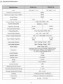
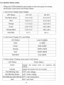
2-3. Electrical Performance
"',
>,<
Splfi.tjon
Item
Continuous
,'.
,.....>"..>.",.."
.,.
WF-600TD-112
.,'.
WF-600TD-124
600W
Output Power
Maximum Output Power (3Min.)
680W
Surge Rating
800W
24V
12V
Input Voltage
100/110 /120V
Output Voltage / Frequency
(Switch Selectable)
:t: 3%
50/60Hz +/- 0.05%
Efficiency (full load)
87.0%
90.0%
No Load Current Draw
0.87A
0.43A
Pure Sine Wave (THD <3%)
Output Waveform
cos
Power Factor Allowed
100/110
Output Voltage Regulation
(j -900
/120V
cos (j +900
RMS -10%/+4%
10.5-15
21.0-30
VDC
VDC
Input Voltage Regulation
Input Level Indicator
Load Level Indicator
Red / Orange / Green
LED
Red / Orange / Green
LED
Power Status
Red / Green LED
Protection
Overload, Short Circuit, Reverse Polarity (Fuse),
Over/Under Input Voltage, Over Temperature.
AC Inout Circuit Breaker, GFCI.
Circuit Breaker
7Amp
Transfer switch
1OAmp
48
Transfer Time
msec.
Safety
UL458
EMC
FCC Class B
Remote Control
YES
Synchronous AC transfer
YES
Operating Temperature Range
0 - 40De
Storage Temperature Range
-30De to 70De
Cooling
Loading controlled cooling fan
Dimensions
11.42 (L) x 7.05 (W) x 3.15 (H) Inch
Weight
3.3 kgs. / 6.6 Lbs.
5
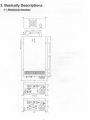
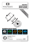
3. Basically Descriptions
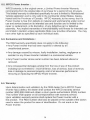
3-1 Mechanical drawinfJ.s
1
0
§I @ r
'C INPUT
A~G'I'X3C SJT AC CD"
~(
n~
1
T
~~
~
N
d
1
n
J
~
~~~~~~~~~~~~~~~~~~~~~~~~~~~~~~~~
~7D5'~~
I
I
610
§:§:"?6
~- [Qj="
[]J~
~Q 1~
I
~
1
HARD"IRE
I
~
I
6ID
;;:~"?6
:i-Inl=" Inl~ t
~;;~;i
GFCI
6
i
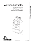
3-2 The Fronteanel
~
interface
.1
6.10
POWERSTATUS
I
l'E,;),iLDOO
COAD
LEVEL
J
POWER
g
ON
~
OFF
REMOTE
:~~~TE
IPNUT r,
-v
96 ~
OFF
REMOTE
AC
@]
1
"I
6.10
PDWER ON
g
OUTPUT
~
D ~DDD
REMnTE
PORT
[d
[ID
NEG-
~
~
In
M
~
LOAD LEVEL
*
POS+
~~
POWER "'TUS
LEVEL
I
~~:~~IT
BREAKET
I::::J
AC OUTPUT
~
n
[ID
NEG-
~
AC
AC
INPUT
CIRCUIT
BREAKET
POS+
~
I
~
(Y)
1
3-2-1. Power ON / OFF / REMOTE switch:
If you use a remote control unit, put the "on/off" switch to "remote".
3-2-2. AC input Circuit Breaker:
The lAmp circuit breaker protects the model from overload. When an
overland condition exists, the circuit breaker stops to supply output AC
grid power. To reset, push the circuit breaker switch and then the
model will be back to a normal operation, the source fault should be
corrected prior reset.
3-2-3 Remote port: Connect RJ-11 wiring with remote control unit.
3-2-4. Battery terminals:
Connect 12V (24V) batteries or other 12V / (24V) power sources.
3-2-5. Connect chassis ground terminal to earth.
3-3 The rear /2.anel interface
AC INPUT
n=~
,CQ
3-3-1. Ventilation:
Do not obstruct, allows at least 2 to 3 inches of clearance for airflow.
3-3-2. AC input: (source)
Plug into AC source directly.
8
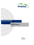
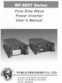
3-4 The Remote Controll2.anel
0
0
Inverter Status
( INTERNAl)
PIN
--------
I
JUMPER
@
Solid Red
Inverting
Blinking Fast - - - - - - R.O.F Acting
Blinking Slow- - - Ignition Lockou
,i;17\l
iO"JyJ
0
AUX,+12V
8
-@
INVERTER REMOTE
0
0
WFCO
Remote controlis a basic ONIOFF remote control.
*
The LED that glows steadily red when the Inverter is on.
* The LED
* The LED
Blinkingfast when the R.O.F is presented.
Blinkingslow when the Ignition Lockout function is
presented.
- The Jumper wirethat is placed inside the remote control and decides to present
either the R.O.F or Ignition lockout function.
* Pin jumper "Open"- R.O.F.
* Pin Jumper "Short"- Ignitionlockout function.
- The wiremust be placed witha properly sized 12 Voltfuse.
-Connect RJ-11 wire withthe remote port in front of panel.
* Ignition Lockout function-The Ignition lockout function is to turn the
Inverter OFF when the auxiliaryinput wiringconnects withthe
ACC and 12 Voltsis applied.
* R. O. F -The R.O.F (Return override function) is to turn the Inverter
ON when the auxiliaryinput wiringconnects withthe reverse gear
Shift and 12 Voltsis applied.
9
4. Installation
&
WARNING!
Shock Hazard. Before proceeding further, carefully
check to see if the WF-600T Inverter connect to batteries,
and every electrical sources wiring is disconnected.
Do not connect output terminals of the WF-600T Inverter
to incoming AC source.
4-1 AC Safety Grounding:
During the AC wiring installation, AC input and output grounding are
connected to the inverter. The AC input grounding must connect to the
incoming grounding of your AC utility sources and the AC output grounding
should go to the grounding point for your loads. (for example, a distribution
panel ground bus ).
Neutral Grounding (GFCI'S):
The neutral conductor of the AC output circuit of the WF-600T Inverter is
Automatically connected to the safety ground during inverter operation.
This conforms to National Electrical Code requirements that derived AC
sources separately (such as inverter and generators) have their neutral
conductors tied to ground in the same way that the neutral conductor from
the utility is tied to ground at the AC breaker panel.
For models configured with a transfer relay,while AC utility powers
presenting and he WF-600T Inverter is in bypass mode, this connection
(neutral of the WF-600T Inverter's AC output to input safety ground) is not
presented so that the utility neutral is only connected to ground at your
breaker panel, as required.
4-2 Ground Fault Circuit Interrupters (GFCI):
Recreational Vehicles Installations (for North American approvals) will require
GFCI protection, all branch circuits connected to the AC output hardwire terminal
is equipped WF-600T Inverter. In addition, electrical codes require GFCI
protection of certain receptacles in residential installations.
While the pure sine wave output of the WF-600T Inverter is equivalent to the
waveform provided by utilities, compliance with UL standards requires us to
test and recommend specific GFCI.
WFCO has tested the following GFCI-protected 20A receptacles, UL listed, Pass
& Seymour,type no. 2091-W & 2094-W , and found that they functioned properly
when connected to the output of the WF-600T Inverter.
10
4-3 Hard-wire Installation
To make AC wiring connections:
4-3-1. The AC wiring compartment is located on the front panel of the
WF-600T. Remove the AC wiring compartment cover to gain access
to the AC terminal.
4-3-2. Connect to the AC output wiring to the WF-600T AC output terminals.
Terminalto wiring connections refer to the following mentions:
Terminal
Wire color
Line (L)
Black
Neutral (N)
White
Ground
Green / Yellow or
Bare copper
Wire length I gauge
Within 16 feet! AWG# 1618
16
32 feet / AWG# 1416
4-3-3. After wiring, double check and review all connections to make sure
the wires are in correct terminals and the terminals are tight up.
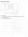
4-4 Making DC Wiring Connections:
Following procedure for connections between the battery cables and the
DC input terminals on the WF-600T Inverter. The cables should be high
quality copper wiring and keep cable length as short as possible, the
maximum length is 6 feet that plenty handle the current required from the
electrical codes or regulations.
If cables are not an adequate gauge ( too narrow or much longer), the
inverter performance decreased, DC voltage drop such as poor surge
capability, low input voltage warnings and shutdowns will be caused
frequency so the Longer and narrower cables are used; the greater voltage
drop is caused.
Battery cable fusing --- A fuse is required by the National Electrical Code
(NEe) to protect the battery and cables, A UL listed DC rated slow blow
fuse must be installed in positive battery cable, within 18 inches of the
battery.
11
VFCO recommends the following cables for an optimum inverter performance.
Model No
Wire AWG
Inline Fuse
WF-600TD-112
#4
100A
WF-600TD-124
#6
50A
WF-600T
-."'--,
...,,"
~-o9°
~~
fUl--Irll"
I':='J~
1
lJ::IJ=';
~~ - r--
BATTERY
WARNING!
&
.
The installation of a fuse must be on positive cable.
Failure to place a fuse on "+" cables running between the
Inverter and battery may cause damage to the inverter
and will void warranty.
12
5. Operation:
To operate the WF-600T series, turn it on by using the ON/OFF/REMOTE
switch. The inverter is now ready to deliver AC power to your loads. If you
are loading several appliances, turn them on separately after the inverter
switch on; this process is to avoid the power inverter delivers the starting
current once to all the loads.
5-1. Controls and indicators:
The ON/OFF switch is turns on/oft the control circuit of the power
inverter. If connect to power inverter, the WF-600T Inverter operates
input voltage ranges as follows:
10.5 to 15.0 VDC for 12V models
21.0 to 30.0 VDC for 24V models
The WF-600T Inverter indicates DC voltage status as follows:
Model
DC Input over
DC Input under
DC Input under
voltage shut-down voltage alarm voltage shut-down
WF-600T-112
15.3
11.0
10.5
WF-600T-124
30.6
22.0
21.0
13
5-2. System Status LEDs.
There are 3 LED indicators are located on the front panel of inverter,
Input Level, Load Level, and Power status.
1. Input Level: Display Input Voltage
LED Status
DC 12V
DC 24V
Red Blink (slow)
10.5-10.9
21.0-21.8
Red
10.9-11.3
21.8-22.6
Orange
11.3-12.0
22.6-24.0
Green
12.0-14.0
24.0-28.0
Orange Blink
14.0-14.7
28.0-29.4
Red Blink
14.7 t
29.4
t
2. Load Level: Display AC Load Watts
LED Status
Load Condition
Dark
0-30W
Green
30W-200W
Orange
200W-450W
Red
450W-580W
Red Blink
Over 580W
3. Power status: Display power good / fault status
LED Status
Power Status
Green
Supply AC power from an external AC
source
Orange
Supply AC power from an inverter.
Red Blinking Fast
OVP: over voltage
Red Blinking Slowly
UVP: under voltage
Red Blinking Intermittently OTP: over temperature
Red
OLP: over load
14
fi.
Information
I
I
I
6-1. Troubleshooting:
&
WARNING
Do not open or disassemble the WF-600T Inverter.
Attempting to service the unit may result a risk,
electrical shock or fire.
Problems and Symptoms
Possible Cause
No output voltage, the LED glows RED light.
Solutions
a. Power status light is
blinked fast.
Over input voltage.
Check input voltage
Reduce input voltage.
b. Power status light is
blinked slowly.
Low input voltage.
Recharge battery.
Check connections
and cable.
c. Power status light is
blinked Intermittently.
Thermal shutdown
Improve ventilation.
Make sure ventilation,
openings in inverter
are not obstructed.
Reduce ambient
temperature.
d. Power status light is
glowed steadily.
Short circuit, Wiring
error.
Over Loading
Check AC wiring
for short circuit.
Reduce load.
15
6-2. WFCO Power Inverter:
WFCO E3xtends,
to the original owner, a Limited Power Inverter Warranty
commencing from the original date of purchase for a period of two (2) years.
This limited warranty is extended specifically for and is limited to Recreational
Vehicle application and is only valid in the continental United States, Alaska,
Hawaii and the Provinces of Canada. WFCO warrants, to the owner, that it's
Power Inverter is free from defects in material and workmanship under normal
use and service based on its intended use and function and is limited to the
repair or replacement, at its discretion, of any defective part or defective
assembly. Any implied warranties of merchantability and fitness for intended use
are limited in duration unless applicable State Law provides otherwise. You may
have other right as specified by each individual state.
6-3. Exclusions and limitations:
The OEM warranty specifically does not apply to the following:
Any Power Inverter that has been repaired or altered by an
unauthorized person.
*
* Any damage caused by misuse, faulty installation, testing, negligence or
accident or any Power Inverter installed in a commercial vehicle.
*Any Power Inverter whose serial number has been defaced altered or
removed.
* Any consequential damages arising from the loss of use of the product
including but not limited to : inconvenience, loss of service, loss of revenue,
loss or damage to personal property, cost of all services performed in
removing or replacing the WFCO Power Inverter.
6-4. Warranty:
Upon determination and validation by the OEM dealer that a WFCO Power
Inverter has a defect, the dealer shall contact the WFCO warranty service
number (800) 900-2468 and obtain a return goods authorization (RGA) number.
This number shall appear on all correspondence with warranty service.
Upon validation warranty service shall replace the Power Inverter with a
like product. The RGA number shall also be placed on the outside of the carton
used to return the product for ease of identification. Do not mark on the
Power Inverter.
16