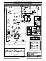
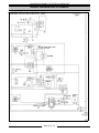
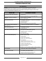
1
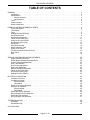
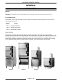
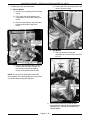
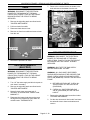
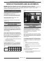
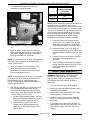
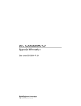
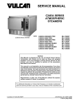
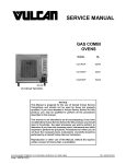
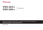
SERVICE MANUAL
MODEL VSX3E SHOWN
VSX SERIES CONVECTION STEAMERS
(ELECTRIC AND GAS)
VSX3E
VSX3E
VSX4E
VSX5E
VSX7EC
VSX7EO
ML-52396
ML-52397
ML-52398
ML-52399
ML-114822
ML-114821
VSX10EC
VSX10EO
VSX5G
VSX5GC
VSX7GC
VSX10GC
ML-114824
ML-114823
ML-114946
ML-114947
ML-114949
ML-114949
- NOTICE This Manual is prepared for the use of trained Vulcan Service
Technicians and should not be used by those not properly
qualified. If you have attended a Vulcan Service School for this
product, you may be qualified to perform all the procedures
described in this manual.
This manual is not intended to be all encompassing. If you have
not attended a Vulcan Service School for this product, you should
read, in its entirety, the repair procedure you wish to perform to
determine if you have the necessary tools, instruments and skills
required to perform the procedure. Procedures for which you do
not have the necessary tools, instruments and skills should be
performed by a trained Vulcan Service Technician.
Reproduction or other use of this Manual, without the express
written consent of Vulcan, is prohibited.
A product of VULCAN-HART
Form 24618 (Rev.A, March 2000)
LOUISVILLE, KY 40201-0696
VSX SERIES STEAMERS
TABLE OF CONTENTS
GENERAL . . . . . . . . . . . . . . . . . . . . . . . . . . . . . . . . . . . . . . . . . . . . . . . . . . . . . . . . . . . . . . . . . . . . . . . . . . . . .
Introduction . . . . . . . . . . . . . . . . . . . . . . . . . . . . . . . . . . . . . . . . . . . . . . . . . . . . . . . . . . . . . . . . . . . . . . . .
Specifications . . . . . . . . . . . . . . . . . . . . . . . . . . . . . . . . . . . . . . . . . . . . . . . . . . . . . . . . . . . . . . . . . . . . . .
Electric Steamers . . . . . . . . . . . . . . . . . . . . . . . . . . . . . . . . . . . . . . . . . . . . . . . . . . . . . . . . . . . . . . . .
Gas Steamers . . . . . . . . . . . . . . . . . . . . . . . . . . . . . . . . . . . . . . . . . . . . . . . . . . . . . . . . . . . . . . . . . .
Tools . . . . . . . . . . . . . . . . . . . . . . . . . . . . . . . . . . . . . . . . . . . . . . . . . . . . . . . . . . . . . . . . . . . . . . . . . . . . .
Control Location . . . . . . . . . . . . . . . . . . . . . . . . . . . . . . . . . . . . . . . . . . . . . . . . . . . . . . . . . . . . . . . . . . . . .
Water Conditioning . . . . . . . . . . . . . . . . . . . . . . . . . . . . . . . . . . . . . . . . . . . . . . . . . . . . . . . . . . . . . . . . . .
3
3
4
4
4
5
5
5
REMOVAL AND REPLACEMENT OF PARTS . . . . . . . . . . . . . . . . . . . . . . . . . . . . . . . . . . . . . . . . . . . . . . . . . 6
Covers and Panels . . . . . . . . . . . . . . . . . . . . . . . . . . . . . . . . . . . . . . . . . . . . . . . . . . . . . . . . . . . . . . . . . . . 6
Thermostats . . . . . . . . . . . . . . . . . . . . . . . . . . . . . . . . . . . . . . . . . . . . . . . . . . . . . . . . . . . . . . . . . . . . . . . . 7
Timer . . . . . . . . . . . . . . . . . . . . . . . . . . . . . . . . . . . . . . . . . . . . . . . . . . . . . . . . . . . . . . . . . . . . . . . . . . . . . 9
Heating Elements (Electric) . . . . . . . . . . . . . . . . . . . . . . . . . . . . . . . . . . . . . . . . . . . . . . . . . . . . . . . . . . . . 9
Gas Solenoid Valve . . . . . . . . . . . . . . . . . . . . . . . . . . . . . . . . . . . . . . . . . . . . . . . . . . . . . . . . . . . . . . . . . . 9
Gas Pressure Regulator . . . . . . . . . . . . . . . . . . . . . . . . . . . . . . . . . . . . . . . . . . . . . . . . . . . . . . . . . . . . . . 11
Flame Sense Probe (Gas) . . . . . . . . . . . . . . . . . . . . . . . . . . . . . . . . . . . . . . . . . . . . . . . . . . . . . . . . . . . . 11
Water Level Control Board . . . . . . . . . . . . . . . . . . . . . . . . . . . . . . . . . . . . . . . . . . . . . . . . . . . . . . . . . . . . 11
Hot Surface Ignitor (Gas) . . . . . . . . . . . . . . . . . . . . . . . . . . . . . . . . . . . . . . . . . . . . . . . . . . . . . . . . . . . . . 12
Gas Burner . . . . . . . . . . . . . . . . . . . . . . . . . . . . . . . . . . . . . . . . . . . . . . . . . . . . . . . . . . . . . . . . . . . . . . . 12
Gas Ignition Module . . . . . . . . . . . . . . . . . . . . . . . . . . . . . . . . . . . . . . . . . . . . . . . . . . . . . . . . . . . . . . . . . 13
Steam Generator Tank . . . . . . . . . . . . . . . . . . . . . . . . . . . . . . . . . . . . . . . . . . . . . . . . . . . . . . . . . . . . . . 13
Water Level Probes . . . . . . . . . . . . . . . . . . . . . . . . . . . . . . . . . . . . . . . . . . . . . . . . . . . . . . . . . . . . . . . . . 14
Fill and Cold Water Solenoid Valves . . . . . . . . . . . . . . . . . . . . . . . . . . . . . . . . . . . . . . . . . . . . . . . . . . . . 15
Drain Valve . . . . . . . . . . . . . . . . . . . . . . . . . . . . . . . . . . . . . . . . . . . . . . . . . . . . . . . . . . . . . . . . . . . . . . . 16
Door . . . . . . . . . . . . . . . . . . . . . . . . . . . . . . . . . . . . . . . . . . . . . . . . . . . . . . . . . . . . . . . . . . . . . . . . . . . . . 18
SERVICE PROCEDURES AND ADJUSTMENTS . . . . . . . . . . . . . . . . . . . . . . . . . . . . . . . . . . . . . . . . . . . . . .
Steam Generator Cleaning . . . . . . . . . . . . . . . . . . . . . . . . . . . . . . . . . . . . . . . . . . . . . . . . . . . . . . . . . . .
Delime Board Operation and Adjustment . . . . . . . . . . . . . . . . . . . . . . . . . . . . . . . . . . . . . . . . . . . . . . . . .
Control Thermostat Adjustment . . . . . . . . . . . . . . . . . . . . . . . . . . . . . . . . . . . . . . . . . . . . . . . . . . . . . . . .
Drain Tank Manually . . . . . . . . . . . . . . . . . . . . . . . . . . . . . . . . . . . . . . . . . . . . . . . . . . . . . . . . . . . . . . . .
Door Sealing Adjustment . . . . . . . . . . . . . . . . . . . . . . . . . . . . . . . . . . . . . . . . . . . . . . . . . . . . . . . . . . . . .
Door Latch Adjustment . . . . . . . . . . . . . . . . . . . . . . . . . . . . . . . . . . . . . . . . . . . . . . . . . . . . . . . . . . . . . . .
Manifold Pressure Adjustment . . . . . . . . . . . . . . . . . . . . . . . . . . . . . . . . . . . . . . . . . . . . . . . . . . . . . . . . .
Flame Sense Probe (Gas) . . . . . . . . . . . . . . . . . . . . . . . . . . . . . . . . . . . . . . . . . . . . . . . . . . . . . . . . . . . .
Hot Surface Ignitor (Gas) . . . . . . . . . . . . . . . . . . . . . . . . . . . . . . . . . . . . . . . . . . . . . . . . . . . . . . . . . . . . .
Heating Element (Electric) . . . . . . . . . . . . . . . . . . . . . . . . . . . . . . . . . . . . . . . . . . . . . . . . . . . . . . . . . . . .
20
20
20
20
21
22
22
23
24
25
25
ELECTRICAL OPERATION . . . . . . . . . . . . . . . . . . . . . . . . . . . . . . . . . . . . . . . . . . . . . . . . . . . . . . . . . . . . . .
Component Function . . . . . . . . . . . . . . . . . . . . . . . . . . . . . . . . . . . . . . . . . . . . . . . . . . . . . . . . . . . . . . . .
Component Location . . . . . . . . . . . . . . . . . . . . . . . . . . . . . . . . . . . . . . . . . . . . . . . . . . . . . . . . . . . . . . . .
Electric Models . . . . . . . . . . . . . . . . . . . . . . . . . . . . . . . . . . . . . . . . . . . . . . . . . . . . . . . . . . . . . . . . .
Gas Models . . . . . . . . . . . . . . . . . . . . . . . . . . . . . . . . . . . . . . . . . . . . . . . . . . . . . . . . . . . . . . . . . . .
Water Level Control Operation . . . . . . . . . . . . . . . . . . . . . . . . . . . . . . . . . . . . . . . . . . . . . . . . . . . . . . . .
Sequence of Operation . . . . . . . . . . . . . . . . . . . . . . . . . . . . . . . . . . . . . . . . . . . . . . . . . . . . . . . . . . . . . .
Electric Models . . . . . . . . . . . . . . . . . . . . . . . . . . . . . . . . . . . . . . . . . . . . . . . . . . . . . . . . . . . . . . . . .
Gas Models . . . . . . . . . . . . . . . . . . . . . . . . . . . . . . . . . . . . . . . . . . . . . . . . . . . . . . . . . . . . . . . . . . .
Schematic Electric Steamers . . . . . . . . . . . . . . . . . . . . . . . . . . . . . . . . . . . . . . . . . . . . . . . . . . . . . . . . . .
Wiring Diagram Electric Steamers . . . . . . . . . . . . . . . . . . . . . . . . . . . . . . . . . . . . . . . . . . . . . . . . . . . . . .
Schematic Gas Steamers . . . . . . . . . . . . . . . . . . . . . . . . . . . . . . . . . . . . . . . . . . . . . . . . . . . . . . . . . . . .
Wiring Diagram Gas Steamers . . . . . . . . . . . . . . . . . . . . . . . . . . . . . . . . . . . . . . . . . . . . . . . . . . . . . . . .
26
26
28
28
29
30
30
30
32
34
35
36
37
TROUBLESHOOTING . . . . . . . . . . . . . . . . . . . . . . . . . . . . . . . . . . . . . . . . . . . . . . . . . . . . . . . . . . . . . . . . . . 38
All Models . . . . . . . . . . . . . . . . . . . . . . . . . . . . . . . . . . . . . . . . . . . . . . . . . . . . . . . . . . . . . . . . . . . . . . . . 38
Gas Models Only . . . . . . . . . . . . . . . . . . . . . . . . . . . . . . . . . . . . . . . . . . . . . . . . . . . . . . . . . . . . . . . . . . . 40
© VULCAN 2000
Page 2 of 40
VSX SERIES STEAMERS -GENERAL
GENERAL
INTRODUCTION
General
This manual is applicable for all models listed on the cover page. Several models are pictured below for
reference.
Serial Number Break
Listed below, are the beginning serial numbers for each model when the solid state water level control (three
probe design) was added.
MODEL
SERIAL
VSX-3
AP100704-9Q-4565
VSX-4
AP1007141-9Q-4615
VSX-5
AP1007555-11Q-5522
Steam Cooking
Pressure-less steamers offer an efficient way to produce many foods in small portions or larger batches.
Pressure-less, convection steam cooking will steam cook fresh foods or will steam defrost and cook frozen foods
providing the maximum color, flavor and nutritional value with the least expenditure of energy and labor. The
pressure-less steaming compartment allows the operator to open and close the door, anytime during a cooking
cycle. The steam supply will shut off when the door is opened, then re-start when the door is closed.
VSX7EC
VSX7EO
VSX5GC
Page 3 of 40
VSX5G
VSX SERIES STEAMERS -GENERAL
SPECIFICATIONS
Model Designations (based on 2.5 inch pan depth)
VSX3 - 3 pan unit.
VSX4 - 4 pan unit.
VSX5 - 5 pan unit.
VSX7 - Combination VSX3 and VSX4 unit.
VSX10 - Combination of two VSX5 units.
Electric Steamers
AMPERAGE
3 PHASE
MODEL
VSX3E
1 PHASE
TOTAL
208V 240V 480V 208V 240V
KW
7.5 std.
20.9
18.1
9.0
36.1
31.3
10.0 opt. 27.8
24.1
12.1
48.1
41.7
VSX4E
10.0
27.8
24.1
12.1
48.1
41.7
VSX5E
15.0
41.6
36.2
18.1
72.2
62.5
VSX7E
17.5
48.7
42.2
21.1
VSX10E
30
83.2
72.4
36.2
Gas Steamers
INPUT
BTU/HR
MANIFOLD
PRESSURE
(INCHES W.C.)
LINE PRESSURE
(INCHES W.C.)
NATURAL
LOAD
(WATTS)
PROPANE
MAX
MODEL
NAT.
PROP.
NAT.
PROP.
RECOMMEND
MIN
RECOMMEND
MIN
VSX5G
45,000
45,000
3.5
5.0
7.0
5.0
11.0
7.0
VSX5GC
45,000
45,000
3.5
5.0
7.0
5.0
11.0
7.0
AMPS
(MAX)
120V
60HZ
180
1.5
180
1.5
14.0
VSX7GC
90,000
90,000
3.5
5.0
7.0
5.0
11.0
7.0
360
3.0
VSX10GC
90,000
90,000
3.5
5.0
7.0
5.0
11.0
7.0
360
3.0
Water Supply
Supply pressure should be ........................
In line strainer for supply line (Supplied)
Total dissolved solids (TDS)* ....................
Total alkalinity ...........................................
Silica .........................................................
Chloride ....................................................
PH factor ...................................................
(*17.1 ppm = 1 grain of hardness)
20-80 psig
less than 60 ppm
less than 20 ppm
less than 13 ppm
less than 30 ppm
7 to 8
Page 4 of 40
VSX SERIES STEAMERS -GENERAL
TOOLS
WATER CONDITIONING
Standard
Standard set of hand tools.
VOM with an AC current tester (any quality
VOM with a sensitivity of at least 20,000 ohms
per volt can be used).
Gas leak checking equipment.
Special
CLR Treatment Kit (p/n 817634) - Used to
remove Calcium/Lime/Rust from a steam
generator tank.
CONTROL LOCATION
Furnishing the steam generator with soft water to
reduce scale formation is important. Scale formation
will reduce steam output, cause premature
component failure, and shorten equipment life. Most
water supplies contain scale producing minerals
such as Calcium and Magnesium. As steam is
generated, the minerals remain and dissolve into
the water. As the concentration of these minerals
increases past a certain point, they precipitate from
the water and coat the inside of the tank, heating
elements, thermostat bulbs and water level probes.
Because of the high temperature of these surfaces,
the precipitated minerals bake onto them and
become very difficult to remove.
This phenomenon causes several problems:
1. Reduce the heat transfer efficiency of the
heaters.
2. Cause premature failure of the heaters.
3. Water level probes will give false readings.
4. Thermostat bulbs will sense temperature
incorrectly.
These problems are common to any manufacturer's
steamer regardless of design, but they can all be
prevented by furnishing the steam generator tank
with soft water. Vulcan recommends the water
contain less than 60ppm of “total dissolved solids”
(TDS) and have a PH factor between 7 to 8. These
water properties can be achieved by using a
properly maintained water softener.
Other chemical properties in water supplies can also
affect good steam generation and vary from within
each state and locality.
The water level probes in the steam generator tank
use ions in the water to detect the water level. Do
not use fully demineralized or de-ionized water
since it is "non conductive" and the water level can
not be detected.
NOTE: The use of strainers, or fibers will not
remove minerals from the water.
Therefore, it is recommended that a local water
treatment specialist be consulted before the
installation of any steam generating equipment.
(Gas Model Shown)
Steamers that operate over a long period of time
without the benefit of a water softener, which have
developed a heavy scale build up, should be
cleaned before using a water softener.
Page 5 of 40
VSX SERIES STEAMER - REMOVAL AND REPLACEMENT OF PARTS
REMOVAL AND REPLACEMENT OF PARTS
B. Remove the screws that secure the flue to
the tank and lift it off.
COVERS AND PANELS
WARNING: DISCONNECT THE ELECTRICAL
POWER TO THE MACHINE AT THE MAIN
CIRCUIT BOX. PLACE A TAG ON THE CIRCUIT
BOX INDICATING THE CIRCUIT IS BEING
SERVICED.
Right Side Panel
1. Remove screws from the bottom of the panel.
2. Slide panel down to clear the top cover.
2. Push up on the rear of the cover and slide the
top cover forward to clear the front edge.
3. Reverse procedure to install.
3. Lift the cover off the cabinet.
4. Reverse procedure to install.
Left Side and Rear Panel
1. Remove the top cover screws an disconnect the
utilities.
(Gas Model Shown)
Top Cover
1. Remove screws from the top rear of cover. If
steamer is a gas model, follow steps 1A and 1B.
A. Remove the screws at the base of the
exterior flue housing and lift off.
Page 6 of 40
VSX SERIES STEAMER - REMOVAL AND REPLACEMENT OF PARTS
2. Remove the screws at the bottom of panel.
replaced.
5. Remove screws that secure the thermostat.
3. Remove the lower access panels on the right
and left side of the unit to gain access to the
lower compartment.
4. Remove the screws Inside the lower
compartment that run along the top rear of the
base frame that secure the lip of the rear panel.
NOTE: Rear panel lip is “sandwiched” between the
base frame and the top lip of the small rear access
panel.
5. Pull the combination left side and rear panel off.
6. Reverse procedure to install.
THERMOSTATS
WARNING: DISCONNECT THE ELECTRICAL
POWER TO THE MACHINE AT THE MAIN
CIRCUIT BOX. PLACE A TAG ON THE CIRCUIT
BOX INDICATING THE CIRCUIT IS BEING
SERVICED.
6. If replacing the control thermostat, fully loosen
the compression nut, sliding it away from tank,
then remove the bulb.
1. Turn “off” the water supply and allow hot parts to
cool down if necessary.
2. Remove the right side panel as outlined under
"COVERS AND PANELS".
NOTE: When installing, do not over tighten as
thermostat calibration and/or damage to thermostat
may occur.
3. Manually drain the steam generator tank if
necessary, as outlined in "DRAIN TANK
MANUALLY”.
4. Disconnect the lead wires from thermostat being
Page 7 of 40
VSX SERIES STEAMER - REMOVAL AND REPLACEMENT OF PARTS
7. If replacing the high limit thermostat:
5) Pull the bulb from its holding sleeve and
remove from the heater.
A. Electric Models
1) Remove nut on capillary tube hold down
clamp.
2) Fully loosen the small capillary tube
compression nut and slide it away from
heater.
3) Remove large capillary nut from heater
base plate and slide it away from
heater.
B. Gas Models
1) Remove the nuts securing the
thermostat to the tank surface plate and
lift it off.
4) Remove the remaining nuts that secure
heater to the tank and pull heater out
just enough to expose the holding
sleeve on the element and the bulb.
NOTE: Cut the wire ties holding the heater lead
wires together so the heating element can be pulled
out without disconnecting the lead wires.
8. Reverse the procedure to install the new
thermostat and check for proper operation as
outlined under "CONTROL THERMOSTAT
ADJUSTMENT".
Page 8 of 40
VSX SERIES STEAMER - REMOVAL AND REPLACEMENT OF PARTS
5. Remove the nuts that secure the heater to the
tank and remove the heater from the unit.
TIMER
WARNING: DISCONNECT THE ELECTRICAL
POWER TO THE MACHINE AT THE MAIN
CIRCUIT BOX. PLACE A TAG ON THE CIRCUIT
BOX INDICATING THE CIRCUIT IS BEING
SERVICED.
1. Remove the right side panel as outlined under
"COVERS AND PANELS".
2. Pull timer knob from shaft.
3. Disconnect lead wires to timer.
4. Remove nut from timer shaft and remove timer
from the unit.
6. Reverse procedure to install.
GAS SOLENOID VALVE
WARNING: DISCONNECT THE ELECTRICAL
POWER TO THE MACHINE AT THE MAIN
CIRCUIT BOX. PLACE A TAG ON THE CIRCUIT
BOX INDICATING THE CIRCUIT IS BEING
SERVICED.
5. Reverse the procedure to install.
HEATING ELEMENTS
(ELECTRIC)
WARNING: SHUT OFF THE GAS SUPPLY
BEFORE SERVICING THE UNIT.
WARNING: DISCONNECT THE ELECTRICAL
POWER TO THE MACHINE AT THE MAIN
CIRCUIT BOX. PLACE A TAG ON THE CIRCUIT
BOX INDICATING THE CIRCUIT IS BEING
SERVICED.
WARNING: ALL GAS JOINTS DISTURBED
DURING SERVICING MUST BE CHECKED FOR
LEAKS. CHECK USING A SOAP AND WATER
SOLUTION (BUBBLES). DO NOT USE AN OPEN
FLAME.
1. Turn “off” the water supply and allow hot parts to
cool down if necessary.
A. BEFORE LIGHTING UNIT, CHECK ALL
JOINTS PRIOR TO THE GAS VALVE
(SOLENOID).
2. Remove the right side panel as outlined under
"COVERS AND PANELS".
3. Manually drain steam generator tank if
necessary, as outlined under "DRAIN TANK
MANUALLY".
4. Disconnect the heater lead wires and remove
the high limit thermostat bulb from heater as
outlined under “THERMOSTATS”.
B. CHECK ALL JOINTS BEYOND GAS
VALVE (SOLENOID) AFTER THE UNIT
HAS LIT.
1. Remove the right side panel as outlined under
"COVERS AND PANELS".
2. Cut the wire ties around “wire bundle” and trace
the solenoid wires to there terminations and
remove.
Page 9 of 40
VSX SERIES STEAMER - REMOVAL AND REPLACEMENT OF PARTS
3. Loosen the compression nuts on the flexible gas
line then remove line from the gas solenoid
valve and manifold.
B. Loosen the compression nuts on the
“condenser feed” and “tank feed” water lines
and place the lines to the side.
NOTE: If necessary, loosen the remaining
compression nut on the “cold water condenser”
solenoid and rotate it out of the way.
6. Open the lower cabinet base door to gain
access the gas solenoid valves.
(VSX5G SHOWN)
4. If removing gas valve from a single unit,
proceed to step 5. If removing gas solenoid
valve from a double unit, proceed to step 6.
5. Turn “off” the water supply to the “tank fill” and
“cold water condenser” solenoids and
disconnect the fittings (bulkhead union) on the
opposite end of the incoming water
connections.
A. To access the compression fittings for the
incoming water connection, remove the
small access panel to the lower
compartment.
7. Remove the gas solenoid valve from the pipe
nipple below it.
8. Reverse procedure to install and check unit for
proper operation.
Page 10 of 40
VSX SERIES STEAMER - REMOVAL AND REPLACEMENT OF PARTS
GAS PRESSURE REGULATOR
FLAME SENSE PROBE (GAS)
WARNING: DISCONNECT THE ELECTRICAL
POWER TO THE MACHINE AT THE MAIN
CIRCUIT BOX. PLACE A TAG ON THE CIRCUIT
BOX INDICATING THE CIRCUIT IS BEING
SERVICED.
WARNING: DISCONNECT THE ELECTRICAL
POWER TO THE MACHINE AT THE MAIN
CIRCUIT BOX. PLACE A TAG ON THE CIRCUIT
BOX INDICATING THE CIRCUIT IS BEING
SERVICED.
WARNING: SHUT OFF THE GAS SUPPLY
BEFORE SERVICING THE UNIT.
WARNING: SHUT OFF THE GAS SUPPLY
BEFORE SERVICING THE UNIT.
WARNING: ALL GAS JOINTS DISTURBED
DURING SERVICING MUST BE CHECKED FOR
LEAKS. CHECK USING A SOAP AND WATER
SOLUTION (BUBBLES). DO NOT USE AN OPEN
FLAME.
A. BEFORE LIGHTING UNIT, CHECK ALL
JOINTS PRIOR TO THE GAS VALVE
(SOLENOID).
B. CHECK ALL JOINTS BEYOND GAS
VALVE (SOLENOID) AFTER THE UNIT
HAS LIT.
1. Remove the right side panel as outlined under
"COVERS AND PANELS".
2. Remove the gas solenoid valve as outline under
“GAS SOLENOID VALVE”.
1. Cut the wire ties around “wire bundle” and trace
the Flame Sense Probe (FSP) wire to an in-line
splice (butt connector) and cut the wire close to
the connector.
2. Remove the screw holding the flame sense
probe onto the mounting bracket and lift out.
3. Reverse the procedure to install a new probe
then check FSP for proper operation as outlined
under “FLAME SENSE PROBE”.
NOTE: The opposite end of the in-line splice will
have to be cut close to the connector and the wire
insulation stripped back approximately 0.250 inch to
install a new connector.
3. Remove the gas pressure regulator from the
pipe nipple below it.
WATER LEVEL CONTROL
BOARD
WARNING: DISCONNECT THE ELECTRICAL
POWER TO THE MACHINE AT THE MAIN
CIRCUIT BOX. PLACE A TAG ON THE CIRCUIT
BOX INDICATING THE CIRCUIT IS BEING
SERVICED.
1. Remove the right side panel as outlined under
"COVERS AND PANELS".
2. Disconnect the lead wires from the water level
control board (WLC).
3. Remove mounting screws.
4. Move board to the left and rotate outwards when
removing, to clear wire bundle.
5. Reverse the procedure to install, then check unit
for proper operation.
4. Reverse the procedure to install.
5. Adjust the gas regulator pressure as outlined
under “MANIFOLD PRESSURE
ADJUSTMENT”.
6. Check unit for proper operation.
Page 11 of 40
VSX SERIES STEAMER - REMOVAL AND REPLACEMENT OF PARTS
HOT SURFACE IGNITOR (GAS)
GAS BURNER
WARNING: DISCONNECT THE ELECTRICAL
POWER TO THE MACHINE AT THE MAIN
CIRCUIT BOX. PLACE A TAG ON THE CIRCUIT
BOX INDICATING THE CIRCUIT IS BEING
SERVICED.
WARNING: DISCONNECT THE ELECTRICAL
POWER TO THE MACHINE AT THE MAIN
CIRCUIT BOX. PLACE A TAG ON THE CIRCUIT
BOX INDICATING THE CIRCUIT IS BEING
SERVICED.
WARNING: SHUT OFF THE GAS SUPPLY
BEFORE SERVICING THE UNIT.
1. Remove the right side panel as outlined under
"COVERS AND PANELS".
1. Remove the right side panel as outlined under
"COVERS AND PANELS".
2. Cut the wire ties around “wire bundle” and trace
the wire for the Hot Surface Ignitor (HSI) to an
in-line splice (butt connector) and cut the wire
off close to the connector.
2. Remove the screws securing the burner
mounting bracket to the burner box frame.
3. Slide the burner forward enough to clear the gas
nozzles and lift it out.
3. Remove the screw that holds the flame sense
probe and ground terminal wire onto the
mounting bracket and lift out.
4. Reverse the procedure to install then check HSI
for proper operation as outlined under “HOT
SURFACE IGNITOR”.
NOTE: The opposite end of the in-line splice will
have to be cut, close to the connector and the wire
insulation stripped back approximately 0.250 inch to
install a new connector.
4. Remove the screws securing the burners to the
mounting bracket and lift the burners off.
5. Reverse procedure to install then check for
proper operation.
NOTE: When checking for proper operation, make
sure burner flame is not impinging on the opening of
the burner box.
Page 12 of 40
VSX SERIES STEAMER - REMOVAL AND REPLACEMENT OF PARTS
GAS IGNITION MODULE
WARNING: DISCONNECT THE ELECTRICAL
POWER TO THE MACHINE AT THE MAIN
CIRCUIT BOX. PLACE A TAG ON THE CIRCUIT
BOX INDICATING THE CIRCUIT IS BEING
SERVICED.
3. Manually drain steam generator tank if
necessary, as outlined under "DRAIN TANK
MANUALLY".
4. Disconnect the lead wire from each water level
probe and then remove probes from tank. Mark
probes accordingly for replacement.
1. Remove the right side panel as outlined under
"COVERS AND PANELS".
2. Disconnect the control wires by pulling off wire
harness connector located on the right side of
module.
3. Remove screws that secure the module to the
control board and lift off.
4. Reverse the procedure to install the new gas
ignition module then check for proper operation.
STEAM GENERATOR TANK
WARNING: DISCONNECT THE ELECTRICAL
POWER TO THE MACHINE AT THE MAIN
CIRCUIT BOX. PLACE A TAG ON THE CIRCUIT
BOX INDICATING THE CIRCUIT IS BEING
SERVICED.
(Electric Model Shown)
1. Turn “off” the water supply and allow hot parts to
cool down if necessary. On gas models, shut the
gas supply “off” to the unit.
2. Remove the right side panel and top cover as
outlined under "COVERS AND PANELS".
Page 13 of 40
VSX SERIES STEAMER - REMOVAL AND REPLACEMENT OF PARTS
5. Disconnect the steam lines on the top right and
left side of the tank, the water fill tube, the drain
line, then the delime line at the bottom left
corner.
7. Gas Model Only
A. Remove the burner assembly and place to
the side.
B. Remove the bolts that secure the manifold
to the burner box frame and place to the
side.
C. Remove the surface high limit and the
control thermostat bulb from the tank.
D. Remove the combination Left side and Rear
panel as outlined under “COVERS AND
PANELS”.
(Gas Model Shown)
6. Electric Models Only - For gas models proceed
to step 7.
A. Remove the heater lead wires, control and
high limit thermostat bulbs, then remove the
heater from the tank.
B. To remove tank, loosen the nut on the left
side mounting stud of the tank and remove
the two nuts from the mounting studs on the
right side of the tank.
8. Remove the nuts and washers from studs on
each side of the tank that secure it to the steam
cavity and lift the steam generator tank out.
9. Reverse procedure to install and check unit for
proper operation.
WATER LEVEL PROBES
WARNING: DISCONNECT THE ELECTRICAL
POWER TO THE MACHINE AT THE MAIN
CIRCUIT BOX. PLACE A TAG ON THE CIRCUIT
BOX INDICATING THE CIRCUIT IS BEING
SERVICED.
1. Remove the top cover as outlined under
"COVERS AND PANELS".
2. Disconnect the lead wire to water level probes.
(Electric Model Shown)
C. Push the right side of the tank toward the
rear of the unit enough to clear the studs
from the mounting bracket then, pull tank
toward the right to remove.
D. Reverse the procedure to install and check
unit for proper operation.
Page 14 of 40
VSX SERIES STEAMER - REMOVAL AND REPLACEMENT OF PARTS
3. Unscrew probes from steam generator tank.
3. Cut the wire ties around “wire bundle” and trace
the power wires for the solenoid valve being
serviced back to there terminations and remove.
4. Disconnect the fittings on each side of the valve
and remove the valve from the unit.
5. Reverse procedure to install.
(Gas Model Shown)
NOTE: Probe should be cleaned thoroughly.
Remove all accumulated deposits from the insulator
using a soft cloth.
(Electric Model)
NOTE: Do not use anything abrasive on the
insulators.
NOTE: If the probes are dirty, delime the unit after
assembling.
(Gas Model)
Disassembly
4. Reverse procedure to install.
NOTE: Perform a steam generator tank cleaning as
outlined under "STEAM GENERATOR TANK
CLEANING".
NOTE: It is recommended that the valve be
removed from the unit for cleaning to prevent
damage to the lines and fittings when the stem is
removed from the body.
1. Remove the coil assembly from the valve stem.
FILL AND COLD WATER
SOLENOID VALVES
2. Disconnect the fittings on each side of the valve
and remove it from the unit. Read note before
removing.
WARNING: DISCONNECT THE ELECTRICAL
POWER TO THE MACHINE AT THE MAIN
CIRCUIT BOX. PLACE A TAG ON THE CIRCUIT
BOX INDICATING THE CIRCUIT IS BEING
SERVICED.
Removal
NOTE: If a standard or adjustable spanner wrench
that fits these solenoids is available, the body of the
valve might be held with vise grips and then,
remove the stem with your spanner wrench. If this
can be done without damaging the line or fittings,
proceed to step 5.
3. Clamp the body of the valve in a vise.
1. Turn “off” the water supply to the steamer.
2. Remove the right side panel as outlined under
"COVERS AND PANELS".
4. Mark a scribe line on the stem nut to the valve
body for proper retightening.
Page 15 of 40
VSX SERIES STEAMER - REMOVAL AND REPLACEMENT OF PARTS
5. Use a hammer and punch to turn the stem
counterclockwise to remove the stem from the
body.
DRAIN VALVE
WARNING: DISCONNECT THE ELECTRICAL
POWER TO THE MACHINE AT THE MAIN
CIRCUIT BOX. PLACE A TAG ON THE CIRCUIT
BOX INDICATING THE CIRCUIT IS BEING
SERVICED.
Removal
1. Turn “off” the water supply to the steamer.
2. Remove the right side panel and top cover as
outlined under "COVERS AND PANELS".
3. Manually drain the steam generator tank if
necessary, as outlined under "DRAIN TANK
MANUALLY".
6. All parts are now accessible for inspection and
cleaning.
A. Check rubber seal on bottom of plunger.
B. Check plunger spring.
4. Disconnect the lead wires from the water level
control and the ground wire from the control
panel if necessary, to access the drain valve
connections.
5. Disconnect the fittings on each side of the valve
and remove the valve from the unit.
C. Check "O"ring in valve body.
D. Check ports in valve body.
6. Reverse procedure to install.
Disassembly
1. Turn “off” the water supply to the steamer.
2. Remove the right side panel as outlined under
"COVERS AND PANELS".
3. Manually drain the steam generator tank if
necessary, as outlined under "DRAIN TANK
MANUALLY".
4. Remove the cover from the drain valve motor.
7. Reverse procedure to install.
Page 16 of 40
VSX SERIES STEAMER - REMOVAL AND REPLACEMENT OF PARTS
5. Loosen the screws from the motor assembly
and lift up on the motor to remove it from the
valve body.
NOTE: When re-installing, place flat sides of ball
stem perpendicular to the inlet and outlet of the
drain valve. The valve will be in the open position
whenever power is removed from the motor.
6. Remove the screws from the cover plate and
remove the cover plate and ball assembly from
the valve body.
7. Reverse procedure to install.
Page 17 of 40
VSX SERIES STEAMER - REMOVAL AND REPLACEMENT OF PARTS
Gasket
DOOR
WARNING: DISCONNECT THE ELECTRICAL
POWER TO THE MACHINE AT THE MAIN
CIRCUIT BOX. PLACE A TAG ON THE CIRCUIT
BOX INDICATING THE CIRCUIT IS BEING
SERVICED.
Removal
1. Remove top cover as outlined under "COVERS
AND PANELS".
2. Open the door.
3. Pull hinge rod up.
1. Open the door.
2. Remove screws from the gasket plate.
3. Pull the gasket plate out from the door housing
and remove the gasket.
4. Position the new gasket on the gasket plate and
reverse the procedure to install. Adjust the door
as outlined under "DOOR SEALING
ADJUSTMENT".
NOTE: Do not over tighten gasket plate screws as
this will compress the gasket excessively and
interfere with proper door sealing.
4. Reverse the procedure to install, making sure
the door bushings are in place.
Page 18 of 40
VSX SERIES STEAMER - REMOVAL AND REPLACEMENT OF PARTS
Handle
Latch Assembly
1. Open the door.
1. Open the door.
2. Remove screws from the top and bottom of the
door.
2. Remove screws from the top and bottom of the
door.
3. Pull the “inner” door panel out from the door
housing with the gasket plate and gasket still
attached.
3. Pull the “inner” door panel out from the door
housing with the gasket plate and gasket still
attached.
4. Remove the screws from the side edge of the
door that secure the latch mechanism and
remove the latch from the door.
NOTE: When installing, the latch lever must rest on
top of the handle latch screw.
5. Reverse procedure to install.
4. Remove the nuts and spacers from the handle
screws and remove the handle from the door.
NOTE: When installing the spacers, the smaller
diameter fits into the slot in the door and the latch
lever must rest on top of the handle latch screw.
5. Reverse procedure to install.
Page 19 of 40
VSX SERIES STEAMER - SERVICE PROCEDURES AND ADJUSTMENTS
SERVICE PROCEDURES AND ADJUSTMENTS
WARNING: CERTAIN PROCEDURES IN THIS SECTION REQUIRE ELECTRICAL TEST OR
MEASUREMENTS WHILE POWER IS APPLIED TO THE MACHINE. EXERCISE EXTREME CAUTION AT ALL
TIMES. IF TEST POINTS ARE NOT EASILY ACCESSIBLE, DISCONNECT POWER, ATTACH TEST
EQUIPMENT AND REAPPLY POWER TO TEST.
STEAM GENERATOR CLEANING
NOTE: Factory default time set on the board is 100
hrs.
Follow the procedure as outlined in the "CLR
TREATMENT KIT" to remove the
Calcium/Lime/Rust build-up inside the tank, water
level probes, electric elements and drain system.
The CLR Kit contains, C.L.R. cleaner, funnel,
measuring cup, and " tubing.
G
In addition but not furnished in kit, rubber gloves
should be used.
DELIME BOARD OPERATION
AND ADJUSTMENT
The delime timer board tracks the cumulative
cooking hours and lights the delime light on the
control panel when the delime timer board reaches
a preset number of cooking hours. An LED on the
delime timer board lights indicating cook time hours
are accumulating.
After the delime timer board has accumulated the
preset number of cooking hours, the delime light will
light. It will stay lit until the power switch is moved to
the delime position or off. If the power switch is
turned “off” and then turned “on” without going to the
delime position, the delime light will relight.
1. To adjust the length of cooking hours before the
delime light will come on:
2. Access the delime timer board.
Position the switches in the “on” or “off” position to
obtain the desired hours. The number of switches
that are positioned “on” or “off” set the total hours. It
does not matter which individual switch is “on” or
“off”.
SWITCH
POSITION
CONTROL THERMOSTAT
ADJUSTMENT
The procedure outlined below is to adjust the
thermostat temperature setting to a “ready” state
which is slightly below a continuous boil, (212°F) to
achieve the best “cooking” and steamer
performance.
When a cooking time is set on the timer, the delay
time for the steam generator to deliver a high quality
and volume of steam into the cooking compartment
will be minimal.
Correctly identifying the amount of steam coming
out of the ports is subjective. To help determine this,
does the steam coming out of the ports exhibit the
following:
1. Appear to be coming out under pressure.
2. Create a distinctive “whistling” sound during
steaming.
HRS
30
50
100
150
200
3. Produce a good “cloud” of steam in the cooking
compartment.
ON
0
1
2
3
ALL
If the steaming meets the above criteria, the
thermostat is set correctly.
ALL
3
2
1
0
OFF
1. Remove the right side panel as outlined under
"COVERS AND PANELS.”
Page 20 of 40
VSX SERIES STEAMER - SERVICE PROCEDURES AND ADJUSTMENTS
2. Turn the thermostat adjustment stem fully
clockwise for a starting position.
MODEL
APPROXIMATE
TIME FOR STEAM
TO ENTER
COMPARTMENT
ELECTRIC
5 sec.
GAS
13 sec.
NOTE: If after increasing the thermostat setting, the
ready light stays “on” (heat not on) then the
thermostat is still satisfied. To shorten the wait time
until the heat comes on again, turn the power switch
“off” for several seconds to drain some hot water out
of the tank, then turn the switch back “on”. At this
point, the tank should begin filling with cold water,
bringing the temperature down and causing the
thermostat to call for heat. Repeat if necessary.
C. If steam comes out of the ports like the
steamer was in a “cooking mode” and the
ready light never comes on, the set point
temperature is too high. Proceed to step D.
3. Open the water valve and turn the power switch
"on.”
D. Adjust the setting 1/8 of a turn CCW to
decrease temperature set point and repeat
step 6 until steam exits the ports in the time
listed.
4. Open the steam compartment door while the
steam generator tank is heating up, and wait for
“drift steam” to begin coming out of the steam
ports. Approximate time 10 minutes.
E. If steam comes out of the ports in the time
listed above, then thermostat is set
correctly.
NOTE: The door switch has no effect during preheat
until thermostat temperature is satisfied and the
“ready” light comes on.
F. After adjusting the thermostat to its highest
setting and steam does not come out of the
ports as described, then replace the
thermostat.
5. Once “drift” steam is seen coming out of the
steam ports, slowly turn the thermostat
adjustment CCW until the thermostat “opens”
and the ready light comes on.
NOTE: If water begins to drip “heavily” out of steam
ports along with “drift” steam, then the tank water
has reached too high of a temperature and is
boiling. The thermostat setting must be adjusted
down as indicated above.
DRAIN TANK MANUALLY
WARNING: DISCONNECT THE ELECTRICAL
POWER TO THE MACHINE AT THE MAIN
CIRCUIT BOX. PLACE A TAG ON THE CIRCUIT
BOX INDICATING THE CIRCUIT IS BEING
SERVICED.
1. Turn “off” the water supply to the steamer.
6. With the door still open, set a time on the cook
timer and depress the door switch button.
Immediately after depressing the door switch
button, begin counting the seconds until steam
is “seen” coming out of the ports.
2. Remove the right side panel as outlined under
"COVERS AND PANELS".
3. Remove the cover from the drain valve motor
as outlined under “DRAIN VALVE”.
A. If it takes longer than time listed in the chart
below, the thermostat setting is too low and
must be increased. Proceed to step B.
4. Loosen the screws from the motor assembly
and lift up on the motor to remove it from the
valve body.
B. Adjust the setting 1/8 of a turn CW to
increase the set point temperature and
repeat step 6 until steam exits the ports in
the time listed.
5. Turn the stem of the drain valve so that it is
perpendicular to the inlet and outlet lines. This
should drain the tank unless the drain line is
clogged.
Page 21 of 40
VSX SERIES STEAMER - SERVICE PROCEDURES AND ADJUSTMENTS
DOOR SEALING ADJUSTMENT
To adjust:
1. Reinstall the striker with the slot pointing
upwards and “hand tighten” nut only.
1. Check the door gasket quality. If damaged or
worn, replace as outlined under “DOOR”.
2. Loosen screws until the screw heads no longer
touch the gasket plate.
3. Tighten screws until screw head touches gasket
plate and at that point begin counting turns.
4. Tighten all screws approximately two turns.
2. Close the door to center the striker in the oval
mounting hole.
3. Open the door and check the strikers’ slot for
horizontal alignment. The slot on the striker
must be kept horizontal in order for the door
latch to catch it properly and latch.
5. Close the door and check unit for proper
operation.
6.
If necessary, tighten all screws an additional ½
turn and repeat step 5.
7. Repeat step 6 until the door closes properly and
no steam “leaks” are seen around the gasket
seal.
DOOR LATCH ADJUSTMENT
Should the cooker door jam and can not be opened,
DO NOT FORCE OR PRY the door as damage will
occur.
First, try lifting up on the bottom of the door at the
handle end, to disengage the latch.
If that does not work, remove the right side panel.
The striker that catches on the “door latch” is
located behind the front face of the cooking cavity.
Remove the nut from the striker and this will release
it from the panel.
Once the nut and washer have been removed, door
will open freely.
Remove any burrs on the striker that may cause the
latch to stick.
Reinstall the striker and adjust, so door will not jam.
4. Once the proper slot alignment has been set,
hold the striker close to its base using a rag and
vise grips, then tighten the striker nut. Be
careful not to damage the striker “slot” when
tightening or door may not latch properly.
NOTE: Do not over tighten as the striker will begin
to turn and change alignment.
Page 22 of 40
VSX SERIES STEAMER - SERVICE PROCEDURES AND ADJUSTMENTS
minimum stated, then the manifold pressure can not
be set correctly.
MANIFOLD PRESSURE
ADJUSTMENT
WARNING: DISCONNECT THE ELECTRICAL
POWER TO THE MACHINE AT THE MAIN
CIRCUIT BOX. PLACE A TAG ON THE CIRCUIT
BOX INDICATING THE CIRCUIT IS BEING
SERVICED.
6. Once the correct pressure has been set, turn the
power switch “off”, replace the adjustment
screw cap and manifold pipe plug.
7. Check unit for proper operation.
WARNING: SHUT OFF THE GAS SUPPLY
BEFORE SERVICING THE UNIT.
1. Remove right side panel as outlined under
"COVERS AND PANELS".
2. Remove the 1/4" NPT pipe plug from the
manifold and attach a manometer.
3. Remove the adjustment screw cap to access the
pressure adjustment screw.
A. To increase pressure, turn the screw
clockwise
B. To decrease pressure, turn the screw
counterclockwise
4. Plug in the unit, turn “on” the gas and set the
power switch to “on”. If adjusting pressure on a
double unit, both must be “on” before a pressure
adjustment is made.
NOTE: Accurate gas pressure adjustments can only
be made with the gas “ON” and the burner lit.
5. After the burner lights, set the pressure as
outline below:
PRESSURE READINGS
(INCHES W.C.)
LINE
GAS TYPE
MANIFOLD
RECOMMENDED
MIN
NATURAL
3.5
7.0
5.0
PROPANE
5.0
11.0
7.0
MAX
14
* If the incoming line pressure is less than the
Page 23 of 40
VSX SERIES STEAMER - SERVICE PROCEDURES AND ADJUSTMENTS
FLAME SENSE PROBE (GAS)
WARNING: THE FOLLOWING STEPS REQUIRE
POWER TO BE APPLIED TO THE UNIT DURING
THE TEST. USE EXTREME CAUTION AT ALL
TIMES.
2. Perform a visual check to determine if the flame
sense probe is in the upper portion of flame. If
the probe is bent or not in the upper portion of
the flame then check for alignment and adjust
as necessary.
A. The center line of the probe should be
approximately 1 15/16 inches from the face
of the burner and 5/16 inches up from the
center line of the burner.
1. Assure that the unit has a proper ground, correct
polarity and that the value of incoming voltage
is correct.
A. Check the flame sense voltage (burner on)
between the flame sense lead wire
termination in the ignition module edge
connector and ground with a VOM set on
DC volts. The voltage measurement will
fluctuate but should be no less than 20
VDC.
B. If voltage is less than indicated, replace
flame sense probe and check unit for proper
operation.
3. If no adjustments can be made to the probe to
correct its alignment then replace and check
unit for proper operation.
Page 24 of 40
VSX SERIES STEAMER - SERVICE PROCEDURES AND ADJUSTMENTS
HOT SURFACE IGNITOR (GAS)
1. Check to see if hot surface ignitor is operating
during ignition trial by:
A. Visual verification - HSI should be heating
up “glowing brightly” to ignite gas.
B. Voltage verification - check for 24VAC to
HSI termination on the edge connector to
ground.
HEATING ELEMENT (ELECTRIC)
WARNING: THE FOLLOWING STEPS REQUIRE
POWER TO BE APPLIED TO THE UNIT DURING
THE TEST. USE EXTREME CAUTION AT ALL
TIMES.
1. Check voltage at the heating element terminals.
A. If voltage is correct then proceed to step 2.
B. If voltage is not correct, check the following:
1) Voltage supply to the unit.
a. Fuses or breaker blown.
b. Power to contactor coils.
c.
Contactors not pulling in.
(Mechanical)
2. Check current draw (amps) through the heating
element lead wires using an amp clamp meter.
A. If current draw is correct then heating
element is ok.
B. If current draw is not correct then proceed to
step 3.
3. Remove the lead wires from the heating
element and check the element resistance using
a VOM.
A. If resistance readings are not correct,
replace heating element.
4. Check unit for proper operation.
WARNING: DISCONNECT THE ELECTRICAL
POWER TO THE MACHINE AT THE MAIN
CIRCUIT BOX. PLACE A TAG ON THE CIRCUIT
BOX INDICATING THE CIRCUIT IS BEING
SERVICED.
TOTAL
VOLTAGE
KW
2. Unplug the edge connector from the ignition
module and check resistance between HSI lead
wire and ground.
HSI
CONDITION
RESISTANCE
(approx. Ohms)
COLD
1-4
HOT
8 - 10
AMPERAGE RESISTANCE
PER LINE
PER LINE
(OHMS)
1 PH 3 PH
208
7.5
36.1
20.9
17.4
240
7.5
31.3
18.1
23.1
480
7.5
9.0
30.6
208
10
48.1
27.8
12.96
240
10
41.7
24.1
17.28
480
10
12.1
23.01
208
15
72.2
41.6
8.64
240
15
62.5
36.2
11.52
480
15
18.1
15.36
NOTE: Values in the table are nominal. Tolerance is
+5/-10 %.
Page 25 of 40
VSX SERIES STEAMER - ELECTRICAL OPERATION
ELECTRICAL OPERATION
COMPONENT FUNCTION
1A Delime Timer Board
. . . Tracks the cumulative cooking hours by using a current sensor to monitor
current flow through the cold water condenser solenoid lead, then signal’s
operator to perform delime procedure after the steamer has operated in cook
mode for a preset number of hours.
Buzzer . . . . . . . . . . . . . . . . . Signals end of cook cycle, must be turned “off” manually.
1CON & 2CON
Heater Contactor . . . . . . . . . Controls power to tank heaters. (electric models only)
1-3HTR Heaters . . . . . . . . . . Heat water in Steam Generator tank. (electric models only)
1K Relay . . . . . . . . . . . . . . . Supplies power to control circuit when steam is being generated and the tank
water level drops below the low level probe.
2K Relay . . . . . . . . . . . . . . . Prevents operation of the cook timer until initial fill and heat is complete.
3K Relay . . . . . . . . . . . . . . . Operates drain motor and resets delime timer board when the power switch is
moved to the delime position.
1T
. . . . . . . . . . . . . . . . . . . . Provides 12VAC power to the delime board.
2T
. . . . . . . . . . . . . . . . . . . . Provides 24VAC power to ignition control module and HSI. (gas models only)
Ignition Module
. . . . . . . . . Controls and monitors gas heating. Applies power to HSI for burner ignition,
monitors flame presence through FSP, controls 5 second purge time and 8.5
second ignition trial time and powers gas solenoid valve. (gas models only)
1LT Ready Light . . . . . . . . . Indicates steam generator tank is up to temperature and cooking can begin.
2LT Delime Light
. . . . . . . . Indicates preset number of cook time hours have accumulated and the tank
should be delimed.
3LT Cook Light . . . . . . . . . . Indicates cook timer has been set and a cook cycle is in process.
4LT Ignition Light . . . . . . . . Indicates gas burner is on. (gas models only)
High Level Probe . . . . . . . . . Monitors tank water level and signals the WLC when tank is full.
Low Level Probe . . . . . . . . . Keeps the WLC relay coil HL energized when the water level drops below the
high level probe.
Low Level Cut Off Probe . . . Monitors tank water level and removes electrical power to the LLCO relay when
the water level drops below the low level cut off probe.
FSP (Flame Sense Probe) . . Supplies a current signal back to the ignition module indicating the presence of a
flame. (gas models only)
HSI (Hot Surface Igniter)
. . When Ignition module applies power, the element heats up to very high
temperatures causing gas ignition. (gas models only)
1M Drain Motor . . . . . . . . . . Controls the tank drain. (normally open valve, water flows when de-energized)
Page 26 of 40
VSX SERIES STEAMER - ELECTRICAL OPERATION
1S Power Switch
. . . . . . . . Controls electrical power to the control circuit and delime circuit.
2S Door Switch . . . . . . . . . . Removes electrical power to the timer when the door is opened and the control
thermostat is open.
1SOL Fill Solenoid . . . . . . . Controls tank water supply. (normally closed valve, water flows when energized)
2SOL Cold Water Solenoid . Controls cold water supply going into drain to mix and condense exhaust steam.
(normally closed valve, water flows when energized)
GAS Valve Solenoid . . . . . . Allows gas flow to burner when solenoid is energized. A normally closed valve.
(gas models only)
1TAS High Limit
Thermostat . . . . . . . . . . . . . Will not allow heater contactor (on electric models) or ignition module (on gas
models) to energize if the tank temperature goes beyond 125°C (257(F).
2TAS Control Thermostat . . On electric models it cycles power to heater contactors. On gas models it cycles
power to the ignition control module. On either model, this will maintain the
steam generator tank set point temperature, when no time is on cook timer.
1TR Timer . . . . . . . . . . . . . . On electric models it controls the cold water solenoid and power to the heater
contactors. On gas models it controls the cold water solenoid and power to the
ignition control module. This occurs on either model after the tank reaches its set
point temperature and time is dialed into the timer. Also, energizes the buzzer
when time expires.
WLC (Water Level
Control Board) . . . . . . . . . . . Monitors water level probes to control the tank water level and heater contactors.
Individual LED’s on board light up when water level reaches LLCO and then HL
probes. When water level drops below one of these probes, LED goes out.
Page 27 of 40
VSX SERIES STEAMER - ELECTRICAL OPERATION
COMPONENT LOCATION
Electric Models
VSX3E, 4E & 5E
VSX7E & 10E
Page 28 of 40
VSX SERIES STEAMER - ELECTRICAL OPERATION
Gas Models
VSX5G
VSX 7G & 10G
Page 29 of 40
VSX SERIES STEAMER - ELECTRICAL OPERATION
WATER LEVEL CONTROL OPERATION
The water level control (WLC) has line voltage across terminals 11 and 12 which powers the primary side of the
transformer. The secondary side of the transformer provides power to the control by a series path through
chassis ground; through the water in the steam generator tank; through the water level probes; to the internal
relay coils on the control. The other side of the secondary winding is attached to the control that directs the power
to the other side of the internal relay coils. As water enters the tank, the water becomes part of the circuit. As the
water level reaches the probes, the circuit with that particular probe is completed to the water level control, thus
energizing the internal relay coil. LED’s on the board for LLCO and HL relays will illuminate as the water level
reaches each of these probes. When the water level drops below the LL probe, the HL relay LED will go out until
the water level reaches the HL probe again. This LED will go on and off during a cook cycle as the tank water
level raises and lowers. The LLCO LED will only go out if the water level drops below the low level probe.
SEQUENCE OF OPERATION
H. Timer "off".
ELECTRIC MODELS
I.
INITIAL FILL & PREHEAT
1. Conditions.
2. Power switch turned "on".
A.
A. Unit connected to correct voltage.
B. Supply water valve "on".
C. Power switch "off".
L1 voltage to one side of 1M; Pin 11, WLC;
1SOL, 1K; 2K; 1CON; 2CON; 2LT; 2SOL;
BUZZER; TM.
B. L3 voltage to one side of 1M, drain motor;
pins 4,8 & 12 of water level control.
D. High limit thermostat closed.
1) 1M drain motor energized; drain valve
closed.
E. Control Thermostat closed.
F. Drain open and steam generator tank
(referred to as tank) empty.
G. Door closed.
Tank and WLC properly grounded. (share
common ground)
2) 1SOL energized thru HL-2; Water flows
to tank.
3. Water reaches LLCO probe.
Page 30 of 40
VSX SERIES STEAMER - ELECTRICAL OPERATION
A. Product is inserted into steamer.
A. LLCO energizes.
B. Door is closed.
1) Contacts LLCO-1 open; LLCO-2 close.
C. Time is dialed on the timer.
2) LLCO LED lights.
3. Contacts 1/3 of timer close.
4. Water reaches LL (Low Level) probe.
A. 1CON and 2CON are energized by the
closing of 1TR 1/3 contacts and thru 2K-2
NC/C contacts.
5. Water reaches HL (High Level) probe.
A. Internal relay HL energizes.
B. HL LED lights.
NOTE: Heaters are not controlled by 2TAS and
are on continuously during the cook cycle.
C. Internal relay coil HL locks through HL-1.
6. 1SOL de-energized; water flow off.
B. Ready light goes out.
A. After the initial fill, the water level is
maintained by 1SOL being energized when
the water level drops below the LL probe
and being de-energized when the water
level reaches the HL probe. This will not
affect operation of either the preheat or
cook cycle due to 1K being energized and
locked during the initial fill.
B.
1K energized and locks 1K coil when 1K
NO/C close.
C. Cook light lights.
D. 2SOL energized and water flows to drain to
condense steam.
E. Timer motor energized.
F. Delime timer board begins to monitor
cooking hours.
4. Time expires on timer.
A. Timer contacts 1/3 open, 2LT de-energized.
C. 2K energized thru 2TAS, 1K-NO/C, WLCLLCO-2.
B. Timer contacts 4/1 close and energize
buzzer until manually turned "off".
D. 1CON and 2CON energized thru 2K-2
NO/C, 2TAS, 1K-NO/C, WLC-LLCO-2.
C.
Timer motor de-energized.
D. 2SOL de-energized and water is shut off
from drain.
7. Heaters are energized.
8. Tank temperature reaches set point.
E. 1CON and 2CON de-energized and are
controlled by 2TAS.
A. 2TAS opens.
9. 2K de-energized.
5. Steamer reverts to preheat cycle until time is
dialed into timer and the door is shut, water
level drops below low level cut-off probe or the
power switch is turned "off".
A. 1CON & 2CON de-energized.
B. Heaters de-energized.
C. 1LT ready light energized thru 1CON &
2CON coils to indicate tank is at hold
temperature. 1LT uses bleed through
voltage.
WATER REFILL (AFTER INITIAL FILL)
10. Tank temperature drops below set point.
A. Tank temperature is maintained by the
heaters cycling with control thermostat
2TAS until time is dialed on the timer, water
level drops below the low level cut-off probe
or the power switch is turned “off”.
NOTE: This water refill cycle will not affect
operation of either the preheat or cook cycle due to
1K being energized and locked during the initial fill.
1. Water level drops below low level probe (LL).
A. WLC internal coil HL de-energized.
1) WLC contacts HL-3 open.
B. 1LT ready light goes out.
2) WLC contacts HL-2 close.
11. Water level drops below LL probe.
2. 1SOL energized, water flows.
A. Internal relay HL de-energized, contacts HL1 open; HL-2 close; HL-3 open.
1) Power is removed from the heating and
cooking circuits.
3. Water reaches LL (Low Level) probe.
A. Power to pin 2 of water level control.
4. Water reaches high level probe.
A. Internal coil HL of water level control is
energized.
COOK CYCLE
1) WLC HL-2 opens.
1. Cook cycle can not start until the initial fill and
preheat is completed and the door is closed.
A. 2K-1 (NC/C) contacts are open during
preheat and will prevent operation of the
timer, buzzer, 2SOL and 2LT.
2. Ready light lit.
2) WLC HL-3 closes.
3) WLC HL-1 close.
5. 1SOL de-energized.
6. The water refill cycle will occur whenever the
water level is below the low level probe.
Page 31 of 40
VSX SERIES STEAMER - ELECTRICAL OPERATION
A. Internal relay HL energize.
DELIME CYCLE
B. HL LED lights.
1. Steamer is in a cook cycle where the delime
board monitors the cook time.
C. Internal relay coil HL locks through HL-1.
6. 1SOL de-energized; water flow off.
2. Delime light comes on.
A. After the initial fill, the water level is
maintained by 1SOL being energized when
the water level drops below the LL probe
and being de-energized when the water
level reaches the HL probe. This will not
affect operation of either the preheat or
cook cycle due to 1K being energized and
locked during the initial fill.
A. Cook cycle ends and product removed.
3. Power switch turned to delime position.
4. 3K energized.
A. Contacts 3K-1 NO close.
B. 1M energized and drain closes.
C. Delime board transformer energized.
B. 1K energized and locks 1K coil when 1K
NO/C close.
D. Contacts 3K-1 NC open.
E. Contacts 3K-2 NO close.
C. 2K energized thru 2TAS, 1K-NO/C, WLCLLCO-2.
1) Delime time is reset to “0".
D. Ignition Module energized thru 2K-2 NO/C,
2TAS, 1K-NO/C, WLC-LLCO-2.
5. Turn steamer off and perform delime procedure.
7. After the ignition module is energized, ignition
trial cycle begins.
GAS MODELS
INITIAL FILL & PREHEAT
A. Module purges for 5 seconds to allow time
for any residual gas to dissipate. After purge
time elapses, HSI begins a 3 second heat
up time.
1. Conditions.
A. Unit connected to correct voltage.
B. When HSI heat up time elapses, the gas
solenoid valve opens to supply gas to the
hot ignitor.
B. Supply water valve "on".
C. Gas supply valve “on”.
D. Power switch "off".
C. Burner will light, flame sense probe detects
flame, HSI de-energizes after an 8.5 second
ignition trial time, gas valve stays open and
heating begins.
E. High limit thermostat closed.
F. Control Thermostat closed.
G. Drain open and tank empty.
8. Tank temperature reaches set point.
H. Door closed.
I.
Timer "off".
J.
Tank and WLC properly grounded (share
common ground).
A. 2TAS opens.
9. 2K de-energized.
A. Ignition Module de-energized.
1) Burners off.
2. Power switch turned "on".
A. L1 (120VAC) to one side of 1M; Pin 11,
WLC; 1SOL, 1K; 2K; 2LT; 2SOL; BUZZER;
TM; 1T which in turn supplies 24VAC to one
side of Ignition Module, TH, 4LT and Gas
Valve.
B. 1LT ready light energized, indicating tank is
at hold temperature. 1LT uses bleed through
voltage.
10. Tank temperature drops below set point.
A. Tank temperature is maintained by the
burners cycling with control thermostat
2TAS until time is dialed on the timer, water
level drops below the low level cut-off probe
or the power switch is turned “off”.
B. NEUTRAL (120VAC) to one side of 1M,
drain motor; pins 4,8 & 12 of water level
control.
1) 1M drain motor energized; drain valve
closed.
2) 1SOL energized thru HL-2; Water flows
to tank.
B. 1LT ready light goes out.
11. Water level drops below LL probe.
3. Water reaches LLCO probe.
A. LLCO energizes.
1) Contacts LLCO-1 open; LLCO-2 close.
2) LLCO LED lights.
4. Water reaches LL (Low Level) probe.
5. Water reaches HL (High Level) probe.
Page 32 of 40
A. Internal relay HL de-energized, contacts HL1 open; HL-2 close; HL-3 open.
1) Power is removed from the heating and
cooking circuits.
VSX SERIES STEAMER - ELECTRICAL OPERATION
A. Power to pin 2 of water level control.
COOK CYCLE
1. Cook cycle can not start until the initial fill and
preheat is completed and the door is closed.
4. Water reaches high level probe.
A. Internal coil HL of water level control is
energized.
A. 2K-1 (NC/C) contacts are open during
preheat and will prevent operation of the
timer, buzzer, 2SOL and 2LT.
1) WLC HL-2 opens.
2) WLC HL-3 closes.
2. Ready light lit.
3) WLC HL-1 close.
A. Product is inserted into steamer.
5. 1SOL de-energized.
B. Door is closed.
6. The water refill cycle will occur whenever the
water level is below the low level probe.
C. Time is dialed on the timer.
3. Contacts 1/3 of timer close.
A. Ignition module is energized by the closing
of 1TR 1/3 contacts and thru 2K-2 NC/C
contacts. The ignition trial cycle begins,
burners come on.
NOTE: Ignition module power is not controlled
by 2TAS during a cook cycle therefore the
burners will stay on continuously during
cooking.
DELIME CYCLE
1. Steamer is in a cook cycle where the delime
board monitors the cook time.
2. Delime light comes on.
A. Cook cycle ends and product removed.
3. Power switch turned to delime position.
4. 3K energized.
B. Ready light goes out.
A. Contacts 3K-1 NO close.
C. Cook light lights.
B. 1M energized and drain closes.
D. 2SOL energized and water flows to drain to
condense steam.
C. Delime board transformer energized.
D. Contacts 3K-1 NC open.
E. Timer motor energized.
E. Contacts 3K-2 NO close.
F. Delime timer board starts monitoring
cooking hours.
1) Delime time is reset to “0".
5. Turn steamer off and perform delime procedure.
4. Time expires on timer.
A. Timer contacts 1/3 open, 2LT de-energized.
B. Timer contacts 4/1 close and energize
buzzer until manually turned "off".
C. Timer motor de-energized.
D. 2SOL de-energized and water is shut off
from drain.
E. Ignition Module de-energized and is
controlled by 2TAS.
F. Delime timer board stops monitoring
cooking hours.
5. Steamer reverts to preheat cycle until time is
dialed into timer and the door is shut, water
level drops below low level cut-off probe or the
power switch is turned "off".
WATER REFILL (AFTER INITIAL FILL)
NOTE: This water refill cycle will not affect
operation of either the preheat or cook cycle due to
1K being energized and locked during the initial fill.
1. Water level drops below low level probe (LL).
A. WLC internal coil HL de-energized.
1) WLC contacts HL-3 open.
2) WLC contacts HL-2 close.
2. 1SOL energized, water flows.
3. Water reaches LL (Low Level) probe.
Page 33 of 40
VSX SERIES STEAMER - ELECTRICAL OPERATION
SCHEMATIC ELECTRIC STEAMERS
Page 34 of 40
VSX SERIES STEAMER - ELECTRICAL OPERATION
WIRING DIAGRAM ELECTRIC STEAMERS
Page 35 of 40
VSX SERIES STEAMER - ELECTRICAL OPERATION
SCHEMATIC GAS STEAMERS
Page 36 of 40
VSX SERIES STEAMER - ELECTRICAL OPERATION
WIRING DIAGRAM GAS STEAMERS
Page 37 of 40
VSX SERIES STEAMER - TROUBLESHOOTING
TROUBLESHOOTING
ALL MODELS
WARNING: CERTAIN PROCEDURES IN THIS SECTION REQUIRE ELECTRICAL TESTS OR
MEASUREMENTS WHILE POWER IS APPLIED TO THE MACHINE. EXERCISE EXTREME CAUTION AT ALL
TIMES. IF TEST POINTS ARE NOT EASILY ACCESSIBLE, DISCONNECT POWER, ATTACH TEST
EQUIPMENT AND REAPPLY POWER TO TEST.
SYMPTOM
Compartment leaks water around door.
POSSIBLE CAUSES
1. Unit not level.
2. Drain line obstructed or not to an open gap drain.
Cold water condenser not operating
properly.
1. 2SOL inoperative or plugged.
Steam leaks around door.
1. Worn gasket - See “DOOR” in “SERVICE PROCEDURES
AND ADJUSTMENTS”.
2. Lack of water supply.
2. Damaged gasket.
3. Drain line obstructed or not to an open drain.
Steam generated inside compartment
when timer is off.
1. 2TAS control thermostat malfunction or not adjusted.
Steam leaking inside shell.
1. Tank gasket not sealing.
2. Loose steam line.
Heat coming on without water in tank.
1. Dirty high level probe (shorted to ground).
2. Retention of water in probe guard.
3. 1K stuck closed.
4. WLC-5/8 stuck closed.
Unit will not heat (Ready light off).
1. Check incoming voltage.
2. Tank not filled.
3. Power switch malfunction.
4. Water Level Control malfunction.
5. 1K inoperative.
6. High limit thermostat open (1TAS).
7. Heating element inoperative (electric only).
8. 1CON or 2CON malfunction.
9. Control thermostat open (2TAS).
10. Relay 2K malfunction.
11. Water too “pure” for probes to properly conduct electricity.
Unit leaks water.
1. Loose water, steam or drain line connections.
Tank water level too high.
1. Fill solenoid 1SOL does not shut off.
2. High level probe malfunction (open circuit).
3. Water level control inoperative (WLC).
Page 38 of 40
VSX SERIES STEAMER - TROUBLESHOOTING
SYMPTOM
Tank does not fill.
POSSIBLE CAUSES
1. Water supply not on.
2. Fill solenoid 1SOL not opening or plugged.
3. Water level control malfunction (WLC).
4. Water level probes shorted to ground.
Timer motor does not run.
1. Door open or door switch 2S inoperative.
2. 2K-1 NC/C contacts not closing.
3. Timer inoperative.
Water running out of drain during fill or
when the power switch 1S is off.
1. 1SOL stuck open.
Delime light does not reset after power
switch has been moved to de-lime
position.
1. Relay 3K-2 open.
Delime timer board LED is not lit when
time is dialed into cook timer.
1. NC contacts of 3K-1 open.
2. 2SOL stuck open.
2. Delime timer board malfunction.
2. Transformer inoperative.
3. Current sensor malfunction.
4. Delime timer board malfunction.
Delime light does not light after pre-set
time. (Delime timer board LED lights.)
1. Delime light open.
Door not closing properly.
1. Door latch assembly.
2. Delime timer board malfunction.
2. Striker adjustment.
Door won’t open.
1. Latch won’t release see “DOOR LATCH ADJUSTMENT” in
“SERVICE PROCEDURES AND ADJUSTMENTS”.
Buzzer not operating.
1. Timer malfunction.
2. Buzzer malfunction.
Page 39 of 40
VSX SERIES STEAMER - TROUBLESHOOTING
GAS MODELS ONLY
SYMPTOM
Burner won’t light.
POSSIBLE CAUSES
1. Gas not “on”.
2. Low incoming gas pressure.
3. HSI not operating see “HOT SURFACE IGNITOR” in
“SERVICE PROCEDURES AND ADJUSTMENTS”.
4. Unit not properly grounded and/or polarity of incoming power
is incorrect.
5. Ignition module not receiving power. Check 2T for 24VAC
output to module.
6. Ignition module malfunctioning.
Burner won’t stay lit.
1. Gas pressure low see “GAS PRESSURE ADJUSTMENT” in
“SERVICE PROCEDURES AND ADJUSTMENTS”.
2. Check position of flame sense probe see “FLAME SENSE
PROBE” in SERVICE PROCEDURES AND
ADJUSTMENTS”.
3. Flame sense probe malfunction.
4. Ignition module malfunction.
5. Check gas orifice for obstruction.
HSI heats up but gas will not light.
1. Gas supply is off.
2. Gas valve (solenoid) malfunction.
3. Ignition module not receiving power. Check 2T for 24VAC
output to module.
4. Ignition module malfunction.
Form 24618 (Rev. A, March 2000)
Printed in U.S.A.