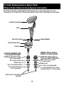
1
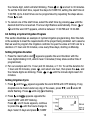
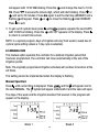
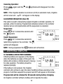
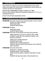
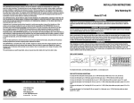
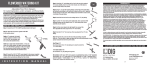
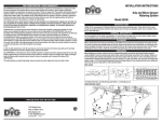
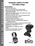
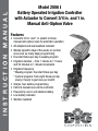
instruction manual
Model 2006 I
Battery Operated Irrigation Controller
with Actuator to Convert 3/4 in. and 1 in.
Manual Anti-Siphon Valve
Features
• Converts 3/4 in. and 1 in. plastic or brass
manual anti-siphon valve to automatic operation
• All adapters and seat washers included
• Weekly (specific days of the week) or cyclical
(once ever so many days) programming
• Four start times per day in weekly program
• Irrigation duration – from 1 minute to 11 hours
and 59 minutes in 1 minute increments
• Irrigation frequency
° Weekly program: four start times per day
° Cyclical program: from eight times per day
(every 3 hours) to just once per month
• Simple, four-button programming
• Perform manual runs via the controller
• Powered by one 9-volt alkaline battery
• Low battery indicator
• Weather resistant
Table of contents
INTRODUCTION… …………………………………………………………… 3
1. Box contents…………………………………………………………… 3
2. Parts identification……………………………………………………… 3
3. Battery installation and removal… ……………………………………… 4
3.1 Battery installation… ……………………………………………… 4
3.2 Battery removal… ………………………………………………… 4
4. Choosing the proper adapter… ………………………………………… 4
5. Collar assembly………………………………………………………… 6
6. Adapter/seat washer installation………………………………………… 7
7. Installation of valve adapter with controller… …………………………… 8
8. Programming method…………………………………………………… 9
8.1 Programming… …………………………………………………… 9
8.2 Setting current time & day of the week……………………………… 10
8.3 Programming a weekly irrigation schedule………………………… 10
8.4 Setting a cyclical irrigation program… ……………………………… 12
8.5 Manual run………………………………………………………… 13
8.6 Suspend irrigation (rain off)… ……………………………………… 14
9. Additional displays……………………………………………………… 14
9.1 Blinking low battery warning… …………………………………… 14
9.2 Missing definition in irrigation program……………………………… 15
9.3 Programming error… ……………………………………………… 15
10. Helpful hints and additional information… ……………………………… 15
11. Maintenance…………………………………………………………… 16
12. Troubleshooting and repairs… ………………………………………… 16
Parts identification / Replacement parts ordering information… ……… 18
Warranty… …………………………………………………………… 19
Technical assistance… ………………………………………………… 20
2
introduction
Thank you for purchasing DIG’s battery operated controller to convert a 3/4 in. or
1 in. plastic or brass manual anti-siphon valve to automatic operation. Please take
the time to read through the enclosed instructions before installation. If you have
any questions, please call our customer service line at 1-800-344-2281.
The battery operated controller model 2006I converts a 3/4 in. or 1 in. plastic
or brass manual anti-siphon valve to automatic operation. The Controller has a
wide range of features offering a reliable cost effective solution for residential and
commercial uses. This instruction manual is designed to help set up and operate
the battery operated controller. After reading the manual and getting familiarized
with the basic functionality of the device, use the manual as a reference for less
common tasks in the future.
1. box contents
• Controller with 24 in. cable connected to the 3/4 in. actuator
• 3/4 in. and 1 in. adapters for Champion, Orbit and Rain Bird valves
• 3/4 in. and 1 in. seat washers for Champion, Orbit and Rain Bird valves
• Owner’s Manual
2. parts identification
1) Top cover
q
2) Controller
3) 6 buttons for programming with LCD display
4) Mounting collar
5) 24 in. extension wire from the controller to the solenoid
u
6) 9V DC solenoid
7) Flow control knob
i
8) External Bleed Screw
o
9) Actuator
a
10) Adapter
s
11) Seat washer assembly
3
IRRIGATION PRODUCTS
w
e
r
t
y
3. BATTERY INSTALLATION AND REMOVAL
3.1 Battery Installation
1.Holding the upper section of the controller above
the mechanical handle, use a firm upward twist
to release the controller from the skirt.
2.Invert the controller and use firm pressure to lift
the battery compartment cover (1).
3.First, align the + (positive) battery terminal with
the + contact in the battery compartment, then
insert the bottom end of the 9-volt alkaline battery (2) and
press on the top end (3) to ensure the battery is firmly in place.
3.2 Battery Removal
1.Remove the battery compartment cover (4).
2. First, lift the lower end of the battery (5).
If necessary, use the flat end of a small
screwdriver.
• Removing the battery from the top end may
damage the connections.
• Use alkaline batteries only.
• Replace battery compartment cover in its proper place, ensuring a triangle is formed on the underside of the controller.
NOTE: Battery polarity is marked in the battery compartment.
4. choosing the proper adapter
The 2006i irrigation controller comes factory assembled to fit 3/4 in. Champion
and Orbit manual brass valves. Included in the package are adapters to fit 1 in.
Champion, Orbit manual brass valves, 3/4 in. and 1 in. RAIN BIRD and RAINJET
manual plastic valves.
NOTE: Please select proper adapter.
4
4. choosing the proper adapter...continued
Actuator stem
As factory assembled for
3/4 in. brass valves only
Assembly for all plastic
valves & 1 in. brass valves
Champion, Rain bird & Orbit
3/4 in. brass adapter
3/4 in. brass washer
Retainer clip
3/4 in. seat washer body
Champion & Orbit adapter for 1
in. brass & Rainjet, Rain bird &
OrbiT 3/4 in. & 1 in. plastic
1 in. brass washer
Retainer clip
1 in. 3/4 in. seat washer body
1 in. Seat washer for 3/4 in.
and 1 in. plastic valves & 1 in.
brass valves
Main screw for seat washer
assembly
3/4 in. seat washer for
3/4 in. brass valve
Main screw for seat washer
assembly
Seat washer assemblies
5
5. COLLAR ASSEMBLY
1.Hold the collar by the round shaped sides
(see Figures 1 and 2).
2.Invert the controller assembly and use firm
pressure to insert the lower side of the collar
into the controller’s center nub (see Figure 3).
3. Lower the collar and snap it to the groove at
the lower part of the Controller assembly (see
Figure 4).
4.Insert the controller assembly with the collar
on the to of the solenoid and make sure the
wire fits through the larger slot (see Figure 5).
Figure 1
Figure 2
Figure 3
IRRIGATION PRODUCTS
Figure 5
Figure 4
6
6. adapter/seat washer installation
The actuator is factory setup to fit 3/4 in.
brass manual anti-siphon valves. To install the
actuator on 1 in. brass anti-siphon valves and
all other manual plastic valves, the 3/4 in. seat
washer and adapters must be removed and
replaced with the 1 in. adapter and seat washer
Figure A
which are included in this box.
1.Turn the actuator so that the seat washer and
the 3/4 in. threaded adapter facing up.
2. Using pliers, remove the seat washer screw by
turning counter clockwise and pull off the 3/4
in. seat washer assembly (see Figure A).
3.Push the 3/4 in. threaded adapter down (see
Figure B
Figure B).
4.Place your thumb on one side of the retainer
clip and with a pair of pliers grip the other side
of the retainer clip and pull outwards then
upwards, removing it from the base of the
3/4 in. adapter threaded. Next, pull off the
3/4 in. threaded adapter from the actuator stem Figure C
(see Figure C).
5.Install the 1 in. threaded adapter by pushing
it onto the actuator stem and making sure the
notch on the adapter lines up with the notch on
the stem of the actuator (see Figure D).
6.Spread the retainer clip with your thumbs and
push the retainer into the adapter until it clicks
Figure D
(see Figure E).
7.Install the 1 in. seat washer assembly making
sure the plastic is on top and the rubber is
facing down. Insert the seat washer screw into
the bottom of the actuator stem and tighten
with pliers by turning clockwise (see Figure E).
Figure E
NOTE: Do not over-tighten.
7
7. installation of valve adapter with Controller
Operating pressure: 25-125 PSI
Flow control knob
A
B
C
Manual Stem
Valve
Body
Anti-Siphon Cap
1. Shut off main water supply.
2. Remove the manual stem from the existing valve and temporarily remove the
anti-siphon cap (see A).
3. Replace any existing worn washers with the new ones provided.
4. Install the actuator with the controller into the manual anti-siphon valve body by
turning actuator clockwise. Tighten firmly, but do not over tighten (see B).
5. Turn on main water supply.
6. Program the controller, or if the controller is programmed, make sure the
current time, a duration, days of operation and start time are displayed.
7. Press
to test the controller. A click will be heard indicating the valve is
open ( The and symbols will appear on the lower right side).
8. Turn flow control knob clockwise to decrease flow, counter-clockwise to
increase flow.
8
9. Push
and verify that the valve closes. (The manual
disappear.)
and
symbols will
8. Irrigation PROGRAMMING
The controller is programmed with the aid of 4 buttons.
Programming mode: Use to accept and/or select the desired programming mode.
Data Increment (increase): Use to raise the value of the selected program feature
(e.g. increase the minute and hour).
Data Decrement (decrease): Use to lower the value of the selected program feature
(e.g. decrease the minute and hour).
Flash button: used to select the parameter to be changed (e.g. hour, minute,
etc.) To implement the change, the selected parameter must be flashing.
If no changes are implemented, the Controller display will always revert to
the main screen (clock).
NOTE: Display digits will stop flashing after 10 seconds. If the last parameter
stops flashing before programming is complete press to continue the
process.
NOTE: After programming the controller, test the controller via the manual
program button (see section 8.5).
8.1 PROGRAMMING METHOD
There are two options for setting irrigation frequency: Weekly Schedule Mode (see
8.3) where watering occurs on specific days of the week (up to four start times per
day in this mode) or Cyclical Mode (see 8.4), where watering occurs at a pre-set
interval (one start time per day in this mode). You must select one mode or the
other, not both.
8.2 Setting Current Time & Day of the Week
To enable the irrigation controller to operate the irrigation system at the required
times, the current time and day of the week must be set as shown:
Setting the Clock
To enable the controller to operate the irrigation system at the desired intervals or
times, the current time and day of the week must be set as shown:
9
1. Press
until the main screen appears.
and the hour digits start blinking. Set the current hour with the aid of
2. Press
and .
(Note the AM or PM designation)
and the minute digits start blinking. Set the current minute with the
3. Press
aid of
and .
* For 24-hour clock display (military time): Once the hour/minute digits are not
blinking or stop blinking, press concurrently
and
and the time will switch
from AM/PM to military time. Pressing these buttons simultaneously again will
revert the display back to AM/PM hour display.
Setting the Current Day of the Week
After the current time has been entered set the
days of the week to irrigate.
1. Press until a blinking appears at the top
of the display.
2. Set the water droplet on the current day of
the week by pressing or . Press to review
8.3 Programming a Weekly Irrigation Schedule (Specific days of
the week)
This section illustrates an example of weekly irrigation programming. Simply
alter the data in the example and change the program to meet your irrigation
requirements. Let’s assume that we want to program the irrigation controller to
water three times a day at 8:00 AM, 1:30 PM and 7:00 PM for 10 minutes each
time on Tuesdays and Fridays, only.
First, program the watering duration
1.Press until appears opposite the word
DURATION with the hour digits blinking
0:05, which means 5 minutes (It may show
another time if programmed).
2.Per our example, set it to 10 minutes, or
10
0:10. To set the duration for 10 minutes, press
to skip the hour digits,
the minute digit is blinking. Press
or
until the minute digit reaches 10
minutes.
Second, schedule the days of the week
1.Press the main button and a Icon appears opposite the word DAYS with OFF
blinking.
2.Press
and a flashing appears under
Monday in the upper section of the display.
Using
position the flashing marker
under Tuesday. Press
and the under
Tuesday will stop flashing, become solid,
and a new drop appears flashing under
Wednesday. Press
twice more until the flashing reaches Friday. Press
to select. The under Friday will stop flashing and Friday is selected as a
day to irrigate and at the same time a will
appear blinking under Saturday.
3.Press and the Icon opposite the word
DAYS and START I on the lower side of the
display appears with OFF blinking.
Last, program irrigation start time
The
icon opposite the word DAYS and
START I with OFF is blinking from the previous
steps.
1. To set the three starts times per our
example, begin by pressing ; the word OFF
changes to 12:00 AM with the digit 12 blinking.
Press , and change the hour to 8:00 AM (note the AM/PM indicator).
2.To set the second start time, press and START II will appear with OFF
blinking. Press , and OFF will change to 12:00 AM with the hour digit 12
blinking. Press
again and change the hour to 1:00 PM. Press
to access
11
the minute digit, which will start blinking. Press
or
and set to 30 minutes.
To set the third start time, repeat the steps for START III, setting the start time at
7:00 PM. Up to 4 start times can be programmed by repeating the steps above.
Press to exit.
until the
3.To cancel one of the start times, select the start time by pressing
desired start time is reached. The hour digit flashes automatically. Press or until the word OFF appears, which is between 11:00 PM and 12:00 AM.
8.4 Setting a Cyclical Irrigation Program
This section illustrates an example of cyclical irrigation programming. Alter the data
in the example to meet the requirements of the project being installed. Let’s assume
that we want to program the irrigation controller to open the valve at 10:45 am for a
duration of 1 hour and 30 minutes, once every three days, starting on Monday.
Setting Irrigation Duration
1. Press the main button and appears opposite the word Duration with the
hour digits blinking 0:05, which mean 5 minutes (It may show another time if
programmed).
2.Per our example set it to 1 hour and 30 minutes, or 1:30. To set the duration for
1 hour and 30 minutes, press
, and select one hour, then press the
, and
the minute digits are blinking. Press
or
until the minute digits reach 30
minutes.
Setting Irrigation Cycle
1.Press and the
appears opposite the word DAYS with OFF blinking. If any
droplets can be found under any day of the week, press
, and under M
starts flashing. Press
until only is flashing.
appears opposite the
2.Press and
word START with OFF blinking.
Press , and 3 hours appears, continue
to press the
until the hours change to
days. Select 3 days and press ; START
12
will appear with 12:00 AM blinking. Press the
and change the hour to 10:00
AM. Press
to access the minute digit, which will start blinking. Press
or
and set to 30 minutes. Press
again to set the start day (MONDAY) and a
flashing will appear. Press
or
to move the flashing under MONDAY.
Press to exit.
3.To get out of cyclical mode press
with 3 DAYS is blinking. Press the
to return to current time screen.
until
appears opposite the word DAYS
until OFF appears on the display. Press
NOTE: In a cyclical program, days of irrigation will vary from week to week due of
cyclical cycle setting (unless a 7 day cycle is selected).
8.5 manual run
This manual option operates the controller for a defined irrigation period that
has been programmed. The controller will close automatically at the end of the
irrigation period.
Note: The originally programmed irrigation schedule will continue to function at the
set times.
This setting cannot be implemented when the display is flashing.
Manual Operation:
and the will appear next to
Press until current time is displayed. Press
the word MANUAL. The symbol will appear underneath it and the valve will open.
The days of the week and the irrigation duration that was set in the program will
appear on the display.
Week 1
13
Week 2
Canceling Operation:
Press
again and the
display.
and
symbols will disappear from the
NOTE: If the irrigation duration is set at zero (0:00) in automatic mode, irrigation
will not occur and will appear on the display.
8.6 suspend irrigation (Rain Off)
This option is used to temporarily suspend irrigation controller operation, for
example, while it is raining. Programmed schedules remain in the controller
memory but are not implemented until the suspension is cancelled.
Suspension:
Press
for 5 consecutive seconds until
the
appears.
Cancel Suspension:
for 5 consecutive seconds to
Press
restart the programs in the controller. The
symbol will disappear.
NOTE: During suspension the
button will not function.
9. additional displays
9.1 Blinking Low Battery Warning
A flashing battery icon appears on the display
when the batteries are weak. At this point, the
battery still contains a limited amount of energy
for valve operation. The battery should be
replaced promptly.
If the battery is not replaced, the irrigation
controller will continue to open the valve 8 additional times according to the
program. It will then suspend the program and OFF will appear on the screen.
Program data will be retained for 30 seconds during battery changing.
An irrigation controller without a battery will not operate the valve.
14
9.2 Missing Definition in Irrigation Program
will appear if irrigation duration is set at
zero (0:00) (see Note: in Section 8.5). In this
case, the valve cannot be opened for automatic
or manual operation via the controller.
9.3 Programming Error
In the cyclical program (see section 8.4) if the
irrigation duration programmed is equal to or
longer than the irrigation cycle, the word
will appear.
To cancel the error, press
or
to increase
the irrigation cycle.
10. HELPFUL HINTS AND ADDITIONAL INFORMATION
1. Manual runs can be initiated at any time when current time is displayed by
pressing the manual button once. The valve will operate one time for the length
of time programmed and then proceed back to the normal programming.
2. All DIG controllers can be programmed first and installed at a later date. No
water pressure is required.
3. Always make sure that the battery compartment is clean and dry. If water should
get on the battery, immediately remove and wipe clean.
4. We strongly recommend brand name alkaline batteries. Rechargeable batteries
are not recommended.
5 Under normal usage, batteries (alkaline) will last for a minimum of 1 year,
maximum of 2 years.
6. It is good operating practice to replace old batteries with new ones at the start of
the irrigation season.
7. The valve actuator can be opened and closed manually by turning the external
bleed screw to the left and right.
15
11. MAINTENANCE
If the controller is not going to be use for an extended period of time, remove
batteries and replace cover securely. After an extended time without batteries the
controller will need to be reprogrammed.
KEEP BATTERY COMPARTMENT SECURELY CLOSED AT ALL TIMES.
Remove controller and store indoors when temperature drops below 32° F (0° C) for a
prolonged period of time.
Be sure to shut off water supply before removal.
12. TROUBLESHOOTING AND REPAIRS
PROBLEM:Valve does not open during automatic operation or during “manual”
operation via irrigation controller.
CAUSE: Weak battery.
SOLUTION: Replace battery.
PROBLEM:No display.
CAUSE: Weak battery.
SOLUTION: Replace battery.
PROBLEM:Valve does not close despite clicks heard during activation.
CAUSE: Outlet flow may be too low (minimum flow .5 GPM).
SOLUTION: Increase flow rate by adding drip emitters, micro
sprinklers or sprinklers.
CAUSE: Valve is installed backwards.
SOLUTION: Reverse valve.
CAUSE: Plunger is installed upside down.
SOLUTION: Unscrew solenoid. Remove plunger and re-install with
rubber tip exposed.
PROBLEM:Valve does not fully close.
CAUSE: Worn or damaged seat washer
SOLUTION: Replace or invert seat washer
CAUSE: Wrong seat washer is installed or seat washer is upside
down.
SOLUTION: Use larger seat washer or flip seat washer over.
16
PROBLEM:Water discharges from anti-siphon cap.
CAUSE: Heads are above valve.
SOLUTION: Raise valve or use angle valve.
CAUSE: Anti-siphon float is missing or damaged.
SOLUTION: Check or replace float.
PROBLEM:Valve does not close completely.
CAUSE: Static pressure is above 125 PSI.
SOLUTION: Install a mainline pressure regulator.
PROBLEM:Valve does not open.
CAUSE: Actuator ports are blocked.
SOLUTION: Shut off water supply, remove solenoid and solenoid
adapter, open water supply momentarily and flush out solenoid
ports. Reinstall solenoid. Open water supply and test manually.
17
To Order Replacement or Spare Parts:
Please Order Online at www.digcorp.com/rparts
We at DIG Corporation understand that most dealers do not carry spare parts. For your
convenience, if you need one of these parts, please order online at www.digcorp.com/rparts.
Controller & Solenoid
Collar
Solenoid Adapter
Flow control knob
External bleed screw
Actuator
As factory assembled for
3/4 in. brass valves only
Assembly for all plastic
valves & 1 in. brass valves
Champion, Rain bird & Orbit
3/4 in. brass adapter
3/4 in. brass washer
Retainer clip
3/4 in. seat washer body
Champion & Orbit adapter for
1 in. brass & Rainjet, Rain bird &
OrbiT 3/4 in. & 1 in. plastic
1 in. brass washer
Retainer clip
1 in. 3/4 in. seat washer body
1 in. Seat washer for 3/4 in. and 1
in. plastic valves & 1 in. brass valves
3/4 in. seat washer for
3/4 in. brass valve
Main screw for seat washer
assembly
18
WARRANTY
DIG CORPORATION warrants these products to be free from defects in material and
workmanship under normal use for a period of three years from date of purchase. This
warranty does not cover damage resulting from accident, misuse, neglect, modification or
improper installation. This warranty shall extend only to the original purchaser of the product
for use by the purchaser. This warranty shall not cover batteries or any malfunction of the
product due to battery failure. The obligation of DIG CORPORATION under this warranty is
limited to repairing or replacing at its factory this product which shall be returned to the
factory within three years after the original purchase and which on examination is found to
contain defects in material and workmanship.
DIG CORPORATION SHALL IN NO EVENT BE LIABLE FOR ANY INCIDENTAL OR
CONSEQUENTIAL DAMAGES OF ANY KIND; THE SOLE OBLIGATION OF DIG BEING LIMITED TO
REPAIR OR REPLACEMENT OF DEFECTIVE PRODUCTS. SOME STATES DO NOT ALLOW THE
EXCLUSION OR LIMITATION OF INCIDENTAL OR CONSEQUENTIAL DAMAGES, SO THE ABOVE
LIMITATION OR EXCLUSION MAY NOT APPLY TO YOU.
Unattended use for prolonged periods without inspection to verify proper operation is
beyond the intended use of this product, and any damage resulting from such use shall not
be the responsibility of DIG CORPORATION. There are no warranties which extend beyond the
description on the face hereof. In the case of purchase of the product for use other than for
rrigation purposes DIG CORPORATION hereby disclaims any implied warranties including any
warranties of merchantability and fitness for a particular purpose. In the case of the purchase
of the product for personal, family or household purposes, DIG CORPORATION disclaims
any such warranties to the extent permitted by law. To the extent that any such disclaimer
or implied warranties shall be ineffectual, then any implied warranties shall be limited in
duration to a period of three years from the date of the original purchase for use by the
purchaser. Some states do not allow limitation on how long an implied warranty lasts, so the
above limitation may not apply to you.
In order to obtain performance under this warranty, the unit must be returned to the
factory, along with proof of purchase indicating original date of purchase, shipping prepaid,
addressed as follows:
DIG CORPORATION, 1210 Activity Drive, Vista, CA 92081-8510. Repaired or replaced
units will be shipped prepaid to the name and address supplied with the unit returned under
warranty. Allow four weeks for repairs and shipping time. Repair of damaged units not
otherwise within warranty may be refused or done at a reasonable cost or charge at the
option of DIG CORPORATION.
This warranty gives you specific legal rights, and you may also have other rights which
vary from state to state.
19
TECHNICAL ASSISTANCE
Should you encounter any problem(s) with this product or if you do not understand its many
features, please refer to this instruction manual first. If further assistance is required, DIG
offers the following customer support:
Technical Service USA
• DIG’s Technical Service Team is available to answer questions in English and Spanish
from 8:00 AM to 5:00 PM (PST) Monday-Friday (except holidays) at 800-344-2281.
• Questions in English and Spanish can be e-mailed to [email protected] or faxed to
760-727-0282.
• Specification documents and manuals are available for downloading in English and
Spanish at www.digcorp.com
Website:
www.digcorp.com
e-mail: [email protected]
E
051811 DIG CORP 26-018
Printed in the USA
DIG is a Registered Service Mark of DIG Corp.
1210 Activity Drive
Vista, CA 92081-8510, USA
20