1
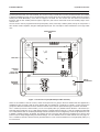
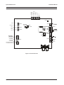
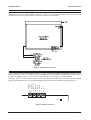
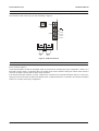
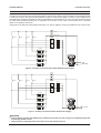
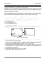
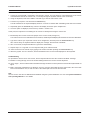
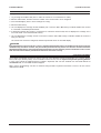
Pyramid DC Receiver Installation Manual Please read this manual before installing your receiver Pyramid DC Receiver Installation Manual IMPORTANT The first few pages of these instructions contain important information on safety and product conformity. Please read, and ensure that you understand this information before continuing. Page 2 Installation Manual Pyramid DC Receiver CONTENTS Product Safety ........................................................................................................................................................................................... 4 Electromagnetic Compatibility (EMC) .................................................................................................................................................. 4 Manufacturers Declaration of Conformance .................................................................................................................................... 4 Unpacking ................................................................................................................................................................................................... 4 Barcoding ................................................................................................................................................................................................... 4 The DC Receiver .......................................................................................................................................................................................... 5 PCB Layout ................................................................................................................................................................................................... 6 PCB Power Connections .............................................................................................................................................................................. 7 Connecting the Preset Feedback Potentiometers ........................................................................................................................................ 7 Connecting the Lens Drive Outputs ............................................................................................................................................................. 8 Anti-Tamper Connections ............................................................................................................................................................................. 8 Connecting Auxiliaries .................................................................................................................................................................................. 9 Connecting the Pan/Tilt Head ..................................................................................................................................................................... 10 Video Connections ..................................................................................................................................................................................... 10 Fitting Network Cards ................................................................................................................................................................................. 11 PY-COM Network Cards ............................................................................................................................................................................ 12 Network Connections ................................................................................................................................................................................. 13 Power Supply Connections ....................................................................................................................................................................... 13 Addressing a Receiver with the Pyramid 2 Keyboard .............................................................................................................................. 14 Addressing a Receiver with the Mk1 Keyboard ....................................................................................................................................... 15 Setting Receiver Configuration with the Pyramid 2 Keyboard .................................................................................................................. 16 Setting Receiver Configuration with the Mk1 Keyboard ........................................................................................................................... 17 Receiver Programming ............................................................................................................................................................................... 17 Testing ........................................................................................................................................................................................................ 18 Replacing the Lid ........................................................................................................................................................................................ 18 Changing the Fuse ..................................................................................................................................................................................... 18 Specifications ............................................................................................................................................................................................. 19 Page 3 Pyramid DC Receiver Installation Manual PRODUCT SAFETY WARNING Please follow these instructions as you install the equipment and keep them for future use. Installation is only to be carried out by competent, qualified and experienced personnel in accordance with the country of installations National Wiring Regulations. Failure to do so can result in injury or death by electric shock. Use a class 2 isolated power supply for the 12V DC. The module is susceptible to damage from Electrostatic Discharge (ESD). Take normal ESD precautions when handling your network card. ESD prevention kits are available from most electronics distributors. Do not exceed the voltage and temperature limits given in the specification. Switch off the power before fitting a network card. If you have any problems, contact Baxall Limited. ELECTROMAGNETIC COMPATIBILITY (EMC) CAUTION This is a Class A product. In a domestic environment this product may cause radio interference in which case the user may be required to take adequate measures. This product is intended for use in general purpose CCTV applications in a residential, commercial or light industrial EMC environment. Refer to Baxall Limited before using the product in medical and/or intrinsically safe applications or in an industrial EMC environment. If you are using the PCB version of this product in a way other than correctly installed in the Pyramid system weatherproof boxes, then it is your responsibility to meet EMC requirements. The product must be installed in accordance with good installation practice for EMC to enable the product to function as intended and to prevent EMC problems. Contact Baxall Technical Support to obtain a specification defining the acceptable levels of product degradation with regard to EMC immunity. MANUFACTURERS DECLARATION OF CONFORMANCE CAUTION The declaration of conformance applies only to the boxed version and PCBs which are correctly installed in our Pyramid system weatherproof box. The manufacturer declares that the equipment supplied with this manual is compliant with the essential protection requirements of the EMC directive 89/336 and the Low Voltage Directive LVD 73/23 EEC. Conforming to the requirements of standards EN55022 for emissions, IEC801 parts 2, 3 and 4 for immunity and EN60950 for Electrical Equipment safety. UNPACKING Keep your packaging for use if your DC receiver is stored for an extended period or needs to be returned for any reason. The packaging should contain: A DC Receiver An A4 Module Description Sheet (for installation details) These instructions Two identical barcodes Check the product code on the serial number label. If you have an incorrect item or it is damaged then inform the suppliers and carriers immediately. If this is the case, do not attempt to use the equipment. BARCODING The DC receiver is supplied with two identical barcodes. Remove one and affix it to the module description sheet, remove the other and affix it to the module. The barcode gives the unique 48-bit neuron ID to the module. This neuron ID is also stored inside the module and will be transmitted onto the network whenever the PCB service pin is pressed. Before installation, make a careful note on your module description sheet of all your installation details and the proposed location of the module. Then during subsequent installation using the Windows installation tool the neuron ID can be entered. We recommend that during a system installation you store the module description sheets in a ring-bound file, and keep them for reference after the installation is complete. Page 4 Installation Manual Pyramid DC Receiver THE DC RECEIVER The Pyramid DC Receiver is a variable speed pan and tilt control receiver that can be connected to any camera within the Pyramid system that has a DC Pan/Tilt head. The receiver is easy to install, and a service pin and test button are included to aid the installation process. Once it has been fitted, the receiver drives the Pan/Tilt head at variable speed by using the PWM (Pulse Width Modulation) of the 24V DC supply to the head. The DC receiver can also drive zoom and focus functions, and the four auxiliary functions (wipers, lights etc.) that can be connected via the four auxiliary relays on the receiver PCB. The DC receiver can be programmed remotely with privacy zones, limit stops, random patrols, and up to 128 presets. It also contains a video amplifier, with gain and high-frequency lift. This can improve video transmission over longer cable runs. WEATHERPROOF BOX MAIN PCB FACTORY FITTED 24V DC PSU (UNDER PCB) METAL BASEPLATE EXTERNAL TERMINAL BLOCK Figure 1 - DC Receiver Layout (Weatherproof Box Variants) There are six variants of the DC receiver, which can be split into two groupsthe three variants that are supplied in a weatherproof box (PY-DCW-) and the three variants that are supplied as a PCB only (PY-DCB-). In each of these two groups, the difference between the three variants is based on the network speed and the type of network card fitted. The -L variants (PY-DCW-L and PY-DCB-L) run on a low speed (9.8k b.p.s.) RS485 network while the -HR variants (PYDCW-HR and PY-DCB-HR) run on a high speed (78k b.p.s.) RS485 network. Both the -L and -HR variants are fitted with a PY-COM network carda combined personality network card which can be configured by means of dip switches for use in RS485 or RS422 networks. By default, the switches are set so that the card operates in RS485 protocol, but the card protocol can be easily changed using the switch settings. For more details on the PY-COM network card, see page 12. The -H variants (PY-DCW-H and PY-DCB-H) are fitted with a PY-FTT network card and run on a high speed (78k b.p.s.) FTT10 network. Page 5 Pyramid DC Receiver Installation Manual PCB LAYOUT 5V + 5V + TILT FB PAN FB FOCUS FB ZOOM FB GROUND GROUND Shown below are the locations of the connectors, switches and LEDs on the DC receiver PCB. CON2 LED1 1 LIVE CON9 3 NEUTRAL AUX 1 CON11 AUX 2 AUX 3 SERVICE PIN LED CON1 TEST BUTTON CON19 SERVICE PIN CON10 AUX 4 + NETWORK NETWORK CON6 ANTI-TAMPER SWITCH 8 PAN DRIVE 7 TILT RETURN 6 TILT DRIVE 5 PAN BRAKE 4 TILT BRAKE 3 PAN BRAKE RETURN 2 TILT BRAKE RETURN 1 IRIS + CON3 CON13 ZOOM ZOOM + VIDEO IN Figure 2 - DC Receiver PCB Page 6 FOCUS FOCUS + VIDEO OUT Installation Manual Pyramid DC Receiver PCB POWER CONNECTIONS A +24V DC, 65W class 2 power supply unit is connected to the PCB through CON1. The necessary connections have already been made on the boxed variants (see Figure 3), so there is no need for the installer to make any further power connections to the PCB. On PCB versions, connect the +24V DC as shown below. - + LIVE NEUTRAL Figure 3 - PCB Power Connections CONNECTING THE PRESET FEEDBACK POTENTIOMETERS If you are using a preset Pan/Tilt head and lens, then CON2 provides the supplies and feedback connections for the potentiometer wiper circuits. The direction of the DC feedback circuit is automatically calculated when the test routine is invoked (see Testing on page 18). This means it is not necessary to wire the pots in a specific direction. 5V + 5V + TILT FB PAN FB FOCUS FB ZOOM FB GROUND GROUND Referring to Figure 4, connect CON2 to the preset pots on the Pan/Tilt head and the lens. Connect any unused feedback inputs to ground. Make a note on your module description sheet of the preset connections and the type of lens. CON2 LED1 Figure 4 - CON2 Connections Page 7 Pyramid DC Receiver Installation Manual CONNECTING THE LENS DRIVE OUTPUTS CON3 provides the lens drive outputs for focus, iris and zoom. The drive voltage is +12V DC at up to 100 mA. Refer to your lens instructions and connect up your lens according to Figure 5. CON6 ANTI-TAMPER SWITCH IRIS + CON3 FOCUS FOCUS + ZOOM ZOOM + VIDEO IN VIDEO OUT Figure 5 - CON3 Connections ANTI-TAMPER CONNECTIONS CON6 is used as an input for an external anti-tamper switch. It is connected in parallel with the built in anti-tamper switch that is marked in Figure 2. On the boxed variants, the built in anti-tamper switch is connected in a normally open (N/O) configuration. However, it is fitted with a spring which is compressed when the module lid is closed, and thus closing the contact. When the lid is removed, the input is opened and the alarm will be activated. If the built in anti-tamper switch is not used, CON6 can be connected to an external anti-tamper switch. To do this, the spring must be removed from the built in anti-tamper switch. CON6 should then be connected to the external anti-tamper switch in a normally closed (N/C) configuration. Page 8 Installation Manual Pyramid DC Receiver CONNECTING AUXILIARIES Up to four auxiliaries can be connected and powered by the DC receiver via CON9, CON10 and CON11. Auxiliaries are connected to CON10 and CON11, and a power supply is connected to CON9. The power supply is then switched through to CON10 and CON11, thus powering the auxiliaries. A 240V AC mains power supply or a 24V AC power supply can be used (although it should be noted that no auxiliary should draw over 2A at 240V AC). In both cases, the connection should be made via the external terminal block, as it provides an in-line fuse for the circuit. It also provides more connection space for the auxiliary return wires. Using Figure 6 for 240V AC mains supplies and Figure 7 for 24V AC supplies, connect the auxiliaries to the receiver PCB. CON 9 1 LIVE 3 NEUTRAL AUX 4 AUX 3 AUX 2 AUX 1 CON 10 AUX 1 AUX 2 AUX 3 AUX 4 Snubber CON 11 Snubber Snubber Snubber LIVE NEUTRAL Figure 6 - Auxiliary Connections with a 240V AC Mains Power Supply CON 9 1 3 AUX 4 AUX 3 AUX 2 AUX 1 CON 10 AUX 1 AUX 2 AUX 3 AUX 4 Snubber CON 11 Snubber Snubber Snubber 24 V A.C. Figure 7 - Auxiliary Connections with a 24V AC Power Supply CAUTION Connect lamps of greater than 300W using a separate relay as they can draw a surge current when they fail. This may damage the DC receiver. Always provide a separately fused mains spur for use with auxiliary devices. Page 9 Pyramid DC Receiver Installation Manual CONNECTING THE PAN/TILT HEAD CON13 provides the power output connections for the Pan/Tilt head. The connections that must be made depend on the type of Pan/Tilt head used (e.g., 4-wire, 6-wire, 8-wire). When using an 8-wire Pan/Tilt head, all eight terminals on CON13 will be used (see Figure 8). When using 6-wire Pan/ Tilt heads, only the top six terminals on CON13 will be used, with Pan Brake Return (No.2) and Tilt Brake Return (No.1) left unused. Similarly with a 4-wire Pan/Tilt head, only the top four terminals will be used. If necessary, a 7-wire System 7000 Pan/Tilt head can also be used with the DC receiver, but the Pan/Tilt head will require manufacturer modification beforehand. Contact Baxall Technical Support for more details. 8 PAN DRIVE 7 TILT RETURN 6 TILT DRIVE 5 PAN BRAKE 4 TILT BRAKE 3 PAN BRAKE RETURN 2 TILT BRAKE RETURN 1 CON13 Figure 8 - CON13 Connections (8-wire P/T head) CAUTION The Pan/Tilt head must not draw more than 1A per drive output and 0.25A per brake output or it will damage the DC receiver. VIDEO CONNECTIONS All video must be connected to the receiver PCB via 75 ohm BNC connectors and video coaxial cable. Referring to Figure 2, connect the video from your camera to VIDEO IN and connect VIDEO OUT to the matrix. Your DC receiver has an on-board video amplifier with gain and lift. Adjustment of gain and lift is done remotely, using a Pyramid keyboard. For more details on adjusting gain and lift levels, consult the Pyramid 2 Keyboard Operating Manual. Page 10 Installation Manual Pyramid DC Receiver FITTING NETWORK CARDS To connect the DC receiver to the network, it is first necessary to ensure that the correct Pyramid network card is fitted to the PCB. The cards that can be used are as follows: PY-COM Combined network card. Can be configured for use in RS485 and RS422 networks. Automatic baud-rate selection between low and high speeds (9.8k b.p.s. or 78k b.p.s.). PY-FTT Compatible with FTT10 (Flexible Topology) 2-wire bus-connected, half duplex. High speed only. PY-422 Compatible with RS422, 4-wire point-to-point, full duplex. Available in low and high speed variants. PY-485 Compatible with RS485, 2-wire bus-connected, half duplex. Available in low and high speed variants. PY-FI7 and PY-FI9 Compatible with dual, multi-mode fibre optic point-to-point connections. PY-FI7 operates at 78k b.p.s., PY-FI9 operates at 9.8k b.p.s. If the correct network card is not already fitted, change it using Figure 9 as a guide. CAUTION To avoid damaging the module, switch off the power before fitting the network card. Figure 9 - Fitting a Network Card Once a network card has been fitted, it must be connected to the network through CON19. If the card is a PY-COM, it may also need to be configured via a group of dip switches. See the following sections for more details. Page 11 Pyramid DC Receiver Installation Manual PY-COM NETWORK CARDS If a PY-COM network card is fitted to the DC receiver, it can be configured by means of dip switches for use in both RS485 and RS422 networks. The dip switches for the different network types are shown below: RS485 Mode RS485 networks are 2-wire, bus-connected (also referred to as daisy-chain). In RS485 mode, the dip-switches on the PY-COM will be set differently depending on where the unit is placed on the network. If the unit is the first or last in the network, one network card in the unit will need to be set to provide biasing and termination as required. If the unit is central to the network, all network cards will be set for use in a intermediate module. Set the switches as required and wire the card to the network as shown in Figure 10. It is not necessary to make any connections to the filter board. First Module 8 7 6 5 4 3 2 1 Intermediate Module 8 7 6 5 4 3 2 ON Network Not used 1 Last Module 8 7 6 5 4 ON Network Not used 3 2 1 White represents switch position ON Network Not used Figure 10 - RS485 Switch Settings RS422 Mode RS422 networks use a 4-wire, point-to-point connection methodology. Set the switches as required and wire the card to the network as shown in Figure 11. It is not necessary to make any connections to the filter board. 8 7 6 5 4 3 2 1 White represents switch position ON Input Output Figure 11 - RS422 Switch Settings Page 12 Installation Manual Pyramid DC Receiver NETWORK CONNECTIONS Once the required network card has been fitted to the DC receiver PCB, the unit can be wired to the network. The way in which this is done depends on the network protocol in use, as each of the protocols that can be used with the module (RS485, RS422, FTT10 and Fibre) have different connections and wiring conventions. For RS485, RS422 and FTT10 protocols, the network is wired to CON19. Using Figure 12 as a guide, wire the network to the 5-way connector as follows: FTT10 RS485 Network Ground Not Used RS422 - + Network Ground Not Used - + Out Ground + In Figure 12 - Network Connections If a fibre optic network card (PY-FI7 and PY-FI9) is being used, the network is connected directly to the network card rather than to CON19. For details on how to make these connections, consult the installation instructions that are supplied with the fibre optic network card. POWER SUPPLY CONNECTIONS The boxed variants of the DC receiver include a terminal block mounted on the metal base plate. This external terminal block is used to earth the metal base plate and to connect the factory fitted 24V DC PSU to the mains power supply. LIVE LIVE NEUTRAL NEUTRAL EARTH Figure 13 - External Terminal Block WARNING Ensure that the power is switched off before connecting the mains wires. The module must be earthed. Do not connect additional mains devices to the fused side of the external terminal block. Connect the Live, Earth and Neutral wires from the mains to Live, Earth and Neutral on the non-fused side of the external terminal block. Switch on the mains power and any other power supplies that are being usedthe module now contains live voltages. When the power is switched on, LED1 lights to indicate the polarity of the 24V DC. If the polarity is correct it will light green, and if it is incorrect, it will light red. Page 13 Pyramid DC Receiver Installation Manual ADDRESSING A RECEIVER WITH THE PYRAMID 2 KEYBOARD Each receiver that is connected to the Pyramid system must have a unique address called a network address, and an operator with installer privileges can do this using the Pyramid 2 Keyboard. Configuration of the receiver requires the service button to be pressed on the receiver PCB, and this may be a two man operation if the receiver is located remotely from the keyboard. For this reason, it is easier to address a receiver before it is added to the network, and this can be done using a special mode of the Pyramid keyboard called Self Bind (also known as Fn 100). Self-binding mode is commonly used when configuring telemetry receivers, or when cameras need to be controlled in a system without a CCTV matrix. During the self-binding process, the installer can setup the network address, which includes the node IDthe number that is entered to indicate which device is to be controlled (e.g., Camera receiver number 4). Once the network address has been configured, the receiver can be attached to the network and controlled through the Pyramid matrix. To address a receiver in self-binding mode, follow the steps below: 1. Connect up a Pyramid 2 Keyboard to the telemetry receiver. This can either be connected directly to the receive communications card at the receiver site, or remotely through the Pyramid network in the normal way. 2. Log onto the Pyramid 2 Keyboard using the installer password. The Installer Logon screen is displayed. 3. Press the Function 100 soft-key. The Direct Access screen is displayed. 4. Press the Receiver soft-key. 5. Press the Rx Utilities screen key. 6. Press the Unit Address Type soft-key. The Addressing screen is displayed. 7. Press the Receiver Address soft-key. The keyboard LCD displays a message asking the operator to press the service pin. 3 3 7 12... 12... 6 Operator Rx Utilities Operator Rx Utilities 5 Figure 14 - Addressing a Receiver 8. So that the keyboard can identify the receiver, press its service pin. On the DC receiver, the service pin is located on the PCB as two pins to be shorted (see Figure 2). When the service pin is pressed, the receivers neuron ID is transmitted to all other devices on the Pyramid network. The neuron ID is a unique identifier which is used to establish communication between the receiver and all other devices. Once the receiver has been identified by the network, it can be assigned a node ID. 9. The keyboard LCD displays a message asking the operator to enter the new node ID. The node ID is the visible part of a network address, as it is the number that an operator enters on a keyboard to indicate the device that is to be controlled (e.g., Camera receiver number 3). Use the number keys to enter the node ID. 10. Press the Receiver Address soft-key again to confirm the node ID. The keyboard LCD displays a message confirming the address. Page 14 Installation Manual Pyramid DC Receiver ADDRESSING A RECEIVER WITH THE MK1 KEYBOARD A receiver can also be addressed using the Pyramid Mk1 Keyboard. Follow the steps below: 1. Connect up a Pyramid Mk 1 Keyboard to the telemetry receiver. This can either be connected directly to the receive communications card at the receiver site, or remotely through the Pyramid network in the normal way. 2. Using the keyboard, insert the Installers Card and log on with the PIN number 1892. 3. Press the key sequence 100 and then the Function key. The left hand side of the keyboard display will show Fn 0100 to indicate that self binding mode has been invoked. 4. Repeatedly press the List Down key, until the LCD display shows the option Replace RX. 5. Once this option is displayed, select soft key number 1 marked Yes. At this point, the keyboard is now waiting for the receiver to identify itself using the service PIN. 6. Momentarily short out the service PIN jumper on the receiver PCB (see figure 2). The receiver neuron ID is transmitted onto the network, and the keyboard display will show the text Receiver Identified. 7. Type in the node ID you require this receiver to be configured to, and then press the Camera Select key. After a short delay, the keyboard will then display the message Subnet Node Calculated. 8. After 10 seconds, the keyboard will then log itself out automatically. 9. Repeat steps 1-3 to log back on to the keyboard and go into self-bind mode. 10. Select a camera in the normal way by typing in the node ID and then pressing the Camera Select key. 11. Move the joystick. The PTZ will move, and the standard receiver screen will be displayed on the keyboard. Troubleshooting Q I pressed the service PIN on the receiver, but the keyboard did not show the Receiver Identified message. A No data is coming through, check out the data cabling between the receiver and the keyboard. Q I got to stage 7, but the Subnet Node Calculated message remained on the keyboard screen and the keyboard did not log off. A Data is only being transmitted in one direction. Check to see if the data cable has been connected to the correct side of the communications card, or that one side of the twisted pair has become disconnected. Note The DC receiver can also be addressed and installed using the Pyramid Installation Tool. See the Pyramid Installation Tool Operating Manual for more details. Page 15 Pyramid DC Receiver Installation Manual SETTING RECEIVER CONFIGURATION WITH THE PYRAMID 2 KEYBOARD After a receiver has been addressed, the Pyramid 2 Keyboard can be used to specify the configuration of the receiver remotely via the Pyramid network. To set the configuration of a receiver, follow the steps below: 1. Enter the keyboard menu system. See the Pyramid 2 Keyboard Operating Manual for more details. 2. Select a monitor by entering a number and pressing the Monitor key. 3. Enter the number of the receiver that is to be configured and press the Camera key. 4. Press the Utility Menu screen key. 5. Press the Receiver Utilities soft-key. 6. Press the Rx Config soft-key. The Receiver Configuration screen is displayed. 7. Some Pan/Tilt units are capable of continuous rotation (360O). A small gap can exist in the feedback potentiometer, and this gap is known as the dead band. If a continuous rotation Pan/Tilt head is being used, press the Non-Cont softkey, so that the receiver is configured for a continuous rotation Pan/Tilt unit. The text on the soft-key changes to Cont. The default setting is to leave the soft-key displaying the text Non-Cont (i.e., non-continuous Pan/Tilt head operation). 8. Receivers are supplied with feedback potentiometers enabled. If there are no feedback inputs to the receiver, the manual operation of the Pan/Tilt unit will be affected (e.g., the pan and tilt controls will only operate in one direction), since the feedback inputs are used as a constant check for end stops. If this is the case, disable the feedback potentiometers to correct the problem and enable manual PT operation. To do this, press the F/B soft-key, so that the text changes to No F/B. The default setting is to leave the soft-key displaying the text F/B (i.e., feedback potentiometers enabled). 9. In some cases, zoom lenses have three wire control of zoom and focus functions (i.e., Ground, Zoom +/-, Focus +/-) rather than the usual four wire control. If this is the case, the receiver needs to be configured for the use of a 3-wire lens, so that it carries out the zoom operation first followed by the focus operation on preset recall. To do this, press the 3 Wire Lens soft-key. The default setting is to leave the 3 Wire Lens soft-key off (i.e., in four wire control). 7 8 9 10 Operator VCR / MUX Utility Menu 11 Figure 15 - Receiver Configuration 10. Press the Enter soft-key to confirm the selection and to send the information to the receiver. 11. Press the Utility Menu screen key to leave the Receiver Configuration screen. CAUTION If the Pan/Tilt head connected to the receiver is not fitted with potentiometers, the F/B function must be disabled at step 8. If this is not done, the pan and tilt operations will only work in one direction. If a Pan/Tilt head is fitted with potentiometers, ensure that mechanical limit stops are set, and then press the test button on the receiver PCB. This will ensure that the potentiometer directions are learnt correctly. Page 16 Installation Manual Pyramid DC Receiver SETTING RECEIVER CONFIGURATION WITH THE MK1 KEYBOARD The Pyramid Mk1 Keyboard can also be used to specify the receiver configuration. Follow the steps below: 1. Log on using an installers card (Use Fn 100 if the receiver is not connected to a matrix). 2. Select a valid monitor, and then enter the number of the receiver that is to be configured. 3. Press the List Up key twice to select Change Rx Config. 4. Select the Yes soft key. 5. The LCD displays the message Rx has feedback pots. Press the Yes or No soft key to indicate whether the receiver is connected to feedback potentiometers. 6. To determine whether the receiver is connected to a continuous rotation head, the LCD displays the message Rx is cont rotate head. Press the Yes or No soft key. 7. The LCD displays the message Rx has 3 wire lens Press the Yes or No soft key to indicate whether the receiver is using a 3-wire lens. The receiver has now been configured, and the keyboard will return to the initial display. CAUTION If the Pan/Tilt head connected to the receiver is not fitted with potentiometers, the feedback pots function must be disabled at step 5. If this is not done, the pan and tilt operations will only work in one direction. If a Pan/ Tilt head is fitted with potentiometers, ensure that mechanical limit stops are set, and then press the test button on the receiver PCB. This will ensure that the potentiometer directions are learnt correctly. RECEIVER PROGRAMMING The Pyramid 2 Keyboard can also be used to carry out more advanced receiver programming (e.g., presets, privacy zones, limit stops, random patrols). For more details on how to do this, see the Pyramid 2 Keyboard Operating Manual. A copy of the manual is supplied with the Pyramid 2 Keyboard, and can also obtained from the Baxall website at www.baxall.com, or from Baxall Technical Support. Basic receiver programming can also be achieved using the Mk1 Keyboard. Instructions on how to do this can be obtained from Baxall. Page 17 Pyramid DC Receiver Installation Manual TESTING Once the receiver has been addressed and configured, an on board test procedure can be activated which steps through outputs in the sequence shown in the table below. The test procedure also allows the receiver to detect the feedback polarity for the Pan/Tilt head and lens. The test procedure should be carried out once the Pan/Tilt head has been fitted in position. It runs when the test button is pressed with an appropriate tool (Figure 2). The test takes 57 seconds. WARNING The DC receiver now contains live voltages. Before running the test procedure, fit the Pan/Tilt head in its intended position and ensure that it cannot collide with anything or stretch any cables. Electrical and mechanical limit stops should be set to prevent such events. Electrical limit stops can be set using the Pyramid 2 Keyboardconsult the Pyramid 2 Keyboard Operating Manual for more details. Step Action Time Step Action Time 1 Right and Down 5s 13 Pause 2s 2 Pause 2s 14 Zoom Out 3s 3 Pan Left 3s 15 Zoom In 3s 4 Pause 1s 16 Pause 2s 5 Pan Right 3s 17 Iris Close 3s 6 Pause 2s 18 Iris Open 3s 7 Tilt Up 3s 19 Pause 2s 8 Pause 1s 20 AUX A 2s 9 Tilt Down 3s 21 AUX B 2s 10 Pause 2s 22 AUX C 2s 11 Focus Near 3s 23 AUX D 2s 12 Focus Far 3s 24 Exit REPLACING THE LID Once the necessary connections have been made and the receiver has been addressed, refit the lid securely to prevent unauthorised access. To do this, tighten the four securing screws with an appropriate tool until they cannot be undone by hand. Do not exceed a torque of 4 Nm. CHANGING THE FUSE The fuse holder (see Figure 2) contains a 10A A/S fuse for protecting the relay outputs. To replace the fuse, switch off all power to the module, turn the top anti-clockwise using an appropriate tool, change the fuse and replace the top. Page 18 Installation Manual Pyramid DC Receiver SPECIFICATIONS Usage Variable speed pan and tilt control receiver that can be connected to a camera within the Pyramid system that has a DC P/T head. Once fitted, the unit will drive a PTZ head and up to four auxiliary functions (e.g., wipers, lights). The receiver can also be programmed remotely with privacy zones, limit stops, random patrols, and 128 presets. Features Variable speed outputs for DC pan and tilt units Built in or external anti-tamper switch Service pin, barcode and test button included for ease of installation Can be installed using Pyramid Installation Tool Up to 128 programmable presets Zoom, focus and iris functions, 12V DC (max 100mA) Random patrol, privacy zones and electronic end stop functions Video gain and lift to compensate for long cable runs Four auxiliary functions Pan and Tilt Drives Speed Control using Pulse Width Modulation (PWM) of 24V DC 4, 6 and 8-wire configuration available Max drive 1A per motor, 0.25A per brake Network One network port, to which PY-FTT, PY-COM, PY-485, PY-422, PY-FI7 or PY-FI9 network cards can be fitted. Supports FTT10, RS422, RS485 and Fibre networks Relays 4 auxiliary relays for wash, wipe, lamps and camera power Relay outputs Max 240 V AC or 24V DC at 2A max. per relay Fuse 10A Anti-Surge Video Via BNC connectors Video 1V pk-pk PAL/NTSC Max Gain >5dB remotely programmable from the keyboard Max Lift >4dB at 4MHz remotely programmable from the keyboard Power Board Power 24V DC ± 10%, 1A class 2 Relay Power Supply 240V AC or 24V AC at 2A max per relay Power Consumption 65 Watts (48 Watts for motors) Physical Unit available enclosed in a IP65 weatherproof box or as a PCB only Weight of PCB only variants 0.5 kg Weight of weatherproof box variants 5 kg PCB size 136 x 160 x 40 mm (excluding mounting pillars) Weatherproof box size 280 x 280 x 130 mm Temperature Specification Operational temperature limits of -10ºC to +50ºC at 10% to 80% relative humidity (non-condensing) Storage temperature limits of -20ºC to +60ºC at 10% to 95% relative humidity (non-condensing) Page 19 Baxall Limited, Stockport, England. Visit our Web site: http://www.baxall.com Baxall Limited reserve the right to make changes to the product and specification of the product without prior notice to the customer. HB-PYDC-4 Issue 4 12/01