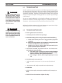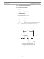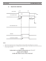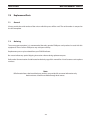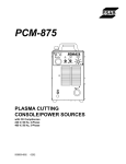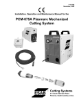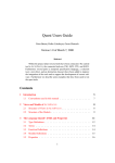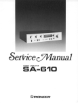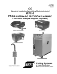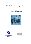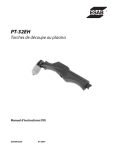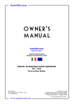
1
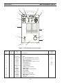
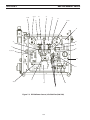
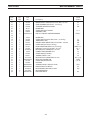
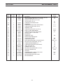
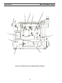
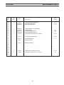
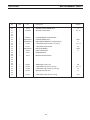
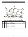
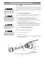
section 5 maintenance 5.1 warning Be sure that the wall disconnect switch or wall circuit breaker is open before attempting any inspection or work inside of the ESP-50. CAUTION Water or oil occasionally accumulates in compressed air lines. Be sure to direct the first blast of air away from the equipment to avoid damage to the ESP-50. If this equipment does not operate properly, stop work immediately and investigate the cause of the malfunction. Maintenance work must be performed by an experienced person, and electrical work by a trained electrician. Do not permit untrained persons to inspect, clean, or repair this equipment. Use only recommended replacement parts. 5.2 Make sure power switch on ESP-50 is in OFF position before working on the torch. warning Always replace torch with the proper torch manufactured by ESAB since it alone contains ESAB's patented safety interlock. Inspection and Cleaning Frequent inspection and cleaning of the ESP-50 is recommended for safety and proper operation. Some suggestions for inspecting and cleaning are as follows: A. B. C. D. E. F. G. warning General H. Check work cable for secured connection to workpiece. Check safety earth ground at workpiece and at power source chassis. Check heat shield on torch. It should be replaced if damaged. Check the torch electrode and cutting nozzle for wear on a daily basis. Remove spatter or replace if necessary. Make sure cable and hoses are not damaged or kinked. Make sure all plugs, fittings, and ground connections are tight. With all input power disconnected, and wearing proper eye and face protection, blow out the inside of the ESP-50 using low-pressure dry compressed air. Occasionally, bleed all water from the filter beneath the air filter-regulator. 5.3 PT-35 Torch Consumable Parts To assemble the consumable parts, refer to Figure 4-1. A. Thread electrode into torch body, hand tighten. B. Insert insulator into torch as shown. C. Place nozzle into the shield. D. Thread assembly to the torch body and hand tighten. Always make sure the shield is tight before cutting. ELECTRODE SHIELD NOZZLE TORCH BODY INSULATOR IMPORTANT! MAKE SURE SHIELD IS TIGHT! Figure 5-1. Assembly of PT-35 Torch Front End Parts 227 section 5 maintenance 5.4 IGBT Handling & Replacement Since IGBT gates are insulated from any other conducting region, care should be taken to prevent static build up, which could possibly damage gate oxides. All IGBT modules are shipped from the factory with conductive foam contacting the gate and emmiter sense pins. Always ground parts touching gate pins during installation. In general, standard ESD precautlions application to FETs should be followed. Other handling precautions that should also be observed are as follows: • • • • Use grounded work station with grounded floors and grounded wrist straps when handling devices. Use a 100Ω resistor in series with the gate when performing curve tracer tests. Never install devices into systems with power connected to the system. Use soldering irons with grounded tips when soldering to gate terminals. When mounting IGBT modules on a heatsink, certain precautions should be taken to prevent any damage against a sudden torque. If a sudden torque (“one-sided tightening”) is applied at only one mounting terminal the ceramic insulation plate or silicon chip inside the module may get damaged. The mounting screws are to be fastened in the order shown in Figure 4-3. Also, care must be taken to achieve maximum contact (i.e. minimum contact thermal resistance) for the best heat dissipation. Application of a thermal pad on the contact surface improves it thermal conductivity. See Replacement Parts section for the required pad. A torque wrench should be used. Tighten mounting screws to 28 in-lbs (3.2 m-n); wire connecting screws to 19 in-lbs (2.1 m-n). If torque is too heavy, the device can damage like the above “one-sided tightening”. Two-Point Mounting Type Temporary tightening- Final tightening- Four-Point Mounting Type Temporary tightening - Final tightening- Figure 5-2. Screw Fastening Order 228 section 6TROUBLESHOOTING 6.1Troubleshooting warning ELECTRIC SHOCK CAN KILL! Be sure that all primary power to the machine has been externally disconnected. Open the line (wall) disconnect switch or circuit breaker before attempting inspection or work inside of the power source. Check the problem against the symptoms in the following troubleshooting guide. The remedy may be quite simple. If the cause cannot be quickly located, shut off the input power, open up the unit, and perform a simple visual inspection of all the components and wiring. Check for secure terminal connections, loose or burned wiring or components, bulged or leaking capacitors, or any other sign of damage or discoloration. The cause of control malfunctions can be found by referring to the sequence of operations and electrical schematic diagram (Figure 5-1) and checking the various components. A volt-ohmmeter will be necessary for some of these checks. NOTE: Before checking voltages in the circuit, disconnect the power from the high frequency generator to avoid damaging your voltmeter. warning Voltages in plasma cutting equipment are high enough to cause serious injury or possibly death. Be particularly careful around equipment when the covers are removed. 6.2Troubleshooting GUIDE A.Power Light (PL1) does not come on. 1. Visually inspect the machine for any damage. 2.Check if the cooling fan is running. If not, then check the following : a.Check if the machine power cord is plugged to the input power receptacle. b.Measure the input power at the receptacle. If not present, then check the wall disconnect switch and it’s fuses. c.Check Fuse (F1). If fuse is ok, then check the input switch (S1) for proper operation. Replace if defective. 3. If above items check OK , the problem is internal. Send unit to an Authorized Repair Station for repair. a. If the cooling fan is running, then measure voltage between pins P2-11 and P2-14 of the control board (should be 115 VAC). If there is no voltage, then replace transformer T2. b. If the voltage is present, then the pilot light may be burnt out. B. Fault light remains on at power-up. 1. Verify start signal is not present. If so, clear start signal, fault should reset. 2. Switch power to off, verify consumables are installed correctly. C. No Air Flow 1.Check air inlet supply. Unit requires 250 CFH (118 l/m) at 60 psig 4.1 bars). 2.Check air hose and connections. Tighten if leaking. 229 section 6TROUBLESHOOTING 3. Does air flow when “air test” switch is in test position? a. If not, check torch consumables, replace if necessary. b. If above items check OK , the problem is internal. Take unit to an Authorized Repair Station for repair. D.The Power light is on, but nothing happens when the torch switch is depressed. Fault light does not activate. 1.Check the following: a. With the machine power on, depress the torch switch. On the control board the LED 1 should be lit as long as the switch is depressed. If not then check: i.Turn power off to the machine. Unplug control board. Put an ohmmeter across P5-1 and P5-2 to take resistance reading. Depress torch switch. Meter should read a short. If not, then one of the following is not working properly: ii.Torch switch or the leads. Unplug the torch switch leads at the machine. Put a meter across the two plug pins. Should read a short when the torch switch is depressed. If not, then either broken switch leads or malfunctioning switch. b.Check T2 transformer secondary voltages at the plugs P1 and P2. Refer to system schematic. Replace the transformer if the correct secondary voltages are not present. c. If everything above checks out all right, then the PCB1 Control Board should be replaced. E. Fault light activates when torch switch is closed. The Fault circuit is used to monitor conditions necessary for the safe operation of the ESP-50. The fault light will glow amber under the following conditions and operations will come to a complete stop: 1.High/Low line voltage. The Fault Light will rapidly blink on and off (5 times per second). This indicates that the input voltage is outside the “+” or “-” 15% safe operating range rating. 2.Over Temperature. The fault light will be mostly off but will blink on for 1/10th of a second, every second. This generally indicates that the duty cycle has been exceeded. Allow the power source to cool before returning to operate. a.Thermal switch may be open. It will open if the temperature at the IGBT base reaches 94°C. With the machine power off, check the continuity between P1-1 and P1-2 of the control board. If the switch is OK, then the ohmmeter should read a direct short. If not then it should read open. b. If the switch is malfunctioning, replace it. Clean the surface of the heat sink before installing the switch. 230 section 6TROUBLESHOOTING 3. Over Current. The fault light will be on continuously. This indicates that the input current to the main transformer has exceeded preset limits. a. To check if the output is shorted, remove the heat shield and nozzle from the torch and measure the resistance by putting the ohmmeter lead ”+” of the meter to “+” output terminal and Work, “-” lead of the meter to the “-” output torch terminal. Reading should be about 2 K Ohms. Reverse the voltmeter leads, the resistance reading should be less than 1.5 K Ohms. b. If the resistance reading is different than above, check the torch and output bridge. F.Air is On but nothing happens when torch switch is operated. 1.Check the torch. Make sure that the heat shield is very tight. 2.Any one of the following may not be working properly: a.Check the operation of the Thermal Switch. See D.3.a. above. b.Check Air Check switch operation. It might be stuck in On position. Pilot arc will not initiate if this switch is in the ON position. c.Measure voltage across C1 or C2 capacitor. It should be as follows: approx. 325 VDC for the 208/230 volt unit. approx. 280 VDC to 325 VDC for the 400 or 460 volt unit If not, one of following could be malfunctioning: 1).Check the capacitors C1 and C2 for any damage. 2.)Check input bridge/SCR Module (IBR) This can be checked without taking it out of the circuit using an volt/ohmeter. Replace it if found malfunctioning. Follow bridge installation instructions. 3.)Check Inrush current resistor, R10, located on the input bridge heat sink. Replace it if malfunctioning. d. IGBTs (2 on 230 V, and 1 on the 400 V & 460 V units) may be blown. See IGBT installation procedure. Before replacing IGBTs, make sure to check the zener diodes and pico fuses on the IGBT driver boards. G.Pilot Arc is on but Main Arc does not transfer. 1.Make sure work clamp is connected to work material. 2.Check the torch. Replace consumables if necessary. 231 section 6TROUBLESHOOTING H.Poor Cutting Performance. 1. Check air supply regulator . It should be adjusted to 65 - 75 psig (4.5 - 5.2 bars). 2. The air supplied to the torch should be free of oil and water. 3. Make sure the consumables in the torch are acceptable. 4. Check the output. Use a calibrated current probe capable of measuring 100 amps. I. Air does not shut off. 1.Check air test, the gas solenoid valve is energized when the switch is in the “on” position. a.Check voltage to solenoid coil, if present when torch switch is un- plugged, replace PCB1. b. Turn off primary power to the power source. If gas continues to flow, replace the gas solenoid. c. Turn on primary power and check the status of the Fault light. If the Fault light is on continuously and gas is on continuously, turn off primary power and inspect the torch for proper assembly of the electrode and nozzle. Press firmly on the electrode and verify that it retracts when pressed, and returns forward when released. d. Reassemble the electrode and nozzle and turn on primary power. After approximately two seconds the gas should come on briefly then go off. If the Fault light comes on continuously and gas remains off, check for defective torch trigger or shorted torch trigger leads. I. Main arc is difficult to start. J. Main arc is difficult to start. 1.The most common reason is worn or missing consumables. Check and replace if necessary. 2. Input air must be clean and dry. 3. Input air pressure must be between 65 - 75 psig (4.5 - 5.2 bars). 4.Torch connections must be tight. 5. Work cable and clamp must be in good condition and must make a good electrical connection to the material to be cut. 6. If above items check OK , the problem may be internal. a.Missing or weak pilot arc. Check pilot arc resistors and pilot arc wiring. Send unit to an Authorized Repair Station for repair. 232 section5 6TROUBLESHOOTING SECTION TROUBLESHOOTING 5.36.3Reference REFERENCE VOLTAGE CHECKS Voltage Checks A. A.Control Control Board (PCB1) BoardAssembly Assembly (PCB1) 1. 1.LED’s LED’s LED-1 - -Torch Torch Switch LED-1 Switch LED-3 - - Gas Solenoid Valve LED-3 Gas Solenoid Valve Test 2. 2.Voltage Voltage TestPoints Points are no arc. arc. Tests Tests aremade madewith withpower power on on -- no TP-0 TP-0 TP-1 TP-1 TP-2 TP-2 TP-3 TP-3 TP-4 TP-4 TP-9 TP-9 TP-10 - TP-10 Ground - Ground +15 vdc - +15 vdc +12 vdc - +12 vdc -12-12 vdc - vdc +5+5 vdc - vdc IGBT’s KHz - IGBT’sdriving drivingsignal signal- -switching switchingfrequency frequency = = 20 20 KHz - switching frequency IGBT’sIGBT’s driving driving signal - signal switching frequency = 20 KHz= 20 KHz 50 µsec 40 usec - LPG50 50 usec - LPG80 13 vdc 0 6 usec - LPG50 9 usec - LPG80 -13 vdc For 208/230 VACVAC input, the the IGBT offoff time is is 3µsec. For 208/230 input, IGBT time 3µsec. For 400/460 VACVAC input, the the IGBT offoff time is is 3µsec. For 400/460 input, IGBT time 3µsec. Figure 5.1 6.1 IGBT Gating Signal Figure IGBT Gating Signal 233 33 section 6TROUBLESHOOTING 6.4 Sequence of Operation ON START SIGNAL OFF OPEN GAS SOLENOID VALVE .5 SEC. CLOSE 10 SEC POSTFLOW PREFLOW FAULT OVERLOAD LIGHT INVERTER CUTTING ARC (CURRENT) NOTES: 1. 2. When the start signal is turned "on" during postflow period, the postflow and preflow times are canceled. When the amber fault light comes on, cutting operation should be stopped. The postflow time starts from the moment the start signal is removed. NOTE: Schematics and Wiring Diagrams on 11” x 17” paper are included inside the back cover of this manual. 234 section 7 replacement parts 7.0Replacement Parts 7.1 General Always provide the serial number of the unit on which the parts will be used. The serial number is stamped on the unit nameplate. 7.2Ordering To ensure proper operation, it is recommended that only genuine ESAB parts and products be used with this equipment. The use of non-ESAB parts may void your warranty. Replacement parts may be ordered from your ESAB Distributor. Be sure to indicate any special shipping instructions when ordering replacement parts. Refer to the Communications Guide located on the back page of this manual for a list of customer service phone numbers. Note Bill of material items that have blank part numbers are provided for customer information only. Hardware items should be available through local sources. 235 section 7 replacement parts 3, 4 5, 4 6 8, 9 7 1, 2 16 15 17 10, 11 14 13 12 Figure 7-1. ESP-50 Power Source, Front View Item No. Qty. Req. Part No. Description 1 1 137630611 2 1 0558001176 3 1 897W65 4 2 951474 5 1 634518 6 1 951754 7 1 951814 8 2 0558003378 9 1 21711 10 1 23606172 11 1 680560 12 4 182W12 13 1 0558004314 14 1 36330YL 15 1 954008 16 2 13734588 17 1 993426 Circuit Symbol KNOB POT. 10K 3W (NOMEX INSUL. - 676876) SWITCH TOGGLE SPST 3 POS 15 A 125 V SWITCH SEAL BLACK SWITCH TOGGLE DPDT 2 POS 15 A 125 V LAMP LED YEL 12 V LAMP NEON WHITE GAUGE HOUSING GAUGE 1.50 160 PSI WHITE STRAIN RELIEF WORK CABLE 25 FT. (Not Shown) FOOT RUBBER CHASSIS ESP-50 DOOR ACCESS YEL (ESAB) LABEL WARNING HI VOLTAGE LABEL ESAB GROMMET 1.5 X 1.75 X .06 236 R1 S3 S2 PL2 PL1 section 7 replacement parts 154, 155, 156, 164 153 151, 152 158, 159 160, 161 162 Figure 7-2. ESP-50 Power Source, Rear View Item No. Qty. Req. Part No. Description 151 152 153 154 155 156 157 158 159 160 161 162 1 1 2 1 1 1 21710 10Z30 951575 36719YL 2091514 954290 1 1 1 1 1 1 952136 952559 97W63 37573 0558001181 36107 Circuit Symbol FILTER REGULATOR ADAPTOR B/A-WM x 1/4 NPTM HANDLE TOP COVER YEL LABEL WARNING LABEL WARNING FUSE HOLDER FUSE 3 A FAST ACTING STRAIN RELIEF INPUT POWER CABLE, 6 FT (208/230 V) INPUT POWER CABLE, 10 FT (400CE/460 V) SWITCH POWER 600V 63A 237 F1 S1 section 7 replacement parts 29, 30 25, 26 36 39 27 35 27 25, 26 41 24 35 45 31 43 32, 33, 34 23 21 37 46, 47 38 44 40 Figure 7-3. ESP-50 Power Source, Left Side View (208/230) 238 section 7 Item No. 21 22 23 24 25 26 27 28 29 30 31 32 33 34 35 36 37 38 39 40 41 42 43 44 45 46 47 48 Qty. Req. replacement parts Part No. Description Circuit Symbol 1 1 1 1 2 2 2 952150 952002 952208 36731 952237 994674 0558001177 BRIDGE 60ADC 100NS 600 V (includes PAD - 951192) CORE SATURABLE (Not shown - see wiring) STANDOFF INSULATING NYLON BUSBAR NEG CAPACITOR 1800 µf 450VDC GROMMET STRIP PCB ASS'Y MOSFET IGBT DRIVER BOARD 1 1 1 1 1 3 2 1 1 1 1 4 1 2 1 1 1 1 2 1 36730 951028 950487 952235 2062282 951321 951205 17750010 32958 952255 950711 17721020 0558038258 951940 952558 0558004447 0558002436 17250010 99512068 0558003105 BUSBAR POS CAPACITOR 1µf 630VDC (Not shown - see wiring) TERM BLOCK 2 POS MODULE INPUT BRIDGE/SCR (includes PAD - 952280) CAPACITOR .22µf 1KV (See wiring) METAL OXIDE VARISTOR 275 V (See wiring) IGBT 600 V 100 A (includes PAD - 951190) RESISTOR 50 W 10 OHM (PAD - 951194) CURRENT TRANSFORMER ASS'Y CAPACITOR 40 µf 400 VDC THERMAL SWITCH 194°F RESISTOR 24 W 20 OHMS (PAD 951193) PILOT ARC CONTROL PCB CAPACITOR 1µf 630W VDC HEATSINK SOLENOID VALVE 1/4NPT NC 24 VAC DIODE SINGLE FAST RECOV RESISTOR WW FIXED 50W 10 OHM RESISTOR BRACKET PRESSURE SWITCH 239 D1 L3 TB3 C1, 2 PCB2, 3 C3 TB5 IBR C19 MOV1, 2, 3 Q1, 2 R7 T4 C4 TS1 R3, 4, 5, 6 PCB4 C15, 16 SOL1 D2 R10 PS1 section 7 replacement parts 56, 57, 58 61 71 67 59 56, 57, 58 60 73 48 55 62 76 53 63 64, 65, 66 51 54 77, 78 68 74 69 75 72 Figure 7-4. ESP-50 Power Source, Left Side View (400CE/460) 240 section 7 replacement parts Item Qty. Part No. Req. No. Description 51 1 952150 BRIDGE 60 ADC 100NS 600 V (includes PAD - 951192) 52 1 952002 CORE SATURABLE (Not shown - see wiring) 53 1 951800 MODULE DUAL IGBT 150 A, 1200 V (includes PAD - 951191) 54 1 952208 STANDOFF INSULATING NYLON 55 1 36732 BUSBAR POS 56 2 952237 CAPACITOR 1800µf 450 VDC (400CE/460 V) 2 952562 CAPACITOR 1800µf 500 VDC (575 V) 57 2 994674 GROMMET STRIP 58 2 951028 CAPACITOR 1µf 630 VDC (See wiring) 59 1 0558001178 PCB ASS'Y IGBT DRIVER BOARD 60 1 951964 CAPACITOR 2µf 800 VDC (400CE/460V) 61 1 36822 HOSE ASS'Y B/A x 1/4 NPT RUB 62 1 36733 BUSBAR NEG 63 1 950487 TERM BLOCK 2 POS 64 1 952235 MODULE INPUT BRIDGE/SCR (includes PAD - 952280) 65 1 2062282 CAPACITOR .22µf 1KV 66 3 950591 METAL OXIDE VARISTOR 510 V (400CE/460 V) 67 2 17750010 RESISTOR 50W 10 OHM (PAD - 951194) 68 1 32958 CURRENT TRANSFORMER ASS'Y 69 1 952255 CAPACITOR 40µf 400 VDC (400CE/460 V) 70 1 058004394 INDUCTOR, PILOT ARC 71 1 950711 THERMAL SWITCH 194°F 72 4 17721020 RESISTOR 25W 20 OHMS (PAD - 951193) 73 1 0558038258 PILOT ARC CONTROL PCB 74 1 952558 HEATSINK 75 1 950249 SOLENOID VALVE 1/4 NPT 165 PSI 24 VAC 76 1 0558002436 DIODE SINGLE FAST RECOV 77 1 17250010 RESISTOR WW FIXED 50W 10 OHM 78 2 99512068 RESISTOR BRACKET 241 Circuit Symbol D1 L3 Q1 TB3 C1, 2 C1, 2 C3, 15 PCB2 C16 TB5 IBR C19 MOV1, 2, 3 R7 T4 C4 L4 TS1 R3, 4, 5, 6 PCB4 SOL1 D2 R10 section 7 replacement parts 86 87 88 81 93 80 94 70 96 Figure 7-5. ESP-50 Power Source, Right Side View (208/230) 242 section 7 Item No. 80 81 82 83 84 85 86 87 88 89 90 91 92 93 94 95 96 97 98 99 100 101 102 103 104 105 Qty. Req. replacement parts Part No. Description Circuit Symbol 1 2 1 35940 17300008 0558004394 CONTROL TRANSFORMER ASS'Y RESISTOR 300W 8 OHM INDUCTOR, PILOT ARC T2 R11,12 L4 1 1 1 1 2 23604891 952232 0558038261 0558004395 951469 LABEL WARNING HI VOLTAGE RED INDUCTOR PFC CONTROL BOARD ASS'Y MAIN TRANSFORMER ASS'Y CAPACITOR .022µf 250 VAC (See Wiring) L2 PCB1 T1 C17, 18 2 951515 CAPACITOR .047µf 660 VAC C21,C23 1 1 952233 36721 INDUCTOR OUTPUT BUSBAR OUTPUT 1 36717 BRACKET OUTPUT 2 1 672348 952204 CAPACITOR .01µf 1KV (See wiring) CAPACITOR .01µf 250 VAC (See wiring) 243 L1 C11, 12 C9 section 7 replacement parts 117 116 111 122 82 123, 135 125 121 110 133 Figure 7-6. ESP-50 Power Source, Right Side View (400CE/460) 244 section 7 Item No. 110 111 112 113 114 115 116 117 118 119 120 121 122 123 124 125 126 127 128 129 130 131 132 133 134 135 Qty. Req. replacement parts Part No. Description 1 1 32914 17300008 1 1 1 2 Circuit Symbol CONTROL TRANSFORMER ASS'Y RESISTOR 300W 8 OHM T2 R11,12 23604891 0558038261 0558004395 951469 LABEL WARNING HI VOLTAGE RED CONTROL BOARD ASS'Y MAIN TRANSFORMER ASS'Y (400CE/460 V) CAPACITOR .022µf 250 VAC (See wiring) PCB1 T1 C17, 18 1 1 1 1 951515 0455803881 952233 36721 CAPACITOR .047µf 660 VAC EMF FILTER BOARD INDUCTOR OUTPUT BUSBAR OUTPUT 1 36717 BRACKET OUTPUT KYDEX 1 2 1 1 950487 672348 952204 952213 TERM BLOCK 2 POS 20 A CAPACITOR .01µf 1KV (See wiring) CAPACITOR .01µf 250 VAC (See wiring) REACTOR 3PH LINE 12 A 1 951314 CAPACITOR .022µf 1KV (See wiring) 245 C23 PCB5 L1 TB1 C11, 12 C9 L2 C20 section 7 replacement parts 142 143 140 145 144 141 Figure 7-7. ESP-50 (208/230V) Power Source, Top View with PCB1 and Shelf Removed Item No. Qty. Req. 140 141 142 143 144 145 1 1 2 1 1 1 1 Part No. Description 954673 952026 17240310 951182 2091558 954700 954681 Circuit Symbol LABEL CNC INTERFACE TERM BLOCK 7 POS 25 A RESISTOR 10 K 25 W FAN AC AXIAL LABEL GROUND BLACK LABEL INPUT (208/230 V) LABEL INPUT (400CE/460 V) 246 TB4 R2, 15 M1 section 7 replacement parts 247 notes 248 revision history 1. Original release of this manual: 02/2004. 2. 04/2004 Revision - added Pierce Height to cut data charts. 3. 01/2005 Revision - Section 2 - Chgd electrode p/n from: 0558004355 to: 0558005200 in cut data charts. Added p/n's 0558004973 & 0558004974 for ESP-50 208/230 V PT-35 packages without rack. |Updated torch specifications figure 2-1 & 2-2 drawing. Updated spare parts kits with new p/n 0558005210, consumable value pack p/n 0558005203, consumable set p/n 0558005201 & consumable set p/n 0558005202. Section 4 - Updated figure 4-2 to show new electrode drawing. Created schematic pack (with new p/n's 0558004710 & 0558004711) for back cover insert. 4. Revision - 05/2005 - added Air Line Filter Regulator p/n 0558005394 note in Replacement Parts section per CN #053013. 5. Revision - 01/2006 - Removed filter regulator, item 151, p/n 0558005394 note, in replacement parts section per D. Smith. 6. Revision - 10/2007 - Updated info with 380/400 designations & updated disclaimer. 249 ESAB subsidiaries and representative offices Europe AUSTRIA ESAB Ges.m.b.H Vienna--Liesing Tel: +43 1 888 25 11 Fax: +43 1 888 25 11 85 BELGIUM S.A. ESAB N.V. Brussels Tel: +32 2 745 11 00 Fax: +32 2 726 80 05 THE CZECH REPUBLIC ESAB VAMBERK s.r.o. Prague Tel: +420 2 819 40 885 Fax: +420 2 819 40 120 DENMARK Aktieselskabet ESAB Copenhagen--Valby Tel: +45 36 30 01 11 Fax: +45 36 30 40 03 FINLAND ESAB Oy Helsinki Tel: +358 9 547 761 Fax: +358 9 547 77 71 FRANCE ESAB France S.A. Cergy Pontoise Tel: +33 1 30 75 55 00 Fax: +33 1 30 75 55 24 GERMANY ESAB GmbH Solingen Tel: +49 212 298 0 Fax: +49 212 298 204 GREAT BRITAIN ESAB Group (UK) Ltd Waltham Cross Tel: +44 1992 76 85 15 Fax: +44 1992 71 58 03 ESAB Automation Ltd Andover Tel: +44 1264 33 22 33 Fax: +44 1264 33 20 74 HUNGARY ESAB Kft Budapest Tel: +36 1 20 44 182 Fax: +36 1 20 44 186 ITALY ESAB Saldatura S.p.A. Mesero (Mi) Tel: +39 02 97 96 81 Fax: +39 02 97 28 91 81 THE NETHERLANDS ESAB Nederland B.V. Utrecht Tel: +31 30 248 59 22 Fax: +31 30 248 52 60 NORWAY AS ESAB Larvik Tel: +47 33 12 10 00 Fax: +47 33 11 52 03 POLAND ESAB Sp.z.o.o Warszaw Tel: +48 22 813 99 63 Fax: +48 22 813 98 81 PORTUGAL ESAB Lda Lisbon Tel: +351 1 837 1527 Fax: +351 1 859 1277 SLOVAKIA ESAB Slovakia s.r.o. Bratislava Tel: +421 7 44 88 24 26 Fax: +421 7 44 88 87 41 SPAIN ESAB Ibérica S.A. Alcobendas (Madrid) Tel: +34 91 623 11 00 Fax: +34 91 661 51 83 SWEDEN ESAB Sverige AB Gothenburg Tel: +46 31 50 95 00 Fax: +46 31 50 92 22 ESAB International AB Gothenburg Tel: +46 31 50 90 00 Fax: +46 31 50 93 60 SWITZERLAND ESAB AG Dietikon Tel: +41 1 741 25 25 Fax: +41 1 740 30 55 North and South America ARGENTINA CONARCO Buenos Aires Tel: +54 11 4 753 4039 Fax: +54 11 4 753 6313 Asia/Pacific AUSTRALIA ESAB Australia Pty Ltd Ermington Tel: +61 2 9647 1232 Fax: +61 2 9748 1685 CHINA Shanghai ESAB A/P Shanghai Tel: +86 21 6539 7124 Fax: +86 21 6543 6622 INDIA ESAB India Ltd Calcutta Tel: +91 33 478 45 17 Fax: +91 33 468 18 80 INDONESIA P.T. Esabindo Pratama Jakarta Tel: +62 21 460 01 88 Fax: +62 21 461 29 29 MALAYSIA ESAB (Malaysia) Snd Bhd Selangor Tel: +60 3 703 36 15 Fax: +60 3 703 35 52 SINGAPORE ESAB Singapore Pte Ltd Singapore Tel: +65 861 43 22 Fax: +65 861 31 95 Representative offices BULGARIA ESAB Representative Office Sofia Tel/Fax: +359 2 974 42 88 EGYPT ESAB Egypt Dokki--Cairo Tel: +20 2 390 96 69 Fax: +20 2 393 32 13 ROMANIA ESAB Representative Office Bucharest Tel/Fax: +40 1 322 36 74 RUSSIA-- CIS ESAB Representative Office Moscow Tel: +7 095 937 98 20 Fax: +7 095 937 95 80 ESAB Representative Office St Petersburg Tel: +7 812 325 43 62 Fax: +7 812 325 66 85 Distributors For addresses and phone numbers to our distributors in other countries, please visit our home page www.esab.com ESAB Asia/Pacific Pte Ltd Singapore Tel: +65 861 74 42 Fax: +65 863 08 39 SOUTH KOREA ESAB SeAH Corporation Kyung--Nam Tel: +82 551 289 81 11 Fax: +82 551 289 88 63 UNITED ARAB EMIRATES ESAB Middle East Dubai Tel: +971 4 338 88 29 Fax: +971 4 338 87 29 BRAZIL ESAB S.A. Contagem--MG Tel: +55 31 333 43 33 Fax: +55 31 361 31 51 CANADA ESAB Group Canada Inc. Missisauga, Ontario Tel: +1 905 670 02 20 Fax: +1 905 670 48 79 MEXICO ESAB Mexico S.A. Monterrey Tel: +52 8 350 5959 Fax: +52 8 350 7554 USA ESAB Welding & Cutting Products Florence, SC Tel: +1 843 669 44 11 Fax: +1 843 664 44 58 ESAB AB SE-- 695 81 LAXÅ SWEDEN Phone +46 584 81 000 Fax +46 584 123 08 www.esab.com 0558005310 10 / 2007