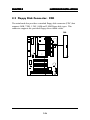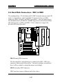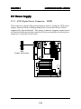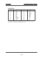
1
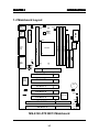
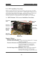
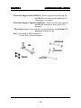
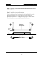
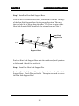
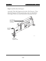
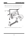
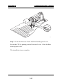
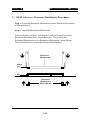
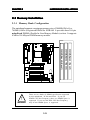
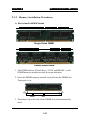
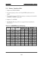
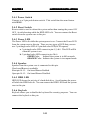
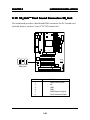
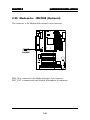
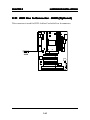
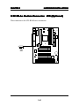
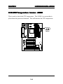
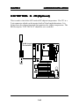
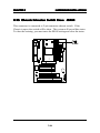
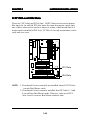
CHAPTER 1 INTRODUCTION Chapter 1 INTRODUCTION The MICRO ATX BX13 mainboard is a high-performance personal computer mainboard based on the Intel® Pentium® II processor. The Intel® Pentium® II processor supports MMXTM (Multimedia Extension) technology. The mainboard uses the highly integrated Intel® 82443BX AGP chipset to support the PCI/ISA and Green standards, and to provide the Host/AGP bridge. The Intel® 82371EB chipset integrates all system control functions such as ACPI (Advanced Configuration and Power Interface). The ACPI provides more Energy Saving Features for the OSPM(OS Direct Power Management) function. The Intel® 82371EB chipset also improves the IDE transfer rate by supporting Ultra DMA/33 IDE that transfers data at the rate of 33MB/s. The mainboard also supports the System Hardware Monitor Controller. Its functions include: CPU /power supply/chassis fan revolution detect, CPU/ system voltage monitor, system temperature monitor, chassis intrusion detect and TOP TECH II as an optional function. 1-1 CHAPTER 1 INTRODUCTION 1.1 Mainboard Features CPU l Slot 1 for Intel® Pentium® II/CeleronTM processor. l Supports 233MHz, 266MHz, 300MHz, 333MHz, 350MHz, 400MHz, 450MHz, and faster. Chipset l Intel® 82443BX/PIIX4E chipset. FSB (Front Side Bus) l 66.6MHz, 100MHz and faster clocks are supported. Main Memory l Supports six memory banks using three 168-pin unbuffered DIMM. l Supports a maximum memory size of 384MB (8M x 8) or 768MB (16M x 4) registered DIMM only. l Supports ECC(1-bit Error Code Correct) function. l Supports 3.3v SDRAM DIMM. Slots l One AGP slot. - AGP specification compliant - AGP 66/133MHz 3.3v device support l Five 32-bit Master PCI Bus slots and two 16-bit ISA Bus slots (wherein one slot is shared). *See Chapter 2-27 for further details on PCI slots. l Supports 3.3v/5v PCI bus Interface. On-Board IDE l An IDE controller on the Intel® PIIX4E PCI Chipset provides IDE HDD/ CD-ROM with PIO, Bus Master and Ultra DMA/33 operation modes. l Can connect up to four IDE devices. 1-2 CHAPTER 1 INTRODUCTION On-Board Peripherals l On-Board Peripherals include: - 1 floppy port supports 2 FDD with 360K, 720K, 1.2M, 1.44M and 2.88Mbytes. - 2 serial port (COM A) + (COM B) - 1 parallel port supports SPP/EPP/ECP mode - 2 USB ports - 1 IrDA connector for SIR. - 1 Audio port ( Line_Out, Line_In, and Mic_In Jack) and 1 MIDI/ Game Port Audio (Optional) l Creative® ES1373 - Running on PCI BUS. - 64 Voice and AC3 Capable - Support Direct Sound and Direct Sound 3D - AC97’ Compliant - Support SPDIFTM output BIOS l The mainboard BIOS provides “Plug & Play” BIOS which detects the peripheral devices and expansion cards of the board automatically. l The mainboard provides a Desktop Management Interface(DMI) function which records your mainboard specifications. l ACPI(Advanced Configuration and Power Interface) feature. Dimension l ATX Form Factor : 30cm(L) x 19.2cm(W) x 4 layers PCB Mounting l 6 mounting holes. 1-3 CHAPTER 1 INTRODUCTION System Hardware Monitor l CPU/Power Supply/Chassis Fan Revolution Detect l CPU Fan Control detects the CPU temperature, then determine the FAN SPEED, which utilizes PC Alert program (the fan will automatically stop when the system enters suspend mode) l System Voltage Detect l Added 5VSB and Battery Voltage Detect l CPU Overheat Warning. l Display Actual Current Voltage l Chassis Intrusion Other Features l Keyboard Password Wake-Up l LAN Wake-Up l Internal/External Modem Wake-Up 1-4 CHAPTER 1 INTRODUCTION 1.2 Mainboard Layout Top: Mouse JKBV CPUFAN PSFAN Bottom: Keyboard IR JSOR1 DIMM 3 SLOT 1 JT3 JRMS1 IDE1 IDE2 Top: Midi/ Game Port JPHONE: MDM_IN DIMM 2 FW82443BX DIMM 1 Bottom: COM 1/ COM 2 WINBOND W83977EF-AW FDD Top: LPT Bottom: Line-Out Line-In Mic BIOS Bottom: Port 2 JCASE System Hardware Monitor (optional) ATX Power Supply USB Top: Port 1 SW2 JAUX: AUX_IN AGP SLOT JCD: CD_IN PCI SLOT 1 Creative ES1373 (Optional) PCI SLOT 2 BATT PCI SLOT 3 + JMDM1 SB_Link JWOL1 PCI SLOT 4 JBAT1 FW82371EB JMDM1 JFP PCI SLOT 5 JGS1 ISA SLOT 1 SYSFAN ISA SLOT 2 MS-6163 ATX BX13 Mainboard 1-5 CHAPTER 2 HARD WARE INST ALLA TION HARDW INSTALLA ALLATION Chapter 2 HARDWARE INSTALLATION 2.1 Central Processing Unit: CPU This mainboard operates with Intel® Pentium® II/CeleronTM processor. The mainboard uses a CPU Slot called Slot 1 for easy CPU installation. The CPU should always have a Heat Sink and a cooling fan attached to prevent overheating. 2-1 CHAPTER 2 HARD WARE INST ALLA TION HARDW INSTALLA ALLATION 2.1-1 CPU Installation Procedures Different kinds of Pentium® II processor that is currently used: the OEM version, the Boxed version, and CeleronTM. OEM Pentium® II Processor has no Heat Sink, Fan and Heat Sink Support, the Boxed Pentium® II Processor is provided with Heat Sink w/ fan and Heat Sink Support, while the CeleronTM processor is a plain processor card without cover or heatsink. A. OEM Pentium® II Processor Installation Procedures Processor Lock Heat Sink W/Fan Pentium® II Processor Notch Hole Retention Mechanism Heat Sink Support Top Bar Heat Sink Support Base Heat Sink Support Pin Required Things: Pentium® II processor - Processor. *Retention Mechanism(RM) - Plastic Guide that holds the S.E.C. Catridge in the Slot 1 connector. *Retention Mechanism Attach Mount(RMAM) - Bolt/Bridge assemblies inserted up through the bottom of the motherboard. RM secures to RMAM ( 2 RMAM required per RM ). *Heat Sink Support Base (HSSBASE) - Plastic support bar mounted to the mainboard under the ATX heatsink. (One leg is always bigger than the other one) 2-2 CHAPTER 2 HARD WARE INST ALLA TION HARDW INSTALLA ALLATION *Heat Sink Support Pin (HSSPIN) - Plastic pins inserted through the HSSBASE to secure it to the mainboard (2 required per Assembly). *Heat Sink Support Top Bar (HSSTOP) - Plastic bar that clips onto the HSSBASE through the fins on the ATX heatsink. **Heat Sink w/ fan - Heat Sink that can be attached to the Pentium® II processor with metal clip. Note: * Provided by MSI mainboard. ** Provided by Special request. HSSBASE RM HSSPIN RMAM HSSTOP 2-3 CHAPTER 2 HARD WARE INST ALLA TION HARDW INSTALLA ALLATION Step 1: Insert the Retention Mechanism Attach Mount at the bottom of the mainboard. Step 2: Install the Retention Mechanism. Look for the key on Slot 1, and match it with the Notch Key on the Retention Mechanism for proper direction. Then, attach the Retention Mechanism to the Retention Mechanism Attach Mount. Use a Screwdriver to secure the Retention Mechanism. Retention Mechanism ê Retention Mechanism Attach Mount ê ê Notch Key Key SLOT1 2-4 ê CHAPTER 2 HARD WARE INST ALLA TION HARDW INSTALLA ALLATION Step 3: Install the Heat Sink Support Base. Look for the Two holes across Slot 1, and match it with the Two legs of the Heat Sink Support Base for the proper direction. Take note that one hole/leg is bigger than the other. The Four top pins of the Heat Sink Support Base should also be oriented towards Slot 1. pins Heat Sink Support Pin Leg Heat Sink Support Base Push the Heat Sink Support Base onto the mainboard, until you hear a click sound. Check for a perfect fit. Step 4: Install the Heat Sink Support Pin. Push the Heat Sink Support Pins onto the two holes of the Heat Sink Support Base. Check for a perfect fit. These pins are used to secure the Heat Sink Support Base. 2-5 CHAPTER 2 HARD WARE INST ALLA TION HARDW INSTALLA ALLATION Step 5: Install the Heat Sink with Fan to the Processor. Push down the metal clips, so that they are in line with the back of the Heat Sink. Be careful, so as not detach the metal clips from the Heat Sink. Heat Sink w/ Fan â should be The arrow pointing down. Heat Sink Base Holder Metal Clips In case the metal clips are detached from the Heat Sink, re-attach them. Look for the arrow on the metal clip. This arrow should be pointing down and aligned with the Heat Sink Support Base Holder. Attach the Heat Sink to the processor. Metal Clips Ear Clip Holder Secure Posts Secure holes Clip Holder Metal Clips Ear S.E.C. Cartridge - Thermal P Isometric View Pentium® II Processor (Back) Heat Sink w/ Fan(Back) - Look at the back of the Heat Sink and take note of the 2 secure posts. Insert these 2 Secure posts to the 2 secure holes on the back of the processor. - Align the ears of the metal clips with the clip holders on the back of the processor. Use a screw driver to push the metal clips onto the clip holders. Check for a perfect fit. 2-6 CHAPTER 2 HARD WARE INST ALLA TION HARDW INSTALLA ALLATION Step 6: Install the Processor. Unlock the Processor by pushing in the Processor Locks. è ç Insert the Processor like inserting a PCI or an ISA card. Step 7: Lock the Processor Locks. Secure the CPU by pulling the Processor Locks out. è ç 2-7 CHAPTER 2 HARD WARE INST ALLA TION HARDW INSTALLA ALLATION Step 8: Install the Heat Sink Support Top Bar. Push the Heat Sink Support Top Bar to the Heat Sink Support Base, Until you hear a “click” sound. Check for a perfect fit. Heatsink Support Top Bar The installation is now complete. 2-8 CHAPTER 2 HARD WARE INST ALLA TION HARDW INSTALLA ALLATION B. Boxed Pentium® II Processor Installation Procedures The Boxed Pentium® II Processor has a built- in Fan and Heat Sink. It also has a Heat Sink Support. So if you’re going to use a Boxed PentiumTM II Processor, all you need is the Retention Mechanism. Step 1: Insert the Retention Mechanism Attach Mount at the bottom of the mainboard. Step 2: Install the Retention Mechanism. Look for the key on Slot 1, and match it with the Notch Key on the Retention Mechanism for proper direction. Then, attach the Retention Mechanism to the Retention Mechanism Attach Mount. Use a Screwdriver to secure the Retention Mechanism. Retention Mechanism ê Retention Mechanism Attach Mount ê ê Notch Key Key SLOT1 2-9 ê CHAPTER 2 HARD WARE INST ALLA TION HARDW INSTALLA ALLATION Step 3: Install the Heat Sink Support Base. Look for the 2 holes across Slot 1, and match it with the 2 Heat Sink Support Base. Take note that one hole/base is bigger than the other. Retention Mechanism Notch Hole PC-3742 Heat Sink Support Base Push the Heat Sink Support Base onto the mainboard, until you hear a click sound. Check for a perfect fit. 2-10 CHAPTER 2 HARD WARE INST ALLA TION HARDW INSTALLA ALLATION Step 4: Install the Heat Sink Support. Attach the 2 Heat Sink Supports to the sides of the Processor. These Heat Sink Supports will fit in any direction, so be sure that the Heat Sink Support Locks are oriented outwards for the proper direction. Intel® Boxed Pentium® II Processor Heat Sink Support PC-3743 Heat Sink Support Lock 2-11 CHAPTER 2 HARD WARE INST ALLA TION HARDW INSTALLA ALLATION Step 5: Unlock the Processor Locks and Heat Sink Support Locks. Push in the Processor Locks. Open the Heat Sink Support Locks. Processor Lock Heatsink Support Lock PC-3744 Step 6: Insert the Processor like inserting a PCI or an ISA card. 2-12 CHAPTER 2 HARD WARE INST ALLA TION HARDW INSTALLA ALLATION PC-3745 Step 7: Lock the Processor Locks and Heat Sink Support Locks Secure the CPU by pushing out the Processor Locks. Close the Heat Sink Support Locks. The installation is now complete. 2-13 CHAPTER 2 HARD WARE INST ALLA TION HARDW INSTALLA ALLATION C. OEM CeleronTM Processor Installation Procedures Step 1: Insert the Retention Mechanism Attach Mount at the bottom of the mainboard. Step 2: Install the Retention Mechanism. Look for the key on Slot 1, and match it with the Notch Key on the Retention Mechanism for proper direction. Then, attach the Retention Mechanism to the Retention Mechanism Attach Mount. Use a Screwdriver to secure the Retention Mechanism. Retention Mechanism ê Retention Mechanism Attach Mount ê ê Notch Key Key SLOT1 2-14 ê CHAPTER 2 HARD WARE INST ALLA TION HARDW INSTALLA ALLATION Step 3: Install the MSI Heat Sink (optional) to the Processor. ê Celeron TM processor Heat Sink ê The instruction procedure may vary depending on the Heat Sink that you’re using. plastic Clip Push down the plastic clips, so that they are in line with the hole on the processor. Check for perfect fit. Step 4: Install the Processor. Insert the Processor like inserting a PCI or an ISA card. Step 5: Lock the Processor. MSI Retention Cap ê ê Notch Hole Notch Hole Lock the processor by putting the MSI Retention Cap provided. The MSI Retention Cap will only fit in one direction. The MSI Retention Cap is only used with Intel® CeleronTM processor and Intel® Penitum® II processor (S.E.C.C. 2). 2-15 CHAPTER 2 HARD WARE INST ALLA TION HARDW INSTALLA ALLATION Procedure for detaching the MSI Retention Cap: Retention Cap Lock MSI Retention Cap (Top View) To remove the Retention Cap. - Pull the the Retention Cap Lock outward. - Pull one side upward at a time. 2-16 CHAPTER 2 HARD WARE INST ALLA TION HARDW INSTALLA ALLATION 2.1-2 CPU Core Speed Derivation Procedure 1. This mainboard can auto-detect the Core/Bus (Fraction) ratio of the CPU If then CPU Clock = Core/Bus ratio = CPU core speed = = = 2-17 66MHz 3.5 Host Clock x Core/Bus ratio 66MHz x 3.5 233MHz CHAPTER 2 HARD WARE INST ALLA TION HARDW INSTALLA ALLATION 2.1-3 CPU Bus Frequency Selector: SW2 The SW2 is used to set the CPU Bus Frequencies from 66MHz to 100MHz. When SW2 is shorted, this will automatically detect the CPU Bus Frequency. When SW2 is open, if you used 66MHz CPU Bus Frequency, this will set it virtually into 100MHz. SW2 SW2 Feature Automatically detect 66MHz and 100MHz CPU Bus Frequency Virtually set 66MHz CPU Bus Frequency into 100MHz NOTE: 1. This feature works with 66MHz FSB only. 2. If your CPU FSB supports 66MHz and you want to run it on 100MHz FSB, the SW2 should be open. The AGP Bus will be set to run at 100MHz x 2/3=66MHz to make it stable. 2-18 CHAPTER 2 HARD WARE INST ALLA TION HARDW INSTALLA ALLATION 2.1-4 Fan Power Connectors: CPUFAN/PSFAN/SYSFAN These connectors support system cooling fan with +12V. It supports three pin head connector. When connecting the wire to the connector, always take note that the red wire is the positive and should be connected to the +12V, the black wire is Ground and should be connected to GND. If your mainboard has System Hardware Monitor chipset on-board, you must use a specially designed fan with speed sensor to take advantage of this function. +12V GND SENSOR SENSOR +12V GND PSFAN CPUFAN SYSFAN SENSOR +12V GND PSFAN : Power Supply Fan CPUFAN : Processor Fan SYSFAN : System(Chassis) Fan For fans with fan speed sensor, every rotation of the fan will send out 2 pulses. System Hardware Monitor will count and report the fan rotation speed. Note: 1. Always consult vendor for proper CPU cooling fan. 2. CPU FAN supports the FAN control, you can install PC Alert utility, this will automatically set the CPU FAN Speed by CPU temperature. 2-19 CHAPTER 2 HARD WARE INST ALLA TION HARDW INSTALLA ALLATION 2.2 Clear CMOS Jumper: JBA T1 JBAT1 A battery must be used to retain the mainboard configuration in CMOS RAM. Short 1-2 pins of JBAT1 to store the CMOS data. 1 3 JBAT1 1 1 2 2 3 3 Clear Data Keep Data Note: You can clear CMOS by shorting 2-3 pin, while the system is off. Then, return to 1-2 pin position. Avoid clearing the CMOS while the system is on, it will damage the mainboard. Always unplug the power cord from the wall socket. 2-20 CHAPTER 2 HARD WARE INST ALLA TION HARDW INSTALLA ALLATION 2.3 Memory Installation 2.3-1 Memory Bank Configuration The mainboard supports a maximum memory size of 384MB (8M x 8) or 768MB (16M x 4) registered DIMM for SDRAM: It provides three 168-pin unbuffered DIMMs (Double In-Line Memory Module) sockets. It supports 8 MB to 256 Mbytes DIMM memory module. DIMM3(Bank4+ Bank5) WARNING! DIMM2(Bank2+ Bank3) DIMM1(Bank0+ Bank1) ! There are two kinds of DIMM specification supported by this mainboard: PC100 and PC66. If you use 66MHz CPU Bus Frequency, these two DIMM Specs. is supported. If you use 100 MHz CPU Bus Frequency, only PC100 DIMM Specs. is supported. 2-21 CHAPTER 2 HARD WARE INST ALLA TION HARDW INSTALLA ALLATION 2.3-2 Memory Installation Procedures A. How to install a DIMM Module Single Sided DIMM Double Sided DIMM 1. The DIMM slot has 2 Notch Keys “VOLT and DRAM”, so the DIMM memory module can only fit in one direction. 2. Insert the DIMM memory module vertically into the DIMM slot. Then push it in. DRAM VOLT 3. The plastic clip at the side of the DIMM slot will automatically close. 2-22 CHAPTER 2 HARD WARE INST ALLA TION HARDW INSTALLA ALLATION 2.3-3 Memory Population Rules 1. Supports only SDRAM DIMM. 2. To operate properly, at least one 168-pin DIMM module must be installed. 3. This mainboard supports Table Free memory, so memory can be installed on DIMM1 or DIMM 2 in any order. 4. Supports 3.3 volt DIMM. 5. The DRAM addressing and the size supported by the mainboard is shown below: Table 2.3-1 SDRAM Memory Addressing DRAM Tech. 16M 64M 64M DRAM DRAM Density & Addressing Width 1Mx16 ASYM 2Mx8 ASYM 4Mx4 ASYM 2Mx32 ASYM 2Mx32 ASYM 4Mx16 ASYM 4Mx16 ASYM 8Mx8 ASYM 16Mx4 ASYM 2Mx32 ASYM 4Mx16 ASYM 8Mx8 ASYM 16Mx4 ASYM Address Size Row Column 11 11 11 11 12 11 13 13 13 12 13 13 13 8 9 10 9 8 10 8 9 10 8 8 9 10 2-23 MB/DIMM Single no. Double no. Side(S) pcs. Side(D) pcs. 8MBx4 16MBx8 16MBx8 32MBx16 32MB 64MB 32MBx2 64MBx4 16MBx2 32MBx4 32MB 64MB 32MB 64MB 64MB 128MB 128MB 256MB 16MB 32MB 32MB 64MB 64MB 128MB 128MB 256MB CHAPTER 2 HARD WARE INST ALLA TION HARDW INSTALLA ALLATION 2.4 Case Connector: JFP The Power Switch, Reset Switch, Power LED, Speaker, Keylock and HDD LED are all connected to the JFP connector block. Reset Switch 15 Speaker + 14 Dual Single Color Color LED LED Power LED + HDD LED Buzzer (short pin) Keylock JFP 2-24 Power Switch CHAPTER 2 HARD WARE INST ALLA TION HARDW INSTALLA ALLATION 2.4-1 Power Switch Connect to a 2-pin push button switch. This switch has the same feature with JRMS1. 2.4-2 Reset Switch Reset switch is used to reboot the system rather than turning the power ON/ OFF. Avoid rebooting while the HDD LED is lit. You can connect the Reset switch from the system case to this pin. 2.4-3 Power LED The Power LED is lit while the system power is on. Connect the Power LED from the system case to this pin. There are two types of LED that you can use: 3-pin single color LED or 2-pin dual color LED(ACPI request). a. 3 pin single color LED connect to pin 4, 5, & 6. This LED will lit when the system is on. b. 2 pin dual color LED connect to pin 5 & 6. GREEN Color: Indicate the system is in full on mode. ORANGE Color: Indicate the system is in suspend mode. 2.4-4 Speaker Speaker from the system case is connected to this pin. If on-board Buzzer is available: Short pin 14-15: On-board Buzzer Enabled. Open pin 14-15: On-board Buzzer Disabled. 2.4-5 HDD LED HDD LED shows the activity of a hard disk drive. Avoid turning the power off while the HDD led is lit. You can connect the HDD LED from the system case to this pin. 2.4-6 Keylock Keylock allows you to disable the keyboard for security purposes. You can connect the keylock to this pin. 2-25 CHAPTER 2 HARD WARE INST ALLA TION HARDW INSTALLA ALLATION 2.5 Floppy Disk Connector: FDD The mainboard also provides a standard floppy disk connector (FDC) that supports 360K, 720K, 1.2M, 1.44M and 2.88M floppy disk types. This connector supports the provided floppy drive ribbon cables. FDD 1 2-26 CHAPTER 2 HARD WARE INST ALLA TION HARDW INSTALLA ALLATION 2.6 Hard Disk Connectors: IDE1 & IDE2 Primary IDE Connector Secondary IDE Connector The mainboard has a 32-bit Enhanced PCI IDE Controller that provides PIO mode 0~4, Bus Master, and Ultra DMA/33 function. It has two HDD connectors IDE1 (primary) and IDE2 (secondary). You can connect up to four hard disk drives, CD-ROM, 120MB Floppy (reserved for future BIOS) and other devices to IDE1 and IDE2. These connectors support the provided IDE hard disk cable. 1 1 IDE1(Primary IDE Connector) The first hard drive should always be connected to IDE1. IDE1 can connect a Master and a Slave drive. You must configure second hard drive to Slave mode by setting the jumper accordingly. IDE2(Secondary IDE Connector) IDE2 can also connect a Master and a Slave drive. 2-27 CHAPTER 2 HARD WARE INST ALLA TION HARDW INSTALLA ALLATION 2.7 Power Supply 2.7-1 ATX 20-pin Power Connector: JWR1 This connector supports the power button on-board. Using the ATX power supply, functions such as Modem Ring Wake-Up and Soft Power Off are supported by this mainboard. This power connector supports instant power on function which means that system will boot up instantly when the power connector is inserted on the board. 11 1 20 10 ATX Power Connector 2-28 CHAPTER 2 HARD WARE INST ALLA TION HARDW INSTALLA ALLATION PIN DEFINITION PIN SIGNAL PIN SIGNAL 11 3.3V 1 3.3V 12 -12V 2 3.3V 13 GND 3 GND 14 PS_ON 4 5V 15 GND 5 GND 16 GND 6 5V 17 GND 7 GND 18 -5V 8 PW_OK 19 5V 9 5V_SB 20 5V 10 12V Warning: Since the mainboard has the instant power on function, make sure that all components are installed properly before inserting the power connector to ensure that no damage will be done. 2-29 CHAPTER 2 HARD WARE INST ALLA TION HARDW INSTALLA ALLATION 2.7-2 Remote Power On/Off Switch: JRMS1 Connect to a 2-pin push button switch. During OFF state, press once and the system turns on. During ON stage, push once and the system goes to sleep mode: pushing it more than 4 seconds will change its status from ON to OFF. If you want to change the setup, you could go to the BIOS Power Management Setup. JRMS1 2-30 CHAPTER 2 HARD WARE INST ALLA TION HARDW INSTALLA ALLATION 2.8 IrDA Infrared Module Connector: IR The mainboard provides one 5-pin infrared (IR) connector for IR modules. This connector is for optional wireless transmitting and receiving infrared module. You must configure the setting through the BIOS setup to use the IR function. FIR and Consumer IR are reserved functions. IRTX GND IRRX NC 1 VCC IR 2-31 CHAPTER 2 HARD WARE INST ALLA TION HARDW INSTALLA ALLATION 2.9 Serial Port Connectors: COM A and COM B The mainboard has two 9-pin male DIN connectors for serial port COM A and COM B. These ports are 16550A high speed communication port that send/receive 16 bytes FIFOs. You can attach a mouse or a modem cable directly into this connector. 1 234 5 678 9 COM A COM B Serial Port (9-pin Male) PIN DEFINITION PIN SIGNAL 1 DCD(Data Carry Detect) 2 SIN(Serial In or Receive Data) 3 SOUT(Serial Out or Transmit Data) 4 DTR(Data Terminal Ready) 5 GND 6 DSR(Data Set Ready) 7 RTS(Request To Send) 8 CTS(Clear To Send) 9 RI(Ring Indicate) 2-32 CHAPTER 2 HARD WARE INST ALLA TION HARDW INSTALLA ALLATION 2.10 Parallel Port Connector: LPT1 The mainboard provides a 25 pin female centronic connector for LPT. A parallel port is a standard printer port that also supports Enhanced Parallel Port(EPP) and Extended capabilities Parallel Port(ECP). See connector and pin definition below: Parallel Port (25-pin Female) LPT 1 1 13 14 25 PIN DEFINITION PIN 1 2 3 4 5 6 7 8 9 10 11 12 13 SIGNAL STROBE DATA0 DATA1 DATA2 DATA3 DATA4 DATA5 DATA6 DATA7 ACK# BUSY PE SELECT PIN 14 15 16 17 18 19 20 21 22 23 24 25 2-33 SIGNAL AUTO FEED# ERR# INIT# SLIN# GND GND GND GND GND GND GND GND CHAPTER 2 HARD WARE INST ALLA TION HARDW INSTALLA ALLATION 2.11 Mouse Connector: JKBMS1 The mainboard provides a standard PS/2® mouse mini DIN connector for attaching a PS/2® mouse. You can plug a PS/2® mouse directly into this connector. The connector location and pin definition are shown below: Pin6 NC Pin5 Mouse Clock Pin3 GND Pin4 VCC Pin1 Mouse DATA Pin2 NC PS/2 Mouse (6-pin Female) 2.12 Keyboard Connector: JKBMS1 The mainboard provides a standard PS/2® keyboard mini DIN connector for attaching a keyboard. You can plug a keyboard cable directly to this connector. Pin5 KBD Clock Pin6 NC Pin4 VCC Pin2 NC Pin1 KBD DATA Pin3 GND PS/2 Keyboard (6-pin Female) 2-34 CHAPTER 2 HARD WARE INST ALLA TION HARDW INSTALLA ALLATION 2.13 Joystick/Midi Connectors You can connect joystick or game pad to this connector. Joystick/MIDI 2.14 Audio Port Connectors Line Out is a connector for Speakers or Headphones. Line In is used for external CD player, Tape layer, or other audio devices. Mic is a connector for the microphones. Line Out Line In Mic 1/8” Stereo Audio Connectors NOTE: Line Out supports SPDIF converter. In case, you use the SPDIF converter, change the output mode to digital on the audio setting. 2-35 CHAPTER 2 HARD WARE INST ALLA TION HARDW INSTALLA ALLATION 2.15 USB Connectors The mainboard provides a UHCI(Universal Host Controller Interface) Universal Serial Bus root for attaching USB devices like: keyboard, mouse and other USB devices. You can plug the USB device directly to this connector. USB Port 2 1 2 3 4 USB Port 1 PIN 1 2 3 4 SIGNAL VCC -Data0 GND +Data0 2-36 CHAPTER 2 2.16 HARD WARE INST ALLA TION HARDW INSTALLA ALLATION Power Saving Switch Connector: JGS1 Attach a power saving switch to JGS1. When the switch is pressed, the system immediately goes into suspend mode. Press any key and the system wakes up. JGS1 2-37 CHAPTER 2 HARD WARE INST ALLA TION HARDW INSTALLA ALLATION 2.17 W ak e-Up on LAN Connector: JWOL1 Wak ake The JWOL connector is for use with LAN add-on cards that supports Wake Up on LAN function. To use this function, you need to set the “Wake-Up on LAN” to enable at the BIOS Power Management Setup. 1 3 JWOL1 PIN 1 2 3 SIGNAL 5VSB GND MP_WAKEUP Note: LAN wake-up signal is active “high”. Note: To be able to use this function, you need a power supply that provide enough power for this feature. (Power supply with 750 ma 5V Stand-by) 2-38 CHAPTER 2 HARD WARE INST ALLA TION HARDW INSTALLA ALLATION 2.18 Modem W ak e Up Connector: JMDM1 Wak ake The JMDM1 connector is use for the Modem add-on card which supports the Modem Wake Up function. To use this function, you need to set the “Resume By Ring” to enable at the BIOS Power Management Setup. 5 1 JMDM1 PIN 1 2 3 4 5 SIGNAL NC GND MDM_WAKEUP NC 5VSB Note: Modem wake-up signal is active “low”. Note: To be able to use this function, you need a power supply that provide enough power for this feature. (Power supply with 750 ma 5V Stand-by) 2-39 CHAPTER 2 HARD WARE INST ALLA TION HARDW INSTALLA ALLATION 2.19 SB_LinkTM Card Sound Connector: SB_Link The mainboard provides a distributed DMA connector for PCI sound card with this feature, such as Creative® PCI 3D sound card. 4 1 6 3 SB_Link Pin 1 2 3 4 5 6 Definition DMA Grand Signal NC GND GND DMA Request Signal Serial Interrupt Signal 2-40 CHAPTER 2 HARD WARE INST ALLA TION HARDW INSTALLA ALLATION 2.20 Modem-In: JPHONE (Optional) The connector is for Modem with internal voice connector. SPK IN GND MIC OUT JPHONE SPK_IN is connected to the Modem Speaker Out connector. MIC_OUT is connected to the Modem Microphone In connector. 2-41 CHAPTER 2 HARD WARE INST ALLA TION HARDW INSTALLA ALLATION 2.21 AUX Line In Connector: JAUX (Optional) This connector is used for DVD Add on Card with Line In connector. L GND R JAUX 2-42 CHAPTER 2 HARD WARE INST ALLA TION HARDW INSTALLA ALLATION 2.22 CD -In Modem Connector: JCD (Optional) CD-In This connector is for CD-ROM voice connector. LGND R JCD 2-43 CHAPTER 2 HARD WARE INST ALLA TION HARDW INSTALLA ALLATION 2.23 CPU T emperature Sensor: JSOR1 Temperature This is used to check the CPU temperature. The JSOR1 is a sensor that is placed near the processor heatsink. This will monitor the CPU temperature. JSOR1 2-44 CHAPTER 2 HARD WARE INST ALLA TION HARDW INSTALLA ALLATION 2.24 TOP TECH. II: JT3 (Optional) This is used to check the AGP card or BX chipset temperature. The JT3 is a 2-pin connector which can be inserted with a 20cm length thermistor. It is located near the chipset heatsink that monitors the chipset temperature. The BIOS setup for “TOP TECH. II” should be set to enabled. 20CM length Thermistor JT3 2-45 CHAPTER 2 HARD WARE INST ALLA TION HARDW INSTALLA ALLATION 2.25 Chassis Intrusion Switch Case: JCASE This connector is connected to 2-pin connector chassis switch. If the Chassis is open, the switch will be short. The system will record this status. To clear the warning, you must enter the BIOS settting and clear the status. JCASE 2-46 CHAPTER 2 HARD WARE INST ALLA TION HARDW INSTALLA ALLATION 2.26 Keyboard Power: JKBV The JKBV jumper is for setting keyboard power. This function should be set in the BIOS for the keyboard and PS/2 mouse Wake-up function. 1 3 JKBV 1 1 3 3 5V (default) Disable keyboard power on function 5V Standby Enable keyboard power on function Note: To be able to use this function, you need a power supply that provide enough power for this feature. (Power supply with 750 ma 5V Stand-by) 2-47 CHAPTER 2 HARD WARE INST ALLA TION HARDW INSTALLA ALLATION 2.27 PCI and ISA Slots There are 5 PCI slots and 2 ISA slots. All PCI slots can be used as master. But since the 1st and 5th PCI slots share the same bus master signal, only one of these slots can be used as a master at a time; which means that if a master card is installed in PCI slot 1, PCI Slot 5 can only accomodate a slave card, and vice versa. PCI Slot 1 PCI Slot 2 PCI Slot 3 PCI Slots PCI Slot 4 PCI Slot 5 ISA Slots NOTE: 1. If on-board Creative sound is not installed, then all 5 PCI slots can use Bus Master cards. 2. If on-board Creative sound is installed, then PCI slots 2, 3 and 4 can still use Bus Master cards. However, only one of PCI slots 1 and 5 can use a Bus Master card at a time. 2-48 CHAPTER 3 AWARD® BIOS SETUP Chapter 3 AWARD® BIOS SETUP Award® BIOS ROM has a built-in Setup program that allows users to modify the basic system configuration. This type of information is stored in battery-backed RAM (CMOS RAM), so that it retains the Setup information when the power is turned off. 3-1 CHAPTER 3 AWARD® BIOS SETUP 3.1 Entering Setup Power on the computer and press <Del> immediately to allow you to enter Setup. The other way to enter Setup is to power on the computer. When the below message appears briefly at the bottom of the screen during the POST (Power On Self Test), press <Del> key or simultaneously press <Ctrl>, <Alt>, and <Esc> keys. TO ENTER SETUP BEFORE BOOT PRESS <CTRL-ALT-ESC> OR <DEL> KEY If the message disappears before you respond and you still wish to enter Setup, restart the system to try again by turning it OFF then ON or pressing the “RESET” button on the system case. You may also restart by simultaneously pressing <Ctrl>, <Alt>, and <Delete> keys. If you do not press the keys at the correct time and the system does not boot, an error message will be displayed and you will again be asked to, PRESS <F1> TO CONTINUE, <CTRL-ALT-ESC> OR <DEL> TO ENTER SETUP 3.2 Getting Help Main Menu The on-line description of the highlighted setup function is displayed at the bottom of the screen. Status Page Setup Menu/Option Page Setup Menu Press F1 to pop up a small help window that describes the appropriate keys to use and the possible selections for the highlighted item. To exit the Help Window press <F1> or <Esc>. 3-2 CHAPTER 3 AWARD® BIOS SETUP 3.3 The Main Menu Once you enter Award® BIOS CMOS Setup Utility, the Main Menu (Figure 1) will appear on the screen. The Main Menu allows you to select from eleven setup functions and two exit choices. Use arrow keys to select among the items and press <Enter> to accept or enter the sub-menu. ROM PCI/ISA BIOS (2A59IM4C) CMOS SETUP UTILITY AWARD SOFTWARE, INC. STANDARD CMOS SETUP <<<CPU PLUG & PLAY II>>> BIOS FEATURES SETUP INTEGRATED PERIPHERALS CHIPSET FEATURES SETUP SUPERVISOR PASSWORD POWER MANAGEMENT SETUP USER PASSWORD PNP/PCI CONFIGURATION IDE HDD AUTO DETECTION LOAD SETUP DEFAULTS SAVE & EXIT SETUP EXIT WITHOUT SAVING Esc : Quit F10 : Save & Exit Setup ↑↓→← : Select Item (Shift)F2 : Change Color Time, Date, Hard Disk Type... Standard CMOS Setup This setup page includes all the items in a standard compatible BIOS. BIOS Features Setup This setup page includes all the items of Award® special enhanced features. 3-3 CHAPTER 3 AWARD® BIOS SETUP Chipset Features Setup This setup page includes all the items of chipset special features. Power Management Setup This category determines the power consumption for system after setting the specified items. Default value is Disable. PNP/PCI Configuration Setup This category specifies the IRQ level for PCI and ISA devices. Load Setup Defaults Chipset defaults indicates the values required by the system for the maximum performance. CPU Plug & Play II This function supports CPU Plug & Play II and Special Hardware Monitor. Integrated Peripherals Change, set or disable onboard I/O, IRQ, and DMA assignment. Supervisor Password/User Password Change, set or disable password. This function allows the user access to the system and setup or just setup. IDE HDD Auto Detection Automatically configure hard disk parameters. Save & Exit Setup Save CMOS value changes to CMOS and exit setup. Exit Without Saving Abandon all CMOS value changes and exit setup. 3-4 CHAPTER 3 AWARD® BIOS SETUP 3.4 Standard CMOS Setup The items in Standard CMOS Setup Menu are divided into 10 categories. Each category includes no, one or more than one setup items. Use the arrow keys to highlight the item and then use the <PgUp> or <PgDn> keys to select the value you want in each item. ROM PCI/ISA BIOS (2A59IM4A) STANDARD CMOS SETUP AWARD SOFTWARE, INC. Date(mm:dd:yy): Fri, Feb 28,1997 Time(hh:mm:ss): 00:00:00 HARD DISKS TYPE SIZE Primary Master: Auto 0 0 0 0 0 0 AUTO Primary Slave : Auto 0 0 0 0 0 0 AUTO Secondary Master : Auto 0 0 0 0 0 0 AUTO Secondary Slave 0 0 0 0 0 0 AUTO : Auto CYLS HEADS PRECOMP LANDZONE Drive A : 1.44M,3.5in. Drive B : None Base Memory: 640K Extended Base Memory:15360K Other Memory: 384K Video : EGA/VGA Halt On : All, but Keyboard Total Memory: ESC : Quit F1 : Help SECTOR MODE ↑ ↓ → ← : Select Item (Shift)F2 : Change Color 3-5 16384K PU/PD/+/- : Modify CHAPTER 3 AWARD® BIOS SETUP Date The date format is <day><month> <date> <year>. Day month date year Day of the week, from Sun to Sat, determined by BIOS. Read-only. The month from Jan. through Dec. The date from 1 to 31 can be keyed by numeric function keys. The year, depends on the year of the BIOS Time The time format is <hour> <minute> <second>. PrimaryMaster/PrimarySlave SecondaryMaster/Secondary Slave These categories identify the types of 2 channels that have been installed in the computer. There are 45 pre-defined types and 4 user definable types for Enhanced IDE BIOS. Type 1 to Type 45 are pre-defined. Type User is user-definable. Press PgUp/<+> or PgDn/<-> to select a numbered hard disk type or type the number and press <Enter>. Note that the specifications of your drive must match with the drive table. The hard disk will not work properly if you enter improper information for this category. If your hard disk drive type is not matched or listed, you can use Type User to define your own drive type manually. If you select Type User, related information is asked to be entered to the following items. Enter the information directly from the keyboard and press <Enter>. This information should be provided in the documentation from your hard disk vendor or the system manufacturer. 3-6 CHAPTER 3 AWARD® BIOS SETUP If the controller of HDD interface is ESDI, the selection shall be “Type 1”. If the controller of HDD interface is SCSI, the selection shall be “None”. If the controller of HDD interface is CD-ROM, the selection shall be “None”. CYLS. HEADS PRECOMP LANDZONE SECTORS MODEHDD number of cylinders number of heads write precom landing zone number of sectors access mode 3-7 CHAPTER 3 AWARD® BIOS SETUP 3.5 BIOS Features Setup ROM PCI/ISA BIOS (2A59IM4A) BIOS FEATURES SETUP AWARD SOFTWARE, INC. Anti-Virus Protection By : CPU Internal Cache : External Cache : CPU L2 Cache ECC Checking: Quick Power on Self Test : Boot From LAN First : Boot Sequence : Swap Floppy Drive : Boot Up Floppy Seek : Floppy FIFO Control : Boot up NumLock status : Gate A20 Option : Security Option : PCI/VGA palette snoop : OS select for DRAM>64MB : Report No FDD For WIN 95 : Disabled Video BIOS Shadow Enabled Enabled Enabled Disabled Disabled A,C,SCSI Disabled Enabled Disabled On Fast Setup Disabled Non-OS2 Yes :Enabled Esc : Quit ↑ ↓ → ← : Select item F1 : Help PU/PD/+/- : modify F5 : Old Value(Shift) F2 : Color F6 : Load BIOS Defaults F7 : Load Setup Defaults Anti-Virus Protection During and after the system boots up, any attempt to write to the boot sector or partition table of the hard disk drive will halt the system and the following error message will appear. For the meantime, you can run an anti-virus program to locate the problem. Disable(default) Enable No warning message to appear when anything attempts to access the boot sector or hard disk partition table. Activates automatically when the system boots up causing a warning message to appear when anything attempts to access the boot sector of hard disk partition table. 3-8 CHAPTER 3 AWARD® BIOS SETUP CPU Internal Cache The default value is Enabled. Enabled (default) Enable cache Disabled Disable cache Note: The internal cache is built in the processor. External Cache Choose Enabled or Disabled. This option enables the level 2 cache memory. CPU L2 Cache ECC Checking Choose Enabled or Disabled. This option enables the level 2 cache memory ECC(error check correction). Using 66MHz CPU BUS Pentium® II processor, set to Enabled or Disabled. Using 100MHz CPU BUS Pentium® II processor, always set to Enabled. For CeleronTM processor w/o Cache, always set to Disabled. Quick Power On Self Test This category speeds up Power On Self Test (POST) after you power on the computer. If this is set to Enabled, BIOS will shorten or skip some check items during POST. Enabled Disabled (default) Enable quick POST Normal POST 3-9 CHAPTER 3 AWARD® BIOS SETUP Boot From LAN First During Enabled, if there’s a LAN card onboard, the priority from booting will be from the LAN. Boot Sequence This category determines which drive the computer searches first for the disk operating system (i.e., DOS). The settings are A,C,SCSI/C,A,SCSI/ C,CD-ROM,A/CD-ROM,C,A/D,A,SCSI/E,A,SCSI/F,A,SCSI/SCSI,A,C/ SCSI,C,A/C,LS/ZIP,C only. Default value is A,C,SCSI. Swap Floppy Drive Switches the floppy disk drives between being designated as A and B. Default is Disabled. Boot Up Floppy Seek During POST, BIOS will determine if the floppy disk drive installed is 40 or 80 tracks. 360K type is 40 tracks while 760K, 1.2M and 1.44M are all 80 tracks. Floppy FIFO Control During Enabled, the FDD disk will perform better. Boot Up NumLock Status The default value is On. On (default) Off Keypad is numeric keys. Keypad is arrow keys. Gate A20 Option Normal Fast(default) The A20 signal is controlled by keyboard controller or chipset hardware. The A20 signal is controlled by port 92 or chipset specific method. 3-10 CHAPTER 3 AWARD® BIOS SETUP Security Option This category allows you to limit access to the system and Setup, or just to Setup. System The system will not boot and access to Setup will be denied if the correct password is not entered at the prompt. Setup(default) The system will boot, but access to Setup will be denied if the correct password is not entered at the prompt. PCI VGA Palette Snooping Choose Disabled or Enabled. Some graphic controllers which are not VGA compatible, take the output from a VGA controller and map it to their display as a way to provide the boot information and the VGA compatibility. However, the color information coming from the VGA controller is drawn from the palette table inside the VGA controller to generate the proper colors, and the graphic controller needs to know what is in the palette of the VGA controller. To do this, the non-VGA graphic controller watches for the Write access to the VGA palette and registers the snoop data. In PCI based systems, where the VGA controller is on the PCI bus and a non-VGA graphic controller is on an ISA bus, the Write Access to the palette will not show up on the ISA bus if the PCI VGA controller responds to the Writes. In this case, the PCI VGA controller should not respond to the Write. It should only snoop the data and permit the access to be forwarded to the ISA bus. The non-VGA ISA graphic controller can then snoop the data on the ISA bus. Unless you have the above situation, you should disable this option. Disabled (default) Disables the function Enabled Enables the function OS Selection for DRAM > 64MB Allows OS2® to be used with > 64 MB of DRAM. Settings are NonOS/2 (default) and OS2. Set to OS/2 if using more than 64MB and running OS/2®. 3-11 CHAPTER 3 AWARD® BIOS SETUP Report No FDD For WIN 95 This function is only used when you are testing SCT for Windows® 95 Logo. Video BIOS Shadow Determines whether video BIOS will be copied to RAM for faster execution. Video shadow will increase the video performance. Enabled (default) Disabled Video shadow is enabled Video shadow is disabled 3-12 CHAPTER 3 AWARD® BIOS SETUP 3.6 Chipset Features Setup The Chipset Features Setup option is used to change the values of the chipset registers. These registers control most of the system options in the computer. Choose the “CHIPSET FEATURES SETUP” from the Main Menu and the following screen will appear. ROM PCI/ISA BIOS(2A59IM4A) CMOS SETUP UTILITY CHIPSET FEATURES SETUP SDRAM Configuration by SDRAM RAS to CAS Delay SDRAM RAS Precharge Time SDRAM CAS Latency Time DRAM Data Integrity Mode System BIOS Cacheable Video BIOS Cacheable Video RAM Cacheable 8 Bit I/O Recovery Time 16 Bit I/O Recovery Time Memory Hole at 15M-16M Passive Release Delayed Transaction AGP Aperture Size (MB) :SPD :3 :3 :3 :Non-ECC :Disabled :Disabled :Disabled :1 :1 :Disabled :Enabled :Disabled :64 Auto Detect DIMM/PCI Clk :Enabled Spread Spectrum Modulated:Enabled Esc : Quit ↑ ↓ → ← : Select item F1 : Help PU/PD/+/- : modify F5 : Old Value(Shift) F2 : Color F6 : Load BIOS Defaults F7 : Load Setup Defaults Note: Change these settings only if you are familiar with the chipset. 3-13 CHAPTER 3 AWARD® BIOS SETUP SDRAM Configuration by Choose SPD, the SDRAM time will load from the DIMM EEPROM value. Choose manual, the value will be set by SDRAM Ras-to-CAS Delay and SDRAM CAS Latency Time. The settings are SPD and Manual. If the DIMM is without EEPROM, then set this item to Manual. Set SDRAM Ras-to-CAS Delay and SDRAM CAS Latency Time to 3. SDRAM RAS to CAS Delay You can select the SDRAM RAS to CAS delay time in HCLKs of 2 or 3 (default). This should be set depending on the SDRAM installed. SDRAM RAS Precharge Time You can select the SDRAM RAS Precharge time in HCLKs of 2 or 3 (default). This should be set depending on the SDRAM installed. SDRAM CAS Latency Time You can select CAS latency time in HCLKs of 2 or 3 (default). This should be set depending on the SDRAM installed. DRAM Data Integrity Mode Select Non-ECC or ECC(error-correcting code), according to the type of installed DRAM. The settings are Non-ECC (default) or ECC. System BIOS Cacheable Select Enabled allows caching of the system BIOS ROM at F000hFFFFFh, resulting in better system performance. However, if any program writes to this memory area, a system error may result. Enabled BIOS access cached Disabled BIOS access not cached 3-14 CHAPTER 3 AWARD® BIOS SETUP Video BIOS Cacheable Select Enabled allows caching of the system BIOS ROM at C0000hF7FFFh, resulting in better video performance. However, if any program writes to this memory area, a system error may result. Enabled Video BIOS access cached Disabled Video BIOS access not cached Video RAM Cacheable Select Enabled allows caching of the video RAM, resulting in better system performance. However, if any program writes to this memory area, a system error may result. 8 Bit I/O Recovery Time The recovery time is the length of time, measured in CPU clocks, which the system will delay after the completion of an input/output request. This delay takes place because the CPU is operating so much faster than the input/output bus that the CPU must be delayed to allow for the completion of the I/O. This item allows you to determine the recovery time allowed for 8 bit I/O. Choices are from NA, 1 to 8 CPU clocks. 16 Bit I/O Recovery Time This item allows you to determine the recovery time allowed for 16 bit I/O. Choices are from NA, 1 to 4 CPU clocks. Memory Hole At 15M-16M In order to improve performance, certain space in memory can be reserved for ISA cards. This memory must be mapped into the memory space below 16 MB. Enabled Memory hole supported. Disabled Memory hole not supported. Passive Release When Enabled, CPU to PCI bus accesses are allowed during passive release. Otherwise, the arbiter only accepts another PCI master access to local DRAM. The settings are Enabled or Disabled. 3-15 CHAPTER 3 AWARD® BIOS SETUP Delayed Transaction The chipset has an embedded 32-bit posted write buffer to support delay transactions cycles. Select Enabled to support compliance with PCI specification version 2.1. The settings are Enabled or Disabled. AGP Aperture Size (MB) Select the size of the Accelerated Graphics Port (AGP) aperture. The aperture is a portion of the PCI memory address range dedicated for graphics memory address space. Host cycles that hit the aperture range are forwarded to the AGP without any translation. Auto Detect DIMM/PCI Clk This item allows you to select theDIMM/PCI clock. The other sockets will not generate when DIMM/PCI cards are not installed. The setting should be set to enabled which works better for EMI. Spread Spectrum Modulated This item allows you to select the clock generator Spread Spectrum function. The default is enabled. This item should always be set to Disabled, if you over-clock the processor. 3-16 CHAPTER 3 AWARD® BIOS SETUP 3.7 Power Management Setup The Power Management Setup will appear on your screen like this: ROM PCI/ISA BIOS (2A59IM4A) POWER MANAGEMENT SETUP AWARD SOFTWARE, INC. Power Management PM Control by APM Video Off Method Video Off After Modem Use IRQ Reserve IRQ9 Doze Mode Standby Mode Suspend Mode HDD Power Down Throttle Duty Cycle VGA Active Monitor Soft-Off by PWR-BTTN CPUFAN off in Suspend Resume by Ring Resume by Alarm Date(of Month) Alarm Time(hh:mm:ss) Alarm :User Define :Yes :DPMS :Standby :3 :Yes :Disable :Disable :Disable :Disable :62.5% :Disabled :Instant-Off :Enabled :Disabled :Disabled :2 : 0:0:0 Restore AC/Power Loss :Off Power status LED Wake Up on LAN IRQ 8 Break Suspend :Single Color :Enabled :Disabled ** Reload Global Timer Events ** IRQ [3-7,9-15],NMI : Disabled Primary IDE 0 : Enabled Primary IDE 1 : Enabled Secondary IDE 0 : Disabled Secondary IDE 1 : Disabled Floppy Disk : Disabled Serial Port : Enabled Parallel Port : Disabled Esc : Quit ↑ ↓ → ← : Select item F1 : Help PU/PD/+/- : modify F5 : Old Value(Shift) F2 : Color F6 : Load BIOS Defaults F7 : Load Setup Defaults Power Management This category determines the power consumption for system after selecting below items. Default value is user define. The following pages tell you the options of each item & describe the meanings of each options. 3-17 CHAPTER 3 AWARD® BIOS SETUP Power Management Disable User Define Min Saving Max Saving Global Power Management will be disabled. Users can configure their own power management. Pre-defined timer values are used such that all timers are in their MAX value. Pre-defined timer values are used such that all timers are in their MIN value. PM Control by APM No System BIOS will ignore APM when power managing the system. Yes System BIOS will wait for APM’s prompt before it enter any PM mode Note :Enable this for O.S. with APM like Windows® 95, Windows® NT, etc. Video Off Method Blank Screen The system BIOS will only blank off the screen when disabling video. V/H SYN C+Blank In addition to (1), BIOS will also turn off the V-SYNC & H-SYNC signals from VGA card to monitor. DPMS This function is enabled only for VGA card supporting DPMS. Note: Green monitors detect the V/H SYNC signals to turn off its electron gun. 3-18 CHAPTER 3 AWARD® BIOS SETUP Video Off After The settings are N/A, Standby, Doze, or Suspend. This option is for choosing the setting in which the monitor will turn off. N/A Always turn on. Doze During Doze mode, the monitor will be turned off. Standby During Standby mode, the monitor will be turned off. Suspend During Suspend mode, the monitor will be turned off. The default setting is Standby. MODEM Use IRQ Name the interrupt request (IRQ) line assigned to the modem (if any) on your system. Activity of the selected IRQ always awakens the system. The settings are NA, 3, 4, 5, 7, 9, 10, or 11. Reserve IRQ 9 This item is reserved for Windows 98 ACPI mode. Choose yes, if you use Windows 98 ACPI mode. Otherwise, set to no. Doze Mode Disable 1 Min/2 Min/ 4 Min/6 Min/ 8 Min/10 Min/ 20 Min/30 Min/ 40 Min/1 Hr System will never enter DOZE mode. Defines the continuous idle time before the system enters DOZE mode. If any item defined in the options of “Power Down and Resume events” is enabled & active, DOZE timer will be reloaded. When the system have entered Doze mode, any of the items enabled in “Wake Up Events in Doze and Standby” will trigger the system to wake up. 3-19 CHAPTER 3 AWARD® BIOS SETUP Standby Mode Disable 1 Min/2 Min/ 4 Min/6 Min/ 8 Min/10 Min/ 20 Min/30 Min/ 40 Min/1 Hr System will never enter STANDBY mode. Defines the continuous idle time before the system enters STANDBY mode. If any item defined in the options of “Power Down and Resume events” is enabled & active, STANDBY timer will be reloaded. When the system has entered Standby mode , any of the items that are enabled in “Wake Up Events of Doze and Standby” will trigger the system to wake up. Suspend Mode Disable 1 Min/2 Min/ 4 Min/6 Min/ 8 Min/10 Min/ 20 Min/30 Min/ 40 Min/1 Hr System will never enter SUSPEND mode. Defines the continuous idle time before the system enters SUSPEND mode. If any item defined in the options of “Power Down & Resume Events” is enabled & active, SUSPEND timer will be reloaded. When the system has entered SUSPEND mode, any of the items enabled in the “Power Down & Resume Events” will trigger the system to wake up. HDD Power Down Disable 1 Min/2 Min/ 3 Min/4 Min/ 5 Min/6 Min/ 7 Min/8 Min/ 9 Min/10 Min/ 11 Min/12 Min/ 13 Min/14 Min/ 15 Min HDD’s motor will not shut off. Defines the continuous HDD idle time before the HDD enters the power saving mode (motor off). BIOS will turn off the HDD’s motor when time is out. 3-20 CHAPTER 3 AWARD® BIOS SETUP Throttle Duty Cycle This option will determine how much power will be used by the CPU , if the system goes into suspend mode. VGA Active Monitor During Enabled, if there’s no activity in the monitor screen, the system will go into Power Saving Mode. During Disabled, the system will go into Power Saving Mode, whether there is activity in the monitor screen or not. The settings are Disabled and Enabled. Soft-Off by PWR-BTTN The settings are Delay 4 sec or Instant-off. During Delay 4 sec, if you push the switch once, the system goes into suspend mode. If you push it more than 4 seconds, the system will be turned off. During instant-off, the system will turn off once you push the switch. CPUFAN Off in Suspend During Enabled, if the system goes into suspend mode, the CPU fan will stop. During Disabled, if the system goes into suspend mode, the CPU fan will resume. Resume by Ring During Disabled, the system will ignore any incoming call from the modem. During Enabled, the system will boot up if there’s an incoming call from the modem. Note: If you have change the setting, you must let the system boot up until it goes to the operating system, before this function will work. Resume by Alarm This function is for setting date and time for your computer to boot up. During Disabled, you cannot use this function. During Enabled, choose the Date and Time Alarm: Date(of month) Alarm You can choose which month the system will boot up. Set to 0, to boot every month. Time(hh:mm:ss) Alarm You can choose what hour, minute and second the system will boot up. Note: If you have change the setting, you must let the system boot up until it goes to the operating system, before this function will work. 3-21 CHAPTER 3 AWARD® BIOS SETUP Restore AC/Power Loss The settings are power ON/OFF or Last Status. During power ON, after every AC/Power Loss, the system will be turned on. During last status, after every AC/Power Loss, whatever the system status, it will be the same when the AC power returns. During Off, after every AC/Power Loss, the system will be shutdown. Power LED This item determines which state the Power LED will use. The settings are Blink, Dual color, and Single color. During blink, the power LED will blink when the system enters the suspend mode. When the mode is in Dual Color, the power LED will change its color. Choose the single color and the power LED will always remain lit. Wake Up On LAN To use this function, you need a LAN add-on card which support power on functions. It should also support the wake-up on LAN jumper (JWOL1). Enabled Wake up on LAN supported. Disabled Wake up on LAN not supported. 3-22 CHAPTER 3 AWARD® BIOS SETUP IRQ 8 Clock Event You can Enable or Disable monitoring of IRQ 8 so it does not awaken the system from suspend mode. Reload Global Timer Events IRQ[3-7,9-15], NMI : Enabled Primary IDE 0 : Enabled Primary IDE 1 : Disabled Secondary IDE 0 : Disabled Secondary IDE 1 : Disabled Floppy Disk : Enabled Serial Port : Enabled Parallel Port : Enabled During Enabled, if any interrupt event occurs, the system will wakeup from suspend mode. During Disabled, the system will not monitor any interrupt event. 3-23 CHAPTER 3 AWARD® BIOS SETUP 3.8 PNP/PCI Configuration Setup You can manually configure the PCI Device’s IRQ. The following pages tell you the options of each item & describe the meanings of each options. ROM PCI/ISA BIOS (2A69HM4D) PNP/PCI CONFIGURATION SETUP AWARD SOFTWARE, INC. PnP OS Installed :No Resources Controlled By :Manual Reset Configuration Data :Disabled IRQ-3 assigned to IRQ-4 assigned to IRQ-5 assigned to IRQ-7 assigned to IRQ-9 assigned to IRQ-10assigned to IRQ-11assigned to IRQ-12assigned to IRQ-14assigned to IRQ-15assigned to DMA-0assigned to DMA-1assigned to DMA-3assigned to DMA-5assigned to DMA-6assigned to DMA-7assigned to :Legacy ISA :Legacy ISA :PCI/ISA PnP :PCI/ISA PnP :PCI/ISA PnP :PCI/ISA PnP :PCI/ISA PnP :PCI/ISA PnP :PCI/ISA PnP :PCI/ISA PnP :PCI/ISA PnP :PCI/ISA PnP :PCI/ISA PnP :PCI/ISA PnP :PCI/ISA PnP :PCI/ISA PnP Assign IRQ for VGA Assign IRQ for USB Used MEM base addr : Enabled : Enabled : N/A Esc : Quit ↑ ↓ → ← : Select item F1 : Help PU/PD/+/- : modify F5 : Old Value(Shift) F2 : Color F6 : Load BIOS Defaults F7 : Load Setup Defaults PnP OS Installed When set to YES, BIOS will only initialize the PnP cards used for booting (VGA, IDE, SCSI). The rest of the cards will be initialized by the PnP operating system like Windows® 95 or 98. When set to NO, BIOS will initialize all the PnP cards. So, for non-PnP operating system (DOS, Netware®), this option must set to NO. 3-24 CHAPTER 3 AWARD® BIOS SETUP Resources Controlled By By Choosing “Auto”, the system BIOS will detect the system resource and automatically assign the relative IRQ and DMA Channel for each peripheral. By Choosing “Manual”(default), the user will need to assign IRQ & DMA for add-on cards. Be sure that there is no conflict for IRQ/DMA and I/O ports. Note: When choosing “Auto”, you must be sure that all of the system add-on cards are PnP type. Reset Configuration Data The system BIOS supports the PnP feature so the system needs to record which resource is assigned and protect resources from conflict. Every peripheral device has a node which is called ESCD. This node records which resources are assigned to it. The system needs to record and update ESCD to the memory locations. These locations (4K) are reserved at the system BIOS. If Disabled (default) is chosen, the system’s ESCD will update only when the new configuration varies from the last one. If Enabled is chosen, the system will be forced to update the system’s ESCD. Then, this option will be auto-set to Disable. IRQ-3 assigned to : Legacy ISA IRQ-4 assigned to : Legacy ISA IRQ-5 assigned to : PCI/ISA PnP IRQ-7 assigned to : Legacy ISA IRQ-9 assigned to : PCI/ISA PnP IRQ-10 assigned to : PCI/ISA PnP IRQ-11 assigned to : PCI/ISA PnP IRQ-12 assigned to : PCI/ISA PnP IRQ-14 assigned to : PCI/ISA PnP 3-25 CHAPTER 3 AWARD® BIOS SETUP IRQ-15 assigned to : PCI/ISA DMA-0 assigned to : PCI/ISA DMA-1 assigned to : PCI/ISA DMA-3 assigned to : PCI/ISA DMA-5 assigned to : PCI/ISA DMA-6 assigned to : PCI/ISA DMA-7 assigned to : PCI/ISA PnP PnP PnP PnP PnP PnP PnP The above settings will be shown on the screen only if “Manual” is chosen for the Resources Controlled By function. Legacy is the term which signifies that a resource is assigned to the ISA Bus and provides for non PnP ISA add-on card. PCI/ISA PnP signifies that a resource is assigned to the PCI Bus or provides for ISA PnP add-on cards and peripherals. Assign IRQ for VGA Lets the user choose which IRQ to assign for VGA card. Assign IRQ for USB Set to Enabled when USB port will be used. Set to Disable if the USB port will not be used. Used MEM base addr Lets the user choose the Legacy ISA addr. The settings are NA#, C800, CC00, D000, D400, D800 or DC00. Used MEM base addr Lets the user choose the Legacy ISA addr. memory length. The settings are 8K, 16K, 32K, or 64K. 3-26 CHAPTER 3 AWARD® BIOS SETUP 3.9 Load BIOS/Setup Defaults This Main Menu item loads the default system values. If the CMOS is corrupted, the defaults are loaded automatically. Choose this item and the following message appears: “ Load Setup Defaults (Y / N) ? N “ To use the Setup defaults, change the prompt to “Y” and press < Enter > Note: The Setup defaults can be customized to increase performance. However the BIOS defaults can always be used as a back up if there is some problem with the mainboard operation. 3-27 CHAPTER 3 AWARD® BIOS SETUP 3.10 CPU Plug & Play II This Special Features Setup is used by System Hardware Monitor chipset. You can manually change the value of each option. ROM PCI/ISA BIOS (2A69HM4C) INTEGRATED PERIPHERALS AWARD SOFTWARE, INC. *******CPU PLUG & PLAY II******** Adjust CPU Voltage :2.00V CPU Speed :350MHz (100x3.5) CPU Ratio : x3 CPU Frequency : 68/34MHz ******** POST SHOWING ******** Chassis Fan Detected :Disabled Power Fan Detected :Disabled CPU Fan Detected :Enabled Chassis Intrusion Detect :Disabled Voltage Detected :Enabled Vcore Voltage Detected :Enabled +2.5V Voltage Detected :Enabled +3.3V Voltage Detected :Enabled +5.0V Voltage Detected :Enabled + 12V Voltage Detected :Enabled - 12V Voltage Detected :Enabled -5.0V Voltage Detected :Enabled VBat Voltage Detected :Enabled 5VSB Voltage Detected :Enabled ********* SYSTEM MONITOR Chassis FAN RPM Power FAN RPM CPU Fan RPM System Temperature CPU Temperature TOP TECH. II CPU Critical Temp Shutdown Temp ******** :0 :0 :6367 :260C/780F :280C/820F :Disabled :Disabled :Disabled Esc : Quit ↑ ↓ → ← : Select item F1 : Help PU/PD/+/- : modify F5 : Old Value(Shift) F2 : Color F6 : Load BIOS Defaults F7 : Load Setup Defaults Adjust CPU Voltage This function is used to adjust the CPU voltage. During overclocking, the processor might get unstable. Try adjusting the CPU voltage to lessen the heat generated by the CPU voltage. NOTE: We do not guarantee that Motherboard or other components will work properly after overclocking. 3-28 CHAPTER 3 AWARD® BIOS SETUP CPU Speed Check your processor and set this function accordingly. If you set this to Manual, you can set the CPU Ratio and CPU Frequency accordingly. CPU Frequenies are: 66, 68, 75, 83 and 100, 103, 112, 117, 124, 129, 133, 138, 143, 148, 153. Though 68, 75, 83, 103, 112, 117, 124, 129, 133, 138, 143, 148 and 153 frequencies are available, it is advised that you use these only for testing since this is not stable as the CPU is not designed for these frequencies. CPU ratio are: 3, 3.5, 4, 4.5, 5, 5.5, 6, 6.5, 7, 7.5, or 8. Note: If you set the CPU Ratio and CPU Frequency to be too high, and the system will not turn on, then restart the system. Press “F10” until bootup. This will set the default setting. Chassis Fan Detected/Power Fan Detected/CPU Fan +1.5V Detected/Voltage Detected/Vcore Voltage Detected/+2.5V Voltage Detected/+3.3V Voltage Detected/+5.0 Voltage Detected/+12V Voltage Detected/-12V Voltage Detected/-5.0 Voltage Detected/VBat Voltage Detected/5VSB Voltage Detected During Enabled, this will show the CPU/FAN voltage chart during system boot up. During Disabled, this will not show. Chassis Intrusion Detect Set this option to Enabled, Reset, or Disabled the chassis intrusion detector. During Enabled, any intrusion on the system chassis will be recorded. The next time you turn on the system, it will show a warning message. To be able to clear those warning, choose Reset. After clearing the message it will go back to Enabled. 3-29 CHAPTER 3 AWARD® BIOS SETUP Chassis/Power/CPU Fan RPM During Enabled, this will monitor the RPM of your CPU/Chassis/ Power fan. System Temperature/CPU Temperature This will show the System and CPU temperature. TOP TECH. II This option is used to disabled or enabled the JT3 connector 20 cm thermistor. The default setting is Disabled (See page 2-45). When choose Enabled, “TOP TECH II Temp” item will appear onscreen. CPU Critical Temp This option is for setting the critical temperature level for the processor. When the processor reach the temperature you set, this will reduce the load on the processor. Shutdown Temp This option is for setting the Shutdown temperature level for the processor. When the processor reach the temperature you set, this will shutdown the system. This function only works with Windows® 95 operating system. 3-30 CHAPTER 3 AWARD® BIOS SETUP 3.11 Integrated Peripherals ROM PCI/ISA BIOS (2A69HM4D) INTEGRATED PERIPHERALS AWARD SOFTWARE, INC. IDE HDD Block Mode :Enabled IDE Primary Master PIO :Auto IDE Primary Slave PIO :Auto IDE Secondary Master PIO :Auto IDE Secondary Slave PIO :Auto IDE Primary Master UDMA :Auto IDE Primary Slave UDMA :Auto IDE Secondary Master UDMA:Auto IDE Secondary Slave UDMA :Auto On-Chip Primary PCI IDE :Enabled On-Chip Primary PCI IDE :Enabled USB Keyboard support :Disabled Init Dislay First :PCI slot Onboard Sound Power On Function Onboard FDC controller Onboard Serial Port 1 Onboard Serial Port 2 :Enable :Button :Enabled :3F8/IRQ4 :2F8/IRQ3 UART Mode Select Onboard Parallel Mode Parallel Port Mode :Normal :378/IRQ7 :SPP Esc : Quit ↑ ↓ → ← : Select item F1 : Help PU/PD/+/- : modify F5 : Old Value(Shift) F2 : Color F6 : Load BIOS Defaults F7 : Load Setup Defaults IDE HDD Block Mode Enabled/Disabled Enabled allows the Block mode access for the IDE HDD. IDE Primary Master PIO Auto/Mode0/Mode1-4 IDE Primary Slave PIO Auto/Mode0/Mode1-4 IDE Secondary Master PIO Auto/Mode0/Mode1-4 3-31 CHAPTER 3 AWARD® BIOS SETUP IDE Secondary Slave PIO Auto/Mode0/Mode1-4 For these 4 IDE options, choose “Auto” to have the system BIOS auto detect the IDE HDD operation mode for PIO access. Note: Some IDE HDD cannot operate at the responding HDD’s mode. When the user has selected “Auto” and the system BIOS has accepted the HDD response mode, the user may degrade the HDD’s operation mode. Ex: IF the HDD reported that it can operate in mode 4 but it is not operating properly, the user will have to manually change the operation mode to mode 3. Choosing Mode 1-4 will have the system ignore the HDD’s reported operation mode and use the selected mode instead. Note:According to ATA specs. Mode 4 transfer rate is > Mode 3 > Mode 2 > Mode 1 > Mode 0. If the user’s HDD can operate at Mode 3 the user can also select a slower Mode (i.e. Mode 0-2) but not a faster Mode (ie Mode 4). On-Chip Primary PCI IDE Enabled/Disabled On-Chip Secondary PCI IDE Enabled/Disabled The system provides for an On-Board On-Chipset PCI IDE controller that supports Dual Channel IDE (Primary and Secondary). A maximum of 4 IDE devices can be supported. If the user install the Off-Board PCI IDE controller (i.e. add-on cards), the user must choose which channels will be disabled. This will depend on which channel will be used for the Off-Board PCI IDE addon card. 3-32 CHAPTER 3 AWARD® BIOS SETUP USB Keyboard Support Enabled/Disabled Choosing Enabled will allow the system to use USB keyboard without a device driver. Init Display First PCI Slot AGP If both PCI VGA card and AGP card are installed, the system will display the PCI VGA card first. If both PCI VGA card and AGP card are installed, the system will show the AGP card first. Onboard Sound Enabled/Disabled Enabled or Disabled the onboard sound chip. Power ON Function This function allows you to select Button only, Keyboard 98 Password, Mouse Left or Mouse Right, and Hot Key (Ctrl F1 to Ctrl F12) which features the same function to Power ON the system. Note: If you choose Mouse Left or Mouse Right, you must let the system boot up until it goes to the BIOS table configuration, before this function will work. During Power OFF, double click the left or right mouse button to Power ON the system. 3-33 CHAPTER 3 AWARD® BIOS SETUP Onboard FDC Controller Enabled/Disabled The system has an on-board Super I/O chip with a FDD controller that supports 2 FDDs for 360K/720K/1.2M/1.44M/ 2.8M. Choose “Enabled” to use the onboard FDD controller for accessing the FDD. Otherwise choose “Disabled” to use the off-board FDD controller. Onboard Serial Port 1 Disabled/(3F8/IRQ4)/(2F8/IRQ3)/ (3E8/IRQ4)/(2E8/IRQ3) Onboard Serial Port 2 Disabled/(3F8/IRQ4)/(2F8/IRQ3)/(3E8/IRQ4)/(2E8/IRQ3) The system has an On-board Super I/O chipset with 2 serial ports. The On-board serial ports can be selected as: Disabled 3F8/IRQ4 2F8/IRQ3 3E8/IRQ4 2E8/IRQ3 COM 1 uses IRQ4 COM 2 uses IRQ3 COM 3 uses IRQ4 COM 4 uses IRQ3 Note: Because the ISA Bus Interrupt accepts low to high edge trigger, the interrupt request line cannot be shared by multiple sources. If an offboard ISA add-on card with a serial port is installed the user may have to disable the on-board serial port because it will conflict with IRQ request line for the off-board serial port. UART Mode Select This item allows you to determine which InfraRed (IR) function of the onboard I/O chip, this function uses. 278H/IRQ5 378H/IRQ5 Line Printer port 2 Line Printer port 1 3-34 CHAPTER 3 AWARD® BIOS SETUP Onboard Parallel Port Disabled (3BCH/IRQ7)/ (278H/IRQ5)/ (378H/IRQ5) Disable 3BCH/IRQ7 278H/IRQ5 378H/IRQ5 There is a built-in parallel port on the on-board Super I/O chipset that provides Standard, ECP, and EPP features. It has the following options: Line Printer port 0 Line Printer port 2 Line Printer port 1 Onboard Parallel Mode SPP : Standard Parallel Port EPP : Enhanced Parallel Port ECP : Extended Capability Port SPP/(EPP/SPP)/ ECP(ECP/EPP) To operate the onboard parallel port as Standard Parallel Port only, choose “SPP.” To operate the onboard parallel port in the ECP and SPP modes simultaneously, choose “ECP/SPP.” By choosing “ECP”, the onboard parallel port will operate in ECP mode only. Choosing “ECP/EPP” will allow the onboard parallel port to support both the ECP and EPP modes simultaneously. The ECP mode has to use the DMA channel, so choose the onboard parallel port with the ECP feature. After selecting it, the following message will appear: “ECP Mode Use DMA” At this time, the user can choose between DMA channels 3 or 1. The onboard parallel port is EPP Spec. compliant, so after the user chooses the onboard parallel port with the EPP function, the following 3-35 CHAPTER 3 AWARD® BIOS SETUP message will be displayed on the screen: “EPP Mode Select.” At this time either EPP 1.7 spec. or EPP 1.9 spec. can be chosen. 3-36 CHAPTER 3 AWARD® BIOS SETUP 3.12 Supervisor/User Password Setting This Main Menu item lets you configure the system so that a password is required each time the system boots or an attempt is made to enter the Setup program. Supervisor Password allows you to change all CMOS settings but the User Password setting doesn’t have this function. The way to set up the passwords for both Supervisor and User are as follow: 1. Choose “Change Password” in the Main Menu and press <Enter>. The following message appears: “Enter Password:” 2. The first time you run this option, enter your password up to 8 characters only and press <Enter>. The screen will not display the entered characters. For no password, just press <Enter>. 3. After you enter the password, the following message appears prompting you to confirm the password: “Confirm Password:” 4. Enter exactly the same password you just typed in to confirm the password and press <Enter>. 5. Move the cursor to Save & Exit Setup to save the password. 6. If you need to delete the password you entered before, choose the Supervisor Password and press <Enter>. It will delete the password that you had before. 7. Move the cursor to Save & Exit Setup to save the option you did. Otherwise, the old password will still be there when you turn on your machine next time. 3-37 CHAPTER 3 AWARD® BIOS SETUP 3.13 IDE HDD Auto Detection You can use this utility to automatically detect the characteristics of most hard drives. When you enter this utility, the screen asks you to select a specific hard disk for Primary Master. If you accept a hard disk detected by the BIOS, you can enter “Y” to confirm and then press <Enter> to check next hard disk. This function allows you to check four hard disks and you may press the <Esc> after the <Enter> to skip this function and go back to the Main Menu. ROM ISA BIOS CMOS SETUP UTILITY AWARD SOFTWARE, INC. HARD DISKS TYPE SIZE Primary Master: Auto 0 0 0 0 0 0 AUTO Primary Slave : Auto 0 0 0 0 0 0 AUTO Secondary Master : Auto 0 0 0 0 0 0 AUTO Secondary Slave 0 0 0 0 0 0 AUTO : Auto CYLS HEADS PRECOMP LANDZONE Select Primary Master OPTIONS SIZE CYLS HEAD 2 1 3 2112 2113 2113 1023 4095 2047 64 16 32 SECTOR MODE Option (N=Skip) : N PRECOMP LANDZ SECTOR MODE 0 65535 65535 [ESC: Skip] 3-38 4094 4094 4094 63 63 63 LBA NORMAL LARGE CHAPTER 4 AUDIO DRIVER Chapter 4 CREATIVE® AUDIO DRIVER (Optional) 1. Overview The Creative® ES1373 digital controller provides the next generation of audio performance to the PC market. 1.1 Features l SoundScape WaveTable Synthesizer. l Full DOS Game Compatibility. l PCI Bus Master for fast DMA. l Fully Compliant with PC97 Power Management Specification. 1.2 System Requirements This section describes system requirements for the Audio Driver installation and Usage. Computer Operating system CD-ROM Chipset Intel® Pentium® II/CeleronTM processor or higher DOS 5.0 or higher, Windows® 95/98, Windows® NT 3.51 or 4.0, or OS/2® Double Speed or Higher Creative® ES1373 4-1 CHAPTER 4 AUDIO DRIVER 2. Audio Driver Setup & Usage Procedures Insert the CD-title into your CD-ROM drive. This CD will auto-run. This will display installation for VGA driver and sound driver. Also included are Intel® PIIX4 patch for Windows® 95/98, Trend PC-cillin 98, and Bus Master driver. Just click the button for automatic installation for audio driver. 2.1 Windows® 95/98 If you start Windows® 95/98, this will automatically detect this hardware onboard “PCI Multimedia Audio Device” and “Gameport Joystick”. You need to click “Next”, then “Finish”. Do not click on the “Cancel”. The driver need these ID. 2.1-1 Audio Driver Installation Procedure: Step 1: Insert the provided CD_ROM disk into the CD-ROM drive. Step 2: Look for the CD_ROM drive, double click on the CD_ROM icon. This will show the setup screen. Step 3: Click on “Creative AudioPCI” sound drivers icon. Step 4: This will copy the audio drivers into the hard drive. Step 5: A message will appear stating you must restart the Windows® 95/98 system, select yes to restart. 4-2 CHAPTER 4 AUDIO DRIVER 2.2 Windows® NT 4.0 2.2-1 Audio Driver Installation Procedure: Step 1: Click Start menu and select Control Panel from Settings group. Step 2: Select Multimedia icon. Step 3: Click on the Devices tab. Step 4: Click Add. Step 5: Double click on Unlisted or Updated Driver in the list. Step 6: Insert the CD-ROM Disk into the CD-ROM Drive. Step 7: When the Install from Disk dialog box appears, look for your CD-ROM drive :\Sound\ Creative\AudioPCI\Drivers \NT40\English\I386\CD Step 8: Click OK. Step 9: Click OK. Step 10: A message will appear stating that the drivers were succesfully installed. Click OK. You must now restart Windows® NT 4.0. 2.3 Detailed User’s Manual The detailed user’s manual can be found on following path of the CD-ROM provided: PATH: Sound\Creative\AudioPCI\Docs\Manual.doc 4-3