1
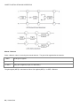
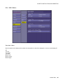
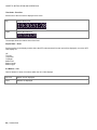
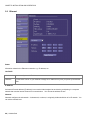
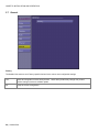
Kaleido-Solo 3G/HD/SD SDI to HDMI Converter Guide to Installation and Operation M865-9900-204 08 February 2011 Miranda Technologies Inc. 3499 Douglas-B.-Floreani St-Laurent, Québec, Canada H4S 2C6 Tel. 514-333-1772 Fax. 514-333-9828 www.miranda.com © 2011 Miranda Technologies Inc. GUIDE TO INSTALLATION AND OPERATION Safety Compliance The power supply of this equipment complies with the following standards: UL 60950-1, 1st Edition, Safety for information technology equipment . CSA C22.2 No. 60950-1-03, 1st Edition, Safety for information technology equipment . Electromagnetic Compatibility This equipment has been tested for verification of compliance with FCC Part 15, Subpart B requirements for Class A digital devices. NOTE: This equipment has been tested and found to comply with the limits for a Class A digital device, pursuant to part 15 of the FCC Rules. These limits are designed to provide reasonable protection against harmful interference when the equipment is operated in a commercial environment. This equipment generates, uses, and can radiate radio frequency energy and, if not installed and used in accordance with the instruction manual, may cause harmful interference to radio communications. Operation of this equipment in a residential area is likely to cause harmful interference in which case the user will be required to correct the interference at his own expense. This equipment has been tested and found to comply with the requirements of the EMC directive 2004/108/CE: EN 55022 Class A radiated and conducted emissions EN 61000-4-2 Electrostatic discharge immunity EN 61000-4-3 Radiated electromagnetic field immunity – RF EN 61000-4-8 Power frequency magnetic field immunity EN 61000-4-11 Voltage dips, short-interruption and voltage variation immunity ENV 50204 Radiated EMF Immunity – RF 900 MHz pulsed How to contact us: For technical assistance, please contact the Miranda Technical support centre nearest you: Americas Telephone: +1-800-224-7882 e-mail: [email protected] Asia Telephone: +852-2539-6987 e-mail: [email protected] Europe, Middle East, Africa, UK Telephone: +44 (0) 1491 820222 e-mail: [email protected] China Telephone: +86-10-5873-1814 e-mail: [email protected] France (only) Telephone: +33 (0) 1 55 86 87 88 e-mail: [email protected] Visit our web site at www.miranda.com ii | Kaleido-Solo GUIDE TO INSTALLATION AND OPERATION Table of Contents 1. Kaleido-Solo 3G/HD/SD Video to HDMI Converter ................................................................. 1 1.1 1.2 1.3 1.4 2 Installation ................................................................................................................................ 4 2.1 2.2 2.3 3 Special button functions ...................................................................................................................... 8 Status LED .......................................................................................................................................... 8 Behavior ................................................................................................................................... 9 4.1 4.2 5 Unpacking ........................................................................................................................................... 4 Connector Panel ................................................................................................................................. 5 Powering up ........................................................................................................................................ 6 Operating Controls and Functions ......................................................................................... 7 3.1 3.2 4 Introduction ......................................................................................................................................... 1 Key features and benefits ................................................................................................................... 2 Block Diagram ..................................................................................................................................... 3 Output example ................................................................................................................................... 3 Video ................................................................................................................................................... 9 4.1.1 Supported input resolution ..................................................................................................... 9 4.1.2 Supported output resolution ................................................................................................. 10 4.1.3 Supported frame rate processing ........................................................................................ 10 4.1.4 Scaling limitations ................................................................................................................ 11 4.1.5 Processing delay .................................................................................................................. 11 Audio ................................................................................................................................................. 11 Configuration (Menu) ............................................................................................................. 12 5.1 5.2 5.3 5.4 5.5 5.6 5.7 5.8 5.9 Status Menu ...................................................................................................................................... 14 Video Menu ....................................................................................................................................... 15 Metadata Menu ................................................................................................................................. 18 Audio Menu ....................................................................................................................................... 21 5.4.1 Audio - General .................................................................................................................... 21 5.4.2 Audio - ALM ......................................................................................................................... 23 5.4.3 Audio - Downmix .................................................................................................................. 25 5.4.4 Audio - Loudness ................................................................................................................. 30 5.4.5 Audio - Loudness Advanced ................................................................................................ 32 5.4.6 Audio - Loudness Control .................................................................................................... 34 On Screen Display (OSD) Menu ....................................................................................................... 36 5.5.1 OSD - General ..................................................................................................................... 36 5.5.2 OSD - Loudness .................................................................................................................. 38 5.5.3 OSD - ALM ........................................................................................................................... 41 5.5.4 OSD - Others ....................................................................................................................... 45 Ethernet ............................................................................................................................................. 48 General ............................................................................................................................................. 50 About Menu ....................................................................................................................................... 51 Safe Mode ......................................................................................................................................... 52 6 7 Upgrade Procedure ................................................................................................................ 54 Specifications......................................................................................................................... 57 8 Annex 1: Glossary ................................................................................................................. 58 Kaleido-Solo | iii GUIDE TO INSTALLATION AND OPERATION 9 Annex 2: AFD Functions ....................................................................................................... 59 10 Annex 3: Installing the Optical Interface .............................................................................. 63 11 Annex 4: SFP module and description ................................................................................. 65 12 Annex 5: Mounting bracket ................................................................................................... 66 iv | Kaleido-Solo GUIDE TO INSTALLATION AND OPERATION 1. Kaleido-Solo 3G/HD/SD Video to HDMI Converter 1.1 Introduction Kaleido-Solo is a compact, standalone 3Gbps/HD/SD video to HDMI converter, which allows low cost LCD displays to be used for video and loudness/dialnorm monitoring. It‟s ideal for many professional monitoring applications, including production, mobile truck, post-production and broadcast. The converter allows operators to monitor loudness and dialnorm levels accurately over time, using an history graph overlay, without the cost and complexity of a traditional loudness monitoring device. Kaleido-Solo also provides overlays for markers, Time Code, dynamic UMD (Under Monitor Display), AFD and ALM (Audio Level Meters). To simplify embedded audio monitoring, it provides two audio connectors to output S/PDIF and analog stereo of a 5.1 downmix, or any audio pair. Kaleido-Solo provides automatic video input format detection, and supports a wide variety of video resolutions, including 525i, 625i, 720p, 1080i and 1080p. Kaleido-Solo is available in two versions: KS-900 and KS-910. These two versions are identical except that the KS900 does not offer loudness and dialnorm monitoring. Kaleido-Solo | 1 GUIDE TO INSTALLATION AND OPERATION 1.2 Key features and benefits 3Gbps/HD/SD to HDMI converter for video and audio monitoring Offers high quality and rich monitoring using a low-cost LCD panel Dual program loudness and dialnorm monitoring over time (KS-910 only) ATSC A/85 and EBU R128 loudness measurement modes (KS-910 only) Automatic input format detection Supports 525i, 625i, 720p, 1080i and 1080p video resolutions Multi frame rate support including 23.98p/PsF, 24p/PsF, 25p/PsF, 50i, 50p, 59.94i and 59.94p Built-in scaler/de-interlacer Optical SFP fiber input/output options S/PDIF digital audio terminal that can output either: o a 5.1 Downmix o any PCM stereo pair o an incoming Dolby Digital stream Analog audio terminal that can output either: o a 5.1 Downmix o any PCM stereo pair Selectable burn-in and Metadata overlay: o ALM (Audio Level Meters) o Aspect ratio markers o Time Code o AFD/WSS/VLI o Dynamic UMD (Under Monitor Display) o History graph of audio loudness levels and dialnorm Easy configuration using on-screen menus Failsafe mechanism for unsupported monitor resolutions Convenient mounting bracket included 2 | Kaleido-Solo GUIDE TO INSTALLATION AND OPERATION 1.3 Block Diagram The following block diagram shows the functionality of the Kaleido-Solo. Figure 1 - Functional Block Diagram 1.4 Output example Figure 2 - Elements of the on-screen display Kaleido-Solo | 3 GUIDE TO INSTALLATION AND OPERATION 2 Installation 2.1 Unpacking Make sure the following items have been shipped with your Kaleido-Solo. If any of the following items are missing, contact your distributor or Miranda Technologies Inc. Kaleido-Solo Power Supply Power cord User Manual Special mounting adapter with Kaleido-Solo mounting screws (see section 12) 4x square velcro Warranty and Support Contact 4 | Kaleido-Solo GUIDE TO INSTALLATION AND OPERATION 2.2 Connector Panel The rear connector panel incorporates all inputs and outputs associated with the Kaleido-Solo, with the exception of a Remote Control connector (currently unused and sold separately) on the front panel. 1 2 3 4 5 6 7 8 9 Connections # Label Signal Connector type 1 Fiber OUT/IN 2 3G/HD/SD IN SDI input BNC 3 3G/HD/SD OUT SDI output BNC 4 S/PDIF Audio Out S/PDIF digital 2 ch. 3.5mm stereo jack 5 ANALOG Audio Out 2 channels unbalanced 3.5mm stereo jack 6 Monitor Out HDMI to monitor HDMI type A 7 Ethernet 10/100 RJ-45 8 RS-422 / GPI RJ-45 9 Power SFP The two video outputs (fiber and electric) are not loop-throughs of their respective inputs. They both carry the video from the selected input of the Kaleido-Solo. In this sense, the Kaleido-Solo functions as an optical/electric or electric/optical converter. Kaleido-Solo | 5 GUIDE TO INSTALLATION AND OPERATION 2.3 Powering up When powering up the Kaleido-Solo The led should turn on red. After 5 seconds the led should flash red (no valid SDI input) or green (valid SDI input). Your monitor should turn on and you should see content of the SDI input. If you only use the optional optical input you won‟t be able to see any video until 15 seconds approximately. In this step Kaleido-Solo will use all factory default parameters for video and audio. Even if you had muted audio you will hear audio in this boot up step. After 15 seconds the led should stop blinking. The overlay should appear making the monitor turn off and on once. You are now ready to use the Kaleido-Solo. The average total time to power-up a Kaleido-Solo is 20 seconds. 6 | Kaleido-Solo GUIDE TO INSTALLATION AND OPERATION 3 Operating Controls and Functions The Kaleido-Solo is configured and operated using the four buttons on the front panel to navigate through on-screen menus displayed on the video monitor. There are also some non-menu functions for these buttons. From left to right: # Label Description 1 Reset button 2 Status Status LED 3 Remote control <Reserved for future use> 4 Escape 5 Up 6 Down 7 Enter Note that you can see 2 mounting holes on the right side to mount the included metal bracket - see section 12. Kaleido-Solo | 7 GUIDE TO INSTALLATION AND OPERATION 3.1 Special button functions Label Description Reset button Press to reset unit Hold for 5 seconds to restore factory default Hold for 5 seconds to enter safe mode (640x480) + Analog audio volume control (when not in menu) or 3.2 Status LED The status LED in the lower left corner of the front panel displays the current status of the Kaleido-Solo. Status Description Green Video presence on selected input with no errors Flashing green Kaleido-Solo is still booting up with a valid video input Red No signal Signal with errors Unstable input signal Flashing Red Kaleido-Solo is still booting up with an invalid video input Hardware failure (after boot up) Orange Internal built in test pattern enabled (only works with a valid input) Flashing Orange Safe mode selected 8 | Kaleido-Solo GUIDE TO INSTALLATION AND OPERATION 4 Behavior 4.1 Video 4.1.1 Supported input resolution Format Kaleido representation (status video menu) 525i 59.94 525 625i 50 625 1280x720p 60 720p 60Hz 1280x720p 59.94 720p 59.94Hz 1280x720p 50 720p 50Hz 1920x1080i 60 1080i 60Hz 1920x1080i 59.94 1080i 59.94Hz 1920x1080i 50 1080i 50Hz 1920x1080p 60 1080p 60Hz 1920x1080p 59.94 1080p 59.94Hz 1920x1080p 24 1080p 24Hz 1920x1080p 23.98 1080p 23.98Hz 1920x1080p 50 1080p 50Hz 1920x1080p 25 1080p 25Hz 1920x1080 PsF 24 1920x1080 PsF 24 1920x1080 PsF 23.98 1920x1080 PsF 23.98 1920x1080 PsF 25 1080i 50Hz Kaleido-Solo | 9 GUIDE TO INSTALLATION AND OPERATION 4.1.2 Supported output resolution Format Kaleido representation (status video menu) 1920x1200p 60/59.94/50 e.g.: 1920x1200p60 1920x1080p 60/59.94/50 e.g.: 1920x1080p60 1600x1200p 60/59.94/50 e.g. : 1600x1200p60 1680x1050p 60/59.94/50 e.g. : 1680x1050p60 1440x900p 60/59.94/50 e.g. : 1440x900p60 1366x768p 60/59.94/50 e.g.: 1366x768p60 640x480p 60/59.94 e.g.: 640x480p60 Note that 640x480p 60 is the safe mode resolution. 4.1.3 Supported frame rate processing Frame rate input 60/59.94/30/29.97/24/23.98 50/25 10 | Kaleido-Solo 60Hz monitor 50Hz monitor GUIDE TO INSTALLATION AND OPERATION Here is some example of frame rate conversion (the scaling processing has been omitted for brevity): Input Processing Output 1280x720p 59.94 No processing 1920x1200p 59.94 1920x1080i 60 Deinterlaced 1920x1200p 60 Frame doubling 625i 50 Deinterlaced 1920x1200p50 Frame doubling 625i 50 Deinterlaced 1920x1200p60 Frame repetition 1920x1080p24 Frame repetition (3:2 insertion) 1920x1200p60 1920x1080i50 Deinterlaced 1920x1200p50 (50i/PsF should be set to interlaced) Frame doubling 1920x1080 PsF 25 Field merge (50i/PsF should be set to PsF) Frame doubling 4.1.4 1920x1200p50 Scaling limitations When scaling an SD 4:3 input (e.g.: AFD Code: 4:3_8) to a 1920x1200 monitor the output image will not fill the monitor, a black border is added and the aspect ratio is still maintained. When scaling an SD letter box input (e.g.: AFD Code: 4:3_4) into a 1920x1200 or 1920x1080 monitor the output image will not fill the monitor as it should. The aspect ratio is still maintained. 4.1.5 Processing delay The Kaleido-Solo‟s video processing delay is about 1 frame when the input frame rate is equal to half of the output rate (e.g.: p60 to p60, i60 to p60). In all other cases the processing delay is kept at its minimum. 4.2 Audio Kaleido-Solo doesn‟t decode compressed audio. Selected compressed audio will be passed through HDMI and SPDIF interfaces unprocessed. Note that the monitor must support compressed audio if you pass compressed audio on the hdmi output. Kaleido-Solo | 11 GUIDE TO INSTALLATION AND OPERATION 5 Configuration (Menu) To open the menu system, push ENTER. The menu display will open in the center of the screen. The current position always appears to the right and it, as well as the path to it, is highlighted in yellow. Move up and down the options in the current level by using the UP and DOWN buttons Move back to the previous level on the left by pushing the ESCAPE button Move on to the next level, which will appear on the right, by pushing the ENTER button. 12 | Kaleido-Solo GUIDE TO INSTALLATION AND OPERATION The right-most level will usually be a level where a value or option must be selected. It will be a list of choices, or perhaps a sliding scale. When you enter that level, the current value will be shown Select a different value using the UP and DOWN buttons, then: Either...... Push ENTER to choose that value and then ESCAPE to move back to the previous menu level leaving the parameter unchanged. Or ......... Push ESCAPE to move back to the previous menu level while leaving the value unchanged When you have finished using the menu, push ESCAPE until you are in the left-most column, and then once more. The menu will disappear from the screen. Kaleido-Solo remembers the last path you used, so you can retrace your steps back to the last parameter changed quickly, just by pushing ENTER until you arrive at the value list. All parameters are saved automatically 5 seconds after the last change. Be sure to not unplug the Kaleido-Solo within this 5 seconds or you may lose your modifications. Note that these 5 seconds also apply when you reverse a change using the ESCAPE key. Kaleido-Solo | 13 GUIDE TO INSTALLATION AND OPERATION 5.1 Status Menu Category Video status Description Input Shows the selected input Electrical (BNC) / Optical (SFP module). Shows the format detected as specified in section 4.1.1. Audio status SFP Module Shows the type of external module detected and supported (RX, TX or RX-TX) see Annex 4: SFP module and description. Aspect Ratio Shows the AFD/VLI/WSS aspect ratio video processing applied at the output. This parameter can be changed in the Metadata section. Output Shows the format at the Kaleido-Solo‟s output. Monitor Shows the prefered monitor resolution detected by the Kaleido-Solo. 1 to 16 Shows the type of audio detected per channel (PCM, NPCM, AC3, DOLBY E or N/A). The Monitor resolution can be different than the Output resolution. In most cases both resolution will be the same. 14 | Kaleido-Solo GUIDE TO INSTALLATION AND OPERATION 5.2 Video Menu Input Selection Select the input signal to be used by the Kaleido-Solo. Choose between: Electrical: The signal arriving on the rear-panel BNC connector. Optical: The signal arriving via optical fiber into the SFP module installed in the rear panel. Scaler Auto: The scaler uses EDID data from the display (via the HDMI port) to determine the optimum image size for display. The input signal is de-interlaced and then scaled for the display. Off: The incoming image is not rescaled. If it is smaller than the display, it will appear centered within the display. If it is larger than the display, then it is aligned with the upper left corner of the display and cropped so that only a part of it is shown. In this mode the video will not react to the aspect ratio configuration. Kaleido-Solo | 15 GUIDE TO INSTALLATION AND OPERATION Picture Position This configuration is taken into account only when input vertical resolution does not fill the monitor vertical resolution. Center: The image will be centered vertically. Top: The image will start at the top. This will leave space at the bottom of the output video for UMD, time code, etc. Dynamic Range SDI video has a dynamic range from 16 for black to 235 for white. Dynamic range expansion broadens the range to the full gamut of 0 to 255 that is available in an 8-bit system. Expand: Use the full dynamic range of 0 to 255 for the displayed video by expanding the input video data (video processing implied). Video values lower than 16 will be clipped to 0. Standard: Display the video using the standard dynamic range of 16 to 235. Video values lower than 16 will be displayed properly. 50Hz i/PsF When the input signal is 1080i 50 Hz, it is not possible to automatically detect whether the video is 25 Hz PsF video or 50 Hz interlaced. If PsF is known to be present it must be manually selected, so that the Kaleido-Solo can properly process the video image (de-interlacing for interlaced video; field-merging for PsF video). Interlaced: Use when the input video is in interlaced format. The video will be de-interlaced. PsF: Use when the input video is in PsF format. The video will be field-merged. Test Pattern The user can replace the displayed video with a test signal (a valid input video signal must be present). Select from these choices: Off: The video appears at the output. Color Bars: Sends a 75% color bar test pattern (100% white), along with audio test tones (a continuous tone on right channel with pulsed tone on left channel in every pair) to the Kaleido-Solo output. Lip-sync: Sends a special test signal comprising color bars and tone plus a visual element that is used to align audio-video delays in a processing path. The special test signal consists of 75% color bars within which a white square is inserted every 4 seconds for a duration of 10 frames. Simultaneously with the beginning of the first field of video containing the white square, the audio channels at the output are pulsed with a tone lasting 250 ms. Viewing the video display and listening to the audio allows the user to time-align the audio and video for correct lipsync. Go to the Audio - General - Delay (SPDIF/Analog) menu (see section 5.4.1) to make the timing adjustment. 16 | Kaleido-Solo GUIDE TO INSTALLATION AND OPERATION Note that these test signals are available only when there is an input to the Kaleido-Solo, and they only appear on the HDMI and audio outputs; they do not appear on the BNC and optical outputs. Note that activating the test pattern will override all audio parameters e.g.: output volume. Aspect Ratio - Mode You cannot modify this selection. Forced: Selects the Forced HD selection (e.g.: 16:9_9) when an HD signal is present or the FORCED SD selection (e.g.: 4:3_8) to process (scale) the video accordingly. Aspect Ratio - Forced HD Select the AFD code that will be forced on the Kaleido-Solo output for HD input video signals when scaler is set to auto. Refer to: Annex 2: AFD Functions 16:9_2 16:9_3 ... 16:9_14 16:9_15 Aspect Ratio - Forced SD Select the AFD code that will be forced on the Kaleido-Solo output for SD input video signals when scaler is set to auto. Refer to: Annex 2: AFD Functions 4:3_2 4:3_3 .. 4:3_14 4:3_15 16:9_8 (Anamorphic) Kaleido-Solo | 17 GUIDE TO INSTALLATION AND OPERATION 5.3 Metadata Menu This menu is used to configure the parameters needed to correctly extract different metadata types - for example, the aspect ratio packet, time code packet or the Dolby metadata packet. Status Some statuses are reported directly in this menu for the ease of configuration. AR Status: Aspect ratio status shows the presence of an AFD code following the selected aspect ratio parameters (Detected or N/A). TC Status: Time code status shows the presence of time code (Detected or N/A). DM Status: Dolby metadata shows the presence of the selected SDID (Detected or N/A). 18 | Kaleido-Solo GUIDE TO INSTALLATION AND OPERATION Aspect ratio - AFD source Select the source of the metadata that will be used by this Kaleido-Solo for aspect ratio control: AFD: Selects AFD as the source for HD and SD (525, 625) aspect ratio descriptor. VLI: Selects VLI as the source for the SD (525, 625) aspect ratio descriptor. WSS: Selects WSS as the source for the SD (625) aspect ratio descriptor. The Active Format Descriptor (AFD) flag is used to identify the aspect ratio and protected areas of a video signal. The AFD flag is implemented differently in HD and SD: In HD, the AFD flag (SMPTE 2016) is sent as an ancillary packet, normally found on line 11 in the vertical ancillary space. In SD, the AFD flag is sent as a Video Line Index (VLI) signal (RP 186), as a Wide Screen Signaling (WSS) signal (ITU-R BT.1119-2) for 625 only, and as an AFD packet (SMPTE 2016). Note that it is not possible to specify different sources for SD and HD, e.g.: VLI for SD and AFD for HD. Time Code - SD Select Mode Select whether time code extraction from SD video inputs will be automatic or manual. Auto: The vertical interval of the incoming video is scanned and the first detected time code is extracted. Manual: Time code will only be extracted if it appears on a specified line in the vertical interval. In Manual mode only, the SD Select Line menu item is enabled, allowing the line number for extraction to be specified. Time Code - HD Select Type Select the source of the timecode to be displayed when the input video is HD. VITC: Use ATC VITC time code (time code updated every field). LTC: Use ATC LTC time code (time code updated every frame). Kaleido-Solo | 19 GUIDE TO INSTALLATION AND OPERATION Dolby Metadata – SDID Specify which SDID to look at for Dolby Metadata extraction: 01 02 ... 08 09 An SDI signal could contain up to 9 different Dolby metadata packets. This specifies which one to select. Some of the information contained in the selected packet could affect the behavior of the loudness (see section 0) or downmix (see section 0). 20 | Kaleido-Solo GUIDE TO INSTALLATION AND OPERATION 5.4 Audio Menu 5.4.1 Audio - General Output Selection Select the audio channel pair that will be sent to the Kaleido-Solo outputs (HDMI, S/PDIF and analog) for monitoring. Ch. 1-2 Monitor channel 1 (left) and 2 (right). ... Ch. 15-16 Monitor channel 15 (left) and 16 (right). Downmix Monitor the downmix output. See section 5.4.3 to configure the downmix channel assignment. OFF (MUTE) Turn off audio monitoring. Kaleido-Solo | 21 GUIDE TO INSTALLATION AND OPERATION The OSD ALMs indicate which audio pair is being monitored. A grey marker at the bottom of the ALM shows the selected pair. In this example the audio pair 1-2 is selected. If downmix or off is selected no grey marker is present. Audio HDMI Choose whether to send the audio channels selected for monitoring to the HDMI port. On Enable audio insertion in HDMI. Off Disable audio insertion in HDMI (this could help with some monitors that does not support compressed audio). Volume (Analog) Adjust the volume of the Kaleido-Solo‟s analog audio output. 0 dB The input level is unchanged. ... -96 dB The input level is attenuated. Note that the audio output volume can also be adjusted by pressing the UP and DOWN keys when you are in normal operation (i.e. menu not displayed). Delay (SPDIF/Analog) Delay can be added to the SPDIF and analog audio outputs, to compensate for a monitor video delay, so that the audio timing can be matched to the video for lip sync. This control does not affect the audio inserted in the HDMI port. Using the lip sync test signal (see section 5.2) will help when making this adjustment. From the Delay (SPDIF/Analog) menu, press ENTER. The main menu disappears and only the adjustment slider remains visible. This ensures that the test signal or video that is being used to adjust the audio delay is not obscured by the menu. Use the UP and DOWN buttons to adjust the audio delay until the timing is subjectively correct, then press ESCAPE to go back to the Audio General menu. The available delay range is 0 to 120 ms. 22 | Kaleido-Solo GUIDE TO INSTALLATION AND OPERATION Audio in dBU level at 0 dBFS This configuration is used when using analog level meters (listed below). Furthermore, it‟s the reference level used to convert dBFS to dBU. Analog level meters affected by this parameter: BARGRAPH_VU_METER (IEC60268-17) Analog VU BARGRAPH_UK_PPM (IEC60268-10 type IIa) Analog peak BARGRAPH_EBU_PPM (IEC60268-10 type IIb) Analog peak BARGRAPH_NORDIC_PPM (IEC60268-10 type I) Analog peak BARGRAPH_DIN_PPM (IEC60268-10) Analog peak 5.4.2 Audio - ALM True Peak Mode Checked All ALMs are in true peak mode (as explained in document ITU-R BS.1770-1 annex 2). Unchecked All ALMs are in standard mode. Kaleido-Solo | 23 GUIDE TO INSTALLATION AND OPERATION 5.1 Assignment No.1 Select the channels you want to assign to the first (leftmost) 5.1 ALM. To see this 5.1 ALM you must enable it - see section 5.5.3. 5.1 Assignation No.2 Select the channels you want to assign to the second (rightmost) 5.1 ALM. To see this 5.1 ALM you must enable it see section 5.5.3. Stereo Assignment Select input channels (by pair) for each of the eight available ALMs. 24 | Kaleido-Solo GUIDE TO INSTALLATION AND OPERATION 5.4.3 Audio - Downmix The Kaleido-Solo provides two channels of audio output. If the input audio is a 5.1 surround sound signal, it must be downmixed for monitoring. This menu provides the configuration for the downmix. Control - Operation Mode Manual Choose this option if you want to manually configure the channels for the downmix (see audio -> downmix -> input selection). Follow Metada If you have properly configured the dolby metadata extraction (see section 0) you can use this option. It will configure the downmix using specific extracted parameters from program 1 (center mix level, surround mix level and mode (LtRt/LoRo)). If you also want to use the dialnorm extracted parameter you must set the “Apply Dialnorm” selection to ON. You can display the contents of the Dolby metadata using the Show Status menu (see section 5.1). Note that if there is no Dolby metadata and the operation mode is set to “follow metadata” the KaleidoSolo will switch to manual mode automatically using entered manual settings for its processing. If Dolby metadata is detected again the Kaleido-Solo will switch back to follow metadata mode. Kaleido-Solo | 25 GUIDE TO INSTALLATION AND OPERATION Control - Normalization Select whether level and loudness normalization are applied to the downmix results Off Downmix output level is not normalized. Clipping may occur depending on the input channel levels and the selected mix levels. Level A (lvl) Downmix output level is normalized based on the applied mix levels to provide a uniform output over the range of mix levels available. Clipping will never occur, even with full scale input channels and mix levels. Level B (lvl+loud) Downmix output level is normalized based on the channel configuration to provide a uniform output loudness between 3/2 and 2/0 programs. Downmixing a 3/2 program produces a loudness attenuation compared to the same program in 2/0 at the same input loudness. To provide a uniform output loudness, a loudness attenuation is applied only on 2/0 programs. If the operating mode is Follow Metadata, the channel configuration is given by the AC-3 coding mode parameter in the metadata. If the operating mode is Manual, the channel configuration is given by the selected mix levels: a 2/0 channel configuration is achieved by setting Center, Surround, and LFE Mix Levels to Mute. Any other combination of mix levels is assumed to be a 3/2 channel configuration. Level-B normalization also includes Level-A normalization, based on the applied mix levels. Clipping will never occur, even with full scale input channels and mix levels. Control - LFE Mix Level Set the level of the contribution of the LFE channel to the downmixed signal. +10 dB +9 dB +7.5 dB +6 dB The input level is boosted. +4.5 dB +3 dB +1.5 dB 0 dB The input level is unchanged. -1.5 dB -3 dB -4.5 dB The input level is reduced. -6 dB Mute LFE is not used in the downmix. This gain is always applied to LFE even if the operation mode is set to follow metadata because there is no such information in the metadata. 26 | Kaleido-Solo GUIDE TO INSTALLATION AND OPERATION Dolby Metadata - Show Status Select Show Status and ENTER to see the contents of the Dolby Metadata that will control the downmix process in the Follow Metadata operating mode. The Dolby Status information window opens, as shown in this example - Push ESCAPE to close the information window and return to the menu. Dolby Metadata - Apply Dialnorm Choose whether to apply the Dialnorm parameter to the downmixed stereo program. On Applies a gain after the downmix. The gain applied is contained in the Dolby Metadata if the operation mode is set to follow metadata or set by the manual dialnorm if operation mode is set to manual. The -31 dBFS is equal to unity (no gain). Off No gain applied. Manual – Mode LtRt Stands for Left total/Right total. It‟s a downmix suitable for decoding with a Dolby Pro Logic surround sound device. LoRo Stands for Left only/Right only. It‟s a downmix suitable for stereophonic sound playback. Kaleido-Solo | 27 GUIDE TO INSTALLATION AND OPERATION Manual - Dialnorm Select a dialnorm value to use during the manual downmix. The gain will be applied after the downmix. -1 dBFS 30 dB gain is applied. ... -31 dBFS Unity gain is applied (no gain, no attenuation). The gain applied (dBFS) is calculated as follow: Gain applied (dBFS) = 31 dBFS + Dialnorm 28 | Kaleido-Solo GUIDE TO INSTALLATION AND OPERATION Manual - Center Mix Level Select the mix level of the center channel into the stereo downmix. +3 dB +1.5 dB 0 dB The input level is boosted. The input level is unchanged. -1.5 dB -3 dB -4.5 dB The input level is reduced. -6 dB Mute Center is not used in the downmix. Manual - Surround Mix Level Select the mix level of the surround channels into the stereo downmix. +3 dB +1.5 dB 0 dB The input level is boosted. The input level is unchanged. -1.5 dB -3 dB -4.5 dB The input level is reduced. -6 dB Mute Surround is not used in the downmix. Input Selection Assign input channels to the L, R, C, LFE, Ls and Rs downmix inputs. Note that if compressed audio is detected on one or more of the assigned channels, the downmix audio will be muted. Kaleido-Solo | 29 GUIDE TO INSTALLATION AND OPERATION 5.4.4 Audio - Loudness Loudness measurement is available in Kaleido-Solo model 910 only. st nd The Kaleido-Solo supports two independent loudness measurements, called “1 Loudness” and “2 Loudness”. You can configure both in this menu. Having two separate measurements is useful if, for example, you want to measure one 5.1 and one stereo pair simultaneously. 1st Loudness/2nd Loudness - Program Selection Manual Use to manually set the coding mode and the channel selection. Prog. 1 Use the Dolby metadata contained coding mode and channel selection of program #1. ... Prog. 8 Use the Dolby metadata contained coding mode and channel selection of program #8. Note that loudness meters can, under some conditions, be unable to display loudness information. For instance, if one of the loudness audio channels involved is not PCM, an error message will be displayed and no loudness data will be shown. The same thing will happen if the audio program selected (and its associated audio coding mode) is extracted from Dolby Metadata and none can be found on input. An error message saying “no Dolby” will show up to explain why no data is being processed. 30 | Kaleido-Solo GUIDE TO INSTALLATION AND OPERATION 1st Loudness/2nd Loudness – Manual Coding Mode The manual coding mode offers a way to manually configure the loudness measurement. Changing the coding mode will enable or disable channel assignment. For example if you select 1/0 (c), only the center channel can be assigned and be considered in the loudness measurement. Here is a list of available coding modes: 1/0 (C) 2/0 (L, R) 3/0 (L, C, R) 3.0L (L, C, R, LFE) 2/1 (L, R, S) 2/1L (L, R, S, LFE) 3/1 (L, C, R, S) 3/1L (L, C, R, S, LFE) 2/2 (L, R, Ls, Rs) 2/2L (L, R, Ls, Rs, LFE) 3/2 (L, C, R, Ls, Rs) 3/2L (L, C, R, Ls, Rs, LFE) 1st Loudness/2nd Loudness - Target Src (Dialnorm) Manual By selecting this option you can change the loudness chart target in the loudness advance menu (Loud. Adv - see section 5.4.5). Follow Metada The loudness chart target is defined within the extracted Dolby metadata program (Loudness program settings - see section 0). 1st Loudness/2nd Loudness - Input Selection You can manually assign a physical channel to each available loudness input position, if the program selection is set to manual and the coding mode permits the position assignment. A coding mode 2/0 (L, R) will only permit channels to be assigned to the L and R positions. A coding mode 1/0 (C) will only permit a channel to be assigned to the C position. Note that you cannot assign the same channel twice. Kaleido-Solo | 31 GUIDE TO INSTALLATION AND OPERATION 5.4.5 Audio - Loudness Advanced 1st Loudness/2nd Loudness - EBU Mode Checked The loudness chart will follow the EBU R128 recommendation for the loudness measurement. Unchecked A parameter that is not compliant with EBU R128 has been changed (e.g.: Target parameter is not set to -23). Note that if there are stars in front of the menu name (e.g.: ** EBU Mode) it means that the measurement respects the EBU mode except the parameter or parameters that were manually changed that could affect the results. 32 | Kaleido-Solo GUIDE TO INSTALLATION AND OPERATION 1st Loudness/2nd Loudness - A-85 Mode Checked The loudness chart will follow the ATSC A/85 recommendation for the loudness measurement. Unchecked A parameter that is not compliant with ATSC A/85 has been changed (e.g.: Target parameter is not set to -24). Note that if there are stars in front of the menu name (e.g.: ** A-85 Mode) it means that the measurement respects the EBU mode except the parameter or parameters that were manually changed that could affect the results. 1st Loudness/2nd Loudness - Target This parameter will change the target value in loudness chart. Altering this value will unchecked the EBU or A-85 Mode. 1st Loudness/2nd Loudness - Short-Term Time Window Changing this parameter affects the short term calculation. The choices are: 1 sec .. 15 sec Loudness measurement summary Mode Momentary Short Term Integrated Gate Target Range EBU 400ms sliding window 3 sec sliding window infinite sliding window affecting integrated measure -23 dBFS yes A-85 400 ms sliding window 10 sec sliding window infinite sliding window none -24 dBFS no Refer to EBU R128 or ATSC A/85 specification for more specific details. Kaleido-Solo | 33 GUIDE TO INSTALLATION AND OPERATION 5.4.6 Audio - Loudness Control 1st Loudness/2nd Loudness - Meter Paused Force loudness chart 1 and/or 2 to pause. When paused, the loudness chart will display “pause” and last data will stay on screen. Running When loudness engine goes from a paused state to a running state, the engine is restarted and continues where it was left. A special case occurs for EBU LRA measurements that need valid short term values - no new LRA measurements will be displayed until the “Short-Term Time Window” has elapsed (e.g.: For EBU mode, this value is 3 sec). 1st Loudness/2nd Loudness - Reset Ok Reset all loudness measurements - traces on the loudness (1 or 2) chart. Cancel Return to the menu without any alteration. 34 | Kaleido-Solo GUIDE TO INSTALLATION AND OPERATION All - Meter Paused Force both loudness charts 1 and 2 to pause. Running Force both loudness charts 1 and 2 to run. All - Reset Ok Loudness engine is reset, past infinite integration is lost and measurement will start from scratch. Cancel Return to the menu without any alteration. Kaleido-Solo | 35 GUIDE TO INSTALLATION AND OPERATION 5.5 5.5.1 On Screen Display (OSD) Menu OSD - General Transparency Affects all OSD elements except the menu 5: Transparent ... 0: Opaque 36 | Kaleido-Solo GUIDE TO INSTALLATION AND OPERATION Show OSD Acts as a Master Switch affecting all OSD elements except the menu Checked: Enable the display of OSD elements. Each OSD element has its own show/hide parameter e.g.: loudness chart. Unchecked: Disable all OSD elements, irrespective of their individual Show/Hide setting. Note that if the OSD is turned off the video signal is still displayed. Kaleido-Solo | 37 GUIDE TO INSTALLATION AND OPERATION 5.5.2 OSD - Loudness Loudness measurement is available in Kaleido-Solo model 910 only. This menu controls the appearance of the on-screen loudness chart. Loudness 1/Loudness 2 Checked Display the (1 or 2) loudness chart. Unchecked Hide the (1 or 2) loudness chart. All the processing still continues even throught the chart is hidden. Position Move both loudness charts to the desired position on the screen: Top Left Top Center Top Right Bottom Left Bottom Center Bottom Right 38 | Kaleido-Solo GUIDE TO INSTALLATION AND OPERATION Chart Time Scale Set the horizontal time scale of the histogram to the desired duration: 20 Sec 2 Min 5 Min 10 Min 15 Min 30 Min Short Term Checked Display the short term trace in both loudness charts. Unchecked Hide the short term trace in both loudness charts. Integrated Checked Display the integrated trace in both loudness charts. Unchecked Hide the integrated trace in both loudness charts. Target (Dialnorm) Checked Display the target trace in both loudness charts. Unchecked Hide the target trace in both loudness charts. Display +9 Both loudness charts will use a scale of -41.0 LUFS/LKFS to -14.0 LUFS/LKFS (-18.0 LU/dB to +9.0 LU/dB). +18 Both loudness charts will use a scale of -59.0 LUFS/LKFS to -5.0 LUFS/LKFS) (-36.0 LU/dB to +18.0 LU/dB). Compact Display the compact form of both loudness charts. The compact form includes the momentary meter and measurement summary. In this case the momentary meter will use the +9 scale. Kaleido-Solo | 39 GUIDE TO INSTALLATION AND OPERATION Loudness chart (full) The color identifies the traces (center section) with their numeric values (left section). Left section Refer to EBU R128 or ATSC A/85 specification for more details. Center section Graphic representation of short term, integrated measurement and the target value. The time scale is represented at the bottom of this section. Those traces can be independently shown or hidden (see section 0). The “EBU Mode or A85 Mode” is displayed only when the measurements are compliant to those specifications (see section 5.4.5). Right section Meter that represents the momentary measurement. Loudness chart (compact) The compact form is represented by the left section of the full loudness chart combined with the momentary meter. Note that the momentary scale in compact mode is fixed to +9. 40 | Kaleido-Solo GUIDE TO INSTALLATION AND OPERATION 5.5.3 OSD - ALM This menu sets up the appearance of the on-screen Audio Level Meters. Control - On Screen Show ALM Choose whether to display the on-screen ALMs: Checked Show all audio level meters. Unchecked Hide all audio level meters. Control - Scale Checked Show scales on all audio level meters - levels are in dB. Unchecked Hide scales on all audio level meters. Control - Channel ID Checked Show the identity (channel numbers) on all audio level meters. Unchecked Show the identity (channel numbers) on all audio level meters. Kaleido-Solo | 41 GUIDE TO INSTALLATION AND OPERATION ALM Standard – ALM 5.1 (1 and 2) Off Hide the 5.1 audio level meters giving the space to show up to 3 stereo audio level meters. Other types See ALM1,2,etc type for more details. ALM Standard - ALM1, ALM2, etc. For each of the eight available ALMs, Off Hide the stereo meter. Other types See next picture and next table to see all representation supported. 1 Linear (Digital type VU (Green bars) + Peak (White horizontal lines)) 2 EBU Digital (Digital type VU (Green bars) + Peak (White horizontal lines)) (IEC60268-18) 3 VU Meter (Analog VU) (IEC60268-17) 4 UK PPM (Analog peak) (IEC60268-10 type IIa) 5 EBU PPM (Analog peak) (IEC60268-10 type IIb) 6 Nordic PPM (Analog peak) (IEC60268-10 type I) 7 DIN PPM (Analog peak) (IEC60268-10) 42 | Kaleido-Solo GUIDE TO INSTALLATION AND OPERATION Note that the numbers 1 to 7 on black background (image bottom numbers) are just here for the purpose of the manual and cannot be displayed on the video output of the Kaleido-Solo. Scale Scale is the graduation in dB of an audio level meter. Channel ID Identifies the audio channel pair reprensented by audio level meter. Phase meter Provides an indication of the relative phase of the two channels and thereby provides some measure of mono compatibility. The range is 0 to 180 degrees and is represented as follows: bottom is 0 degrees and top is 180 degrees. Kaleido-Solo | 43 GUIDE TO INSTALLATION AND OPERATION 5.1 channel assignment L Stands for front left C Stands for center R Stands for front right LS Stands for left surround LF Stands for subwoofer RS Stands for right surround 44 | Kaleido-Solo GUIDE TO INSTALLATION AND OPERATION 5.5.4 OSD - Others Time Code - Show Set the location on the display monitor where the extracted time code will be displayed, or turn time code display off. Off Top Left Top Center Top Right Bottom Left Bottom Center Bottom Right Kaleido-Solo | 45 GUIDE TO INSTALLATION AND OPERATION Time Code - Font Size Set the size of the font used to display the time code: Big Selects the big font Small Selects the small font The samples show the relative sizes of the fonts. Aspect Ratio – Show Set the location on the display monitor where the AFD code extracted from the input will be displayed, or turn the AFD code display off: Off Top Left Top Center Top Right Bottom Left Bottom Center Bottom Right 4:3 Markers - Line Choose whether to show 4:3 markers within the 16:9 video displays No Lines Marker are not displayed. Lines Markers are displayed. 46 | Kaleido-Solo GUIDE TO INSTALLATION AND OPERATION 4:3 Markers - Mask The area of the image that is outside the protected area as shown by the markers can be masked, and the mask selected as transparent or opaque, using this menu. Off No mask applied. Opaque Mask is applied and completely blocks video. Transparent Mask is applied and video can be seen through mask. The 4:3 line or mask will appear only when the active output resolution is 16:9 (e.g.: 1920x1080p60). For this behavior the 4:3 line/4:3 mask must not be set to off. Under monitor display (UMD) Dynamic text can be driven by some automation systems. Note that the ID number for the Kaleido-Solo UMD text box is „0‟ and the port number is „13000‟. This is useful when configuring the third-party automation system. Kaleido-Solo | 47 GUIDE TO INSTALLATION AND OPERATION 5.6 Ethernet Status Information related to the Ethernet connection e.g.: IP address, etc. Use DHCP Unchecked: Use manually-entered IP address. Checked: Let the DHCP server on your network to assign an IP address every time you power-up the KaleidoSolo. IP Address An Internet Protocol address (IP address) is a numerical label assigned to each device participating in a computer network that uses the Internet Protocol for communication. You can set the address IP here. Netmask Netmask configures the subnetwork. A subnetwork, or subnet, is a logically visible subdivision of an IP network. You can set the netmask here. 48 | Kaleido-Solo GUIDE TO INSTALLATION AND OPERATION Gateway A network node equipped for interfacing with another network that uses different protocols if needed. You can put the IP address of a gateway here. Apply Settings After IP, Netmask and Gateway addresses are entered, navigate to the “Apply Settings” button and click on it. Wait few seconds to see the Status box information change accordingly. If DHCP is checked, the IP is the one provided by your network DHCP server. Kaleido-Solo | 49 GUIDE TO INSTALLATION AND OPERATION 5.7 General Factory The Kaleido-Solo stores a set of factory-specified values for the various user-configurable settings Yes: Reset all configuration to their factory default. Those factory default may change over product version changes such as a software update. No: Keep the current configuration. 50 | Kaleido-Solo GUIDE TO INSTALLATION AND OPERATION 5.8 About Menu This screen identifies this specific Kaleido-Solo‟s model and version number. This information will be required if you need assistance from Miranda technical support. There are other elements on this page labeled B, C, F and M that could be needed by the Miranda technical support. Kaleido-Solo | 51 GUIDE TO INSTALLATION AND OPERATION 5.9 Safe Mode Safe mode is a specialized operating mode designed to allow the user to force an HDMI resolution. This can be used if the monitor's preferred resolution is not supported or if the monitor has a corrupted EDID (no valid preferred resolution information). To enter the Safe mode, push ESCAPE and DOWN together and hold for 5 seconds. The Kaleido-Solo will configure with an output of 640x480p60 if no or 50Hz video input is detected. If 59.94Hz is detected the safe mode resolution will be 640x480p59.94. 640x480 is chosen to be almost universally accepted by video monitors The Safe Mode Menu will be shown on the screen, allowing some operating parameters of the Kaleido-Solo to be set manually. Resolution The Output resolution of the Kaleido-Solo can be set to one of the following fixed values, or it can be set to follow the EDID from the monitor. EDID: Follow the prefered monitor resolution every time (power-up or connect a new monitor). 1920x1080p Force a 1920x1080p resolution every time (power-up or connect a new monitor). ... 640x480p Force a 640x480p resolution every time (power-up or connect a new monitor). 52 | Kaleido-Solo GUIDE TO INSTALLATION AND OPERATION Frame Rate Choose the frame rate of the output video. This option can be selected only if the resolution is not set to EDID. 50 Hz 60 Hz Apply Push ENTER to apply the settings made in this menu and close the menu. At the bottom of the menu, the resolutions of the selected input, the current output, and the monitor display as derived from the EDID are shown. Kaleido-Solo | 53 GUIDE TO INSTALLATION AND OPERATION 6 Upgrade Procedure When it becomes necessary to upgrade the Kaleido-Solo to a new software or firmware version, use the procedure described here. The Kaleido-Solo serves a web page that is the portal for upgrading the device. Use a web browser to access the IP address of the Kaleido-Solo that is to be upgraded. The current address is always found on the About menu (see section 5.1). The Kaleido-Solo is shipped with its IP address set to 192.168.3.31 Once you have accessed the Kaleido-Solo, the Introduction page appears in your browser window. Click on the Upgrade page here link to open the Tools | Upgrade Kaleido Solo page. Click on the Browse button to open the Choose File to Upload window where you can search your local computer or network for the upgrade file, which you should previously have obtained from Miranda. 54 | Kaleido-Solo GUIDE TO INSTALLATION AND OPERATION Select the file and click Open. The file name will appear in the Please Specify the Upgrade File data box, and the Upgrade button will be enabled. Click the Upgrade button to begin the upgrade procedure. A pop-up warning will appear, listing things you should NOT do while the Kaleido-Solo is upgrading: When you are ready to proceed, click OK. The main window will show that the upgrade is in progress, and remind you of the things NOT to do. Kaleido-Solo | 55 GUIDE TO INSTALLATION AND OPERATION When the upgrade is complete, the main window will notify you that it was successful, and advise you to reboot your Kaleido-Solo. Reboot the Kaleido-Solo to put the upgraded software into service. 56 | Kaleido-Solo GUIDE TO INSTALLATION AND OPERATION 7 Specifications VIDEO INPUT Signal: SMPTE-259M-C (270 Mbps) SMPTE-272M-C (270 Mbps with embedded audio) SMPTE-292M, SMPTE-299M (HD: 1.485, 1.485/1.001 Gbps) SMPTE-425 (2.970, 2.970/1.001 Gbps) Supported formats: SD: 480i59.94, 576i50 HD: SMPTE-274M: 1080i 50, 59.94, 1080p/PsF 23.98, 24, 25 HD: SMPTE-296M: 720p 50, 59.94 3G: SMPTE-425 level A (mapping 1): 1080p 50, 59.94 3G: SMPTE-425 level B: 1080p 50, 59.94 Cable length: 240 m Belden 1694A at 270 Mbps 150 m Belden 1694A at 1.485 Gbps 120 m Belden 1694A at 2.97 Gbps Return loss: >15 dB up to 1.5 GHz >10 dB up to 3 GHz Jitter: HD/SD: <0.2 UI 3Gbps: <0.3 UI FIBER I/O SMPTE 297M-2006 compliant Single receive or transmit or receive/transmit SFP module Dual receive or transmit modules can be installed, but only one Rx or Tx channel will be used HDMI OUTPUT Connector: Standard: Format: HDMI Type A HDMI 1.3a Compliant to EIA/CEA-861-D ANALOGIC AUDIO OUTPUT Connector: Signal: Level: Impedance: 3.5 mm stereo Jack 2 channels unbalanced analog audio +6.5 dBu 50 ohm SPDIF Connector: Signal: Level: Impedance: Sampling rate: 3.5 mm stereo Jack IEC 60958 0.5 Vp-p ±20% 75 ohm unbalanced 48 kHz ETHERNET Connector: RJ-45 PROCESSING Signal path: Processing delay: 8 bits 1 frame ELECTRICAL Voltage range: Power: 6 to 17 VDC 10 W Kaleido-Solo | 57 GUIDE TO INSTALLATION AND OPERATION 8 Annex 1: Glossary Concept Description EBU R128 Refer to EBU technical document 3341 ATSC A/85 Refer to document number: ITU-R BS.1770 58 | Kaleido-Solo GUIDE TO INSTALLATION AND OPERATION 9 Annex 2: AFD Functions The charts below show the conversions that will be performed by the Kaleido-Solo by selecting the Active Format Descriptor (AFD). In the images shown in the chart: BLACK Indicates that this portion of the transmitted image will be black GREY indicates Protected Area, consisting of picture content which may be cropped for optimum display on screens with a different aspect ratio. Input signal 4:3 monitor Output signal 16:9 monitor 16:9 Letterbox (top) image in a 4:3 frame 16:9 Letterbox (top) image in a 4:3 frame 16:9 Full frame image in a 16:9 frame (4:3_2) 14:9 Letterbox (top) image in a 4:3 frame (4:3_2) 14:9 Letterbox (top) image in a 4:3 frame (16:9_8) 14:9 Pillar-box image in a 16:9 frame (4:3_3) > 16:9 Letterbox (center) image in a 4:3 frame (4:3_3) > 16:9 Letterbox (center) image in a 4:3 frame (16:9_11) > 16:9 Letterbox (center) image in a 16:9 frame (4:3_4) 4:3 Full frame image in a 4:3 frame (4:3_4) 4:3 Full frame image in a 4:3 frame (16:9_4) 4:3 Pillar-box image in 16:9 frame (4:3_8) 4:3 Full frame image in a 4:3 frame (use preferred 4:3_8 code instead) (4:3_8) 4:3 Full frame image in a 4:3 frame (16:9_9) 4:3 Pillar-box image in 16:9 frame (4:3_9) (16:9_9) (4:3_9) Kaleido-Solo | 59 GUIDE TO INSTALLATION AND OPERATION Input signal 4:3 monitor Output signal 16:9 monitor 16:9 Letterbox image in 4:3 frame 16:9 Letterbox image in 4:3 frame (4:3_10) 14:9 Letterbox image in a 4:3 frame 14:9 Letterbox image in a 4:3 frame (4:3_11) 4:3 Image shoot and protect 14:9 in a 4:3 frame (4:3_11) 4:3 Image shoot and protect 14:9 in a 4:3 frame (16:9_11) 14:9 Pillar-box image in a 16:9 frame (4:3_13) 16:9 Letterbox image shoot and protect 14:9 in a 4:3 frame (4:3_13) 16:9 Letterbox image shoot and protect 14:9 in a 4:3 frame ( 16:9_11) 16:9 Image shoot and protect 14:9 in a 16:9 frame (4:3_14) 16:9 Letterbox image shoot and protect 16:9 in a 4:3 frame (4:3_14) 16:9 Letterbox image shoot and protect 16:9 in a 4:3 frame (16:9_14) 16:9 Image shoot and protect 14:9 in a 16:9 frame (4:3_15) 16:9 image shoot and protect 16:9 in a 4:3 frame (anamorphic) (4:3_15) 16:9 image shoot and protect 16:9 in a 4:3 frame (anamorphic) (16:9_15) 16:9 Full frame image in a 16:9 frame (16:9_8) (16:9_8) 60 | Kaleido-Solo (4:3_10) 16:9 Full frame image in a 16:9 frame (16:9_8) 14:9 Pillar-box image in a 16:9 frame (16:9_8) GUIDE TO INSTALLATION AND OPERATION Input signal 4:3 monitor Output signal 16:9 monitor 16:9 Full frame image in a 16:9 frame (use preferred 16:9_8 flag instead) 16:9 Letterbox image in 4:3 frame 16:9 Full frame image in a 16:9 frame (16:9_2) 14:9 Pillar-box image in a 16:9 frame (use preferred 16:9_11 flag instead) (4:3_10) 14:9 Letterbox image in a 4:3 frame (16:9_2) 14:9 Pillar-box image in a 16:9 frame (16:9_3) > 16:9 Letterbox (center) image in a 16:9 frame (4:3_11) 16:9 Letterbox image in 4:3 frame (16:9_3) 16:9 Protected Full frame image in a 16:9 frame (16:9_4) 16:9 Full frame image in a 16:9 frame (4:3_4) 16:9 Letterbox image in 4:3 frame (16:9_4 16:9 Full frame image in a 16:9 frame (16:9_8) 4:3 Pillar-box image in 16:9 frame (16:9_9) 16:9 Protected Full frame image in a 16:9 frame (16:9_10) (4:3_10) as shown here, or (4:3_8) as in box below 4:3 Full frame image in a 4:3 frame (4:3_8) 16:9 Letterbox image in 4:3 frame (4:3_10) (16:9_8) 4:3 Pillar-box image in 16:9 frame (16:9_9) 16:9 Protected Full frame image in a 16:9 frame (16:9_10) Kaleido-Solo | 61 GUIDE TO INSTALLATION AND OPERATION Input signal 4:3 monitor Output signal 16:9 monitor 14:9 Pillar-box image in a 16:9 frame 14:9 Letterbox image in a 4:3 frame 14:9 Pillar-box image in a 16:9 frame (16:9_11) 4:3 Pillar-box image Shoot and protect 14:9 in a 16:9 frame (4:3_11) 4:3 Image shoot and protect 14:9 in a 4:3 frame (16:9_11) 14:9 Pillar-box image in a 16:9 frame (16:9_13) 16:9 Image shoot and protect 14:9 in a 16:9 frame (4:3_13) 14:9 Letterbox image in a 4:3 frame (16:9_11) 16:9 Image shoot and protect 14:9 in a 16:9 frame (16:9_14) 16:9 Image shoot and protect 4:3 in a 16:9 frame (4:3_11) 4:3 Full frame image in a 4:3 frame (16:9_14) 16:9 Image shoot and protect 4:3 in a 16:9 frame (16:9_15) 62 | Kaleido-Solo (4:3_8) (16:9_15) GUIDE TO INSTALLATION AND OPERATION 10 Annex 3: Installing the Optical Interface Installing and removing the Fiber I/O interface cartridge requires special care. This annex describes the process. The interface consists of two parts: A socket on the rear panel into which an SFP interface module is plugged An SFP (Small Form-factor Pluggable) module into which the optical fibers are plugged, and which incorporates the optical/electrical interface Cautions and Warnings SFP Transmitter modules contain a class 1 laser, which emits invisible radiation whenever the module is powered up. Because the SFP is hot-swappable, the module may be powered up as soon as it is installed. DO NOT LOOK INTO AN OPERATING SFP MODULE’S CONNECTORS, AS EYE DAMAGE MAY RESULT. The SFP module is sensitive to electrostatic discharge (ESD). SFP modules are subject to wear, and their useful lifetime is reduced each time they are inserted or removed. Do not remove them more often than is absolutely necessary. Never remove or install an SFP module with the fiber optic cables connected. Damage to the cables could result. The presence of dust and debris can seriously degrade the performance of an optical interface. It is recommended that you insert a dust plug into the SFP module whenever a fiber optic cable is not connected. Installing an SFP module 1. Make sure that the bale clasp lever is in the closed position 2. Slide the module straight into the socket, and push gently until it clicks into position. Connecting the fiber optic cables Kaleido-Solo | 63 GUIDE TO INSTALLATION AND OPERATION 1. Remove the dust plug from the SFP module if present 2. Verify that the exposed end of the optical fiber in the LC connector is clean Carefully remove any debris if necessary. 3. Plug the LC-terminated fiber optic cable into the SFP module Removing the fiber optic cables 1. Grasp the LC fiber optic connector that is plugged into the SFP module, and pull it straight out to disengage the optical fiber from the SFP. Never pull the fiber optic cable itself, as catastrophic damage may occur. 2. Insert a dust plug into the SFP module. Removing the SFP module 1. Move the bale clasp lever to the open position. 2. Grasp the SFP module between your thumb and forefinger, and pull it straight out of the slot. Do NOT pull on the bale clasp lever to remove the module, as it is easily damaged You may find that you need to wiggle the module, or perhaps push it into the slot a bit, before it will release and slide out. 3. Insert a dust plug into the SFP module. 64 | Kaleido-Solo GUIDE TO INSTALLATION AND OPERATION 11 Annex 4: SFP module and description Type Model Description RX SFP-R-LC Single fiber Rx (input) cartridge with LC/PC connector. DUAL-RX SFP-RR-LC Dual fiber Rx (input) cartridge with LC/PC connector. TX SFP-T-S13-LC Single fiber Tx (output) cartridge at 1310 nm with LC/PC connector. DUAL-TX SFP-TT-S13S13-LC Dual fiber Tx (output) cartridge at 1310 nm with LC/PC connector. RXTX SFP-RT-S13-LC Dual fiber Rx/Tx (input/output) cartridge 1310 nm with LC/PC connector. Kaleido-Solo | 65 GUIDE TO INSTALLATION AND OPERATION 12 Annex 5: Mounting bracket Do not use any screws other than the ones provided, or it may cause damage to the Kaleido-Solo. 66 | Kaleido-Solo