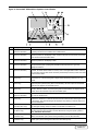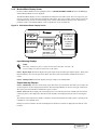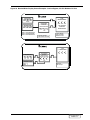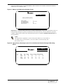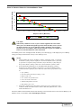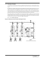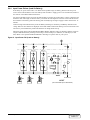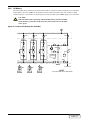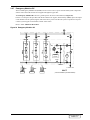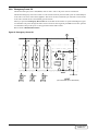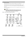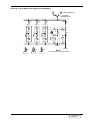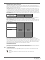
1
DISCONTINUED
PRODUCT
POWER PROTECTION
Series 600T™ UPS
Multi-Module Three Phase
65 kVA to 750 kVA; 60 Hz
Operation & Maintenance
Manual
DISCONTINUED
PRODUCT
TABLE OF CONTENTS
1.0
INTRODUCTION
1.1
System Description . . . . . . . . . . . . . . . . . . . . . . . . . . . . . . . . . . . . . . . . . . . . . . . . . . . . . . . . . . . . . . . . .3
1.3
Safety Precautions . . . . . . . . . . . . . . . . . . . . . . . . . . . . . . . . . . . . . . . . . . . . . . . . . . . . . . . . . . . . . . . . . .8
1.2
1.4
Reliability . . . . . . . . . . . . . . . . . . . . . . . . . . . . . . . . . . . . . . . . . . . . . . . . . . . . . . . . . . . . . . . . . . . . . . . .7
Modes of Operation . . . . . . . . . . . . . . . . . . . . . . . . . . . . . . . . . . . . . . . . . . . . . . . . . . . . . . . . . . . . . . . . .9
1.4.1
1.4.2
1.4.3
1.4.4
1.4.5
1.4.6
1.4.7
1.4.8
Normal (Load on UPS) . . . . . . . . . . . . . . . . . . . . . . . . . . . . . . . . . . . . . . . . . . . . . . . . . . . . . . . . . . . . . . .9
Input Power Failure . . . . . . . . . . . . . . . . . . . . . . . . . . . . . . . . . . . . . . . . . . . . . . . . . . . . . . . . . . . . . . . . . .9
Recharge . . . . . . . . . . . . . . . . . . . . . . . . . . . . . . . . . . . . . . . . . . . . . . . . . . . . . . . . . . . . . . . . . . . . . . . . . .9
Overload . . . . . . . . . . . . . . . . . . . . . . . . . . . . . . . . . . . . . . . . . . . . . . . . . . . . . . . . . . . . . . . . . . . . . . . . . .9
Redundant . . . . . . . . . . . . . . . . . . . . . . . . . . . . . . . . . . . . . . . . . . . . . . . . . . . . . . . . . . . . . . . . . . . . . . . . .9
Bypass (Internal) . . . . . . . . . . . . . . . . . . . . . . . . . . . . . . . . . . . . . . . . . . . . . . . . . . . . . . . . . . . . . . . . . . . .9
Maintenance Bypass . . . . . . . . . . . . . . . . . . . . . . . . . . . . . . . . . . . . . . . . . . . . . . . . . . . . . . . . . . . . . . . . .9
Off-Battery . . . . . . . . . . . . . . . . . . . . . . . . . . . . . . . . . . . . . . . . . . . . . . . . . . . . . . . . . . . . . . . . . . . . . . . .9
1.5
Operator Controls . . . . . . . . . . . . . . . . . . . . . . . . . . . . . . . . . . . . . . . . . . . . . . . . . . . . . . . . . . . . . . . . .10
2.0
THEORY OF OPERATION
1.6
2.1
2.2
3.0
Options. . . . . . . . . . . . . . . . . . . . . . . . . . . . . . . . . . . . . . . . . . . . . . . . . . . . . . . . . . . . . . . . . . . . . . . . . .12
General Component Descriptions . . . . . . . . . . . . . . . . . . . . . . . . . . . . . . . . . . . . . . . . . . . . . . . . . . . . .13
Detailed Component Descriptions. . . . . . . . . . . . . . . . . . . . . . . . . . . . . . . . . . . . . . . . . . . . . . . . . . . . .15
2.2.1
2.2.2
2.2.3
2.2.4
2.2.5
2.2.6
Controls . . . . . . . . . . . . . . . . . . . . . . . . . . . . . . . . . . . . . . . . . . . . . . . . . . . . . . . . . . . . . . . . . . . . . . . . . .15
Rectifier/Charger . . . . . . . . . . . . . . . . . . . . . . . . . . . . . . . . . . . . . . . . . . . . . . . . . . . . . . . . . . . . . . . . . . .16
Battery Charging Circuit . . . . . . . . . . . . . . . . . . . . . . . . . . . . . . . . . . . . . . . . . . . . . . . . . . . . . . . . . . . . .17
Inverter . . . . . . . . . . . . . . . . . . . . . . . . . . . . . . . . . . . . . . . . . . . . . . . . . . . . . . . . . . . . . . . . . . . . . . . . . .18
Static Bypass . . . . . . . . . . . . . . . . . . . . . . . . . . . . . . . . . . . . . . . . . . . . . . . . . . . . . . . . . . . . . . . . . . . . . .19
Redundant Mode . . . . . . . . . . . . . . . . . . . . . . . . . . . . . . . . . . . . . . . . . . . . . . . . . . . . . . . . . . . . . . . . . . .22
OPERATION
3.1
Display Screen and Operator Controls . . . . . . . . . . . . . . . . . . . . . . . . . . . . . . . . . . . . . . . . . . . . . . . . .23
3.2
Modes of Operation . . . . . . . . . . . . . . . . . . . . . . . . . . . . . . . . . . . . . . . . . . . . . . . . . . . . . . . . . . . . . . . .78
3.1.1
3.1.2
3.1.3
3.1.4
3.1.5
3.1.6
3.1.7
3.1.8
3.1.9
3.1.10
3.1.11
3.1.12
3.1.13
3.1.14
Master Menu Screen . . . . . . . . . . . . . . . . . . . . . . . . . . . . . . . . . . . . . . . . . . . . . . . . . . . . . . . . . . . . . . . .29
Monitor/Mimic Display Screen. . . . . . . . . . . . . . . . . . . . . . . . . . . . . . . . . . . . . . . . . . . . . . . . . . . . . . . .31
Walk-In Display Screen. . . . . . . . . . . . . . . . . . . . . . . . . . . . . . . . . . . . . . . . . . . . . . . . . . . . . . . . . . . . . .40
Status Reports Screens . . . . . . . . . . . . . . . . . . . . . . . . . . . . . . . . . . . . . . . . . . . . . . . . . . . . . . . . . . . . . .41
System Configuration Screens . . . . . . . . . . . . . . . . . . . . . . . . . . . . . . . . . . . . . . . . . . . . . . . . . . . . . . . .48
Alarm Limit Settings Screen . . . . . . . . . . . . . . . . . . . . . . . . . . . . . . . . . . . . . . . . . . . . . . . . . . . . . . . . . .55
Load Transfer Procedures Screen . . . . . . . . . . . . . . . . . . . . . . . . . . . . . . . . . . . . . . . . . . . . . . . . . . . . . .57
Start-Up Procedures Screen. . . . . . . . . . . . . . . . . . . . . . . . . . . . . . . . . . . . . . . . . . . . . . . . . . . . . . . . . . .58
Shutdown Procedures Screen . . . . . . . . . . . . . . . . . . . . . . . . . . . . . . . . . . . . . . . . . . . . . . . . . . . . . . . . .60
Battery Time Screen (Module Only). . . . . . . . . . . . . . . . . . . . . . . . . . . . . . . . . . . . . . . . . . . . . . . . . . . .62
Meter Calibration Screen . . . . . . . . . . . . . . . . . . . . . . . . . . . . . . . . . . . . . . . . . . . . . . . . . . . . . . . . . . . .65
Battery Equalize Screen . . . . . . . . . . . . . . . . . . . . . . . . . . . . . . . . . . . . . . . . . . . . . . . . . . . . . . . . . . . . .66
Alarm and Status Messages. . . . . . . . . . . . . . . . . . . . . . . . . . . . . . . . . . . . . . . . . . . . . . . . . . . . . . . . . . .67
Communication Interfaces . . . . . . . . . . . . . . . . . . . . . . . . . . . . . . . . . . . . . . . . . . . . . . . . . . . . . . . . . . .75
3.2.1
3.2.2
Load On Bypass . . . . . . . . . . . . . . . . . . . . . . . . . . . . . . . . . . . . . . . . . . . . . . . . . . . . . . . . . . . . . . . . . . .78
OK To Transfer . . . . . . . . . . . . . . . . . . . . . . . . . . . . . . . . . . . . . . . . . . . . . . . . . . . . . . . . . . . . . . . . . . . .79
DISCONTINUED
PRODUCT
i
3.2.3
3.2.4
3.2.5
3.2.6
3.2.7
3.2.8
3.2.9
3.2.10
Momentary Overloads . . . . . . . . . . . . . . . . . . . . . . . . . . . . . . . . . . . . . . . . . . . . . . . . . . . . . . . . . . . . . . 81
Input Power Failure (Load On Battery) . . . . . . . . . . . . . . . . . . . . . . . . . . . . . . . . . . . . . . . . . . . . . . . . . 82
One Module Off-Line. . . . . . . . . . . . . . . . . . . . . . . . . . . . . . . . . . . . . . . . . . . . . . . . . . . . . . . . . . . . . . . 83
Off Battery . . . . . . . . . . . . . . . . . . . . . . . . . . . . . . . . . . . . . . . . . . . . . . . . . . . . . . . . . . . . . . . . . . . . . . . 84
Emergency Modules Off . . . . . . . . . . . . . . . . . . . . . . . . . . . . . . . . . . . . . . . . . . . . . . . . . . . . . . . . . . . . 85
Emergency Power Off . . . . . . . . . . . . . . . . . . . . . . . . . . . . . . . . . . . . . . . . . . . . . . . . . . . . . . . . . . . . . . 86
System Shutdown . . . . . . . . . . . . . . . . . . . . . . . . . . . . . . . . . . . . . . . . . . . . . . . . . . . . . . . . . . . . . . . . . . 87
Maintenance Bypass . . . . . . . . . . . . . . . . . . . . . . . . . . . . . . . . . . . . . . . . . . . . . . . . . . . . . . . . . . . . . . . . 88
3.3.1
3.3.2
3.3.3
Start-Up Procedure . . . . . . . . . . . . . . . . . . . . . . . . . . . . . . . . . . . . . . . . . . . . . . . . . . . . . . . . . . . . . . . . . 91
Load Transfer Procedures. . . . . . . . . . . . . . . . . . . . . . . . . . . . . . . . . . . . . . . . . . . . . . . . . . . . . . . . . . . . 97
Shutdown Procedures . . . . . . . . . . . . . . . . . . . . . . . . . . . . . . . . . . . . . . . . . . . . . . . . . . . . . . . . . . . . . . . 99
3.4.1
3.4.2
3.4.3
3.4.4
3.4.5
Overloads (Without Transfer). . . . . . . . . . . . . . . . . . . . . . . . . . . . . . . . . . . . . . . . . . . . . . . . . . . . . . . . 103
Automatic Transfers to Bypass. . . . . . . . . . . . . . . . . . . . . . . . . . . . . . . . . . . . . . . . . . . . . . . . . . . . . . . 104
Automatic Retransfers to UPS . . . . . . . . . . . . . . . . . . . . . . . . . . . . . . . . . . . . . . . . . . . . . . . . . . . . . . . 104
Automatic Module Off-Line. . . . . . . . . . . . . . . . . . . . . . . . . . . . . . . . . . . . . . . . . . . . . . . . . . . . . . . . . 105
Automatic Emergency Modules Off. . . . . . . . . . . . . . . . . . . . . . . . . . . . . . . . . . . . . . . . . . . . . . . . . . . 105
3.3
Manual Procedures. . . . . . . . . . . . . . . . . . . . . . . . . . . . . . . . . . . . . . . . . . . . . . . . . . . . . . . . . . . . . . . . 90
3.4
Automatic Operations . . . . . . . . . . . . . . . . . . . . . . . . . . . . . . . . . . . . . . . . . . . . . . . . . . . . . . . . . . . . 103
4.0
MAINTENANCE
4.1
Safety Precautions . . . . . . . . . . . . . . . . . . . . . . . . . . . . . . . . . . . . . . . . . . . . . . . . . . . . . . . . . . . . . . . 106
4.3
Routine Maintenance . . . . . . . . . . . . . . . . . . . . . . . . . . . . . . . . . . . . . . . . . . . . . . . . . . . . . . . . . . . . . 109
4.2
4.4
Liebert Customer Service and Support . . . . . . . . . . . . . . . . . . . . . . . . . . . . . . . . . . . . . . . . . . . . . . . 108
4.3.1
4.3.2
4.3.3
4.3.4
Record Log . . . . . . . . . . . . . . . . . . . . . . . . . . . . . . . . . . . . . . . . . . . . . . . . . . . . . . . . . . . . . . . . . . . . . .
Air Filters . . . . . . . . . . . . . . . . . . . . . . . . . . . . . . . . . . . . . . . . . . . . . . . . . . . . . . . . . . . . . . . . . . . . . . .
Battery Maintenance . . . . . . . . . . . . . . . . . . . . . . . . . . . . . . . . . . . . . . . . . . . . . . . . . . . . . . . . . . . . . .
Torque Requirements . . . . . . . . . . . . . . . . . . . . . . . . . . . . . . . . . . . . . . . . . . . . . . . . . . . . . . . . . . . . . .
109
109
110
115
Detection of Trouble . . . . . . . . . . . . . . . . . . . . . . . . . . . . . . . . . . . . . . . . . . . . . . . . . . . . . . . . . . . . . 115
4.5
Reporting a Problem . . . . . . . . . . . . . . . . . . . . . . . . . . . . . . . . . . . . . . . . . . . . . . . . . . . . . . . . . . . . . 116
4.7
Recommended Test Equipment . . . . . . . . . . . . . . . . . . . . . . . . . . . . . . . . . . . . . . . . . . . . . . . . . . . . . 116
4.6
5.0
Corrective Actions . . . . . . . . . . . . . . . . . . . . . . . . . . . . . . . . . . . . . . . . . . . . . . . . . . . . . . . . . . . . . . . 116
SPECIFICATIONS AND RATINGS
5.1
Rating . . . . . . . . . . . . . . . . . . . . . . . . . . . . . . . . . . . . . . . . . . . . . . . . . . . . . . . . . . . . . . . . . . . . . . . . . 117
5.3
Adjustments . . . . . . . . . . . . . . . . . . . . . . . . . . . . . . . . . . . . . . . . . . . . . . . . . . . . . . . . . . . . . . . . . . . . 119
5.2
5.4
5.5
ii
Environmental Conditions . . . . . . . . . . . . . . . . . . . . . . . . . . . . . . . . . . . . . . . . . . . . . . . . . . . . . . . . 118
Battery Operation . . . . . . . . . . . . . . . . . . . . . . . . . . . . . . . . . . . . . . . . . . . . . . . . . . . . . . . . . . . . . . . . 119
Electrical Specifications . . . . . . . . . . . . . . . . . . . . . . . . . . . . . . . . . . . . . . . . . . . . . . . . . . . . . . . . . . 120
DISCONTINUED
PRODUCT
Figure 1
Figure 2
Figure 3
Figure 4
Figure 5
Figure 6
Figure 7
Figure 8
Figure 9
Figure 10
Figure 11
Figure 12
Figure 13
Figure 14
Figure 15
Figure 16
Figure 17
Figure 18
Figure 19
Figure 20
Figure 21
Figure 22
Figure 23
Figure 24
Figure 25
Figure 26
Figure 27
Figure 28
Figure 29
Figure 30
Figure 31
Figure 32
Figure 33
Figure 34
Figure 35
Figure 36
Figure 37
Figure 38
Figure 39
Figure 40
Figure 41
Figure 42
Figure 43
Figure 44
Figure 45
Figure 46
Figure 47
Figure 48
Figure 49
FIGURES
Multi-Module UPS, 65-80 kVA (left) and 100-500 kVA (right) . . . . . . . . . . . . . . . . . . . . . . . . . . . . . . . . . . .3
Multi-Module 500-750 kVA UPS . . . . . . . . . . . . . . . . . . . . . . . . . . . . . . . . . . . . . . . . . . . . . . . . . . . . . . . . . .5
System Control Cabinets (SCCs) . . . . . . . . . . . . . . . . . . . . . . . . . . . . . . . . . . . . . . . . . . . . . . . . . . . . . . . . . .6
SCC Controls and Display Screen with Example of the Monitor/Mimic Screen . . . . . . . . . . . . . . . . . . . . .10
Module Controls and Display Screen with Example of the Monitor/Mimic Screen . . . . . . . . . . . . . . . . . . . 11
UPS Module Block Diagram . . . . . . . . . . . . . . . . . . . . . . . . . . . . . . . . . . . . . . . . . . . . . . . . . . . . . . . . . . . . .14
System Control Cabinet (SCC) Block Diagram . . . . . . . . . . . . . . . . . . . . . . . . . . . . . . . . . . . . . . . . . . . . . .19
Operator Controls, 65 to 80 kVA (left) and 100 to 500 kVA (right) . . . . . . . . . . . . . . . . . . . . . . . . . . . . . . .24
System Control Cabinet Operator Controls (SCCB Pictured) . . . . . . . . . . . . . . . . . . . . . . . . . . . . . . . . . . .25
Series 600T UPS and SCC Operator Control Panels . . . . . . . . . . . . . . . . . . . . . . . . . . . . . . . . . . . . . . . . . .26
Switches Behind SCC Control Panel Door . . . . . . . . . . . . . . . . . . . . . . . . . . . . . . . . . . . . . . . . . . . . . . . . . .27
Menu Tree . . . . . . . . . . . . . . . . . . . . . . . . . . . . . . . . . . . . . . . . . . . . . . . . . . . . . . . . . . . . . . . . . . . . . . . . . . .28
Master Menu Screens, SCC (above) and Module (below). . . . . . . . . . . . . . . . . . . . . . . . . . . . . . . . . . . . . . .29
SCC Monitor/Mimic Display Screen . . . . . . . . . . . . . . . . . . . . . . . . . . . . . . . . . . . . . . . . . . . . . . . . . . . . . .31
Module Monitor/Mimic Display Screen . . . . . . . . . . . . . . . . . . . . . . . . . . . . . . . . . . . . . . . . . . . . . . . . . . . .33
Monitor/Mimic Display Screen Examples: Normal Power Flowe. . . . . . . . . . . . . . . . . . . . . . . . . . . . . . . . .35
Monitor/Mimic Display Screen Examples: Utility Fail . . . . . . . . . . . . . . . . . . . . . . . . . . . . . . . . . . . . . . . . .36
Monitor/Mimic Display Screen Examples: Load on Bypass, UPS Modules On and Charging Battery . . . .37
Monitor/Mimic Display Screen Examples: Load on UPS, One UPS Module Off Line . . . . . . . . . . . . . . . .38
Monitor/Mimic Display Screen Examples: Load on Bypass, All UPS Modules Off Line . . . . . . . . . . . . . .39
Walk-In Display Screen During Start-Up . . . . . . . . . . . . . . . . . . . . . . . . . . . . . . . . . . . . . . . . . . . . . . . . . . .40
Status Reports Screen . . . . . . . . . . . . . . . . . . . . . . . . . . . . . . . . . . . . . . . . . . . . . . . . . . . . . . . . . . . . . . . . . .41
Present Status Report Screens . . . . . . . . . . . . . . . . . . . . . . . . . . . . . . . . . . . . . . . . . . . . . . . . . . . . . . . . . . . .42
Event History Report Screen . . . . . . . . . . . . . . . . . . . . . . . . . . . . . . . . . . . . . . . . . . . . . . . . . . . . . . . . . . . . .43
History Status Report Screens . . . . . . . . . . . . . . . . . . . . . . . . . . . . . . . . . . . . . . . . . . . . . . . . . . . . . . . . . . . .44
Battery Cycle Monitor Screen . . . . . . . . . . . . . . . . . . . . . . . . . . . . . . . . . . . . . . . . . . . . . . . . . . . . . . . . . . . .46
Battery Cycle Monitoring Summary Screen . . . . . . . . . . . . . . . . . . . . . . . . . . . . . . . . . . . . . . . . . . . . . . . . .47
Typical Data on Discharge Cycles of 91 to 240 Seconds Duration . . . . . . . . . . . . . . . . . . . . . . . . . . . . . . . .47
SCC System Configuration Screen . . . . . . . . . . . . . . . . . . . . . . . . . . . . . . . . . . . . . . . . . . . . . . . . . . . . . . . .48
Date Screen . . . . . . . . . . . . . . . . . . . . . . . . . . . . . . . . . . . . . . . . . . . . . . . . . . . . . . . . . . . . . . . . . . . . . . . . . .49
Time Screen . . . . . . . . . . . . . . . . . . . . . . . . . . . . . . . . . . . . . . . . . . . . . . . . . . . . . . . . . . . . . . . . . . . . . . . . . .50
Auto Dial Setting Screen . . . . . . . . . . . . . . . . . . . . . . . . . . . . . . . . . . . . . . . . . . . . . . . . . . . . . . . . . . . . . . . .51
Modem Baud Rate . . . . . . . . . . . . . . . . . . . . . . . . . . . . . . . . . . . . . . . . . . . . . . . . . . . . . . . . . . . . . . . . . . . . .52
Maximum Auto-Retransfer Attempts Screen . . . . . . . . . . . . . . . . . . . . . . . . . . . . . . . . . . . . . . . . . . . . . . . .53
Module Alarm Limit Settings Screen . . . . . . . . . . . . . . . . . . . . . . . . . . . . . . . . . . . . . . . . . . . . . . . . . . . . . .55
Load Transfer Procedures Screen . . . . . . . . . . . . . . . . . . . . . . . . . . . . . . . . . . . . . . . . . . . . . . . . . . . . . . . . .57
SCC Start- Up Procedures Screen . . . . . . . . . . . . . . . . . . . . . . . . . . . . . . . . . . . . . . . . . . . . . . . . . . . . . . . . .58
Module Start- Up Procedures Screen . . . . . . . . . . . . . . . . . . . . . . . . . . . . . . . . . . . . . . . . . . . . . . . . . . . . . .59
SCC Shutdown Procedures Screen . . . . . . . . . . . . . . . . . . . . . . . . . . . . . . . . . . . . . . . . . . . . . . . . . . . . . . . .60
Module Shutdown Procedures Screen . . . . . . . . . . . . . . . . . . . . . . . . . . . . . . . . . . . . . . . . . . . . . . . . . . . . . .61
Battery Time Screen Example - 15 Minute Discharge . . . . . . . . . . . . . . . . . . . . . . . . . . . . . . . . . . . . . . . . .62
Battery Time Screen Example - 45 Minute Discharge . . . . . . . . . . . . . . . . . . . . . . . . . . . . . . . . . . . . . . . . .63
Range of Values for Calculated Battery Times . . . . . . . . . . . . . . . . . . . . . . . . . . . . . . . . . . . . . . . . . . . . . . .64
Meter Calibration Screen . . . . . . . . . . . . . . . . . . . . . . . . . . . . . . . . . . . . . . . . . . . . . . . . . . . . . . . . . . . . . . . .65
Battery Equalize Screen . . . . . . . . . . . . . . . . . . . . . . . . . . . . . . . . . . . . . . . . . . . . . . . . . . . . . . . . . . . . . . . .66
SCC Status and Alarm Message Areas . . . . . . . . . . . . . . . . . . . . . . . . . . . . . . . . . . . . . . . . . . . . . . . . . . . . .67
Load on Bypass (UPS Not Available) . . . . . . . . . . . . . . . . . . . . . . . . . . . . . . . . . . . . . . . . . . . . . . . . . . . . . .78
Load on Bypass (UPS Available) . . . . . . . . . . . . . . . . . . . . . . . . . . . . . . . . . . . . . . . . . . . . . . . . . . . . . . . . .79
Load on UPS (Bypass Available) . . . . . . . . . . . . . . . . . . . . . . . . . . . . . . . . . . . . . . . . . . . . . . . . . . . . . . . . .80
DISCONTINUED
PRODUCT
iii
Figure 50
Figure 51
Figure 52
Figure 53
Figure 54
Figure 55
Figure 56
Figure 57
Figure 58
Figure 59
Figure 60
Figure 61
Figure 62
Figure 63
Figure 64
Momentary Overload (Pulsed Static Bypass Switch) . . . . . . . . . . . . . . . . . . . . . . . . . . . . . . . . . . . . . . . . . . 81
Input Power Fail (Load on Battery) . . . . . . . . . . . . . . . . . . . . . . . . . . . . . . . . . . . . . . . . . . . . . . . . . . . . . . . 82
One Module Off-Line (Load on UPS) . . . . . . . . . . . . . . . . . . . . . . . . . . . . . . . . . . . . . . . . . . . . . . . . . . . . . 83
Load on UPS (Battery Not Available) . . . . . . . . . . . . . . . . . . . . . . . . . . . . . . . . . . . . . . . . . . . . . . . . . . . . . 84
Emergency Modules Off . . . . . . . . . . . . . . . . . . . . . . . . . . . . . . . . . . . . . . . . . . . . . . . . . . . . . . . . . . . . . . . . 85
Emergency Power Off . . . . . . . . . . . . . . . . . . . . . . . . . . . . . . . . . . . . . . . . . . . . . . . . . . . . . . . . . . . . . . . . . 86
System Shutdown . . . . . . . . . . . . . . . . . . . . . . . . . . . . . . . . . . . . . . . . . . . . . . . . . . . . . . . . . . . . . . . . . . . . . 87
Load on Maintenance Bypass (Two Breakers) . . . . . . . . . . . . . . . . . . . . . . . . . . . . . . . . . . . . . . . . . . . . . . . 88
Load on Maintenance Bypass (Three Breakers) . . . . . . . . . . . . . . . . . . . . . . . . . . . . . . . . . . . . . . . . . . . . . . 89
SCC Start-Up Procedures Screen . . . . . . . . . . . . . . . . . . . . . . . . . . . . . . . . . . . . . . . . . . . . . . . . . . . . . . . . . 93
Module Start-Up Procedures Screen . . . . . . . . . . . . . . . . . . . . . . . . . . . . . . . . . . . . . . . . . . . . . . . . . . . . . . 95
Load Transfer Procedures Screen . . . . . . . . . . . . . . . . . . . . . . . . . . . . . . . . . . . . . . . . . . . . . . . . . . . . . . . . . 97
SCC Shutdown Procedures Screen . . . . . . . . . . . . . . . . . . . . . . . . . . . . . . . . . . . . . . . . . . . . . . . . . . . . . . . . 99
Module Shutdown Procedures Screen . . . . . . . . . . . . . . . . . . . . . . . . . . . . . . . . . . . . . . . . . . . . . . . . . . . . 101
Current-Versus-Time Curve of Module Overload Capacity . . . . . . . . . . . . . . . . . . . . . . . . . . . . . . . . . . . . 103
TABLES
Table 1
Table 2
Table 3
Table 4
Table 5
iv
Alarm Messages - Meaning and Corrective Action . . . . . . . . . . . . . . . . . . . . . . . . . . . . . . . . . . . . . . . . . . . 70
Alarm Messages - Summary . . . . . . . . . . . . . . . . . . . . . . . . . . . . . . . . . . . . . . . . . . . . . . . . . . . . . . . . . . . . . 74
Series 600T Terminal Commands . . . . . . . . . . . . . . . . . . . . . . . . . . . . . . . . . . . . . . . . . . . . . . . . . . . . . . . . . 77
Torque Specifications (Unless Otherwise Labeled) . . . . . . . . . . . . . . . . . . . . . . . . . . . . . . . . . . . . . . . . . . 115
Recommended Test Equipment and Tools. . . . . . . . . . . . . . . . . . . . . . . . . . . . . . . . . . . . . . . . . . . . . . . . . . 116
DISCONTINUED
PRODUCT
IMPORTANT SAFETY INSTRUCTIONS
Save These Instructions.
This manual contains important instructions that should be followed during installation and maintenance of your
Series 600T UPS and batteries.
WARNING
EXERCISE EXTREME CARE WHEN HANDLING UPS CABINETS TO
AVOID EQUIPMENT DAMAGE OR INJURY TO PERSONNEL. REFER TO
SEPARATE INSTALLATION MANUAL FOR EQUIPMENT HANDLING
INFORMATION AND INSTALLATION PROCEDURES.
FOLLOW ALL BATTERY SAFETY PRECAUTIONS IN 4.0 MAINTENANCE WHEN INSTALLING, CHARGING, OR SERVICING
BATTERIES. IN ADDITION TO THE HAZARD OF ELECTRIC SHOCK,
GAS PRODUCED BY BATTERIES CAN BE EXPLOSIVE AND SULFURIC
ACID CAN CAUSE SEVERE BURNS.
IN CASE OF FIRE INVOLVING ELECTRICAL EQUIPMENT, USE ONLY
CARBON DIOXIDE FIRE EXTINGUISHERS, OR OTHERS APPROVED
FOR USE IN ELECTRICAL FIRE FIGHTING.
EXTREME CAUTION IS REQUIRED WHEN PERFORMING
MAINTENANCE.
BE CONSTANTLY AWARE THAT THE UPS SYSTEM CONTAINS HIGH
DC AS WELL AS AC VOLTAGES. WITH INPUT POWER OFF AND THE
BATTERY DISCONNECTED, HIGH VOLTAGE AT FILTER CAPACITORS
AND POWER CIRCUITS SHOULD BE DISCHARGED WITHIN 30
SECONDS. HOWEVER, IF A POWER CIRCUIT FAILURE HAS
OCCURRED, YOU SHOULD ASSUME THAT HIGH VOLTAGE MAY
STILL EXIST AFTER SHUTDOWN. CHECK WITH A VOLTMETER
BEFORE MAKING CONTACT.
AC VOLTAGE WILL REMAIN ON THE SYSTEM BYPASS (SBB) AND UPS
OUTPUT CIRCUIT BREAKERS, AND THE STATIC BYPASS SWITCH,
UNLESS ASSOCIATED EXTERNAL CIRCUIT BREAKERS ARE OPENED.
CHECK FOR VOLTAGE WITH BOTH AC AND DC VOLTMETERS PRIOR
TO MAKING CONTACT.
WHEN THE UPS SYSTEM IS UNDER POWER, BOTH THE OPERATOR
AND ANY TEST EQUIPMENT MUST BE ISOLATED FROM DIRECT
CONTACT WITH EARTH GROUND AND THE UPS CHASSIS FRAME BY
USING RUBBER MATS.
SOME COMPONENTS WITHIN THE CABINETS ARE NOT CONNECTED
TO CHASSIS GROUND. ANY CONTACT BETWEEN FLOATING
CIRCUITS AND THE CHASSIS IS A LETHAL SHOCK HAZARD.
EXERCISE CAUTION THAT THE TEST INSTRUMENT EXTERIOR DOES
NOT MAKE CONTACT EITHER PHYSICALLY OR ELECTRICALLY
WITH EARTH GROUND.
DISCONTINUED
PRODUCT
1
OVERVIEW
OF
THIS MANUAL
The manual is organized so that information can be found quickly. Each major topic is separated by sections, and
the Table of Contents contains major headings within each section. The names of the sections and their contents
are described below.
1.0 - Introduction is a summary of the Series 600T UPS System. It describes some of the unique features and
benefits of the Series 600T, as well as the design principles and standards that Liebert follows in the manufacture
of each system. Descriptions of the Series 600T system and an overview of its functions are also included.
2.0 - Theory of Operation is an explanation of the major circuit groups of the Series 600T UPS. This section is
for individuals who want to know both the basics and the specifics of each major component. The text explains
how the UPS handles electrical disturbances and interruptions.
3.0 - Operation is written for facility personnel responsible for the operation of the system. It details the procedures required to start-up each module and the system, to transfer the load between the available sources, and to
shut down each module and the system. Both manual and automatic operations are described. Operator controls
and displays, including the solid state liquid crystal display (LCD) screen, are illustrated and explained for the
UPS Module and for the System Control Cabinet (SCC).
4.0 - Maintenance lists routine maintenance checks and helps the user pinpoint and quickly resolve problems if
they arise.
5.0 - Specifications and Ratings gives detailed specifications about the Series 600T UPS System. This technical
information is of use to installing contractors, engineers, and service personnel.
If you require assistance for any reason, call the toll-free Liebert Global Services number: 1-800-543-2378. For
LGS to assist you expediently, please have the following information available:
Part Numbers:
Serial Numbers:
kVA Rating:
Date Purchased:
Date Installed:
Location:
Input Voltage:
Output Voltage:
Battery Reserve Time:
2
______________________________________________________________
______________________________________________________________
______________________________________________________________
______________________________________________________________
______________________________________________________________
______________________________________________________________
______________________________________________________________
______________________________________________________________
______________________________________________________________
DISCONTINUED
PRODUCT
1.0
INTRODUCTION
1.1
System Description
The role of the parallel-redundant multi-module UPS system is to supply uninterruptible, clean power to the critical load. It maintains a full-voltage, low-distortion output, even if the utility source power sags or becomes distorted.
If there is an outage of the source power, the UPS maintains power to the load until an alternate source of power
is activated, or until the original power source is restored. If input AC power is not restored, the UPS maintains
the load (with the battery plant) long enough that the critical equipment can be shut down in an orderly manner.
The Series 600T UPS module displays the rate of battery discharge and calculates the amount of battery time
remaining based on the actual connected load. The time that the battery will maintain the load depends on the
capacity of the battery backup plant and the size of the load.
The system control logic automatically manages critical bus operation. System logic is resident in Application
Specific Integrated Circuits (ASICs) for precise control and improved reliability.
If the critical load current exceeds the rated load of the Series 600T UPS system, the control logic determines the
magnitude of the overload and reacts appropriately. Overloads are usually the result of inrush current requirements. The UPS system supports loads that are 150% of the rated load for up to 30 seconds and 125% of the
rated load for up to ten minutes. If the system is operating in the non-redundant mode (e.g., a UPS module is off
line), the overload limits are automatically adjusted.
Figure 1
Multi-Module UPS, 65-80 kVA (left) and 100-500 kVA (right)
If the load surpasses the overload capacity of the UPS, the load is automatically transferred to bypass without
interruption. When the load returns to within the UPS rating, it is either automatically or manually returned
Introduction
DISCONTINUED
PRODUCT
3
(retransferred) to the UPS. How and when the load is returned to the UPS depends on several factors: how long
the overload lasted, how many overload conditions occurred before transfer, whether there is an imminent failure
of any part of the UPS, etc. Refer to 3.4 - Automatic Operations.
In the unlikely event of a fault within the UPS, the SCC control logic, which continuously monitors all critical
circuits within the UPS system, transfers the load to bypass without interruption and simultaneously sets off local
and remote alarms. If a fault is detected in an individual UPS module, that module is automatically disconnected
from the critical bus and shut down. A Module Off Line status message will appear at the SCC display. The
module can be manually returned to service when the fault has been corrected.
If the multi-module UPS system is operating in the redundant mode (at least one extra module is available for the
connected critical load), the load will remain on the UPS system if one individual module is disconnected from
the critical bus (off line). If the UPS system is operating in the non-redundant mode, the load will be automatically transferred to bypass if a module goes off line.
The Series 600T UPS display system provides precise monitoring of the UPS, fast alarm response, and quick
troubleshooting. For easy manual operations, menu-driven software provides access to several step-by-step help
screens. All operator functions are performed using menu-prompted displays and a minimum number of operator
controls. The System Control Cabinet includes external communication capability with both automatic dial-out
and dial-in features for early warning and diagnosis of abnormal conditions.
The system software allows the operator, or Liebert Global Services, to enter application specific information.
Overload, overvoltage, battery discharge, and shutdown limits can be set by the operator. In effect, the software
is tailored for each site.
The UPS system protects critical equipment from source power disturbances and outages, load faults, and UPS
malfunctions. This triple protection virtually eliminates computer and computing equipment downtime as a
result of utility source power problems.
4
Introduction
DISCONTINUED
PRODUCT
Figure 2
Multi-Module 500-750 kVA UPS
Introduction
DISCONTINUED
PRODUCT
5
Figure 3
System Control Cabinets (SCCs)
Types of System Control Cabinets (SCCs)
• SCCT -- A stand-alone cabinet containing system control logic for up to six UPS modules, a static bypass
switch, manually operated disconnects for the static bypass switch, and two motor-operated system circuit
breakers.
• SCCB -- Similar to the SCCT, except that external sheet metal matches that of the UPS modules.
• SCCP -- Similar to the SCCB, except narrower and designed for two UPS modules.
• SCCI -- System control logic and static bypass switch are integrated into a switchboard cabinet manufactured by others, which also includes the system circuit breakers.
• SCCC -- An integrated configuration like the SCCI, but with a static switch rated for continuous duty.
6
Introduction
DISCONTINUED
PRODUCT
1.2
Reliability
Reliability is the most important design goal for Uninterruptible Power Systems. Liebert Series 600 UPS systems
have demonstrated reliability by achieving a field-proven critical bus MTBF in excess of one million hours. In
addition, our Quality Assurance program is certified to the requirements of ISO 9001 standards.
Liebert Large UPS systems are ETL listed to the requirements of UL 1778. All equipment and components are
manufactured to applicable UL, NEC, NEMA, ANSI, IEEE, and CSA standards and guidelines.
Designed for Success
The keys to reliability in the design of the UPS system are using conservatively rated components, minimizing
transfers to bypass, making operator controls understandable, and providing easy access for maintenance and
repair. Liebert UPS systems lead the industry in all these areas.
For example, the Series 600T can clear substantial overloads through the solid state static bypass switch without
transferring to the bypass source. By minimizing transfers to bypass, the Series 600T minimizes operation of circuit breakers and enhances system reliability.
As another example, the system control logic has been packaged into Application-Specific Integrated Circuits
(ASICs) to eliminate the failure-prone discrete logic boards used in other brands of UPS products. Furthermore,
these ASICs are isolated from heat-generating components to ensure optimal operating temperatures.
Other Factors to Consider
Reliability depends on more than just UPS module design. Improper installation can cause any system to fail. To
prevent this, Customer Engineers from Liebert Global Services thoroughly inspect the installation of all our systems to ensure they are installed properly and operating within performance specifications.
Once a UPS is properly installed, you—the on-site equipment operator—are the most important factor in preventing critical bus failures or unplanned transfers to bypass. To make your task easier, the Series 600T UPS provides easy-to-follow, prompted instructions on the industry’s largest operator display screen.
If you ever need help, call Liebert Global Services (24 hours a day at 1-800-543-2378). Your attention to proper
installation, operation, and periodic maintenance will ensure that your mission-critical operations receive the
best possible protection from electrical disturbances and outages.
Introduction
DISCONTINUED
PRODUCT
7
1.3
Safety Precautions
Read this manual thoroughly, paying special attention to the sections that apply to you, before working with the
UPS. Also read the battery manufacturer’s manual before working on or near the battery.
Under typical operation and with all UPS doors closed, only normal safety precautions are necessary. The area
around the UPS system and Battery should be kept free from puddles of water, excess moisture, or debris.
Special safety precautions are required for procedures involving handling, installation, and maintenance of the
UPS system or the battery. Observe precautions in the separate Installation Manual before handling or installing
the UPS system. Observe precautions in 4.0 - Maintenance, before as well as during performance of all maintenance procedures. Observe all battery safety precautions in 4.0 - Maintenance before working on or near the
battery.
This equipment contains several circuits that are energized with high voltage. Only test equipment designated for troubleshooting should be used. This is particularly true for oscilloscopes. Always check with an AC
and DC voltmeter to ensure safety before making contact or using tools. Even when the power is turned Off, dangerously high potentials may exist at the capacitor banks. Observe all battery precautions when near the battery
for any reason.
ONLY qualified service personnel should perform maintenance on the UPS system. When performing
maintenance with any part of the equipment under power, service personnel and test equipment should be standing on rubber mats. The service personnel should wear insulating shoes for isolation from direct contact with the
floor (earth ground).
Unless all power is removed from the equipment, one person should never work alone. A second person should
be standing by to assist and summon help in case an accident should occur. This is particularly true when work is
performed on the battery.
Three types of messages are used throughout the manual to stress important text. Carefully read the text below
each Warning, Caution, and Note and use professional skills and prudent care when performing the actions
described by that text.
A Warning signals the presence of a possible serious, life-threatening condition. For example:
WARNING
LETHAL VOLTAGES MAY BE PRESENT WITHIN THIS UNIT EVEN
WHEN IT IS APPARENTLY NOT OPERATING. OBSERVE ALL
CAUTIONS AND WARNINGS IN THIS MANUAL. FAILURE TO DO SO
COULD RESULT IN SERIOUS INJURY OR DEATH. DO NOT WORK ON
OR OPERATE THIS EQUIPMENT UNLESS YOU ARE FULLY QUALIFIED
TO DO SO!! NEVER WORK ALONE.
A Caution indicates a condition that could seriously damage equipment and possibly injure personnel. For
example:
CAUTION
Make sure you understand the proper sequence before operating any circuit
breaker. Operating a Maintenance Bypass circuit breaker out of sequence could
cut off power to the critical load.
A Note emphasizes important text. If the note is not followed, equipment could be damaged or may not operate
properly. For example:
NOTE
If the UPS system has a blown fuse, the cause should be determined before you
replace the fuse. Contact Liebert Global Services.
8
Introduction
DISCONTINUED
PRODUCT
1.4
Modes of Operation
1.4.1
Normal (Load on UPS)
1.4.2
1.4.3
1.4.4
1.4.5
1.4.6
1.4.7
1.4.8
Refer to 2.0 - Theory of Operation and 3.0 - Operation for more details.
The utility AC source provides power to the rectifier/charger in each UPS module. Each rectifier/charger converts the utility AC power to DC and supplies DC power to the UPS module inverter while simultaneously float
charging the battery plant. Each UPS module inverter converts DC to AC and furnishes AC power to the critical
bus. The System Control Cabinet (SCC) is the tie point for the paralleled modules and monitors and controls the
critical bus performance.
Input Power Failure
If the utility source power fails or is outside the acceptable range, the battery plant becomes the primary supplier
of DC power to the inverter.
Recharge
After the utility source power is restored, or an alternate power source becomes available, each rectifier/charger
slowly walks-in to once again power the inverters and recharge the battery plant.
Overload
Overloads in critical systems may be caused by inrush currents during connected equipment start-up or by faults
in the critical load. The Liebert Series 600T UPS system can maintain full output voltage regulation while sustaining the following overloads:
• Up to 150% for 30 seconds
• Up to 125% for 10 minutes
• Up to 104% for an indefinite period of time
Also, for clearing momentary faults above 155% of rated SCC current, the static switch turns on for 40 milliseconds to supply power from the bypass source. Up to 1000% of the rated current can be supplied for less than one
cycle, while up to 500% of rated load can be sustained for the full 40 milliseconds of pulsed-parallel operation.
The critical load remains on the UPS modules for the above conditions. If the UPS system overload capacity is
exceeded, an automatic transfer to bypass is initiated, which closes the system bypass circuit breaker (SBB) and
opens the UPS output circuit breaker.
Whenever you have an overload condition, you should determine the cause of the overload.
Redundant
If the multi-module UPS system includes one more module than the number required to supply the critical load,
the UPS system can operate in the redundant mode. This means that the load will remain on the UPS system if
one of the modules is disconnected because of an overload, an internal fault, or for maintenance. If the additional
module is not included in the system design, or if the additional module is disconnected from the critical bus, the
UPS system operates in the non-redundant mode.
Bypass (Internal)
The SCC control logic initiates an automatic transfer to the bypass source if the overload-current-versus-time
curve is exceeded or if specified UPS system faults occur. You can also manually transfer the load to the bypass
(without interruption) if you must take the UPS module out of service for maintenance.
The SCC internal maintenance bypass will allow most key components and operating modes to be checked without disturbing the critical bus. However, certain key power-carrying components, such as the output and bypass
circuit breakers, will require complete system shutdown or isolation through an external maintenance bypass
cabinet for 100% service.
Maintenance Bypass
The installation of a Maintenance Bypass Cabinet, Panelboard or Switchboard is recommended to allow you to
totally isolate the UPS from all power sources. Use of the Maintenance Bypass is described in 3.0 - Operation.
Off-Battery
The battery plant can be disconnected from the rectifier/charger by using an external Module Battery Disconnect
(MBD circuit breaker). The UPS module continues to function normally, though it does not have power outage
back-up capability until the battery plant is reconnected.
Introduction
DISCONTINUED
PRODUCT
9
1.5
Operator Controls
The Liebert Series 600T UPS System Control Cabinet (SCC) and each individual module are equipped with a
microprocessor-based Operator Display Screen and Control Panel designed for convenient and reliable operation.
The front panel location of the monitoring and control system enables the user to quickly identify the current status of the UPS and to perform most of the manual operations. The operator display screen is driven by an easyto-follow menu-prompted software program that controls and monitors the UPS system.
Figure 4
SCC Controls and Display Screen with Example of the Monitor/Mimic Screen
The operator controls and Monitor/Mimic screen for the System Control Cabinet (SCC) are shown in Figure 4.
The controls and display screen for each UPS module are shown in Figure 5. Each cabinet (SCC or module) has
the displays and controls required to monitor and perform its functions.
Figure 4 shows a three-module system designed for redundant operation. A multi-module UPS system may
include up to six (6) modules for each SCC.
Detailed instructions on how to interpret the displays and use the controls are in 3.0 - Operation.
10
Introduction
DISCONTINUED
PRODUCT
Figure 5
Module Controls and Display Screen with Example of the Monitor/Mimic Screen
Introduction
11
DISCONTINUED
PRODUCT
1.6
Options
A number of standard pre-designed options are available from Liebert for your UPS system. Described below are
the most frequently provided options. Note that the battery items (1-3) are required to complete the UPS system.
The remaining options provide improved system performance or convenience.
1.
Battery
The batteries provide power in the event of a power outage. The Liebert UPS can use a variety of battery
types, provided the battery plant is designed for the UPS DC voltage range and the load requirements of
your application.
2. Battery Racks or Cabinets
The battery racks are specifically designed for stationary service batteries. They are painted with electrolyteresistant paint for corrosion resistance. Battery cabinets are available for 150 through 600 kVA modules.
3. Module Battery Disconnect
The UPS system utilizes a separate Module Battery Disconnect for remotely located batteries. A sensing circuit in the UPS module, set at the battery low voltage limit, trips the Module Battery Disconnect to safeguard the battery from excessive discharge. The Module Battery Disconnect has an undervoltage release
mechanism designed to ensure that during any shutdown or failure mode all battery potential is removed
from the UPS system
4. Input Distortion Filter
This filter reduces rectifier input current reflected harmonic distortion to less than 7% THD, and less than
4% THD for modules with the optional 12-pulse rectifier. The filter is factory installed within the UPS. This
filter also improves the input power factor to better than 0.92 lagging.
5. 12-Pulse Rectifier
Certain models may be ordered with the optional 12-pulse rectifier section. This provides input isolation and
reduces reflected input current THD to less than 9%, or less than 4% with optional input filter.
6. Isolation Transformers
An optional rectifier input isolation transformer is available in a matching transformer cabinet. A bypass isolation transformer is also available.
7. Three Breaker Maintenance Bypass
This switchboard provides make-before-break maintenance bypass. It includes: UPS Bypass Input Breaker
(BIB), Maintenance Bypass Breaker (MBB), and Maintenance Isolation Breaker (MIB).
8. Two Breaker Maintenance Bypass
This switchboard provides make-before-break maintenance bypass. It includes: Maintenance Bypass
Breaker (MBB) and Maintenance Isolation Breaker (MIB).
9. Load Bus Synchronization (LBS)
The Load Bus Sync (LBS) option keeps two independent UPS systems (and therefore their critical load
buses) in sync, even when the modules are operating on batteries or asynchronous AC sources. This means
that critical loads connected to both load buses through a Static Bus Transfer Switch can be switched seamlessly between the two.
10. SiteScan Central Monitoring System
Liebert manufactures a central monitoring system that automatically displays key UPS measurements and
alarms, as well as data from a variety of sensors. This monitoring system signals alarms so corrective action
can be taken. Events and data can be printed in hard copy. Data can be logged for analysis.
11. Remote Monitor Panel
The UPS system may also be provided with an optional Remote Monitor Panel. This Panel provides eight
LED indicators and may be placed at a convenient location near the critical load. A functional description of
the Remote Monitor Panel is provided in 3.0 - Operation of this manual.
12. Customer Alarm Interface
This optional interface board allows the input and display of 8 alarms from customer-supplied contacts, each
with a customer-selected name of up to 16 characters. The following attributes can be user programmed for
each alarm: latching, summary, freeze history, sound horn, auto-dial, and time delay (0 to 999.9 seconds).
12
Introduction
DISCONTINUED
PRODUCT
2.0
THEORY OF OPERATION
2.1
General Component Descriptions
The UPS system includes all of the equipment necessary to continuously provide computer-grade AC power to a
critical load, even when there is an interruption of the utility line power. It consists of a System Control Cabinet
(SCC), UPS modules, and a back-up battery plant. Refer to Figure 6 and Figure 7. Except where otherwise
noted, the configuration is presumed to be parallel-redundant (with at least one more UPS module than required
to support the rated load).
System Control Cabinet
The System Control Cabinet (SCC) includes system controls, static bypass switch, load transfer control, protective devices, and other accessories. The system controls simultaneously monitor two or more parallel UPS modules sharing a critical load for increased capacity and/or redundancy. The two (2) motor-operated system circuit
breakers (system bypass breaker—SBB and UPS output breaker) may be contained within the SCC, depending
on the configuration designed for your installation.
System Controls: The system control logic automatically manages critical bus operation and monitors performance of the UPS modules. Microprocessor technology and dedicated firmware provide advanced logic control
and a comprehensive display of information. The system control logic synchronizes the output of the UPS system to the bypass source. The SCC includes ports for communicating with external devices. Liebert Multi-Module Units do not require an SCC for load sharing. Automatic, parallel module load sharing is a function built into
the modules themselves; however interconnection through the SCC enables the modules to share data for more
precise control. Modules do not require master clocks or controls in order to load share or free-run at 60.0 Hz.
Static Bypass Switch: The static (solid-state) bypass switch immediately transfers the load from the inverter to
the bypass AC power source in the event of a severe overload on the system or a failure within the UPS. This
transfer takes place without any interruption of the power supplied to the load. The system includes redundant
circuits to detect and isolate shorted SCRs in the static switch.
Fuses are installed in series with the static bypass circuit to ensure reliable overload protection in the unlikely
event of a catastrophic output condition (e.g., a dropped wrench) electrically close to the output of your UPS system. The static switch SCRs themselves are rated to easily handle the fuse-blowing current.
Bypass Circuit: The bypass circuit consists of electrically operated circuit breakers and associated synchronizing and control circuitry to transfer the load to/from the bypass source.
Theory of Operation
DISCONTINUED 13
PRODUCT
Figure 6
UPS Module Block Diagram
MULTI-MODULE UPS SYSTEM
Control
Wiring
To SCC
CONTROL POWER
Controls
Utility
Input
Power
Input
CB
Rectifier/
Charger
Inverter
MBD
Output
CB
Output
Power
To SCC
Battery
CB - Circuit Breaker
MBD - Module Battery Disconnect
SCC - System Control Cabinet
UPS Module
The UPS module consists of module controls, a rectifier/charger, an inverter, protective devices, and other accessories.
Module Controls: The module control logic monitors performance of the UPS module. The UPS module status
is displayed locally and is also sent to the System Control Cabinet.
Rectifier/Charger: The rectifier/charger converts utility power from AC to DC to charge the battery and provide the DC input to the inverter. Its design limits reflected harmonic current distortion to source power and provides low-ripple DC power for charging batteries. Multiple rectifier/chargers can share a common battery plant,
if that configuration is preferred for your application.
Inverter: The inverter converts DC power into the precise AC power required to supply a sensitive critical load.
The inverter converts DC power into a pulse-width-modulated (PWM)/six-step waveform that is easily filtered
into a clean sine wave output. The PWM/stepwave also minimizes the harmonic voltage distortion caused by
typical switching power supplies and other non-linear load components used in computers and related electronics.
Battery Plant
The battery is used as the alternate source of power to supply DC power to the inverter if the AC supply voltage
is outside the acceptable range. The battery supplies power to the inverter until the utility power is restored or
until an alternate power source is available. If AC source power is not restored or an alternate power source is not
available, the battery can be sized to provide power long enough for an orderly shutdown of the load.
14
Theory of Operation
DISCONTINUED
PRODUCT
2.2
Detailed Component Descriptions
2.2.1
Controls
Hardware
The Series 600T UPS Operator Interface Display System is designed to provide all of the information that is
required for the operation of each UPS cabinet (the System Control Cabinet and each module). The following is
a list of the hardware features:
1.
2.
3.
4.
The control logic performs automatic operations with minimal operator interface. The limited number of
manual controls are easy-to-use.
Each Series 600T UPS cabinet is equipped with an easy-to-read 640 x 200 pixel liquid crystal display (LCD)
screen. It presents information in a way that is easy to understand at an eye-level front panel location.
The display is controlled by a dedicated microprocessor with a non-volatile (EPROM) program and a
battery-backed event memory.
The Series 600T System Control Cabinet (SCC) has communication ports (terminal board connections) for:
a. Transmission of present status information to remote terminals via resident auto-dial communications
program and an external modem. This port also responds to inquiries of the UPS system status and
history from the remote terminal.
b. Reporting UPS system status and history information in response to inquiries from a local terminal (no
modem required).
c. Reporting to a local monitor the information requested from the local terminal.
d. Reporting information to a Liebert SiteScan central monitoring system.
e. Relaying selected alarm messages to a Liebert Remote Monitor Panel and to a separate terminal board
for customer use.
f. Relaying performance and status information to your network monitoring system via SNMP interface.
NOTE
All external communication devices are optional equipment.
Firmware
The Operator Interface Display System software enables the operator to monitor the UPS system status, to control the power flow through the UPS, to monitor all of the meter readings, to execute the start-up, shutdown, and
the load transfer procedures, to access the event history files, and to make adjustments to the programmable
parameters. The following is a list of the firmware features:
1.
2.
3.
4.
5.
The menu-driven software prompts the operator for input.
Step-by-step instructions assist the operator during start-up, shutdown, and load transfer procedures. This
helps to eliminate operator errors.
Graphics-based mimic diagrams illustrate circuit breaker status and the power flow through the UPS system.
The Present Status screen reports information about the system’s present status. The History Status screen
chronicles the events leading up to and immediately after a fault. The Event History screen lists all of the
alarm messages that have been logged over a period of time.
The Battery Cycle Monitor records information on up to 132 battery discharge events. Information includes
date, time, length of discharge, highest current demand, lowest battery voltage, and cumulative battery amp
hours discharged.
Refer to 3.0 - Operation for a description of the controls and indicators located on the Operator Control Panel.
2.2.2
Rectifier/Charger
The UPS module rectifier/charger consists of an input circuit breaker, optional input isolation transformer, AC
current limiting circuit, battery equalize charge circuit, DC filter, battery charge current limiting circuit, and
bridge rectifiers.
Operation
The rectifier/charger converts the AC input power to DC power. This conversion is accomplished by 3-phase
bridge rectifiers using SCRs. All phases are individually fused. Reflected input current THD is less than 7% at
Theory of Operation
DISCONTINUED 15
PRODUCT
full load with optional input filter. For modules 500 kVA and larger, the optional 12-pulse rectifier reduces
reflected THD to less than 4% with optional filter, or 9% without.
The filtered output of the rectifier/charger provides regulated DC power to drive the inverter and charge the battery.
Input Circuit Breaker
The input circuit breaker (CB1) is sized to allow enough current to recharge the battery and supply a full rated
load at the same time. The circuit breaker contains a thermal magnetic trip mechanism and an undervoltage
release that interrupts power, preventing damage to the system, if there is an internal AC over-current condition
or a short circuit. The circuit breaker also opens during certain alarmed faults. This circuit breaker must be closed
manually.
Isolation Transformer
The optional input isolation transformer has a dry type core, and copper windings with class H insulation. The
transformer on modules with standard 6-pulse rectifier has wye primary and delta secondary windings. For models with the optional 12-pulse rectifier, the transformer has a delta primary, with delta and wye secondary windings. The isolation transformer provides the initial step of critical bus isolation. This reduces the AC shock
hazard at the battery and at other DC components, and prevents a DC fault from disrupting upstream AC circuitry.
The transformer has a nominal tap and one tap 6% below the rated nominal input voltage (normally used for 460
VAC input).
Input Current Limit
AC input current-sensing transformers (CTs) are used to measure current levels. Control circuitry connected to
the CTs restricts the AC current to less than 125% of the full input current rating by reducing the battery charging
voltage. This current limit is adjustable from 100 to 125% and is factory set at 115%. A second (optional) level
of input current limit can be initiated by an external contact closure (field supplied for use with back-up generator), and is adjustable from 85 to 100% (factory set at 100%).
During a start-up procedure, the current slowly ramps up (walks-in) from 20% of the rated input current to 100%
over a 15 to 21 second period. The maximum rate of change of the AC input current is 15% per second. The
input current walk-in reduces the start-up surge distortion effects on all other equipment connected to the same
source and prolongs the service life of internal components.
Input Current Inrush
The maximum sub-cycle of inrush current due to the optional input isolation transformer is less than 500-800%
of the rated input current for the first 1/2 cycle. Without the optional transformer, inrush current is typically less
than 2-3 times normal.
Input Power Factor
The rated input power factor is no less than 0.85 lagging at the nominal input voltage and the full rated UPS load.
The optional input filter will improve the power factor to better than 0.92 lagging at full load. Refer to published
specifications for your UPS model.
2.2.3
Battery Charging Circuit
The UPS module charging circuit is capable of recharging the battery plant to 95% of full capacity within 10
times the discharge time. Recharging the last 5% takes longer because of characteristics inherent in the battery.
DC ripple voltage is limited to less than 0.5% RMS to preserve battery life during long-term float charging while
the UPS system is operating on utility source power.
Multiple UPS module rectifier/chargers can share a common battery plant, if that configuration is preferred for
your application.
Operation After Discharge
When commercial power is interrupted, the battery continues to supply DC power to the inverter without interruption to the critical load. If the AC source power is restored before the battery has fully discharged, the rectifier
automatically restarts and resumes carrying the inverter and battery recharge load requirements.
16
Theory of Operation
DISCONTINUED
PRODUCT
Operation After End-of-Discharge
The battery time screen displayed on the control panel enables you to estimate when battery shutdown will occur.
You will have enough time to energize an alternate AC power source or to initiate an orderly shutdown of the
critical load. If the battery plant discharges to the shutdown point during an outage, the UPS automatically disconnects the load, the AC input, and the battery. After AC input power is restored, the rectifier can be manually
restarted by the user.
Battery Disconnect
The external module battery disconnect (MBD) circuit breaker is used to isolate the UPS module from the battery during maintenance and to automatically disconnect the battery from the inverter at the end of battery discharge. The MBD circuit breaker can be opened or tripped automatically, from the control panel, or manually. It
must be closed manually.
Battery Charge Current Limiting
The battery recharge current, after a battery discharge, is limited to between 1 and 25% (adjustable) of the full
load discharge current. An additional (optional) charge-limiting circuit can be activated by external dry contact
closure (field supplied) for use when operating on a back-up generator. These two levels of control regulate the
amount of current that flows from the power source to the battery while the battery is recharging.
The battery charge current limit is factory set at 10% for normal operation and at 1% for alternate power source
recharge operation.
Battery Equalize Charge Circuit
The battery equalize charge feature can be manually initiated or it can be programmed to operate automatically.
Either can be selected from the battery equalize screen displayed on the control panel.
The battery equalizing charge circuit increases the rectifier/charger output voltage to charge the battery any time
there is a power outage of 30 seconds or longer. The equalizing voltage is slightly higher than the float voltage.
This decreases the time required to recharge the battery.
NOTE
Do not use equalize charging with valve-regulated lead-acid batteries
Consult the battery manufacturer's manual for specific information about equalize
charging.
Theory of Operation
DISCONTINUED 17
PRODUCT
2.2.4
Inverter
The inverter is a solid state device that converts the DC output of the rectifier/charger or the battery to AC power.
Operation
The inverter converts DC power—from either the battery or the rectifier/charger—into three pulse-width-modulated/six-step waveforms. These waveforms are filtered into low-distortion sine wave power. The inverter is controlled by an Application-Specific Integrated Circuit (ASIC). This integrated circuit controls the precise
synchronization, amplitude, and frequency of the output voltage.
In addition to the inverter efficiently supplying a regulated AC output from a DC source, the output isolation
transformer acts as a second stage of isolation between the critical load bus and the commercial source power.
The inverter is configured to handle most critical load inrush surges. It maintains output voltage Total Harmonic
Distortion (THD) within specifications even when handling non-linear computer loads. Refer to non-linear load
characteristics.
Output Regulation and Overload Performance
The inverter is capable of sustaining full output voltage ±2% of the nominal voltage) for up to 150% overload at
the output for as long as 30 seconds without reducing the output voltage. It can also handle at least 125% of the
rated current for up to 10 minutes and 104% of the rated current continuously. The System Control Cabinet
(SCC) will transfer the critical load to the bypass source if the overload exceeds the system capacity or the capacity of the modules on-line. The multi-module overload capacity (in terms of percent of rated full load current of
modules on-line) is 140% for 20 seconds, 108% for 10 minutes, and 104% continuously.
Note that in normal operation the SCC will transfer the load to bypass before a UPS module exceeds its overload
capacity. If a module overload condition is sustained (beyond inverter capacity) the UPS module is automatically
taken off-line (disconnected from the critical bus) and is shut down. If the UPS system is operating in the redundant mode, the load may remain on the UPS system. Refer to 3.4 - Automatic Operations.
Non-Linear Load Characteristics
Computers and computer equipment with switching power supplies generate non-linear currents rich in fifth and
seventh harmonics.
The inverter pulse-width-modulated/six-step waveform, coupled with the output filter, provides a natural path
for reducing the fifth and seventh harmonic currents produced by the load. The inverter/filter limits the output
voltage THD to less than 5% with up to 100% typical electronic data processing (EDP) loads. EDP equipment
characteristically includes both non-linear and linear load components.
Unbalanced Load Characteristics
Unbalanced loads are actively regulated. The phase-to-phase voltage balance is maintained to within 2%, even
with a 50% load imbalance.
The three-phase, root mean square (RMS—approximately 70% of the peak) average voltage is also regulated
through a separate control circuit (phase-to-phase sensing).
18
Theory of Operation
DISCONTINUED
PRODUCT
2.2.5
Static Bypass
A static bypass is an integral part of the UPS System Control Cabinet (SCC). Refer to Figure 7. The static
bypass consists of solid-state switching devices working in conjunction with the motor-operated System Bypass
Breaker (SBB). An automatic transfer control circuit senses the status of the operator controls, UPS logic signals
and alarm messages, and critical bus operating conditions. If the UPS modules can no longer supply the critical
load, the static bypass switch (in conjunction with the SBB and UPS Output Breaker) automatically transfers the
critical load to the bypass source without interruption.
Figure 7
System Control Cabinet (SCC) Block Diagram
Gate
Driver
Static
Bypass
Switch
Static Switch
Disconnects
Static Bypass Breaker
Bypass Line
Sync &
Transfer
UPS
System
Modules
Control
Power
Supply
Transfer
Control
System
Monitor
Voltage
Adjust
Alarms
UPS Output
To Critical
Load
Fuse Protection
The static bypass switch path uses two back-to-back SCRs per phase. Each phase is individually protected by a
fuse sized to clear only in the event of a catastrophic fault. This is a more reliable method than depending on
external protection devices. The fuses are in the circuit to protect the critical bus distribution equipment against
catastrophic faults. The static switch SCRs are oversized to easily handle any current surges that may blow the
fuses.
Shorted SCR Monitoring
The static bypass system has redundant shorted SCR sensing circuits and disconnects. This will prevent UPS output power backfeed to the distribution system even if two component failures exist simultaneously. If a shorted
SCR is detected, the static bypass switch is isolated and annunciated at the SCC control panel, and the critical
load remains on UPS output power.
Static Switch Isolation
The motor-operated system bypass circuit breaker (SBB), wired in parallel with the static switch, automatically
closes in approximately 200 milliseconds after the load is transferred to the bypass power source, removing the
static switch from the power flow.
Theory of Operation
DISCONTINUED 19
PRODUCT
Also, if required for maintenance, the static switch can be isolated from the bypass line by opening (to the OFF
position) the Static Switch Disconnects.
Pulsed Parallel Operation
When an overload condition such as magnetic inrush current or a branch load circuit fault exceeds the overload
capacity of the connected modules, the static bypass switch pulses on for 40 milliseconds. This allows up to
1000% of the rated full load current from the bypass line to clear the overload without closing the bypass circuit
breaker. The bypass source is briefly in parallel with the UPS system, permitting the bypass source to carry the
initial overload current. If the overload clears before 40 milliseconds, a load transfer to bypass is not made. If the
overload condition continues, the automatic transfer is made (maintaining the load voltage within the specified
limits).
This pulsed static switch operation reduces nuisance operation of motor-operated circuit breakers for such shortterm conditions.
Load Transfers
Transfers to (transfer) or from (retransfer) the bypass may be performed automatically or manually in a makebefore-break sequence. This is accomplished through the overlapping operation of the UPS output and the system bypass power switching devices.
Manual load transfers and retransfers are initiated by the operator from the System Control Cabinet (SCC).
In a manual operation, or an automatic retransfer, the two motorized circuit breakers—UPS output and system
bypass—are both closed simultaneously for a short period of time (overlap).
Automatic transfers are initiated by the SCC system control logic when an overload is beyond the specified capabilities of the UPS system or when a fault occurs within a non-redundant UPS module. An automatic retransfer is
initiated if this function is enabled and if system conditions for a retransfer are present.
In an automatic transfer, the circuit breakers do not overlap, but during the short time gap bypass power is supplied to the critical load through the solid state static switch.
20
Theory of Operation
DISCONTINUED
PRODUCT
Transfer and Retransfer Conditions
1.
2.
3.
Automatic Transfers to Bypass
Critical bus conditions that will initiate an automatic transfer of the critical load from the UPS system to the
bypass source are:
a. System Overload: overcurrent condition in excess of the overload rating of the System Control Cabinet
(SCC).
b. Output Overload: overcurrent condition in excess of the current-versus-time overload capacity of UPS
modules ON LINE.
c. Over/Under Voltage (OV/UV): critical bus voltage is outside the allowable tolerance.
d. Non-redundant UPS Module Inoperative: an essential UPS module is taken OFF LINE for one of the
reasons below.
1. Battery discharged to the shutdown voltage.
2. Inverter overload capacity exceeded.
3. Inverter or rectifier fault condition (power, logic, or over-temperature) present or imminent.
4. Failure of UPS module logic or logic power.
e. SCC Logic:
1. Emergency Module Off (EMO) circuit activated.
2. Failure of UPS system logic or logic power.
Manual Transfers
Manual transfers may be initiated at any time provided no transfer inhibition conditions are present.
Transfer Inhibited
A manual transfer to the bypass source shall be inhibited if any of the following conditions exist:
a. Bypass frequency deviates ±0.5 Hz from the nominal.
b. UPS system to bypass voltage difference ( V) exceeds a predetermined percentage (normally 5%).
c. Static switch disconnects (manual switches) open.
d. OK to Transfer signal from the control logic is not present.
NOTE
A load transfer to the bypass line will be completed whenever an automatic transfer
to bypass is initiated If the Static Switch Unable alarm message is present for any
reason (including a ±20° phase lock synchronization error), the automatic transfer
will be interrupted for 40 to 120 milliseconds. Because of the reliability of the UPS
components, an interrupted load transfer is a very unlikely occurrence.
4.
Automatic Retransfers to UPS
Critical bus conditions that must be present to initiate an automatic retransfer (Auto-Rexfer) of the critical
load from the bypass source to the UPS system are:
a. The number of Auto-Rexfer Attempts selected must be greater than zero (0). If zero (0) is selected, no
automatic retransfer will occur.
b. Critical load was initially transferred to the bypass source due to a system overload only.
c. Overload has since dropped below 100% of the rated SCC current.
d. Enough UPS modules are ON LINE to supply the critical load.
e. OK to Transfer signal received from the control logic for at least 10 seconds, within 5 minutes of the
overload transfer. (A manually initiated retransfer from bypass is required for overloads lasting 5
minutes or more.)
f. Cyclic-type system overloads, which occur up to five (select range is 0 to 5) times in 60 minutes, are
automatically returned to the UPS system for each event including the Nth overload. A manually
initiated retransfer from bypass is required for the N+1 overload.
Theory of Operation
DISCONTINUED 21
PRODUCT
5.
6.
2.2.6
Manual Retransfers
Manual retransfers may be initiated at any time provided no retransfer inhibition conditions are present.
Retransfer Inhibited
A retransfer from the bypass source to the UPS system shall be inhibited if any of the following conditions
exist:
a. Manual (and Automatic) Retransfer Inhibitions:
1. Bypass frequency exceeds ±0.5 Hz of the nominal.
2. UPS system-to-bypass voltage difference ( V) exceeds a predetermined percentage (normally
5%).
3. System circuit breaker (UPS output or SBB) is inoperative.
4. OK to Transfer signal from the control logic is not present.
5. Not enough UPS modules are ON LINE to supply the connected critical load.
b. Automatic Retransfer Inhibitions (in addition to those above):
1. The load transfer to bypass was not caused by a system overload.
2. Excessive cyclical overloads within a one-hour period.
3. Retransfer conditions are not satisfied within 5 minutes of the initial transfer.
Redundant Mode
The typical multi-module UPS system is configured with a back-up (redundant) UPS module, connected in parallel to share the critical load with the other module(s). This parallel redundant system includes one more module
than is required to supply the full critical load.
A parallel redundant system will always be in the Redundant Mode if all modules are ON LINE. In addition, if
the critical load is reduced so that not all ON LINE modules are required, the UPS system can also operate in the
Redundant Mode with one or more modules OFF LINE. The critical load will remain on the UPS system—even
if one or more of the modules is taken OFF LINE for maintenance or because of an internal fault—as long as the
remaining ON LINE modules can carry the full connected system load.
The system control logic monitors the connected critical load and the number of UPS modules ON LINE. If the
UPS system is operating in the Redundant Mode, the REDUNDANT status message will be displayed at the
System Control Cabinet (SCC). If the UPS system is operating in the Non-Redundant Mode (redundant module
is OFF LINE or was not included in the system configuration), the NON-REDUNDANT status message is displayed at the SCC. In the Non-Redundant Mode, the critical load will be transferred to bypass if any UPS module
goes OFF LINE and the remaining ON LINE module(s) cannot carry the connected load without being overloaded.
The system control logic, located in the SCC, automatically adjusts the allowable overload limits based on the
connected load and the number of modules ON LINE.
22
Theory of Operation
DISCONTINUED
PRODUCT
3.0
OPERATION
3.1
Display Screen and Operator Controls
Each Liebert Series 600T UPS cabinet is equipped with a microprocessor-based Operator Control Panel and Display Screen and System Control Panel designed for convenient and reliable operation. The System Control Cabinet (SCC) performs different functions than the UPS modules. Each cabinet has the controls and displays
required to operate and monitor its functions. The locations of operator controls are shown in Figure 8 through
Figure 11.
The front location of the control panel enables the user to quickly identify the current status of the UPS system
and to perform most of the manual operations. The operator display screen is driven by an easy-to-follow menuprompted software program.
Features
The Series 600T interface display system enables the operator to easily perform the following:
• Obtain a quick indication of operational status:
• Is the critical bus OK?
• Is the UPS system OK?
• Which UPS modules are available?
• Is the battery available?
• Is the bypass line available?
• Monitor the power flow through the UPS system and monitor all meter readings:
• Is the critical load being supplied power from the UPS system or bypass?
• Are input, battery, and output voltage, frequency, and current readings at nominal levels?
• How much battery time is still available during an outage?
• Is the battery recharging after discharge?
• Execute operational procedures:
• Perform critical bus transfer/retransfer between the UPS system and the bypass line.
• Start-up and shut down the UPS system and each module.
• Shutdown the system and all modules instantly in the event of an emergency.
• Access status reports and history files:
• Obtain a complete listing of the present status of the UPS system and all modules (input, output, and
battery voltage, frequency, and current readings, and any alarms that may be present).
• Review a complete history report of all events leading up to and immediately after a fault condition.
• Examine an archive listing of all alarm conditions that have occurred over a period of time.
• Make adjustments to programmable parameters (access limited by Security Access function):
• Set the date and the time functions.
• Change the auto-dial phone number and the modem options.
• Select the number of auto-retransfer attempts.
• Make adjustment to the UPS output voltage before performing a manual load transfer.
Operation
23
DISCONTINUED
PRODUCT
Figure 8
Operator Controls, 65 to 80 kVA (left) and 100 to 500 kVA (right)
2
2
5
5
Item
24
Description
Function
1
Input Circuit Breaker
(behind door of 65-80
kVA) (CB1)
This manually operated circuit breaker provides power to the UPS module rectifier.
In 625-750 kVA modules and some 500 kVA modules, this breaker is located in the
transformer cabinet.
2
Module Output Circuit
Breaker (behind door of
65-80 kVA) (CB2)
This manually operated circuit breaker connects the UPS module inverter output to
the UPS System Control Cabinet.
3
Operator Control Panel
Refer to Figure 10 for controls available on this panel.
4
Control Disconnect
(behind inner door)
These two fuses provide power to the controls. They are normally closed (ON).
Turn Control Power OFF (by opening the two fuse holders) only for maintenance
procedures.
5
Interlock Button
(on rear of Control Panel)
Press this button to make authorized changes to any parameter protected by the
Security Access function. This includes time, date, auto-dial phone numbers, etc.
Operation
DISCONTINUED
PRODUCT
Figure 9
Item
System Control Cabinet Operator Controls (SCCB Pictured)
Description
Function
1
UPS Output Circuit
Breaker
This motorized circuit breaker connects the critical load to the UPS system output.
2
System Bypass Circuit
Breaker
This motorized circuit breaker connects the critical load to the bypass line.
3
Operator Control Panel
Refer to Figure 10 for controls available on this panel.
4
Interlock Button
(on rear of Control Panel)
Refer to Figure 11.
5
Close Bypass Switch
(behind door)
Refer to Figure 11.
6
Bypass Reset Switch
(behind door)
Refer to Figure 11.
7
Static Switch Disconnects
(behind door)
These manually operated switches disconnect the static switch from the bypass
line and from the critical load. They are normally ON (closed). Turn them OFF
(open) only to isolate (disconnect) the static switch for maintenance procedures.
8
Reset Switches (SW1) for
Static Switch Disconnects
(behind door)
Press these two switches before closing Static Switch Disconnects when
recovering from a shutdown that includes loss of Control Power. Green LED on
means Control Power is available. Red LED on means Reset Switch needs to be
pushed.
9
Control Power Disconnect
(behind door)
Normally ON. Turn OFF Control Power only when required for maintenance
procedures.
Operation
25
DISCONTINUED
PRODUCT
Figure 10 Series 600T UPS and SCC Operator Control Panels
Item Description (Location)
1
2
Up
(SCC and modules)
This screen displays all vital UPS information in one convenient location. All of the UPS
monitoring functions and conditions are indicated here.
3
Down
(SCC and modules)
Similar to the Up pad, this pad is used to move the cursor down through the various
selections present on the display screen.
4
Select
(SCC and modules)
5
Alarm Reset
(SCC and modules)
6
Voltage Adjust
(SCC only)
7
UPS
(SCC only)
8
Bypass
(SCC only)
9
Control Enable
(SCC and modules)
10
11
12
13
14
26
Function
Display Screen
(SCC and modules)
Horn Off
(SCC only)
Alarm Horn and
Red LED (SCC only)
Emergency Module
Off (SCC only)
Battery Trip
(modules only)
Output Trip
(modules only)
Operation
This touch-sensitive pad (button) is used to move the cursor up through various
selections present on the display screen. Note that all pads on this control panel have
touch-sensitive switches behind them.
After choosing the desired item (with highlighted cursor) from the display screen with
the Up and Down pads, pushing this pad tells the microprocessor to go to the
highlighted selection.
This pad is used to clear all of the alarm conditions that are no longer present.
However, all active alarms remain in memory and on the applicable screens until they
are corrected. This pad also resets the History Status Report memory buffer when held
until the screen clears.
This push-to-turn knob permits adjustment of the UPS output voltage to meet load
requirements or to match the bypass voltage before transferring the load to or from
bypass.
This pad activates the circuits that connect the UPS to the critical load (a retransfer).
When this pad is pushed (along with Control Enable), the UPS output circuit breaker
closes and the bypass circuit breaker opens.
This pad activates the circuits that connect the bypass line to the critical load (a
transfer). When this button is pushed (along with Control Enable), the bypass circuit
breaker closes and the UPS output circuit breaker opens.
This pad must be pressed simultaneously with the UPS, Bypass, Battery Trip, or Output
Trip pads to activate them.
This pad is used to silence the alarm horn after it is activated. When this switch is
pressed, the alarm horn is silenced but the active and latched alarm messages remain
on the screen. The alarm messages still displayed stop flashing to indicate they have
been acknowledged.
This electronic horn sounds to alert nearby personnel whenever a new alarm occurs. A
red LED (light emitting diode) is located in the middle of the alarm horn.
During an emergency, pressing this guarded switch will transfer the load to bypass and
then shut down the UPS modules. The load will remain on bypass power. (Refer to
3.3.3 - Shutdown Procedures.)
This pad can be used (along with Control Enable) to trip the module battery disconnect
(MBD) circuit breaker open (disconnecting the battery from the UPS module).
This pad can be used (along with Control Enable) to trip the module output circuit
breaker open (disconnecting the module from the UPS system).
DISCONTINUED
PRODUCT
Figure 11 Switches Behind SCC Control Panel Door
Item
Description (Location)
Function
1
Interlock Button
(on rear of Control Panel)
Press this button to make authorized changes to any site parameter protected by
the Security Access function. These include the time, date, auto-dial phone
number, and other site parameters.
2
Bypass Reset Switch
(SW1, on Transfer
Relay Board)
Press this button to reset the transfer relays during start-up, after an Emergency
Power Off shutdown. You must press this button before the Close Bypass Switch
(Item 3).
3
Close Bypass Switch
(SW1, on System
Interface Board)
Press this button to close the Bypass circuit breaker during a start-up procedure, if
it remains open after a shutdown procedure (refer to 3.3.1 - Start-Up Procedure).
Note that the Static Switch Disconnects must be OFF to reset the Bypass circuit
breaker. See also Bypass Reset Switch (Item 2).
Operation
27
DISCONTINUED
PRODUCT
Figure 12 Menu Tree
Figure 12 illustrates the primary screens that you can access through the Operator Interface Display System. The
liquid crystal display (LCD) screen provides a full 80 characters by 25 lines of information for easy readability.
The following subsections describe what these screens display and how and when to use them.
Module status information is available on the display screen, provided Control Power is ON, even when the
UPS module is not operating. System status information is available on the SCC display screen and at local and
remote terminals when at least one module is on-line or when the bypass source is available.
The screen will automatically display the Monitor/Mimic during normal operation. The System configuration
screen will be displayed during start-up and whenever a system reset is required.
If a module display screen is blank, either power is not available, the Rectifier Input (RIB) circuit breaker (external to the UPS module) is open, or the Control Power switch is OFF. If power is available and a display is blank,
contact Liebert Global Services. Note that status information may be available at local and remote terminals. Use
control touch pads at the SCC to manually transfer the critical load to the bypass line if the SCC display goes
blank while load is on UPS (a very unlikely event).
28
Operation
DISCONTINUED
PRODUCT
3.1.1
Master Menu Screen
The Master Menu contains the primary menu selections that monitor and control the operation of the UPS.
Figure 13 Master Menu Screens, SCC (above) and Module (below)
UP : CURSOR UP
DOWN : CURSOR DOWN
MASTER MENU
SELECT : CHOOSE
MONITOR/MIMIC DISPLAY
START-UP PROCEDURES
STATUS REPORTS
SHUTDOWN PROCEDURES
SYSTEM CONFIGURATION
METER CALIBRATION
LIMIT SETTINGS
BATTERY EQUALIZE
LOAD TRANSFER PROCEDURES
CUSTOMER ALARM DEFINITIONS
UP : CURSOR UP
DOWN : CURSOR DOWN
MASTER MENU
MONITOR/MIMIC DISPLAY
WALK-IN DISPLAY
SELECT : CHOOSE
START-UP PROCEDURES
SHUTDOWN PROCEDURES
STATUS REPORTS
BATTERY TIME
SYSTEM CONFIGURATION
METER CALIBRATION
LIMIT SETTINGS
BATTERY EQUALIZE
From any primary screen (accessed directly from the Master Menu), pushing the Select pad once will return you
to the Master Menu. From any secondary screen, pushing the Select pad twice will return you to the Master
Menu.
Please note that some screens have multiple pages. However, in each case instructions appear for accessing other
pages.
1.
2.
MONITOR/MIMIC DISPLAY.
This graphic mimics the power flow through the UPS system. Input voltage and current readings, battery
status, UPS ratings, load readings, circuit breaker indications, system status, and alarm messages are all displayed on this screen.
WALK-IN DISPLAY (modules only).
This is a bar graph that shows DC bus voltage, input currents, and UPS module output voltage (all in percent
of nominal).
Operation
29
DISCONTINUED
PRODUCT
3.
STATUS REPORTS.
This display consists of three sub-menu selections: present status, history status, and event history. These
screens display data on the system’s present and past performance. They also display information about any
faults that have occurred in the system and total operating hours for the controls.
4. SYSTEM CONFIGURATION.
This screen displays the current configuration of the UPS system. It also enables the operator to reset the
date, time, and dial-out phone numbers. The SCC current rating can also be adjusted lower than design maximum. The operator can view, but cannot change, any of the settings unless the Interlock (Security Access)
button is pressed.
5. LIMIT SETTINGS.
This security access display shows the present UPS system alarm limit settings. The operator can view the
settings, but they should not be changed without consulting Liebert Global Services.
6. LOAD TRANSFER PROCEDURES (SCC only).
This screen specifies all of the steps required to manually transfer the critical load between the UPS system
and the bypass source. Comparisons of the voltage frequency, and phase synchronization of the UPS system
output and the bypass line are also illustrated to aid in the transfer or retransfer procedure.
7. START-UP PROCEDURES.
This two-page screen lists step-by-step procedures to start the UPS system and the modules.
8. SHUTDOWN PROCEDURES.
This two-page screen lists the proper sequence of steps to shutdown the UPS system and the modules for
maintenance or repairs. The steps instruct the operator to transfer the critical load to bypass, open the battery
circuit breakers, and open the UPS module output and input circuit breakers to shut down and isolate the
modules. The critical load will remain on bypass power unless circuit breakers outside the UPS system are
also opened.
9. BATTERY TIME (modules only).
This graph displays the projected battery voltage drop caused by a battery discharge over time. During a
period of battery discharge, the Series 600T calculates the battery time remaining based on battery rating,
initial battery condition, and actual connected load. The UPS continues to update and display both rated
(theoretical) and calculated time every 6 seconds. This enables the operator to immediately see the effects of
load shedding on time remaining and to accurately assess his power resources.
10. METER CALIBRATION.
This security access screen enables an authorized Liebert field-service engineer to adjust and calibrate the
UPS metered functions. The operator can view, but should not change, any of the settings
11. BATTERY EQUALIZE.
The battery equalize screen lets the operator change the battery equalize recharging mode from manual to
automatic and to observe or change the equalize time. Battery equalize charge voltage is higher than battery
float (constant) charge voltage.
12. CUSTOMER ALARM DEFINITIONS (SCC only).
This optional screen allows the operator to define alarms for conditions external to the UPS, battery, or
switchgear.
NOTE
Do not use battery equalize charging with sealed-cell batteries. Refer to the battery
manufacturer’s manual for specific information about equalize charging.
30
Operation
DISCONTINUED
PRODUCT
3.1.2
Monitor/Mimic Display Screen
From SCC Master Menu move the highlighted cursor to MONITOR/MIMIC DISPLAY. Press the Select pad
and the Monitor/Mimic screen is displayed.
The Monitor/Mimic display screen is a simplified block diagram of the UPS system. This screen gives the operator an overall view of the power flow through the UPS system. The screen consists of three major sections: the
input/UPS metering section, the load metering section, and the status and alarm message areas. The metered
parameter values on the Monitor/Mimic screen are updated at one-second intervals.
Figure 14 SCC Monitor/Mimic Display Screen
2
UPS INPUT PWR
A-B
B-C C-A
480V 480V 480V
MOD 1 ON LINE
MOD 2 ON LINE
MOD 3 ON LINE
4
1
BYPASS INPUT
A-B
B-C C-A
480V 480V 480V
60.0 Hz
LOAD
627 KVA / 502 KW
3
UPS RATINGS
SCCB 1600
5
B
C
755A
755A
3 OF 3 MODULES
CONNECTED
OUTPUT VOLTAGE
A-B
B-C C-A
480V 480V 480V
60.0 Hz
A
755A
REDUNDANT
6
7
OK to Transfer
Static Switch Connected
Input Metering Displays
NOTE
All voltage readings are phase-to-phase measurements (A-B, B-C, and C-A). All
current readings are phase measurements (A, B, and C).
Item 1 - Bypass Input. This block displays the bypass input voltage and the bypass input frequency. The System
Bypass Breaker is shown to the right of this block. The status of the circuit breaker is illustrated as open or
closed.
Item 2 - UPS Input Pwr. This block displays the input voltage to the UPS modules.
Output Metering Displays
Item 3 - UPS Ratings. The SCC current rating is specified at the top of this block. The UPS system output voltage and frequency are also displayed in this block. The UPS Output Breaker is shown to the right of this block.
The status of the circuit breaker is illustrated as open or closed.
Item 4 - Load. This block displays the total output power to the critical load in kVA and kW. The critical load
current per phase is also displayed in this block. Note that kW is not displayed when the load is on the bypass
line.
The load block also indicates the number of modules connected and whether the UPS system is operating in the
redundant or non-redundant mode.
During an overload condition, the time remaining before shutdown or transfer is displayed at the bottom of the
load box.
Operation
31
DISCONTINUED
PRODUCT
Status/Alarm Message Areas
The status/alarm message areas display vital information about the operation of the UPS system. During normal
operation no alarm messages should be present. Changes in the status of the system and possible alarm conditions can be monitored. Both the status and the alarm messages are displayed in reverse video (highlighted—
light on dark). The alarm messages continue flashing until the Horn Off pad is pressed. To clear a latching
alarm, you must also press the Alarm Reset pad after the alarm condition is corrected.
NOTE
The Alarm Reset pad also resets the History Status Report memory buffer when it is
held for 15 seconds (or until the screen clears).
The following lists show the status and alarm messages that may be displayed in these areas. For more information and the corrective actions for these messages, refer to Table 1 in this section.
Item 5 - Module Status Messages
Module On Line
Module Off Line
Module Summary Alarm
Module Communication Failure
Item 6 - System Status Messages
Static Switch Connected
Static Switch Disconnected
OK To Transfer
Not OK To Transfer
Item 7 - Alarm Messages
Load On Bypass
Auto Retransfer Primed
Manual Reset/Retransfer
Static Switch Unable
Bypass Not Available
Bypass Phase Sequence Wrong
Control Power Fail
Output Over/Under Frequency
Output Under-Voltage
Output Over-Voltage
Overload
Overload Transfer
Emergency Off
Module Summary Alarm
Battery Cycle Buffer Warning
32
Operation
DISCONTINUED
PRODUCT
From module Master Menu move the highlighted cursor to MONITOR/MIMIC DISPLAY. Press the Select
pad and the Monitor/Mimic screen is displayed.
The Monitor/Mimic display screen is a simplified block diagram of the UPS module and power connections.
This screen gives the operator an overall view of the power flow through the UPS module. The screen consists of
three major sections: the input/UPS metering section, the load metering section, and the status and alarm message areas. The metered parameter values on the Monitor/Mimic screen are updated at one second intervals.
Figure 15 Module Monitor/Mimic Display Screen
4
LOAD
UPS INPUT PWR
A-B
B-C C-A
480V 480V 480V
350A
350A
350A
BATTERY
1
2
UPS RATINGS
AP648-84
RATED 400 KVA
OUTPUT VOLTAGE
A-B
480V
B-C C-A
480V 480V
60.0 Hz
270 KVA / 217 KW
3
A
B
325A 325A
C
325A
5
VOLTS 540
AMPS 15 CHARG
NOTE
All voltage readings are phase-to-phase measurements (A-B, B-C, and C-A). All
current readings are phase measurements (A, B, and C).
Input Metering Displays
Item 1 - UPS Input Pwr. This block displays the UPS module input voltage and current. The Module Input
breaker is shown to the right of this block. The status of the circuit breaker is illustrated as open or closed.
Item 2 - Battery. The battery block displays the DC bus voltage and the charge or discharge current to or from
the battery. This block reads MODULE DC BUS when the battery circuit breaker is open and BATTERY when
the battery circuit breaker is closed during normal operation. This block reads BATTERY EQUALIZE when
the battery equalize charge voltage is used to recharge the battery. The Module Battery Disconnect (MBD) is
shown to the right of this block. The status of the circuit breaker is illustrated as open or closed.
Output Metering Displays
Item 3 - UPS Ratings. The module part number and kVA rating are specified at the top of this block. The UPS
output voltage and frequency are also displayed in this block. The Module Output breaker is shown to the right of
this block. The status of the circuit breaker is illustrated as open or closed.
Item 4 - Load. This block displays the module output power to the critical load in kVA and kW. The critical load
current per phase is also displayed in this block.
Operation
33
DISCONTINUED
PRODUCT
Alarm Messages
The alarm message area displays vital information about the operation of the UPS system. During normal operation no alarm messages should be present. Alarm conditions can be monitored. The alarm messages are displayed in reverse video (highlighted— light on dark). To clear a latching alarm, you must also press the Alarm
Reset pad after the alarm condition is corrected.
NOTE
The Alarm Reset pad also resets the History Status Report memory buffer when it is
held for 15 second (or until screen clears).
The following list shows the alarm messages that may be displayed in this area. For more information and the
corrective actions for these messages, refer to Table 1 in this section.
Item 5 - Alarm Messages
Input Fail
DC Ground Fault
DC Capacitor Fuse Blown
Battery CB Open
Battery Discharging
Low Battery Warning
Low Battery Shutdown
DC Over-Voltage Shutdown
Control Power Fail
Inverter Non-Synchronized
Overload
Overload Shutdown
Reverse Power
Rectifier Fuse Blown
Inverter Fault
Hardware Shutdown
Emergency Off
Ambient Over-Temperature
Blower Failed
Equipment Over-Temperature
Over-Temperature Timeout
34
Operation
DISCONTINUED
PRODUCT
Figure 16 through Figure 20 illustrate how the Monitor/Mimic Display screens on the SCC and on a module
depict the power flow through the UPS system.
A three module system designed for redundant operation is shown. A multi-module UPS system may include up
to six (6) modules for each System Control Cabinet (SCC).
Figure 16 Monitor/Mimic Display Screen Examples: Normal Power Flow, SCC (above) and Module
BYPASS INPUT
A-B
B-C C-A
480V 480V 480V
60.0 Hz
UPS INPUT PWR
A-B
B-C C-A
480V 480V 480V
MOD 1 ON LINE
MOD 2 ON LINE
MOD 3 ON LINE
LOAD
627 KVA / 502 KW
UPS RATINGS
A
B
C
755A 755A 755A
OUTPUT VOLTAGE
3 OF 3 MODULES
CONNECTED
SCCB 1600
A-B
B-C C-A
480V 480V 480V
60.0 Hz
REDUNDANT
OK to Transfer
Static Switch Connected
LOAD
270 KVA / 217 KW
UPS INPUT PWR
A-B
B-C C-A
480V 480V 480V
350A 350A 350A
BATTERY
UPS RATINGS
AP648-84
RATED 400 KVA
OUTPUT VOLTAGE
A
410A
B
C
410A 410A
A-B
B-C C-A
480V 480V 480V
60.0 Hz
VOLTS 540
AMPS 15 CHARG
Operation
35
DISCONTINUED
PRODUCT
Figure 17 Monitor/Mimic Display Screen Examples: Utility Fail, SCC (above) and Module
LOAD
BYPASS INPUT
A-B
B-C
C-A
0V
0V
0V
0 Hz
627 KVA / 502 KW
A
UPS RATINGS
UPS INPUT PWR
A-B
B-C
C-A
0V
0V
0V
SCCB 1600
OUTPUT VOLTAGE
A-B
480V
B-C
755A
B
C
755A 755A
3 OF 3 MODULES
CONNECTED
C-A
REDUNDANT
480V 480V
60.0Hz
MOD 1 ON LINE SUM ALM
MOD 2 ON LINE SUM ALM
MOD 3 ON LINE SUM ALM
Not OK to Transfer
Static Switch Connected
Byp Not Avail
Static Sw Unable
Module Sum Alm
LOAD
270 KVA / 217 KW
UPS INPUT PWR
A-B
B-C C-A
0V
0V
0V
0A
0A
0A
BATTERY
VOLTS 480
AMPS 645 DISCHARG
36
Operation
UPS RATINGS
AP648-84
RATED 400 KVA
OUTPUT VOLTAGE
A-B
480V
A
325A
B
C
325A 325A
B-C C-A
480V 480V
60.0 Hz
Not OK to Transfer
Static Switch Connected
Input Fail
Batt Discharging
DISCONTINUED
PRODUCT
Figure 18 Monitor/Mimic Display Screen Examples: Load on Bypass, UPS Modules On and Charging
Battery, SCC (above) and Module
BYPASS INPUT
A-B
480V
LOAD
B-C
C-A
480V 480V
60.0 Hz
627 KVA / 502 KW
A
UPS RATINGS
UPS INPUT PWR
A-B
B-C
480V 480V
C-A
480V
SCCB 1600
OUTPUT VOLTAGE
A-B
480V
MOD 1 ON LINE
MOD 2 ON LINE
MOD 3 ON LINE
B-C
C-A
480V 480V
B
755A
755A
C
755A
3 OF 3 MODULES
CONNECTED
REDUNDANT
60.0 Hz
Load On Bypass
OK to Transfer
Static Switch Connected
LOAD
0 KVA / 0 KW
UPS INPUT PWR
A-B
B-C C-A
480V 480V 480V
90A 90A 90A
UPS RATINGS
AP648-84
RATED 400 KVA
OUTPUT VOLTAGE
A-B
480V
A
B
C
0A
0A
0A
B-C C-A
480V 480V
60.0 Hz
BATTERY
VOLTS 540
AMPS 75 CHARG
Operation
37
DISCONTINUED
PRODUCT
Figure 19 Monitor/Mimic Display Screen Examples: Load on UPS, One UPS Module Off Line
SCC (above) and Module
LOAD
BYPASS INPUT
A-B
B-C C-A
480V 480V 480V
60.0 Hz
UPS
UPS INPUT
INPUT PWR
PWR
A-B
A-B B-C
B-C C-A
C-A
380V
480V 380V
480V
480V 380V
75A 75A 75A
BATTERY
MOD 1 ON LINE
MOD
2 OFF
VOLTS
540 LINE SUM ALM
AMPS
MOD
3 75
ONCHARG
LINE
6270KVA
KW
KVA/ /502
0 KW
UPS RATINGS
AP658-71
SCCB
1600
RATED 500 KVA
OUTPUT VOLTAGE
A-B
380V
480V
B-C C-A
380V
480V 380V
340V
50.0
60.0 Hz
Hz
BATTERY
MOD 1 ON LINE
MOD
2 OFF
VOLTS
540 LINE SUM ALM
MOD
3 15
ONCHARG
LINE
AMPS
75
38
Operation
B
C
0A 755A
0A
755A
2 OF 3 MODULES
CONNECTED
NON-REDUNDANT
Module Sum Alm
OK to Transfer
Static Switch Connected
LOAD
BYPASS INPUT
A-B
B-C C-A
380V 380V 380V
50.0 Hz
UPS
UPS INPUT
INPUT PWR
PWR
A-B
A-B B-C
B-C C-A
C-A
380V
480V
480V
480V
380V 380V
380V
380V 380V
75A 405A
75A
75A 405A
405A
A
0A
755A
3140KVA
KVA//502
251
0 KW
627
KW
UPS RATINGS
AP648-84
AP658-71
SCCT
1600
RATED 400
500 KVA
KVA
RATED
OUTPUT VOLTAGE
A-B
B-C C-A
380V
380V
480V
480V 480V
380V
380V 380V
50.0
60.0Hz
Hz
50.0
Hz
A
378A
0A
953A
B
C
378A
0A 953A
378A
0A
953A
2 OF 3 MODULES
CONNECTED
NON-REDUNDANT
Module Sum Alm
OK to Transfer
Static Switch Connected
DISCONTINUED
PRODUCT
Figure 20 Monitor/Mimic Display Screen Examples: Load on Bypass, All UPS Modules Off Line
LOAD
BYPASS INPUT
A-B
B-C C-A
480V 480V 480V
60.0 Hz
UPS
UPS INPUT
INPUT PWR
PWR
A-B
A-B B-C
B-C C-A
C-A
380V
380V
480V 480V 380V
480V
75A 75A 75A
BATTERY
MOD 1 OFF LINE SUM ALM
MOD
2 OFF
VOLTS
540 LINE SUM ALM
AMPS
CHARG
MOD
3 75
OFF
LINE SUM ALM
6270KVA
KW
KVA/ /502
0 KW
UPS RATINGS
AP658-71
SCCB
1600
RATED 500 KVA
OUTPUT VOLTAGE
A-B
380V
0V
B-C C-A
380V
0V 380V
0V
50.0
Hz
0 Hz
Not OK to Transfer
Static Switch Connected
MODULE DC BUS
BATTERY
MOD 1 OFF
ON LINE
LINE SUM ALM
VOLTS 5400
VOLTS
MOD
2 OFF LINE SUM ALM
AMPS
0
MOD
3 15
ONCHARG
OFF
LINE
LINE SUM ALM
AMPS
75
B
C
0A 755A
0A
755A
0 OF 3 MODULES
CONNECTED
NON-REDUNDANT
Load on Bypass
Static Sw Unable
Module Sum Alm
LOAD
LOAD
LOAD
BYPASS INPUT
A-B
B-C
C-A
380V
380V
380V 380V
380V 380V
50.0 Hz
UPS
UPS INPUT
INPUT PWR
PWR
A-B
B-C
A-B
B-C C-A
C-A
380V
380V
380V
480V 380V
480V 380V
480V
380V
380V
380V
380V
380V
75A
75A
75A
455A
0A 455A
0A 455A
0A
A
0A
755A
627
//502
KW
3140KVA
KVAKVA
251
0 KW
627
A
UPS
UPS RATINGS
RATINGS
AP658-71
AP646-84
SCCT
1600
AP658-71
SCCT
1600
RATED
500 KVA
KVA
375
RATED 500
OUTPUT VOLTAGE
A-B
380V
380V
0V
B-C
C-A
380V
380V
380V
0V
0V
50.0
Hz
0 Hz
50.0
Hz
50.0
Hz
380V
Not
OKTransfer
to Transfer
OK to
Static Switch Connected
953A
477A
0A
953A
B
C
953A
477A
0A
477A
0A
953A
2
0 OF 3 MODULES
CONNECTED
NON-REDUNDANT
Input On
Fail
Load
Module
Sum
Bypass
Alm
Batt CB
Static
SwOpen
Unable
Module Sum Alm
Operation
39
DISCONTINUED
PRODUCT
3.1.3
Walk-In Display Screen
From the module Master Menu, highlight WALK-IN DISPLAY and then press the Select pad. Note that this
screen is displayed at the UPS modules but is not required at the System Control Cabinet (SCC).
Figure 21 Walk-In Display Screen During Start-Up
SELECT : MASTER MENU
DOWN :
SELECT :
D.C. VOLTS
INPUT AMPS
OUTPUT VOLTS
0%
25%
50%
75%
100%
The Walk-In Display screen enables the operator to monitor the UPS module DC bus voltage, the input currents,
and the output voltage. This is important during the start-up procedures.
During start-up, the UPS module input circuit breaker is closed and power is applied to the UPS module. The
Walk-In Display screen graphically shows the voltage increasing on the DC bus as the UPS module rectifier
begins to walk-in.
The DC Volts bar gradually moves to the right. After the DC Volts bar reaches the 90% level, the UPS module
inverter starts-up and the Output Volts bar also moves to the right. Both the DC Volts and the Output Volts
bars should settle near the 100% line as the UPS module becomes fully energized.
The three Input Amps bars (one for each phase of input current) move to the right during the initial transformer
inrush. They should return to the left after the momentary inrush has subsided, then increase to about 10% as the
DC Volts increase.
Modules equipped with the optional input filter will indicate more than 10% with no connected load.
NOTE
After the critical load is transferred from the bypass line to the UPS modules, the
Input Amps bars continue to indicate the percent of the design input current to the
UPS module rectifier.
If any Input Amps bar differs from the average bar length by more than 10%, call
Liebert Global Services.
40
Operation
DISCONTINUED
PRODUCT
3.1.4
Status Reports Screens
Go to the Master Menu and move the highlighted cursor to STATUS REPORTS. Press the Select button and the
Status Reports screen is displayed.
The Status Report screen is divided into four submenu reports: PRESENT STATUS, EVENT HISTORY,
HISTORY STATUS, and SYSTEM STATUS.
To look at any of the reports, do the following:
1.
2.
3.
4.
5.
From the Status Reports screen, press the Up or Down pad to move the highlighted cursor to the desired
selection.
Press the Select pad to view the desired report page.
Use the Up and Down pads to move through a report that includes several screens (frames).
Press the Select pad to exit the report.
To return to the Master Menu, return to EXIT and press the Select pad.
Each report screen includes the date, time, and a frame number. The frame number indicates the relationship
sequence of a 4 millisecond time segment. The SCC and each module generate their own frame numbers independently. The clock in each module is synchronized to the SCC clock.
NOTE
Each of the four Status Reports can be displayed on a remote terminal. Refer to
3.1.14 - Communication Interfaces.
Figure 22 Status Reports Screen
UP : CURSOR UP
DOWN : CURSOR DOWN
SELECT : CHOOSE
EXIT
PRESENT STATUS
EVENT HISTORY
HISTORY STATUS
SYSTEM STATUS
Operation
41
DISCONTINUED
PRODUCT
Present Status
The Present Status screen shows the current status of the UPS system (SCC) or module. This screen displays any
alarm messages that are present and the values of the metered parameters for each cabinet. Battery values are displayed only at the UPS modules.
Each update sequence (every 4 milliseconds) is called a frame. The frame number is displayed in the upper right
corner. The Present Status screen display is updated every two seconds.
Battery Time Remaining (in minutes) is displayed on the module screens during a battery discharge. The value is
on the Battery Volts line in the TIME column (far right side of the screen). For the first two minutes of discharge,
the Rated Time Remaining is displayed. After that, the Calculated Time Remaining is displayed, and updated
every six seconds.
All the information on this screen, including Battery Time Remaining, is available to a local terminal or modem
through the communications ports provided in the Series 600T UPS. Refer to Table 3 in this manual for keyboard commands to use with the communication ports.
Figure 23 Present Status Report Screens, SCC (above) and Module
PRESENT STATUS
ORDER - 000000
MODULE-0
SITE ID - 00000
01/12/98
14:06:26
FRAME 35
SITE TAG - 0000000
**** ACTIVE ALARMS **** Batt Discharging
OUTPUT VOLTS
OUTPUT AMPS
OUTPUT FREQUENCY
LOAD KVA
BYPASS VOLTS
A
480
325
B
480
325
0
C
480
325
0
DC
LOAD
270
0
HERTZ
60.0
TIME
0:06
END OF REPORT
SELECT : EXIT
PRESENT STATUS
ORDER - 000000
MODULE-0
SITE ID - 00000
01/12/98
14:06:26
FRAME 35
SITE TAG - 0000000
**** ACTIVE ALARMS **** Batt Discharging
OUTPUT VOLTS
OUTPUT AMPS
OUTPUT FREQUENCY
LOAD KVAVOLTS
BATTERY
BYPASS VOLTS
BATTERY
AMPS
INPUT VOLTS
END OF
INPUT
AMPS
REPORT
LOAD KVA
A
480
380
410
325
0
0
0
B
480
380
325
410
0
0
0
C
480
380
325
410
0
0
0
DC
LOAD
480
-645
270
HERTZ
60.0
50.0
TIME
0:09
0:06
270
END OF REPORT
SELECT : EXIT
42
Operation
DISCONTINUED
PRODUCT
Event History
The Event History screen lists the active alarms present in the UPS system (SCC) or modules. This screen also
displays the prior 128 alarm frames, in a first-in first-out (FIFO) sequence, that have taken place along with the
date and the time that each alarm frame occurred. Use the Up and Down pads to look through the different alarm
frames.
Figure 24 Event History Report Screen
PRESENT
STATUS
EVENT HISTORY
MODULE-0
MODULE-0
01/12/98
01/17/98
14:06:26
15:06:41
FRAME175
35
FRAME
ORDER
ID ID
- 00000
TAG
- 0000000
ORDER- -000000
000000 SITE
SITE
- 00000SITE
SITE
TAG
- 0000000
****
****ACTIVE
ACTIVEALARMS
ALARMS****
**** Batt
BattDischarging
Discharging
Low Batt Warning
380
380
380
OUTPUT VOLTS
HERTZ
DC
LOAD
TIME
410 A 410 B 410 C
OUTPUT AMPS
50.0
OUTPUT FREQUENCY
480
0:09
LOAD KVAVOLTS
BATTERY
270
0:06
-480
BYPASS VOLTS
BATTERY
AMPS
0
0
0
0
0
0
INPUT VOLTS
0
0
0
INPUT
AMPS
END OF
REPORT
270
LOAD KVA
UP : NEXT FRAME
END OF REPORT
DOWN : PREVIOUS FRAME
SELECT : EXIT
Operation
43
DISCONTINUED
PRODUCT
History Status
The History Status screen displays 64 frames, of 4 milliseconds each, from the Present Status screen. Note that
the values for output volts and amps are updated once each millisecond. Alarms are listed in the sequence they
occurred, within 1 millisecond resolution. The frames are stored in a buffer (a computer information storage
technique). The buffer stores the frames in a first-in first-out sequence. As a new frame enters the buffer the oldest one is released.
When a designated fault occurs (see list below), the buffer stores information for the next 24 frames and then
freezes (stops gathering information). At that time, the History Status screen contains 40 frames before the fault,
the frame when the fault occurred, and 23 frames after the fault. This 64-page report is a very useful diagnostic
tool for the operator or Liebert Global Services. Use the Up and Down pads to view the screens.
Figure 25 History Status Report Screens
HISTORY STATUS
MODULE-0
04/10/97
16:49:21
ORDER - 000000
SITE ID - 00000
SITE TAG - 0000000
**** ACTIVE ALARMS **** Output Ov-volts
OUTPUT VOLTS
OUTPUT AMPS
OUTPUT FREQUENCY
LOAD KVA
BYPASS VOLTS
A
480
420
480
B
480
420
480
C
480
420
DC
LOAD
TIME
HERTZ
60.0
349
480
FRAME 36
UP : NEXT FRAME
DOWN : PREVIOUS FRAME
SELECT : EXIT
HISTORY
HISTORYSTATUS
STATUS
MODULE-0
MODULE-0 04/10/97
01/17/98 16:49:21
11:21:59 FRAME
FRAME
36100
ORDER - 000000
SITE ID - 00000
SITE TAG - 0000000
**** ACTIVE ALARMS **** Batt
Output
Discharging
Ov-volts
Low Batt Warning
OUTPUT VOLTS
OUTPUT AMPS
OUTPUT FREQUENCY
LOAD KVA
OUTPUT
VOLTS
BYPASS VOLTS
OUTPUT
AMPS
BATTERY VOLTS
OUTPUT VOLTS
OUPUT AMPS
BATTERY AMPS
INPUT VOLTS
INPUT AMPS
OUPUT VOLTS
OUTPUT AMPS
LOAD KVA
44
Operation
A
480
380
530
325
B
380
480
530
325
C
380
480
530
325
480
380
325
480
380
325
480
380
325
480
325
480
325
480
325
0
0
480
325
0
0
480
325
0
0
480
325
DC
LOAD
349
390
HERTZ
TIME
50.0
60.0
0:01
-645
UP : NEXT FRAME
DOWN : PREVIOUS FRAME
270
SELECT : EXIT
DISCONTINUED
PRODUCT
The alarm conditions that cause the History Status buffer to stop gathering new data are:
SCC
Module
Auto Transfer to Bypass
DC Cap Fuse Blown
Output Over-Voltage
DC Over-Voltage Shutdown
Output Under-Voltage
Inverter Fault
Overload Transfer
Low Battery Shutdown
Overload Shutdown
Over-Temperature Timeout
Rectifier Fuse Blown
Reverse Power
Note that the Emergency Off alarm will also freeze the SCC History Status buffer with the Auto Transfer to
Bypass alarm (if the load is on the UPS system when the alarm condition occurs).
The History Status buffer does not resume collecting new frames until the fault is cleared and the Alarm Reset
pad is pressed for 15 seconds (or until the screen clears).
Operation
45
DISCONTINUED
PRODUCT
System Status
The System Status screen displays the module Total Operating Hours and the Battery Cycle Monitor.
Battery Cycle Monitor (Module Only)
Selecting the Battery Cycle Monitor gives you access to detailed information about the module’s most recent
battery discharge events. Periodic review of this data can give a good indication of battery performance and
expected life.
Each battery discharge cycle is put into one of four categories, depending on the length of the event:
•
•
•
•
0-30 Seconds Discharge
31-90 Seconds Discharge
91-240 Seconds Discharge
Over 240 Seconds Discharge
Each discharge cycle is sorted by time duration and tagged with the following system parameters:
•
•
•
•
•
•
•
System time and date
Event Number
Duration of cycle (seconds)
Lowest DC Bus Voltage
Highest DC Bus Current
kW carried by the batteries at the start of cycle
Battery Environment Ambient Temperature (when equipped with optional temperature sensor)
Up to 132 discharge cycle events can be stored at any given time. When the buffer approaches its capacity, a
warning message is broadcast via terminal and modem communication channels and a complete listing of all
records (in order of occurrence) is sent to the terminal port. If a serial printer is attached to the terminal port, the
operator can print a hard copy of the report. If a printer is not available, a terminal emulation program can capture the report to disk for later review or printing. Once the buffer is filled, new data will replace the old on a
First In, First Out basis as new cycles occur.
To view this data, select the BATTERY CYCLE MONITOR option on the System Status screen. At the next
screen (see Figure 26), you can select either the Battery Cycle Monitoring Summary screen or a screen showing
detailed information on any one of the four categories of discharge (0-30 seconds, 31-90 seconds, 91-240 seconds and Over 240 seconds).
Figure 26 Battery Cycle Monitor Screen
UP : CURSOR UP
DOWN : CURSOR DOWN
SELECT : CHOOSE
EXIT
EXIT
Battery Cycle Monitor
Battery Temperature
...............................................
...............................................
Enable
Enable
Battery Cycle Monitoring Summary
0-30 Seconds Discharge
................................
11
31-90 Seconds Discharge
................................
5
91-240 Seconds Discharge
................................
2
Over 240 Seconds Discharge
................................
Total Since 02/4/95
1
19
The Summary screen (Figure 27) shows Total Number of Discharge Cycles, Accumulated Battery Time, Accumulated Battery Amp Hours, Accumulated Battery Kilowatt Hours, and Battery Temperature. During a battery
discharge event, the screen changes to show information about the present discharge cycle. The screen displays
46
Operation
DISCONTINUED
PRODUCT
Active Cycle Time in place of Accumulated Battery Time, and shows Active Battery AH and Active Battery
kWH instead of accumulated values.
Figure 27 Battery Cycle Monitoring Summary Screen
SELECT :
EXIT
Battery Cycle Monitoring Summary
Total No. of Cycles . . . . . . . . . . . . .
Accumulated Battery Time . . . . . . .
Accumulated Battery AH . . . . . . . .
Accumulated Battery KWH . . . . . . .
Battery Temperature . . . . . . . . . . . .
7
15 min. 32 sec.
71
34
25°C / 77°F
Figure 28 shows a typical detail screen for the 91-240 Seconds Discharge category. This information can be collected remotely, through the optional communications board and modem, by a remote terminal or a personal
computer equipped with a modem and communications program. See 3.1.14 - Communication Interfaces for
more information.
NOTE
This information is applicable to systems with separate batteries for each module. If
the modules share a common battery, select one module to do the monitoring and
disregard the other(s).
Figure 28 Typical Data on Discharge Cycles of 91 to 240 Seconds Duration During the Recording
Period
UP : CURSOR UP
DOWN :
Total
91-240 se c. Cycl
SELECT :
5
CURSOR DOWN
CHOOSE
EXIT
Event
15
12
9
5
2
Date
4/12/95
3/25/95
3/13/95
2/07/95
11/24/94
Time
10:31
20:21
7:35
17:22
12:33
Duration
235
98
139
199
95
Min. Volt
477
479
467
478
477
Max. Amp Start KW Start Temp
110
70
68
97
37
65
173
69
67
95
40
70
83
39
69
Operation
47
DISCONTINUED
PRODUCT
3.1.5
System Configuration Screens
Go to the Master Menu and move the highlighted cursor to SYSTEM CONFIGURATION. Press the Select pad
and the System Configuration screen is displayed.
The System Configuration screen lists parameters that can be changed to adjust the “personality” of your UPS
modules and the SCC to your site requirements. Some of the information displayed is factory set and should only
be changed by Liebert Global Services. Parameters that should be adjusted by the user include date, time, auto
dial number, and modem baud rate.
The System Configuration screen is one of the displays that has controlled access to limit who is able to change
site parameters. This type of screen is called a Security Access screen. This controlled access feature allows anyone to review the present parameters, but limits access for making changes. When you see Security Access displayed on the screen (upper left corner), to make authorized changes you must open the control cabinet door (key
required) and push the Interlock button on the back of the control panel (Figure 11). Close and lock the control
cabinet door after making authorized changes.
Figure 29 SCC System Configuration Screen
UP :
SECURITY ACCESS
DOWN :
SELECT :
EXIT
CURSOR UP
CURSOR DOWN
CHOOSE
SYSTEM CONFIGURATION
Part Number .......................................
Order Number ....................................
Site ID Number ..................................
Site TAG Number ..............................
System Number .................................
Number of Modules in System ..........
Date ...................................................
Time ...................................................
Auto Dial ............................................
Max Auto-Rexfer Attempts ................
System Current Rating ......................
System Options
02-791112-14
000000
00000
0000000
1
2
01/17/96
14:51:59
YES
5
1600
NOTE
If you accidentally set a site parameter digit to a wrong value, you must return to the
System Configuration screen and go again to your desired screen.
Part Number. This is a factory set part number of the UPS cabinet which determines many internal operating
parameters. It cannot be changed.
Order Number. This is a factory set number to identify your particular installation.
System Number. This number is used to identify one or more UPS systems that may be present on one site.
Number of Modules in System. This shows the total number of modules.
48
Operation
DISCONTINUED
PRODUCT
Date
This is the system’s real-time date setting. The system control program sends to each module the date entered at
the System Control Cabinet (SCC). You cannot change the system date from the control panel of a UPS module.
Figure 30 Date Screen
DATE
01/17/96
UP :
DOWN :
SELECT :
INCREASE VALUE
DECREASE VALUE
WALK-THRU/ EXIT
To reset the date, do the following at the SCC.
1.
2.
3.
4.
5.
From the System Configuration screen, press the Up or Down pad to move the highlighted cursor to DATE.
Press the Select pad. The Date screen will appear.
Press the Select pad to move the arrow to the next digit to the right.
When the arrow is on the digit to be changed, press the Up pad to increase the number or the Down pad to
decrease it. Press Select to set the value and move to the next digit.
After the correct month/day/year has been set, press the Select pad again to return to the System
Configuration screen.
NOTE
Precise Date and Time functions are required for accurate archive and event history
purposes.
Both the Date and Time can be set from a remote terminal. Refer to 3.1.14 Communication Interfaces.
All Liebert Series 600T products can handle dates past the year 2000.
Operation
49
DISCONTINUED
PRODUCT
Time
This is the system’s real-time clock. The system control program sends to each module the time entered at the
System Control Cabinet (SCC).
You cannot change the system time from the control panel of a UPS module.
Figure 31 Time Screen
TIME
09:15:00
UP :
DOWN :
SELECT :
INCREASE VALUE
DECREASE VALUE
WALK-THRU/ EXIT
To reset the time do the following at the SCC:
1.
2.
3.
4.
5.
From the System Configuration screen, press the Up or Down pad to move the highlighted cursor to Time.
Press the Select pad. The Time screen will appear.
Press the Select pad to move the arrow to the next digit to the right.
When the arrow is on the digit to be changed, press the Up or Down pad to increase or decrease the hour/
minute/second number. Press Select to set the value and move to the next digit.
After the correct hour/minute/second has been set, press the Select pad again to return to the System
Configuration screen.
NOTE
Precise Date and Time functions are required for accurate archive and event history
purposes.
Both the Date and Time can be set from a remote terminal. Refer to 3.1.14 Communication Interfaces.
50
Operation
DISCONTINUED
PRODUCT
Auto Dial
This is a feature that automatically dials (through a customer supplied PC-compatible modem) a pre-programmed telephone number (up to 12 digits) when specified alarm conditions occur within the UPS system. The
connection for the modem is at the SCC. Automatic dial attempts to the first number are made at periodic intervals for 30 minutes. If unanswered, the system rolls over to the second number and repeats the process until connection is made.
Upon connection, the system transmits data, in RS-232C format, that includes the system identification code, the
present alarm message(s) and the time that the alarm(s) occurred. Refer to 3.1.14 - Communication Interfaces.
Refer to the Special Functions column in Table 1 to see which alarm messages will initiate an auto-dial call.
Figure 32 Auto Dial Setting Screen
UP :
DOWN :
SELECT :
EXIT
CURSOR UP
CURSOR DOWN
CHOOSE
AUTO DIAL SETTING SCREEN
Enable Auto Dial .....................................
Modem Baud Rate ..................................
Auto Dial Number ...................................
Second Number ...............................
Modem Initialization String .....................
YES
2400
1 800 555 - 1234
0 000 000 - 0000
xxxxxxxxxxxxxxxxxxx
If the auto-dial numbers were specified at time of order or installation, the numbers are pre-programmed into the
system. However, if the numbers need to be changed, follow the steps listed below to reprogram the auto-dialer
at the SCC.
1.
2.
3.
4.
5.
6.
7.
From the System Configuration screen, press the Up or Down pad to move the highlighted cursor to Auto
Dial.
Press the Select pad. The Auto Dial screen will appear.
Move to and select the first Auto Dial Number.
Press the Select pad to move the arrow to the next digit to the right.
When the arrow is on the digit to be changed, press the Up pad to increase the number or press the Down
pad to decrease it. Press Select to set the value and move to the next digit.
After all of the changes have been made, press the Select pad again to return to the System Configuration
screen.
If required, go to the Second Number screen and enter the correct number.
Operation
51
DISCONTINUED
PRODUCT
Modem Baud Rate
This sets the transmission rate at which the system relays data to a terminal through the modem.
Figure 33 Modem Baud Rate
UP :
DOWN :
SELECT :
EXIT
CURSOR UP
CURSOR DOWN
CHOOSE
AUTO DIAL SETTING SCREEN
Enable Auto Dial .....................................
Modem Baud Rate ..................................
Auto Dial Number ...................................
Second Number ...............................
Modem Initialization String .....................
YES
2400
1 800 555 - 1234
0 000 000 - 0000
xxxxxxxxxxxxxxxxxxx
To change the modem baud rate, do the following at the SCC:
1.
2.
3.
4.
52
From the System Configuration screen, press the Up or Down pad to move the highlighted cursor to Auto
Dial.
Move to and select the Modem Baud Rate.
Press the Up or Down pad to display the desired baud rate.
Press the Select pad to set the baud rate and to return to the System Configuration screen.
Operation
DISCONTINUED
PRODUCT
Maximum Auto-Retransfer Attempts
When a UPS output overload condition exceeds a pre-programmed current-versus-time window (based on the
SCC current rating), the UPS automatically transfers the critical load to the bypass line. After the overload condition has been corrected, the UPS attempts to automatically retransfer the critical load to the UPS output (unless
zero attempts is selected). The Maximum Auto-Retransfer Attempts limits the number of times (0 to 5) that
the UPS attempts to retransfer the load back to the UPS within a one-hour time period.
If more than the selected number of overloads occurs during one hour, the critical load remains on the bypass line
and must be manually retransferred to the UPS system. Note that you should determine the cause of any overload
condition.
Note that automatic retransfers are initiated only if the critical load was transferred to the bypass line because of
a system overload. If an automatic transfer to bypass occurred for any other reason, an automatic retransfer will
not be initiated. Refer to 3.4.3 - Automatic Retransfers to UPS.
Figure 34 Maximum Auto-Retransfer Attempts Screen
MAX AUTO-REXFER ATTEMPTS
LOWER INPUT
0
VALUE
3
UPPER LIMIT
5
UP : INCREASE
DOWN :
SELECT :
DECREASE
EXIT
To change the Maximum Auto-Retransfer Attempts parameter, do the following at the SCC:
1.
2.
3.
4.
From the System Configuration Screen, press the Up or Down pad to highlight Maximum AutoRetransfer Attempts.
Press the Select pad. The screen above will appear.
Press the Up pad to increase the value or the Down pad to decrease it.
Press the Select pad to set the value and to return to the System Configuration screen.
Operation
53
DISCONTINUED
PRODUCT
Remote Monitor
The Remote Monitor Panel (optional) displays eight (8) alarms. These alarms are also available for customer use
through a set of contacts on a separate terminal board.
When the New Alarm, System Summary Alarm, or Module Summary Alarm is activated, you can get more
information at the Operator Display Panel or through a remote terminal. Refer to 3.1.14 - Communication
Interfaces.
.
SCC and Module Remote Monitor Indications
SCC Remote Monitor Indications
Load On UPS
Load On Bypass
Battery Discharging
Low Battery Warning
Overload
Ambient Over-Temp
System Summary Alarm
New Alarm
Channel
CH1
CH2
CH3
CH4
CH5
CH6
CH7
CH8
Module Remote Monitor Indications
Output CB Open
Battery CB Open
Battery Discharging
Low Battery Warning
Control Failure
Ambient Over-Temp
Module Summary Alarm
New Alarm
The following alarms, as well as those listed above, will activate the System Summary Alarm or the Module
Summary Alarm.
Other Alarms That Activate Summary Alarms
Other Alarms That Activate
System Summary Alarm
Control Power Fail
Emergency Off
Module Summary Alarm
Output Over/Under Frequency
Output Over-Voltage
Output Under-Voltage
Overload Transfer
Static Switch Unable
54
Operation
Other Alarms That Activate
Module Summary Alarm
Blower Failed
Control Power Fail
DC Capacitor Fuse Blown
DC Ground Fault
DC Over-Voltage Shutdown
Emergency Off
Equipment Over-Temperature
Inverter Fault
Low Battery Shutdown
Overload
Overload Shutdown
Rectifier Fuse Blown
Reverse Power
DISCONTINUED
PRODUCT
3.1.6
Alarm Limit Settings Screen
Go to the Master Menu and move the highlighted cursor to LIMIT SETTINGS. Press the Select pad and the
Limit Settings screen is displayed.
The Alarm Limit Settings screen has Security Access to enable an authorized Liebert field-service engineer to
adjust the UPS system alarm limit settings.
CAUTION
All alarm limit settings are application matched and factory set. They should not
be changed casually. Contact Liebert Global Services for changing the alarm
limit settings.
Figure 35 Module Alarm Limit Settings Screen
UP
SECURITY ACCESS
UP : : CURSOR
CURSOR UP
UP
DOWN : : CURSOR
DOWN
CURSOR DOWN
DOWN
SELECT : : CHOOSE
SELECT
CHOOSE
EXIT
ALARM SETTINGS
Overload Alarm ...............................
DC Over Voltage ...............................
Battery Discharging ...........................
Low Battery .......................................
Battery Shutdown (15 minutes) ......
Upper Point (60 minutes) ......
Battery Rating (100%) .....................
Battery Rating ...................................
104
600
480
437
384
427
500
250
%
VDC
VDC
VDC
VDC
VDC
KW 15 min
KW 45 min
Overload Alarm (SCC and modules). This alarm setting initiates an alarm message on the display screen warning the operator that the UPS system output current has exceeded the specified limit. This condition only activates an alarm. The UPS does not shut down, but a separate control circuit will transfer the critical load to bypass
if the current and time of the overload condition exceeds system capability.
DC Over-Voltage (modules only). This setting limits the maximum permitted level of the DC bus voltage.
When this setting is exceeded, an alarm indication appears on the module display screen. The UPS module is
taken off-line (the module output circuit breaker is tripped open), and the input and battery circuit breakers trip
open.
Battery Discharging (modules only). When the battery voltage on the DC bus falls below this limit for 5 seconds, a Battery Discharging alarm message is displayed on the module screen. This means that the battery is discharging due to an input voltage sag or interruption, or a module output overload.
Low Battery (modules only). While the battery is discharging, this alarm warns the operator that the Battery
Shutdown level is approaching. This is typically set for a reserve time of approximately five minutes (10 volts
above the 60-Minute Battery Shutdown Voltage), based on full load operation.
Battery Shutdown (15 Minutes) (modules only). When the battery voltage decreases to this limit for five seconds during the first 15 minutes of the discharge, the battery circuit breaker opens to prevent over-discharge.
Note that the rated battery reserve time at your site may be other than 15 minutes.
Battery Shutdown (60 Minutes) (modules only). During extended outages or deep sags of more than 15 minutes, the shutdown voltage limit will ramp up gradually to this 60-minute limit to prevent lengthy discharge and
possible battery damage. The battery circuit breaker opens when the battery voltage and the shutdown limit are
equal for five seconds. See the Battery Time screen for more information. Also refer to the battery manufacturer’s manual.
Battery Rating (100%) (modules only). This setting is the full load discharge rating of the battery in kilowatts
for the rated backup period. A typical rating might be 500 kW for 15 minutes.
Operation
55
DISCONTINUED
PRODUCT
Battery Rating (modules only). This setting is a battery discharge rating in kilowatts under partial load for an
extended period, typically 60 minutes. The UPS uses the two battery shutdown voltage settings and the two battery discharge ratings in computing rated and calculated time remaining during a discharge event.
NOTE
The Low Battery alarm setting is designed to be useful at full load battery discharge
rates. It is typically set for 10 volts above the 60-Minute Battery Shutdown voltage, to
provide some measure of warning under all circumstances. If the discharge period
extends past 15 minutes (i. e., the load on the UPS is less than full capacity), the
Battery Shutdown voltage setting is gradually and automatically increased to protect
the batteries from deep discharge. The Low Battery alarm setting is not automatically
increased and should not be relied upon as an accurate indicator of battery time
remaining. Instead, the operator should consult the Battery Time screen or Present
Status screen to see the calculated time remaining based on actual usage during the
discharge period.
56
Operation
DISCONTINUED
PRODUCT
3.1.7
Load Transfer Procedures Screen
Go to the SCC Master Menu and move the highlighted cursor to LOAD TRANSFER PROCEDURES. Note
that this screen is displayed at the System Control Cabinet but is not required at the UPS modules. Press the
Select pad and the Load Transfer Procedures screen is displayed.
The Load Transfer Procedures screen contains instructions to transfer the critical load between the UPS system
and the bypass line. Comparisons of the UPS and bypass voltage, frequency, and phase synchronization are displayed along with transfer status messages and an indication of circuit breaker overlap time. The metered parameter values on the Load Transfer Procedures screen are updated at half-second intervals.
Refer to 3.3.2 - Load Transfer Procedures for more details.
Figure 36 Load Transfer Procedures Screen
1
HISTORY
HISTORYSTATUS
STATUS
MODULE-0
MODULE-0
04/10/97
01/17/98 16:49:21
11:21:59 FRAME
FRAME
36100
SELECT : MASTER MENU
2
ORDER - 000000
SITE ID - 00000
SITE TAG - 0000000
VOLTAGE
COMPARISON
**** ACTIVE
ALARMS
**** Batt
Output
Discharging
Ov-volts
Low Batt WarningSYNCHRONIZATION
FREQUENCY
A-B B-C C-A
+30
-30
0
DC LOAD
C
TIME
HERTZ
UPS
480 480 A480 B
60.0 Hz
380
380
380
OUTPUT
VOLTS
4
BYPASS 481 480
479
60.0 Hz
410
410
410
530
530
530
OUTPUT AMPS
50.0
OUTPUT FREQUENCY
3
MANUAL
UPS LEAD
=
2 Deg
380 INSTRUCTIONS
380
380
349
LOAD KVA
OUTPUT
VOLTS
TRANSFER
ON UPS
410
410
410
380
380
380
BYPASS VOLTS
OUTPUT
AMPS
1.
Adjust the UPS390
voltage until it equals the
OK TO TRANSFER
0:01
BATTERY
VOLTS
bypass voltage with the VOLTAGE ADJUST pot.
380
380
380
OUTPUT
VOLTS
TRANSFER
PROHIBIT
2.
If the OK TO TRANSFER message is highlighted,
410
410
410
OUPUT AMPS
simultaneously press the BYPASS and CONTROL ENABLE
-583
BATTERY AMPS
buttons.
0
0
0
INPUT VOLTS
3.
Verify that the transfer was successful by checking the
0
0
0
INPUT AMPS
UP : NEXT
FRAME
breaker status on the "MONITOR/MIMIC"
screen.
380
380
380
OUPUT VOLTS
4.
Press the ALARM RESET button
to clear
alarms which
DOWN
:
PREVIOUS
FRAME
410 active
410
410
OUTPUT AMPS
are no longer
270 SELECT : EXIT
LOAD KVA
Item 1 - Voltage Comparisons. This chart shows the UPS and bypass voltage and frequency comparisons
between each of the three phases. If the UPS and bypass voltages are not within specified tolerances, a manual
transfer is not permitted and TRANSFER PROHIBIT is highlighted.
The Voltage Adjust knob (push-to-turn), located on the SCC Operator Control Panel (Figure 10), is used to
match the UPS output voltage to the bypass voltage. When the UPS and bypass voltages match within the specific tolerance, a manual transfer is possible and OK TO TRANSFER is highlighted.
CAUTION
The UPS output voltage responds very slowly to inputs from the Voltage Adjust
knob. Make small adjustments and wait several seconds each time for voltage to
stabilize before continuing.
Item 2 - Synchronization. This display shows the phase synchronization between the UPS output and bypass
power. If the phase displacement is outside of the tolerance, a manual transfer is not permitted and TRANSFER
PROHIBIT is highlighted.
During normal operation, the synchronization display should read UPS LEAD from zero to 4 degrees.
Item 3 - Status Messages. Three messages are constantly displayed here. Only the active message is highlighted. If TRANSFER PROHIBIT is highlighted, manual transfers/retransfers cannot be performed, and automatic retransfers will not be initiated.
Item 4 - Manual Transfer Instructions. These instructions assist the operator in transferring the critical load
between the UPS system and the bypass line.
If the load is on the bypass line, step 2 on the screen will instruct you to press the UPS and Control Enable buttons to retransfer the load from the bypass line to the UPS system.
Operation
57
DISCONTINUED
PRODUCT
3.1.8
Start-Up Procedures Screen
From the SCC Master Menu, move the highlighted cursor to START-UP PROCEDURES. Press the Select pad
and the SCC Start-Up Procedures screen is displayed.
This screen contains the steps you must follow to start-up the UPS system. The instructions are listed so you can
review them prior to performing the start-up.
Figure 37 SCC Start- Up Procedures Screen
SELECT :
MASTER MENU
START-UP PROCEDURES
1.
Wait approximately two (2) minutes before attempting any other action .
2.
Select "SYSTEM CONFIGURATION" screen to verify that the correct model number is
displayed.
3.
Go to the modules(s) and follow the module "STARTUP PROCEDURES".
4.
Select "MONITOR/MIMIC" screen, verify that the output voltages are at the
proper nominal level and correct number of modules online is displayed.
5.
If the bypass or static switch breakers are open, refer to Start-up Procedures
in the UPS manual for instructions on closing these breakers.
6.
System is now ready to assume load. Select "LOAD TRANSFER PROCEDURES"
screen for this procedure.
Prior to this procedure, supply power to the critical load through the bypass line. Start-up each UPS module
according to the module start-up procedures. You can then transfer the load from bypass to the UPS system per
instructions on the SCC Load Transfer Procedures Screen.
Refer to 3.3.1 - Start-Up Procedure for more details.
NOTE
If the system was shut down in response to an “Emergency Off” signal (typically
because of a load fault), there may be alarm messages on the LCD screen that
describe system conditions before (or at the time of) the shutdown. Some or all of the
alarm conditions may have already been resolved. To clear these alarm messages,
make sure the critical load is on bypass power and turn off the control power (see
Figure 8 and Figure 9). Wait at least ten minutes for the control power circuitry to
completely de-energize. After ten minutes, turn control power back on and follow the
start-up procedures on the UPS and SCC screens.
58
Operation
DISCONTINUED
PRODUCT
From the module Master Menu, move the highlighted cursor to START-UP PROCEDURES. Press the Select
pad and the module Start-Up Procedures screen is displayed.
This two-page screen contains the steps you must follow to start-up each UPS system. The instructions are listed
so you can review them prior to performing the start-up.
Figure 38 Module Start- Up Procedures Screen
DOWN :
NEXT PAGE
SELECT :
MASTER MENU
START-UP PROCEDURES
1.
Verify that the control power is applied to the system control cabinet (check the display
on the system control cabinet).
2.
Wait approximately two (2) minutes before attempting any other action .
3.
Select "SYSTEM CONFIGURATION" screen to verify that the correct model is
displayed.
4.
Select "WALK-IN" screen and do the following:
a)
UP :
SELECT :
Close module input circuit breaker. Verify that the DC voltage bar on
the display begins to gradually move to the right and the AC input
current bars do not move to the right more than 10% (40% for modules
with input filters) after the transformer inrush has subsided.
FIRST PAGE
MASTER MENU
START-UP PROCEDURES (Cont'd)
b)
Verify that the output voltage bar moves to the right after the DC
bus bar has reached the 90% point. Both bars should settle near
their respective 100% levels.
c)
If anything happens on the display not mentioned in (a) or (b),
immediately open the module input circuit breaker and investigate.
5.
If step 4 is successful, select "MONITOR/MIMIC" screen and verify module
DC bus and output voltages are at proper nominal level. If so, close
module battery circuit breaker.
6.
If no alarms are present on the "MONITOR/MIMIC" screen, the module may be
placed online by closing the module output breaker.
Prior to this procedure, supply power to the critical load through the bypass line (at the SCC). When you close
the UPS module input breaker, power is provided to the UPS rectifier. The module DC bus voltage ramps up to
the nominal battery voltage and the UPS inverter turns on when the DC bus reaches the proper voltage. You can
then close the battery circuit breaker (MBD) and the UPS module output circuit breaker to place the UPS module
on-line.
Refer to 3.3.1 - Start-Up Procedure for more details.
Operation
59
DISCONTINUED
PRODUCT
3.1.9
Shutdown Procedures Screen
Go to the SCC Master Menu and move the cursor to SHUTDOWN PROCEDURES. Press the Select pad and
the SCC Shutdown Procedures screen is displayed.
This screen contains the steps you must follow to perform a controlled shutdown of the UPS system. The instructions are listed so you can review them before performing the controlled shutdown.
Figure 39 SCC Shutdown Procedures Screen
SHUTDOWN PROCEDURES
1.
If load is not already being supplied by the bypass line, select the
"LOAD TRANSFER PROCEDURE" screen and follow the instructions to transfer
the load to bypass.
2.
Go to the modules(s) and follow the module "SHUTDOWN PROCEDURES."
3.
Press the ALARM RESET button to clear alarms which are no longer active.
4.
If necessary for maintenance purposes, open the static switch disconnect
circuit breakers.
5.
Wait approximately two (2) minutes before attempting any other action .
To perform the shutdown procedure, transfer the critical load from the UPS system to the bypass line. Shut down
each UPS module according to the module Shutdown Procedures.
Refer to 3.3.3 - Shutdown Procedures for more details, including emergency shutdowns.
60
Operation
DISCONTINUED
PRODUCT
Go to the module Master Menu and move the cursor to SHUTDOWN PROCEDURES. Press the Select pad
and the module Shutdown Procedures screen is displayed.
This two-page screen contains the steps you must follow to perform a controlled shutdown of each UPS module.
The instructions are listed so you can review them before performing the controlled shutdown.
Figure 40 Module Shutdown Procedures Screen
DOWN :
NEXT PAGE
SELECT :
MASTER MENU
SHUTDOWN PROCEDURES
1.
If load can not be supported by the remaining modules when this module
is taken off line, go to the system control cabinet and select the "LOAD
TRANSFER PROCEDURES" screen. Follow the instructions to transfer
to bypass.
2.
Open the module output breaker by simultaneously pressing the OUTPUT TRIP
and CONTROL ENABLE pushbuttons.
3.
Open the module battery breaker by simultaneously pressing the BATTERY TRIP
and CONTROL ENABLE pushbuttons.
4.
Manually open the input breaker by moving the handle to the OFF position.
UP :
SELECT :
FIRST PAGE
MASTER MENU
SHUTDOWN PROCEDURES (Cont'd)
5.
Verify breaker status on the "MONITOR / MIMIC" screen.
6.
If necessary for maintenance purposes, turn the control power switch (fuse
disconnect on some models) to the OFF position.
7.
Wait a minimum of two (2) minutes before attempting any other action.
To perform the shutdown procedure, transfer the critical load from the UPS system to the bypass line (at the
SCC). Then trip open the UPS module output and battery circuit breaker (MBD), and manually open the UPS
module input circuit breaker. The Control Power switch may be turned Off if required for maintenance procedures.
Refer to 3.3.3 - Shutdown Procedures for more details, including module shutdowns for service and emergency
shutdowns.
Operation
61
DISCONTINUED
PRODUCT
3.1.10 Battery Time Screen (Module Only)
At the Master Menu, move the highlighted cursor to BATTERY TIME. Press the Select pad and the Battery
Time screen is displayed.
When AC power is not available to the UPS module, the UPS inverter uses DC power from the battery to supply
the critical load. This screen helps the operator assess his power resources to determine if and when the critical
load shutdown procedures need to be started.
The Battery Time screen is a line graph that tracks the present battery voltage versus the elapsed time that the
battery has been discharging (Figure 41). As the battery voltage decreases, the line representing it moves closer
to intersecting the line that represents the battery shutdown voltage. When the battery starts to discharge, the
screen displays a 15-minute graph. If the battery has been providing power for more than 15 minutes, the screen
displays a 30-minute graph. If battery power is still available after 30 minutes, a 60-minute graph is displayed
(Figure 42).
Figure 41 Battery Time Screen Example - 15 Minute Discharge
500
VDC
SELECT : MASTER MENU
Low Battery Warning
Calculated Time (Hrs:Min)
Total 00:15 Remain 0:01
480
460
440
420
400
380
Battery Shutdown = 384
360
340
Rated Time (Hrs:Min)
Battery Charge = 5%
0
1
2
3
4
Total 00:10 Remain 0:00
5
6
7
8
Time (Minutes)
9
10
11
12
13
14
15
NOTE
If the UPS modules connect to independent battery plants, consult all the individual
module screens to get the complete picture. If the modules share a common battery,
select one module to do the monitoring and disregard the others.
The screen also displays alarm messages (Battery Discharging, Low Battery Warning, and Battery Shutdown)
and a set of five parameters that inform the operator of battery condition and time remaining. The five parameters
describing battery resources are:
• Rated Total Time, in hours and minutes, is the amount of battery backup time that should be available under
full rated load, based on system design.
• Rated Time Remaining is the Rated Total Time less the duration of the present discharge event.
• Calculated Total Time is an estimate of the total battery backup time available, based on the initial battery
condition and actual performance while powering the connected load during the discharge event.
• Calculated Time Remaining is a real-time estimation of battery time remaining— with the actual connected
load—before battery voltage drops to the Battery Shutdown setpoint.
• Battery Charge is the approximate percentage of total designed ampere hours of battery capacity presently
available based on recharge/discharge activity.
Values for Calculated Total Time and Calculated Time Remaining will appear on the screen approximately two
minutes after the beginning of the discharge event. Calculated Time Remaining also appears on the Present Status Report screen. Both Calculated Total Time and Calculated Time Remaining will be updated every six seconds, reflecting actual load changes and battery condition. When the Calculated Times become available, they
will be displayed in place of the Battery Discharging message on this screen.
62
Operation
DISCONTINUED
PRODUCT
Figure 42 Battery Time Screen Example - 45 Minute Discharge
500
VDC
SELECT : MASTER MENU
Low Battery Warning
Calculated Time (Hrs:Min)
480
Total 00:45 Remain 0:01
460
440
420
400
380
Battery Shutdown = 417
360
340
Rated Time (Hrs:Min)
Battery Charge = 3%
0
10
Total 00:25 Remain 0:00
20
30
Time (Minutes)
40
50
60
The Battery Time Remaining graph and the Calculated times are extremely helpful to the operator who has the
discretionary authority to order load-shedding activities. The Series 600T automatically samples battery voltage
and load current and recomputes every six seconds. This gives the operator fast and accurate feedback on efforts
to extend battery time remaining by shutting down non-critical loads.
NOTE
While every effort has been made to make the Rated and Calculated Time Remaining
values as accurate as practical, these values must be regarded as approximations. At
the beginning of the discharge cycle, the Calculated times could be off by as much as
±20% due to such variables as battery initial charge, age of battery, and the
subsequent load-shedding activities of the operator. Within a few minutes, however,
these calculations should settle into their design accuracy of ±10%, with the end-ofdischarge tolerance being +0, -10% of actual observed time. In addition, the
operator can adjust the settings affecting Rated Total Time after gaining experience
with the actual battery and connected load.
The Series 600T dynamically adjusts the Battery Shutdown voltage based on battery characteristics and the
length of the current discharge event. If a discharge event extends past 15 minutes (i.e., the load is less than the
full design rating), the Battery Shutdown voltage setting is gradually and automatically increased, to protect the
batteries from deep discharge.
When the battery voltage decreases to a preset limit (see 3.1.6 - Alarm Limit Settings Screen), the Low Battery
Warning alarm message appears on the display screen. This warns the operator that the battery voltage is
approaching the Battery Shutdown level—about five minutes of time remaining at full rated load.
NOTE
The Low Battery alarm setting is designed to be useful at full load battery discharge
rates. Unlike the Battery Shutdown voltage, the Low Battery alarm setting is not
automatically increased and should not be relied upon as an indicator of battery time
remaining. Instead, the operator should consult the Battery Time screen or Present
Status screen to see the Calculated Time Remaining based on actual usage during the
discharge period.
If the battery discharges to the Battery Shutdown level, represented by the lower line on the Battery Time screen,
the battery and input circuit breakers trip open and the UPS module is shut down. This protects the battery from
being damaged by an extended deep discharge.
Operation
63
DISCONTINUED
PRODUCT
Calculated Tim e Rem aining
Figure 43 Range of Values for Calculated Battery Times
25
20
15
10
5
0
2 .5
5
7 .5
10
1 2 .5
15
1 7 .5
20
2 2 .5
25
E la p s e d T im e (M in u te s )
U p p e r L im it
A c tua l
L o w e r L im it
CAUTION
When battery shutdown occurs, no power will be supplied to the critical load
unless power is available through the bypass line from the utility source (or from
an engine generator set). If you anticipate a battery shutdown (and an engine
generator set is not available), either transfer the load to bypass (if available) or
perform a controlled shutdown of the critical load.
If the Battery Time screen is displayed while the battery is not discharging, it will display the present Battery
Charge percentage and the results of the previous discharge event.
NOTE
1. During initial UPS start-up, the Battery Charge will display 100%, even though
actual state of charge may be slightly less. It will normally take three to four days
of operation to completely charge the battery. After the battery is fully charged
the first time, Battery Charge will be an accurate indication of battery status.
2. If Calculated Time Remaining is less than Rated Time Remaining, a battery
problem may be indicated. Battery maintenance personnel should thoroughly
examine the battery plant for factors that may reduce battery performance, such
as:
• Age of battery
• Excessive battery discharge/recharge cycles
• Bad or weak cells
• Low acid levels in flooded cells
• Loose electrical connections
• Ambient temperature extremes
• Dirty battery jar covers.
3. If the battery plant has been thoroughly examined for proper maintenance and
condition, and the Calculated value is still less than 80% of Rated value, contact
Liebert Global Services.
The Series 600T records information about each discharge event. This data can be reviewed on the Battery Cycle
Monitor screen, as described in 3.1.4 - Status Reports Screens.
64
Operation
DISCONTINUED
PRODUCT
3.1.11 Meter Calibration Screen
Go to the Master Menu and move the highlighted cursor to METER CALIBRATION. Press the Select pad and
the Meter Calibration screen is displayed.
The Meter Calibration screen enables a Liebert field-service engineer to adjust the calibration of the UPS
metered functions at each cabinet. Access to these settings is limited by the Security Access control.
NOTE
Bypass Volts are calibrated only at the System Control Cabinet (SCC). Input Amps,
D.C. Volts, and D.C. Amps are calibrated only at the UPS modules.
CAUTION
Meter calibrations are factory set and should not require adjustment. Contact
Liebert Global Services for meter calibration.
WARNING
DO NOT ATTEMPT TO CALIBRATE METERS WITHOUT ADEQUATE
TRAINING. METER CALIBRATION REQUIRES SPECIAL TEST
EQUIPMENT, ACCESS TO TEST POINTS IN SENSITIVE CIRCUITRY,
AND EXPOSURE TO HAZARDOUS VOLTAGE.
Figure 44 Meter Calibration Screen
UP : CURSOR UP
SECURITY ACCESS
DOWN :
METER CALIBRATION
SELECT :
CURSOR DOWN
CHOOSE
D.C. VOLTS
INPUT VOLTS
PHASE A-B
D.C. AMPS
INPUT VOLTS
PHASE B-C
OUTPUT VOLTS
PHASE A-B
INPUT VOLTS
PHASE C-A
OUTPUT VOLTS
PHASE B-C
INPUT AMPS
PHASE A
OUTPUT VOLTS
PHASE C-A
INPUT AMPS
PHASE B
OUTPUT AMPS
PHASE A
INPUT AMPS
PHASE C
OUTPUT AMPS
PHASE B
OUTPUT AMPS
PHASE C
Operation
65
DISCONTINUED
PRODUCT
3.1.12 Battery Equalize Screen
Go to the Master Menu and move the highlighted cursor to BATTERY EQUALIZE. Press the Select pad and
the Battery Equalize screen is displayed.
The Battery Equalize screen enables the operator to adjust the battery equalize time. It is also used to choose
between auto and manual battery equalize recharging modes. Note that AUTO MODE can be selected only from
the System Control Cabinet (SCC). Selections made at the SCC override previous selections made at the UPS
modules.
When the input utility power is interrupted, the battery supplies DC power to the UPS module inverters so there
is no interruption of power to the critical load. When the AC input power is restored, the battery equalize
recharging circuit can be activated automatically or manually to increase the module rectifier/charger output
voltage to recharge the battery. The battery equalize circuit may also be manually activated at any time during
normal float (constant) voltage operation. The equalizing time can be adjusted from 0 to 72 hours.
Figure 45 Battery Equalize Screen
UP :
SECURITY ACCESS
DOWN :
SELECT :
EXIT
CURSOR UP
CURSOR DOWN
CHOOSE
BATTERY EQUALIZE RECHARGING
EQUALIZE TIME PERIOD (hrs.) ...........
STOP EQUALIZE CHARGE ...................
MANUAL MODE .....................................
AUTO MODE ..........................................
MANUAL / RESET TO AUTO MODE ......
0
NO
NO
YES
NO
CAUTION
Do not use the Battery Equalize mode if you have valve-regulated, sealed-cell
(maintenance-free) batteries. Refer to your battery manufacturer’s manual.
EQUALIZE TIME PERIOD. This selection permits the operator to adjust the battery equalize time in one hour
increments from 0 to 72. The battery equalize time must be greater than zero for the battery to begin recharging
in both the AUTO and the MANUAL modes. This period is set by use of the Up/Down pads and Select pad.
When the battery is at full voltage (not being recharged), this selection reads EQUALIZE TIME PERIOD
(hrs). When the battery is recharging, this selection reads EQUALIZE TIME REMAINING (hrs). After the
equalize recharge time has expired, the indication returns to the preset equalize time.
STOP EQUALIZE CHARGE. This selection lets the operator halt the equalizing charge to the battery at any
time, whether the circuit was activated automatically or manually.
MANUAL MODE. This mode enables the operator to manually initiate a battery equalize charge to raise the DC
bus voltage to correct a non-uniformity in the individual cell voltages or specific gravity readings.
AUTO MODE (SCC only). When the battery recharge control logic is in the AUTO MODE, the UPS module
battery chargers attempt the equalization process only if the EQUALIZE TIME PERIOD is greater than zero,
the battery voltage has been at or below the Battery Discharging alarm limit for longer than 30 seconds, and the
battery breakers (MBD) are closed.
66
Operation
DISCONTINUED
PRODUCT
3.1.13 Alarm and Status Messages
Module Status Messages
The module status messages indicate how many UPS modules are included in the system and the present status
of each module.
The following status messages may appear in the module status area.
1.
2.
3.
4.
5.
MOD N. A module status message line is displayed for each UPS module in the system. Up to six (6)
modules may be included in a multi-module system. The N in the message will indicate a specific UPS
module number, 1 through 6.
ON LINE. The UPS module output circuit breaker is closed and power from the module is available to the
SCC. The module output is sharing the critical load if the UPS Output Breaker is closed.
OFF-LINE. The UPS module output circuit breaker is open. More specific alarm messages are displayed at
the UPS module.
SUM ALM. The Module Summary Alarm has been activated by one of the alarm messages listed in two
tables—SCC and Module Remote Monitor Indications and Other Alarms That Activate Summary
Alarms—in 3.1.5 - System Configuration Screens. The specific alarm message is displayed at the UPS
module.
COM FAIL. The UPS module is not communicating with the SCC. This could mean loss of power to the
UPS module controls, a disconnected cable, or a control logic failure (detected by watchdog timer. Call
Liebert Global Services if you require assistance. To resume communication after control power is restored,
sequence display to Master Menu.
Figure 46 SCC Status and Alarm Message Areas
LOAD
BYPASS INPUT
A-B
B-C
C-A
0V
0V
0V
0 Hz
627 KVA / 502 KW
A
755A
UPS RATINGS
UPS INPUT PWR
A-B
B-C
C-A
0V
0V
0V
SCCT 1600
OUTPUT VOLTAGE
A-B
480V
MOD 1 ON LINE SUM ALM
MOD 2 ON LINE SUM ALM
MOD 3 ON LINE SUM ALM
MODULE STATUS
MESSAGES
B-C
C-A
480V 480V
60.0 Hz
Not OK to Transfer
Static Switch Connected
SYSTEM STATUS
MESSAGES
LOAD BLOCK
MESSAGES
B
755A
C
755A
3 OF 3 MODULES
CONNECTED
REDUNDANT
Time To Overload
Transfer: XXXX SEC
Byp Not Avail
Static Sw Unable
Module Sum Alm
ALARM
MESSAGES
Operation
67
DISCONTINUED
PRODUCT
System Status Messages
The system status messages indicate whether the static bypass switch is connected or disconnected, through the
manually operated Static Switch Disconnects (see Figure 9). The status messages also advise the operator when
a transfer or retransfer between the UPS system and bypass line is permitted, based on matching voltage, frequency, and phase.
The following status messages may appear in the system status area.
1.
2.
3.
4.
Static Switch Connected. The static switch is connected (the disconnect switches are closed—ON) and is
ready provide a current path from the bypass input to the load.
Static Switch Disconnected. The static switch is disconnected (the disconnect switches are open—OFF) for
maintenance procedures.
OK to Transfer. The UPS system voltage, frequency, and phase match the bypass line. This means that a
transfer between the bypass line and the UPS system is permitted.
Not OK to Transfer. Either the UPS or bypass voltage, frequency, or phase is not within the specified
limits or the static bypass switch is not available. Therefore, manually initiated transfer between the bypass
line and the UPS system is not permitted. Emergency or overload transfer to bypass may still be available
provided the “static switch unable” alarm is not indicating.
Load Block Messages
Status messages in the Load block indicate how many modules are in the system, how many modules are ON
LINE, and whether the system is operating in the redundant mode.
The following status messages may appear in the load block.
1.
2.
3.
4.
68
N OF X MODULES CONNECTED. The number N is the number of UPS modules ON LINE. This means
the module output circuit breaker is closed. X is the number of UPS modules in the system (connected to this
SCC). This number is set from the System Configuration screen.
REDUNDANT. The capacity of the UPS modules ON LINE is sufficient to supply the critical load even if
one module is taken OFF LINE. The critical load will remain on the UPS system if one module goes OFF
LINE.
NON-REDUNDANT. The critical load will be transferred to bypass if one module goes OFF LINE, and
you must transfer the load to bypass in order to perform maintenance on any UPS module.
TIME TO OVERLOAD TRANSFER. During an overload condition, the time remaining before transfer
(in seconds) is displayed at the bottom of the load block. At each Module (MMU), the message is Time to
Overload Shutdown.
Operation
DISCONTINUED
PRODUCT
Alarm Messages
The alarm message area displays the alarm conditions that are present within the UPS system. Alarm messages
are displayed in flashing reverse video. During normal operation no alarm messages should be present. Up to
four messages are displayed. To see if any additional alarm conditions are present in the UPS system, display the
Present Status screen on the control panel.
Table 1 is a complete list of all alarm messages and corrective actions, if any.
The first column lists the alarm message, with related alarms grouped together.
The third column indicates which special functions (if any) are initiated by the alarm.
D - the alarm initiates an auto-dial call through a user-provided modem to a remote terminal.
E - message displayed only on Status Report screens including Event History.
F - the alarm freezes the History Status Report memory buffer in the cabinet where the alarm is displayed.
Pressing the Alarm Reset pad for 15 seconds will unfreeze the memory buffer.
L - the alarm latches the displayed alarm message. Some alarm conditions are temporary (transient) and
may not last long enough to be noticed. Latching the display (keeping it on) lets you know that an alarm condition has occurred. A latching display alarm remains on the display screen until the alarm condition is
removed and the Alarm Reset pad is pressed.
R - the alarm is displayed on an (optional) Remote Monitor Panel. This information is also available for
customer use through a set of contacts on a separate terminal board.
S - the alarm initiates a summary alarm at the Remote Monitor Panel and at the SCC.
The fourth column provides an explanation of the alarm condition, the critical bus status, and the corrective
actions, if any, to remedy the alarm.
Abbreviations Used in Alarm Messages
Auto
Automatic
Avail
Available
Batt
Battery
Byp
Bypass
Cap Fuse
Capacitor Fuse
Cont Power
Control Power
Equip
Equipment
H/W
Hardware
Inv Fuse
Inverter Fuse
OF/UF
Over/Under Frequency
Ov-temp
Over-Temperature
O-volt
Over-Voltage
O-volts
Over-Voltage
Ph Seq
Phase Sequence
Rect Fuse
Rectifier Fuse
Rexfer
Retransfer
Shutdn
Shutdown
Static Sw
Static Switch
Un-volts
Under-Voltage
Xfer
Transfer
Operation
69
DISCONTINUED
PRODUCT
Table 1
Alarm
Message
AC INPUT
Input Fail
Alarm Messages - Meaning and Corrective Action
Cabinet
Location
Special
Functions
MMU
—
MMU
L, S
DC Capacitor
Fuse Blown
MMU
D, F, S
Battery CB Open
MMU
R, S
Battery
Discharging
MMU
R, S
Low Battery
Warning
MMU
R, S
Low Battery
Shutdown
MMU
D, F, L, S
DC Over-Voltage
Shutdown
MMU
D, F, L, S
SCC
D, E, F
DC BUS
DC Ground Fault
BYPASS
Load On Bypass
Meaning and
Corrective Action in Brackets [ ]
The rectifier input line voltage is outside of specified limits or the
input circuit breaker is opened while the battery circuit breaker
remains closed. The battery supplies power to the critical load
through the UPS inverter.
Either the positive (+) or negative (-) DC bus is grounded. No transfer
or shutdown occurs.
[Contact Liebert Global Services at once. Do not attempt to locate or
repair the fault.]
At least one DC capacitor fuse has opened. The UPS module is
taken off-line and the input and battery circuit breakers trip open.
[Contact Liebert Global Services at once. Do not attempt to reset the
circuit breakers.]
The module battery circuit breaker (MBD) is open. This circuit
breaker can be opened either manually or automatically in a UPS
shutdown procedure. If the UPS is operating with this breaker open,
the critical load is not protected from loss of the utility source
power.
[After AC power is restored and the DC bus is at 100% operating
voltage, manually close the battery circuit breaker so the rectifier can
charge the battery.]
The battery is discharging. This occurs whenever the battery
supplies power to the load for more than 5 seconds because of input
power failure, a rectifier problem, or an overload condition. If the
input power or a source of auxiliary power is restored to the UPS
module, the UPS automatically returns to normal operation.
[Watch the battery voltage carefully. Reduce the load (begin
controlled shutdown) to extend the battery back-up time. Reset the
UPS alarms after the input power is restored. The message clears
after 30 seconds.]
The battery voltage is approaching the minimum discharge voltage
(approximately 5 minutes remaining).
[Complete the controlled shutdown of the critical load. Reset the
alarms if the input power is restored before shutdown.]
The battery voltage has decreased to the minimum discharge value.
The UPS module is taken off-line (no power to the critical load)
and the battery and input circuit breakers trip open.
[Perform a UPS system start-up procedure when AC power
becomes available.]
The maximum preset value of the DC Bus voltage has been
exceeded. The UPS module is taken off-line and the input and
battery circuit breakers trip open.
[Contact Liebert Global Services at once. A fault may have occurred
within the UPS. Do not attempt to reset the circuit breaker.]
The critical load is being supplied power from the bypass line, and is
therefore exposed to utility power disturbances.
[Clear all of the alarms before attempting to retransfer the load from
the bypass line to the UPS.]
Table 1 Abbreviations
D = auto-dial;
L = latches
E = reports only;
R = remote
F = freezes;
S = summary
D* = auto-dial initiated by Auto Transfer to Bypass if load is on UPS when alarm occurs
D# = auto-dial initiated through Module N (1-6) off-line
70
Operation
DISCONTINUED
PRODUCT
Table 1
Alarm
Message
BYPASS (Contʼd.)
Auto Transfer to
Bypass
Alarm Messages - Meaning and Corrective Action (continued)
Cabinet
Location
Special
Functions
Meaning and
Corrective Action in Brackets [ ]
SCC
D, E, F
Auto Retransfer
Primed
SCC
—
Manual Reset/
Retransfer
SCC
—
Static Switch
Unable
SCC
S
Bypass Not
Available
SCC
—
Bypass Phase
Sequence Wrong
SCC
—
UPS SYSTEM
Input Current
Unbalanced
The critical load has been automatically transferred to the bypass
line.
[Use the History Status screen to determine the cause for the
transfer. Clear all of the alarms before attempting to retransfer the
load from bypass to UPS.]
An automatic retransfer will be initiated when the OK to Transfer
condition has been present for 10 seconds, if the overload has
dropped below 100% of the rated SCC current and if enough UPS
modules are on-line.
A manual retransfer is required. Either a system overload condition
has lasted more than 5 minutes, or no more auto-retransfer attempts
are available. Note that this alarm is only used if auto-retransfer
attempts are enabled.
[Perform a manual retransfer if all necessary conditions are present.]
The UPS output is not synchronized to the bypass power source.
The static bypass switch is disconnected, or it has failed internally.
[Emergency and overload transfer to the bypass source is not
available. Manually set the Static Switch Disconnects to ON (closed)
if the static switch is disconnected. If the alarm conditions are
automatically corrected, reset the alarm to clear it. Contact Liebert
Global Services if the alarm stays on.]
The bypass power source voltage is not within specifications.
[Check the bypass power source.]
The power conductors on the bypass line are not wired to the UPS in
the required sequence. This alarm should appear only during initial
start-up or after a repair to the source power system.
[Disconnect power from the bypass line and correct the wiring. A
Liebert Global Services representative must be present during initial
start-up of your UPS System.]
MMU
E
Control Power
Fail
SCC
MMU
L, S
L, R, S
Output Over/
Under Frequency
SCC
L, S
Output UnderVoltage
SCC
D, F, L, S
Output OverVoltage
SCC
D, F, L, S
At least one input phase differs from the average current by 10% or
more for four (4) hours. Contact Liebert Global Services. If the
condition persists, transfer the load to the bypass line.
The logic control power supply from the UPS output is not operating
properly. The UPS module continues operating but will shut down if
the input power fails. The SCC continues operating but will shut
down if the bypass power fails. Contact Liebert Global Services
immediately.
Output frequency differs from the nominal (60 Hz) by more than 0.5
Hz. No transfer or shutdown occurs.
[Contact Liebert Global Services at once.]
The UPS system output voltage is under the minimum (-12%)
deviation from nominal. The load automatically transfers to the
bypass line.
[If the alarm condition is no longer present, reset the alarm and
retransfer the load from bypass to UPS. Contact Liebert Global
Services if alarm persists.]
The UPS system output voltage is above the maximum (+10%)
deviation from nominal. The load automatically transfers to the
bypass line. All UPS modules are taken off-line and are shut down.
[Contact Liebert Global Services at once. Do not attempt to reset
circuit breakers.]
Table 1 Abbreviations
D = auto-dial;
L = latches
E = reports only;
R = remote
F = freezes;
S = summary
D* = auto-dial initiated by Auto Transfer to Bypass if load is on UPS when alarm occurs
D# = auto-dial initiated through Module N (1-6) off-line
Operation
71
DISCONTINUED
PRODUCT
Table 1
Alarm Messages - Meaning and Corrective Action (continued)
Alarm
Cabinet
Message
Location
UPS SYSTEM (Contʼd.)
Overload
SCC
MMU
Special
Functions
Meaning and
Corrective Action in Brackets [ ]
R, S
S
The UPS output current exceeds the rated system load current. This
condition causes an alarm only, the UPS does not shut down.
[Determine cause of the overload. Reduce the load until the overload
condition is corrected. Reset the UPS alarm.]
The load on the UPS has exceeded the current versus time window
of system overload capacity. The UPS system transfers the load to
bypass.
[Reduce the load. If the system does not initiate an automatic load
retransfer, manually retransfer the critical load from the bypass line
to the UPS. Reset the alarm.]
An alarm message (see lists in SCC and Module Remote Monitor
Indications and Other Alarms That Activate Summary Alarms in
3.1.5 - System Configuration Screens) or the watchdog timer has
activated the Module Summary Alarm.
[Clear alarm conditions, if possible.]
The output circuit breaker of Module N is open. The number N will
identify the module (1 through 6).
[Review active alarms at Module N and clear alarm conditions, if
possible.]
Inverter output is not synchronized with the UPS system critical bus.
This also means the output circuit breaker is open and should not be
closed until the output is in sync. This condition may correct itself. If
not, shut down the UPS module and then perform a start-up
procedure.
[Contact Liebert Global Services if condition persists.]
The UPS output current has exceeded 175% of the rated full load or
the overload capacity has been exceeded. The UPS module is taken
off-line and shut down.
[Contact Liebert Global Services at once. Do not attempt to reset
circuit breakers.]
Excessive reverse power flow from the critical bus into the UPS
inverter has occurred, probably because of low inverter output
voltage or a phase mismatch. The UPS module is taken off-line and
is shut down.
[Contact Liebert Global Services immediately. Do not attempt to
reset circuit breakers.]
At least one of the fuses has opened or an inverter fault was
detected. The UPS module is taken off-line and is shut down.
[Contact Liebert Global Services immediately. Do not attempt to
reset the circuit breakers.]
The COM FAIL status message is as important as an alarm
message. Refer to 3.1.13 - Alarm and Status Messages.
The optional Battery Cycle Monitor can retain information about the
last 132 battery discharge events. When the storage buffer
approaches its capacity, this warning message is broadcast via
terminal and modem communication channels, and a complete
listing of all records is sent to the terminal port. The message clears
after 30 seconds.
Overload Transfer
SCC
D, F, L, S
Module Summary
Alarm
SCC
S
R (MMU)
Module N Off Line
SCC
D
R (MMU)
Inverter
Nonsynchronized
MMU
—
Overload
Shutdown
MMU
D, F, L, S
Reverse Power
MMU
D, F, L, S
Inverter Fault
MMU
D, F, S
Communication
Failure
Battery Cycle
Buffer Warning
SCC
S
—
D, E
Table 1 Abbreviations
D = auto-dial;
L = latches
E = reports only;
R = remote
F = freezes;
S = summary
D* = auto-dial initiated by Auto Transfer to Bypass if load is on UPS when alarm occurs
D# = auto-dial initiated through Module N (1-6) off-line
72
Operation
DISCONTINUED
PRODUCT
Table 1
Alarm Messages - Meaning and Corrective Action (continued)
Alarm
Cabinet
Message
Location
UPS SYSTEM (Contʼd.)
Hardware
MMU
Shutdown
Emergency Off
Special
Functions
Meaning and
Corrective Action in Brackets [ ]
D#
At least one of the following alarm conditions is present: Inverter
Fault, Rectifier Fuse Blown, Reverse Power, Overload Shutdown,
logic power supply failure, or inverter output symmetry failure. The
UPS module is taken off-line and is shut down.
[Contact Liebert Global Services at once. Do not attempt to reset the
circuit breakers.]
The Emergency Module Off (or Emergency Power Off) switch has
been pressed, which caused the UPS system to shut down and
transfer the load to the bypass line (or all power to the critical load
has been shutdown).
[Determine the cause of the emergency condition and correct it if
possible. Contact Liebert Global Services if you require assistance.]
SCC
MMU
D*, L, S
COOLING
Ambient OverTemperature
MMU
R, S
Blower Failed
MMU
S
Equipment OverTemperature
MMU
S
Over-Temperature
Timeout
MMU
D, F
The intake air to the UPS module exceeds the specified maximum
temperature.
[This condition only causes an alarm, but should be corrected
immediately to prevent damage to equipment due to overheating.]
A fault in one or more of the blower motors has occurred. This
condition only causes an alarm, but if not promptly corrected it could
cause an equipment over-temperature condition that would shut
down the UPS module.
[Check the blowers for proper operation. Contact Liebert Global
Services if you require assistance.]
Sensors on power semiconductor heatsinks detect temperatures
above the steady state limits for these components. The control logic
sets off the alarm but does not shut down the UPS module if the
condition lasts less than 10 minutes.
[Check the air intake, air exhaust, and filters. Reduce the load or
transfer it to bypass. Contact Liebert Global Services if the alarm
persists.]
An Equipment Over-Temperature condition has persisted for more
than 10 minutes. The UPS module is taken off-line and is shut down.
[Check the air intake, air exhaust, and filters before attempting to
start-up the UPS.]
REMOTE MONITOR PANELS
(Refer also to SCC and Module Remote Monitor Indications and Other Alarms That Activate Summary Alarms in
3.1.5 - System Configuration Screens)
Load On UPS
—
R (SCC)
The UPS is operating properly. No corrective action is necessary.
New Alarm
—
R (SCC)
Another new alarm message has been registered on the UPS
R (MMU)
system.
[Clear the new alarm condition, if possible.]
System Summary
—
R (SCC)
One or more of the UPS system alarm messages has been activated
Alarm
or a control logic failure has been detected by a watchdog timer.
[Use the Present Status screen to determine which alarms are
active. Clear the new alarm condition if possible to do so.]
Module Summary
—
R (MMU)
One or more of the UPS module alarm messages has been
Alarm
activated.
[Use the Present Status screen to determine which alarms are
active. Clear the new alarm condition, if possible to do so.]
Table 1 Abbreviations
D = auto-dial;
L = latches
E = reports only;
R = remote
F = freezes;
S = summary
D* = auto-dial initiated by Auto Transfer to Bypass if load is on UPS when alarm occurs
D# = auto-dial initiated through Module N (1-6) off-line
Operation
73
DISCONTINUED
PRODUCT
Table 2
Alarm Messages - Summary
Input Fail
Alarm Message
DC Ground Fault
DC Capacitor Fuse Blown
Battery CB Open
Battery Discharging
Low Battery Warning
Low Battery Shutdown
DC Over-Voltage Shutdown
Load On Bypass
Auto Transfer to Bypass
Auto Retransfer Primed
Manual Reset/Retransfer
Static Switch Unable
Bypass Not Available
Bypass Phase Sequence Wrong
Input Current Unbalanced
X
X
SCC
—
—
Special Functions
—
L, S
X
—
D, F, S
X, R
R
S
X
—
D, F, L, S
—
X, R
—
—
X
X, R
X, R
X
—
—
—
—
—
—
R
—
S
S
D, F, L, S
E
D, F
X
—
X
X
X
—
S
—
—
E
—
—
X
Output Over-Voltage
—
X
D, F, L, S
Overload Transfer
—
X
D, F, L, S
Module N (1-6) Off Line
R
Control Power Fail
Output Over/Under Frequency
Output Under-Voltage
Overload
Inverter Non-Synchronized
Overload Shutdown
Reverse Power
Rectifier Fuse Blown
Inverter Fault
Hardware Shutdown
Emergency Off
Ambient Over-Temperature
Blower Failed
X, R
—
X
X
X
X, R
X
—
X
—
X
X
X
X
R
—
X
—
Load On UPS
—
R
Module Summary Alarm
R
New Alarm
System Summary Alarm
D = Auto-Dial initiated
D* = Auto-Dial initiated through Auto Transfer
to Bypass if load is on UPS
D# = Auto-Dial initiated through Module N (1-6)
off-line
E = message displayed on Status Report screens
Operation
X
S
—
D
D, F, L, S
D, F, S
—
X, R
D, F, L, S
—
X
X
L, S
L, S
D, F, L, S
—
X
—
—
X
Equipment Over-Temperature
Over-Temperature Timeout
74
MMU
D, F, S
D#
D*, F, S
S
S
S
—
D, F
R
R
—
—
R
—
X
—
S
F = freezes the History Status Report memory buffer
L = latches the displayed alarm message
R = Remote Alarm Contact (optional on MMU)
S = Summary Alarm (System or Module) initiated
X = message displayed on Monitor/Mimic screen
and audible alarm
DISCONTINUED
PRODUCT
3.1.14 Communication Interfaces
Your Liebert Series 600T UPS includes the following communication ports:
•
•
•
•
•
•
Worldwide reporting to a remote terminal through a modem
Reporting to a local terminal (no modem required)
Reporting to a local monitor only
Site reporting to Liebert SiteScan Central Monitoring System
Reporting via SNMP interface to a building management or network management system
Selected alarm messages to a Liebert Remote Monitor Panel and to contact closures for customer use
All external communication devices, including the modem, are optional equipment. Connections to communication ports are made by wiring cables to terminal boards at the SCC. Connection points are shown on the Control
Wiring Interconnect Diagram. Contact Liebert Global Services for assistance when attaching an external device
to your UPS system.
Any terminal that accepts the standard 7-bit ASCII codes and conforms to the data link requirements can be used
to interface with the Series 600T UPS. If a printer is used, the terminal must support it. The UPS does not send or
receive any printer control commands.
Data link requirements are:
• Asynchronous RS-232 communication
• Terminals may be configured as DTE or DCE
• Baud Rate:
Modem: 1200 or 2400
Terminal: 2400 only
• Data Bits: 7
• Stop Bits: 1
• Parity: Odd
• Handshaking: Not required
• Full Duplex
Worldwide Reporting
This port transmits UPS system status and history information to a remote terminal in RS-232 format through a
PC-compatible modem.
Auto-Dial
The Series 600T UPS communication program will automatically dial a pre-programmed (customer selected)
phone number when specified alarm conditions occur. The auto-dial phone number, an alternate number, and the
modem baud rate are programmed by using the SCC System Configuration screen. The alarm messages that initiate an auto-dial call are identified in Table 1.
When the auto-dial function is initiated, automatic dial attempts to the first phone number are made at periodic
intervals for 30 minutes. If unanswered, the system rolls over to the second number and repeats calling until connection is made or returns to first phone number after 30 minutes.
Once a connection is made to a terminal, the system transmits the information on the Present Status Report
screen, then hangs up. The Present Status Report includes the UPS system identification number, date, time,
alarm messages and metered parameter indications.
Requesting Information
If your Series 600T is equipped with a modem and telephone line, you can call the UPS and receive system status
and historical information on discharge events. You can place the call from either a remote terminal or a personal
computer with a communications program.
Follow the instructions for your terminal or your communications program to call the UPS. When you make connection, the UPS will send you the greeting: “Hello, you are connected to a Series 600.” At this point, the UPS
will respond to your specific requests for information, according to Table 3.
For example, to see a copy of information on the Present Status Report screen from the SCC (see Present Status
in this manual), press the A key (either upper or lower case can be used for all except the date and time comOperation
75
DISCONTINUED
PRODUCT
mands) and then the Enter key. The Series 600T will send the data, which will be displayed on your screen. To
see the Present Status Report screen from, say, Module 1, type A1 and press the Enter key. Please note that the
data on the screen is like a snapshot—the status of the UPS at the moment you requested the information. The
information sent remotely is not updated, although you can repeat the process at intervals to request the present
information.
Some screens, like the Battery Cycle Monitor information, contain data that you may wish to import into a
spreadsheet for further calculations. To put this data into a usable format, use the screen-capture feature of your
communications software (or a separate screen-capture program) to save all or part of the data to disk. Hint: If
you save the file with an extension of “.txt,” it can then be imported into a spreadsheet program and converted to
worksheet format.
To terminate your connection to the Series 600T, press the H key and then the Enter key. The UPS will hang up
its modem and await your next call.
Local Reporting to a Terminal
This port sends UPS system status and history information to a local terminal in RS-232 format. No modem is
required. The Present Status Report screen is sent to the local terminal whenever a new alarm occurs. Commands
for requesting information, and for changing the date and time, are in Table 2.
Local Reporting to a Monitor
A monitor connected to this port will display the same alarm information being sent to the local terminal. This
monitor does not display information going out through the modem port.
Site Reporting: SiteScan or SNMP
The SiteScan port sends UPS system information to a Liebert SiteScan Central Monitoring System. UPS operation, environmental control systems, and facility security can all be monitored from a single location. This information can also be sent via SNMP interface to a local network or building management system.
If your site has SNMP communications, the optional Liebert SiteNet Integrator allows you to monitor the status
of all the dry-contact outputs of the Series 600T. The Integrator module monitors up to ten digital inputs and two
temperature/humidity sensors, and can control two external devices with contact closure outputs. It can be programmed to activate local audible and visual alarms in addition to network “traps.”
Remote Monitor Panel
The Liebert Remote Monitor Panel provides an LED indication of the following conditions:
Load On UPS
Load On Bypass
Battery Discharge
Low Battery Warning
Overload
Ambient Overtemp
System Summary Alarm
New Alarm
This information is also available for customer use through a set of contacts on a separate terminal board.
Alarm messages that activate the System Summary Alarm are listed in two tables —SCC and Module Remote
Monitor Indications and Other Alarms That Activate Summary Alarms—in 3.1.5 - System Configuration
Screens.
The Remote Monitor Panel housing is a NEMA Type 1 enclosure, available for either surface-mount or flushmount installations.
76
Operation
DISCONTINUED
PRODUCT
Separate / Simultaneous Outputs
The RS-232 interface can support a modem plus either a local terminal or a local monitor. Likewise, the SiteScan
port can support either SiteScan or SNMP communications. Whatever interfaces you use will all operate simultaneously.
Table 3
Series 600T Terminal Commands
Key(s)
Function
A, return
AN (N=1 to 6), return
Displays Present Status Report screen. NOTE: For all three report screens, a
number 1 through six in place of N will access an individual UPS module. If no
number is entered, you will get a report from the SCC.
^B (control-B), return
^BN (N=1 to 6) return
Displays Event History Report screen, starting with the most recent frame and then
scrolling back through earlier frames.
C, return
^CN (N=1 to 6), return
Displays History Status Report screen starting with the most recent frame and then
scrolling back through the earlier frames.
F (no return)
Freezes data output. This stops the data scrolling on the monitor to allow closer
study or a printout. This is a toggle switch command. Press the F key again to
resume data scrolling.
G, return
Resets (unfreezes and clears) the History Status Report memory buffer. This erases
the alarm messages and meter indications that were stored immediately before and
after a significant system fault. NOTE: Do not reset the History Status Report
memory buffer until operation and maintenance personnel have reviewed it as a
troubleshooting tool.
Q (no return)
The data output stops (quits). The UPS communication system remains on standby, ready to receive the next communication command. NOTE: To return to the
beginning of the Event History or History Status Report, press Q, then request your
desired report again.
d mm/dd/yy, return
This entry sets the date (month/day/year) in the UPS system clock. You must
include the slash (/) as you key in the date. Note that the d command must be lower
case.
t hh:mm:ss, return
This entry sets the time (hour:minute:second) in the UPS system clock. You must
include the colon (:) as you key in the time. Note that the t command must be lower
case.
H, Return
Prompts the UPS system to hang up its modem (only applicable to the modem
communications port).
I, Return
Display Battery Cycle Monitor information for 0-30 second discharge events.
J, Return
Display Battery Cycle Monitor information for 31-90 second discharge events.
K, Return
Display Battery Cycle Monitor information for 91-240 second discharge events.
L, Return
Display Battery Cycle Monitor information for over 240 second discharge events.
M, Return
Display Status Summary screen of battery discharge events.
N, Return
Show detail information on all battery discharge events in order of occurrence
(Last-In, First-Out).
backspace
Moves cursor left to cancel previous entry or command.
Operation
77
DISCONTINUED
PRODUCT
3.2
Modes of Operation
This section illustrates the flow of power through circuit breakers, switches, and UPS components during various
modes of operation. An SCCB with three modules is shown. The same modes of operation apply to all configurations of the Liebert Series 600T UPS multi-module system. Highlighted (thick) lines in the diagrams indicate
power flow and power availability.
These illustrations show a three-breaker maintenance bypass because it is most commonly used. Your installation may have a two-breaker, three-breaker, or four-breaker maintenance bypass, or none at all.
These illustrations do not show an alternate power source (generator) and automatic transfer switch (external to
the UPS) that might be present at your installation.
The following circuit breaker abbreviations are used:
3.2.1
BFB
Bypass Feeder Breaker
BIB
Bypass Input Breaker
CB1
Module Input Breaker
CB2
Module Output Breaker
MBB
Maintenance Bypass Breaker
MBD
Module Battery Disconnect
MIB
Maintenance Isolation Breaker
RIB
Rectifier Input Breaker
SBB
System Bypass Breaker
Load On Bypass
Load on Bypass, with the UPS not available, is shown in Figure 47. The UPS system could be in this mode of
operation during either initial start-up or UPS system shutdown and isolation for maintenance.
Figure 47 Load on Bypass (UPS Not Available)
RIB
UPS
RIB
#3
UPS
CB1
RIB
#2
CB1
UPS
BFB
#1
CB1
SBS
R
R
R
I
I
I
CB2
CB2
CB2
BIB
SBB
MBB
System
SKRU
Controls
Output
MIB
SCCT
MBD
Battery
78
Operation
MBD
Battery
MBD
Battery
To Critical Load
SCCT
(can accommodate up to 6 UPS modules)
DISCONTINUED
PRODUCT
3.2.2
OK To Transfer
The OK to Transfer status message will be displayed when the bypass line and UPS system output power are
both available, their voltage, frequency, and phase synchronization are matched within specifications, and the
Static Switch Disconnects are closed (ON). An alarm message may be displayed to indicate Load On Bypass. If
no alarm is displayed, the operating status is Load On UPS.
When the OK to Transfer message is displayed, you can perform a manual transfer of the load from the UPS system to bypass, or a manual retransfer of the load from bypass to the UPS system.
Use the Load Transfer Procedures screen at the SCC when performing a manual transfer. Refer to 3.3.2 - Load
Transfer Procedures.
The UPS system control logic at the SCC will initiate an automatic transfer to bypass if an overload condition
exceeds the system current versus time window, or if a UPS module is taken off line while the system is operating in the non-redundant mode. An automatic retransfer to the UPS system may be initiated when recovering
from system overloads lasting less than five minutes. Refer to 3.4 - Automatic Operations.
NOTE
When the critical load is being supplied power from the bypass line, it is exposed to
utility power disturbances.
Figure 48 Load on Bypass (UPS Available)
RIB
UPS
RIB
#3
UPS
CB1
RIB
#2
CB1
UPS
BFB
#1
CB1
SBS
R
R
R
I
I
I
CB2
CB2
CB2
BIB
SBB
MBB
System
SKRU
Controls
Output
MIB
SCCT
MBD
Battery
MBD
Battery
MBD
Battery
To Critical Load
SCCT
(can accommodate up to 6 UPS modules)
Operation
79
DISCONTINUED
PRODUCT
Figure 49 Load on UPS (Bypass Available)
RIB
UPS
RIB
#3
UPS
CB1
RIB
#2
CB1
UPS
BFB
#1
CB1
SBS
R
R
I
I
CB2
CB2
BIB
R
SBB
MBB
I
CB2
System
SKRU
Controls
Output
MIB
SCCT
MBD
Battery
80
Operation
MBD
Battery
MBD
Battery
To Critical Load
SCCT
(can accommodate up to 6 UPS modules)
DISCONTINUED
PRODUCT
3.2.3
Momentary Overloads
An overload in the critical load will continue to be supplied by the UPS system if the overload condition does not
exceed the current versus time curve of overload capacity for either the SCC rating or for the number of modules
on-line.
For momentary overloads exceeding 155% of rated system (SCC) current, the static switch turns on for 40 milliseconds to provide current from the bypass line in parallel with current from the UPS system output. Up to
1000% of rated current can be supplied for less than one cycle, while up to 500% of rated load can be sustained
for the full 40 milliseconds of pulsed-parallel operation. By providing two power sources simultaneously, high
current can be supplied to the critical load with full output voltage regulation. The critical load can be supported
through inrush currents and momentary faults without operating the motorized circuit breakers.
If an overload situation exceeds 40 milliseconds, the UPS system continues to supply power to the critical load if
it remains within the current versus time curve of overload capacity. If the system overload capacity is exceeded,
the UPS control logic at the SCC initiates an automatic transfer to the bypass line by operating the static bypass
switch and the motorized system circuit breakers (SBB and UPS Output).
Refer to 3.4 - Automatic Operations.
Figure 50 Momentary Overload (Pulsed Static Bypass Switch)
RIB
UPS
RIB
#3
UPS
CB1
RIB
#2
CB1
UPS
BFB
#1
CB1
SBS
R
R
I
I
CB2
CB2
BIB
R
SBB
MBB
I
CB2
System
SKRU
Controls
Output
MIB
SCCT
MBD
Battery
MBD
Battery
MBD
Battery
To Critical Load
SCCT
(can accommodate up to 6 UPS modules)
Operation
81
DISCONTINUED
PRODUCT
3.2.4
Input Power Failure (Load On Battery)
If the utility AC power source fails, or is outside the acceptable range, the battery plant becomes the power
source for the UPS module inverters. The UPS system continues to supply power to the critical load, and also to
the controls of the UPS modules and the SCC.
You can use the Battery Time screen at the UPS modules to monitor the present battery voltage compared to the
shutdown value. The length of time the battery can sustain the load depends on the size of the load and the size
and condition of the battery plant. The battery plant is usually large enough to supply a 100% rated load for 15
minutes.
Alarm messages that indicate battery status are Battery Discharge, Low Battery, and Battery Shutdown. The
voltage limits for these alarms are displayed on the UPS module Alarm Limit Settings screen. These limits were
selected for your installation by Liebert Global Services during initial start-up.
The battery block in the UPS module Monitor/Mimic Display indicates Charge or Discharge and the current in
Amperes. Maximum battery discharge current ranges from 324 amps (for 150 kVA) to 1620 amps (for 750
kVA). Refer to the separate Installation Manual or drawings for specific data on your system.
Figure 51 Input Power Fail (Load on Battery)
RIB
UPS
RIB
#3
UPS
CB1
RIB
#2
CB1
UPS
BFB
#1
CB1
SBS
R
R
I
I
CB2
CB2
BIB
R
SBB
MBB
I
CB2
System
SKRU
Controls
Output
MIB
SCCT
MBD
Battery
82
Operation
MBD
Battery
MBD
Battery
To Critical Load
SCCT
(can accommodate up to 6 UPS modules)
DISCONTINUED
PRODUCT
3.2.5
One Module Off-Line
A multi-module UPS system can be supplied with a back-up (redundant) UPS module, which is the typical configuration. A redundant system includes one more module than the number required to supply the critical load. A
redundant system operates in the redundant mode if all modules are ON LINE. Note that the UPS system can
also operate in the redundant mode with one module OFF LINE if the critical load is reduced so that not all ON
LINE modules are required. The UPS modules share the load, and the critical load will remain on the UPS system if any one of the modules is disconnected (goes OFF LINE) for maintenance or because of an internal fault.
The system control logic monitors the connected critical load and the number of UPS modules ON LINE. If the
UPS system is operating in the redundant mode, the REDUNDANT status message will be displayed at the System Control Cabinet (SCC). If the UPS system is operating in the non-redundant mode (redundant module is
OFF LINE or was not included in the system configuration), the NON-REDUNDANT status message is displayed at the SCC. In the Non-Redundant mode, the critical load will be transferred to bypass if any UPS module
goes OFF LINE, and you must transfer the load to bypass in order to perform maintenance on any UPS module.
Figure 52 One Module Off-Line (Load on UPS)
RIB
UPS
RIB
#3
UPS
CB1
RIB
#2
CB1
UPS
BFB
#1
CB1
SBS
R
R
I
I
CB2
CB2
BIB
R
SBB
MBB
I
CB2
System
Controls
SKRU
Output
MIB
SCCT
MBD
Battery
MBD
Battery
MBD
Battery
To Critical Load
SCCT
(can accommodate up to 6 UPS modules)
Operation
83
DISCONTINUED
PRODUCT
3.2.6
Off Battery
The battery plant can be disconnected from the UPS modules, if required for battery maintenance, by opening the
module battery disconnect (MBD) circuit breaker(s). In this situation the UPS system will continue to supply
conditioned power to the critical load, but if input power fails, the UPS system cannot supply power to the load.
CAUTION
When the UPS system is operating with the module battery disconnect (MBD)
circuit breaker(s) open, the critical load is not protected from loss of the utility
source power.
Figure 53 Load on UPS (Battery Not Available)
RIB
UPS
RIB
#3
UPS
CB1
RIB
#2
CB1
UPS
BFB
#1
CB1
SBS
R
R
I
I
CB2
CB2
BIB
R
SBB
MBB
I
CB2
System
SKRU
Controls
Output
MIB
SCCT
MBD
Battery
84
Operation
MBD
Battery
MBD
Battery
To Critical Load
SCCT
(can accommodate up to 6 UPS modules)
DISCONTINUED
PRODUCT
3.2.7
Emergency Modules Off
The Local Emergency Modules Off (LEMO) mode is used to remove power from all UPS system components,
and the critical load will continue to be supplied through the bypass line.
The Emergency Module Off control is a guarded pad on the SCC Control Panel (see Figure 10).
Lift the cover and press the pad. The load will be transferred to bypass, and the battery (MBD), input, and output
circuit breakers will be opened (tripped). This will remove power from all UPS system components except the
controls, system bypass circuit breaker, and the static switch.
Refer to 3.3.3 - Shutdown Procedures.
Figure 54 Emergency Modules Off
RIB
UPS
RIB
#3
UPS
CB1
RIB
#2
CB1
UPS
BFB
#1
CB1
SBS
R
R
I
I
CB2
CB2
BIB
R
SBB
MBB
I
CB2
System
SKRU
Controls
Output
MIB
SCCT
MBD
Battery
MBD
Battery
MBD
Battery
To Critical Load
SCCT
(can accommodate up to 6 UPS modules)
Operation
85
DISCONTINUED
PRODUCT
3.2.8
Emergency Power Off
The Remote Emergency Power Off (REPO) mode is used to remove all power from the critical load.
The Remote Emergency Power Off control is a switch located remotely from the UPS system. It will normally be
in the same room as the critical load equipment. This mode can also be initiated by an automatic contact closure
in the same external circuit as the manually operated switch.
When you operate the Emergency Power Off switch, all UPS circuit breakers are opened including the bypass
circuit breaker. All power through the UPS is removed from the load. Typically, the REPO circuit also opens the
circuit breakers that provide power to the bypass lines and the UPS controls.
Refer to 3.3.3 - Shutdown Procedures.
Figure 55 Emergency Power Off
RIB
UPS
RIB
#3
UPS
CB1
RIB
#2
CB1
UPS
BFB
#1
CB1
SBS
R
R
R
I
I
I
CB2
CB2
CB2
BIB
SBB
MBB
System
SKRU
Controls
Output
MIB
SCCT
MBD
Battery
86
Operation
MBD
Battery
MBD
Battery
To Critical Load
SCCT
(can accommodate up to 6 UPS modules)
DISCONTINUED
PRODUCT
3.2.9
System Shutdown
Perform a System Shutdown procedure when you must disconnect the UPS system components from all power
sources when required for maintenance procedures.
Use the Shutdown Procedures screen when performing a manual System Shutdown.
Refer to 3.3.3 - Shutdown Procedures.
Refer to 3.2.10 - Maintenance Bypass.
Before performing any maintenance on your Liebert Series 600T UPS System, observe ALL of the WARNINGS in 4.0 - Maintenance.
WARNING
LETHAL VOLTAGES ARE PRESENT WITHIN THIS SYSTEM EVEN
WHEN IT IS NOT ON OR WHEN POWER IS NOT BEING SUPPLIED.
OBSERVE ALL CAUTIONS AND WARNINGS IN THIS MANUAL.
FAILURE TO DO SO COULD RESULT IN SERIOUS INJURY OR DEATH.
DO NOT WORK ON OR OPERATE THIS EQUIPMENT UNLESS YOU ARE
FULLY QUALIFIED TO DO SO!! NEVER WORK ALONE.
Figure 56 System Shutdown
RIB
UPS
RIB
#3
UPS
CB1
RIB
UPS
#2
CB1
BFB
#1
CB1
SBS
R
R
I
I
CB2
CB2
BIB
R
SBB
MBB
I
CB2
System
SKRU
Controls
Output
MIB
SCCT
MBD
Battery
MBD
Battery
MBD
Battery
To Critical Load
SCCT
(can accommodate up to 6 UPS modules)
Operation
87
DISCONTINUED
PRODUCT
3.2.10 Maintenance Bypass
Maintenance Bypass switchgear (cabinet, panelboard, switchboard or custom switchgear) allows you to totally
isolate the UPS system from all power sources, while you maintain power to the critical load.
Your installation may have a two-breaker, three-breaker, or four-breaker Maintenance Bypass, or none at all.
The main differences are the locations of the Rectifier Input Breaker and the Bypass Input Breaker (BIB).
Another option that may be present at your site is an alternate power source (generator) and an automatic transfer
switch (ATS).
Note that to totally isolate the UPS system from all power sources, the Main Input switchgear and battery circuit
breakers must also be opened.
CAUTION
Instructions for operating the Maintenance Bypass circuit breakers are on the
Maintenance Bypass cabinet. Make sure you understand the proper sequence
before operating any circuit breaker. Operating a Maintenance Bypass circuit
breaker out of sequence could cut off power to the critical load.
Figure 57 Load on Maintenance Bypass (Two Breakers)
RIB
UPS
RIB
#3
UPS
CB1
UPS
#2
CB1
BIB
RIB
BFB
#1
CB1
SBS
R
R
R
I
I
I
CB2
CB2
CB2
SBB
MBB
System
SKRU
Controls
Output
MIB
SCCT
MBD
Battery
88
Operation
MBD
Battery
MBD
Battery
To Critical Load
SCCT
(can accommodate up to 6 UPS modules)
DISCONTINUED
PRODUCT
Figure 58 Load on Maintenance Bypass (Three Breakers)
STANDBY GENERATOR
AUTOMATIC
TRANSFER SWITCH
RIB
UPS
RIB
#3
UPS
CB1
RIB
UPS
#2
CB1
BFB
#1
CB1
SBS
R
R
I
I
CB2
BIB
R
SBB
MBB
I
CB2
CB2
System
Controls
SKRU
Output
MIB
SCCT
MBD
Battery
MBD
Battery
MBD
Battery
SCCT
To Critical Load
(can accommodate up to 6 UPS modules)
Operation
89
DISCONTINUED
PRODUCT
3.3
Manual Procedures
The Liebert Series 600T UPS system is designed to function while unattended by an operator. The system control logic at the System Control Cabinet (SCC) monitors the performance of the UPS system, the availability of
power sources, and the current required by the critical load.
The system control logic at the SCC:
1.
2.
3.
4.
Determines what overload conditions can be sustained without a transfer to bypass.
Initiates an automatic transfer to bypass to sustain an overload.
Can initiate an automatic retransfer to the UPS after a system overload has been cleared.
Initiates an automatic transfer to bypass and emergency module shutdown when a specified UPS fault
occurs.
The control logic at each UPS module:
1.
2.
Determines what overload conditions can be sustained by the module while it is on-line.
Automatically takes the UPS module off line and initiates an emergency module shutdown when selected
UPS faults occur.
Refer to 3.4 - Automatic Operations for more details.
Manual procedures available to the operator include Start-Up, Load Transfers, and Shutdowns. These procedures
are performed by using the operator control panel and some manually operated circuit breakers and switches.
The LCD display at each UPS cabinet includes a screen to help you with each manual procedure by listing each
step you must perform.
This section lists step-by-step controls to operate and conditions to observe in the following manual procedures:
1.
2.
3.
90
Start-Up: including initial start-up, recovering from input power failure, recovering from battery shutdown,
and recovering from shutdowns for emergencies or maintenance procedures
Load Transfers: including transfers from UPS system to bypass, and retransfers from bypass to the UPS
system.
Shutdowns: including module shutdowns for maintenance procedures and emergency shutdowns.
Operation
DISCONTINUED
PRODUCT
3.3.1
Start-Up Procedure
SCC Start-Up
When the UPS system has been shut down, for any reason, use this procedure to start-up the UPS system to provide filtered, reliable
power to the critical load. This procedure gives step-by-step instructions for controls to operate and conditions to
observe. Your present situation could be initial start-up or recovering from input power failure, battery shutdown, maintenance shutdown, or an emergency shutdown.
NOTE
The following procedure assumes that the UPS installation inspection and initial
start-up have been performed by Liebert Customer Service. A Liebert authorized
representative must perform the initial system start-up to ensure proper system
operation.
CAUTION
The following procedure provides power to the critical load distribution system.
Verify that the critical load distribution is ready to accept power. Make sure that
personnel and equipment are ready for the critical load distribution system to be
energized.
If your installation includes a Maintenance Bypass, you may already be supplying power to the critical load
equipment through the Maintenance Bypass. If there is no power to the critical load, apply power through the
UPS bypass line per the following procedure.
During a start-up procedure, power is supplied to the critical load through the UPS (internal) bypass line while
the UPS system is being energized. Depending on the reason for your UPS system shutdown, you may already
have power through the bypass line. You can determine this by observing the Monitor/Mimic Display screen at
the System Control Cabinet (SCC) after Control Power is available.
Step 1. Before you apply power to the UPS modules, determine the position of the following circuit breakers and
switches:
a.
b.
c.
d.
Bypass Input Breaker (BIB) - If this circuit breaker is closed, you may already have power to the
critical load through the bypass line. If this breaker is closed, leave it closed. If it is open, leave it open
until you are ready to energize the bypass line.
System Bypass Circuit Breaker (SBB) - This motorized circuit breaker (Figure 9) should be closed
unless you are recovering from a Remote Emergency Power Off. You may already be supplying power
to the critical load through this breaker. If this breaker is open, you will be instructed to reset it later in
this procedure.
UPS Output Circuit Breaker - This motorized circuit breaker (see Figure 9) should be open.
Static Switch Disconnects - These manually operated switches (see Figure 9) will be in the ON
(closed) position unless you are recovering from a shutdown. If these switches are OFF (open), you will
be instructed to reset them and turn them on later in this procedure.
NOTE
Depending on SCC model, the static switch disconnects can be two circuit breakers,
contactors, or plug-in connections on a drawout carriage assembly. The location
could be at the front, right, or rear of the cabinet. Refer to the drawing of the SCC
cabinet selected for your UPS system.
Operation
91
DISCONTINUED
PRODUCT
NOTE
If the system was shut down in response to an “Emergency Off, there may be alarm
messages on the LCD screen that describe system conditions before (or at the time of)
the shutdown. Some or all of the alarm conditions may have already been resolved.
To clear these alarm messages, turn off the control power (see Figure 8 and
Figure 9). Wait at least ten minutes for the control power circuitry to completely deenergize. After ten minutes, turn control power back on and wait two minutes before
continuing.
CAUTION
If you are recovering from a UPS system shutdown for maintenance procedures,
verify that all of the SCC doors are closed and latched. All test equipment must
be removed from the system. All electrical connections must be secure.
Power must be provided to the UPS controls so the operator can use the LCD display and so the system logic can
perform its control functions. Note that you can use the LCD display to monitor UPS system status, even when
the UPS modules are not operating.
During a start-up procedure, power is supplied to the critical load through the UPS (internal) bypass line while
the UPS modules are being energized. Depending on the reason for your UPS system shutdown, you may already
have power through the bypass line. You can determine this by observing the Monitor/Mimic Display screen at
the System Control Cabinet (SCC).
Step 2. If the bypass line is not supplying the load, the LCD screen will be blank. Energize the bypass line by
operating the following controls:
a.
Close the Bypass Input Breaker (BIB). This breaker may be in your Maintenance Bypass cabinet.
NOTE
Wait two minutes after applying bypass power before you operate any other UPS
controls.
CAUTION
DO NOT assume that the UPS System Bypass Breaker (SBB) is closed.
Instructions for operating the Maintenance Bypass circuit breakers are on the
Maintenance Bypass cabinet.
Make sure you understand the proper sequence before operating any circuit
breaker. Operating a Maintenance Bypass circuit breaker out of sequence could
cut off power to the critical load.
b.
Observe the Monitor/Mimic Display screen to determine if your System Bypass circuit breaker (SBB)
is closed and whether the UPS Bypass line is supplying power to the critical load.
If your System Bypass circuit breaker is open (as in recovering from an Emergency Power Off or Low
Battery Shutdown), close this circuit breaker as follows:
b1. Open the SCC control panel door and find the Transfer Relay Board (Figure 11). If the red LED
(CR18) labeled TOT S/D (Total Shutdown) is on, press the Bypass Reset switch (SW1) on this
board. The red LED should turn off.
b2. Set the Static Switch Disconnects (Figure 9) OFF (open).
NOTE
Depending on SCC model, the static switch disconnects can be two circuit breakers,
contactors or plug-in connections on a drawout carriage assembly. The location
could be at the front, right, or rear of the cabinet. Refer to the drawing of the SCC
cabinet selected for your UPS system.
92
Operation
DISCONTINUED
PRODUCT
c.
b3. Find the Close Bypass switch (SW1) on the System Interface Board (Figure 11). Press this switch
to reset the System Bypass circuit breaker. Check the Monitor/Mimic screen to verify the breaker is
closed.
b4. Press two Reset Switches for Static Switch Disconnects behind door below SCC control panel
(see Figure 9).
b5. Set the Static Switch Disconnects to ON (closed).
If the UPS Bypass line is available, but not yet supplying power to the load, close the circuit breakers
(external to the UPS) required to provide power to the critical load equipment. Follow the three steps
shown below.
CAUTION
Be sure to operate Maintenance Bypass circuit breakers in the proper sequence.
c1. Verify the Bypass Input Breaker (BIB) and System Bypass circuit breakers are closed.
c2. Close the Maintenance Isolation Breaker (MIB).
c3. Open the Maintenance Bypass Breaker (MBB).
Observe the Monitor/Mimic Display screen to confirm that the UPS Bypass line is energized and supplying
power to the critical load equipment.
At the System Control Cabinet (SCC), press the Select pad to put the Master Menu on the LCD display. Move
the highlighted cursor to Start-Up Procedures (use the Up and Down pads). Press the Select pad to display the
Start-Up Procedures screen. Return to this screen whenever you need to see the start-up instructions.
On the LCD display, select System Configuration from the Master Menu. Verify that all of the information contained in the System Configuration screen is correct. When the data is correct, press the Select pad until the display returns to the Master Menu.
Perform a module start-up procedure at each module in your UPS system until all required modules are on-line.
Then return to the SCC to complete your UPS system start-up.
Use the Monitor/Mimic Display screen at the SCC to determine the condition of the UPS system. Press the
Alarm Reset pad to clear the Alarm Messages. Refer to Table 1 for an explanation of any remaining alarm messages (except Load On Bypass). Call Liebert Global Services if you cannot clear the remaining alarm messages.
If the only alarm message displayed is Load On Bypass, the UPS system is now ready to provide filtered, uninterruptible power to the critical load equipment. Refer to 3.3.2 - Load Transfer Procedures to retransfer the
load from the bypass line to the UPS system.
Figure 59 SCC Start-Up Procedures Screen
SELECT :
MASTER MENU
START-UP PROCEDURES
1.
Wait approximately two (2) minutes before attempting any other action .
2.
Select "SYSTEM CONFIGURATION" screen to verify that the correct model number is
displayed.
3.
Go to the modules(s) and follow the module "STARTUP PROCEDURES".
4.
Select "MONITOR/MIMIC" screen, verify that the output voltages are at the
proper nominal level and correct number of modules online is displayed.
5.
If the bypass or static switch breakers are open, refer to Start-up Procedures
in the UPS manual for instructions on closing these breakers.
6.
System is now ready to assume load. Select "LOAD TRANSFER PROCEDURES"
screen for this procedure.
Operation
93
DISCONTINUED
PRODUCT
UPS Module Start-Up
When a UPS module has been shut down for any reason, use this procedure to start-up the UPS module to provide filtered, reliable power to the critical bus. This procedure gives step-by-step instructions for controls to
operate and conditions to observe. Your present situation could be initial start-up or recovering from input power
failure, battery shutdown, maintenance shutdown, or an emergency shutdown.
Perform this module start-up procedure at each module in your UPS system until all required modules are online.
Step 1. Before you apply power to the UPS module, determine the position of the following circuit breakers and
switches:
a.
b.
c.
d.
e.
Rectifier Input Breaker (RIB) - If this external circuit breaker is closed, you already have power to the
UPS cabinet and possibly power to the controls. If this breaker is closed, leave it closed. If it is open,
leave it open until you are ready to apply power to the UPS cabinet.
Input Circuit Breaker (CB1) - Verify that this breaker on the front of the UPS module cabinet
(Figure 8) is in the OFF position.
Module Battery Disconnect (MBD) - Verify that this external breaker is open or tripped.
Module Output Circuit Breaker (CB2) - Verify that this breaker on the front of the UPS module
cabinet (Figure 8) is in the OFF position.
Control Power - This manually operated switch (Figure 8) will be in the ON position unless you are
recovering from a maintenance shutdown. If this switch is OFF, leave it OFF until you are ready to
apply power to the UPS controls.
CAUTION
If you are recovering from a module shutdown for maintenance procedures,
verify that all of the UPS system doors are closed and latched, AU test
equipment must be removed from the system. AU electrical connections must be
secure.
Power must be provided to the UPS module controls so you can use the LCD display and so the system logic can
perform its control functions. Note that you can use the LCD display to monitor UPS status, even when the UPS
module is not on-line. If the LCD display is operating, you already have Control Power. This will be the usual
condition, unless you are recovering from a maintenance shutdown.
Step 2. If the LCD screen is not operating, energize Control Power by operating the following two controls:
a.
b.
Close the Rectifier Input Breaker (RIB), which is outside the UPS cabinet. This will provide power to
the UPS cabinet but not to any UPS components.
Open the UPS cabinet door and close the Control Disconnect fuseholders to turn the Control Power ON.
See Figure 8. Close the UPS cabinet door.
NOTE
Wait two minutes after applying Control Power before you operate any other UPS
module controls.
Press the Select pad on the UPS module to put the Master Menu on the LCD display. Move the highlighted cursor to Start-Up Procedures (use the Up and Down pads). Press the Select pad to display the Start-Up Procedures
screen. Return to this screen whenever you need to see the start-up instructions.
On the LCD display, select System Configuration from the Master Menu. Verify that all of the information contained in the System Configuration screen is correct. When the data is correct, press the Select pad until the display returns to the Master Menu.
94
Operation
DISCONTINUED
PRODUCT
Figure 60 Module Start-Up Procedures Screen
DOWN :
NEXT PAGE
SELECT :
MASTER MENU
START-UP PROCEDURES
1.
Verify that the control power is applied to the system control cabinet (check the display
on the system control cabinet).
2.
Wait approximately two (2) minutes before attempting any other action .
3.
Select "SYSTEM CONFIGURATION" screen to verify that the correct model is
displayed.
4.
Select "WALK-IN" screen and do the following:
a)
UP :
SELECT :
Close module input circuit breaker. Verify that the DC voltage bar on
the display begins to gradually move to the right and the AC input
current bars do not move to the right more than 10% (40% for modules
with input filters) after the transformer inrush has subsided.
FIRST PAGE
MASTER MENU
START-UP PROCEDURES (Cont'd)
b)
Verify that the output voltage bar moves to the right after the DC
bus bar has reached the 90% point. Both bars should settle near
their respective 100% levels.
c)
If anything happens on the display not mentioned in (a) or (b),
immediately open the module input circuit breaker and investigate.
5.
If step 4 is successful, select "MONITOR/MIMIC" screen and verify module
DC bus and output voltages are at proper nominal level. If so, close
module battery circuit breaker.
6.
If no alarms are present on the "MONITOR/MIMIC" screen, the module may be
placed online by closing the module output breaker.
Select the Walk-In screen on the LCD display.
Step 3. To energize the UPS module, manually close the input circuit breaker (CB1, Figure 8). This will provide
power to the rectifier. Use the Walk-In screen to monitor the Module DC Bus voltage.
WARNING
IF ANY ABNORMAL SITUATION OCCURS DURING THIS WALK-IN
PROCEDURE, OPEN THE INPUT CIRCUIT BREAKER AND
INVESTIGATE THE PROBLEM. EACH INPUT AMPS BAR SHOULD BE
WITHIN 10% OF THE AVERAGE BAR LENGTH. CALL LIEBERT
GLOBAL SERVICES IF YOU NEED HELP.
The Input Amps bars should settle at about 10% after the momentary inrush current has subsided.
Verify that the DC Voltage bar begins to gradually move to the right.
Verify that the Output Voltage bar moves to the right after the DC Voltage bar has reached the 90% level. Both
bars should settle near the 100% line.
Select the Monitor/Mimic display from the Master Menu and confirm that the module DC bus and AC output
are at their proper operating voltages.
Step 4. When the Module DC Bus voltage is at 100%, you can manually close the module battery disconnect
(MBD) circuit breaker (external to the UPS).
Operation
95
DISCONTINUED
PRODUCT
The Battery block in the Monitor/Mimic Display indicates the battery voltage and charge current.
NOTE
The battery charge current may increase quickly, but then should slowly decrease. A
fully charged battery will require no more than 31 Amps of charge current. If you are
recovering from a battery shutdown or an input power failure, the UPS rectifier will
be recharging the battery. Recharge current can be more than 100 Amps. The
maximum allowable recharge current for your unit will depend on the kVA rating and
your factory-set battery recharge current limit.
CAUTION
Do not use equalize charging with valve-regulated, sealed-cell batteries. Refer to
the battery manufacturer’s manual for specific information about equalize
charging.
Use the Monitor/Mimic Display screen to determine the condition of the UPS module. Press the Alarm Reset
pad to clear the Alarm Messages. Refer to Table 1 for an explanation of any remaining alarm messages. Call
Liebert Global Services if you cannot clear the remaining alarm messages.
If no alarm messages are displayed, the UPS module is now ready to provide filtered, uninterruptible power to
the critical bus. Manually close the module output circuit breaker (CB2, Figure 8) to place this UPS module online.
When all required UPS modules are on-line, return to the SCC to complete your UPS system start-up.
96
Operation
DISCONTINUED
PRODUCT
3.3.2
Load Transfer Procedures
Use the Monitor/Mimic Display at the SCC to determine the operating condition of the UPS system. Press the
Alarm Reset pad to clear the Alarm Messages. Refer to Table 1 for an explanation of any remaining alarm messages (except Load On Bypass). Call Liebert Global Services if you cannot clear the remaining alarm messages.
If the only alarm message displayed is Load On Bypass (or no alarms), you can perform a manual transfer of the
load between the UPS system and the UPS bypass line. Changing the load from the UPS system to the UPS
bypass is called a transfer. Changing the load from UPS bypass to the UPS system is called a retransfer. Note
that the UPS system control logic can initiate automatic load transfers and retransfers. Refer to 3.4 - Automatic
Operations.
Press the Select pad to display the Master Menu on the LCD display of the SCC. Move the highlighted cursor to
Load Transfer Procedures (using the Up and Down pads). Press the Select pad to display the Load Transfer Procedures screen.
Step 1. Verify that the OK TO TRANSFER message is highlighted. If not (if the TRANSFER PROHIBIT
message is highlighted instead), slowly rotate the Voltage Adjust knob (Figure 10, item 6) to match the UPS
system voltage to the bypass voltage.
NOTE
1. UPS output voltage changes VERY slowly in response to movements of the
Voltage Adjust knob. To avoid overshooting, allow at least a minute for UPS
output voltage to stabilize before proceeding to the next step.
2. If the TRANSFER PROHIBIT message remains, refer to Table 1 for corrective
action for any alarm messages. Call Liebert Global Services if you cannot solve
the problem.
Figure 61 Load Transfer Procedures Screen
SELECT : MASTER MENU
VOLTAGE
A-B
UPS
380
BYPASS 381
COMPARISON
B-C C-A
380
380
380
379
ON UPS
OK TO TRANSFER
TRANSFER PROHIBIT
FREQUENCY
50.0 Hz
50.0 Hz
MANUAL
TRANSFER INSTRUCTIONS
1.
2.
3.
4.
SYNCHRONIZATION
-30
UPS LEAD
+30
0
=
2 Deg
Adjust the UPS voltage until it equals the
bypass voltage with the VOLTAGE ADJUST pot.
If the OK TO TRANSFER message is highlighted,
simultaneously press the BYPASS and CONTROL ENABLE
buttons.
Verify that the transfer was successful by checking the
breaker status on the "MONITOR/MIMIC" screen.
Press the ALARM RESET button to clear alarms which
are no longer active
Step 2. Perform Step 2 on the Load Transfer Procedures Screen.
a.
b.
If the load is on the UPS system, simultaneously press the Bypass and Control Enable pads
(Figure 10). This will close the motorized System Bypass circuit breaker (SBB) and open the
motorized UPS Output circuit breaker in a make-before-break sequence.
If the load is on the UPS bypass, simultaneously press the UPS and Control Enable pads (Figure 10).
This will close the motorized UPS Output circuit breaker and open the motorized System Bypass circuit
breaker (SBB) in a make-before-break sequence.
Return to the Monitor/Mimic Display screen to monitor the operation of the UPS system. Press the Alarm Reset
pad to clear any latched alarm messages removed by the new load status. Refer to Table 1 if an alarm message
other than Load On Bypass is still displayed. Contact Liebert Global Services if you require assistance.
Operation
97
DISCONTINUED
PRODUCT
Maintenance Bypass Load Transfers
To manually transfer the load between Maintenance Bypass and the UPS system bypass line, carefully follow
these instructions. Do not transfer the load between Maintenance Bypass and the UPS system (module inverters)
output. Use the SCC Monitor/Mimic Display screen to verify the UPS system bypass line is available.
CAUTION
Make sure you understand the proper sequence before operating any circuit
breaker. Operating a Maintenance Bypass circuit breaker out of sequence could
cut off power to the critical load.
If the load is on the UPS System Bypass:
a.
b.
c.
Close the Maintenance Bypass Breaker (MBB).
Verify closure of the MBB. Then open the Maintenance Isolation Breaker (MIB). Load is now on
Maintenance Bypass.
If UPS bypass shutdown is required, open the Bypass Input Breaker (BIB).
If the load is on Maintenance Bypass:
a.
b.
c.
98
Close the Bypass Input Breaker (BIB) or verify BIB is closed. Note that UPS System Bypass circuit
breaker (motorized) must also be closed.
Close the Maintenance Isolation Breaker (MIB).
Verify closure of the MIB. Then open the Maintenance Bypass Breaker (MBB). Load is now on UPS
System Bypass.
Operation
DISCONTINUED
PRODUCT
3.3.3
Shutdown Procedures
System Shutdown Procedure
Perform a System Shutdown Procedure when you want to remove power from the UPS system and System Control Cabinet (SCC) when required for maintenance, or if you need to perform maintenance on a UPS module in a
non-redundant system.
Before performing any maintenance on your Liebert Series 600T UPS, observe ALL of the WARNINGS in
4.0 - Maintenance.
Use the SCC Monitor/Mimic Display to determine the operating condition of the UPS system.
From the SCC Master Menu, select the Shutdown Procedures screen.
Figure 62 SCC Shutdown Procedures Screen
SHUTDOWN PROCEDURES
1.
If load is not already being supplied by the bypass line, select the
"LOAD TRANSFER PROCEDURE" screen and follow the instructions to transfer
the load to bypass.
2.
Go to the modules(s) and follow the module "SHUTDOWN PROCEDURES."
3.
Press the ALARM RESET button to clear alarms which are no longer active.
4.
If necessary for maintenance purposes, open the static switch disconnect
circuit breakers.
5.
Wait approximately two (2) minutes before attempting any other action .
Step 1. If the UPS system is supplying power to the load (Load On UPS), select the Load Transfer Procedures
screen at the SCC and perform a manual transfer to the bypass line (Load On Bypass). This will open the motorized UPS Output circuit breaker (see Figure 9) and close the motorized System Bypass circuit breaker (SBB,
Figure 9).
Step 2. If maintenance is required on the Static Bypass Switch, set the Static Switch Disconnects to OFF (open).
Refer to Figure 9.
NOTE
Depending on SCC model, the static switch disconnects can be two circuit breakers,
contactors, or plug-in connections on a drawout carriage assembly. The location
could be at the front, right, or rear of the cabinet. Refer to the drawing of the SCC
cabinet selected for your UPS system.
CAUTION
The UPS bypass line is still energized.
Operation
99
DISCONTINUED
PRODUCT
Step 3. If maintenance is required in the area of the SCC controls or the motorized system circuit breakers (UPS
Output and SBB), transfer the load to the Maintenance Bypass, if available.
a.
b.
c.
Close the Maintenance Bypass Breaker (MBB).
Open the Maintenance Isolation Breaker (MIB).
Open the Bypass Input Breaker (BIB).
CAUTION
If your installation does not include a Maintenance Bypass, power must still be
isolated from both sides of the UPS circuit breakers if maintenance is required.
This will result in loss of power to the critical load. Perform an orderly load
shutdown before isolating power.
WARNING
LETHAL VOLTAGES ARE PRESENT WITHIN THIS UNIT EVEN WHEN
IT IS NOT ON OR WHEN UTILITY IS NOT BEING SUPPLIED. OBSERVE
ALL CAUTIONS AND WARNINGS IN THIS MANUAL. FAILURE TO DO
SO COULD RESULT IN SERIOUS INJURY OR DEATH. DO NOT WORK
ON OR OPERATE THIS EQUIPMENT UNLESS YOU ARE FULLY
QUALIFIED TO DO SO!! NEVER WORK ALONE.
Before performing any maintenance on your Liebert Series 600T UPS, observe ALL of the WARNINGS in
4.0 - Maintenance.
100
Operation
DISCONTINUED
PRODUCT
Module Shutdown Procedure
Perform a Module Shutdown Procedure when you want to remove power from a UPS module when required for
maintenance.
Before performing any maintenance on your Liebert Series 600T UPS, observe ALL of the WARNINGS in
4.0 - Maintenance.
Use the module Monitor/Mimic Display to determine the operating condition of the UPS module.
From the module Master Menu, select the Shutdown Procedures screen. Note that this is a two-page screen.
Figure 63 Module Shutdown Procedures Screen
DOWN :
NEXT PAGE
SELECT :
MASTER MENU
SHUTDOWN PROCEDURES
1.
If load can not be supported by the remaining modules when this module
is taken off line, go to the system control cabinet and select the "LOAD
TRANSFER PROCEDURES" screen. Follow the instructions to transfer
to bypass.
2.
Open the module output breaker by simultaneously pressing the OUTPUT TRIP
and CONTROL ENABLE pushbuttons.
3.
Open the module battery breaker by simultaneously pressing the BATTERY TRIP
and CONTROL ENABLE pushbuttons.
4.
Manually open the input breaker by moving the handle to the OFF position.
UP :
SELECT :
FIRST PAGE
MASTER MENU
SHUTDOWN PROCEDURES (Cont'd)
5.
Verify breaker status on the "MONITOR / MIMIC" screen.
6.
If necessary for maintenance purposes, turn the control power switch (fuse
disconnect on some models) to the OFF position.
7.
Wait a minimum of two (2) minutes before attempting any other action.
Step 1. If the UPS module is on-line, simultaneously press the Output Trip and Control Enable pads
(Figure 10). This will open the UPS module output circuit breaker (CB2, Figure 8).
Step 2. Open the module battery disconnect (MBD) circuit breaker by simultaneously pressing the Battery Trip
and Control Enable pads (Figure 10).
Operation
101
DISCONTINUED
PRODUCT
Step 3. Manually open the UPS input circuit breaker by moving the handle to the OFF position (Figure 8).
Return to the Monitor/Mimic Display to verify status of the circuit breakers. Press the Alarm Reset pad to clear
alarm messages.
Step 4. If maintenance is required on the UPS controls, turn the Control Power switch to the OFF position
(Figure 8). You may also want to open the Rectifier Input Breaker (RIB), external to the UPS cabinet.
WARNING
LETHAL VOLTAGES ARE PRESENT WITHIN THIS UNIT EVEN WHEN
IT IS NOT ON OR WHEN UTILITY IS NOT BEING SUPPLIED. OBSERVE
ALL CAUTIONS AND WARNINGS IN THIS MANUAL. FAILURE TO DO
SO COULD RESULT IN SERIOUS INJURY OR DEATH. DO NOT WORK
ON OR OPERATE THIS EQUIPMENT UNLESS YOU ARE FULLY
QUALIFIED TO DO SO!! NEVER WORK ALONE.
Before performing any maintenance on your Liebert Series 600T UPS, observe ALL of the WARNINGS in
4.0 - Maintenance.
Local Emergency Modules Off (LEMO)
The UPS controls at the SCC include an Emergency Module Off pad (Figure 10, item 12). When this guarded
pad is pressed, the load is automatically transferred to the bypass line and the module output, battery, and
input circuit breakers trip open to isolate and shut down all the UPS modules. Control Power for indicators and
alarms remains on.
Remote Emergency Power Off (REPO)
The Remote Emergency Power Off control (REPO) is a switch located remotely from the UPS system. It will
normally be in the same room as the critical load equipment.
The Remote Emergency Power Off switch removes all power to the critical load.
When you trip the Remote Emergency Power Off switch, all UPS circuit breakers are opened, including the
System Bypass circuit breaker (SBB). All power through the UPS is removed from the load. You will still have
power to the UPS controls, and you may have power to the static switch.
102
Operation
DISCONTINUED
PRODUCT
3.4
Automatic Operations
The Liebert Series 600T UPS system is designed to function while unattended by an operator. The system control logic monitors the performance of the UPS, the availability of power sources, and the current required by the
critical load.
The system control logic at the SCC
1.
2.
3.
4.
Determines what overload conditions can be sustained without a transfer to bypass.
Initiates an automatic transfer to bypass to sustain an overload.
Can initiate an automatic retransfer to the UPS after a system overload has been cleared.
Initiates an automatic transfer to bypass and emergency module shutdown when a specified UPS fault
occurs.
The control logic at each UPS module
1.
2.
3.4.1
Determines what overload conditions can be sustained by the module while it is on-line.
Automatically takes the UPS module off line and initiates an emergency module shutdown when selected
UPS faults occur.
Overloads (Without Transfer)
The UPS system is capable of sustaining full output voltage (±2% of the nominal voltage) for overload conditions that remain within (under) the current versus time curve of system overload capacity and the capacity of
modules on-line (Figure 64). Note that the time scale is not linear. Load On UPS is illustrated in Figure 49.
For high current demands of short duration (momentary overloads) the critical load is supplied simultaneously
by both the UPS system and the bypass line. Whenever the critical load requires more than 155% of the capacity
of the modules on-line, the bypass line will supply up to 1000% rated system current through the solid state static
switch for 40 milliseconds. Refer to 3.2.3 - Momentary Overloads.
Whenever an overload condition occurs, you should determine the cause of the overload.
If an overload condition exceeds the UPS system overload capacity or the capacity of the modules on-line, the
UPS system initiates an automatic load transfer to the bypass line.
Figure 64 Current-Versus-Time Curves of Module Overload Capacity
Operation
103
DISCONTINUED
PRODUCT
3.4.2
Automatic Transfers to Bypass
The UPS system will initiate an automatic load transfer to the bypass line if an overload condition exceeds the
current versus time curve of system overload capacity, or capacity of the modules on-line, or if specified UPS
system faults occur. Note that when the UPS system is operating in the non-redundant mode, an automatic transfer to bypass will be initiated when any UPS module is taken off line, either automatically or manually. Load On
Bypass is illustrated in Figure 48.
The Overload Transfer and Output Undervoltage alarm messages will initiate an automatic transfer to bypass and
the Load On Bypass message will be displayed. The status report screens will include the Automatic Transfer to
Bypass message. Other UPS system faults will initiate an automatic transfer to bypass followed immediately by
the shutdown and isolation of the UPS modules. Refer to 3.4.5 - Automatic Emergency Modules Off.
In an automatic transfer to bypass the UPS Output and System Bypass circuit breakers do not overlap as they do
in a manual transfer. The static bypass switch is fired (closed), the UPS Output circuit breaker is opened, and the
System Bypass circuit breaker is closed.
Bypass power is supplied to the critical load through the static bypass switch during the short time while both circuit breakers are open.
NOTE
A load transfer to the bypass line will be completed whenever an automatic transfer
to bypass is initiated If the OK to Transfer condition is present, the load transfer will
be uninterrupted. If the Static Switch Unable alarm message is present for any
reason, the automatic transfer will be interrupted for 40 to 120 milliseconds. Because
of the reliability of the UPS components, an interrupted load transfer is a very
unlikely occurrence.
3.4.3
Automatic Retransfers to UPS
Automatic Retransfer to UPS is an option that you can select from the SCC System Configuration screen. If you
do not want the UPS system to initiate any automatic retransfers, set Max Auto-Rexfer Attempts to zero (0).
In an automatic retransfer, the two motorized circuit breakers (System Bypass and UPS Output) are both closed
simultaneously for a short period of time (overlap).
The following critical bus conditions must be present to initiate an automatic retransfer of the critical load from
the bypass source to the UPS system:
1.
2.
3.
4.
5.
6.
104
The number of Auto-Rexfer Attempts selected must be greater than zero (0). If zero (0) is selected, no
automatic retransfers will occur.
Critical load was initially transferred to the bypass source due to a system overload only. (A manually
initiated retransfer from bypass is required if the critical load exceeded the capacity of the modules on-line,
or if a UPS fault occurred.).
Overload has since dropped below 100% of the rated SCC current.
Enough UPS modules are on-line to supply the critical load.
OK to Transfer signal received from the control logic for at least 10 seconds, within 5 minutes of the system
overload transfer. (A manually initiated retransfer from bypass is required for overloads lasting 5 minutes or
more.)
Cyclic-type overloads, which occur up to five (select range is 0 to 5) times in 60 minutes, are automatically
returned to the UPS system for each event including the Nth overload. A manually initiated retransfer from
bypass is required for the N + 1 overload.
Operation
DISCONTINUED
PRODUCT
3.4.4
Automatic Module Off-Line
For specified UPS module faults, the control logic will initiate an automatic isolation and shutdown of the UPS
module. In the Module Off-Line mode the output, battery (MBD), and input circuit breakers are open. If the UPS
system was operating in the redundant mode when the module was taken off-line, the critical load will remain on
the UPS system. If the UPS system was operating in the non-redundant mode, an automatic transfer to bypass
will be initiated. Note that the bypass line is usually not available during Low Battery Shutdown. One Module
Off-Line is illustrated in Figure 52.
The following UPS module faults will initiate an automatic Module Off-Line:
DC Over-Voltage Shutdown
Hardware Shutdown
Inverter Fault
Low-Battery Shutdown
Overload Shutdown
Over-Temperature Timeout
Rectifier Fuse Blown
Reverse Power
Refer to Table 1 for more information regarding these alarm messages.
3.4.5
Automatic Emergency Modules Off
For the specified UPS system fault, the control logic will initiate an automatic transfer to bypass followed immediately by a shutdown and isolation of the UPS system. In the Emergency Modules Off mode the output, battery
(MBD), and input circuit breakers at each UPS module are open. The System Bypass Breaker (SBB) will be
closed if the bypass line is available. Emergency Modules Off is illustrated in Figure 54.
The following UPS system fault will initiate an automatic Emergency Modules Off:
Output Over Voltage
Refer to Table 1 for more information regarding alarm messages.
NOTE
A load transfer to the bypass line will be completed whenever an automatic transfer
to bypass is initiated and the bypass line is available. If the OK to Transfer condition
is present, the load transfer will be uninterrupted. If the Static Switch Unable alarm
message is present for any reason, the automatic transfer will be interrupted for 40 to
120 milliseconds. Because of the reliability of the UPS components, an interrupted
load transfer is a very unlikely occurrence.
Your installation may include a Remote Emergency Power Off mode that can be initiated automatically by a
contact closure in the critical load equipment. Refer to 3.2.8 - Emergency Power Off.
Operation
105
DISCONTINUED
PRODUCT
4.0
MAINTENANCE
If you require assistance for any reason, call the toll-free Liebert Global Services number: 1-800-543-2378. For
LGS to assist you expediently, please have the following information available:
Part Numbers:
Serial Numbers:
kVA Rating:
Date Purchased:
Date Installed:
Location:
Input Voltage:
Output Voltage:
Battery Reserve Time:
4.1
______________________________________________________________
______________________________________________________________
______________________________________________________________
______________________________________________________________
______________________________________________________________
______________________________________________________________
______________________________________________________________
______________________________________________________________
______________________________________________________________
Safety Precautions
Observe the safety precautions in 1.0 - Introduction.
ONLY qualified service personnel should perform maintenance on the UPS system.
Observe ALL of the WARNINGS below before performing ANY maintenance on the UPS System and associated equipment. Also observe the manufacturer’s safety precautions pertaining to the battery, along with the battery safety precautions in this section.
CAUTION
Always identify connecting wiring prior to disconnecting any wiring.
Do not substitute parts except as authorized by Liebert Corporation.
Maintain the UPS cabinets free of foreign materials such as solder, wire cuttings,
etc.
Call the Liebert Global Services if you are not sure of the procedures to follow or
if you are not familiar with the circuitry.
106
Maintenance
DISCONTINUED
PRODUCT
WARNING
EXTREME CAUTION IS REQUIRED WHEN PERFORMING
MAINTENANCE.
BE CONSTANTLY AWARE THAT THE UPS SYSTEM CONTAINS HIGH
DC AS WELL AS AC VOLTAGES. WITH INPUT POWER OFF AND THE
BATTERY DISCONNECTED, HIGH VOLTAGE AT FILTER CAPACITORS
AND POWER CIRCUITS SHOULD BE DISCHARGED WITHIN 30
SECONDS. HOWEVER IF A POWER CIRCUIT FAILURE HAS
OCCURRED, YOU SHOULD ASSUME THAT HIGH VOLTAGE MAY
STILL EXIST AFTER SHUTDOWN. CHECK WITH A VOLTMETER
BEFORE MAKING CONTACT.
AC VOLTAGE WILL REMAIN ON THE BYPASS AND OUTPUT CIRCUIT
BREAKERS, AND THE STATIC BYPASS SWITCH, UNLESS ASSOCIATED
EXTERNAL CIRCUIT BREAKERS ARE OPENED.
CHECK FOR VOLTAGE WITH BOTH AC AND DC VOLTMETERS PRIOR
TO MAKING CONTACT.
BE SURE TO READ THE BATTERY MANUFACTURER’S MANUAL
BEFORE WORKING ON OR NEAR THE BATTERY. BATTERY
TERMINALS WILL CONSTANTLY BE ENERGIZED, REGARDLESS OF
WHETHER THE UPS IS OPERATING OR NOT.
WHEN THE UPS SYSTEM IS UNDER POWER, BOTH THE OPERATOR
AND ANY TEST EQUIPMENT MUST BE ISOLATED FROM DIRECT
CONTACT WITH EARTH GROUND AND THE UPS CHASSIS FRAME BY
USING RUBBER MATS.
SOME COMPONENTS WITHIN THE: CABINETS ARE NOT CONNECTED
TO CHASSIS GROUND.
ANY CONTACT BETWEEN FLOATING CIRCUITS AND THE CHASSIS IS
A LETHAL SHOCK HAZARD. — USE DIFFERENTIAL OSCILLOSCOPES
WHEN MEASURING A FLOATING CIRCUIT. THE DIFFERENTIAL
INPUT SHOULD HAVE AT LEAST 800 Vrms COMMON MODE INPUT
RATING AND A COMMON MODE REJECTION RATIO OF AT LEAST
80dB.
EXERCISE CAUTION THAT THE TEST INSTRUMENT EXTERIOR DOES
NOT MAKE CONTACT EITHER PHYSICALLY OR ELECTRICALLY
WITH EARTH GROUND.
IN CASE OF FIRE INVOLVING ELECTRICAL EQUIPMENT, USE ONLY
CARBON DIOXIDE FIRE EXTINGUISHERS, OR OTHERS APPROVED
FOR USE IN ELECTRICAL FIRE FIGHTING
Maintenance
DISCONTINUED 107
PRODUCT
4.2
Liebert Global Services
Start-up, UPS maintenance, battery maintenance, and training programs are available for the Series 600T UPS
through your Liebert sales representative.
Professional Start-Up
UPS Start-Up - Liebert’s Customer Engineers perform a thorough non-powered inspection of the units, and will
then conduct a complete electrical checkout which includes calibrating all components to published specifications. The battery installation is also inspected and placed on an initialization charge to ensure cell equalization.
Customer Operation training will be conducted during battery charge time.
Load Bank Testing and Full Site Acceptance Testing are additional services that can be performed during a UPS
Start-Up. One Preventive Maintenance Service Call can be added to the initial UPS Start-Up Agreement.
Battery Installation/Start-Up - When purchased with a UPS Start-Up, this Agreement provides consistent, professional service for your entire UPS system. This one-source approach avoids conflicts that may occur during a
multisource installation. Note that Liebert requires a mandatory installation inspection for all batteries not
installed by Liebert Customer Engineers.
Battery IEEE Certification Inspection - The Battery Specialist will perform a detailed inspection of the entire
battery system to ensure it meets current IEEE standards.
Maintenance Agreements: The Signature Program
UPS Service Agreements - Liebert Global Services (LGS) has a variety of available maintenance agreements,
depending on specific site needs. Choose the level of support appropriate for each installation. Mission-critical
sites can have the standard parts-and-labor, around-the-clock coverage for their UPS, with or without scheduled
preventive maintenance visits. Other sites can benefit from a variety of money-saving options.
As a rule of thumb, Liebert recommends two preventive maintenance visits per year for the UPS. The first can be
conducted with the UPS operational, and includes an infra-red scan of key UPS components. The annual visit
will require taking the UPS off-line for a thorough nonpowered inspection. These visits are in addition to the
general housekeeping tasks (changing air filters, etc.) that can be performed by customer personnel.
Battery Service Agreements - The same flexible Signature Program can also be applied to contracts for battery
maintenance. Again, the coverage needed will depend on the type of battery purchased and the degree of support
required from Liebert Global Services.
Training
Customer training courses include the proper operation of the system, emergency procedures, preventive maintenance, and some corrective maintenance.
Warranties
Contact Liebert Global Services if you have any questions regarding the warranty on your Series 600T UPS or
the batteries.
108
Maintenance
DISCONTINUED
PRODUCT
4.3
Routine Maintenance
You are encouraged to become thoroughly familiar with the equipment, but at no time should you go beyond the
specific procedures in this manual while performing maintenance or correcting a malfunction. If you have any
doubt as to what must be done, call Liebert Global Services at 1-800-543-2378 for further instructions.
The UPS is designed for unattended operation, but does require some common sense maintenance.
• Keep good records.
Troubleshooting is easier if you have historical background.
• Keep it clean.
Maintain the UPS free of dust and any moisture.
• Keep it cool.
Battery systems must be kept in the range of 72-77°F (22-26°C) in order to meet design specifications for
capacity and longevity.
The UPS will reliably meet all performance specifications at temperatures up to 104°F (40°C), and can be
slightly aerated for operation at even higher temperatures. However, performance and longevity will be optimized when the UPS is operated at the same temperature as the batteries.
• Keep connections tight.
Tighten all connections at installation and at least annually thereafter. (See torque requirements, Table 4.)
4.3.1
Record Log
Set up a maintenance log to record scheduled checks and any abnormal conditions.
The log should have space for all metered parameter indications including phase readings, alarm messages, UPS
mode of operation, air filter replacement date, and observation notes. A second log should be maintained for the
battery module as directed by the battery manufacturer.
A periodic walk-through inspection of the UPS and battery rooms is advised to check for visible and audible
indications of problems. Log the inspection, metered parameter indications, and any discrepancies.
4.3.2
Air Filters
A schedule for inspection of the air filters is required. The period between inspections will depend upon environmental conditions. Under normal conditions, the air filters will require service or replacement approximately
every two months.
All T-UPS models have replaceable filter elements built into the full-width grille across the front of the unit. This
element can be changed from the front, with the UPS operating.
Series 600T models rated 300 kVA and higher also have recyclable filters built into the front of their base assemblies. These metal filter elements can be removed, washed in water, dried and returned to service.
CAUTION
Be certain recyclable filter elements are dry before reinstalling them in the UPS.
Abnormal or dusty conditions will require more frequent cleaning and replacement of air filters. Inspect installations in new buildings more often, then extend the inspection period as experience dictates.
Maintenance
DISCONTINUED 109
PRODUCT
4.3.3
Battery Maintenance
WARNING
THESE MAINTENANCE PROCEDURES WILL EXPOSE HAZARDOUS
LIVE PARTS. REFER SERVICING TO QUALIFIED PERSONNEL.
DC FUSES OPERATE AT THE RATED BATTERY VOLTAGE AT ALL
TIMES. A BLOWN DC BUS FUSE INDICATES A SERIOUS PROBLEM.
SERIOUS INJURY OR DAMAGE TO THE EQUIPMENT CAN RESULT IF
THE FUSE IS REPLACED WITHOUT KNOWING WHY IT FAILED. CALL
LIEBERT GLOBAL SERVICES FOR ASSISTANCE.
Battery Safety Precautions
Servicing of batteries should be performed or supervised by personnel knowledgeable of batteries and the
required precautions. Keep unauthorized personnel away from batteries.
When replacing batteries, use the same number and type of batteries.
WARNING
LEAD-ACID BATTERIES CONTAIN HAZARDOUS MATERIALS.
BATTERIES MUST BE HANDLED, TRANSPORTED, AND RECYCLED OR
DISCARDED IN ACCORDANCE WITH FEDERAL, STATE, AND LOCAL
REGULATIONS. BECAUSE LEAD IS A TOXIC SUBSTANCE, LEAD-ACID
BATTERIES SHOULD BE RECYCLED RATHER THAN DISCARDED.
DO NOT DISPOSE OF BATTERY OR BATTERIES IN A FIRE. THE
BATTERY MAY EXPLODE.
DO NOT OPEN OR MUTILATE THE BATTERY OR BATTERIES.
RELEASED ELECTROLYTE IS HARMFUL TO THE SKIN AND EYES. IT
MAY BE TOXIC.
A battery can present a risk of electrical shock and high short circuit current.
The following precautions should be observed when working on batteries:
1.
2.
3.
4.
5.
Remove watches, rings, or other metal objects.
Use tools with insulated handles.
Wear rubber gloves and boots.
Do not lay tools or metal parts on top of batteries.
Disconnect charging source prior to connecting or disconnecting battery
terminals.
6. Determine if battery is inadvertently grounded. If inadvertently grounded,
remove source of ground. Contact with any part of a grounded battery can
result in electrical shock. The likelihood of such shock will be reduced if
such grounds are removed during installation and maintenance.
Lead-acid batteries can present a risk of fire because they generate hydrogen
gas. The following procedures should be followed:
1.
2.
3.
110
DO NOT SMOKE when near batteries.
DO NOT cause flame or spark in battery area.
Discharge static electricity from body before touching batteries by first
touching a grounded metal surface.
Maintenance
DISCONTINUED
PRODUCT
Battery Safety Precautions In French Per CSA Requirements
Instructions Importantes Concernant La Securité
Conserver Ces Instructions
ADVERTISSEMENT
DES PIECES SOUS ALIMENTATION SERONT LAISSEES SANS
PROTECTION DURANT CES PROCEDURES D’ENTRETIEN. UN
PERSONNEL QUALIFIE EST REQUIS POUR EFFECTUER CES
TRAVAUX.
LES FUSIBLES A C.C. DE LA BATTERIE D’ACCUMULATEURS
OPERENT EN TOUT TEMPS A LA TENSION NOMINALE. LA PRESENCE
D’UN FUSIBLE A C.C. BRULE INDIQUE UN PROBLEME SERIEUX. LE
REMPLACEMENT DE CE FUSIBLE, SANS AVOIR DETERMINE LES
RAISONS DE LA DEFECTUOSITE, PEUT ENTRAINER DES BLESSURES
OU DES DOMMAGES SERIEUX A L’EQUIPEMENT. POUR ASSISTANCE,
APPELER LE DEPARTEMENT DE SERVICE A LA CLIENTELE DE
LIEBERT.
DANGER
Les accumulateurs plomb-acide contiennent de la matière comportant un
certain risque. Les accumulateurs doivent être manipulés, transportés et
recyclés ou éliminés en accord avec les lois fédérales, provinciales et locales.
Parce que le plomb est une substance toxique, les accumulateurs plomb-acide
devraient etre recyclés plutôt qu’éliminés.
Il ne faut pas brûlé le ou les accumulateurs. L’accumulateur pourrait alors
explosé.
Il ne faut pas ouvrir ou endommager le ou les accumulateurs. L’électrolyte qui
pourrait s’en échapper est dommageable pour la peau et les yeux.
Un accumulateur représente un risque de choc électrique et de haut courant de
court-circuit. Lorsque des accumulateurs sont manipules, les mesures
préventives suivantes devraient être observées:
1.
2.
3.
4.
Retirer toutes montre, bagues ou autres objets métalliques.
Utiliser des outils avec manchon isolé.
Porter des gants et des bottes de caoutchouc.
Ne pas déposer les outils ou les pièces métalliques sur le dessus des
accumulateurs.
5. Interrompre la source de charge avant de raccorder ou de débrancher les
bornes de la batterie d’accumulateurs.
6. Déterminer si l’accumulateur est mis à la terre par erreur. Si oui, défaire
cette mise à la terre. Tout contact avec un accumulateur mis à la terre peut
se traduire en un choc électrique. La possibilitié de tels chocs sera réduité si
de telles mises à la terre sont débranchées pour la durée de l’installation ou
de l’entretien.
Les accumulateurs plomb-acide présentent un risque d’incendie parce qu’ils
génèrent des gaz à l’hydrogène. Les procédures suivantes devront être
respectées.
1.
2.
3.
NE PAS FUMER lorsque près des accumulateurs.
NE PAS produire de flammes ou d’étincelles près des accumulateurs.
Décharger toute électricité statique présente sur votre corps avant de
toucher un accumulateur en touchant d’abord une surface métallique mise à
la terre.
Maintenance
DISCONTINUED 111
PRODUCT
DANGER
L’électrolyte est un acide sulfurique dilué qui est dangereux au contact de la
peau et des yeux. Ce produit est corrosif et aussi conducteur electrique. Les
procédures suivantes devront être observées:
1.
2.
3.
4.
112
Porter toujours des vêtements protecteurs ainsi que des lunettes de
protection pour les yeux.
Si l’électrolyte entre en contact avec la peau, nettoyer immédiatement en
rincant avec de l’eau.
Si l’électrolyte entre en contact avec les yeux, arroser immédiatement et
généreusement avec de l’eau. Demander pour de l’aide medicale.
Lorsque l’electrolyte est renversée, la surface affectée devrait être nettoyée
en utilisant un agent neutralisant adéquat. Une pratique courante est
d’utiliser un mélange d’approximativement une livre (500 grammes) de
bicarbonate de soude dans approximativement un gallon (4 litres) d’eau. Le
mélange de bicarbonate de soude devra être ajouté jusqu’à cc qu’il n’y ait
plus apparence de reaction (mousse). Le liquide résiduel devra être nettoyé à
l’eau et la surface concernée devra être asséchée.
Maintenance
DISCONTINUED
PRODUCT
Regular maintenance of the battery module is an absolute necessity. Periodic inspections of battery and terminal
voltages, specific gravity, and connection resistance should be made. Strictly follow the procedures outlined in
the battery manufacturer’s manual.
Valve-regulated lead-acid (sealed-top) batteries do require periodic maintenance. Though they do not require
maintenance of electrolyte levels, battery voltage and connection resistance checks should be made.
Since individual battery characteristics are not identical, and may change over time, the UPS module is equipped
with circuitry to equalize battery cell voltages. This circuit increases charging voltage to maintain flooded type
battery cells at full capacity.
NOTE
Do not use equalize charging with valve-regulated lead-acid batteries.
Consult the battery manufacturer's manual for specific information about equalize
charging.
The equalizing charge time period is adjustable from zero to 72 hours and can be initiated automatically or manually. Refer to 3.0 - Operation.
Battery Voltage Record
Date
Float Voltage
(Volts DC)
Nominal Voltage
(Volts DC)
Ambient Temp.
(°F)
*___________
*______________________
*______________________
*______________________
___________
______________________
______________________
______________________
___________
______________________
______________________
______________________
___________
______________________
______________________
______________________
___________
______________________
______________________
______________________
___________
______________________
______________________
______________________
___________
______________________
______________________
______________________
___________
______________________
______________________
______________________
___________
______________________
______________________
______________________
___________
______________________
______________________
______________________
___________
______________________
______________________
______________________
___________
______________________
______________________
______________________
___________
______________________
______________________
______________________
* To be completed by Liebert Customer Service Representative at time of start-up.
Maintenance
DISCONTINUED 113
PRODUCT
Matching Battery Cabinets (Optional)
Although the individual battery cells are sealed (valve-regulated) and require only minimal maintenance, the
Battery Cabinets should be given a periodic inspection and electrical check. Checks should be performed at least
annually to ensure years of trouble-free service.
Voltage Records. With the Battery Cabinet DC circuit breaker closed and the connected UPS operating, measure and record battery float voltage. With the DC circuit breaker open, measure and record the nominal (open
circuit) voltage. Both these measurements should be made across the final positive and negative terminal lugs.
Compare these values with those shown below. The recorded nominal voltage should be no less than the value
shown, while the recorded float voltage should be within the range shown. If a discrepancy is found, contact Liebert Global Services.
Number of Cells
240
Battery Voltage (VDC)
Nominal
480
Float
527 - 576
Power Connections. Check for corrosion and connection integrity. Visually inspect wiring for discolored or
cracked insulation. Clean and/or retighten as required. Refer to torque specifications in Table 4.
Battery Cell Terminals. Check for discoloration, corrosion, and connection integrity. Clean and tighten if necessary. Note that when installing a new battery, the initial torque value is 5 lb.-in. more than the retorque value.
Retorque values are:
Battery Manufacturer
Johnson Controls Batteries
C&D Batteries
Power Batteries
Battery Model Number
UPS12-270(FR)
UPS12-310(FR)
UPS12-370(FR)
UPS12-475(FR)
LS12-100
12G-17
PRC12110X
PRC12120X
PRC12150X
PRC1290X
TC12110X
TC12120X
TC12150X
TC1290X
Retorque Value
32 lb-in.
52 lb-in.
52 lb-in.
100 lb-in.
100 lb-in.
100 lb-in.
65 lb-in.
65 lb-in.
85 lb-in.
65 lb-in.
65 lb-in.
65 lb-in.
85 lb-in.
65 lb-in.
If you have a different model battery, contact Liebert Global Services for the required torque value.
To access battery cell terminals, disconnect the inter-tier cable and two shelf retaining screws. Once disconnected, insulate (with protective boot or electrical tape) the cables to prevent accidental shorts. The battery shelf
can now be pulled out. Tighten each terminal connection to the retorque value. When replacing a battery, the terminal connections must be cleaned and tightened. Disconnect and insulate the cables connected to the battery.
Secure each battery shelf with retaining screws when maintenance is complete.
Rack-Mounted Batteries
If the UPS system uses a battery other than a factory-supplied Matching Battery Cabinet, perform maintenance
on the battery as recommended in the battery manufacturer’s maintenance manual.
4.3.4
Torque Requirements
All electrical connections must be tight. Table 4 provides the torque values for the connections in the UPS.
NOTE
Refer to battery manufacturer's manual for the proper torque values required for the
battery.
114
Maintenance
DISCONTINUED
PRODUCT
Table 4
Torque Specifications (Unless Otherwise Labeled)
Nut and Bolt Combinations
Grade 2
Standard
Bolt
Shaft
Size
Lb-in
N-m
Lb-in
N-m
1/4
53
6.0
46
5.2
5/16
107
12
60
6.8
3/8
192
22
95
11
1/2
428
48
256
29
Circuit Breakers With Compression Lugs
(For Power Wiring)
Current
Rating
Terminal Block Compression Lugs
(For Control Wiring)
Lb-in
N-m
AWG Wire
Size or
Range
300
34
#22 - #14
400 - 1200
Amps
4.4
Electrical Connections
with Belleville Washers
Lb-in
N-m
3.5 to 5.3
0.4 to 0.6
Detection of Trouble
There is no practical way to anticipate an impending malfunction. It is important that the operator check the
instrument readings if abnormal equipment performance is suspected.
Items to check include:
1.
2.
3.
4.
5.
Output voltage of all phases should be within 2% of normal voltage. Output currents on each phase should
not normally differ by more than 20%. If a greater difference is noted, the load is unbalanced and corrective
action should be taken to redistribute the load, if possible.
If the UPS has not operated on battery power during the last 10 hours, the batteries should require little
charging current. Battery mimic should indicate normal DC voltage with the battery charge current no more
than 31 Amperes.
Input current on each phase should be within 10% of the average input current.
Alarm messages indicate malfunction or impending malfunction. A daily check of the Operator Control
Panel will help to provide an early detection of problems. Refer to Table 1 and Table 2 in 3.0 - Operation
to interpret alarm messages.
Tracing a problem to a particular section is facilitated by alarm messages and the metered parameter
indications. These are stored in the Status Reports and can be displayed at the Operator Control Panel or at
an optional terminal. The Liebert Customer Service Engineer will also be familiar with test points inside the
unit.
NOTE
If the UPS system has a blown fuse, the cause should be determined before you
replace the fuse. Contact Liebert Global Services.
Maintenance
DISCONTINUED 115
PRODUCT
4.5
Reporting a Problem
If a problem occurs within the UPS, review all alarm messages along with other pertinent data. This information
should be given via telephone to the Liebert Field Service Regional Office nearest you. This information can also
be automatically sent by telephone modem. Call 1-800-543-2378 or your nearest LGS office to report a problem
or to request assistance.
4.6
Corrective Actions
4.7
Recommended Test Equipment
For each alarm message on the Operator Control Panel and the Remote Monitor Panel, you can find the recommended corrective action in Table 1 of 3.0 - Operation.
A list of recommended test equipment and tools required to maintain, troubleshoot, and repair the UPS module is
given in Table 5.You may substitute instruments of equivalent range and accuracy. All instruments should be
calibrated and be within the current calibration cycle. Calibration data for the instruments should be maintained
in historic files and the instruments labeled for audit and verification.
Table 5
Recommended Test Equipment and Tools
Quantity
116
Test Equipment
Manufacturer
Model or Type
1
Oscilloscope
Tektronix, H-P or
Fluke
DC to 50 MHz
2
Voltage Probes
Tektronix, H-P or
Fluke
10X, with 10 ft Cable
2
Voltage Probes
Tektronix, H-P or
Fluke
100X, with 10 ft Cable
1
Digital Multi-Meter
Fluke
8060, with Test Leads
1
Tool Kit
N/A
Standard electrical contractor tools
Maintenance
DISCONTINUED
PRODUCT
5.0
SPECIFICATIONS AND RATINGS
5.1
Rating
The kVA and kW ratings and the nominal voltages and currents for continuous operation are listed on the unit
nameplates (inside Operator Control Panel door) and on the System One-Line Diagram. The UPS is rated to
deliver rated kVA and rated kW at 0.8 lagging power factor (pf), or 0.9 lagging pf for some models. However,
the UPS will operate connected loads with power factors ranging from 0.7 lagging through 1.0 (unity).
Connected load kW and kVA are both displayed on the LCD screen when the UPS is powering the load. Power
factor may be easily calculated by kW ÷ kVA = pf.
For load power factors between 0.7 lagging and the rated power factor (usually 0.8 or 0.9), the full kVA rating of
the unit is available. However, above the rated pf the kW rating will become the limiting factor. Note that some
models are specifically rated for a 0.9 lagging output power factor.
For loads with power factors below 0.7 lagging or with leading power factors, the UPS output is kVA limited and
the UPS System may not meet all of its output performance specifications. Consult your Liebert sales representative for performance specifications for these applications.
Specifications and Ratings
DISCONTINUED 117
PRODUCT
5.2
Environmental Conditions
Enclosure:
The UPS is housed in a NEMA-1 enclosure. The enclosure is
designed for indoor use only and is not to be subjected to falling
objects or precipitation.
Recommended Operating
Temperature:
25°C
Maximum Operating Temperature:
40°C (design temperature) without derating
Minimum Operating Temperature:
0°C
Storage Temperature:
-20°C to 70°C
Typical Battery Temperature
Requirements:
Average annual temperature shall not exceed 27°C. Peak
temperature shall not exceed 43°C during any 24-hour period. See
battery manufacturerʼs recommendations.
Relative Humidity:
0 to 95% without condensation
Operating Elevation:
Sea level to 1219 meters (4000 ft.) without derating
Storage Elevation:
Sea level to 12,192 meters (40,000 ft.)
Audible Noise:
69 dBA typical, measured 5 feet from unit
Derating for Higher Ambient
Temperatures:
91% at 45°C
82% at 50°C
73% at 55°C
Consult your Liebert sales representative regarding applications in
high ambient temperatures. Special temperature sensors must be
installed at the factory.
Derating for Higher Elevations:
95% at 2000 meters
94% at 2200 meters
93% at 2400 meters
92% at 2600 meters
91% at 2800 meters
90% at 3000 meters
NOTE
This category of electronic equipment is agency rated for use in an atmosphere free of
conductive particles. Some industrial facilities may require a room air filtration
system to keep the UPS free of excess moisture and contaminants.
The UPS system is designed to operate continuously at 40°C. However, design
equipment life expectancy will be extended with lower temperatures (25°C is
recommended).
118
Specifications and Ratings
DISCONTINUED
PRODUCT
5.3
Adjustments
All adjustments are set at the factory or during start-up and normally do not have to be field readjusted.
•
•
•
•
•
•
•
•
5.4
Input Current Limit: Normal, 115%; on generator (with optional circuit), 100%.
Battery Charge Current Limit: Normal, 10%; on generator (with optional circuit), 1%.
Battery Equalize Charge: Set at start-up dependent on battery characteristics.
DC Over-Voltage: 600 volts for models with nominal 240 cell battery (High Link).
Overload Alarm: 104% normal load.
Output Frequency Tolerance: ±0.5 Hz.
Output Voltage: Nominal—operator adjustable ±5%.
Line Drop Compensation: 0 to +5%—Set at start-up to match load characteristics. If significant additional
loads are connected, call Liebert Global Services.
Battery Operation
The separate battery manufacturer’s manual provides the necessary information for the installation, operation,
and maintenance of the battery. Use the battery manual in conjunction with this manual.
The float charge voltage for a battery is equal to the number of cells in series making up the battery multiplied by
the charge voltage for each cell.
Since the charging voltage level is critical to proper battery operation, refer to your battery manual for information regarding your system.
For 150-750 kVA models with nominal 240 cell battery, the DC bus nominal voltage range is 527 to 576 VDC.
For 65-125 kVA models (with 240 cell battery only), the DC bus nominal voltage range is 534-574 VDC. Maximum equalize voltage is 585 VDC. Battery voltage at end of discharge is 386 VDC at the UPS terminals (389
VDC at the battery). The number of battery cells required will range from 236 to 244, depending on the UPS
model and your application.
Specifications and Ratings
DISCONTINUED 119
PRODUCT
5.5
Electrical Specifications
RECTIFIER INPUT
Input Voltage:
Standard voltages—208 VAC, 480 VAC, 600 VAC. Other voltages available on
request. 3-phase, 3-wire plus ground.
Voltage Range:
+10%, -15% (no battery discharge at -20%).
Frequency Range:
57 Hz to 63 Hz.
Subcycle Magnetization Inrush:
Less than 3 times normal full load input current for UPS models without
optional input isolation transformer. Less than 8 times normal full load input
current for T-UPS models with optional input isolation transformer or 12-pulse
rectifier.
Input Current Walk-In:
From 20% to 100% in 15 seconds.
Current Limit:
Maximum of 125% normal full load input current.
Current Distortion
Less than 30% THD typical at normal full load input current. Less than 7%
reflected THD typical at normal full load input current with optional input filter.
500 kVA to 750 kVA models with optional 12-pulse rectifier: Less than 9% THD
typical at normal full load input current. Less than 4% reflected THD typical at
normal full load input current with optional input filter.
Power Factor
0.85 minimum lagging at full load.
0.92 minimum lagging at full load with optional input filter.
BYPASS INPUT
Input Voltage:
Standard voltages—208Y/120 VAC, 480Y/277 VAC, 600Y/346 VAC. Other
voltages available on request. 3-phase, 4-wire plus ground or 3-phase, 3-wire
plus ground.
Optional voltages—208 VAC, 480 VAC, 600 VAC. Other optional voltages
available on request. 3-phase, 3-wire plus ground (ungrounded or corner
grounded delta).
Voltage Range:
±5% for manually initiated bypass transfer
±10% for automatically initiated uninterrupted transfer.
Frequency Range:
59.5 Hz to 60.5 Hz.
Voltage Transient:
±4% for manually initiated bypass transfer.
120
Specifications and Ratings
DISCONTINUED
PRODUCT
CRITICAL LOAD OUTPUT
Output Voltage:
Standard voltages—208Y/120 VAC, 480Y/277 VAC, 600Y/346 VAC. Other
voltages available on request.
SCC output: 3-phase, 3-wire plus ground or 3-phase, 4-wire plus ground.
Module output to SCC: 3-phase, 4-wire plus ground (neutral required).
Optional voltages—208 VAC, 480 VAC, 600 VAC. Other optional voltages
available on request. 3-phase, 3-wire plus ground (ungrounded or corner
grounded delta).
Voltage Regulation:
±0.5% for balanced load.
±2% for unbalanced load.
Voltage Adjustment Range:
±5% manually.
Line Drop Compensation Range:
Up to +5% automatic load dependent.
Frequency
59.5 Hz to 60.5 Hz.
Slew Rate:
0.06 Hz per second.
Phase Balancing:
120° ±1° for balanced loads.
120° ±3° for 50% unbalanced loads.
Voltage Imbalance:
20% Unbalanced Load
50% Unbalanced Load
±1% from the arithmetic average of the 3 phases.
±2% from the arithmetic average of the 3 phases.
Voltage Transient:
20% Load Step
30% Load Step
100% Load Step
Loss or Return of AC Input Power
Manual Transfer of 100% Load
±4% from the average
±5% from the average
±7% from the average
±1% from the average
±4% from the average
Voltage Transient Recovery Time:
To within 1% of steady state output voltage within 50 milliseconds.
Voltage Harmonic Content:
Maximum 5% RMS total, for any combination of linear and nonlinear loads.
Maximum 3% RMS single, for linear loads.
Module Overload Capacity at Full
Output Voltage:
(System overload capacity depends
on the configuration of on-line
modules.)
104% of full load rating continuously.
125% of full load rating for 10 minutes.
150% of full load rating for 30 seconds.
(with ±2% voltage regulation).
Fault Clearing:
300% of normal full load current subcycle.
1000% of normal full load current up to 40 milliseconds with bypass available.
peak voltage.
peak voltage.
peak voltage.
peak voltage.
peak voltage.
Specifications and Ratings
DISCONTINUED 121
PRODUCT
Series 600T™ UPS
Multi-Module Three Phase
65 kVA to 750 kVA; 60 Hz
Technical Support
U.S.A.
Outside the U.S.A.
U.K.
1-800-222-5877
614-841-6755
+44 (0) 1793 553355
France
+33 1 4 87 51 52
Germany
+49 89 99 19 220
Italy
Netherlands
E-mail
Web site
Worldwide FAX
tech support
+39 2 98250 1
+00 31 475 503333
[email protected]
http://www.liebert.com
614-841-5471
The Company Behind The Products
With more than 500,000 installations around the globe, Liebert is the world leader in computer protection systems. Since its founding in 1965, Liebert has developed a complete range of support and protection systems for
sensitive electronics:
•
•
•
•
Environmental systems: close-control air conditioning from 1.5 to 60 tons.
Power conditioning and UPS with power ranges from 250 VA to more than 1000 kVA.
Integrated systems that provide both environmental and power protection in a single, flexible package.
Monitoring and control — on-site or remote — from systems of any size or location
Service and support, through more than 100 service centers around the world, and a 24-hour
Customer Response Center.
While every precaution has been taken to ensure accuracy and completeness of this literature, Liebert Corporation assumes no responsibility, and disclaims all liability for damages resulting from use of this information or
for any errors or omissions.
© 1999 Liebert Corporation. All rights reserved throughout the world. Specifications subject to change without
notice.
Printed in U.S.A.
SL-30024
Revised: February 1999
DISCONTINUED
PRODUCT
® Liebert and the Liebert logo are registered trademarks of Liebert Corporation. All names referred to are trademarks or registered trademarks of their respective owners.