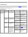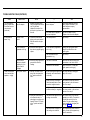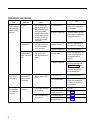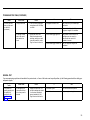
1
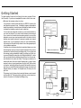
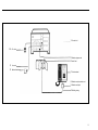
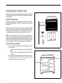
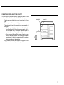
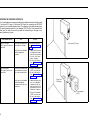
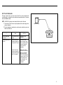
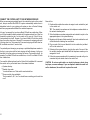
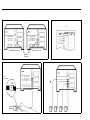
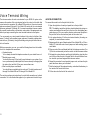
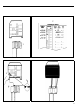
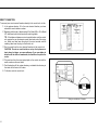
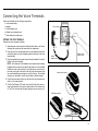
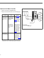
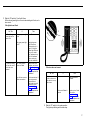
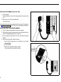
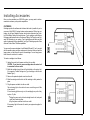
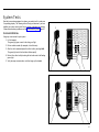
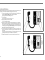
AT&T
MERLIN
®
COMMUNICATIONS SYSTEM
INSTALLATION GUIDE:
MODELS 206 AND 410
Table of Contents
Page
Introduction
2
Getting Started
3
Installing the Control Unit
Position the Control Unit
Set the Control Unit Switches
Connect the Control Unit to the AC Outlet
Prepare the Network Interface
Test the Outside Lines
Connect the Control Unit to the Network Interface
6
6
6
7
8
9
10
Voice Terminal Wiring
Jack Field Connection
Direct Connection
12
12
14
Connecting the Voice Terminals
Prepare the Voice Terminals
Connect Each Voice Terminal to the System
Test Each Voice Terminal for Dial Tone
Attach and Verify the Intercom Numbers
15
15
16
18
18
Installing Accessories
Cartridges
Other Accessories
19
19
20
System Tests
Place an Outside Call
Place an Intercom Call
21
21
22
What’s Next?
23
System Changes
Adding an Outside Line
Adding a Voice Terminal
Moving a Voice Terminal
Changing Touch-Tone/Rotary Service
Upgrading from Model 206 to Model 410
24
24
24
24
24
25
Troubleshooting
Troubleshooting Table
General Test
26
26
29
Appendix A: Interference Information
30
Appendix B: FCC Registration and Repair Information
30
Index
31
1
Introduction
This installation guide tells you how to install and test your MERLIN ® communications system, Model 206 or 410. It leads you step by step through system
installation, from a pre-installation checklist to system tests. You should perform the steps in the order in which they are presented because many of the
earlier steps prepare the system for later steps.
When you complete the steps in this guide, see the administration manual that
came with your system for programming and administration instructions. Your
system may not be fully operable until you have programmed and administered it.
This guide includes the following sections:
●
●
●
●
●
●
●
●
●
Getting Started describes how to prepare for system installation.
Installing the Control Unit explains how to set up and connect the
system’s control unit.
Voice Terminal Wiring provides instructions for connecting the system
wiring.
Connecting the Voice Terminals explains how to connect your voice terminals (MERLIN system telephones) to your system.
Installing Accessories suggests some accessories you may want to consider adding to your system.
System Tests provides tests to help you determine if you’ve installed your
system properly.
What’s Next? refers you to documents that explain how to customize and
use your system to meet your particular business needs.
System Changes explains how to rearrange or alter your system once it
is in place.
Troubleshooting isolates and identifies specific system problems that
could arise during installation, and suggests solutions to basic problems.
The steps in this guide are numbered in order of performance. To visualize a
step as it is described, refer to the drawings accompanying the text. The
numbers in the drawings correspond to the step numbers in the text. The control unit most often pictured in this guide is a Model 410, but the information
presented usually applies to the Model 206 control unit as well. When there
are exceptions, both control units are pictured.
2
Getting Started
This guide assumes the tasks on the following list have been completed. Review
the list carefully. If you have not completed the tasks on the list, do so now.
● Make sure the necessary wiring is in place.
You must have a network interface that links your MERLIN system to the
local telephone company’s lines. A telephone company representative
should have installed your outside lines and labeled the network interface
to indicate the telephone number for each outside line.
You must also have wiring that connects your voice terminal locations to
your control unit location. If your voice terminal locations are close enough
to your control unit to make direct connection practical, you may have
planned to connect your voice terminals directly to the control unit with
modular voice terminal cords and, if necessary, modular voice terminal
extension cords. If you are planning to connect your voice terminals directly
to the control unit, this guide tells you how to do so at the appropriate point
in the installation sequence.
If conditions at your business make direct connections between your voice
terminal locations and your control unit location impractical, then you have
connected the locations through the building wiring. You may have had
the necessary wiring professionally installed, or perhaps you did the wiring yourself following the instructions in the Wiring Installation Kit. In either
case, you should now have building wiring that runs from the voice terminal locations to the control unit location. The wiring runs should end in
modular wall jacks at the voice terminal locations and in a group of jacks
mounted in one or two jack panel boxes (the “jack field”) at the control
unit location. Inside the right door (the one with the handle) of each jack
panel box you should find a label indicating the wiring run number and
endpoint location (for example, “w1 Reception area”) for each jack in the
jack field.
The drawing, top right, shows a direct connection between a voice terminal
and the control unit. The drawing, bottom right, shows a voice terminal connected to the control unit through the building wiring.
Control
unit
Modular voice terminal cord
Voice terminal
Control unit
Jack field
Voice terminal
Building
wiring
3
●
●
Check the items in your shipment against your copy of the order form.
Make sure the items and quantities agree. Save the instructions packed
with components; you may need to refer to them later. And keep the packing boxes just in case you have to return components under warranty.
Get acquainted with the system environment.
Review the planning sheets you drew up when you ordered the system.
Confirm the voice terminal locations, and make sure the control unit location meets the following environmental standards:
— Operating temperature: 40-104°F (4-40°C)
— Humidity: not to exceed 80%
— Ventilation: Leave 6 inches of space above and to the sides of the control unit to prevent overheating. Keep the control unit away from sources
of extreme heat (furnaces, heaters, attics, or direct sunlight). Do not
stack multiple control units in rooms that are not air-conditioned; install them side by side at least 6 inches apart.
— Airborne contamination: Do not expose the control unit to moisture, corrosive gases, dust, chemicals, or similar substances.
●
If your control unit location does not meet these standards, your warranty may
become void.
Become familiar with your MERLIN system.
Review the figure of a simple MERLIN system configuration, opposite
page, and note how components are related to one another.
1 The control unit and the cartridges it contains provide the power
and intelligence for all voice terminals and accessories.
2 Modular jumper cords connect the control unit to the jacks in the
jack field.
3 The jack field serves as an interface between the control unit and
the building wiring.
4 Building wiring ties the whole system together, connecting the
voice terminal locations to the control unit location.
Modular
wall jacks connect the voice terminals to the building
5
wiring.
6 Modular voice terminal cords connect the voice terminals to the
modular wall jacks.
7 Voice terminals provide telephone functions and access to the advanced features in the control unit.
8 The network interface jacks provide connections to the local
telephone company lines.
9 Line cords connect the control unit to the network interface.
10 The ac outlet is the electrical power source for the control unit.
NOTE: Modular jumper cords are identical to modular voice terminal cords.
They have different names in this guide to reflect their different functions
and locations in the system.
●
To comply with FCC regulations, notify your local telephone company of
the following before permanently connecting your system to their lines:
— System registration number: AS 593M-13529-KF-E
— Ringer equivalence number: 0.8A
— Telephone numbers of the lines to which you are connecting your
system.
4
1 Control unit
10 AC outlet
2 Modular jumper cord
3 Jack field
9 Line cord
8 Network interface
7 Voice terminal
6 Modular voice terminal cord
5 Modular wall jack
4 Building wiring
5
Installing the Control Unit
Installation procedures are basically the same for both Model 206 and Model
410. The instructions point out only those differences between the models that
affect installation.
POSITION THE CONTROL UNIT
If you plan to wall mount your control unit, follow the instructions in the booklet
titled CIB 3029 (for Model 206) or CIB 3030 (for Model 410) in your Control Unit
Installation Kit.
5 feet, maximum
Whether you wall mount your control unit or place it on a table or shelf, make
sure it’s within 5 feet of an ac outlet that is not switch-controlled, within 5 feet
of the network interface, and within 6 inches of the jack field, if you have one.
The drawing, right, provides a diagram for positioning the control unit.
6 inches, maximum
NOTE: The ac outlet should be a 117-volt, 60-Hz, 3-prong, third-wire grounded outlet. Proper grounding protects the system against damage from power
surges caused by static discharge and lightning. You should have an electrician check the outlet’s third wire to make sure the outlet is properly grounded.
Power consumption for both models is 40 watts during normal operation.
5 feet, maximum
SET THE CONTROL UNIT SWITCHES
1 Find the Tone/Pulse switch near the top of the center panel on the front
of the control unit.
●
If you have rotary (pulse) telephone service, set the switch to Pulse
(right).
● If you have Touch-Tone signal telephone service, set the switch to
Tone (left).
2 Find the row of switches labeled Ringing on the left panel of the control unit. Set all of them to Yes (up) for now. You may want to reset these
switches later when you customize your system.
1
Tone/Pulse switch
2
Ringing switches
6
CONNECT THE CONTROL UNIT TO THE AC OUTLET
The outlet should not be switch-controlled. Plugging your control unit into a
switch-controlled outlet invites accidental disconnection of the system.
1 Find the power cord attached to the control unit and plug it into the ac
outlet.
The green power light on the control unit goes on.
The red warning light next to the power light comes on momentarily and
then goes off.
● If the green power light does not come on, test the outlet by plugging in a radio or lamp. If the outlet is working properly, your control unit may be faulty. Contact your equipment supplier for
assistance before proceeding with the installation.
● If the red warning light doesn’t blink or remains lit, unplug the power
cord and then plug it in again. If the warning light still doesn’t
operate properly, contact your equipment supplier for assistance
before proceeding with the installation.
2 Unless otherwise instructed, leave the power cord plugged into the ac
outlet throughout the remaining installation procedures.
Warning light
Power light
1
2
AC outlet
7
PREPARE THE NETWORK INTERFACE
Your local telephone company should have installed a network interface with
1-line jacks (RJ11-type) or 2-line jacks (RJ14-type) for connecting your MERLIN
system to your outside telephone lines. The drawing, right, shows the two types
of network interface and the 2-line adapter (267C) for the 2-line network interface jack. The table, below, tells you what to do depending on the type of network interface you have.
And
has a 1-line jack
(RJ11-type) for each outside line
each jack is labeled with
its telephone number
Go on to the next section, “Test the Outside
Lines,” page 9.
each jack is not labeled
with its telephone
number
1. Label each jack with
its telephone number
from the list provided
by the local telephone company.
2. Go on to the next section, “Test the Outsides Lines,” page 9.
each jack is labeled with
the telephone numbers
for its two outside lines
1. Plug a 2-line adapter
(267C) into each jack.
2. Go on to the next section, “Test the Outside Lines,” page 9.
each jack is not labeled
with the telephone
numbers for its two outside lines
1. Label each jack with
the two telephone
numbers for its outside lines from the list
provided by the local
telephone company.
2. Plug a 2-line adapter
(267C) into each jack.
3. Go on to the next section, “Test the Outside Lines,” page 9.
has 2-line jacks
(RJ14-type) for the outside lines
8
Do This
If the Network Interface
1-Line jack (RJ11-type)
2-Line jack
(RJ14-type)
2-Line adapter
(267C)
TEST THE OUTSIDE LINES
This step is optional, but if you have a basic Touch-Tone or rotary telephone with
a modular plug, you should test your outside line connections now. It can save
time and frustration later.
NOTE: A MERLIN system voice terminal will not work for this test.
1 Take a basic Touch-Tone or rotary telephone with a modular plug to the
network interface.
2 Plug the telephone’s modular line cord into each outside line jack, and
listen for a dial tone.
If
And
2
Network interface
1
Do This
you have tested each
outside line
each outside line has a
dial tone
Continue with the
installation.
a line does not have a
dial tone
the jack for that line at
the network interface is
a 1-line jack (RJ11-type)
Have the local telephone company check
the line and the network
interface. Meanwhile,
continue with the
installation.
the jack for that line at
the network interface is
a 2-line jack (RJ14-type)
with a 2-line adapter
Replace the adapter
with another one and try
again for a dial tone. If
the problem remains,
have the local telephone
company check the line
and the network interface. Meanwhile, continue with the
installation.
9
CONNECT THE CONTROL UNIT TO THE NETWORK INTERFACE
When you are assigning outside lines to the outside line jacks on the control
unit, keep in mind that the MERLIN system automatically selects lines in
alphabetical order for your outgoing calls unless you have a Feature Package
and have programmed a different line-selection sequence.
Let’s say, for example, that you have a Model 206 with two outside lines. When
you lift your handset to dial an outside call, the system selects line A (the line
connected to outside line jack A on the control unit) for your call. If line A is busy,
it automatically tries line B. Likewise, if you have a Model 410 with four outside
lines, the system tries lines A through D in sequence for outgoing calls until
it finds an open line. That means line A has more outgoing call traffic than line
B, line B has more than C, and so forth.
You probably want to assign your primary or published telephone number to
the line in your system with the least outgoing call traffic because it is the one
least likely to be busy when an incoming call arrives. That would be line B, for
example, for a Model 206 with two outside lines, or line D for a Model 410 with
four outside lines.
You need the following items from the Control Unit Installation Kit to connect
the control unit to your outside lines at the network interface:
●
●
●
10
System directory
Modular line cords
You should have one 7-foot cord for each outside line.
Green-on-white line cord labels
They’re marked A, B, C, etc. You should have a matching pair for each line
cord.
Now do this:
1 Decide which outside line number to assign to each outside line jack
2
3
4
5
in the control unit.
TIP: The outside line numbers are the telephone numbers listed on
the network interface jacks.
Write the telephone number assigned to each outside line jack in the
appropriate space in the system directory.
Beginning with the pair of labels marked A, label each modular line cord
at both ends with matching line cord labels.
Plug one end of the line cord labeled A into the outside line jack labeled A on the control unit.
Referring to the system directory, plug the other end of line cord A into
the network interface jack labeled with the telephone number you’ve
assigned to line A.
6 Follow the same procedure with the remaining line cords until you’ve
connected all your outside lines to the control unit.
CAUTION: Do not run cords inside or on top of air plenums or ducts, along
hot pipes, or across walkways. If you use staples to attach the cords to a
wall or baseboard, be careful not to pierce the cords.
1
2
Model 410 control unit
Model 206 control unit
Outside
line jacks
Line
cord labels
6
3
A
4
Network
interface
5
11
Voice Terminal Wiring
The intercom number for each voice terminal in your MERLIN system is the
same as the number of the voice terminal jack on the control unit to which that
voice terminal is connected. On a Model 206 control unit, the voice terminal
jacks are numbered 0 through 5. On a Model 410 control unit, the voice terminal
jacks are numbered 10 through 19. If you want a particular intercom number
at a specific location within your business, make a note of the assignment now,
before you begin connecting the voice terminal locations to the system.
You can connect your voice terminal locations to the control unit either of two
ways: (1) directly, with modular jumper cords and, if needed, modular extension cords; or (2) indirectly, through the building wiring to a jack field at the control unit location.
Whichever procedure you use, you need the following items from the installation kit to complete the connections:
●
●
●
System directory
You’ve already recorded the telephone numbers for your outside lines on it.
Modular jumper cords
You should have one 2½-foot cord for each intercom in your system. If you
have a professionally installed jack field, these cords may be hanging from
the jacks in the jack field. If they are, remove them now.
Blue-on-white jumper cord labels
You should have a matched pair for each cord. The label numbers are 0
through 5 for Model 206 and 10 through 19 for Model 410.
The next two sections give instructions for a jack field connection and a direct
connection. Go to the section that applies to your system and do what it says.
12
JACK FIELD CONNECTION
To connect the control unit to the jack field, do this:
1 Open the right door of each jack panel box in the jack field.
TIP: The labeling inside the right door should indicate the wiring run
number and endpoint for each jack in the box. Use this labeling as a
guide when you fill in your system directory and connect the jacks in
the jack field to the voice terminal jacks on the control unit.
2 In the system directory, fill in the voice terminal location (the wiring run
endpoint) for each intercom number.
3 Beginning with the pair of labels marked 0 for a Model 206 or 10 for a
Model, 410, label both ends of each jumper cord with matching jumper
cord labels.
4 Plug one end of the cord labeled with the first intercom number (0 or
10) into the voice terminal jack on the control unit with the same number.
5 Following the system directory and the jack field labeling, plug the other
end of the cord into the jack in the jack field for the voice terminal location to which you have assigned that intercom number.
6 Repeat the procedure for each modular jumper cord, and close the jack
panel box doors when you’re finished.
7 Peel the backing off the system directory, and attach the directory to
the inside of the control unit’s door
8 Fit the door onto the front of the control unit.
2
1
4
3
8
5
10
13
DIRECT CONNECTION
1
To connect your voice terminal locations directly to the control unit, do this:
1 In the system directory, fill in the voice terminal location you have
selected for each intercom number.
2 Beginning with the pair of labels marked 0 for Model 206 or 10 for Model
410, label each cord at both ends with matching labels.
TIP: If the distance between a voice terminal location and the control
unit requires the use of extension cords, label each end of the wiring
run. Attach one label near the plug to the voice terminal and the
matching label near the plug to the control unit.
3 Run the cords from the voice terminal locations to the control unit.
CAUTION: Do not run cords inside or on top of air plenums or
ducts, along hot pipes, or across walkways. If you use staples to
attach cords to walls or baseboards, be careful not to pierce the
cords.
4 Plug each cord into the voice terminal jack on the control unit with the
same number as the cord label.
5 Peel the backing off the system directory, and attach the directory to
the inside of the control unit’s door.
6 Fit the door onto the control unit.
4
2
3
10
Wiring run to intercom 10 location
14
Connecting the Voice Terminals
Each voice terminal has the following components:
● Voice terminal body
● Handset
● Coiled handset cord
● Modular voice terminal cord
● Desk stand and/or wall mount
PREPARE THE VOICE TERMINALS
Voice terminal
3
LINE
Handset
Prepare the voice terminals as follows:
1 Assemble each voice terminal and attach the desk stand or wall mount
following the instructions that come with the components.
2
2
2 Plug one end of the coiled handset cord into the handset and the other
end into the jack next to the handset symbol at the base of the voice
terminal body.
3 Plug the modular voice terminal cord into the jack labeled Line on the
bottom of the voice terminal.
NOTE: If the other end of this modular voice terminal cord is already
plugged into the control unit (as may be the case for a voice terminal
located very close to the control unit), a red light will go on next to a button when you plug the cord into the Line jack on the voice terminal, and
the voice terminal may even begin to ring. Don’t worry. The red light
should go on, and step 5, below, tells you how to stop the ringing.
4 Find the volume control switch on the left side of the voice terminal, and
slide it to the center position.
5 Find the Test/Program (T/P) switch, also on the left side of the voice terminal, and make sure it’s set to the center position. If the switch is set
at T or P, the voice terminal will begin ringing as soon as you plug it in.
Modular voice
terminal cord
Coiled
handset cord
Volume control switch
4
Test/Program switch
5
15
CONNECT EACH VOICE TERMINAL TO THE SYSTEM
1 Place the voice terminal in its designated location.
1
2 Plug the voice terminal into the system in one of the following ways:
If You Have
a direct connection
from the voice terminal to the control
unit
a jack field connection to the control unit
And
the connection requires only a single
modular voice terminal cord
Go on to step 3. You
have already connected the voice terminal to the system in
step 3 of “Prepare
the Voice Terminals,”
page 15.
the connection requires one or more
modular extension
cords
Plug the loose end of
the modular voice terminal cord into the
jack on the extension
cord that terminates
the wiring run from
the control unit location. Then go on to
step 3.
Plug the loose end of
the modular voice terminal cord into the
wall jack at the voice
terminal location.
Then go on to step 3.
A red light comes on next to a button when you plug in the voice terminal.
16
2
Do This
Jack field connection
Direct connection
to control unit
3 Slide the T/P switch to T and hold it there.
All the red and green lights on the voice terminal begin to flash, and a
tone sounds.
If the lights do not flash:
Do This
A. Check the green
power light on the
control unit.
B. Check the wiring
run from the control
unit to the voice
terminal.
If
Then
the green power light
is on
go to B.
the green power light
is off
unplug the power
cord from the ac
outlet and plug it in
again. If the green
power light still does
not go on, contact
your equipment supplier for assistance
before continuing
with the installation.
the wiring connections are stable
make a note of the
problem, and refer to
the Troubleshooting
Table, page 26, after
you’ve completed the
installation.
you find one or more
loose connections
fix the connections. If
the voice terminal
lights still do not
flash, make a note of
it and refer to the
Troubleshooting
Table, page 26, after
you’ve completed the
installation.
3
If the tone does not sound:
Do This
Use the voice terminal’s volume control switch to turn up
the volume.
If
Then
the tone sounds
you’ve solved the
problem.
the tone still doesn’t
sound
make a note of it and
refer to the
Troubleshooting
Table, page 26, after
you’ve completed the
installation.
4 Slide the T/P switch to the center position.
The lights stop flashing and the tone stops.
17
TEST EACH VOICE TERMINAL FOR A DIAL TONE
1 Lift the handset.
The green light goes on next to the shining red light, and you hear a dial
tone.
2 Press one or more of the dial pad buttons.
1
The dial tone stops.
If your system does not respond as described, make a note of it and refer to
the Troubleshooting Table, page 26, after you’ve completed the installation.
2
ATTACH AND VERIFY THE INTERCOM NUMBERS
1 Fill in an intercom number label for each voice terminal.
2 Pry the plastic number card retainer away from its slot below the handset with a straightened paper clip or similar tool.
3 Lay the intercom number label in the slot, and replace the plastic
retainer.
4 Verify the voice terminal’s intercom number:
●
●
●
Touch the fifth button down in the leftmost row of buttons
(Intercom-Ring).
Lift the handset.
Dial the voice terminal’s intercom number.
A busy signal verifies the intercom number.
1
Intercom 15
2
3
18
Installing Accessories
Once you have installed your MERLIN system, you may want to add accessories to enhance your system’s capabilities.
CARTRIDGES
Cartridges provide the software and interfaces that make it possible for you to
use many of the MERLIN system features and accessories. Without any cartridges, you will have Standard Features, which include Automatic Line Selection, Push-Button Dialing, Hold, and Intercom. Type I cartridges, called Feature
Packages, add features such as Conference Calling, Call Transfer, and Outward Call Restriction to your system. Type II cartridges provide Music-on-Hold
and/or Loudspeaker Paging capabilities, and Type III cartridges provide Extra
Alert and Power Failure Transfer capabilities.
You can use the same cartridges in both Models 206 and 410, so if you start
with the smaller system and your needs grow to the extent that you need the
larger system, you don’t have to invest in new cartridges. You can simply move
them from one control unit to another.
To insert a cartridge, do as follows:
1 Unplug the control unit’s power cord from the ac outlet.
CAUTION: Do not insert or remove cartridges when the control unit
is connected to the ac outlet.
2 Match the cartridge type with one of the slot labels on the control unit.
(For example, a Feature Package is a Type I cartridge, so find the slot
labeled Type l.)
3 Remove the protective plastic cover from the slot.
4 Slide the cartridge into the slot until the cartridge is firmly seated in
place.
5 Plug the power cord back into the ac outlet.
The red warning light on the control unit comes on and then goes off after
a few seconds.
If the red warning light does not go out, the cartridge(s) may not be firmly
in place. Try this:
●
●
Unplug the power cord, pull each cartridge from its slot, and push
each firmly back into place.
Plug the power cord back into the ac outlet.
If the warning light still remains lit, contact your equipment supplier for
assistance.
19
OTHER ACCESSORIES
You can enhance your system by adding accessory equipment. Accessories
such as Extra Alert horns, Loudspeaker Paging, and Power Failure Transfer
telephones require additional cartridges. General Purpose Adapters for your
voice terminals allow you to connect modems, autodialers, cordless phones,
and other extension phones. You can also connect headsets and Hands-Free
Units to your voice terminals.
A 34-button deluxe voice terminal used with an accessory requires a Voice Terminal Power Supply, as does a voice terminal more than 1000 feet from the control unit.
To add these and other accessories to your system, follow the instructions that
come with the components.
20
System Tests
Now that your system equipment is in place, you need to test it to make sure
it’s operating properly. The following tests will help you determine if you have
installed your system correctly and if all your system components are working.
If these tests reveal any problems, see the Troubleshooting Table, page 26.
1
PLACE AN OUTSIDE CALL
Using any voice terminal in your system:
1 Lift the handset.
The green light goes on next to the shining red light.
2 Dial an outside number (for example, a friend’s home).
2
3 After the call is answered, place the call on hold by touching Hold.
The green light next to the line button flashes rapidly.
4 Return to the call on hold by touching the line button next to the flashing
green light.
5 Verify two-way communication, and then hang up the handset.
4
5
3
21
PLACE AN INTERCOM CALL
Make this test call from one voice terminal to another voice terminal in your
system. Have someone available to answer the intercom call.
1 From a voice terminal, touch the fifth button down in the leftmost row
of buttons (Intercom-Ring) without lifting the handset.
The red light next to the button goes on.
2 Lift the handset.
The green light next to the button goes on.
3 Dial your partner’s intercom number.
You hear intermittent ringing.
1
2
3
4 Wait for your partner to answer before speaking into your handset.
When the call comes through on the called voice terminal, three short
rings sound, the red light glows steadily next to the fourth button down
in the leftmost row of buttons (Intercom-Voice), and the corresponding
green light flashes until the handset is lifted.
5 When your partner lifts the handset at the called voice terminal, verify
two-way communication, and then hang up the handsets at both voice
terminals.
The lights on both voice terminals go out, and the red light goes on next
to the third button down in the leftmost row of buttons.
6 Repeat this procedure for every voice terminal you want to test.
4
5
22
What’s Next?
Now that your MERLIN system is installed, you need to program it to meet your
business needs. If you have standard features, refer to the Standard Features
User’s Guide: Models 206, 410 and 820. If you have a Feature Package, refer
to the administration manual that comes with the Feature Package to learn how
to customize the system to meet your business needs. Then, review the user’s
guide that also comes with the Feature Package to learn how to use the
MERLIN system custom features.
This installation guide contains information about system changes and
troubleshooting. Keep it for later reference.
23
System Changes
Your MERLIN communications system is designed so that you can make
system changes quickly and easily. You can increase your system’s capacity
simply by adding outside lines and voice terminals to a maximum of 2 lines and
6 voice terminals for Model 206, and 4 lines and 10 voice terminals for Model
410. You can increase the system’s capabilities by adding cartridges and accessories. Modular plugs on much of the system wiring and the labels on key
components make it easy for you to reorganize the system in the event of office rearrangements. If your needs increase so much that you need a larger
system, you should be able to use many of the components from your present
system in your new MERLIN system, which should mean considerable
savings.
2 Assemble each new voice terminal, and connect it to the system according to the instructions in “Connecting the Voice Terminals,” page 15.
3 Record the addition in your system directory.
MOVING A VOICE TERMINAL
You can easily move a voice terminal from one location to another without having to reprogram the voice terminal.
To move a voice terminal:
1 Make sure the necessary wiring is in place (see “Getting Started,” page
3, and “Voice Terminal Wiring,” page 12).
The following are the most common system changes.
2 Unplug the voice terminal at its old location, and plug it in at the new
location.
ADDING AN OUTSIDE LINE
3 Change the connection at the control unit location:
If your MERLIN system becomes so busy that people frequently must wait to
make calls, you may want to add an outside line to your system. If you have
a Model 206, it can support two outside lines. If you have a Model 410, it can
support up to four.
●
1 Have your local telephone company add the outside line(s) and network
interface jack(s) to those you already have in place.
●
2 Obtain a modular line cord for each outside line you are adding.
3 Unplug the control unit power cord from the ac outlet.
4 Follow the instructions for “Prepare the Network Interface,” page 8 and,
“Connect the Control Unit to the Network Interface,” page 10.
5 Label a new line button on each voice terminal that will have access
to the new line. See your administration manual for more detailed information on how to assign an outside line to a voice terminal and which
button to label.
6 Record the change in your system directory.
ADDING A VOICE TERMINAL
You can easily add more voice terminals to your MERLIN system as your
business and communication demands increase. A Model 206 can support up
to six voice terminals; a Model 410 can support up to ten.
1 See that the necessary wiring, jacks,and modular voice terminal cords
are installed between the control unit and the new voice terminal location. (See “Getting Started,” page 3, and “Voice Terminal Wiring,” page
12.)
24
If you have a jack field, unplug the jumper cord labeled with the
voice terminal’s intercom number from the jack in the jack field for
the voice terminal’s old location, and plug it into the jack for its new
location. You do not have to change any labels in the system. Simply record the change of location in the system directory.
If you have a direct connection from the new location to the control unit, find the modular cord that terminates the wiring run from
the voice terminal’s new location to the control unit, and plug that
cord into the voice terminal jack in the control unit with the voice
terminal’s intercom number. This procedure for a direct connection requires you to relabel both ends of the wiring run between
the new location and the control unit with the voice terminal’s intercom number and record the change in the system directory. But
you do not have to reprogram the voice terminal.
CHANGING TOUCH-TONE/ROTARY SERVICE
If you are changing your telephone service from rotary (pulse) to Touch-Tone:
●
Set the Tone/Pulse switch on the control unit to Tone (left).
If you are changing your telephone service from Touch-Tone to rotary (pulse):
●
Set the Tone/Pulse switch on the control unit to Pulse (right).
UPGRADING FROM MODEL 206 TO MODEL 410
If your needs expand beyond the capacity of your Model 206 system, you can
easily install a Model 410 system in its place. You can reuse the cartridges, voice
terminals and accessories that came with your Model 206.
1 Have your local telephone company add outside line(s) and network
interface jack(s) to those you already have. If you have building wiring
with modular jacks, have additional building wiring professionally installed, or install it yourself using the Wiring Installation Kit.
2 Obtain the following components:
8 Plug your original line cords into the control unit line jacks that match
the cords’ labels.
9 Label new line cords at both ends with the letters associated with the
empty control unit line jacks.
10 Assign new intercom numbers to your voice terminals; 10 through 19
are the available intercom numbers with Model 410.
11 Label the modular voice terminal cords with their new intercom
numbers.
Model 410 control unit
Line cords and line cord label pairs for each new wiring run
Additional voice terminals
Modular voice terminal cords and terminal cord labels for each
new voice terminal.
12 Plug your original modular voice terminal cords into the voice terminal
3 Unplug the Model 206 power cord from the ac outlet.
4 Unplug all the modular voice terminal cords and line cords from the
tions. Add new intercom labels to voice terminals. Follow the instructions in “Connecting the Voice Terminals,” page 15.
15 Fill out a new system directory and attach it to the control unit door.
●
●
●
●
Model 206 control unit.
NOTE: Before unplugging the cords, make sure they are accurately
labeled. Also, consult your system directory to make sure it is accurate.
5 Slide the cartridges out of the control unit.
6 Remove the Model 206 control unit and put the Model 410 control unit
jacks that match the cords’ labels.
13 Install your new voice terminal wiring following the instructions in
“Voice Terminal Wiring,” page 12.
14 Assemble your new voice terminals and place them in their new loca-
16 Refer to “What’s Next,” page 23, to find out where you can learn how
to administer and program your new Model 410 system to meet your
individual business needs.
in its place.
7 Insert the cartridges into the new control unit following the instructions
described in “Installing Accessories,” page 19.
CAUTION: Do not insert or remove cartridges when the control unit
power cord is plugged into the ac outlet.
25
Troubleshooting
Refer to the following table if you have trouble with your MERLIN system. Identify the symptom in the “Trouble” column of the table, and perform the recommended steps to isolate and correct the problem. If you are unable to identify a particular problem, perform the general test on page 29 before calling your equipment supplier for help. Once you have programmed and administered your system, you may want to obtain the Service and Maintenance Manual: Models 206,
410, and 820 for additional information on troubleshooting your system.
TROUBLESHOOTING TABLE
Trouble
Possible Cause
You have difficulty
placing outside calls
from more than one
voice terminal.
Incorrect Tone/Pulse
setting
1. Check the Tone/Pulse switch
setting on the control unit.
If
Then
the switch is set to Pulse and
you have Touch-Tone telephone
service
set the switch to Tone.
the switch is set to Tone and you
have rotary (pulse) telephone
service
set the switch to Pulse. This corrects the setting but does not solve
this problem. Go to step 2.
the switch is set for the appropriate telephone service
go to step 2.
Call Restriction
feature activated on
the malfunctioning
voice terminals
2. Refer to the administration
manual to learn how to administer the Call Restriction
feature.
the feature is activated on the
malfunctioning voice terminals
deactivate the feature following the
instructions in the administration
manual.
the feature is not activated on
the malfunctioning voice
terminals
go to step 3.
Faulty MERLIN
system components
3. Try to place both outside and
intercom calls from several
voice terminals.
the trouble appears on intercom
calls or the trouble appears on
only one voice terminal
the trouble is caused by a component in your system. Refer to the
other tests in this table to identify
the source of the problem.
the trouble appears only on outside calls
go to step 4.
the trouble appears on the basic
telephone, and the interface
uses a line adapter
go to step 5.
the trouble appears on the basic
telephone, and the interface
does not have a line adapter
your outside telephone lines are
faulty. Report the trouble to your
local telephone company
representative.
Faulty telephone
company wiring
26
Do this
4. At the control unit location,
unplug the line cords from
the network interface, and in
their place plug in a basic
telephone. (Do not use a
MERLIN system voice terminal.) Try to place an outside call from each network
interface jack.
TROUBLESHOOTING TABLE (CONTINUED)
Trouble
Possible Cause
Do this
You have difficulty
placing outside calls
from more than one
voice terminal.
(continued)
Faulty network interface line adapter
5. Replace the network interface line adapter with another
one. Plug the basic
telephone into each of the
jacks, and try to place an outside call.
A voice terminal
doesn’t ring.
Volume control
switch
Voice terminal programmed not to ring
There is trouble with
voice terminal lights,
speaker, or ringing.
If
Then
the trouble still appears on the
basic telephone
your outside telephone lines are
faulty. Report the trouble to your
local telephone company
representative.
the trouble does not appear on
the basic telephone
the old line adapter is faulty.
Replace it with a new line adapter.
1. Check the volume control
setting on the voice terminal.
Slide the switch to a higher
setting.
the trouble persists
go to step 2.
2. Refer to the user’s guide to
learn how to program ringing
options.
voice terminal is programmed
not to ring
change the ringing option according to the instructions in the
user’s guide.
the voice terminal is programmed to ring
go to step 3.
the feature is activated
deactivate the feature following the
instructions in the User’s Guide.
the feature is not activated
refer to the test for “Trouble with
lights, speaker, and ringing.”
all the red and green lights flash
alternately, and a tone sounds
continually
the voice terminal is working properly. Go to step 3.
some (but not all) of the lights
flash continually and/or a tone
sounds at irregular intervals
the trouble is caused by either the
voice terminal or the cord connection. Go to step 2.
all lights are off and a tone
sounds continually or irregularly
the trouble is either the control unit,
the voice terminal, or the cord connection. Go to step 2.
the same trouble appears on the
working voice terminal
the malfunctioning voice terminal
probably is not faulty. The trouble is
in either the control unit or the
cables. Plug the malfunctioning
voice terminal into its original jack
and go to step 3.
the trouble does not appear on
the working voice terminal
the malfunctioning voice terminal is
faulty. Contact your equipment supplier for assistance.
Do Not Disturb
feature is activated
(applies only if you
have a Feature
Package)
3. Refer to the user’s guide that
came with the Feature
Package.
Faulty voice terminal
1. Slide the T/P switch on the
side of the voice terminal to
the T position and hold it
there.
2. Unplug the malfunctioning
voice terminal, and in its
place plug in a working voice
terminal. Slide its T/P switch
to the T position and hold it
there.
27
TROUBLESHOOTING TABLE (CONTINUED)
Trouble
There is trouble with
voice terminal lights,
speaker, or ringing.
(continued)
Possible Cause
Control unit
Cord connections
Inadequate power
supply to the control
unit
28
A voice terminal
rings constantly.
Voice terminal T/P
switch is not set in
center position
All voice terminals
have no lights and
no dial tone.
Control unit
Do this
Then
If
the trouble still occurs
the problem is caused by your control unit. Call your equipment supplier for assistance.
the trouble no longer occurs
the trouble is caused by one of the
cords running to the malfunctioning
voice terminal. Go to step 4.
the trouble still occurs
the cause is inadequate power to
the control unit Go to step 5.
the trouble no longer occurs
you’ve found the faulty cord.
the trouble remains
the problem is caused by your control unit or the building wiring. Call
your equipment supplier for
assistance.
the trouble no longer occurs
you need one or more Voice Terminal Power Supply units. Refer to
“Installing Accessories,” page 19.
Call your equipment supplier. Leave
accessories unplugged until you
have the necessary power.
it is set at either T or P
slide it to the center position.
it is in the center position
your voice terminal is faulty.
Unplug it from the modular jack
and contact your equipment supplier for assistance.
1. Check the green power light
on the control unit.
the green power light is on
go to step 2.
the green power light is off
go to step 4.
2. Check the red warning light
on the control unit.
the red warning light is off
go to step 3.
the red warning light is on
go to step 4.
3. Go to the control unit and
locate the intercom jacks for
both the malfunctioning and
working voice terminals.
Unplug both from the control
unit, and replug both into the
other’s jack. See if the trouble occurs on the working
voice terminal.
4. Replace each cord, one at a
time, and test the malfunctioning voice terminal.
5. Unplug some of the accessories connected to your
system.
Check the position of the T/P
switch.
TROUBLESHOOTING TABLE (CONTINUED)
Trouble
All voice terminals
have no lights and
no dial tone.
(continued)
Possible Cause
Faulty power outlet
A cartridge is loose
and/or the control
unit needs to be
reset.
Do this
If
Then
3. Test the outlet by plugging in
an appliance such as a lamp
or a radio.
the appliance doesn’t work
the outlet is faulty or controlled by a
wall switch.
the appliance works
the control unit is faulty. Call your
equipment supplier for assistance.
4. Unplug the control unit.
Remove and replace each
cartridge, making sure each
is securely seated in its slot.
Plug the control unit back in.
the red warning light goes out
the problem is solved. One of the
cartridges was not securely in
place and/or the control unit
needed to be reset.
the red warning light remains on
call your equipment supplier for
assistance.
GENERAL TEST
If you are experiencing a problem not described in the previous tests, or if none of the tests reveal a specific problem, try the following procedure before calling your
equipment supplier.
Trouble
Possible Cause
The system isn’t
working properly and
the trouble isn’t
described in the
Troubleshooting
Table.
A cartridge may be
loose and/or the control unit may need to
be reset.
Do this
Unplug the control unit. Pull
out each cartridge and reinsert
it, so that each cartridge is
securely seated in its slot.
Plug the control unit back in.
If
Then
the trouble is gone
you have corrected the problem.
the trouble remains
call your equipment supplier.
29
Appendix A: Interference
Information
Appendix B: FCC Registration
and Repair Information
According to Federal Communications Commission (FCC) Rules, you need to
know that:
● This equipment generates, uses, and can radiate radio frequency energy
and, if not installed and used in accordance with this installation guide,
may cause interference to radio communications.
● The equipment has been tested and found to comply with the limits for
a Class A computing device pursuant to Subpart J of Part 15 of FCC Rules,
which are designed to provide reasonable protection against such interference when operated in a commercial environment.
● Operating this equipment in a residential area is likely to cause interference, in which case the user, at his or her own expense, will be required to take whatever measures may be required to correct the
interference.
This equipment is registered with the FCC in accordance with part 68 of its
Rules. In compliance with the Rules, you are to be advised of the following:
● Means of Connection: Connection of this equipment to the telephone network must be through several standard network interface jacks USOC
RJ11C or RJ14C. You can order these from your local telephone company.
This equipment may not be used with party lines or coin telephone lines.
● Notification of the Local Telephone Company: Before connecting this
equipment, you or your equipment supplier must notify your local
telephone company’s business office. Tell them the:
— Telephone numbers you will be using with this equipment
— Equipment’s registration number and the ringer equivalence
number (REN)
●
●
●
●
30
You must notify your local telephone company if and when this equipment
is permanently disconnected from the line(s).
Installation and Operational Procedures: This guide and the administration manual contain information about installation and operational
procedures.
Repair Instructions: If you experience trouble because your equipment
is malfunctioning, the FCC requires that the equipment not be used and
that it be disconnected from the network until the problem has been corrected. Repairs to this equipment can only be made by the manufacturers,
their authorized agents, or by others who may be authorized by the FCC.
Rights of the Local Telephone Company: If this equipment causes harm
to the telephone network, the local telephone company may discontinue
your service temporarily. If possible, they will notify you in advance. But
if advance notice is not practical, you will be notified as soon as possible.
You will also be informed of your right to file a complaint with the FCC.
Your local telephone company may make changes in its facilities, equipment, operations, or procedures that affect the proper functioning of this
equipment. If they do, you will be notified in advance to give you an opportunity to maintain uninterrupted telephones service.
Hearing Aid Compatibility: The custom telephone sets for this system are
compatible with inductively coupled hearing aids as prescribed by the
FCC.
Index
AC Outlet, 4, 5, 6, 7
Accessories, 19, 20
Autodialer, 20
Extra Alert, 19, 20
Hands-Free Unit, 20
Headset, 20
Voice Terminal Power Supply, 20
Administering the MERLIN System, 2, 6, 23, 24
Airborne Contamination, 4
Building Wiring, 3, 4, 5, 12, 25
Call Transfer, 19
Cartridges, 4, 19, 24, 25
Conference Calling, 19
Control Unit, 2 - 7, 10 - 15, 19, 24, 25
Cartridges, 4, 19, 24, 25
Environmental Requirements, 4
Installing, 6 - 11
Positioning, 6
Power Light, 7
Switches, 6
Wall Mounting, 6
Warning Light, 7
Control Unit Installation Kit, 6, 10, 12
Customer Information Booklets (CIBs), 6
Desk Stand, 15
Direct Connection, 12, 14, 16
Extra Alert, 19, 20
Feature Packages, 10, 19, 23
Federal Communications Commission (FCC), 4, 30
FCC Rules, 4, 30
General Purpose Adapter, 20
General Test, 29
Grounding, 6
Hands-Free Unit, 20
Handset, 15
Handset Cord, 15
Headset, 20
Hold, 19
Humidity, 4
Installing the Control Unit, 6 - 11
Inserting a Cartridge, 19
Intercom, 18, 19, 22
Intercom Number Labels, 18
Intercom Numbers, 12, 13, 18
Jack Field, 3, 4, 5, 6, 12, 13, 16
Jack Field Connection, 3, 12, 13, 16
Jack Panel Boxes, 3, 12, 13
Jumper Cords, 4, 5, 12, 13
Labels, 3, 10, 11, 12, 13, 24, 25
Lightning, 6
Lights, 7, 16, 17, 18, 21, 22
Power Light, 7
Voice Terminal Lights, 16, 17, 18, 21, 22
Warning Light, 7
Line Cords, 4, 5, 10, 11
Local Telephone Company, 4, 8, 30
Modems, 20
Modular Jumper Cords, 4, 5, 12, 13
Modular Line Cords, 4, 5, 10, 11
Modular Voice Terminal Cords, 3, 4, 5, 14, 15, 16
Modular Voice Terminal Extension Cords, 3, 14, 16
Modular Wall Jacks, 4, 5, 16
Music-on-Hold, 19
Network Interface Jacks, 4, 5, 6, 8, 9, 10, 11, 24, 25, 30
1-Line, 8, 30
2-Line, 8, 30
Operating Temperatures, 4
Outside Line Jacks, 9, 10, 11
Outside Lines, 4, 9, 10, 11
Outward Call Restriction, 19
Paging, 20
Power Accessories, 20
Power Consumption, 6
Power Cord, 7
Power Failure Transfer, 19
Power Surges, 6
Programming Instructions, 23
Pulse (Rotary) Service, 6, 24
Push-Button Dialing, 19
Ringer Equivalence Number (REN), 4, 30
Rotary (Pulse) Service, 6, 24
Standard Features, 19
Automatic Line Selection, 19
Push-Button Dialing, 19
Hold, 19
Intercom, 18, 19, 22
Static Discharge, 6
System Changes, 24, 25
System Directory, 10, 11, 12, 13, 14
System Labeling, 3, 10, 11, 12, 13, 14, 24, 25
System Registration Number, 4, 30
System Tests, 21, 22
System Wiring, 3, 4, 5, 10 - 16
Telephone Numbers, 8, 10, 11
Test/Program (T/P) Switch, 15, 17
34-Button Deluxe Voice Terminal, 20
Tone/Pulse Switch, 6, 24
Touch-Tone Service, 6, 24
Troubleshooting Table, 26 - 29
2-Line Adapter, 8
Upgrading to Model 410, 25
User’s Guide, 23
Ventilation, 4
Voice Terminal Jacks, 12, 13, 14, 21, 22, 24
Voice Terminals, 2, 45, 12 - 18
Handset, 15
Handset Cord, 15
Headset, 20
Lights, 16, 17, 18, 21, 22
Line Jack, 15
Modular Voice Terminal Cord, 4, 5, 14, 15, 16
T/P Switch, 15, 17
Volume Control Switch, 15
Wall Mount, 15
Voice Terminal Extension Cords, 3, 14, 16
Voice Terminal Power Supply, 20
Wall Jacks, 4, 5, 16
Warning Light, 7
Warranty, 4
Wiring Runs, 3, 12, 13, 14
31
AT&T
MERLIN is a registered trademark of AT&T
© Copyright 1986 AT&T. Printed in U.S.A.
518-600-000 IS
July 1986
Issue 5