1
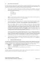
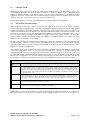
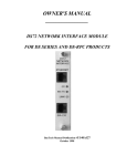
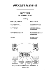
Addendum to Owners Manual
DS73 & DS73TP REMOTE NETWORK COMMUNICATIONS MODULE
1
GENERAL INFORMATION
The DS73 and DS73TP are network communications modules that support remote access to TCP/IP ethernet
networks by using the DS-Series Data Switch equipped with a modem module. Remote users can dial into the DSSeries unit and connect to network hosts from anywhere at any time. Remote workstations and PC’s connect to the
DS73 or DS73TP using a dial-up PPP sessions. This offers dial-up users a low-cost IP network link suitable for
remote access to the network.
The DS73 will automatically detect either 10BASE2 (BNC connector) or 10BASE-T (8-pin modular connector) network
activity. The DS73 supports Ethernet II and Ethernet SNAP frame types automatically, eliminating concern about
DLC compatibility. No configuration or jumpers are necessary.
2
SPECIFICATIONS
PROTOCOLS: PPP, TCP/IP, ARP & ICMP
NETWORK INTERFACE: Ethernet; IEEE 802.3 compliant, 10BASE2 (thin coax,
BNC) and 10BASE-T (twisted pair, RJ-45). Automatic media and frame selection.
FRAME TYPES: Ethernet II & SNAP
SPEEDS: 10 mbps
BUFFER SIZE: 256 KB
SECURITY: Password protected log-on procedure
INDICATORS: Green LED - Link integrity
Red LED - RX/TX
Red LED - Connection status (CX)
POWER REQUIREMENTS: Supplied by DS-Series base unit.
@ 25 degrees, +5 VDC, 300 mA
ENVIRONMENT:
Operating Temperature Range: 0° to 70° C.
Storage Temperature Range: -40° to 80° C.
Humidity: 5 to 95% RH.
BayTech Addendum Publication No. Z140A186
Reference BayTech Manual Publication No. U140E121-03
Page 1 of 10
3
CABLING
CAUTION: Power should be removed anytime cables are installed.
3.1
10BASE2 (COAX) CONNECTION
The 10BASE2 port of the DS73 module connects to any BNC connector on the network cable. BayTech provides a
T-connector for this purpose. Please see the figure below.
3.2
10BASE-T
If your network uses 10BASE-T,
45 cable between the RJ-45 port
modular port is defined as DTE
3 is RD+, and Pin 6 is RD-). Most
straight cable type. The LINK
panel and at the connected port
is a good connection between the
(MODULAR) CONNECTION
DS73 Connection to Network
4
OPERATION
4.1
PROGRAMMABLE FEATURES
4.1.1
IP ADDRESS
RJ-45 connectors, connect an RJand the network hub.
The
(i.e., Pin 1 is TD+, Pin 2 is TD-, Pin
RJ-45 network hubs will require a
(link integrity) LED on the back
on the hub will illuminate if there
DS73 and the hub.
The IP Address is the network address for the DS73 module. The IP Address consists of four bytes with each byte
ranging from 0 to 255 decimal. This parameter must be programmed before the DS73 can be accessed on the network.
The factory default IP Address is 0.0.0.0.
4.1.2
SUBNET MASK
The Subnet Mask is a bit mask that identifies the network portion of the IP address, allowing the DS73 to determine
whether to send a packet directly to the client or to a gateway. The Subnet Mask consists of four bytes with each
byte ranging from 0 to 255 decimal. This parameter must be programmed before the DS73 can be accessed on the
network. The factory default Subnet Mask is 0.0.0.0.
4.1.3
GATEWAY
The Gateway is the address of a router for connection to other networks. The Gateway address consists of four
bytes with each byte ranging from 0 to 255 decimal. The factory default Gateway address is 0.0.0.0.
4.1.4
SELECT CODE
The Port Select Code is sent as part of a select sequence by the host terminal to the DS73 module in order to select
the network host to issue configuration or data commands. The port select code is a programmable ASCII character
string that can range from 1 to 8 characters. The Operator's Manual describes how the port select code is used to
select a specific module or the main board of an DS-Series unit.
4.1.5
PASSWORD
The DS73 Password, if enabled, is required of all users who attempt to access the DS73. The Password consists of an
ASCII character string with a maximum length of 8 characters. The factory default Password is BTA.
4.1.6
USER INTERFACE
User Interface is used to enable or disable the "welcome message" that is sent when a workstation establishes a
connection to the DS73. User Interface is also used to enable or disable the login procedure. The welcome message
and login procedure are enabled by default.
BayTech Addendum Publication No. Z140A186
Reference BayTech Manual Publication No. U140E121-03
Page 2 of 10
4.2
DS73 and DS73TP CONNECTION
The DS73 and DS73TP module requires a physical network connection to perform PPP sessions with the network
host. The DS73 supports 10BASE2 or 10BASE-T Ethernet connections with Ethernet II or 802.3 SNAP framing. Use
the following procedure to access the DS73 modules through the DS-Series Host module:
1.
Open a session to the DS73 module using any workstation TELNET client or ephemeral. You will be
presented with a welcome screen (if enabled) and a login prompt (if enabled) upon successful establishment
of the session similar to the following:
DS-Series DS73
Unit: 1 Module: 1
F 1.05, copyright (c) 1995
Bay Technical Associates
To login, enter password.
Login:
NOTE: You will not get the welcome message and/or the login prompt if either one of these options are
disabled in configuration mode (see Section 5.7 of this addendum).
2.
Enter the password at the login prompt (if enabled).
3.
If the login procedure is enabled, you will receive a "Login Successful" message and a prompt to enter a
selection if the password is successfully entered. At this point, you may configure modules, connect to
ports, receive messages, etc.. See Section 4.5 of this addendum for a summary of DS73 commands.
Refer to the Operator's Manual for operation information concerning the 4-port serial peripheral
communications modules DS74. The DS73 can route data from a peripheral communications module
operating in Immediate Message mode or Immediate Data mode to one and only one network workstation.
A network workstation must send a command to the DS73 module to receive messages or data. This
command consists of the port select code ($BT - default), capital "I", and Carriage Return or Line Feed.
For example, if using the default port select code, send $BTI<cr> where <cr> is Carriage Return. If a
workstation issues this command and another workstation is currently receiving immediate mode data, the
requesting workstation will receive the message "Immediate Mode in use".
The DS73 will send the message "Command/configuration mode in use" to a workstation that attempts to
access command mode of a module while another workstation is currently in command mode for that
module. The requesting workstation will not be able to place a module into command mode until the other
workstation either issues a disconnect command ($BT<cr>) or makes a connection to a specific peripheral
communications port. See Section 4.6 of this addendum for a summary of the various DS73 messages.
4.
A host connection to the DS73 is terminated by sending the port select code ($BT - default), capital "X",
and Carriage Return or Line Feed. For example, if using the default port select code, send $BTX<cr>
where <cr> is Carriage Return.
4.4
RESOURCE RELEASE FUNCTION
Circumstances may arise when it may be necessary to terminate a connection remotely without having to reset the
unit. For example, this situation will occur if a network user does not terminate a port connection to a DS74 port.
Connection termination may be accomplished using the Resource Release function. There are 3 specific methods to
accomplish this function. These are described below (assuming the default select code of "$BT" is used):
$BTRI<cr>
Causes the Immediate Receive mode to be released.
$BTRC<cr>
Causes the Command/Configuration mode to be released (except if user is connected to
the Service Port).
$BTRm,p<cr> Causes the module, port as specified by "m,p" to be released.
4.5
COMMANDS
The DS73 requires that certain commands be issued to make or break network connections or connections to
peripheral modules. These commands are summarized in the table below.
BayTech Addendum Publication No. Z140A186
Reference BayTech Manual Publication No. U140E121-03
Page 3 of 10
NOTE: These commands are illustrated using the default port select code ($BT).
DS73 COMMAND SUMMARY
Command
Description
$BTm,p<cr>
Request to connect to peripheral module "m" port "p". If module m is operating in full duplex mode, full
duplex communication is established when connection is made. Otherwise, the connection is for output only
(from DS73 to the selected module/port).
$BTm<cr>
Request to connect to module "m". Upon connection, the DS73 will enter command mode for the selected
module and the selected module will respond to its command set. The selected module may be configured by
sending "$CONFIG<cr>" after the "$BTm<cr>".
$BTI<cr>
Receive immediate mode data. This will cause the user to receive messages or data from modules configured to
operate in immediate message mode or immediate data mode.
$BT<cr>
Disconnect. Terminates the current operation mode or module/port connection. Network session remains
active.
$BTX<cr>
Network disconnect. Terminates the workstation session. Releases all session resources, such as modes or
ports.
$BTRI<cr>
Locates the user of the Immediate Receive Mode and terminates the session if found, releasing the mode.
$BTRC<cr>
Locates the user of the Command/Configuration mode and terminates the session if found, releasing the mode.
$BTRm,p<cr>
Locates the user of m,p (module,port) and terminates the session if found, releasing the port.
m = desired module number (1 to 16), p = desired port number (1 to 4), <cr> = Carriage Return
BayTech Addendum Publication No. Z140A186
Reference BayTech Manual Publication No. U140E121-03
Page 4 of 10
4.6
MESSAGES
The DS73 generates various messages in response to certain commands/situations as described in the table below.
DS73 MESSAGES
Message
Description
Module "m" not installed
Issued when a user tries to connect to a peripheral module or
port that was not reported as installed to the DS73. Verify that
correct module number was entered. Check module operation
on power-up to verify normal initialization.
Module "m" not responding
Issued when a module was reported as installed, but failed to
respond within 1 second to a connection request from the
DS73. Repeated occurrences of this message indicate a possible
problem with the module. Check module operation on
power-up to verify normal initialization.
Module "m" busy
Issued when a connection request is denied by a module. A
connection is typically denied when a module is already
supporting a connection to another user.
Module "m", port "p" busy
Issued when a port connection request is denied by a module. A
connection is typically denied when a port on the module is
already supporting a connection to another user.
Login successful
Issued when a user completes the login sequence successfully.
Upon the receipt of this message, the user has full access to the
DAC and may issue any valid DS73 command.
Login failed
Issued when user enters erroneous password. Password is case
sensitive and will not tolerate any backspaces or character
deletes.
Immediate Mode in use
Issued when a user tries to enter immediate receive mode (by
entering "$BTI<cr>") and another user is already using the
resource. Immediate receive mode may only be used by one
user at a time.
Command/Configuration Mode in use
Issued when a user tries to connect to a module (not a port) for
command mode or configuration purposes (by entering
"$BTm<cr>") and another user is already using the resource.
Command/Configuration mode may only be used by one user at
a time. This particular message indicates the current user is a
network client.
Command/Configuration Mode in use by Service Port. To
release mode, terminate Service Port connection.
Issued when a user tries to connect to a module and the module
is in use by a user connected to the service port. To free the
resource, the Service Port connection must be terminated from
the device connected to it.
Resource released
Issued when the user of a module or port is successfully located
and the associated process is terminated. See "Resource Release
Function" (Section 4.4 of this addendum).
Resource not released
Issued when the user of a node or port is successfully located,
but the associated process could not be terminated. For
example, if the user wanted to release the
Command/Configuration Mode, but the current user was
connected via the Service Port, the resource would not be
released.
No resource user found
Issued when no open connection could be associated with the
specified mode or port.
Connecting....Connected
Issued to provide status of Telnet Client connection request.
Dots are issued at 1/sec until the connection is established. If
the connection cannot be established because the host fails to
respond, the connection request will time out in about 30
seconds.
Cannot connect to host
Issued when a host refuses to accept or fails to respond to a
connection request.
Host session terminated
Issued when a connection is terminated by either the host or the
client.
BayTech Addendum Publication No. Z140A186
Reference BayTech Manual Publication No. U140E121-03
Page 5 of 10
DS73 MESSAGES
Message
Description
m = module number (1 to 16), p = port number (1 to 4)
BayTech Addendum Publication No. Z140A186
Reference BayTech Manual Publication No. U140E121-03
Page 6 of 10
4.7
LED INDICATORS
Each DS73 has three LED indicators on the rear panel and four LED indicators on the front panel of the base unit
corresponding to the module slot where the DS73 is installed (i.e., Module 1, Module 2, etc.). The LEDs on the
module rear panel are marked as LINK, RX/TX and CX. The green LINK LED illuminates if the DS73 has a good
10BASE-T connection. Failure of this LED to illuminate indicates a physical connection problem only if twisted pair
cabling is being used. The red RX/TX CX LED’s indicates network activity.
The four LED indicators on the front panel of the base unit are used for diagnostics and operation.
4.7.1
DIAGNOSTIC LED INDICATIONS
When the DS-Series DAC unit is reset or powered up, the LEDs on the base unit will go through a scanning
sequence beginning with Module 1 Port 1 and ending with the highest module number Port 4. Then a certain number
of LEDs corresponding to the number of installed modules will stay on for a brief period of time. For example, if six
modules are installed, the LEDs for Module 1 Ports 1 through 4 and Module 2 Ports 1 and 2 will stay on briefly. Next,
the LEDs will scan down beginning with the highest module number Port 4 and ending with Module 1 Port 1. If you
notice one of the LEDs corresponding to the number of installed modules stay on after the LEDs scan down, this
indicates a failure with the corresponding module. For example, if the LED for Module 1 Port 2 stays on after the
LEDs scan down, then Module 2 has a problem.
The DS73 will give diagnostic indications approximately five seconds after completion of the reset/power-up scan.
The first diagnostic indication is a hardware check. If the DS73 hardware checks out, all four DS73 LEDs will flash
once. If a hardware failure is detected, one of the first three LEDs for the DS73 module will flash continuously. If this
happens, you should contact BayTech.
If the hardware check passes, the DS73 will read the configuration parameters from the main board non-volatile RAM.
If the DS73 configuration checks out, all DS73 LEDs will flash once. Therefore, if the DS73 hardware and
configuration checks both pass, you should notice all four LEDs on the DS73 flash twice. If you notice that one of
the DS73 LEDs flashes continuously after the hardware check passes (i.e., after all four DS73 LEDs flash once), this
indicates that a configuration error has been detected. If this happens, the DS73 will not respond to any network
access attempts. Configuration problems can be corrected by programming the indicated parameter as follows:
DS73 CONFIGURATION DIAGNOSTIC LED DESCRIPTION
Flashing
LED
Description
1
Non-volatile Memory Fault. The data stored in the non-volatile RAM for the DS73's location contained an
error. This causes the device in question to be programmed with default parameter information and the IP and
Gateway addresses and the subnet mask will be set to 0.0.0.0. The module will need to be reconfigured and reset
before it can operate. This symptom will occur when the DS73 is installed into a module slot previously occupied
by a different module type.
2
Ethernet Address Fault. If an error occurs in the retrieval of the module's Ethernet address, the address will be set
to all 0s, an invalid address. Before the module can operate, it will need to be programmed with a proper address.
This address cannot be programmed directly by the user. Contact BayTech if this LED symptom occurs.
3
IP Address Fault. When a module is first installed, it will program its IP Address to 0.0.0.0. The IP Address will
need to be programmed before the module can operate.
4
Subnet Mask Fault. When a module is first installed, it will program its Subnet Mask to 0.0.0.0. The Subnet
Mask will need to be programmed before the module can operate.
NOTE: When you power up the DS-Series with a DS73 installed for the first time, the LEDs for Ports 3 and 4 for the
DS73 will flash continuously until you program the IP Address and Subnet Mask (see Section 5) and reset the unit.
BayTech Addendum Publication No. Z140A186
Reference BayTech Manual Publication No. U140E121-03
Page 7 of 10
4.7.2
OPERATION LED INDICATIONS
The DS73 only utilizes the first and the fourth LEDs of the base unit module location during normal operation as
described below.
DS73 OPERATION DIAGNOSTIC LED DESCRIPTION
LED
Description
1
Active Connection. This LED will remain illuminated for about 30 seconds after the last network connection is
terminated.
4
(flashing)
5
Cabling Error. This LED will flash continuously when a transmission attempt fails from a cable or a connection
malfunction. Once this condition is detected, the module will periodically attempt to transmit on the link and
this LED will flash as long as the transmission attempt fails. When the cable problem is corrected, this indication
will cease with no further intervention by the user. However, connections may have been lost and will need to be
checked and reconnected if necessary.
CONFIGURATION
Configuration changes for the DS73 peripheral communications module are made from the service port using the
following procedure:
1.
If configuring from the service port, connect a terminal to the EIA-232 service port and configure the
terminal's serial parameters to 9600 baud rate, 8 word size, 1 stop bit, and no parity. Once the unit is powered
on, the following message will be sent out of the service port:
Bay Technical Associates
Service Port
Firmware Revision 4.15
This same message will be sent to the remote modem once a connection is established with the DS71-MD2
modem.
The DS71-MD2 modem has priority over the EIA-232 service port. When a connection is established
between a remote modem and the service port, the following message will be sent out of the EIA-232 service
port:
Incoming call
Service port access locked out
A terminal connected to the EIA-232 service port is not allowed access to the DS-Series unit while the
service modem has a connection with a remote modem. If a user connected to the EIA-232 service port is
currently communicating with the DS-Series unit and a remote user attempts to access configuration mode
through the service modem, the remote user is not allowed access to the DS-Series unit.
2.
Place the desired module into command mode by sending $BTm<cr> or $BTm<lf> where m is the desired
module number (1 to 16) <cr> is Carriage Return and <lf> is Line Feed.
3.
Access configuration mode by sending $CONFIG<cr>. No characters should be typed between $BTm<cr>
and $CONFIG<cr>.
BayTech Addendum Publication No. Z140A186
Reference BayTech Manual Publication No. U140E121-03
Page 8 of 10
5.1
MAIN CONFIGURATION MENU
The DS73 will respond to the receiving of $CONFIG<cr> with an identification block and a menu of the available
configuration options similar to the following:
DS-Series DS73
Unit: 1 Module: 1
F 1.05, copyright (c) 1995
Bay Technical Associates
IP Address:
Subnet Mask:
Gateway Address:
Select Code:
Ethernet Address:
Client Msg/Login:
Unit Memory (MB)
Active Connections:
0.0.0.0
0.0.0.0
0.0.0.0
$BT
00.C0.48.12.34.56
enabled/enabled
2
2
IP Address............... 1
Subnet Mask.............. 2
Gateway.................. 3
Select Code.............. 4
Password................. 5
User Interface............6
Exit..................... X
>
NOTE: The line showing the amount of memory between the "Client Msg/Login" line and the "Active Connections"
line is displayed only if an M03 memory module is installed.
You can now make whatever changes are necessary by responding to the above menu. The "X" selection (Exit
Configuration) will return you to the operations mode.
5.2
IP ADDRESS
By responding to the Enter selection: message at the end of the main configuration menu with "1" (IP Address), you
can program the IP address. The DS73 will respond with:
Enter IP address in dotted decimal form:
Enter the desired IP address as a series of four numbers separated by periods (e.g., 197.3.14.9) followed by Carriage
Return.
NOTE: The first part of the IP address is determined by assigned network address.
IMPORTANT: The IP address must be programmed before the DS73 module can be accessed on the network. After
programming the IP address, the DS-Series unit must be reset for the new information to take effect.
5.3
SUBNET MASK
By responding to the Enter selection: message at the end of the main configuration menu with "2" (Subnet Mask),
you can program the Subnet Mask. The DS73 will respond with:
Enter Subnet Mask in dotted decimal form:
Enter the desired Subnet Mask as a series of four numbers separated by periods (e.g., 255.255.255.0) followed by
Carriage Return.
IMPORTANT: The Subnet Mask must be programmed before the DS73 module can be accessed on the network.
After programming the Subnet Mask, the DS-Series unit must be reset for the new information to take effect.
5.4
GATEWAY
By responding to the Enter selection: message at the end of the main configuration menu with "3" (Gateway), you
can program the Gateway or router address. The DS73 will respond with:
Enter Gateway address in dotted decimal form:
Enter the desired Gateway or router address as a series of four numbers separated by periods (e.g., 197.3.14.1)
followed by Carriage Return.
IMPORTANT: After programming the Gateway address, the DS-Series unit must be reset for the new information to
take effect.
BayTech Addendum Publication No. Z140A186
Reference BayTech Manual Publication No. U140E121-03
Page 9 of 10
5.5
SELECT CODE
By responding to the Enter selection: message at the end of the main configuration menu with "4" (Select Code), you
can change the port select code to any ASCII character string from 1 to 8 characters. The DS73 will respond with:
Enter Select Code (8 chars max):
Type the desired port select code followed by <ENTER>. The DS73 saves the new port select code permanently in
the non-volatile memory and return to the main configuration menu.
NOTE: The select code is case sensitive. You cannot program the port select code to be $BT from the service port
or service modem.
NOTE: It is not necessary to reset the unit for this option to take effect.
5.6
PASSWORD
By responding to the Enter selection: message at the end of the main configuration menu with "5" (Password), you
can program the DS73 Password. The password is used for security purposes to prevent unauthorized users from
connecting to the DS73 and accessing its functions. The DS73 will respond with a menu similar to the following:
Current password: BTA
Enter Password (8 chars max):
Type the desired password up to eight ASCII characters. Press <ENTER> to return to the main configuration menu.
NOTE: The password is case sensitive. Any non-alphanumeric character including <BACKSPACE> and <DELETE>
or a password greater than eight characters is interpreted as an input error and you will be prompted to enter the
password again.
Terminate the password entry by typing the <ENTER> key. The DS73 will respond with:
Accept password as typed above? (Y/N) :
Press "Y" to accept the new password or "N" to reject it. If you press "N", the DS73 will return to the "Enter
Password" prompt. If you type "Y", the DS73 will return to the main configuration menu.
NOTE: It is not necessary to reset the unit for this option to take effect.
5.7
USER INTERFACE
By responding to the Enter selection: message at the end of the main configuration menu with "6" (User Interface),
you can configure the DS73 to either display or not display the welcome message that is sent to the workstation
when a connection is made to the DS73. You can also enable or the disable the login procedure that follows the
welcome message. The DS73 will respond with:
Enable/Disable Welcome Message? (E/D):
Press "E" to enable the welcome message, "D" to disable the welcome message, or <ENTER> to skip this option. The
DS73 will respond with:
Enable/Disable Login? (E/D):
Press "E" to enable the login procedure, "D" to disable the login procedure, or <ENTER> to skip this option. The
DS73 will return to the main configuration.
NOTE: It is not necessary to reset the unit for this option to take effect.
BayTech Addendum Publication No. Z140A186
Reference BayTech Manual Publication No. U140E121-03
Page 10 of 10
6
GETTING STARTED
Before the DS73 and the DS-Series data switch can be used, there are a few parameters which must be configured by
the user.
First time power-up: When the DS73 is first powered up, it will cycle through its diagnostics until it finds that it has
not been programmed with an IP address or subnet mask. At this point, it should flash its front panel LEDs 3 & 4.
An IP address and subnet mask are minimum requirements for module operation. These parameters are configured
using the following procedure:
1.
Access the DS73 through the Service Port: The DS73 is programmed through the Service Port only. Attach
a 9FRJ45PC-3 or 25FRJ45PC-3 serial adapter to your PC's com port and connect a crossed RJ-45 cable
between the serial adapter and the DS-Series DAC EIA-232 service port. Other terminal devices may require
a different adapter, consult the owner's manual or Bay Tech Technical Support. Once the cable is in place,
invoke a communications program on the PC (e.g., BayTech TERM.EXE) and set the serial parameters for
9600 baud, 8 data bits, 1 stop bit, no parity. The following commands are all case sensitive, so be sure to
enter them accordingly.
Type $BTm<cr> where m is a number corresponding to the DS73's installed location in the unit (1 to 16) and
<cr> is Carriage Return. This number may be determined by locating the module in the unit and reading its
associated module number from the back panel area.
2.
Obtain the DS73's configuration menu: After the module select string has been entered, you should see a
message such as "Requested connection made." After receiving this message, type $CONFIG<cr>. This
will display the DS73's status screen and the main configuration menu.
3.
Program the module's IP address: Type "1" from the main configuration menu (IP Address). You will be
prompted to enter an IP address in dotted decimal form. This consists of 4 numbers between 0 and 255
separated by periods (ex: 200.4.123.17). After typing the desired address, type Carriage Return to enter the
information. The DS73 will return to the main configuration menu.
4.
Program the module's Subnet Mask: Type "2" from the main configuration menu (Subnet Mask). You will
be prompted to enter a subnet mask in dotted decimal form. This parameter is used by the DS73 to
determine if a destination is a local address or one that resides on another subnet. A binary representation
of a properly entered subnet mask will consist of all "1"s in bit locations corresponding to the network
portion of the IP address and all "0"s in bit locations corresponding to the host portion of the IP address.
Observing the same conventions as for the IP address, enter the subnet mask (ex:255.255.255.128) followed
by Carriage Return.
There may be other parameters you wish to configure, such as a gateway/router, but for now, this is enough to get
going. If you wish to change other parameters at this time, consult the relevant sections of this addendum. When
you are finished, type "X" at the main menu to exit configuration. Reset the unit by typing $BTRESET<cr> or by
cycling unit power for the changes to take effect.
After resetting the unit, you should see all 4 module LEDs flash on and off two times and then remain off. This is a
normal initialization indication. After the second LED flash, the module is on line and ready for network access.
Configuration of other modules on the unit may be necessary or desirable, depending on your application and unit
module population. This configuration may be accomplished through the DS73 or the service port. If you need
additional help, call Bay Tech's Technical Support line for assistance in setting up your unit.
BayTech Addendum Publication No. Z140A186
Reference BayTech Manual Publication No. U140E121-03
Page 11 of 10