1
OWNER’S MANUAL
_________________
BAYTECH
M SERIES DAC
including
M3,M4,M6,M9,M16
BASE UNITS
V71,V72TP,V93A
HOST MODULES
V74/V75/V87
4-PORT SERIAL
MODULES
V77/V78/V79/V80/V90
PERIPHERAL DAC
MODULES
V82,M03
ANCILLARY
MODULES
BayTech Manual Publication #U140E111-03
March 1999
i
Telplex, LaserShare, Print Master and TRAN-X are registered trademarks of Bay
Technical Associates, Inc.
IBM, IBM PC, IBM PC/AT, IBM PC/XT are products and registered trademarks of
International Business Machines CorpoHewlett-Packard LaserJet is a product and
registered trademark of the Hewlett-Packard Company.
All products or company names are trademarks of their respective holders.
ii
M SERIES DAC
ABOUT THIS OWNER’S MANUAL
___________________________________________________________________________
ABOUT THIS OWNER’S MANUAL
This document provides information required for installing and operating your Bay
Tech equipment. It should allow the user to connect, power up, and access an
applications menu where peripheral equipment can be controlled. We recommend
reading this manual carefully, while placing special emphasis on correct cabling and
configuration. If you have any problems with your installation, please contact a
BayTech Applications Engineer at 228-467-8231, call toll free from anywhere in the
United States using
1-800-523-2702 or contact us at our Web Site, www.baytechdcd.com.
BayTech manufactures many remote site management products, data switches, data
collection multiplexers, remote power controllers, and peripheral print sharers. If you
would like information on any of these products, please contact BayTech Customer
Service at the numbers previously listed.
Conventions used in this manual include:
CAUTION: This term is used to denote any condition that could possibly
result in physical harm to personnel or damage to equipment.
IMPORTANT: This term is used to denote conditions that could result in
the loss of communications or to highlight the proper functioning of
equipment.
NOTE: This term is used to denote items of interest to the user.
<cr>: Carriage Return or ENTER
The information in this document is subject to change without notice. The statements,
configurations, technical data, and recommendations in this document are believed to
be accurate and reliable, but are presented without express or implied warranty. Users
must take full responsibility for their applications of any products specified in this
document. The information in this document is proprietary to Bay Technical
Associates, Inc.
In the interest of improving internal design, operational function, and/or reliability,
Bay Technical Associates, Inc reserves the right to make changes to the products
described in this document without notice.
Bay Technical Associates, Inc does not assume any liability that may occur due to the
use or application of the product(s) or circuit layout(s) described herein.
This manual replaces BayTech Publication U140E111-02 and includes information
from the following Bay Tech publications:
iii
M SERIES DAC
INTRODUCTION TO THE M SERIES DAC
___________________________________________________________________________
U140E100-02
U140A123-01
U140E101-05
U140E103
U140E104
U140E105
U140E116-02
Z140A181-02
V71 Host Communications Module
V72TP Ethernet Host Communications Module
V74, V75, and V87 4 Port Serial I/O Modules
V77 ADM-1 Module
V78 CRM-1 Module
V79 PDI-1 and V80 PDI-2 Modules
V93A Host Communications Module
V82 PCM-1 Module
We welcome any comments you may have about our products, and we hope that you
will continue to look to BayTech for your data communication needs.
iv
M SERIES DAC
TABLE OF CONTENTS
____________________________________________________________________________
ABOUT THIS OWNER'S MANUAL ............................................... iii
INTRODUCTION TO THE M SERIES DAC.................................. 1
QUICK START.................................................................................... 6
BASE UNIT CABLING.........................................................................7
SERVICE PORT/SERVICE MODEM CABLING.................................................... 7
V71 CABLING......................................................................................8
INSTALLATION ............................................................................... 40
BASE UNIT AND MODULE CONFIGURATION ........................ 44
BASE UNIT CONFIGURATION .........................................................44
HOST MODULE, SERVICE PORT, AND SERVICE MODEM
CONFIGURATION....................................................................................................... 44
HOST MODULE ACCESS ................................................................................. 44
SERVICE PORT OR SERVICE MODEM ACCESS..................................... 45
SET DATE.................................................................................................................. 46
SET TIME................................................................................................................... 46
SET UNIT NUMBER................................................................................................ 47
BASE UNIT DYNAMIC CONFIGURATION COMMANDS......................... 47
V71 HOST MODULE CONFIGURATION...........................................47
MAIN MENU CONFIGURATION............................................................................ 47
STATUS....................................................................................................................... 48
PORT SELECT CODE............................................................................................. 48
SERIAL PORT CONFIGURATION...................................................................... 49
EXIT CONFIGURATION........................................................................................ 51
V72TP HOST MODULE CONFIGURATION.......................................51
MAIN CONFIGURATION MENU............................................................................ 51
IP ADDRESS.............................................................................................................. 52
SUBNET MASK........................................................................................................ 52
GATEWAY................................................................................................................. 52
SELECT CODE.......................................................................................................... 53
PASSWORD............................................................................................................... 53
USER INTERFACE.................................................................................................. 54
ID MSG: MODULE ID MESSAGE.................................................................. 54
LOGIN: LOGIN PROCEDURE......................................................................... 54
IMR: IMMEDIATE MODE MESSAGE QUICK RELEASE...................... 54
CRT: CARRIAGE RETURN TRANSLATION-STRIP LINE FEEDS OR
NULLS..................................................................................................................... 54
MENU: MENU MODE OF OPERATION...................................................... 54
ATTN: MENU ATTENTION CHARACTER................................................ 54
v
M SERIES DAC
TABLE OF CONTENTS
____________________________________________________________________________
HOST CONFIGURATION.................................................................................. 55
REVERSE TELNET OPERATION................................................................... 55
PROGRAMMABLE BREAK............................................................................. 55
DIAGNOSTICS.......................................................................................................... 55
SYSTEM STATUS................................................................................................ 55
INTERNAL BUS STATUS................................................................................. 56
NETWORK STATUS........................................................................................... 56
LOGGED USERS.................................................................................................. 56
EXIT ............................................................................................................................. 57
V74/V75/V87 SERIAL I/O MODULE CONFIGURATION ...................57
MAIN MENU CONFIGURATION............................................................................ 57
STATUS....................................................................................................................... 58
SERIAL PORT CONFIGURATION...................................................................... 59
PORT DEVICE NAME............................................................................................ 61
PORT ID...................................................................................................................... 62
DESIGNATE PORT MODULE LOCATION...................................................... 62
MESSAGE TERMINATE CHARACTER............................................................ 63
MODE OF OPERATION......................................................................................... 63
CONNECT PORT ID ECHO................................................................................... 64
EXIT ............................................................................................................................. 64
V77 ADM-1 MODULE CONFIGURATION .........................................64
MAIN MENU CONFIGURATION............................................................................ 65
MODULE STATUS.................................................................................................. 65
SAMPLING SETUP.................................................................................................. 66
SAMPLING METHOD........................................................................................ 66
SAMPLE START TIME...................................................................................... 67
SAMPLE INTERVAL.......................................................................................... 68
SAMPLE RATE..................................................................................................... 69
NUMBER OF SAMPLES TO AVERAGE....................................................... 69
REPORTING SETUP................................................................................................ 70
REPORTING METHOD...................................................................................... 70
REPORT START TIME....................................................................................... 71
REPORT INTERVAL........................................................................................... 72
ADDRESS............................................................................................................... 72
FORMAT ................................................................................................................ 73
TAG.......................................................................................................................... 73
CHARACTER(S)................................................................................................... 73
CHANNEL INPUT SETUP ..................................................................................... 74
RANGE.................................................................................................................... 74
UNIPOLAR/BIPOLAR........................................................................................ 74
SINGLE ENDED/DIFFERENTIAL.................................................................. 75
ACTIVE CHANNELS .......................................................................................... 75
DYNAMIC CONFIGURATION............................................................................ 76
EXIT ............................................................................................................................. 77
DYNAMIC CONFIGURATION PROCEDURE AND COMMANDS...... 77
vi
M SERIES DAC
TABLE OF CONTENTS
____________________________________________________________________________
AVERAGE COMMAND..................................................................................... 78
REPORTING METHOD COMMAND............................................................. 78
SINGLE ENDED OR DIFFERENTIAL COMMAND.................................. 79
TIME TAG COMMAND..................................................................................... 79
UNIPOLAR/BIPOLAR COMMAND............................................................... 79
VOLTAGE RANGE COMMAND..................................................................... 79
V78 CRM-1 MODULE CONFIGURATION .........................................80
CONFIGURATION MAIN MENU............................................................................ 80
MODULE STATUS.................................................................................................. 80
RELAY OPERATING SETUP................................................................................ 81
LIST CURRENT SCHEDULE............................................................................ 81
CREATE/MODIFY SCHEDULE....................................................................... 82
ENABLE/DISABLE EVENTS ........................................................................... 83
DELETE EVENTS/SCHEDULE........................................................................ 84
REPORTING SETUP................................................................................................ 84
REPORTING METHOD...................................................................................... 84
REPORT START TIME....................................................................................... 85
REPORT INTERVAL........................................................................................... 86
HOST ADDRESS.................................................................................................. 86
TIME TAG.............................................................................................................. 87
TERMINATING CHARACTER(S)................................................................... 87
DYNAMIC CONFIGURATION............................................................................ 88
EXIT ............................................................................................................................. 88
DYNAMIC CONFIGURATION PROCEDURE AND COMMANDS...... 88
REPORTING METHOD COMMAND............................................................. 89
TIME TAG COMMAND..................................................................................... 89
V79 PDI-1 AND V80 PDI-2 MODULE CONFIGURATION..................90
0CONFIGURATION MAIN MENU.......................................................................... 90
MODULE STATUS.................................................................................................. 90
0SAMPLING SETUP................................................................................................ 91
REPORTING SETUP................................................................................................ 92
REPORTING METHOD...................................................................................... 92
REPORT START TIME....................................................................................... 93
REPORT INTERVAL........................................................................................... 94
HOST ADDRESS.................................................................................................. 94
TIME TAG.............................................................................................................. 95
TERMINATING CHARACTER(S)................................................................... 95
DYNAMIC CONFIGURATION............................................................................ 96
EXIT ............................................................................................................................. 96
DYNAMIC CONFIGURATION PROCEDURE AND COMMANDS...... 96
DEBOUNCE DELAY COMMAND.................................................................. 97
REPORTING METHOD COMMAND............................................................. 97
TIME TAG COMMAND..................................................................................... 98
V93A HOST MODULE CONFIGURATION ........................................98
CONFIGURATION MAIN MENU............................................................................ 98
vii
M SERIES DAC
TABLE OF CONTENTS
____________________________________________________________________________
STATUS....................................................................................................................... 98
SERIAL PORT CONFIGURATION...................................................................... 99
PORT DEVICE NAME..........................................................................................100
PORT SELECT CODE...........................................................................................101
ATTENTION CHARACTER................................................................................102
DISCONNECT TIME GUARD ............................................................................102
LOGIN PASSWORD ..............................................................................................102
LOCAL MODEM SETUP......................................................................................103
EXIT ...........................................................................................................................103
ECHO MODE...............................................................................................................104
RING DETECT RESET ..............................................................................................104
MODEM LED INDICATORS...................................................................................104
BASE UNIT AND MODULE OPERATION................................. 105
BASE UNIT USER-PROGRAMMABLE FEATURES .......................................105
BASE UNIT BASIC OPERATION..........................................................................105
BASE UNIT DATA COMMANDS..........................................................................105
BASE UNIT READ TIME (RT) COMMAND..................................................106
BASE UNIT RESET COMMAND.......................................................................106
ECHO MODE...............................................................................................................106
BASE UNIT LED DESCRIPTION...........................................................................107
V71 OPERATION ............................................................................. 107
V71 USER-PROGRAMMABLE FEATURES .......................................................107
V71 PORT SELECT CODE...................................................................................108
V71 SERIAL PORT CONFIGURATION...........................................................108
V71 RESET COMMAND......................................................................................108
V71 TEST COMMAND.........................................................................................108
V71 BASIC OPERATION.........................................................................................108
V72 OPERATION ............................................................................. 109
PROGRAMMABLE FEATURES.............................................................................109
IP ADDRESS............................................................................................................109
SUBNET MASK......................................................................................................109
GATEWAY...............................................................................................................110
SELECT CODE........................................................................................................110
PASSWORD.............................................................................................................110
USER INTERFACE................................................................................................110
V72 HOST CONNECTION .......................................................................................112
REVERSE TELNET OPERATION..........................................................................113
RESOURCE RELEASE FUNCTION ......................................................................114
USER INTERFACE................................................................................................115
MENU MODE/ATTENTION CHARACTER METHOD....................................115
ATTENTION CHARACTER METHOD................................................................115
IMMEDIATE DATA COLLECTION.................................................................117
CONFIGURATION.....................................................................................................117
MODULE CONFIGURATION.............................................................................117
viii
M SERIES DAC
TABLE OF CONTENTS
____________________________________________________________________________
MAIN BOARD CONFIGURATION...................................................................118
MANUAL CONNECTION........................................................................................119
UNIT RESET ................................................................................................................120
MODULE STATUS.....................................................................................................121
SYSTEM STATUS..................................................................................................121
INTERNAL COMMUNICATIONS.....................................................................122
NETWORK INTERFACE......................................................................................122
LOGGED USERS....................................................................................................123
EXIT................................................................................................................................124
LOGOUT .......................................................................................................................124
ASCII STRING COMMAND METHOD................................................................125
MESSAGES ..................................................................................................................126
MODULE DIAGNOSTICS........................................................................................128
LED INDICATORS.....................................................................................................128
DIAGNOSTIC LED INDICATIONS.......................................................................129
OPERATIONAL MODE............................................................................................130
INTERACTIVE DIAGNOSTICS..............................................................................131
V74/V75/V87 OPERATION............................................................... 132
USER-PROGRAMMABLE FEATURES................................................................132
SERIAL PORT CONFIGURATION....................................................................132
PORT DEVICE NAME..........................................................................................132
HOST MODULE LOCATION..............................................................................132
PORT ID....................................................................................................................133
THE MESSAGE TERMINATING CHARACTER...........................................133
FULL DUPLEX MODE.........................................................................................133
IMMEDIATE MESSAGE MODE........................................................................133
IMMEDIATE DATA MODE................................................................................134
COMMAND MODE...............................................................................................134
TIME TAG................................................................................................................134
V74/V75/87 OPERATING IN THE DIFFERENT MODES................................135
OPERATING IN FULL DUPLEX MODE.........................................................136
OPERATING IN IMMEDIATE MESSAGE MODE........................................137
OPERATING IN IMMEDIATE DATA MODE................................................138
OPERATING IN COMMAND MODE...............................................................138
CLEAR BUFFER (CB) COMMAND..............................................................139
REPORT ALL BUFFERED MESSAGES (RA) COMMAND...................139
REPORT ALL BUFFERED DATA (RB) COMMAND..............................139
REPORT SINGLE MESSAGE (RS) COMMAND.......................................139
STOP REPORT (SR) COMMAND..................................................................140
PORT ID STATUS (ID) COMMAND............................................................140
BROADCAST MODE............................................................................................140
DATA/MESSAGE PRESENTATION.................................................................141
V77 OPERATION ............................................................................. 142
GENERAL.....................................................................................................................142
USER-PROGRAMMABLE FEATURES................................................................142
ix
M SERIES DAC
TABLE OF CONTENTS
____________________________________________________________________________
SAMPLING SETUP................................................................................................142
SAMPLING METHOD......................................................................................142
SAMPLE START TIME....................................................................................143
SAMPLE INTERVAL........................................................................................143
SAMPLE RATE...................................................................................................143
NUMBER OF SAMPLES TO AVERAGE.....................................................143
REPORTING SETUP..............................................................................................143
REPORTING METHOD....................................................................................144
REPORT START TIME.....................................................................................144
REPORT INTERVAL.........................................................................................144
HOST ADDRESS................................................................................................144
DATA FORMAT.................................................................................................144
TIME TAG............................................................................................................145
TERMINATING CHARACTER(S).................................................................145
CHANNEL INPUT SETUP ...................................................................................145
RANGE..................................................................................................................145
UNIPOLAR/BIPOLAR......................................................................................145
SINGLE ENDED/DIFFERENTIAL................................................................145
ACTIVE CHANNELS ........................................................................................146
DYNAMIC CONFIGURATION..........................................................................146
DATA COMMANDS..................................................................................................146
CALIBRATE COMMAND....................................................................................147
CLEAR BUFFER COMMAND............................................................................147
REPORT ALL BUFFERED SAMPLES COMMAND.....................................148
REPORT A SINGLE BUFFERED SAMPLE COMMAND............................148
SAMPLE COMMAND...........................................................................................148
DATA MESSAGE GENERATION..........................................................................148
DATA MESSAGE PRESENTATION .....................................................................149
V78 OPERATION ............................................................................. 150
GENERAL.....................................................................................................................150
USER-PROGRAMMABLE FEATURES................................................................151
RELAY OPERATING SETUP..............................................................................151
REPORTING SETUP..............................................................................................151
REPORTING METHOD....................................................................................151
REPORT START TIME.....................................................................................152
REPORT INTERVAL.........................................................................................152
HOST ADDRESS................................................................................................152
TIME TAG............................................................................................................152
TERMINATING CHARACTER(S).................................................................152
DYNAMIC CONFIGURATION..........................................................................153
DATA COMMANDS..................................................................................................153
CLEAR BUFFER COMMAND............................................................................154
REPORT ALL BUFFERED DATA MESSAGES COMMAND....................154
REPORT A SINGLE BUFFERED DATA MESSAGE COMMAND...........154
SAMPLE COMMAND...........................................................................................154
DE-ENERGIZE RELAY COMMAND...............................................................155
x
M SERIES DAC
TABLE OF CONTENTS
____________________________________________________________________________
ENERGIZE RELAY COMMAND.......................................................................155
DATA MESSAGE GENERATION AND RELAY CONTROL.........................155
DATA MESSAGE PRESENTATION .....................................................................156
V79 AND V80 OPERATION ............................................................. 157
GENERAL.....................................................................................................................157
USER-PROGRAMMABLE FEATURES................................................................158
SAMPLING SETUP................................................................................................158
REPORTING SETUP..............................................................................................158
REPORTING METHOD....................................................................................158
REPORT START TIME.....................................................................................158
REPORT INTERVAL.........................................................................................159
HOST ADDRESS................................................................................................159
TIME TAG............................................................................................................159
TERMINATING CHARACTER(S).................................................................159
DYNAMIC CONFIGURATION..........................................................................159
DATA COMMANDS..................................................................................................159
CLEAR EVENT BUFFER COMMAND............................................................160
CLEAR EVENT COUNTER COMMAND........................................................161
CLEAR EVENT LATCH DATA .........................................................................161
REPORT ALL BUFFERED EVENTS COMMAND........................................161
REPORT EVENT COUNTER COMMAND......................................................161
REPORT EVENT DURATION COMMAND...................................................162
REPORT EVENT LATCH DATA COMMAND..............................................162
REPORT EVENT COUNTER AND RESET COMMAND ............................162
REPORT EVENT LATCH DATA AND RESET COMMAND.....................162
REPORT A SINGLE BUFFERED EVENT COMMAND...............................163
EVENT SAMPLE REPORTING...............................................................................163
EVENT SAMPLE PRESENTATION ......................................................................164
V82 OPERATION ............................................................................. 166
TECHNICAL SUPPORT................................................................ 184
REPACKAGING, SHIPPING, AND RETURNING UNIT TO THE
FACTORY........................................................................................ 188
FCC RADIO FREQUENCY INTERFACE STATEMENT......... 190
APPENDIX A -SPECIFICATIONS ............................................... 192
APPENDIX B -MODEM COMMAND SUMMARY.................... 203
APPENDIX C -MODULE COMMAND SUMMARY.................. 204
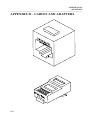
APPENDIX E.................................................................................... 213
xi
M SERIES DAC
TABLE OF CONTENTS
____________________________________________________________________________
INDEX ............................................................................................... 215
xii
M SERIES DAC
INTRODUCTION TO THE M SERIES DAC
____________________________________________________________________________
INTRODUCTION TO THE M SERIES DAC
The BayTech M Series Data Acquisition and Control (DAC) models are versatile
multifunction units used in data collection and process control. Typical applications
include security alarm monitoring, HVAC systems, medical data systems control,
manufacturing, and environmental data control. An M Series system consists of a
base unit, host communication module(s), and various I/O modules.
The base unit is comprised of 3, 4, 6, 9, or 16 card slots, activity LEDs, service port,
time-of-day clock (optional), power supply, and an internal high speed data bus. The
service port and optional service modem allow menu-driven configuration of the main
unit and installed modules from a local or remote terminal.
The host communication modules are the primary user interface to the M-Series DAC
system. These modules allow the user to connect to the main unit or I/O modules and
change configuration, send and receive data, and issue data commands. The host
modules include:
Introduction
Configuration
page 2
page 2
page 2
page 47
page 51
page 98
(V71) Host Module
(V72TP) Host Module
(V93A) Host Module
Operation
page 107
page 109
page 177
IMPORTANT: The first module slot of any unit equipped with LCD and
front panel controls must be occupied by a host module.
The I/O modules are used to interface directly to various peripheral devices such as
security/alarm systems, process control systems, medical data systems, and
environmental control systems. The I/O module types include:
Introduction
(V74)
(V75)
(V87)
(V77)
(V78)
1
A 4 EIA-232 serial
I/O port module
A 4 EIA-232/422
I/O port module
A 4 EIA-485/422
I/O port module
An 8 or 16 channel
12 bit A/D
convertor
An 8 channel
control relay
Configuration
Operation
page 3
page 57
page 132
page 3
page 57
page 132
page 3
page 57
page 132
page 3
page 64
page 142
page 4
page 80
page 150
M SERIES DAC
INTRODUCTION TO THE M SERIES DAC
____________________________________________________________________________
(V79/V80)A 16 channel
switch or optically
isolated inputs
(V82) A Programmable
Control module
(M03) A 16 MB memory
module
page 5
page 90
page 157
page 5
-----
page 166
page 5
-----
-----
THE V71 Host Communication Module is a user interface to the BayTech M Series
Data Acquisition and Control (DAC) units. This module allows a connected host
terminal to issue specific configuration or data commands to the various I/O modules
or the M Series unit main board. Multiple V71 modules can be installed in an M
Series chassis allowing certain I/O module types to send data to specific V71
modules. The V71 module allows for multiple line interface types including EIA-232,
EIA-422, and current loop and supports serial speeds up to 115.2K bps. Other
programmable features in addition to the serial interface and baud rate include word
size, stop bits, parity, XON/XOFF handshaking, and the port select code. In addition,
the V71 module allows for RJ-45 or DB-25 cabling.
THE V72TP host communications modules are a user interface for use with the
BayTech M-Series Data Acquisition and Control (DAC) units. The V72TP allows
network users, operating on a device using a TCP/IP stack with an Ethernet connection,
to access various DAC peripheral modules. The V72TP host communications module
has an Ethernet interface which provides access and control of M-Series DAC
peripheral modules via TELNET session or through user software using a direct socket
connection.
The V72TP is capable of concurrently supporting one connection per installed port. For
example, an M16 with a V72TP and fifteen V74 4-port serial I/O modules can be
operated with a separate connection to each port for a total of 60 simultaneous sessions.
The V72TP supports Ethernet II and Ethernet SNAP frame types automatically,
eliminating concern about DLC compatibility.
V93A The V93A Host Communication Modem Module is the remote user interface
to the BayTech M Series DAC units. This module features a V.32bis/V.42bis internal
modem and allows a remote host terminal to connect and issue specific configuration
or data commands to the various I/O modules or the M Series DAC unit main board.
Multiple V93A modules can be installed in a M Series chassis allowing I/O modules
to send data to specific V93A modules.
IMPORTANT: You should determine what types of peripheral modules you
have installed in your M-Series DAC unit in addition to the host module. You
should familiarize yourself with the various operation modes of the installed
peripheral modules.
2
M SERIES DAC
INTRODUCTION TO THE M SERIES DAC
____________________________________________________________________________
THE V74, V75, and V87 I/O modules are installed in a BayTech M Series DAC and
are used in conjunction with a host module. The V74 has four EIA-232 serial ports,
the V75 has four selectable EIA-232/EIA-422 serial ports, and the V87 has four
selectable EIA-422/EIA-485 serial ports.
These modules allow a host computer system connected to the host module to
individually select up to four peripheral devices (e.g., bar code readers, security
systems, digital instruments, etc.) and send data to, or receive data from the selected
device. The V74/V75/V87 modules will simultaneously multiplex incoming data
from the peripheral devices to be transmitted to the host system. The method of data
transmission from the peripheral devices to the host system is dependent upon the
mode of operation. Each 4-port serial module features three user-selectable modes of
operation. The three modes of operation are:
Full Duplex Communication - Allows the host module to switch between
four peripheral devices and provides bidirectional data transfer between the host
module and the selected peripheral device. Data received from non-selected
peripheral devices is stored in a buffer until the port is selected by the host system.
Immediate Reporting Method - Provides automatic message multiplexing
from all peripheral devices. Data is buffered until a terminating character is received
or 256 characters are received. Messages are then sent to the host computer preceded
by a port identification code.
Command Reporting Method - Reports a single message, all messages, or
all buffered data from specific peripheral devices upon request from the host
computer. The V74/V75/V87 may be placed into "broadcast" mode where any data
received by a host module will be sent out all four ports of the selected module(s)
simultaneously.
In addition to the modes of operation, you may select the serial port configuration and
logical name for each port, the designated host module location, and the message
terminate character. These parameters are programmed by entering configuration
mode from the host module or service port. Changes are saved permanently in nonvolatile memory.
THE V77 ADM-1 programmable analog-to-digital input board, is a plug-in module
designed for use with the BayTech M Series DAC Data Acquisition Controllers. The
primary feature of the ADM-1 is a 12 bit, successive approximation, analog-to-digital
converter which provides conversion of data with high accuracy and resolution at
moderate throughput rates.
The ADM-1 can be operated as either eight differential or 16 single-ended inputs.
Signal input connections to the ADM-1 are made through a standard DB-25 female
connector. Data resolution is 12 bits using unipolar (0 to +X volts) operation or 11
bits plus sign in the bipolar (-X to +X volts) mode. A total of eight software
selectable and one hardware (jumper) selectable, unipolar/bipolar input voltage ranges
3
M SERIES DAC
INTRODUCTION TO THE M SERIES DAC
____________________________________________________________________________
are available. Three point (25%, 50% 75%) self-calibration is provided in software to
reduce or remove errors introduced by input offsets.
Sample rates up to 4000 S/sec and data averaging from 1 to 4000 samples are
selectable through configuration options. Data averaging can be expanded to include
larger sample sets through the use of BayTech, or commercially available, application
software. Time stamping or "Time Tagging" of data is available through the use of a
"time-of-day" clock located in the base unit. A time tag includes month, day, year,
hour, minute and second.
Data samples are supplied to the host computer/controller from any of the following
modes:
1.
2.
3.
Upon user request (COMMAND).
At a specific date and/or time (SCHEDULE).
Real time sampling (i.e., as samples are received or IMMEDIATE).
THE V78 CRM-1 eight channel, control relay module is a microprocessor controlled
plug-in unit designed for use with the BayTech M16 Data Acquisition Controllers.
The main feature of the CRM-1 is eight (8) fully programmable, electromechanical,
form-C, single-pole-double-throw (SPDT) relays. Each relay has a set of normally
open (NO) and a set of normally closed (NC) contacts.
All relays on the V78 CRM-1 are programmable to change state by sending data
commands or via time schedule by a host computer/controller. The status of a relay
(energized or de-energized) may be requested by a host computer/controller. The
relay status may consist of buffered data representing the history of changes in the
state of a specific relay or the current state of a specific relay. The relay status may
be provided with a "time stamp or "Time Tag" which is available through the use of a
"time-of-day" clock located in the base unit. A time tag includes the month, day,
year, hour, minute and second the relay status was taken.
Relay status data is supplied to the host computer/controller in one of the following
modes:
1)
2)
3)
Upon user request (COMMAND).
At a specific date and time (SCHEDULE).
Real time reporting of events (IMMEDIATE).
NOTE: An event is the change-in-state of a relay (i.e., energized to deenergized or vice versa).
Signal input connections to the CRM-1 are made through a standard DB-25F (25 pin
female) connector.
4
M SERIES DAC
INTRODUCTION TO THE M SERIES DAC
____________________________________________________________________________
THE V79/V80 PDI modules are designed for use with the M16 (DAC) Data
Acquisition Controller. Both modules are used to detect events where an event is
defined as a change-in-state of an input and return to the original state. The V79 PDI1 module is used for the detection of switch closure in applications requiring
notification of device status such as burglar alarms, fire alarms, event counters and
timers, process control, etc.. The V80 PDI-2 is used for the detection of optically
isolated voltage inputs in applications requiring industrial control of motors, process
monitoring, limit switch status, and the monitoring of relay status.
All events detected by either module are recorded as an event sample and sent to a
host computer/controller connected to a host module. The current status of input
channels may be provided to the host computer/controller upon request. Event
samples or input channel status may be provided with a "time stamp" or "Time Tag"
which is available through the use of a "time-of-day" clock located in the base unit. A
time tag includes the month, day, year, hour, minute and second the event occurred or
the input channel status was taken.
Event status is supplied to the host computer/controller in one of the following
modes:
1)
2)
3)
Upon user request (COMMAND).
At a specific date/time (SCHEDULE).
Real time reporting of events (i.e., as events occur IMMEDIATE).
THE V82 Programmable Control Module (PCM-1) is used to monitor, control, and
report information about devices connected to the M-Series peripheral modules. The
M-Series peripheral modules are used to interface directly to various devices such as
security/alarm systems, process control systems, medical data systems, and
environmental control systems.
Bay Tech provides C library functions specific to the various peripheral modules.
These functions allow you to write C programs to perform data acquisition and
control applications such as process control, remote control and monitoring and data
gathering.
Programming the V82 PCM-1 is accomplished by writing a C-based source program,
compiling and linking this program for use on the 64180 microprocessor, and
downloading the corresponding HEX file to the flash EPROM. The C library
functions provided are specific for the 2500AD software, Inc. 64180 C compiler.
THE M03 memory module can hold from 1MB to 16MB total buffer size. It is used to
expand the memory capabilities of the various module buffers.
5
M SERIES DAC
QUICK START
____________________________________________________________________________
QUICK START
6
M SERIES DAC
CABLING
____________________________________________________________________________
CABLING
BASE UNIT CABLING
SERVICE PORT/SERVICE MODEM CABLING
If you have a unit equipped with a service modem, the cable required to connect the
telephone interface to the modem port is a standard 4-pin modular straight-through
cable.
CAUTION: Use caution when installing or modifying telephone lines.
Never install telephone wiring during a lightning storm. Never install
telephone jacks in wet locations unless the jack is specifically designed for
wet locations. Never touch uninsulated telephone wires or terminals unless
the telephone line has been disconnected at the network interface.
The service port has an RJ-45 modular connector. Most serial computers and
terminals do not have modular connectors. Therefore, adapters are required to
convert from DB-25 or DE-9 connectors to modular connectors. The service port
uses the following communication signals:
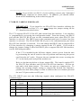
SERVICE PORT 8-PIN MODULAR EIA-232 PIN/SIGNAL DEFINITION
PIN
SIGNAL
DIRECTION
DESCRIPTION
1
DTR
Output
Data Terminal Ready. Enable/disable receiving characters
2
GND
--------
Signal Ground
3
RTS
Output
Request To Send. +12 Volts when unit is powered on.
4
TX
Output
Transmit Data
5
RX
Input
Receive Data
6
DSR
Input
Data Set Ready. Not used as a handshake line.
7
DCD
Output
Data Carrier Detect. +12 Volts when unit is powered on.
8
CTS
Input
Clear To Send. Enable/disable transmitting characters
An adapter is required to connect an IBM PC to the service port. The 9FRJ45PC-3
and 25FRJ45PC-3 adapters are used for this connection. The pinout for these
adapters is displayed in Appendix D.
7
M SERIES DAC
CABLING
____________________________________________________________________________
V71 CABLING
The V71 has a DB-25 and two RJ-45 connectors for interface to the host terminal.
The V71 supports three line interfaces: EIA-232, EIA-422, and current loop. The
factory default setting provides EIA-232 line interface on the DB-25 port and the
EIA-232 RJ-45 port. The line interface is programmed by entering the V71
configuration mode (see page 47).
If you change the line interface to EIA-422 in configuration mode, the default
hardware settings provide EIA-422 line interface on the EIA-422/485 RJ-45 port.
You can change a hardware jumper setting on the module that provides EIA-422 line
interface on the DB-25 port. This procedure is discussed on page ???
Current loop line interface is provided on the DB-25 port only.
IMPORTANT: Before you proceed with cabling your equipment to the
V71, you should determine the required line interface for your application
and verify the connector type and pin/signal definitions for your equipment.
V71 DB-25 CABLING FOR EIA-232
The DB-25 port on the V71 has a male DTE type connector and uses the following
pins and signals for communication:
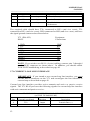
DB-25 PIN/SIGNAL DEFINITION FOR EIA-232 LINE INFORMATION
8
Pin
#
EIA232
Signal
Direction
1
PGND
----
2
TX
Output
3
RX
Input
4
RTS
Output
5
CTS
Input
7
SGND
----
20
DTR
Output
Description
Protective Ground
Transmit Data (data out)
Receive Data (data in)
+ 12 volts when the M16/M8 DAC is powered up.
Handshake In, enable/disable the transmission of
characters
Signal Ground
Handshake Out, enable/disable the receiving of
characters
M SERIES DAC
CABLING
____________________________________________________________________________
If you are interfacing a DCE device such as a modem to the V71 DB-25 port, you
must use a straight cable as shown in Appendix D. If you are interfacing a DTE
device such as a terminal to the V71 DB-25 port, you must use a crossed or null
modem cable as shown in Appendix D.
V71 RJ-45 CABLING FOR EIA-232
The V71 provides EIA-232 line interface on the EIA-232 RJ-45 modular port. Most
serial computers, modems, and printers do not have RJ-45 modular connectors.
Adapters are required to convert from DB-25 or DE-9 connectors to modular
connectors. BayTech has a complete line of RJ-45 adapters and cables that make
your installation quick and trouble free. There are drawings, in Appendix D, of an RJ45 receptacle and plug where pin number assignments are given.
The V71 EIA-232 modular port uses the following signals:
EIA-232 RJ-45 PIN/SIGNAL DEFINITION
Direction
Description
P
i
n
EIA-232
Signal
1
DTR
Output
2
GND
----
3
RTS
Output
4
5
TX
RX
Output
Input
6
N/A
----
Not Used
7
GND
----
Signal Ground
8
CTS
Input
Handshake Out, enable/disable the receiving of characters
Signal Ground
+12V when powered is applied, not used as a handshake
line
Transmit Data (data out)
Receive Data (data in)
Handshake
characters
In,
enable/disable
the
transmission
of
COMPUTER INTERFACE, MODEM INTERFACE
An adapter is required to connect an IBM PC to the V71 serial port. The 9FRJ45PC1 and 25FRJ45PC-1 adapters are used for this connection. The 25MRJ45MD-1
adapter is used to connect to an external modem. The pinout for these adapters is
displayed in Appendix D.
IMPORTANT: When modular connectors are used, crossed RJ-45 cables
are required.
9
M SERIES DAC
CABLING
____________________________________________________________________________
V71 EIA-422 LINE INTERFACE
NOTE: When using EIA-422 line interface, you must access configuration
mode and reconfigure the line interface to EIA-422.
V71 RJ-45 CABLING FOR EIA-422
The V71 RJ-45 port uses the following signals for EIA-422 communication:
Pin
RJ-45 PIN/SIGNAL DEFINITION FOR EIA-422 LINE INTERFACE
EIA-422
Direction
Description
Signal
1
HSO
Output
2
GND
----
Handshake Out, enable/disable the receiving of
characters
Signal Ground
3
4
TX+
TX-
Output
Output
Transmit Data (+)
Transmit Data (-)
5
6
RXRX+
Input
Input
Receive Data (-)
Receive Data (+)
7
8
GND
HSI
---Input
Signal Ground
Handshake In, enable/disable the transmission of
characters
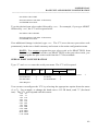
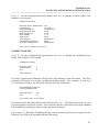
You can use either RJ-45 (8-wire) or RJ-11 (4-wire) cabling when connecting the host
computer or terminal to the V71 using EIA-422 line interface. The required cable
should have TX+ connected to RX+ (and vice versa), TX- connected to RX- (and vice
versa), HSO connected to HSI (and vice versa), and have the signal grounds
connected.
V71 (EIA-422, 8-wire)
RJ-45
1
2
3
4
5
6
7
8
HSO
GND
TX+
TXRXRX+
GND
HIS
Equipment
Connections
HSI
GND
RX+
RXTXTX+
GND
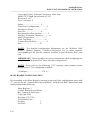
HSO
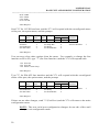
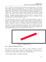
V71 RJ-45 (8-wire) Connection for EIA-422 Line Interface
10
M SERIES DAC
CABLING
____________________________________________________________________________
NOTE: If you wish to use RJ-11 (4-wire) cabling, connect pins 3 through 6
on the RJ-45 connector as shown above. In addition, you should enable
XON/XOFF handshaking as described on page 49.
V71 DB-25 CABLING FOR EIA-422
IMPORTANT: If you intend to use EIA-422 line interface utilizing the
DB-25 connector on the V71, you must change the jumper setting on the
V71 board as described below.
The V71 supports EIA-232, EIA-422, and current loop line interface. Line interface
is programmed by accessing the configuration mode. From the factory, the DB-25
port and the EIA-232 RJ-45 port are the communication ports when EIA-232 line
interface is selected. The DB-25 port is the communication port if current loop line
interface is selected. The EIA-422/485 RJ-45 port is the communication port when
EIA-422 line interface is selected. You can change the DB-25 port to support EIA422 line interface by changing a jumper setting on the V71 board. If you wish to
change the jumper setting to allow the DB-25 port to support EIA-422 line interface,
use the following procedure:
If the V71 is installed in the M Series chassis, remove power from the unit
by positioning the on/off switch to the off position and removing the power
cord from the AC outlet. Unscrew the two straight slot screws securing the
V71 to the back panel and pull the module out.
Refer to the drawing below to locate jumper JP4. The board is marked 232
for EIA-232 line interface and 422 for EIA-422 line interface. JP4 has six
pins and a dual shunt jumper. The center two pins are common pins. To
change the existing jumper setting to support the desired line interface,
position the dual shunt jumper so that it connects the two common pins and
the two 232 pins or the two 422 pins.
The V71 DB-25 port uses the following signals when configured for EIA-422
communication:
Pin
#
1
2
3
5
DB-25 PIN/SIGNAL DEFINITION FOR EIA-422 LINE INTERFACE
EIA-422
Direction
Description
Signal
PGND
---Protective Ground
TXOutput
Transmit Data (-)
RXInput
Receive Data (-)
HSI
Input
Handshake In, enable/disable the
transmission of characters
11
M SERIES DAC
CABLING
____________________________________________________________________________
7
SGND
----
Signal Ground
14
TX+
Output
Transmit Data (+)
16
RX+
Input
Receive Data (+)
20
HSO
Output
Handshake Out, enable/disable the receiving
of characters
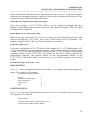
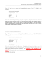
The required cable should have TX+ connected to RX+ (and vice versa), TXconnected to RX- (and vice versa), HSO connected to HSI (and vice versa), and have
the signal grounds connected as shown below.
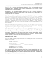
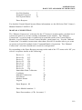
V71 (EIA-422)
DB-25
Equipment
Connections
1 GND
2 TX3 RX5 HSI
7 GND
14 TX+
16 RX+
20 HSO
GND
RXTXHSO
GND
RX+
TX+
HSI
NOTE: If you wish to use RJ-11 (4-wire) cabling, connect pins 3 through 6
on the RJ-45 connector as shown above. In addition, you should enable
XON/XOFF handshaking as described on page 49.
V71 CURRENT LOOP LINE INTERFACE
IMPORTANT: If you intend to use current loop line interface, you must
use the DB-25 connector on the V71 and reconfigure the line interface to
current loop as described on page 49
Current loop line interface provides active transmit and active or passive receive
signals. The V71 RJ-45 port uses the following signals for current loop line interface
with active transmit and passive receive:
DB-25 PIN/SIGNAL DEFINITION FOR CURRENT LOOP
(ACTIVE TX PASSIVE RX)
Pin#
Current Loop Signal
Direction
Description
9
TX+
Output
Transmit Data (+)
12
M SERIES DAC
CABLING
____________________________________________________________________________
11
TX-
Output
Transmit Data (-)
18
RX+
Input
Receive Data (+)
25
RX-
Input
Receive Data (-)
The V71 RJ-45 port uses the following signals for current loop line interface with
active transmit and active receive:
DB-25 PIN/SIGNAL DEFINITION FOR CURRENT LOOP (ACTIVE TX ACTIVE RX)
Pin#
Current Loop Signal
Direction
Description
7
GND
----
Ground
9
TX+
Output
Transmit Data (+)
11
TX-
Output
Transmit Data (-)
18
RX-
Input
Receive Data (-)
19
RX+
Input
Receive Data (+)
25
GND
----
Ground
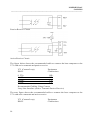
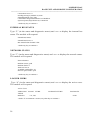
The figures below show the basic active transmit circuit, the basic passive receive
circuit, and the basic active receive circuit.
Basic Active Transmit Circuit
13
M SERIES DAC
CABLING
____________________________________________________________________________
Passive Receive Circuit
Active Receive Circuit
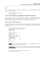
The figure below shows the recommended cable to connect the host computer to the
V71 with active transmit and passive receive.
V71 (Current Loop)
DB-25
9 TX+
11 TX18 RX+
25 RX-
Equipment
Connections
RX+
RXTX+
TX-
Recommended Cabling Using Current
Loop Line Interface (Active Transmit Passive Receive)
The next figure shows the recommended cable to connect the host computer to the
V71 with active transmit and active receive.
V71 (Current Loop)
DB-25
14
Equipment
Connections
M SERIES DAC
CABLING
____________________________________________________________________________
9 TX+
11 TX18 RX19 RX+
7
25
RX+
RXTXTX+
GND
GND
Recommended Cabling Using Current
Loop Line Interface (Active Transmit Active Receive)
NOTE: The preceding figures show the transmit and receive
connections in pairs. Each pair should be connected with twistedpair cabling.
V72TP
10BASE-T (MODULAR) CONNECTION
If your network uses 10BASE-T RJ-45 connectors, connect an RJ-45 cable between the
RJ-45 port and the network hub. The modular port is defined as DTE (i.e., Pin 1 is
TD+, Pin 2 is TD-, Pin 3 is RD+, and Pin 6 is RD-). Most RJ-45 network hubs will
require a straight cable type. The LINK (link integrity) LED on the back panel and at
the connected port on the hub will illuminate if there is a good connection between the
V72/V72TP and the hub.
V74/V75/V87 CABLING
Ports on the V74 & V75 modules use the following pins and signals for
communication:
V74 & V75 PINOUT INFORMATION
PIN
1
SERIAL INTERFACE
RS-232
V74/75
RS-422
V75
DTR
HSO or
+12V
DIRECTION
Output
DESCRIPTION
232 - Data
Terminal Ready
422 - Handshake
Out or +12V
Used to enable or
disable the
receiving of
characters
15
M SERIES DAC
CABLING
____________________________________________________________________________
2
GND/
DCD
OUT
GND
--- / Output
Signal Ground(Default) or User
selectable DCD "OUT"
3
RTS
TX+
Output
232 - +12V Out
422 - Transmit Data (+)
4
TX
TX-
Output
232 - Transmit Data
422 - Transmit Data (-)
5
RX
RX-
Input
232 - Receive Data
422 - Receive Data (-)
6
DSR
RX+
--- / Input
232 - Handshake In
422 - Receive Data (+)
GND
--- / Input
Signal Ground(Default) or User
selectable DCD "IN"
HSI
Input
232 - Clear To
Send
422 - Handshake
In
7
8
GND/
DCD IN
CTS
Used to enable
or disable the
transmitting of
characters
IMPORTANT: Before you proceed with cabling your equipment to this
module, you should verify the connector type and the pin/signal definitions
for your equipment.
Ports on the V74, V75, and V87 modules have 8-pin modular connectors. Most serial
computers, modems, and printers do not have modular connectors. Therefore,
adapters are required to convert from either DB-25 or DE-9 connectors to modular
connectors. BayTech has a complete line of modular adapters and cables that makes
your installation quick and trouble free.
CAUTION: Do not use 4-wire modular cabling with the V74 & V 75
modules.
V74 & V75 DCD STATUS SELECTION
Each EIA-232 port can be configured so DCD can be an input or output signal by
positioning jumpers on the main board of the module for each individual port. See
V74 & V75 Jumper selection layout(Figures 29 & 30 or V75 Mechanical Layout
Section D.2).
A. GROUND---Pins 2 & 7 of each port are signal ground in the default setting. This
default setting is used in most data acquisition and control applications. Locate the
16
M SERIES DAC
CABLING
____________________________________________________________________________
eight jumper locations for DCD status selection. Jumpers (JP5,JP7,JP9, & JP11) are
used to configure DCD as an output for pin 2 for each port of the module. Jumpers
(JP6,JP8,JP10, & JP12) are used to configure DCD as an input for pin 7 for each port
of the module. Each port is configured from the factory with pins 2 and 7 as ground.
1. V75 (See Figure 29)--- Each port's jumper position for "ground" connects
the center pin and the pin located closest to the RJ-45 connector.
2. V74 (See Figure 30)--- Each port's jumper position for"ground" connects
the center pin and the pin located on the right with the RJ-45 connectors facing you.
In both V74 and V75 applications use BayTech adapter, part number 25FRJ45PC-1
or 9FRJ45PC-1.
B. DCD "IN"---The DCD "IN" jumper selection is selected in applications where the
individual port of the V74 or V75 will be communicating with a modem. To change
the EIA-232 pin/signal definition for a V74 or V75 port to have pin 7 configured for
DCD "IN" you must change the location JP6 for port 4, JP8 for port 3, JP10 for port
2, or JP12 for port 1.
1. V75 (See Figure 29)---Install the two position jumper so that it connects
the center pin and the pin farthest away from the RJ-45 port. Do not move the other
jumpers.
2. V74 (See Figure 30)---Install the two position jumper so that it connects
the center pin and the pin located on the left of the common pin with the RJ-45 port
facing you. Do not move the other jumpers. In these two applications use BayTech
adapter, part number 25FRJ45MD-4.
C. DCD "OUT"---The DCD "OUT" jumper selection is used in applications where
an individual port of the V75 will look like a modem connection if a computer or
terminal is connected to the port. Some terminals and popular communications
software packages require that DCD is "high" for a connection to be completed. To
change the EIA-232 pin/signal definition for a V74 or V75 port to have pin 2
configured for DCD "OUT" you must change the location of JP5 for port 4, JP7 for
port 3, JP9 for port 2, or JP11 for port 1.
1. V75 (See Figure 29)---Install the two position jumper so that it connects
the center pin and the pin farthest away from the RJ-45 port. Do not move the other
jumpers.
2. V74 (See Figure 30)---Install the two position jumper so that it connects
the center pin and the center pin and the pin located on the left of the common pin
with the RJ-45 connectors facing you. Do not move the other jumpers. In this
application use BayTech adapter, part number 25FRJ45PC-3 or 9FRJ45PC-3.
IMPORTANT: If the module is installed in the base unit chassis, remove
power from the unit by positioning the On/Off switch to "0" (off) and
unplugging the power cord from the AC outlet. Remove the module by
17
M SERIES DAC
CABLING
____________________________________________________________________________
unscrewing the two screws securing it to the back panel and pulling the
module out.
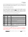
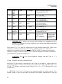
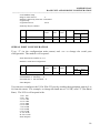
14.1.2 DCD STATUS SELECTION CHART--EIA-232 MODE ONLY (see the
charts below for jumper settings)
A. DCD "GROUND" is the default setting where DCD is not used by either end of
the connection(modems are not used). See figures 29 & 30 for jumper locations.
PORT #
JP POSITIONS
PORT #1
11 GROUND
12 GROUND
PORT #2
9 GROUND
10 GROUND
PORT #3
7 GROUND
8 GROUND
PORT #4
5 GROUND
6 GROUND
USE ADAPTER: 25FRJ45PC-1 OR 9FRJ45PC-1
B. DCD "OUT" or high for computers or terminals connected to the V74 or V75 that
will to be communicating with a modem. See figures 29 & 30 for jumper locations.
PORT #
JP POSITIONS
PORT #1
11 OUT
12 GROUND
PORT #2
9 OUT
10 GROUND
PORT #3
7 OUT
8 GROUND
PORT #4
5 OUT
6 GROUND
USE ADAPTER: 25FRJ45PC-3 OR 9FRJ45PC-3
18
M SERIES DAC
CABLING
____________________________________________________________________________
C. DCD "IN" or low which is necessary when a V74 or V75 port is connected to a
modem. See figures 29 & 30 for jumper location.
PORT #
JP POSITIONS
PORT #1
11 GROUND
12 IN
PORT #2
9 GROUND
10 IN
PORT #3
7 GROUND
8 IN
PORT #4
5 GROUND
6 IN
USE ADAPTER: 25FRJ45MD-4
Refer to the line drawings below for DCD "IN", DCD "OUT" or "GROUND"
selections and also for EIA-422 or EIA-232 selection.
V75 JUMPERS are given on the drawing below. The RJ-45 connectors face toward
the bottom of the page.
Insert v75 jumper drawing
V74 JUMPERS are given on the drawing below. The RJ-45 connectors face toward
the bottom of the page.
Insert v74 jumper drawing
14.1.3
V75 SERIAL INTERFACE SELECTION
The desired V75 serial interface is selected by positioning jumpers on the main board
of the module for each individual port. The factory default serial interface is EIA422.
19
M SERIES DAC
CABLING
____________________________________________________________________________
Refer to Figure 29 on previous page and locate the eight jumper locations for serial
interface selection. These jumper locations are marked on the mechanical layout as
JP13 and JP14 for Port 1, JP15 and JP16 for port 2, JP17 and JP18 for Port 3 and
JP19 and JP20 for Port 4.
Each port is configurable for EIA-422 or EIA-232 serial interface by installing two, 4
position jumpers to either the 422 or 232 position as marked on the board. The center
row of pins for each port will be occupied by four of the jumper positions and the row
of pins for either 422 or 232 will be occupied by the other four positions of these two
jumpers.
IMPORTANT: If the V75 module is installed in the base unit chassis,
remove power from the unit by positioning the On/Off switch to "O" (off)
and unplug the power cord from the AC outlet. Remove the module by
unscrewing the two screws securing it to the back panel and pull the module
out.
14.1.4
V74 AND V75 CABLE/ADAPTER INFORMATION
Refer to the following modular adapter drawings to interface your computers or
terminals to the V74 and the V75 module using EIA-232 serial interface. Use the
"...PC-1" adapters in most data acquisition and control applications where the V74 or
V75 will not have modem connections.
Refer to Figure 31 if your
computers/terminals have DB-25 male connectors or to Figure 32 if your
computers/terminals have DE-9 connectors.
Insert drawings for the 25 pin and 9 pin pc1 adapter
Refer to the following modular adapter drawings to interface your computers or
terminals to the V74 or V75 module using EIA-232 serial interface. Use the "...PC3" adapters in applications where a port of the V75 will look like a modem connection
when a computer or terminal is connected to the port. Some terminals and popular
communications software packages require that DCD is "high" for a connection to be
completed. Refer to Figure 33 if your computers/terminals have DB-25 male
connectors or to Figure 34 if your computers/terminals have DE-9 connectors.
Insert drawings of the 25 and 9 pin PC3 adapters
20
M SERIES DAC
CABLING
____________________________________________________________________________
Refer to the following modular adapter drawing (Figure 35) to interface modems to
the V74 or V75 module.
Insert the 25 pin
md4 adapter
Refer to the modular adapter drawing (Figure 36) below to connect an EIA-232 serial
printer to the V74 or V75 module.
Insert the 25 pin pr2 adapter
IMPORTANT: When BayTech modular adapters are used as given in
Figures 31-36, a crossed 8-wire modular cable is required. Do not use 4wire modular cabling.
Insert the crossed cable drawing
14.1.5
V75 EIA-422 CABLING
The cable required to connect an EIA-422 device to the V75 module using EIA-422
serial interface must have TX+ wired to RX+ (and vice versa), TX- wired to RX- (and
vice versa), HSO wired to HSI (and vice versa), and the grounds connected. Please
see Figure 37.
V75 (EIA-422)
RJ-45
1
2
3
4
5
6
7
8
HSO
GND
TX+
TXRXRX+
GND
HSI
Equipment
Connections
HSI
GND
RX+
RXTXTX+
GND
HSO
Figure 37: V75 EIA-422 Connection
21
M SERIES DAC
CABLING
____________________________________________________________________________
NOTE: The HSO, HSI, and GND signals do not need to be connected if you
are not using hardware handshake lines.
14.3
V87 CABLING INFORMATION
The V87 module has four ports that are user selectable as EIA-422 or EIA-485 serial
interface. Ports on the V87 module use the following pins and signals for
communication:
V87 PINOUT INFORMATION
PIN
SERIAL INTERFACE
DIRECTION
DESCRIPTION
EIA-422
EIA-485
1
HSO
HSO
Output
Handshake Out. Used to enable or disable
the receiving of characters
2
GND
GND
----
Signal Ground
3
TX+
TX+/RX+
Output
Output/Input
422 - Transmit Data (+)
485 - Transmit/Receive Data (+)
4
TX-
TX-/RX-
Output
Output/Input
422 - Transmit Data (-)
485 - Transmit/Receive Data (-)
5
RX-
NU
Input/----
232 - Receive Data (-)
485 - Not Used
6
RX+
NU
Input/----
422 - Receive Data (+)
485 - Not Used
22
M SERIES DAC
CABLING
____________________________________________________________________________
7
GND
8
HSI
14.3.1
V87 SERIAL INTERFACE SELECTION
HSI
----
Signal Ground
Input
Handshake In. Used to enable or disable the
transmitting of characters
The desired serial interface is selected by positioning jumpers on the main board of
the module for each individual port. Please refer to Section 14.2.3 (V75 EIA-422
Cabling) for cabling information if using EIA-422 serial interface (default). If you
wish to change one or more of the ports to operate using a different serial interface,
please use the following procedure:
a.
IMPORTANT: If the V87 module is installed in the base unit chassis,
remove power from the unit by positioning the On/Off switch to "0" (off)
and unplugging the power cord from the AC outlet. Remove the module by
unscrewing the two straight slot screws securing it to the back panel and
pulling the module out.
b.
Refer to Figure 39 on the following page and locate the four six-position
jumper locations for serial interface selection. The jumper locations are
marked on the assembly drawing for serial interface selection as JP5 for Port
1, JP8 for Port 2, JP11 for Port 3, and JP14 for Port 4.
c.
Each port is configurable for EIA-422 or EIA-485 serial interface by
installing a four-position jumper to either the 422 or 485 position as marked
on the board. The center row of pins for each port are occupied by two of
the jumper positions and the row of pins for either 422 or 485 are occupied
by the other two positions of this jumper.
NOTE: A termination resistor is installed by default. You can remove the
termination resistor for each individual port by moving JP4, JP7, JP1, or
JP13 away from the R/T position for Ports 1, 2, 3, or 4 respectively.
d.
Install the V87 module into the base unit chassis (see Section 4.5).
Insert the v87 mechanical drawing
14.3.2
V87 EIA-485 CABLING
23
M SERIES DAC
CABLING
____________________________________________________________________________
The cable required to connect an EIA-485 device to the V87 module using EIA-485
serial interface must have TX+/RX+ wired to the TX+/RX+ line of your equipment,
TX-/RX- wired to TX-/RX-, HSO wired to HSI (and vice versa), and the grounds
connected. Please see Figure 40.
V87 (EIA-485)
RJ-45
1
2
3
4
7
8
HSO
GND
TX+/RX+
TX-/RXGND
HIS
Equipment
Connections
HSI
GND
TX+/RX+
TX-/RXGND
HSO
Figure 40: V87 EIA-422 Connection
NOTE: The HSO, HSI, and GND signals do not need to be connected if you
are not using hardware handshake lines.
RJ-45 CABLES AND ADAPTERS
IMPORTANT: All RPC models have an RJ-45 port for connecting to a
local EIA-232 device such as a computer terminal or external modem. Most
serial computers do not have RJ-45 connections; therefore, an adapter is
provided with this unit to convert from a DE-9 connector to an RJ-45
connector (BayTech Part No. 9FRJ45PC-1). An adapter to convert from a
DB-25 connector to an RJ-45 connector is also available from BayTech,
upon request (BayTech Part No. 25FRJ45PC-1).
24
M SERIES DAC
CABLING
____________________________________________________________________________
Figure 1: RJ-45 receptacle
Figure 2: RJ-45 plug
The RPC RJ-45 control port uses the following signals:
EIA-232 RJ-45 PIN/SIGNAL DEFINITION
Pin
EIA-232
Signal
Direction
Description
1
DTR
Output
+10V when activated by DCD. Toggles on logout for modem
disconnect.
2
GND
----
Signal Ground
3
RTS
Output
+10V when powered is applied, not used as a handshake line
4
TX
Output
Transmit Data (data out)
5
RX
Input
Receive Data (data in)
6
N/C
N/C
No Connection
7
GND
-------
Signal Ground
8
DCD
Input
DCD into the RPC/Not used on RPC-2 MD01
Modem Communications: A modem can be connected to the EIA-232 serial port by
using a 25MRJ45MD-8 adapter (Figure 6). Several types of modem adapters are
available from BayTech. Contact an applications engineer for help in choosing the
correct adapter.
25
M SERIES DAC
CABLING
____________________________________________________________________________
RJ-45
1
BLUE
2
ORANGE
3
BLACK
4
RED
5
6
1
DCD
2
RX
3
TX
4
DTR
5
GND
6
DSR
7
RTS
8
CTS
FEMALE DE-9
GREEN
YELLOW
7
BROWN
8
GRAY
Figure 5: Computer/Terminal Adapter
BayTech Part No. 9FRJ45PC-1
Crossed RJ-45 cable is required
Figure 7: Crossed 8-pin Modular Cable
BayTech Part No. RJ08X007 (7 feet)
IMPORTANT: Crossed RJ-45 cables are required when modular connectors
are used, as shown in Figures 4 – 6, or to interface the RPC to another BayTech
product with modular connectors, such as the DS-Series data switch.
26
M SERIES DAC
CABLING
____________________________________________________________________________
V77 Pinout
The V77 ADM-1 is installed in the M Series chassis as described in the installation
section of this manual.
NOTE: The V77 ADM-1 cannot be installed as Module 1. If a V77 ADM-1
is removed from a module slot and a different V77 ADM-1 is installed in
that location, the newly installed module acquires the previous module's
configuration. Moving a V77 ADM-1 to a different module location
requires reconfiguration because the configuration parameters are stored as a
function of slot location and module type. The configuration information
does not stay with a relocated module.
IMPORTANT: You must install jumper JP1 to use +10V range. First,
remove the ADM-1 from the M Series chassis. Next, locate JP1 in Appendix
B and install a jumper connector on JP1.
Once the ADM-1 has been installed in the M Series chassis, connect a cable with a
DB-25 male connector to the input connector, J2. Determine if you will be using
single-ended or differential inputs. Singled-ended operation allows up to 16 inputs
using grounds of the same potential. Differential operation allows up to 8 inputs
using different reference polarities. Configure your input cable as shown below for
single-ended operation or for differential operation.
Input
Pin #
Pin #
Input
DI Channel #
27
M SERIES DAC
CABLING
____________________________________________________________________________
Ground
Ground
Channel 8
Channel 7
Channel 6
Channel 5
Channel 4
Channel 3
Channel 2
Channel 1
Ground
Ground
Ground
1
14
10 & 22
2
15
9 & 21
3
16
8 & 20
4
17
7 & 19
5
18
6 & 18
6
19
5 & 17
7
20
4 & 16
8
21
3 & 15
9
22
+
10
23
Polarity
11
24
12
25
13
Ground
1
Channel 16
2
Channel 15
3
Channel 14
4
Channel 13
5
Channel 12
6
Channel 11
7
Channel 10
8
Channel 9
Ground
Ground
Ground
Single-ended Input Connection
Differential Input Connections
IMPORTANT: If you are connecting multiple single-ended devices, it is
imperative all the grounds returns are at the same potential or erroneous
operation could result. If a channel is not connected to an external circuit, it
should be terminated to ground or programmed as inactive (see Section
5.1.5.4). This prevents the presentation or reporting of erroneous data from
unused inputs.
V78
Pinout
The V78 CRM-1 is installed in the M Series chassis as described in the installation
section of this manual.
NOTE: The V78 CRM-1 cannot be installed as Module 1. If a V78 CRM-1
is removed from a module slot and a different V78 CRM-1 is installed in that
location, the newly installed module acquires the previous module's
configuration. Moving an V78 CRM-1 to a different module location
requires reconfiguration because the configuration parameters are stored as a
function of slot location and module type. The configuration information
does not stay with a relocated module.
28
M SERIES DAC
CABLING
____________________________________________________________________________
Once the V78 CRM-1 has been installed in the M Series chassis, connect a cable with
a DB-25 male connector to the input connector, J2. The wiper (common), normally
open (NO), and normally closed (NC) contacts of each relay are provided on a
specific pin. Connect your control circuitry to the desired relay contacts as shown
below.
Circuit
Connection
Pin #
Circuit
Connection
Relay #1 Wiper
Relay #1 NC
Relay #1 NO
1
2
3
14
15
16
Relay #5 Wiper
Relay #5 NC
Relay #5 NO
Relay#2 Wiper
4
17
Relay #6 Wiper
Relay #2 NC
5
18
Relay #6 NC
Relay #2 NO
6
19
Relay #6 NO
Relay #3 Wiper
7
20
Relay #7 Wiper
Relay #3 NC
8
21
Relay #7 NC
Relay #3 NO
9
22
Relay #7 NO
Relay #4 Wiper
10
23
Relay #8 Wiper
Relay #4 NC
Relay #5 NO
No Connection
11
12
13
24
25
Relay #8 NC
Relay #8 NO
Relay Contact Connection
V79/V80 Pinout
The V79 PDI-1 and V80 PDI-2 are installed in the M Series chassis as described in
the installation section of this manual.
NOTE: The V79 PDI-1 or V80 PDI-2 cannot be installed as Module 1. If a
V79 PDI-1 or V80 PDI-2 is removed from a module slot and a different V79
PDI-1 or V80 PDI-2 is installed in that location, the newly installed module
acquires the previous module's configuration. Moving an V79 PDI-1 or V80
PDI-2 to a different module location requires reconfiguration because the
29
M SERIES DAC
CABLING
____________________________________________________________________________
configuration parameters are stored as a function of slot location and module
type. The configuration information does not stay with a relocated module.
The V79 PDI-1 and V80 PDI-2 modules each have a DC-37F connector. Equipment
connections for each module is similar. Each input of the V79 PDI-1 module has a
ground connection and each input of the V80 PDI-2 module has a return connection.
The figures below show the V79 PDI-1 and V80 PDI-2 connections respectively.
Circuit
Pin #
Circuit
Connection
Connection
Circuit
Circuit
Connection
Connection
Input #1
Ground #10
Input #1
1
20
Input #11
Return #1
2
21
Ground #11
Input #2
3
22
Input #12
Return #2
4
23
Ground #12
Input #3
5
24
Input #13
Return #3
6
25
Ground #13
Input #4
7
26
Input #14
Return #4
8
27
Ground #14
Input #5
9
28
Input #15
Return #5
10 29
Ground #15
Input #6
11 30
Input #16
Return #6
12 31
Ground #16
Input #7
13 32
N.C.
Return #7
14 33
N.C.
Input #8
15 34
N.C.
Return #8
16 35
N.C.
Input #9
17 36
1 20
Return #10
Ground #1
2 21
Input #11
Input #2
3 22
Return #11
Ground #2
4 23
Input #12
Input #3
5 24
Return #12
Ground #3
6 25
Input #13
Input #4
7 26
Return #13
Ground #4
8 27
Input #14
Input #5
9 28
Return #14
Ground #5
10 29
Input #15
Input #6
11 30
Return #15
Ground #6
12 31
Input #16
Input #7
13 32
Return #16
Ground #7
14 33
N.C.
Input #8
15 34
N.C.
Ground #8
16 35
N.C.
Input #9
17 36
N.C.
30
Pin #
M SERIES DAC
CABLING
____________________________________________________________________________
Ground #9
N.C.
Input #10
18 37
N.C.
19
V79 Input Connections
0.2
Return #9
18 37
Input #10
19
V80 Input Connections
PDI-2 AC INPUT SETUP
The PDI-2 module has two banks of dip switches which are used to add ripple
filtering for AC inputs. AC input is selected by individual channel. Location of the
dip switches is shown in Figure 3.
CHANNEL
SW1
1
2
3
4
5
6
7
8
9
10
11
12
13
14
15
16
1
2
3
4
5
6
7
8
Table 1
SW2
1
2
3
4
5
6
7
8
Figure 3
Dip switch SW1 1-8 provides filtering control for channels 1-8 while SW2 1-8
controls channels 9-16. Refer to Table 1 to determine which switch corresponds to a
particular channel. A port is configured for AC operation by positioning the
corresponding switch to ON position.
NOTE:
The default setting for SW 1-8 and SW2 1-8 is "OFF" (AC filtering
disabled).
31
M SERIES DAC
CABLING
____________________________________________________________________________
V83 ECM-1 CABLING
The ECM-1 is installed in the M Series chassis as described in Section 3.5 of the base
unit operator's manual.
NOTE: The ECM-1 cannot be installed as Module 1. If an ECM-1 is removed from
a module slot and a different ECM-1 is installed in that location, the newly installed
module acquires the previous module's configuration. Moving an ECM-1 to a
different module location requires reconfiguration because the configuration
parameters are stored as a function of slot location and module type. The
configuration information does not stay with a relocated module.
The ECM-1 module has a DC-37F connector. The DC-37F connector provides a
means for individual connections to each input/out circuit as shown in Figure 1. Each
input/output has a paired ground (return) connection. If all the input/output circuits
are generated from a common source, a single-point ground can be used. Any of the
ground connections can be used to provide the single-point ground.
Figure 1: ECM-1 Signal Connections
32
Circuit
Connection
Pin #
Circuit
Connection
Input #1
Ground #1
Input # 2
1
2
3
20
21
22
Ground # 10
Input # 11
Ground # 11
Ground # 2
4
23
Input # 12
Input # 3
5
24
Ground # 12
Ground # 3
6
25
Input # 13
Input # 4
7
26
Ground # 13
Ground # 4
8
27
Input # 14
Input # 5
9
28
Ground # 15
Ground # 5
10
29
Input # 16
Input # 6
Ground # 6
Input # 7
Ground # 7
11
12
13
14
30
31
32
33
Ground # 16
NC
NC
NC
M SERIES DAC
CABLING
____________________________________________________________________________
Input # 8
Ground # 8
Input # 9
Ground # 9
Input # 10
15
16
17
18
19
34
35
36
37
NC
NC
NC
NC
Relay Contact Connection
NOTE: Ground loops are one of the most common problems encountered
when connecting electronics equipment that are physically separated. To
prevent noise or erroneous data being introduced, insure your signal
connections do not form ground loops.
Each counter circuit can be externally controlled through its corresponding
"Gate/Out" connection. To operate a counter circuit as an externally controlled
counter, set that counter's Gate/Out jumper to the GATE position, as shown in Figure
2. With the jumper in place, the counter input can be controlled by placing a "LO" at
the GATE connection. When a counter circuit is to be used as a programmable
divider, place the Gate/Out jumper to the "Out" position. Connect a reference signal
to the corresponding Counter Input and set the divisor value as explained in Section
5.1.3. The divided output signal is provided at the corresponding Gate/Out
connection.
33
M SERIES DAC
CABLING
____________________________________________________________________________
Figure 2: ECM-1 Board and GATE/OUT Jumpers
V84 ADR-1/1A CABLING
The ADR-1 and ADR-1A are installed in the M Series chassis as described in Section
4.5 of the base unit operator's manual.
NOTE: The ADR-1 and ADR-1A cannot be installed as Module 1. Also, if
an ADR-1(A) is removed from a module slot and a different ADR-1(A) is
installed in that location, the newly installed module acquires the previous
module's configuration. Moving an ADR-1(A) to a different module
location requires reconfiguration because the configuration parameters are
stored as a function of slot location and module type. The configuration
information does not stay with a relocated module.
34
M SERIES DAC
CABLING
____________________________________________________________________________
Once the ADR-1 or ADR-1A has been installed in the M Series chassis, connect your
analog and isolated voltage input signals to the input connector J1 with a HDL-44
male connector. Connect single-ended A-to-D ground returns to the minus (-) HDL44 pin connector for the channel(s) to be used. For example, if Channel 1 is used in
single-ended mode, connect your signal under measurement to Pin 1 and the ground
to Pin 2. Make all relay connections to the input connector J2 with a DA-15F
connector. Configure your input cable as shown in Figure 1 on the following page
for the ADR-1 analog and switch closure inputs, Figure 2 on Page 6 for the ADR-1A
analog and isolated voltage inputs, or as shown in Figure 3 on Page 7 for relay
connections.
J1
Circuit
Connection
No Connection
A/D Channel #1+
No Connection
A/D Channel #1Ground
A/D Channel #2+
Ground
A/D Channel #2Ground
A/D Channel #3+
Ground
A/D Channel #3Ground
A/D Channel #4+
Ground
A/D Channel #4Ground
A/D Channel #5+
Ground
A/D Channel #5Ground
A/D Channel #6+
Ground
A/D Channel #6Ground
No Connection
Ground
No Connection
Switch Input #1
Ground
Circuit
Connection
Pin #
16
1
31
Ground
32
Switch Input #2
33
Ground
34
Switch Input #3
35
Ground
36
Switch Input #4
37
Ground
38
Switch Input #5
39
Ground
40
Switch Input #6
41
No Connection
42
No Connection
43
No Connection
44
No Connection
17
2
18
3
19
4
20
5
21
6
22
7
23
8
24
9
25
10
26
11
27
12
28
13
29
14
30
16
35
M SERIES DAC
CABLING
____________________________________________________________________________
Figure 1: ADR-1 Analog and Switch Closure Input Connections (HDL-44F)
36
M SERIES DAC
CABLING
____________________________________________________________________________
J1
Circuit
Connection
A/D Channel 8+
A/D Channel #1+
A/D Channel 8A/D Channel #1Ground
A/D Channel #2+
Ground
A/D Channel #2Ground
A/D Channel #3+
Ground
A/D Channel #3Ground
A/D Channel #4+
Ground
A/D Channel #4Ground
A/D Channel #5+
Ground
A/D Channel #5Ground
A/D Channel #6+
Ground
A/D Channel #6Ground
No Connection
Isolated Input # 1+
No Connection
Isolated Input # 1Ground
Circuit
Connection
Pin #
16
1
31
Isolated Input # 2+
32
Isolated Input # 2-
33
Isolated Input # 3+
34
Isolated Input # 3-
35
Isolated Input # 4+
36
Isolated Input # 4-
37
Isolated Input # 5+
38
Isolated Input # 5-
39
Isolated Input # 6+
40
Isolated Input # 6-
41
No Connection
42
No Connection
43
No Connection
44
No Connection
17
2
18
3
19
4
20
5
21
6
22
7
23
8
24
9
25
10
26
11
27
12
28
13
29
14
30
16
Figure 2: ADR-1A Analog and Isolated Voltage Input Connections (HDL-44F)
J2
Circuit
Connection
Pin #
No Connection
8
No Connection
7
Circuit
Connection
15
No Connection
14
Relay #4 NC
37
M SERIES DAC
CABLING
____________________________________________________________________________
Relay #2 NC
6
Relay #2 Wiper
5
Relay #2 NO
4
Relay #1 NC
3
Relay #1 Wiper
2
Relay #1 NO
1
13
Relay #4 Wiper
12
Relay #4 NO
11
Relay #3 NC
10
Relay #3 Wiper
9
Relay #3 NO
Figure 3: Relay Connections (DA-15M)
V93A
The V93A modem has two modular connectors for device selection and
configuration. One connector is for connection to a dial-up line. The other connector
is used to communicate with an EIA-232 port.
EIA-232 CONNECTION
Connect the eight pin modular cable(RJ-45) to the port labeled EIA-232 on the V93A.
Connect the DB9 adapter to the serial port of your PC or terminal and then connect
the other end of the cable to the RJ-45 side of the adapter. Use adapter BayTech part
number 9FRJ45PC-3 and cable, BayTech part number RJ08X007 that come with the
RPC.
Figure 1 shows the required adapter for a PC with a DB-25 connector. Use a crossed
RJ-45 cable to connect these adapters to the EIA-232 port.
1
BLUE
2
ORANGE
3
BLACK
4
RED
5
GREEN
1
RJ-45
38
6
YELLOW
7
BROWN
8
GRAY
DCD
2
RX
3
TX
4
DTR
5
GND
6
DSR
7
RTS
8
CTS
FEMALE
DE-9
M SERIES DAC
CABLING
____________________________________________________________________________
Figure 1: PC, PS/2 Computer/Terminal Adapter
BayTech Part No. 9FRJ45PC-3
Figure 2 shows the required adapter for a PC or terminal with a DB-25 connector.
Use a crossed RJ-45 cable to connect these adapters to the EIA-232 port.
Figure 2: PC, PS/2 Computer/Terminal Adapter
BayTech Part No. 25FRJ45PC-3
IMPORTANT: When modular connectors are used as shown in Figures 1 - 2
above with RJ-45 connectors, crossed RJ-45 cables are required. See the cable
diagram that follows.
MODEM CONNECTION
Connect the phone line to the RJ-11 connector on the V93A with a RJ-11 cable.
39
M SERIES DAC
INSTALLATION
____________________________________________________________________________
INSTALLATION
UNPACKING
Compare the unit and serial number of the equipment you received to the packing slip
located on the outside of the box. Log this information on the sheet on page 186.
Inspect equipment carefully for damage that may have occurred in shipment. If there
is damage to the equipment or if materials are missing, contact BayTech technical
support at 228-467-8231 or call toll free inside the United States at 800-523-2702. At
a minimum, you should receive the following:
a.
The M Series unit.
b.
This manual with any applicable addendum’s.
c.
Power Supply.
d.
1 ea. DE-9 (9 pin) PC com port adapter -- 9FRJ45PC-1.
e.
1 ea. RJ-45 cross over cable -- RJ08X007.
f.
1 ea. RJ-11 telco cable -- RJ04X007 (RPC-2 MD01 &
RPC-2 RDR).
g.
1 ea. external modem adapter -- 25MRJ45MD-8 (RPC-2 RDR).
NOTE: Keep the shipping container and packing material in the event
future shipment is required.
PREPARING THE INSTALLATION SITE
The installation area should be clean and free of extreme temperatures and humidity.
Allow sufficient space behind the M Series unit for cabling and receptacle
connections.
POWER
CAUTION: This unit is intended for indoor use only. Do not install near
water or expose this unit to moisture. To prevent heat buildup, do not coil
the power cord when in use. Do not use extension cords. Do not attempt to
make any internal changes to the power source. Do not attempt to modify
any portion or component of an RPC Series Unit unless specifically directed
to. BayTech must perform any internal operations.
40
M SERIES DAC
INSTALLATION
____________________________________________________________________________
CAUTION: High-voltage surges and spikes can damage this equipment.
To protect from such power surges and spikes, this unit must have a good
earth ground. There is an earth ground connection next to the power input.
CAUTION: Before removing or replacing any cables or power cords, turn
off main power switch located on the M Series Unit. Communication to the
unit will be disrupted while power is off.
CAUTION: Do not exceed the AC current rating for the selected model.
CAUTION: Although the power switch is turned OFF, the unit is not
totally isolated from the power supply. In order to be absolutely removed
from the power supply, the power cord must be unplugged from the unit.
CAUTION: For PERMANENTLY CONNECTED EQUIPMENT, a readily
accessible disconnect device shall be incorporated in the fixed wiring. For
PLUGGABLE EQUIPMENT, the socket-outlet shall be installed near the
equipment and easily accessible.
CIRCUIT BREAKER (In which units is this installed?)
In the case of power overload, the circuit breaker automatically trips. Determine the
cause of the tripped circuit breaker, correct the problem then reset the circuit breaker
by depressing the circuit breaker switch.
MODULE INSTALLATION
Some of the modules that can be installed in the M Series include the following:
Part No.
V71
V72 &
V72TP
Description
Host module: EIA-232/EIA-422/current loop interface
Host module:
10 BASE-T
Ethernet (IEEE 802.3), 10BASE2 &
Connector
Type
DB-25 & RJ-45
BNC & RJ-45
V74
I/O module: 4 EIA-232 serial ports
RJ-45
V75
I/O module: 4 EIA-422/232 serial ports
RJ-45
V87
I/O module: 4 EIA-485/422 serial ports
RJ-45
V77 ADM-1
I/O module: 8 or 16 analog-to-digital channels
DB-25
V78 CRM-1
I/O module: 8 control relay channels
DB-25
V79 PDI-1
I/O module: 16 switch closure channels
DC-37
41
M SERIES DAC
INSTALLATION
____________________________________________________________________________
V80 PDI-2
I/O module: 16 optically isolated channels
DC-37
V82 PCM-1
Programmable Control module
Internal
V83 ECM-1
I/O module: 12 event counter channels
DC-37
V84 ADR-1
I/O module: 6 analog-to-digital channels, 6 switch closure
channels, and 4 relay channels
V89
HDL-44
DA-15
Cascade module
BNC
V93A
Host module: V.32bis modem
RJ-11
M03*
Memory module: Expandable up to 16MB
N/A
* - The M03 memory module occupies one module slot thereby reducing the maximum number
of host or I/O modules the can be installed by one
IMPORTANT: The first module slot (Module 1) of a M8 or M16 with a
LCD display must be occupied by a host module.
You will need a straight-slot screwdriver to perform the installation.
1.
IMPORTANT: Remove power from the unit by depressing the power
switch on the front of the unit to OFF and also remove the power cord from
the socket.
2.
Determine which module slot the module will install into. Modules are
typically installed in sequence from left to right (facing rear of unit). The
module slots are labeled on the top panel as "1", "2", ..., "16". If you need to
upgrade the memory on the M03 memory module, please refer to Appendix
B.4 before installing the module into the base unit.
3.
Remove the flat aluminum plate covering the slot into which the new module
will be installed by loosening the 2 straight slot screws and then removing
the plate from the rear panel. Save the aluminum plate in the event you have
to remove the module in the future.
4.
Install the new module by sliding the horizontal card edges along the
grooves inside the module slot. Each module has a card-edge connector that
fits into a receptacle inside the base unit. Apply a moderate amount of
pressure to the connector board of the module until you feel the card edge
connector slip into the receptacle inside. You will not be able to mount the
back plate of the module to the chassis if the module is not installed all the
way.
5.
Mount the back plate of the module to the M Series chassis by tightening the
2 straight slot screws on the back plate.
42
M SERIES DAC
INSTALLATION
____________________________________________________________________________
6.
Apply power to the unit by plugging in the power cord and depressing the
power switch on the front of the unit to ON.
43
M SERIES DAC
BASE UNIT AND MODULE CONFIGURATION
____________________________________________________________________________
BASE UNIT AND MODULE CONFIGURATION
BASE UNIT CONFIGURATION
The base unit can be configured from the service port, the service modem, or a host
control module.
NOTE:
Once the date has been programmed, the base unit will
automatically adjust for months having 28, 29, 30, or 31 days for all years up
to 2087. The base unit also tracks the correct day of the week automatically.
HOST MODULE, SERVICE PORT, AND SERVICE MODEM
CONFIGURATION (CONFIGURATION PORTS)
To access configuration mode of the base unit from one of the configuration ports,
use one of the following procedures.
NOTE: The configuration ports will not respond to commands for
approximately 15 seconds after the unit is powered up or reset.
HOST MODULE ACCESS
1.
Connect a terminal to the host module and access the base unit
configuration menu using either the menu mode:
a)
Select configuration mode by typing “C” followed by <cr>
at the main prompt ;
b)
and type the number of of the base unit (varies with
number of module slots avaialable), followed by <cr>.
or the dynamic configuration mode.
a)
NOTE:
Substitute module number (1-16) for base unit number (0) to
configure other modules.
b)
44
Connect to the base unit by sending the port select code
($BT - default), 0, and <cr>.
Access configuration mode by sending $CONFIG<cr>.
For example, if using the default port select code, send
$BT0<cr>$CONFIG<cr> to enter into configuration mode
M SERIES DAC
BASE UNIT AND MODULE CONFIGURATION
____________________________________________________________________________
for the base unit. No characters should be typed between
$BT0<cr> and $CONFIG<cr>.
To access the configuration mode of the base unit from the service port or service
modem, use the following procedure:
SERVICE PORT OR SERVICE MODEM ACCESS
1.
If configuring from the service port, connect a terminal to the EIA232 service port and configure the terminal's serial parameters to
9600 baud rate, 8 word size, 1 stop bit, and no parity. If
configuring from the service modem, establish a connection
between the remote terminal and service modem by dialing into the
service modem. Once the unit is powered on, the following
message will be sent out of the service port:
Bay Technical Associates
Service Port
Firmware Revision 4.XX
This same message will be sent to the remote modem once a
connection is established with the service modem. The service
modem has priority over the EIA-232 service port. When a
connection is established between a remote modem and the service
modem, the following message will be sent out of the EIA-232
service port:
Incoming call
Service port access locked out
A terminal connected to the EIA-232 service port is not allowed
access to the M Series unit while the service modem has a
connection with a remote modem. If a user connected to the EIA232 service port is currently communicating with the M Series unit
and a remote user attempts to access configuration mode through
the service modem, the remote user is not allowed access to the M
Series unit.
2.
Place the base unit or desired module into command mode by
sending $BT0n<cr>. (Use $BAYTECHn<cr> with M4 and M8
DAC units).
45
M SERIES DAC
BASE UNIT AND MODULE CONFIGURATION
____________________________________________________________________________
NOTE:
Substitute module number (1-16) for base unit number (0) to
configure other modules.
3.
Access configuration mode by sending $CONFIG<cr>.
No
characters should be typed between $BT0<cr> and $CONFIG<cr>.
(Use $BAYTECH0<cr> on M4 and M8 DAC.)
Once you access configuration mode (for the base unit) from a host communications
module, the service port, or the service modem, the following menu will appear on
the terminal screen:
Control Board System Menu
Bay Technical Associates
Copyright 199X
Unit Number 001
Set Date
Set Time
Set Unit Number
Exit System Menu
1
2
3
X
Enter Request:
Enter the desired selection. The "X" selection (Exit System Menu) will return you to
operations mode. Once you exit configuration mode, you should disconnect by
sending $BT<cr>. (Use $BAYTECH<cr> when using M4 and M8 DAC).
NOTE:
Other configuration screens will appear based on the module
number accessed. Refer to the appropriate module type for the
proper configuration of those modules.
SET DATE
Type "1" from the menu above to receive the following prompt:
Enter date <MM/DD/YY>:
Type the desired date. For example, to enter December 31, 1999, type 12/31/99.
SET TIME
Type "2" from the menu above to receive the following prompt:
Enter time <HH:MM:SS>:
Type the desired time. For example, to enter 11:59:59, type 11:59:59.
46
M SERIES DAC
BASE UNIT AND MODULE CONFIGURATION
____________________________________________________________________________
SET UNIT NUMBER
Type "3" from the menu above to receive the following prompt:
Enter unit (1-30):
Type the desired Unit Number.
BASE UNIT DYNAMIC CONFIGURATION COMMANDS
You can configure the date and time for the base unit from a host communications
module by sending the "ST" (Set Time) dynamic configuration command. The host
communications module must first select base unit prior to sending the "ST"
command. This is done by sending the port select code, "0", and <cr>. The format of
the "ST" command is as follows:
ST HH:MM:SS,MM/DD/YY<cr>
HH is the desired hour, the first MM is the desired minute, SS is the desired second,
the second MM is the desired month, DD is the desired day, YY is the desired year.
For example; 11:59:59 on December 31, 1999 equates to:
$BT0<cr>ST 11:59:59,12/31/99<cr>
V71 HOST MODULE CONFIGURATION
V71 MAIN MENU CONFIGURATION
Configuration changes for the V71 host module are made through one of the
configuration ports. To access the configuration mode for the V71, use one of the
procedures on page 44.
With $CONFIG input the V71 host module installed as Module X will respond with
an identification block and a menu of the available configuration options similar to
the following:
Copyright (c) Bay Technical Associates, 199X
DAC V71 Rev. X.XX
This Module is 1
1) Status
2) Port Select Code
3) Serial Port Configuration
X) Exit Configuration
47
M SERIES DAC
BASE UNIT AND MODULE CONFIGURATION
____________________________________________________________________________
Enter Request :
NOTE: This menu shows the V71 installed as Module 1. A line showing
the amount of memory is displayed as the third line in the header if an M03
memory module is installed.
NOTE: Menu selections are case sensitive.
keyboard be in the CAPS LOCK position.
It is recommended your
STATUS
Type “1” and <cr> to review the status of the V71 module. The V71 will respond:
Port
Baud
Word
Rate
Size
1
9600
8
Port Select Code is:$BT
Stop
Bits
1
Parity
None
Xon / Xoff
Xmit
Recv
Off
Off
Line
Interface
EIA-232
Unit Number is : 1
Strike any key to continue
Copyright (c) Bay Technical Associates, 199X
DAC V71 Rev. X.XX
This Module is 1
1) Status
2) Port Select Code
3) Serial Port Configuration
X) Exit Configuration
Enter Request :
You can now make whatever changes are necessary by responding to the above menu.
The "X" (Exit Configuration) will return you to the operations mode.
PORT SELECT CODE
Type “2” and <cr> to enter the port select code menu. The V71 will respond:
48
M SERIES DAC
BASE UNIT AND MODULE CONFIGURATION
____________________________________________________________________________
Port Select Code is:$BT
Enter Port Select Code (Max. 8 Characters)
and ENTER when done:
Type the desired port select code followed by <cr>. For example, if you type #PORT
followed by <cr>, the V71 will respond with:
Port Select Code is:#PORT
Enter Port Select Code (Max. 8 Characters)
and ENTER when done:
If no additional change is desired, type <cr>. The V71 saves the new port select code
permanently in the non-volatile memory and return to the main configuration menu.
NOTE: You cannot program the port select code to be $BAYTECH from
the service port. If you wish to use $BAYTECH as the port select code, you
must program the port select code from the V71 host module.
SERIAL PORT CONFIGURATION
Type “3” and <cr> to enter the serial port menu. The V71 will respond:
Port
Baud
Rate
1
9600
Exit/Save
Set Baud Rate
Set Word Size
Word
Size
Stop
Bits
8
1
1
2
3
Parity
Xon / Xoff
Xmit
Recv
None
Off
Off
Set Stop Bits
4
Set Parity
5
Set XON/XOFF
6
Line
Interface
EIA-232
Set Line Interface
7
Enter Request :
You can now reconfigure the V71 by selecting the appropriate option from the menu
(1 to 7). For example, to change the baud rate to 115.2K baud, send "2" (Set baud
rate). The V71 will respond with this menu:
1 for 50
2 for 75
3 for 110
4 for 135
5 for 150
6 for 300
7 for 600
8 for 1200
9 for 2400
A for 4800
B for 9600
C for 19200
49
M SERIES DAC
BASE UNIT AND MODULE CONFIGURATION
____________________________________________________________________________
D for 38400
E for 57600
F for 76800
G for 115.2K
Enter Request :
Send "G" for 115.2K baud rate, and the V71 will respond with the reconfigured status
of the port, the option menu, and the prompt:
Port
Baud
Rate
Word
Size
Stop
Bits
Parity
1
115200
8
1
None
Exit/Save
Set Baud Rate
Set Word Size
1
2
3
Xon / Xoff
Xmit
Recv
Off
Off
Set Stop Bits
Set Parity
Set XON/XOFF
4
5
6
Line
Interface
EIA-232
Set Line Interface
7
Enter Request :
You can now select other options from the menu. For example, to change the line
interface to EIA-422, type "7" (Set Line Interface) and the V71 will respond with:
1 for EIA-232
2 for EIA-422
3 for 20mA Current Loop
Enter Request :
Type "2" for EIA-422 line interface and the V71 will respond with the reconfigured
status of the port, the option menu, and the prompt:
Port
Baud
Rate
1
115200
Exit/Save
Set Baud Rate
Set Word Size
Word
Size
8
1
2
3
Stop Parity
Xon / Xoff
Bits
Xmit
Recv
1
None
Off
Off
Set Stop Bits
4
Set Parity
5
Set XON/XOFF
6
Line
Interface
EIA-422
Set Line Interface
7
Enter Request :
If there are no other changes, send "1" (Exit/Save) and the V71 will return to the main
configuration menu.
NOTE: The new serial port configuration changes do not take effect until
after you exit configuration mode.
50
M SERIES DAC
BASE UNIT AND MODULE CONFIGURATION
____________________________________________________________________________
EXIT CONFIGURATION
Type “X” and <cr> to exit the configuration menu. The V71 will respond:
Change your devices to match new configuration
This reminds you to change the host computer to match any serial port configuration
changes. You should change the appropriate host computer parameters to match the
new serial port configuration of the V71 at this point.
CAUTION: Failure to change the host computer serial parameters to match
the new serial parameters of the V71 after exiting configuration mode locks
you out of all V71 functions. If this happens and you forget what changes
were made, you can review the V71 configuration status and make any
changes from the service port or the service modem of the M Series base
unit.
IMPORTANT: After exiting the V71 configuration mode and making any
necessary changes to the host computer, you must send the port select code
immediately followed by <cr> (e.g., $BT<cr>) to resume normal
communications between the V71 and the relevant I/O modules. Failure to
do so prevents the V71 from receiving any data from the I/O modules.
V72TP HOST MODULE CONFIGURATION
MAIN CONFIGURATION MENU
Configuration changes for the V72/V72TP host modules are made through the service
port, or the service modem. To access the configuration mode of of the V72/V72TP
module use the procedures on page 45.
With $CONFIG input the V72/V72TP host module installed as Module X will
respond with an identification block and a menu of the available configuration options
similar to the following:
M-Series V72-TP DAC Host
Unit : 1 Module: 1
F 0.28 Copyright (c) 1995-1997
51
M SERIES DAC
BASE UNIT AND MODULE CONFIGURATION
____________________________________________________________________________
Bay Technical Associates
IP Addr:
Gateway Addr:
Ethernet Addr:
Unit Mem (MB):
TCP Sessions:
BrkLen
200.4.3.190
200.4.3.1
00.C0.48.1A.24.5D
16
0
350 ms
IP Address
Subnet Mask
Gateway
Select Code
Password
User Interface
Diagnostics
Exit
1
2
3
4
5
6
7
X
Subnet Mask:
Select Code:
ID MSG/Login:
IMR/CRT:
Menu/ATTN:
Hst Cfg/RTel
255.255.255.0
$BT
enabled/enabled
disabled/disabled
disabled
disabled/enabled
NOTE: The Unit Mem (MB) line, showing the amount of memory is
displayed only if an M03 memory module is installed.
You can now make whatever changes are necessary by responding to the above menu.
The "X" selection (Exit Configuration) will return you to the operations mode.
IP ADDRESS
Type “1” (in the configuration main menu) and <cr> to change the IP address. The
module will respond:
Enter IP address in dotted decimal form:
Enter the desired IP address as a series of four numbers separated by periods (e.g.,
197.3.14.9) followed by <cr>.
IMPORTANT: The IP address must be programmed before the V72 module
can be accessed on the network. After programming the IP address, the MSeries unit must be reset for the new information to take effect.
SUBNET MASK
Type “2” (in the configuration main menu) and <cr> to change the subnet mask. The
module will respond:
Enter Subnet Mask in dotted decimal form:
Enter the desired Subnet Mask as a series of four numbers separated by periods (e.g.,
255.255.255.0) followed by <cr>.
IMPORTANT: The Subnet Mask must be programmed before the V72
module can be accessed on the network. After programming the Subnet Mask,
the M-Series unit must be reset for the new information to take effect.
GATEWAY
52
M SERIES DAC
BASE UNIT AND MODULE CONFIGURATION
____________________________________________________________________________
Type “3” (in the configuration main menu) and <cr> to change gateway. The module
will respond:
Enter Gateway address in dotted decimal form:
Enter the desired Gateway or router address as a series of four numbers separated by
periods (e.g., 197.3.14.1) followed by <cr>.
IMPORTANT: After programming the Gateway address, the M-Series unit
must be reset for the new information to take effect.
SELECT CODE
Type “4” (in the configuration main menu) and <cr> to change the select code. The
module will respond:
Enter Select Code (8 chars max):
Type the desired port select code followed by <cr>. The V72 saves the new port select
code permanently in the non-volatile memory and returns to the main configuration
menu.
NOTE: The select code is case sensitive. You cannot program the port select
code to be $BT from the service port or service modem.
NOTE: It is not necessary to reset the unit for this option to take effect.
PASSWORD
Type “5” (in the configuration main menu) and <cr> to change the password. The
module will respond:
Current password: BTA
Enter Password (8 chars max):
Type the desired password up to eight ASCII characters. Press <cr> to return to the
main configuration menu.
IMPORTANT: Record your password and keep it in a secure place. If a
password is lost or forgotten, you must contact a BayTech applications
engineer and provide authenticated authorization for the password retrieval
procedure.
NOTE: The password is case sensitive. Any non-alphanumeric character
including <BACKSPACE> and <DELETE> or a password greater than eight
characters is interpreted as an input error and you will be prompted to enter the
password again.
Terminate the password entry by typing the <cr> key. The V72 will respond with:
53
M SERIES DAC
BASE UNIT AND MODULE CONFIGURATION
____________________________________________________________________________
Accept password as typed above? (Y/N) :
Press "Y" to accept the new password or "N" to reject it. If you press "N", the V72 will
return to the "Enter Password" prompt. If you type "Y", the V72 will return to the main
configuration menu.
NOTE: It is not necessary to reset the unit for this option to take effect.
USER INTERFACE
Type “6” (in the configuration main menu) and <cr> to move through the following
options:
User interface options, press <CR> to skip option .
Enable/Disable Module ID Message? (E/D):
Press “E” to enable the Module ID Message, press “D” to disable the ID Message or
press <cr> to leave the option unchanged. The default is “enabled”.
Enable/Disable Login? (E/D):
Press "E" to enable the Login Procedure, press "D" to disable the Login Password
Procedure or press <cr> to leave this option unchanged. The default is “enabled
NOTE: It is not necessary to reset the unit for this option to take effect.
Enable/Disable Immediate Msg Quick Release? (E/D):
Press "E" to enable the Immediate Mode Message Quick Release Procedure, press "D"
to disable this procedure, returning the module to normal message handling mode or
press <cr> to leave this option unchanged. The default is “disabled”.
Enable/Disable strip LF/NUL after CR? (E/D):
Press "E" to make the V72’s Telnet processor to strip line feeds or nulls which follow
carriage returns, press “D” to allow the characters to pass through or press <cr> to
leave this option unchanged. The default is “disabled”.
Enable menu interface? (E/D):
Press “E” to enable the Menu interface mode of operation for the V72, press “D” to
disable the Menu interface mode of operation for the V72, or press <cr> to leave this
option unchanged The default is “enabled”. If the menu is enabled the following
prompt appears:
Enter menu attention Character:
54
M SERIES DAC
BASE UNIT AND MODULE CONFIGURATION
____________________________________________________________________________
Enter the attention character desired. The default is a semi-colon (;). In the menu mode of
operation, the attention character is typed five times with no characters in between. This
returns the user to the host module main menu.
Enable/Disable configuration from other hosts? (E/D):
Users may configure a V72/V72TP to allow it to be configured through other host
modules, rather than just through the serial port. The default setting for “Hst Cfg” (Host
Configuration) is disabled.
Enable/Disable reverse telnet feature (E/D):
When users want to prevent V71, V93A, or service port users from gaining access to the
network through the V72/V72TP, the reverse Telnet feature may be disabled. The
default setting for “Rtel” (Reverse Telnet Operation) is enabled.
Set Break Length? (Y/N):
Users may configure the V72/V72TP for a break length of 25 - 6.375 milliseconds (.025
- 6.375 seconds) in 25 millisecond increments. When a user, running a Telnet session
with the V72/V72TP and connected to a serial port on a V74/V75, sends a Telnet break
command (0xF4) to the V72/V72TP, the serial port will send a break signal of the
programmed duration. The default setting for the Programmable Break on the
V72/V72TP is 350 milliseconds. If you answer yes you will be prompted for the break
length:
Enter Break Length (25 ms ticks), <CR>:
DIAGNOSTICS
Type “7” (in the configuration main menu) and <cr> to display status and diagnostics
menu. The module will respond:
V72 Status & Diagnostics Menu.
System
Internal Communications
Network Interface
Logged Users
Exit
1
2
3
4
X
SYSTEM STATUS
Type “1” (in the status and diagnostics menu) and <cr> to display the system status.
The module will respond:
System Status:
Available local memory (256 byte buffers): 511
System memory (M03 modules, MB): 0
55
M SERIES DAC
BASE UNIT AND MODULE CONFIGURATION
____________________________________________________________________________
Connections in use: 0
Pending messages (module #s): none
Immediate Mode User: none
Command/Configuration Mode User: Module 0
System up time (days:hh:mm:ss): 0:02:05:29
<Strike any key to continue.>
INTERNAL BUS STATUS
Type “2” (in the status and diagnostics menu) and <cr> to display the internal bus
status. The module will respond:
Internal Bus Status:
Internal Bus Errors: 0
Bus transmit data channel: clear
<Strike any key to continue.>
NETWORK STATUS
Type “3” (in the status and diagnostics menu) and <cr> to display the network status.
The module will respond:
Network Status:
Medium status: good
Medium faults: 0
Xmit bufr errs: 0
Available send buffers: 30
Receive queue status: open
<Strike any key to continue.>
LOGGED USERS
Type “4” (in the status and diagnostics menu) and <cr> to display the active users.
The module will respond:
Active Users:
Address/Port Internal TX/RX
TX/RX
Module 0
C 0,1/0,1
Net Data Flo TX/RX
<Strike "T" to terminate a session, any other key to continue.>
56
Bus Data Flo
ok/ok
M SERIES DAC
BASE UNIT AND MODULE CONFIGURATION
____________________________________________________________________________
EXIT
Type “X” (in the status and diagnostics menu) and <cr> exit the configuration menu.
The module will respond:
Unit MUST BE RESET for configuration
changes to take effect.
V74/V75/V87 SERIAL I/O MODULE CONFIGURATION
Configuration changes for the V74/V75/V87 modules are made through any host
module, the service port, or the front panel. To access the configuration mode of a 4port serial module from any host module, use the procedures on page 44.
MAIN MENU CONFIGURATION
With $CONFIG input the serial module installed as Module X will respond with an
identification block and a menu of the available configuration options similar to the
following:
Copyright(C) Bay Technical Associates 199X-199X
Model V73/V74/V76 etc. High Speed Serial 4C
Revision F.X.XX
Unit: 1, Module: 2
Status
Serial Port Configuration
Port Device Name
Port I.D
Designate Host Port location
Message Terminate Character
Mode of Operation
Time Tag Mode
Connect Port ID Echo
Exit
1
2
3
4
5
6
7
8
9
X
Enter Request :
NOTE: Menu selection is case sensitive. It is recommended that your
keyboard be in the CAPS LOCK position.
IMPORTANT: If you change the Message Terminate Character or Mode
of Operation, when you type "X" from the above menu (Exit), the module
will respond with:
Mode Of Operation or Terminate Character has been Changed!
Press Any Key To Reset This Unit...
57
M SERIES DAC
BASE UNIT AND MODULE CONFIGURATION
____________________________________________________________________________
Typing any key results in the M Series base unit and all installed modules resetting.
STATUS
Type “1” (in the configuration main menu) and <cr> to display the module status. The
module will respond:
Current Terminate Character is 0DH
Current Host Designation is Module
Current Mode of Operation is
1
1
Strike any Key to Continue, or X to Exit
Current Module 2 Serial Port Configuration :
Device
Name
Device A
Device B
Device C
Device D
Baud
Rate
9600
9600
9600
9600
Word
Size
8
8
8
8
Stop
Bits
1
1
1
1
Parity
None
None
None
None
Strike any Key to Continue, or X to Exit
Current Module 2 Port I.D :
Port
Port I
1
01:02,1
2
01:02,2
3
01:02,3
4
01:02,4
Strike any Key to Continue, or X to Exit
Copyright(C) Bay Technical Associates 199X-199X
Model V73/V74/V76 etc. High Speed Serial 4C
Revision F. X.XX
Unit: 1, Module: 2
Status
Serial Port Configuration
Port Device Name
Port I.D
Designate Host Port location
Message Terminate Character
Mode of Operation
58
1
2
3
4
5
6
7
Xon/ Xoff
Xmit
Recv
Off
Off
Off
Off
Off
Off
Off
Off
M SERIES DAC
BASE UNIT AND MODULE CONFIGURATION
____________________________________________________________________________
Time Tag Mode
Connect Port ID Echo
Port EIA Driver
Exit
8
9
A
X
Enter Request :
You can make whatever changes are necessary by responding to the above menu.
The Exit function returns you to Operations Mode.
SERIAL PORT CONFIGURATION
Type “2” (in the configuration main menu) and <cr> to change the serial port
configuration. The module will respond:
Enter Serial Port Number (? = Help, ENTER = Exit) :?
Type the port number of the selected module that you wish to reconfigure followed by
<cr>. If you wish to review the status of the selected module, type "?". For example,
if you enter "4", the module responds with the current status for Port 4 and a list of
available options as follows:
Current Module 2 Serial Port Configuration :
Port
Device
Name
Baud
Rate
Word
Size
Stop
Bits
Parity
4
Device D
9600
8
1
None
Exit/Save
Set Baud Rate
Set Word Size
Enter Request:
1
2
3
Set Stop Bits
Set Parity
Set Xon/Xoff
Xon / Xoff
Xmit
Recv
Off
Off
4
5
6
You can now reconfigure Port 4 by selecting the appropriate option from the menu (1
to 6). For example, to change the baud rate to 115.2K baud, send "2" (set baud rate).
The module will respond with this menu:
1 For 300
2 For 600
3 For 1200
4 For 2400
5 For 4800
6 For 9600
7 For 19200
8 For 38400
9 For 76.8K
A For 115.2K
59
M SERIES DAC
BASE UNIT AND MODULE CONFIGURATION
____________________________________________________________________________
Enter Request :
Send "A" for 115.2K baud rate, and the module will respond with the reconfigured
status of the port, the option menu, and the prompt:
Current Module 1 Serial Port Configuration :
Port
Device
Name
Rate
Word
Size
Stop
Bits
Parity
4
Device D
115.2K
8
1
None
Exit/Save
Set Baud Rate
Set Word Size
Enter Request:
1
2
3
Set Stop Bits
Set Parity
Set Xon/Xoff
Xon / Xoff
Xmit
Recv
Off
Off
4
5
6
You can now select other options from the menu to reconfigure Port 4. For example,
to enable Xon/Xoff handshaking in the receive data direction only, send "6" (Set
Xon/Xoff Xmit) in response to the prompt. The module will respond with:
Output Flow Control (Xmit) - Xon/Xoff is ( OFF )
Stop/Restart Output Upon Receiving of Xoff/Xon ? (Y/N) :
Enter "Y" to enable XON/XOFF on transmit or "N" to disable XON/XOFF on
transmit. Following our example, enter "N" and the module will respond with:
Input Flow Control (Recv) - Xon/Xoff is ( Off )
Xoff/Xon sent based on Buffer - Full/Empty condition ? (Y/N) :
Enter "Y" to enable XON/XOFF on receive or "N" to disable XON/XOFF on receive.
Following our example, enter "Y" and the module will respond with the reconfigured
status for Port 4 as follows:
Current Module 1 Serial Port Configuration
Port
Device
Baud
Word Stop
Name
Rate
Size
Bits
4
Device D
Exit/Save
Set Baud Rate
Set Word Size
Enter Request:
9600
1
2
3
8
1
Set Stop Bits
Set Parity
Set Xon/Xoff
Parity
None
Xon / Xoff
Xmit
Recv
Off
On
4
5
6
If there are no other changes for this port, send "1" (Exit/Save) and the module will
respond with:
60
M SERIES DAC
BASE UNIT AND MODULE CONFIGURATION
____________________________________________________________________________
Save Changes Permanently ? (Y/N) :
If you type "Y", the new configuration for the selected port is stored permanently in
non-volatile memory and the module will subsequently power up at the new
configuration. If you type "N", the new configuration is stored in RAM and lost once
power is removed from the unit. After you type the desired response to the save
changes prompt, the module will respond with:
Enter Serial Port Number (? = Help, ENTER = Exit) :
Enter the number of any other port you wish to reconfigure. If there are no other
ports, type <cr> and the module will return to the main configuration menu.
CHANGE PORT DEVICE NAME
Type “3” (in the configuration main menu) and <cr> to change the Port Device Name.
The module will respond:
Enter Port Number (? = Help, ENTER = Exit) :
Type the port number that you wish to reconfigure followed by <cr>. If you wish to
review the device name status for all ports of the module, type "?". For example, if
you enter "4", the module will respond with:
Current Module 1 Serial Port Configuration :
Port
Device
Name
Baud
Rate
Word
Size
Stop
Bits
Parity
4
Device D
115.2K
8
1
None
Xon / Xoff
Xmit
Recv
Off
Off
Enter Port Device Name (Max 16 Characters)
Or ENTER for no change…………………..:
Enter the desired port device name up to 16 characters. For example, if you enter
"Port 4", the module will respond with:
Current Module 1 Serial Port Configuration :
Port
Device
Name
Baud
Rate
Word
Size
Stop
Bits
Parity
4
PORT 4
115.2K
8
1
None
Xon / Xoff
Xmit
Recv
Off
Off
Enter Port Device Name (Max 16 Characters)
Or ENTER for no change…………………..:
61
M SERIES DAC
BASE UNIT AND MODULE CONFIGURATION
____________________________________________________________________________
If the port device name is satisfactory, type <cr> and the will respond with:
Enter Port Number (? = Help, ENTER = Exit) :
Enter the number of any other port you wish to reconfigure. If there are no other
ports, type <cr> and the module will return the main configuration menu.
PORT ID
Type “4” (in the configuration main menu) and <cr> to change the port ID. The
module will respond:
Enter Port Number (? = Help, ENTER = Exit) :
Type the desired port number followed by <cr> or type <cr> without any number to
exit to the main configuration menu. For example, if you type "1" followed by <cr>
for Port 1, the I/O module responds with:
Current Module 3 Port I.D :
Port
Port ID
1
01:03,1
Disable Port I.D
Use Unit,Module,Port number
Use Device Name
1
2
3
Select Port I.D (ENTER = no change):
Type "1" to disable the Port ID feature, "2" to send the selected port's Unit
Number:Module Number,Port Number as the Port ID, or "3" to send the selected
port's device name as the Port ID.
DESIGNATE HOST PORT LOCATION
Type “5” (in the configuration main menu) and <cr> to designate the host port
location. The module will respond:
Current Host Designation is Module........1:1,1
Enter New Host Unit Number (1-30):
Type the desired unit number followed by <cr>. The module will respond with:
Enter New Host Module Number (1 to 16):
Type the desired module number followed by <cr>.
62
M SERIES DAC
BASE UNIT AND MODULE CONFIGURATION
____________________________________________________________________________
NOTE: If you type "0" from this menu, all completed messages are sent to
the base unit (i.e., the service port or service modem).
The module will respond with:
Enter New Host Port Number (1 - 4):
Type the desired port number followed by <cr>.
NOTE: If a V71 is the designated host module, the host port number is "1"
(default). If the base unit is the designated host module, the host port
number is "1" for the service port or "2" for the service modem.
All completed messages received while operating in immediate reporting mode are
sent to the designated host port.
MESSAGE TERMINATE CHARACTER
Type “6” (in the configuration main menu) and <cr> to change the message terminate
character. The module will respond:
Current Terminate Character is.............0DH
Enter Terminate Character in Hex
or ENTER for no change ....................:
Enter the desired message terminating character in the form of a two-digit
hexadecimal character from 00 Hex to 7F Hex. For example, if you enter "0A" (Line
Feed), the module will respond with:
Current Terminate Character is.............0AH
Enter Terminate Character in Hex
or ENTER for no change ....................:
If the displayed terminate character is satisfactory, type <cr> and the module will
return to the main configuration menu
MODE OF OPERATION
Type “7” (in the configuration main menu) and <cr> to change the mode of operation.
The module will respond:
MODE OF OPERATION
Full Duplex Mode
Immediate Message Mode
Command Mode
1
2
3
63
M SERIES DAC
BASE UNIT AND MODULE CONFIGURATION
____________________________________________________________________________
Immediate Data Mode
4
Current Mode of Operation is
Enter Mode of Operation :
1
You can now enter the mode of operation that you wish followed by <cr>. The
module will return to the main configuration menu.
TIME TAG MODE
Type “8” (in the configuration main menu) and <cr> to enable or disable the time tag
mode. The module will respond:
Current Time Tag Mode is
Enable
Disable
Exit
Disabled
1
2
X
Enter Selection:
Type the appropriate number to enable or disable time tag or "X" (for no change)
followed by <cr>. The module will return to the main configuration menu.
CONNECT PORT ID ECHO
Type “9” (in the configuration main menu) and <cr> to enable or disable the connect
port ID echo. The module will respond:
Connect Port ID Echo is................Disabled
Change it? (Y/N) :
Type “Y” to change the current setting or “N” to exit to the main configuration menu.
If Connect Port ID Echo is enabled, the programmed Port ID will be sent to the host
computer whenever a Serial port is selected.
NOTE: Connect Port ID Echo is not functional if the peripheral module is
operating in command mode.
EXIT
Type “X” (in the configuration main menu) and <cr> to exit the configuration mode.
V77 ADM-1 MODULE CONFIGURATION
64
M SERIES DAC
BASE UNIT AND MODULE CONFIGURATION
____________________________________________________________________________
MAIN MENU CONFIGURATION
To access the menu-driven configuration mode of the V77 ADM-1 from any host
module, use the procedure on page 44.
With $CONFIG input the V77 ADM-1 installed as Module X will respond with an
identification block and a menu of the available configuration options similar to the
following:
Copyright (c) Bay Technical Associates,1993
DAC V77 ADM-1 Rev. 1.##
This Module is X
CONFIGURATION MAIN MENU
Module Status
Sampling Setup
Reporting Setup
Channel Input Setup
Dynamic Configuration
Exit
1
2
3
4
5
X
Enter Selection:
NOTE: The configuration menus shown in the following sections are
depicted with factory default settings and may vary slightly in presentation.
Enter the number corresponding to your desired choice. Each choice will invoke a
sub-menu. Each sub-menu is described in the following sections. When you exit a
sub-menu, you will be returned to the configuration main menu. When "Exit" is
selected from the main menu, the V77 ADM-1 will exit from configuration mode and
go into an active data collection mode.
MODULE STATUS
Type “1” and <cr> to enter the Module Status menu. The V77 ADM-1 will respond:
MODULE STATUS
65
M SERIES DAC
BASE UNIT AND MODULE CONFIGURATION
____________________________________________________________________________
Sampling Method
Sample Start Time
Sample Period
Sample Rate
No. of Samples to Average
Reporting Method
Reporting Start Time
Reporting Period
Host Address
Data Format
Time Tagging
Terminating Characters
COMMAND
HH:MM
HH:MM:SS
1S/sec
10
COMMAND
24:00
24:00
1:1,1
HEX
DISABLED
0D0A
Press a key to continue or X to Exit...
Range
Unipolar / Bipolar
Single Ended / Differential
Active Channels
Dynamic Configuration
+/-5 or 0-10 Volts
BI
SE
1000000000000000
DISABLED
Press any key t o Exit
SAMPLING SETUP
Type “2” and <cr> to enter the Sampling Setup menu. The V77 ADM-1 will respond:
Sampling Method
Sample Start Time
Sample Interval
Sample Rate
No. of Samples to Average
Exit
1
2
3
4
5
X
Enter Selection:
The three Sampling Methods are Command (upon request only), Immediate (upon
exiting configuration), and Schedule (where sampling begins at the Sample Start
Time). Sample Interval is the interval between the start of sampling periods.
Continuous sampling is selected if 00:00:00 is entered. Sample Rate can be
programmed from 1 to 4000 samples per second. The sample rate for an individual
channel is the programmed rate divided by the number of active channels. Number of
Samples to Average is the number of samples averaged per data message.
SAMPLING METHOD
Type “1” and <cr> to enter the Sampling Method menu. The V77 ADM-1will
respond:
66
M SERIES DAC
BASE UNIT AND MODULE CONFIGURATION
____________________________________________________________________________
SELECT SAMPLING METHOD
Sampling Method
COMMAND
Command
Immediate
Schedule
Exit
1
2
3
X
Enter Selection:
The V77 ADM-1 provides three Sampling Methods. These are Command (upon
request via data commands only), Immediate (upon exiting configuration), and
Schedule (where sampling begins at a specified time). When Command Sampling
Method is selected, the V77 ADM-1 will only sample when the SAn command is
issued. One data message will be read at the programmed Sampling Rate and
Number of Samples to Average and reported to the host device for each channel
specified. The SAn command may be issued to the V77 ADM-1 in any of the three
Sampling Methods.
When Immediate Sampling Method is selected, the V77 ADM-1 will sample at the
selected Sample Rate, Sample Interval, and Number of Samples to Average
immediately after exiting the Configuration Main Menu. When Schedule Sampling
Method is selected, the V77 ADM-1 will begin sampling at the programmed Sample
Start Time. Sampling will occur at the programmed Sample Rate, Sample Interval,
and Number of Samples to Average. The Sample Start Time is programmable up to
24 hours in advance of the current (time-of-day) clock time.
IMPORTANT: If you program the V77 ADM-1 to commence sampling
after the Report Start Time, data messages are not furnished until the
Sampling Start Time is reached. Conversely, if you start sampling before the
Report Start Time, the first report will contain all data sampled and buffered
until reporting is initiated.
NOTE: When a "Command" sample is requested by entering the SAn data
command, the Reporting Method and Sampling Method currently
programmed are overridden and a single data message is read and reported.
Multiple SAn commands may be entered before returning to self-reporting
operation. To resume the programmed Sampling Method and Reporting
Method, send the port select code followed by <cr>.
SAMPLE START TIME
Type “2” and <cr> to enter the Sample Start Time menu. The V77 ADM-1 will
respond:
67
M SERIES DAC
BASE UNIT AND MODULE CONFIGURATION
____________________________________________________________________________
SAMPLING START TIME
Sampling Start Time
HH:MM
Current Date04/28/00 and Time
MM/DD/YY HH:MM:SS
Enter Hours (0-24) <cr>, or X to Exit:
Enter Minutes (0-59) <cr>, or X to Exit:
This menu shows the current Sample Start Time, the base unit's current date and time,
and prompts you to enter the desired Sampling Start Time. Sampling can be delayed
up to 24 hours from the current time. The Current Date04/28/00 and Time are the
values reported by the base unit's time-of day clock when the reporting start time
entry was selected.
IMPORTANT: The Current Date04/28/00 and Time is not updated during
data entry. Therefore, you must consider any delays from the time you enter
the Sample Start Time until you exit the Configuration Main Menu. Be sure
to set the Sample Start Time late enough to complete all configurations and
exit the Configuration Main Menu before the designated Sample Start Time.
If you set a Sample Start Time and exit the main configuration menu after
the designated Sample Start Time elapses, sampling will be delayed until the
following day.
Enter the desired Sample Start Time. For example, suppose the current time is
9:20:30 and the Sample Start Time is set to 10:45. After you exit the Configuration
Main Menu, the V77 ADM-1 will start sampling data at 10:45 the programmed
Sampling Setup. If the M Series loses power, sampling resumes the next time the
designated Sample Start Time is observed by the time-of day clock. If, for example,
power is removed at 11:30 and restored at 12:00 and the Sample Start Time is set to
10:45, sampling will resume at 10:45 the following day.
SAMPLE INTERVAL
Type “3” and <cr> to enter the Sample Interval menu. The V77 ADM-1 will respond:
SAMPLE INTERVAL
Sample Period
HH:MM:SS or "CONTINUOUS"
NOTE Enter 00:00:00 for continuous sampling.
Enter Hours (0-24) <cr>, or X to Exit:
Enter Minutes (0-59) <cr>, or X to Exit:
Enter Seconds (0-59) <cr>, or X to Exit:
68
M SERIES DAC
BASE UNIT AND MODULE CONFIGURATION
____________________________________________________________________________
Enter the desired Sample Interval. Enter 00:00:00 for continuous sampling.
Continuous sampling is conducted at the programmed Sample Rate and Number of
Samples to Average.
If a Sample Interval is entered, repetitive sampling will occur where the V77 ADM-1
will sample for a specified period of time and then stop sampling for a specified time
interval. Sample Interval is the time interval between the start of sampling periods.
The length of time of sampling periods is determined by the Sampling Rate and the
Number of Samples to Average.
SAMPLE RATE
Type “4” and <cr> to enter the Sample Rate menu. The V77 ADM-1 will respond:
SAMPLE RATE
Sample Rate
1S/sec
Enter Rate (1-4000S/sec) <cr>, or X to Exit:
Samples rates between 1 and 4000 samples/sec can be selected. The programmed
Sample Rate is the sample rate for individual channels. The maximum sample rate
for an individual channel is 4000 divided the number of active channels. For
example, if there are eight active channels, the maximum individual channel sample
rate is 500S/sec.
The maximum sample rate, based on the number of active channels selected, is
calculated automatically. If you try to exceed the maximum individual channel
sample rate, your entry is ignored and the correct maximum rate displayed.
NOTE: The number "4000" in the above menu is automatically reduced to
the maximum individual channel sample rate based upon the number of
active channels.
NUMBER OF SAMPLES TO AVERAGE
Type “5” and <cr> to enter the Samples To Average menu. The V77 ADM-1 will
respond:
NUMBER OF SAMPLES TO AVERAGE
No. of Samples to Average..........10
Enter Samples (1-4000) <cr>, or X to Exit:
Enter the desired Number of Samples to Average.
69
M SERIES DAC
BASE UNIT AND MODULE CONFIGURATION
____________________________________________________________________________
REPORTING SETUP
Type “3” and <cr> to enter the Reporting Setup menu. The V77 ADM-1 will respond:
REPORTING SETUP
Reporting Method
Report Start Time
Report Interval
Host Address
Data Format
Time Tag
Terminating Character(s)
Exit
1
2
3
4
5
6
7
X
Enter Selection:
REPORTING METHOD
Type “1” and <cr> to enter the Reporting Method menu. The V77 ADM-1 will
respond:
SELECT REPORTING METHOD
Reporting Method
COMMAND
Command
Immediate(when Sample Available
Schedule
Exit
1
2
3
X
Enter Selection:
The V77 ADM-1 provides three Reporting Methods. These are Command (via data
commands only), Immediate (upon exiting configuration), and Schedule (where
reporting begins at a specified time).
When Command Reporting Method is selected, the V77 ADM-1 will report data
messages to the host module only when the RAn and RSn commands are issued. If
the V77 ADM-1 receives an RAn (Read All Buffered Samples) command, all data
messages currently stored in the buffer of the selected channel(s) are transmitted to
the host-controller. Each time the V77 ADM-1 receives an RSn (Report a Single
Sample if available) command, the oldest data message available is transmitted to the
host-controller. The RAn and RSn commands may be issued to the V77 ADM-1 in
any of the three Reporting Methods.
When Immediate Reporting Method is selected, the V77 ADM-1 will report data
messages when they are available. If no data message is available, no report is made.
Reporting begins immediately after exiting the Configuration Main Menu
70
M SERIES DAC
BASE UNIT AND MODULE CONFIGURATION
____________________________________________________________________________
When Schedule Reporting Method is selected, the V77 ADM-1 will begin reporting
data messages at the programmed Report Start Time. The Report Start Time is
programmable up to 24 hours in advance of the current (time-of-day) clock time.
Data messages are stored in the buffer until the Report Start Time is reached at which
time all buffered data messages are reported to the host module. Further reporting is
based upon the selected Report Interval.
NOTE: When a data message is requested by entering the RAn or RSn data
commands, the Reporting and Sampling Methods currently programmed are
overridden and the data message(s) is reported. To resume the programmed
Sampling Method and Reporting Method, send the port select code followed
by <cr>.
REPORT START TIME
Type “2” and <cr> to enter the Report Start Time menu. The V77 ADM-1 will
respond:
REPORT START TIME
Reporting Start Time
HH:MM
Current Date04/28/00 and Time
MM/DD/YY HH:MM:SS
Enter Hours (0-24) <cr>, or X to Exit:
Enter Minutes (0-59) <cr>, or X to Exit:
This menu shows the current Reporting Start Time, Current Date04/28/00 and Time
as reported by the base unit's time-of day clock when the reporting start time entry
was selected, and prompts you to enter the desired Report Start Time. Reporting can
be delayed up to 24 hours from the current time.
Enter the desired Report Start Time. For example, suppose the Current Time is
9:20:30 and the Reporting Start Time is set to 10:45. After you exit the Configuration
Main Menu, the V77 ADM-1 will start reporting data messages at 10:45 at the
programmed Sampling Setup. If the M Series loses power, reporting resumes the
next time the designated Report Start Time is observed by the time-of day clock.
IMPORTANT: The Current Date04/28/00 and Time is not updated during
data entry. You must consider any delays from the time you enter the Report
Start Time until you exit the Configuration Main Menu. Be sure to set the
Report Start Time far enough ahead of the current time to complete all
configurations and exit configuration mode.
71
M SERIES DAC
BASE UNIT AND MODULE CONFIGURATION
____________________________________________________________________________
NOTE: When using Schedule Reporting Method and the ADM-1 is initially
reporting, if you enter into the menu-driven mode of configuration and exit,
the ADM-1 will not resume reporting data messages until the programmed
Report Start Time elapses. You may program the ADM-1 without disrupting
data message reporting by using dynamic configuration.
REPORT INTERVAL
Type “3” and <cr> to enter the Report Interval menu. The V77 ADM-1 will respond:
REPORT INTERVAL
Report Interval
HH:MM
Enter Hours (0-24) <cr>, or X to Exit:
Enter Minutes (0-59) <cr>, or X to Exit:
Enter the desired Report Interval. The Report Interval can range from 1 minute to 24
hours. Once the Report Start Time elapses, the V77 ADM-1 will report all buffered
data messages to the designated host module until the buffer is empty. The V77
ADM-1 will continue to transmit all buffered data messages every time the Report
Interval expires. For example, if the Report Start Time is 12:00 and the Report
Interval is 1:00 (1 hour), the ADM-1 will report all messages in its buffer every hour
on the hour starting at 12:00.
HOST ADDRESS
Type “4” and <cr> to enter the Host Address menu. The V77 ADM-1 will respond:
HOST ADDRESS
Host Address
1:1,1
Enter Unit Number (1-32) <cr>, or X to EXIT:
Enter Module Number (1-16) <cr>, or X to EXIT:
Enter Port Number (1-4) <cr>, or X to EXIT:
Enter the appropriate Host Address. This consists of the Unit Number (1 to 32),
Module Number (1 to 16), and Port Number (1 to 4) where the designated host
module is located. Each entry should be followed by <cr>. If there is a single M
Series unit in service, the Host Address would typically be Unit 1, Module 1, Port 1.
NOTE: The Host Address must be supplied to direct self-reporting data
messages to the desired destination. If the Host Address is incorrect, selfreporting data messages will be misdirected or lost.
72
M SERIES DAC
BASE UNIT AND MODULE CONFIGURATION
____________________________________________________________________________
DATA FORMAT
Type “5” and <cr> to enter the Data Format menu. The V77 ADM-1 will respond:
SELECT DATA FORMAT
Data Format
HEX
Hexadecimal
Decimal
Engineering Units
Exit
1
2
3
X
Enter Selection:
Type the number corresponding to the desired choice. The "Data Format" sub-menu
provides a choice in the format of the sampled data contained in each data message.
Data can be reported in Hexadecimal, Decimal, or in Engineering Units (volts).
TIME TAG
Type “6” and <cr> to enter the Time Tag menu. The V77 ADM-1 will respond:
ENABLE / DISABLE TIME TAGGING
Time Tagging
DISABLED
Enable
Disable
Exit
1
2
X
Enter Selection:
With time tag enabled, a MM/DD/YY HH/MM/SS entry is appended to all samples,
where MM is the month, DD is the day, YY is the year, HH is the hour, MM is the
minute, and SS is the second according to the base unit's time-of-day clock.
TERMINATING CHARACTER(S)
Type “7” and <cr> to enter the Termnating Character(s) menu. The V77 ADM-1 will
respond:
ENTER TERMINATING CHARACTER
Terminating Character(s)
0D0A
Enter 1 or 2 Terminating Characters in Hex Format
(i.e. 0D0A for CR+LF) <cr>, or X to Exit:
73
M SERIES DAC
BASE UNIT AND MODULE CONFIGURATION
____________________________________________________________________________
Type the hexadecimal representation of the desired terminating character(s). For
example, <cr> would be represented by 0D Hex.
NOTE: Only ASCII characters A-F and 0-9 are acceptable.
CHANNEL INPUT SETUP
Type “4” and <cr> to enter the Channel Input menu. The V77 ADM-1 will respond:
CHANNEL INPUT SETUP
Range
Unipolar / Bipolar
Single Ended / Differential
Active Channels
Exit
1
2
3
4
X
Enter Selection:
RANGE
Type “1” and <cr> to enter the Range menu. The V77 ADM-1 will respond:
SELECT INPUT VOLTAGE RANGE
Range
+/-5 or 0 -10 Volts
+/-10 Volts with JP1 installed
+/-5 or 0 -10 Volts
+/-2.5 or 0 -5 Volts
+/-1.25 or 0-2.5 Volts4
+/-0.625 or 0-1.25 Volts
Exit
1
2
3
5
X
Enter Selection:
Enter the number (1 to 5) corresponding to the desired Range.
IMPORTANT: If you intend to operate at +/- 10 volts, insure jumper JP1 is
installed before connecting inputs to the V77 ADM-1.
NOTE: A correct Unipolar/Bipolar selection must be made in conjunction
with Range selection to insure proper operation.
UNIPOLAR/BIPOLAR
74
M SERIES DAC
BASE UNIT AND MODULE CONFIGURATION
____________________________________________________________________________
Type “2” and <cr> to enter the Unipolar/Bipolar menu. The V77 ADM-1 will
respond:
SELECT INPUT POLARITY
Unipolar / Bipolar
UN
Unipolar
Bipolar
Exit
1
2
X
Enter Selection:
Select the desired Input Polarity (unipolar or bipolar). Unipolar allows the channel
inputs to operate between 0 and +X volts and bipolar allows the channel inputs to
operate between -X and +X volts, where X is the selected Range. The Input Polarity
must be programmed in conjunction with the Range sub-menu to set up a correct
signal input voltage mode of operation.
SINGLE ENDED/DIFFERENTIAL
Type “3” and <cr> to enter the Single Ended/Differential menu. The V77 ADM-1
will respond:
SELECT INPUT CONFIGURATION
Single Ended / Differential
Single Ended
Differential
Exit
SE
1
2
X
Enter Selection:
Select the desired Input Configuration. Singled-ended operation allows up to 16
inputs using grounds of the same potential. Differential operation allows up to 8
inputs using different reference polarities. See Figure 1 or Figure 2 on
page 5 to determine the correct connections on connector J2.
ACTIVE CHANNELS
75
M SERIES DAC
BASE UNIT AND MODULE CONFIGURATION
____________________________________________________________________________
Type “4” and <cr> to enter the Sample Start Time menu. The V77 ADM-1 will
respond:
SELECT ACTIVE CHANNELS
Enter 1 to ENABLE or 0 to DISABLE each channel <cr>, or X to Exit.
NOTE: Only channels 1-8 can be active if DIFFERENTIAL inputs selected!
CHANNEL NUMBERS
1111111
1234567890123456
CURRENT STATUS 1000000000000000
ENTER SELECTION:
Type a number between 0000000000000000 and 1111111111111111 followed by
<cr>. A "1" indicates that a channel is active and a "0" indicates the channel is
inactive. You may enable or disable any individual input channel. It is not necessary
to enter all 16 channels. You have only to enter up to the highest channel you wish to
activate or deactivate.
For example, if all channels are initially inactive
(0000000000000000), and you only want to activate channels one and four, enter
1001<cr>.
NOTE: Only channels 1 through 8 may be enabled if Differential inputs are
selected (i.e., channels 9-16 cannot be active). If you enter a "1" for
channels 9-16 while in differential mode, those entries will automatically
revert to "0".
If you increase the number of active channels and exceed the maximum sample rate, a
menu appears showing the maximum permissible sample rate based on the number of
active channels. For example, if you had eight active channels allowing a maximum
sample rate of 500S/sec and increased to 16 active channels, the following message
appears if you select Set Sample Rate under the Sampling Setup menu:
SET SAMPLE RATE
250S/sec
Enter Rate (1-250S/sec) followed by ENTER or X to Exit:
An entry within the displayed range must be entered, or you can exit this menu and
reduce the number of active channels.
DYNAMIC CONFIGURATION
76
M SERIES DAC
BASE UNIT AND MODULE CONFIGURATION
____________________________________________________________________________
Type “5” and <cr> to enter the Dynamic Configuration menu. The V77 ADM-1 will
respond:
DYNAMIC CONFIGURATION COMMANDS
Dynamic Configuration Commands
Enable
Disable
Exit
DISABLED
1
2
X
Enter Selection:
Dynamic configuration mode allows the V77 ADM-1 to be programmed by
downloading dynamic (on-the-fly) commands.
EXIT
Type “X” and <cr> to exit the configuration menu. The V77 ADM-1 will respond:
Save Changes as Defaults? (Y/N)
If you reply (Y), the settings are saved as the permanent power-up defaults. That is, if
the M16/M8 loses power for any reason, the settings saved as defaults become the
power-up settings. If you reply (N), your selections are saved as current (temporary)
operating settings, but are lost upon power-down. The most recent menu selections
saved as Defaults are restored as the current operating parameters when power is reapplied. If you respond with (Y), the V77 ADM-1 will respond with:
Saving Configuration as Defaults...
Configuration complete
DYNAMIC CONFIGURATION PROCEDURE AND COMMANDS
V77 ADM-1 dynamic configuration commands are issued through a host module, the
service port, or the service modem (config ports). The V77 ADM-1 will recognize
dynamic configuration commands only when dynamic configuration is enabled. Use
the following procedure to send dynamic configuration commands to the V77 ADM1:
1.
Select the V77 ADM-1 from a config port by sending a select
sequence which consists of the port select code ($BT - default), the
appropriate unit number followed by a colon (01: to 30: - for
cascaded units only), the desired module number (2 to 16), and a
terminating character for <cr> (0D Hex). For example, to select a
77
M SERIES DAC
BASE UNIT AND MODULE CONFIGURATION
____________________________________________________________________________
V77 ADM-1 Module installed as Module 15 of a non-cascaded unit
using the default port select code, send $BT15<cr>.
2.
Once the V77 ADM-1 is selected, it enters Command Mode and
allows you to send dynamic configuration commands. The V77
ADM-1 configuration commands begin with two capital letters
designating the specific command and are terminated with <cr>.
Most configuration commands require a number between the
command letters and <cr>. This number represents the desired
configuration parameter.
3.
After you have sent the desired configuration command(s) to the
V77 ADM-1 module, you may disconnect by sending $BT<cr>.
You may disconnect from the V77 ADM-1 and select a different
module or the base unit by sending $BTn<cr>.
NOTE: Multiple configuration commands may be sent while the V77
ADM-1 is in command mode. Each command should be terminated with
<cr>. For example:
AV300<cr>VR1<cr>SD1<cr>
AVERAGE COMMAND
The Average (AV) command programs the Number of Samples to Average between 1
and 4000. You must ensure the combination of Sample Rate and Sample Interval is
sufficient to contain the desired number of samples to be averaged. For example, if
you want to average 100 samples at a Sample Rate of 15/sec, the Sample Interval
must be greater than 100 secs. If you enter an interval less than the time required to
average the selected number of samples, the V77 ADM-1 continues taking samples
until the selected number of samples to be averaged is met. In the example above, if
you select an interval of 50 seconds, the sample will not be reported until all 100
samples are taken (100 seconds). The Average command has the following format:
AVn<cr>
where n = 1 to 4000.
REPORTING METHOD COMMAND
The Reporting Method (RM) command programs the V77 ADM-1 Reporting
Method. The Reporting Method command has the following format:
RMn<cr>
78
M SERIES DAC
BASE UNIT AND MODULE CONFIGURATION
____________________________________________________________________________
where n = 1 to 3. 1 = Command, 2 = Immediate and 3 = Schedule.
SINGLE ENDED OR DIFFERENTIAL COMMAND
The Single Ended or Differential (SD) command programs the V77 ADM-1 to use
single ended or differential inputs. The Single Ended or Differential command has
the following format:
SDn<cr>
where n = 1 or 2. 1 = single ended and 2 = differential.
TIME TAG COMMAND
The Time Tag (TT) command is used to enable or disable time tagging. The Time
Tag command has the following format:
TTn
where n = 1 or 2. 1 = enable and 2 = disable.
UNIPOLAR/BIPOLAR COMMAND
The Unipolar/Bipolar command programs the V77 ADM-1 channel inputs for
unipolar or bipolar operation. The Unipolar/Bipolar command has the following
format:
UBn<cr>
where n = 1 or 2. 1 = unipolar and 2 = bipolar.
VOLTAGE RANGE COMMAND
The Voltage Range command is used to program the desired operating voltage range
of the V77 ADM-1 channel inputs. The Voltage Range command has the following
format:
VRn<cr>
where n = 1 to 5. 1 = -10 to +10V (with JP1 installed), 2 = -5 to +5V (or 0 to +10V),
3 = -2.5 to +2.5V (or 0 to +5V), 4 = -1.25 to +1.25V (or 0 to +2.5V), and 5 = -0.625
to +0.625V (or 0 to +1.25V).
79
M SERIES DAC
BASE UNIT AND MODULE CONFIGURATION
____________________________________________________________________________
V78 CRM-1 MODULE CONFIGURATION
To access configuration mode of the V78 CRM-1, use the procedures on page 44.
CONFIGURATION MAIN MENU
With $CONFIG input the V78 CRM-1 module installed as Module X will respond
with an identification block and a menu of the available configuration options similar
to the following:
Copyright (c) Bay Technical Associates,1993
DAC V78 CRM-1 Rev. 1.01
This Module is X
CONFIGURATION MAIN MENU
Module Status
Relay Operating Setup
Reporting Setup
Dynamic Configuration
Exit
1
2
3
4
X
Enter Selection:
NOTE: The configuration menus shown in the following sections are
depicted with factory default settings and may vary slightly in presentation.
Enter the number corresponding to your desired choice. Each choice will invoke a
sub-menu. Each sub-menu is described in the following sections. When you exit a
sub-menu, you will be returned to the configuration main menu. When "Exit" is
selected from the main menu, the V78 CRM-1 will exit from configuration mode and
go into an active data collection mode.
MODULE STATUS
Type “1” (in the configuration main menu) and <cr> to display module status. The
module will respond:
MODULE STATUS
Schedule Status
Reporting Method
Reporting Start Time
Reporting Period
80
NO SCHEDULE ENTERED
COMMAND
24:00
24:00
M SERIES DAC
BASE UNIT AND MODULE CONFIGURATION
____________________________________________________________________________
Host Address
Data Format
Time Tagging
Terminating Character(s
Dynamic Configuration
1:1,1
HEX
DISABLED
0D0A
DISABLED
Press a key to continue or X to Exit.
RELAY OPERATING SETUP
Type “2” (in the configuration main menu) and <cr> to display the relay operating
setup menu. The module will respond:
RELAY OPERATING SETUP
List Current Schedule
Create/Modify Schedule
Enable/Disable Events
Delete Events/Schedule
Exit
1
2
3
4
X
Enter Selection:
LIST CURRENT SCHEDULE
Type “1” (in the relay operating setup menu) and <cr> to list the current schedule.
The module will respond:
CURRENT SCHEDULE
EVENT START
NO.
TIME
DURATION
INTERVAL
DD
HH:MM:SS
HH:MM
NN:NN
D HH:MM:SS
00:00:00
00:00:00
00:00:00
00:00:00
00:00:00
00:00:00
00:00:00
00:00:00
00:00:00
00:00:00
00:00:00
00:00:00
00:00
00:00
00:00
00:00
00:00
00:00
00:00
00:00
00:00
00:00
00:00
00:00
0 00:00:00
0 00:00:00
0 00:00:00
0 00:00:00
0 00:00:00
0 00:00:00
0 00:00:00
0 00:00:00
0 00:00:00
0 00:00:00
0 00:00:00
0 00:00:00
01
02
03
04
05
06
07
08
09
10
11
12
RELAY
NO.
0
0
0
0
0
0
0
0
0
0
0
0
81
M SERIES DAC
BASE UNIT AND MODULE CONFIGURATION
____________________________________________________________________________
Press any key to EXIT
Press any key to return to the Relay Operating Setup menu.
CREATE/MODIFY SCHEDULE
Type “2” (in the relay operating setup menu) and <cr> to create or modify the current
schedule. The module will respond:
EVENT NUMBER
Enter Event Number (1-12) <cr>, or X to EXIT:
Type the desired Event Number (1 to 12) followed by <cr>. The V78 CRM-1 will
respond with the Event Start Time menu. The Event Start Time consists of the day of
the week and time of day the initial occurrence of the selected relay event will
happen.
The CRM-1 will respond with:
EVENT START TIME
Event Start Time..................SU 00:00:00
Current Date04/28/00, Day-of-Week and Time.MM/DD/YY D HH:MM:SS
Enter Day-of-Week (0=Any, 1=SUN, 2=MON....7=SAT)<cr>, or X to EXIT:
Type the desired day of the week for the initial relay event (1 to 7) or 0 for any day
followed by <cr>. For example if you enter "1" for Monday, the V78 CRM-1 will
respond with:
Enter Hours (0-23)<cr>, or X to EXIT:
Type the desired hour for the initial relay event followed by <cr>. For example, if
you enter "14" for 2:00pm, the CRM-1 will respond with:
Enter Minutes (0-59)<cr>, or X to EXIT:
Type the desired minute of the selected hour for the initial relay event followed by
<cr>. For example, type "0" to start at the top of the selected hour. After you have
entered in the desired Event Start Time, the V78 CRM-1 will respond with the Event
Duration menu which allows you to program how long the selected relay will stay
energized once the Event Start Time elapses. The Event Start Time may be
programmed in hours and minutes or in milliseconds. The V78 CRM-1 will respond
with:
82
M SERIES DAC
BASE UNIT AND MODULE CONFIGURATION
____________________________________________________________________________
EVENT DURATION
Event Duration.......................00:00
Select Duration in (H)ours and Minutes or (M)illiseconds
(H/M), or X to EXIT:
Type "H" to program the Event Duration in Hours and Minutes or "M" for
milliseconds. For example, if you type "M" for milliseconds, the CRM-1 will
respond with:
Enter Duration (10-60000 Milliseconds)<cr>, or X to EXIT:
Type the desired number of milliseconds you want the selected relay to remain
energized followed <cr>.
The CRM-1 will prompt you to enter the desired relay number that you wish the
selected event to energize. The CRM-1 will respond with:
Enter Relay Number (1-8)<cr>, or X to EXIT:
Type the desired relay number (1 to 8) followed by <cr>. The CRM-1 will respond
with:
DATA CORRECT (Y/N)?
If the data displayed for the selected Event Number is correct type "Y". The CRM-1
will return to the Relay Operating Setup menu shown on page 16. If you type "N",
the CRM-1 will return to the Event Start Time menu shown on the previous page.
ENABLE/DISABLE EVENTS
Type “3” (in the relay operating setup menu) and <cr> to enable or disable events.
The module will respond:
ENABLE/DISABLE EVENTS
Event Number(s) 0 ENABLED
Enter Event Number (1-12, 0=ALL)<cr>, or X to exit:
This menu shows the current Event Numbers enabled and prompts you to type the
desired Event Number to enable or disable followed by <cr>. Enter the desired Event
Number to enable or disable. The V78 CRM-1 will respond with:
Enable
Disable
Exit
1
2
X
83
M SERIES DAC
BASE UNIT AND MODULE CONFIGURATION
____________________________________________________________________________
Enter Selection:
Type "1" to enable the selected relay event or "2" to disable the selected relay event.
DELETE EVENTS/SCHEDULE
Type “4” (in the relay operating setup menu) and <cr> to delete events or schedules.
The module will respond:
DELETE EVENTS
Enter Event Number (1-12, 0=ALL)<cr>, or X to exit:
Type the Event Number you wish to delete or "0" for the entire schedule followed by
<cr>.
REPORTING SETUP
Type “3” (in the configuration menu) and <cr> to display the reporting setup menu.
The module will respond:
REPORTING SETUP
Reporting Method
Report Start Time
Report Interval
Host Address
Time Tag
Terminating Character(s
Exit
1
2
3
4
5
6
X
Enter Selection:
REPORTING METHOD
Type “1” (in the reporting setup menu) and <cr> to change the reporting method. The
module will respond:
SELECT REPORTING METHOD
Reporting Method
COMMAND
Command
Immediate (When Event Occurs)
Schedule
Exit
Enter Selection:
84
1
2
3
X
M SERIES DAC
BASE UNIT AND MODULE CONFIGURATION
____________________________________________________________________________
The CRM-1 provides three Reporting Methods. These are Command (via data
commands only), Immediate (upon exiting configuration), and Schedule (where
reporting begins at a specified time).
Regardless of the Reporting Method, when the V78 CRM-1 receives an SAn<cr>
command, it will report the current status of the selected relay (energized or deenergized) to the host-controller.
When Command Reporting Method is selected, the V78 CRM-1 will report event
data messages to the host module only when the RAn or RSn commands are issued. If
V78 CRM-1 receives a RAn (Read All Buffered Samples) command, all data
messages currently stored in the buffer of the selected relay(s) are transmitted to the
host-controller. Each time the V78 CRM-1 receives a RSn (Report a Single Sample if
available) command, the oldest event data message available is transmitted to the
host-controller.
When Immediate Reporting Method is selected, the V78 CRM-1 will report data
messages as events occur. If no event has occurred, no report is made. Reporting
begins immediately after exiting the configuration main menu
When Schedule Reporting Method is selected, the V78 CRM-1 will begin reporting
data messages as events occur at the programmed Report Start Time. The Report
Start Time is programmable up to 24 hours in advance of the current (time-of-day)
clock time. Data messages are stored in the buffer until the Report Start Time is
reached at which time all buffered data messages are reported to the host module.
Further reporting is based upon the selected Report Interval.
REPORT START TIME
Type “2” (in the reporting setup menu) and <cr> to change the report start time. The
module will respond:
REPORT START TIME
Reporting Start Time
HH:MM
Current Date04/28/00 and Time
MM/DD/YY HH:MM:SS
Enter Hours (0-24) <cr>, or X to Exit:
Enter Minutes (0-59) <cr>, or X to Exit:
This menu shows the current Reporting Start Time, Current Date04/28/00 and Time
as reported by the base unit's time-of day clock when the reporting start time entry
was selected, and prompts you to enter the desired Report Start Time. Reporting can
be delayed up to 24 hours from the current time.
85
M SERIES DAC
BASE UNIT AND MODULE CONFIGURATION
____________________________________________________________________________
Enter the desired Report Start Time. For example, suppose the Current Time is
9:20:30 and the Reporting Start Time is set to 10:45. After you exit the Configuration
Main Menu, the V78 CRM-1 will start reporting data messages at 10:45 at the
programmed Sampling Setup. If the M Series loses power, reporting resumes the
next time the designated Report Start Time is observed by the time-of day clock.
IMPORTANT: The Current Date04/28/00 and Time is not updated during
data entry. You must consider any delays from the time you enter the Report
Start Time until you exit the Configuration Main Menu. Be sure to set the
Report Start Time far enough ahead of the current time to complete all
configurations and exit configuration mode.
NOTE: When using Schedule Reporting Method and the V78 CRM-1 is
initially reporting, if you enter into the menu-driven mode of configuration
and exit, the V78 CRM-1 will not resume reporting data messages until the
programmed Report Start Time elapses. You may program the CRM-1
without disrupting data message reporting by using dynamic configuration.
REPORT INTERVAL
Type “3” (in the reporting setup menu) and <cr> to change the reporting interval. The
module will respond:
REPORT INTERVAL
Report Interval
HH:MM
Enter Hours (0-24) <cr>, or X to Exit:
Enter Minutes (0-59) <cr>, or X to Exit:
Enter the desired Report Interval. The Report Interval can range from 1 minute to 24
hours. Once the Report Start Time elapses, the V78 CRM-1 will report all buffered
data messages to the designated host module until the buffer is empty. The V78
CRM-1 will continue to transmit all buffered data messages every time the Report
Interval expires. For example, if the Report Start Time is 12:00 and the Report
Interval is 1:00 (1 hour), the V78 CRM-1 will report all messages in its buffer every
hour on the hour starting at 12:00.
HOST ADDRESS
Type “4” (in the reporting setup menu) and <cr> to change the host address. The
module will respond:
HOST ADDRESS
Host Address
86
1:1,1
M SERIES DAC
BASE UNIT AND MODULE CONFIGURATION
____________________________________________________________________________
Enter Unit Number (1-32) <cr>, or X to EXIT:
Enter Module Number (1-16) <cr>, or X to EXIT:
Enter Port Number (1-4) <cr>, or X to EXIT:
Enter the appropriate Host Address. This consists of the Unit Number (1 to 32),
Module Number (1 to 16), and Port Number (1 to 4) where the designated host
module is located. Each entry should be followed by <cr>. If there is a single M
Series unit in service, the Host Address would typically be Unit 1, Module 1, Port 1.
NOTE: The Host Address must be supplied to direct self-reporting data
messages to the desired destination. If the Host Address is incorrect, selfreporting data messages will be misdirected or lost.
TIME TAG
Type “5” (in the reporting setup menu) and <cr> to enable or disable the time tag. The
module will respond:
ENABLE / DISABLE TIME TAGGING
Time Tagging
DISABLED
Enable
Disable
Exit
1
2
X
Enter Selection:
With time tag enabled, a MM/DD/YY HH/MM/SS entry is appended to all samples,
where MM is the month, DD is the day, YY is the year, HH is the hour, MM is the
minute, and SS is the second according to the base unit's time-of-day clock.
TERMINATING CHARACTER(S)
Type “6” (in the reporting setup menu) and <cr> to change the terminating
character(s). The module will respond:
ENTER TERMINATING CHARACTER
Terminating Character(s)
0D0A
Enter 1 or 2 Terminating Characters in Hex Format
(i.e. 0D0A for CR+LF) <cr>, or X to Exit:
87
M SERIES DAC
BASE UNIT AND MODULE CONFIGURATION
____________________________________________________________________________
Type the hexadecimal representation of the desired terminating character(s). For
example, <cr> would be represented by 0D Hex.
NOTE: Only ASCII characters A-F and 0-9 are acceptable.
DYNAMIC CONFIGURATION
Type “5” (in the configuration main menu) and <cr> to enable or disable the dynamic
configuration capability. The module will respond:
DYNAMIC CONFIGURATION COMMANDS
Dynamic Configuration Commands DISABLED
Enable
Disable
Exit
1
2
X
Enter Selection:
Dynamic configuration mode allows the V78 CRM-1 to be programmed by
downloading dynamic (on-the-fly) commands.
EXIT
Type “X” (in the relay operating setup menu) and <cr> to exit the configuration
mode. The module will respond:
Save Changes as Defaults? (Y/N)
If you reply (Y), the settings are saved as the permanent power-up defaults. That is, if
the M16/M8 loses power for any reason, the settings saved as defaults become the
power-up settings. If you reply (N), your selections are saved as current (temporary)
operating settings, but are lost upon power-down. The most recent menu selections,
saved as defaults, are restored as the current operating parameters when power is reapplied. If you reply (Y), the V78 CRM-1 will respond with:
Saving Configuration as Defaults...
Configuration complete
DYNAMIC CONFIGURATION PROCEDURE AND COMMANDS
V78 CRM-1 dynamic configuration commands are issued through a host module, the
service port, or the service modem (config ports). The V78 CRM-1 will recognize
dynamic configuration commands only when dynamic configuration is enabled. Use
88
M SERIES DAC
BASE UNIT AND MODULE CONFIGURATION
____________________________________________________________________________
the following procedure to send dynamic configuration commands to the V78 CRM1:
1.
Select the V78 CRM-1 from a config port by sending a select
sequence which consists of the port select code ($BT - default), the
appropriate unit number followed by a colon (01: to 30: - for
cascaded units only), the desired module number (2 to 16), and a
terminating character for <cr> (0D Hex). For example, to select a
V78 CRM-1 Module installed as Module 15 of a non-cascaded unit
using the default port select code, send $BT15<cr>.
2.
Once the V78 CRM-1 is selected, it enters Command Mode and
allows you to send dynamic configuration commands. The V78
CRM-1 configuration commands begin with two capital letters
designating the specific command and are terminated with <cr>.
Most configuration commands require a number between the
command letters and <cr>. This number represents the desired
configuration parameter.
3.
After you have sent the desired configuration command(s) to the
V78 CRM-1 module, you may disconnect by sending $BT<cr>.
You may disconnect from the V78 CRM-1 and select a different
module or the base unit by sending $BTn<cr>.
NOTE: Multiple configuration commands may be sent while the V78
CRM-1 is in command mode. Each command should be terminated with
<cr>. For example:
RM1<cr>TT2<cr>
REPORTING METHOD COMMAND
The Reporting Method (RM) command programs the V78 CRM-1 Reporting Method.
The Reporting Method command has the following format:
RMn<cr>
where n = 1 to 3 (1 = Command, 2 = Immediate and 3 = Schedule).
TIME TAG COMMAND
The Time Tag (TT) command is used to enable or disable time. The Time Tag
command has the following format:
89
M SERIES DAC
BASE UNIT AND MODULE CONFIGURATION
____________________________________________________________________________
TTn
where n = 1 or 2 (1 = enable and 2 = disable).
V79 PDI-1 AND V80 PDI-2 MODULE CONFIGURATION
To access configuration mode of the V79 PDI-1 or V80 PDI-2 use the procedures on
page 44.
MAIN MENU CONFIGURATION
With $CONFIG input the V79 PDI-1 module installed as Module X will respond with
an identification block and a menu of the available configuration options similar to
the following:
NOTE: The only difference in the configuration main menu for the PDI-1
or PDI-2 modules is the second line in the header showing the module type.
All subsequent menus are the same for both modules. Thus, only the V79
PDI-1 will be discussed in the following sections. The configuration menus
shown in the following sections are depicted with factory default settings
and may vary slightly in presentation.
Copyright (c) Bay Technical Associates,1993
DAC V79 PDI-1 Rev. 1.XX
This Module is X
CONFIGURATION MAIN MENU
Module Status
Sampling Setup
Reporting Setup
Dynamic Configuration
Exit
Enter Selection:
MODULE STATUS
90
1
2
3
4
X
M SERIES DAC
BASE UNIT AND MODULE CONFIGURATION
____________________________________________________________________________
Type “1” (in the configuration main menu) and <cr> to display module status. The
module will respond:
MODULE STATUS
Debounce Delay (Milliseconds
Latch Polarity
Reporting Method
Reporting Start Time
Reporting Period
Host Address
Data Format
Time Tagging
Terminating Character(s)
Dynamic Configuration
100
LO to HI
COMMAND
24:00
24:00
1:1,1
HEX
DISABLED
0D0A
DISABLED
Press a key to continue or X to Exit.
SAMPLING SETUP
Type “2” (in the configuration main menu) and <cr> to display the sampling setup
menu. The module will respond:
SAMPLING SETUP
Debounce Delay
Latch Polarity
Exit
1
2
X
Enter Selection:
You may program the Debounce Delay the Latch Polarity from this menu. The Exit
selection will return you to the configuration main menu. For example, if you type
"1" (Debounce Delay), the PDI will respond with the following:
SET DEBOUNCE DELAY
(0-65535 Milliseconds)
Debounce Delay
Exit
100
X
Enter Value<CR>, or X to EXIT:
Type the desired debounce delay time followed by <cr>. The debounce delay is used
to guard against erroneous events. An event will not be valid unless the input channel
has remained at a changed state for the debounce duration.
If you type "2" from the "Sampling Setup" menu shown on the previous page (Latch
Polarity), the PDI will respond with the following:
91
M SERIES DAC
BASE UNIT AND MODULE CONFIGURATION
____________________________________________________________________________
SET LATCH POLARITY
Latch Polarity
HI TO LO
Low to Hi Transitions only
Hi to Low Transitions only
Exit
1
2
X
Enter Selection:
Enter the desired Latch Polarity. The Latch Polarity is used to latch initial events for
individual inputs based on a positive going (LO to HI) or negative going (HI to LO)
input.
REPORTING SETUP
Type “3” (in the configuration menu) and <cr> to display the reporting setup menu.
The module will respond:
REPORTING SETUP
Reporting Method
Report Start Time
Report Interval
Host Address
Time Tag
Terminating Character(s
Exit
1
2
3
4
5
6
X
Enter Selection:
REPORTING METHOD
Type “1” (in the reporting setup menu) and <cr> to change the reporting method. The
module will respond:
SELECT REPORTING METHOD
Reporting Method
COMMAND
Command
Immediate (When Event Occurs)
Schedule
Exit
Enter Selection:
92
1
2
3
X
M SERIES DAC
BASE UNIT AND MODULE CONFIGURATION
____________________________________________________________________________
The V79 PDI-1 provides three Reporting Methods. These are Command (via data
commands only), Immediate (upon exiting configuration), and Schedule (where
reporting begins at a specified time).
Regardless of the Reporting Method, when the V79 PDI-1 receives an SAn<cr>
command, it will report the current status of the selected relay (energized or deenergized) to the host-controller.
When Command Reporting Method is selected, the V79 PDI-1 will report event data
messages to the host module only when the RAn or RSn commands are issued. If V79
PDI-1 receives a RAn (Read All Buffered Samples) command, all data messages
currently stored in the buffer of the selected relay(s) are transmitted to the hostcontroller. Each time the V79 PDI-1 receives a RSn (Report a Single Sample if
available) command, the oldest event data message available is transmitted to the
host-controller.
When Immediate Reporting Method is selected, the V79 PDI-1 will report data
messages as events occur. If no event has occurred, no report is made. Reporting
begins immediately after exiting the configuration main menu
When Schedule Reporting Method is selected, the V79 PDI-1 will begin reporting
data messages as events occur at the programmed Report Start Time. The Report
Start Time is programmable up to 24 hours in advance of the current (time-of-day)
clock time. Data messages are stored in the buffer until the Report Start Time is
reached at which time all buffered data messages are reported to the host module.
Further reporting is based upon the selected Report Interval.
REPORT START TIME
Type “2” (in the reporting setup menu) and <cr> to change the report start time. The
module will respond:
REPORT START TIME
Reporting Start Time
HH:MM
Current Date04/28/00 and Time
MM/DD/YY HH:MM:SS
Enter Hours (0-24) <cr>, or X to Exit:
Enter Minutes (0-59) <cr>, or X to Exit:
This menu shows the current Reporting Start Time, Current Date04/28/00 and Time
as reported by the base unit's time-of day clock when the reporting start time entry
was selected, and prompts you to enter the desired Report Start Time. Reporting can
be delayed up to 24 hours from the current time.
93
M SERIES DAC
BASE UNIT AND MODULE CONFIGURATION
____________________________________________________________________________
Enter the desired Report Start Time. For example, suppose the Current Time is
9:20:30 and the Reporting Start Time is set to 10:45. After you exit the Configuration
Main Menu, the V79 PDI-1 will start reporting data messages at 10:45 at the
programmed Sampling Setup. If the M Series loses power, reporting resumes the
next time the designated Report Start Time is observed by the time-of day clock.
IMPORTANT: The Current Date04/28/00 and Time is not updated during
data entry. You must consider any delays from the time you enter the Report
Start Time until you exit the Configuration Main Menu. Be sure to set the
Report Start Time far enough ahead of the current time to complete all
configurations and exit configuration mode.
NOTE: When using Schedule Reporting Method and the V79 PDI-1 is
initially reporting, if you enter into the menu-driven mode of configuration
and exit, the V79 PDI-1 will not resume reporting data messages until the
programmed Report Start Time elapses. You may program the CRM-1
without disrupting data message reporting by using dynamic configuration.
REPORT INTERVAL
Type “3” (in the reporting setup menu) and <cr> to change the reporting interval. The
module will respond:
REPORT INTERVAL
Report Interval
HH:MM
Enter Hours (0-24) <cr>, or X to Exit:
Enter Minutes (0-59) <cr>, or X to Exit:
Enter the desired Report Interval. The Report Interval can range from 1 minute to 24
hours. Once the Report Start Time elapses, the V79 PDI-1 will report all buffered
data messages to the designated host module until the buffer is empty. The V79 PDI1 will continue to transmit all buffered data messages every time the Report Interval
expires. For example, if the Report Start Time is 12:00 and the Report Interval is
1:00 (1 hour), the V79 PDI-1 will report all messages in its buffer every hour on the
hour starting at 12:00.
HOST ADDRESS
Type “4” (in the reporting setup menu) and <cr> to change the host address. The
module will respond:
HOST ADDRESS
Host Address
94
1:1,1
M SERIES DAC
BASE UNIT AND MODULE CONFIGURATION
____________________________________________________________________________
Enter Unit Number (1-32) <cr>, or X to EXIT:
Enter Module Number (1-16) <cr>, or X to EXIT:
Enter Port Number (1-4) <cr>, or X to EXIT:
Enter the appropriate Host Address. This consists of the Unit Number (1 to 32),
Module Number (1 to 16), and Port Number (1 to 4) where the designated host
module is located. Each entry should be followed by <cr>. If there is a single M
Series unit in service, the Host Address would typically be Unit 1, Module 1, Port 1.
NOTE: The Host Address must be supplied to direct self-reporting data
messages to the desired destination. If the Host Address is incorrect, selfreporting data messages will be misdirected or lost.
TIME TAG
Type “5” (in the reporting setup menu) and <cr> to enable or disable the time tag. The
module will respond:
ENABLE / DISABLE TIME TAGGING
Time Tagging
DISABLED
Enable
Disable
Exit
1
2
X
Enter Selection:
With time tag enabled, a MM/DD/YY HH/MM/SS entry is appended to all samples,
where MM is the month, DD is the day, YY is the year, HH is the hour, MM is the
minute, and SS is the second according to the base unit's time-of-day clock.
TERMINATING CHARACTER(S)
Type “6” (in the reporting setup menu) and <cr> to change the terminating
character(s). The module will respond:
ENTER TERMINATING CHARACTER
Terminating Character(s)
0D0A
Enter 1 or 2 Terminating Characters in Hex Format
(i.e. 0D0A for CR+LF) <cr>, or X to Exit:
Type the hexadecimal representation of the desired terminating character(s). For
example, <cr> would be represented by 0D Hex.
95
M SERIES DAC
BASE UNIT AND MODULE CONFIGURATION
____________________________________________________________________________
NOTE: Only ASCII characters A-F and 0-9 are acceptable.
DYNAMIC CONFIGURATION
Type “5” (in the configuration main menu) and <cr> to enable or disable the dynamic
configuration capability. The module will respond:
DYNAMIC CONFIGURATION COMMANDS
Dynamic Configuration Commands DISABLED
Enable
Disable
Exit
1
2
X
Enter Selection:
Dynamic configuration mode allows the V79 PDI-1 to be programmed by
downloading dynamic (on-the-fly) commands.
EXIT
Type “X” (in the relay operating setup menu) and <cr> to exit the configuration
mode. The module will respond:
Save Changes as Defaults? (Y/N)
If you reply (Y), the settings are saved as the permanent power-up defaults. That is, if
the M16/M8 loses power for any reason, the settings saved as defaults become the
power-up settings. If you reply (N), your selections are saved as current (temporary)
operating settings, but are lost upon power-down. The most recent menu selections,
saved as defaults, are restored as the current operating parameters when power is reapplied. If you reply (Y), the V79 PDI-1 will respond with:
Saving Configuration as Defaults...
Configuration complete
DYNAMIC CONFIGURATION PROCEDURE AND COMMANDS
V79 PDI-1 dynamic configuration commands are issued through a host module, the
service port, or the service modem (config ports). The V79 PDI-1 will recognize
dynamic configuration commands only when dynamic configuration is enabled. Use
the following procedure to send dynamic configuration commands to the V79 PDI-1:
96
M SERIES DAC
BASE UNIT AND MODULE CONFIGURATION
____________________________________________________________________________
1.
Select the V79 PDI-1 from a config port by sending a select
sequence which consists of the port select code ($BT - default), the
appropriate unit number followed by a colon (01: to 30: - for
cascaded units only), the desired module number (2 to 16), and a
terminating character for <cr> (0D Hex). For example, to select a
V79 PDI-1 Module installed as Module 15 of a non-cascaded unit
using the default port select code, send $BT15<cr>.
2.
Once the V79 PDI-1 is selected, it enters Command Mode and
allows you to send dynamic configuration commands. The V79
PDI-1 configuration commands begin with two capital letters
designating the specific command and are terminated with <cr>.
Most configuration commands require a number between the
command letters and <cr>. This number represents the desired
configuration parameter.
3.
After you have sent the desired configuration command(s) to the
V79 PDI-1 module, you may disconnect by sending $BT<cr>. You
may disconnect from the V79 PDI-1 and select a different module
or the base unit by sending $BTn<cr>.
NOTE: Multiple configuration commands may be sent while the V79 PDI1 is in command mode. Each command should be terminated with <cr>.
For example:
RM1<cr>TT2<cr>
DEBOUNCE DELAY COMMAND
The Debounce Delay (DB) command programs the PDI Debounce Delay time. The
Debounce Delay command has the following format:
DBn<cr>
where n = 0 to 65535 milliseconds.
REPORTING METHOD COMMAND
The Reporting Method (RM) command programs the PDI Reporting Method. The
Reporting Method command has the following format:
RMn<cr>
where n = 1 to 3. 1 = Command, 2 = Immediate and 3 = Schedule.
97
M SERIES DAC
BASE UNIT AND MODULE CONFIGURATION
____________________________________________________________________________
TIME TAG COMMAND
The Time Tag (TT) command is used to enable or disable time tagging. The Time
Tag command has the following format:
TTn
where n = 1 or 2. 1 = enable and 2 = disable.
V93A HOST MODULE CONFIGURATION
Configuration changes for the V93A Host Module are made through the service port
or the service modem. To access the configuration mode of the module, use the
procedures on page 44.
CONFIGURATION MAIN MENU
With $CONFIG input the V93A host module installed as Module X will respond with
an identification block and a menu of the available configuration options similar to
the following:
Status
Serial Port Configuration
Port Device Name
Port Select Code
Attention Character
Disconnect Timeguard
Login Password
Local Modem Setup
Exit
Enter Request :
1
2
3
4
5
6
7
8
X
STATUS
Type “1” (in the configuration main menu) and <cr> to display the module status. The
module will respond:
Installed Modules :
1,2
Port Select Code is
$BT
Attention Character is
;
Disconnect Time Guard10:28 AM is
98
Disabled
M SERIES DAC
BASE UNIT AND MODULE CONFIGURATION
____________________________________________________________________________
Local Modem Setup :
Rings to Auto-Answer
2
Modem Connectivity Time-out is Disabled
Login Setup:
Login Password is
BTA
Strike any Key to Continue
Port
Device Name
Baud
Rate
Word
Size
Stop
Bits
Parity
Xon / Xoff
Xmit
Recv
1
Host EIA-232
9600
8
1
None
Off
Off
2
Host MODEM
57.6K
8
1
None
Off
Off
Strike any Key to Continue
SERIAL PORT CONFIGURATION
Type “2” (in the configuration main menu) and <cr> to change the serial port
configuration. The module will respond:
Enter Host Device Number (1-2): 1
Module 1 Serial Port Configuration :
Port
Device Name
Baud
Rate
Word
Size
Stop
Bits
Parity
1
Device A
9600
8
1
None
Xon / Xoff
Xmit
Recv
Off
Off
Exit/Save......1 Set Stop Bits.....4
Set Baud Rate..2 Set Parity........5
Set Word Size..3 Set Xon/Xoff......6
Enter Request :
You can now reconfigure the V93A EIA-232 port by sending the appropriate option (1 to
6) from the menu. For example, to change the baud rate to 115.2K, send "2" (Set Baud
Rate). The V93A will respond with:
1 For 300
2 For 600
3 For 1200
4 For 2400
5 For 4800
6 For 9600
7 For 19200
8 For 38400
9 For 57.6K
A For 76.8K
B For 115.2K
Enter Request :
99
M SERIES DAC
BASE UNIT AND MODULE CONFIGURATION
____________________________________________________________________________
Send "B" for 115.2K baud rate. The V93A will respond with the reconfigured status of
the port as follows:
Module 1 Serial Port Configuration :
Port
Device Name
Baud
Rate
Word
Size
Stop
Bits
Parity
1
Device A
115.2K
8
1
None
Exit/Save
Set Baud Rate
Set Word Size
1
2
3
Set Stop Bits
Set Parity
Set Xon/Xoff
Xon / Xoff
Xmit
Recv
Off
Off
4
5
6
Enter Request :
You can now select other options from the menu.
If there are no other changes, send "1" (Exit/Save) and the V93A will respond with:
Save Changes Permanently ? (Y/N) :
If you type "Y", the new configuration for the selected port is stored permanently in nonvolatile memory until. If you type “N” the V93A will return to the main configuration
menu.
NOTE: If you are configuring the V93A from the EIA-232 port, the V93A
will respond with:
Change Device to NEW Configuration
Before Answering This Request.
IMPORTANT: This message reminds you to change the serial port
configuration of the host device now. If they do not match, the V93A will be
unable to interpret the next command. If this happens, cycle power on the MSeries DAC and reconfigure the unit.
PORT DEVICE NAME
Type “3” (in the configuration main menu) and <cr> to change the port device name.
The module will respond:
Module 1 Serial Port Configuration :
100
Port
Device Name
Baud
Rate
Word
Size
Stop
Bits
Parity
1
Device D
9600
8
1
None
Xon / Xoff
Xmit
Recv
Off
Off
M SERIES DAC
BASE UNIT AND MODULE CONFIGURATION
____________________________________________________________________________
Enter Port Device Name (Max. 16 characters):
or ENTER for no change ...........:
Enter the desired Port Device Name up to 16 characters. For example, if you type
"PORT 4" followed by <cr>, the module will respond with:
Module 1 Serial Port Configuration :
Port
1
Device Name
PORT 4
Baud
Rate
9600
Word
Size
8
Stop
Bits
1
Parity
None
Xon / Xoff
Xmit
Recv
Off
Off
Enter Port Device Name (Max. 16 characters):
or ENTER for no change ...........:
If the Port Device Name is satisfactory, type <cr>. The V93A will return to the main
configuration menu.
NOTE: If the V93A Connect Port ID Echo feature is programmed for Use
Device Name, the message sent to the host device when the host selects a
V74/V75 peripheral port will be the Device Name shown in the menu above.
PORT SELECT CODE
Type “4” (in the configuration main menu) and <cr> to change the port select code.
The module will respond:
Port Select Code is
$BT
Enter Port Select Code (Max. 8 characters):
or ENTER for no change:
Type the desired Port Select Code followed by <cr>. For example, if you type #PORT
followed by <cr>, the V93A will respond with:
Port Select Code is
#PORT
Enter Port Select Code (Max. 8 characters):
or ENTER for no change:
If no additional change is desired, type "ENTER". The V93A will store the new Port
Select Code permanently into non-volatile memory and return to the main configuration
menu
.
101
M SERIES DAC
BASE UNIT AND MODULE CONFIGURATION
____________________________________________________________________________
ATTENTION CHARACTER
Type “5” (in the configuration main menu) and <cr> to change the attention character.
The module will respond:
Attention Character is ;
Change It ? (Y/N) :
Type "Y" to change the Attention Character. The V93A will respond with:
Enter Attention Character :
Type the desired Attention Character. For example, if you type "%", the V93A will
respond with
Attention Character is %
Change It ? (Y/N) :
Type "N" if no additional change is desired. The V93A will store the new Attention
Character into non-volatile memory and return to the main configuration menu.
DISCONNECT TIME GUARD
Type “6” (in the configuration main menu) and <cr> to enable or disable the
disconnect time guard. The module will respond:
Disconnect Time Guard10:28 AM is
Change It? (Y/N):N
Enabled
Type "Y", to toggle the existing state of Disconnect Time Guard10:28 AM or "N" for no
change. The V93A will store the selected state of the Disconnect Time Guard into nonvolatile memory and return to the main configuration menu.
LOGIN PASSWORD
Type “7” (in the configuration main menu) and <cr> to change the password. The
module will respond:
Login Password Is
Change It: (Y/N):
BTA
Type “Y” to enter the new password up to 8 ASCII characters followed by <cr>. For
example, if you what to change the Login Password to LOGIN, type "LOGIN" at the
prompt. The V93A will respond with:
Enter New Password ( 1 - 8 char., CR to end):
102
M SERIES DAC
BASE UNIT AND MODULE CONFIGURATION
____________________________________________________________________________
If the Login Password is correct, type "N". The V93A will store the new Login
Password into non-volatile memory and return to the main configuration menu.
LOCAL MODEM SETUP
Type “8” (in the configuration main menu) and <cr> to change the local modem
setup. The module will respond:
Local Modem Setup:
Rings to Answer
Connectivity Time-out
Exit
Enter Request :
1
2
X
Type the number corresponding to your desired choice. For example, if you type “1”
(Rings to Answer), the V93A will respond with:
Rings to Auto-Answer
Change It ? (Y/N) :
1
Type “Y” to change the Number Rings to Auto-Answer setting. The V93A will
respond:
Enter Number of Rings to Auto-Answer (1 to 4) :
The V93A will store the Number of Rings to Auto-Answer in non-volatile memory
and return to the main configuration menu.
By responding to the message in the Local Modem Setup menu with "2"
Connectivity Time-out The V93A will respond with:
Enter Request : 2
Modem Connectivity Time-out is 5 minutes
Change It ? (Y/N) :
This time-out can be programmed from 5 to 255 minutes, or 0 (=disable). The timer is
started when the modem goes off-hook (DCD goes high), and the modem will return
to “on hook” after the time-out has expired. The factory default is 0 (disabled).
EXIT
Type “X” (in the configuration main menu) and <cr> to exit the configuration menu.
103
M SERIES DAC
BASE UNIT AND MODULE CONFIGURATION
____________________________________________________________________________
ECHO MODE
The V93A can be placed into echo mode by sending seven semicolons (;) in
succession. While in echo mode, the V93A will echo all characters received by the
connected device back to that device. Echo mode is terminated by placing an I/O
module into command mode ($BTm<cr> where m is the desired module number.
Echo Mode would be used only when the ASCII string method of port selection is
used. If the Menu Mode(Attention character method) of port selection is used the
Echo Mode is not required.
RING DETECT RESET
The V93A has a Ring Detect Reset feature that will automatically cycle power on the
M Series unit if an incoming call is detected and not answered within seventy
seconds. The Ring Detect Reset feature is enabled by connecting a straight 2-wire or
4-wire cable between the auxiliary 4-pin modular connector on the V93A and the
DIAL service modem port on the M Series chassis.
MODEM LED INDICATORS
The V93A has five LEDs on the rear panel that indicate the modem status: TD, RD,
CD, MR, and CX. These LEDs are described below.
LED
Description
TD
Transmit Data: Indicates the modem is transmitting data.
RD
Receive Data: Indicates the modem is receiving data.
CD
Carrier Detect: Indicates a valid carrier tone has been detected.
MR
Modem Ready: Indicates the modem is ready to communicate.
CX
Connection: Indicates the V93A has a connection to the main board, to a module, or to an
individual channel or port.
104
M SERIES DAC
BASE UNIT AND MODULE OPERATION
____________________________________________________________________________
BASE UNIT AND MODULE OPERATION
BASE UNIT USER-PROGRAMMABLE FEATURES
You can program the year, month, day, hours, minute, and second for the main unit.
All modules derive their time from the base unit's time-of-day clock. You can also
program the Unit Number from 1 to 30.
BASE UNIT BASIC OPERATION
The M Series base unit acts as a switch between the host control module(s) and the
I/O modules. The base unit also allows configuration for the entire M Series system
from the service port or service modem.
The base unit contains the system power supply (M8 & M16 only), LEDs, a service
port, an optional service modem, a main unit PC board with system control firmware
and time-of-day clock (optional on M3 & M4), multiple expansion slots for host
control modules and I/O modules, a power LED, and a power control switch.
When the base unit is powered up, the power LED illuminates. The base unit
conducts a self test during which the LEDs cycle from the lowest to the highest,
stopping on the CX LED. After a brief moment, several LEDs will light to indicate
the module slots that are currently occupied. These will extinguish and all LEDs will
sequence from the CX LED to the lowest LED. If all modules are operating properly,
all LEDs will extinguish. Any module that is not operating properly will be indicated
by the light for that number module coming on and remaining on.
NOTE: The CX LED may stay on after the self-test if the service port is
connected to a terminal.
Once all module LEDs are out, the unit is in operations mode and ready to accept
commands and/or data. The commands consist of data commands, dynamic
configuration commands, and menu-driven configuration commands. Data and
dynamic configuration commands are issued by a host control module. Menu-driven
configuration commands are issued by a host control module, the service port, or the
service modem.
NOTE: Any modules (except host modules) that are not operating properly
will most likely not affect the other modules. However, the equipment being
tested, switched, or monitored by the defective module will be inaccessible
until the problem is resolved.
BASE UNIT DATA COMMANDS
105
M SERIES DAC
BASE UNIT AND MODULE OPERATION
____________________________________________________________________________
This section addresses the data commands supported by the base unit itself. Refer to
the appropriate sections for the host control module and the various I/O modules for a
description of data commands supported by those M Series components. The various
configuration commands supported by the base unit are described in Section 6 (Base
Unit Configuration).
The base unit supports data commands: Read Time, Reset and Echo Mode.
BASE UNIT READ TIME (RT) COMMAND
The Read Time (RT) command is used to obtain the current time and date from the
base unit's time-of-day clock. A user connected to a V71 host module or a user
connected to the service port or service modem can issue the Read Time command.
The user must select the base unit prior to sending the Read Time command. A user
selects the base unit by sending the port select code, "0", and <cr>. For example, if
using the default port select code, the user would send $BT0<cr> (use
$BAYTECH0<cr> with M4 and M8 DAC).
The Read Time command has the following format:
RT<cr>.
When the RT<cr> command is issued, the base unit responds with the current time
and date as follows:
HH:MM:SS,MM/DD/YY,
where HH is the hour, the first MM is the minute, SS is the second, the second MM is
the month, DD is the day, and YY is the year.
BASE UNIT RESET COMMAND
The Reset command is used to instruct the entire M Series system to do a software
reset. The main unit conducts a self-test and the system resumes the operation mode.
The Reset command has the following format:
$BTRESET<cr> ($BAYTECHRESET<cr> on M4 and M8 DAC) .
This command does not affect any saved configuration parameters that have been
changed from the default values.
ECHO MODE
106
M SERIES DAC
BASE UNIT AND MODULE OPERATION
____________________________________________________________________________
The service modem can be set to an "echo" mode by sending five semicolons(;) in
succession from the host terminal. While in echo mode, the service modem will echo
back all characters received by the connected terminal. Echo mode is terminated by
selecting a specific M-Series module ($BTn<cr> n= 1-16) or a specific peripheral
communications port ($BTn,p<cr> n = 1 to 16 and p = 1 to 4.
BASE UNIT LED DESCRIPTION
All units are equipped with LEDs on the front panel. The green power LED indicates
power is applied to the unit. The red module LEDs are used to show connection
status. These LEDs are grouped into module numbers (Module 1, Module 2, ..., to
Module 16) with each module number having four LEDs (1 to 4). The functionality
of the LEDs for a particular module location depends on the type of module installed
in that location.
When a specific port on a V74, V75 or V87 module is selected by a host module, the
LED for the selected port and port 1 of the host module will illuminate. When a host
module places an I/O module into command mode, the LED for port 1 of the host will
illuminate. When a V74/V75/V87 I/O module is placed into configuration mode by a
host module, the service port, or the service modem, all LEDs for the I/O module will
illuminate. For example, if a host module selects port 1 of a V74 module, the LED for
port 1 of the host module and port 1 of the V74 module will illuminate.
There are two LEDs for the service modem (if installed) and a single LED for the
EIA-232 service port. An illuminated CX LED indicates the connected terminal has
selected the main board or an installed module. When a connection is established
between a remote modem and the service modem, the CD LED for the service
modem will illuminate.
V71 OPERATION
V71 USER-PROGRAMMABLE FEATURES
User-programmable features for the V71 include the port select code and serial port
configuration. These features are programmed by accessing the menu-driven
configuration mode from the V71 or service port.
V71 PORT SELECT CODE
107
M SERIES DAC
BASE UNIT AND MODULE OPERATION
____________________________________________________________________________
The port select code is sent as part of a select sequence by the host terminal to a V71
in order to select specific I/O modules or the main board of the M Series model to
issue configuration or data commands. The port select code is a programmable
ASCII character string that can range from 1 to 8 characters.
The default port select code is $BT.
V71 SERIAL PORT CONFIGURATION
The V71 translates data for devices using different serial configurations. You can set
the baud rate, word size, stop bits, parity and XON/XOFF handshaking for each
individual port. In addition, you can select the line interface for the V71.
The factory default serial port configuration is 9600 baud rate, 8 bit word size, 1 stop
bit, no parity, XON/XOFF handshaking disabled, and EIA-232 line interface.
V71 RESET COMMAND
The entire M-Series unit can be reset by issuing a reset command to the V71. The
reset command consists of the port select code ($BT - default) followed by "RESET"
<cr>. For example, if using the default port select code, send $BTRESET <cr> to the
V71 to reset the unit.
V71 TEST COMMAND
A host computer can verify communication with the V71 by sending the port select
code ($BT - default), followed by capital "T" and Carriage Return or Line Feed. The
V71 will respond with an "ACK" character (06 Hex). For example, if using the
default port select code, send $BTT<cr> and the V71 will respond with "ACK" if
there is communications between the host terminal and the V71.
V71 BASIC OPERATION
Once the host computer has been cabled to the V71 and the V71 configured for the
desired parameters, the host computer is ready to perform data acquisition and control
functions with the various I/O modules. Among the functions you can perform are
configuration and data commands. Configuration commands are used to program the
features of the various I/O modules and the data commands are typically used to
request stored data received from an I/O module. Data commands are also used to
instruct certain I/O modules to perform a specific task (e.g., energize or de-energize a
relay).
108
M SERIES DAC
BASE UNIT AND MODULE OPERATION
____________________________________________________________________________
Configuration is done via verbose (menu-driven) mode or non-verbose mode where a
character string is sent to configure the desired I/O module. You can also configure
the system clock of the M Series unit from the V71 in the verbose mode. All I/O
modules can be programmed to communicate in immediate reporting mode where
data is sent to the host computer as it is received.
An I/O module must be in command mode before the V71 can access the verbose
(menu-driven) configuration mode for that I/O module, issue non-verbose
configuration commands, or issue data commands. The main board must be in
command mode to configure the system clock. An I/O module or the main board is
placed into command mode by sending a select sequence to the V71 from the host
computer. The select sequence consists of the port select code, the desired module
number (0 to 16), and <cr>. The module number is "0" to place the M Series main
board into command mode. For example, to place the fourth I/O module into
command mode, send $BT4<cr> from the host computer.
After you have configured and/or issued any necessary data commands to the desired
I/O module or main board, you would typically disconnect from the I/O module/main
board by sending the port select code followed by <cr>.
NOTE: If you attempt to place an I/O module or the main board into
command mode and the I/O module/main board is currently selected by
another host module or the service port, you will receive a Busy! message.
You will have to wait until the other host module or service port disconnects
from the desired I/O module or main board. If you attempt to connect to a
module from the service port and the module is currently in command mode,
you will receive the following message: Requested Module is Busy!
V72 OPERATION
PROGRAMMABLE FEATURES
IP ADDRESS
The IP Address is the network address for the V72 host module. The IP Address
consists of four bytes with each byte ranging from 0 to 255 decimal. This parameter
must be programmed before the V72 can be accessed on the network. The factory
default IP Address is 0.0.0.0.
SUBNET MASK
The SUBNET Mask is a bit mask that identifies the network portion of the IP address,
allowing the V72 to determine whether to send a packet directly to the client or to a
109
M SERIES DAC
BASE UNIT AND MODULE OPERATION
____________________________________________________________________________
gateway. The Subnet Mask consists of four bytes with each byte ranging from 0 to 255
decimal. This parameter must be programmed before the V72 can be accessed on the
network. The factory default Subnet Mask is 0.0.0.0.
GATEWAY
The Gateway is the address of a router for connection to other networks. The Gateway
address consists of four bytes with each byte ranging from 0 to 255 decimal. The
factory default Gateway address is 0.0.0.0.
SELECT CODE
The Port Select Code is sent as part of a select sequence by the host terminal to the V72
in order to select specific modules or the main board of the M-Series unit and issue
configuration or data commands. The port select code is a programmable ASCII
character string that can range from 1 to 8 characters. The factory default port select
code is $BT.
PASSWORD
The V72 Password, if enabled, is required of all users who attempt to access the V72.
The Password consists of an ASCII character string with a maximum length of 8
characters. The factory default Password is BTA.
USER INTERFACE
The user interface is a collection of items that affect the presentation or formatting of
data and messages. These items are:
110
1)
"ID Msg"----Module ID Message. This is the message which is sent
when the user first connects to the module. It identifies the V72 host
and the firmware revision number. This message may be prevented
from being displayed by disabling this option. Default is
"enabled".
2)
"Login"----Login Procedure.
The V72 implements an
authentication procedure, requiring the user to successfully submit a
password before gaining access to the module. Disabling this option
eliminates the need for users to log in, granting access upon
connection. Default is "enabled".
3)
"IMR"----Immediate Mode Message Quick Release. This option
affects immediate mode messages only. In order to optimize data
M SERIES DAC
BASE UNIT AND MODULE OPERATION
____________________________________________________________________________
buffer utilization and minimize network data traffic, data buffers are
held for up to 100 milliseconds or until full before being sent to the
receiving workstation. This allows for packing of data and prevents
transmission of an excessive number of packets with small amounts
of data. For most applications, this aspect of operation poses no
problem. But for some applications, the transmission delay may be
undesirable. In the case of 4 port serial modules configured to
operate in the immediate message mode (see DAC reference for
V74/75 programming), the V72 may be configured to send all
messages immediately upon receipt when this option is enabled.
Default is "disabled".
4)
"CRT"----Carriage Return Translation. Carriage return translation
reconciles discrepancies between the TELNET end of line
convention and other types. TELNET applications will typically
place either a null (0x0) or line feed (0xa) after a carriage return. This
may cause unpredictable operation if terminal
devices
connected to the DAC are expecting only a carriage return. By
enabling this option, the V72 will strip off any null or line feed which
follows a carriage return prior to sending the data on to its
destination. Default is "disabled".
5)
“MENU”----Menu Mode of Operation. This option allows the user
to enable or disable the “MENU”/attention character mode of
operation. If the “MENU” mode of operation is disabled the V72
will be in the ASCII string mode. The default setting for the
V72 is the “MENU” mode of operation.
6)
“BrkLen”----Programmable Break.
Users may configure the
V72/V72TP for a break length of 25 6.375
milliseconds
(.025 - 6.375 seconds) in 25 millisecond increments. When a user,
running a Telnet session with the V72/V72TP and connected to a
serial port on a V74/V75, sends a Telnet break command (0xF4) to
the V72/V72TP, the serial port will send a break signal of the
programmed duration. The default setting for the Programmable
Break on the V72/V72TP is 350 milliseconds.
7)
“Hst Cfg”----Host Configuration.
Users may configure a
V72/V72TP to allow it to be configured through other host modules,
rather than just through the serial port. The default setting for “Hst
Cfg” (Host Configuration) is disabled.
111
M SERIES DAC
BASE UNIT AND MODULE OPERATION
____________________________________________________________________________
8)
“Rtel”----Reverse Telnet Operation. When users want to prevent
V71, V93A, or service port users from gaining access to the network
through the V72/V72TP, the reverse Telnet feature may be disabled.
The default setting for “Rtel” (Reverse Telnet Operation) Is enabled.
V72 HOST CONNECTION
The V72 host module requires a physical network connection to perform data
acquisition and control functions with the M-Series modules. The V72 supports
10BASE2 or 10BASE-T Ethernet connections with Ethernet II or 802.3 SNAP framing.
IP version 4 is required and TCP connections may be established to the TELNET via A
TELNET client or any ephemeral port (port number above 1024). The latter form of
connection requires the user to develop workstation code, but allows for automated unit
access and disposition of data. Use the following procedure to access the M-Series
modules through the V72 host module:
1.
Open a session to the V72 module using any workstation TELNET
client or ephemeral You will be presented with a welcome screen (if
enabled) and a login prompt (if enabled) upon successful
establishment of the session similar to the following:
M-Series V72 DAC Host
Unit: 1 Module: 1
F 0.28, copyright (c) 1995-1997
Bay Technical Associates
To login, enter password.
Login:
NOTE: You will not get the welcome message and/or the login prompt if
either one of these options are disabled in configuration mode.
2.
Enter the password at the login prompt (if enabled).
3.
112
If the login procedure is enabled, you will receive a "Login
Successful" message and a prompt to enter a selection
if
the
password is successfully entered. At this point, you may configure
modules, connect to ports, receive messages, etc.. The V72 can route
data from a peripheral communications module operating in
Immediate Message mode or Immediate Data mode to one and only
one network workstation. A network workstation must send a
command to the V72 module to receive messages or data. This
command consists of the port select code ($BT - default), capital "I",
M SERIES DAC
BASE UNIT AND MODULE OPERATION
____________________________________________________________________________
and <cr>. For example, if using the default port select code, send
$BTI<cr>. If a workstation issues this command and another
workstation is currently receiving immediate mode data, the
requesting workstation will receive the message "Immediate Mode in
use".
The V72 will send the message "Command/configuration mode in
use" to a workstation that attempts to access command mode of a
module while another workstation is currently in command mode for
that
module. The requesting workstation will not be able to
place a module into command mode until the other workstation either
issues a disconnect command ($BT<cr>) or makes a connection to a
specific peripheral communications port.
4.
A host connection to the V72 is terminated by sending the port select
code ($BT - default), capital "X", and <cr>. For example, if using the
default port select code, send $BTX<cr>.
NOTE: Some workstation TELNET client packages will not terminate their
side of the TCP connection when the server initiates an end to data
transmission, resulting in an unwanted half open TCP connection. To avoid
this situation, it is best to terminate a TELNET session from the workstation
if that capability is provided with the workstation TELNET package.
REVERSE TELNET OPERATION
The V72 provides a Telnet Client which is available if the M-Series unit has a V71
serial host module or V93 modem host module installed. This service is invoked by
connecting a terminal or PC running communications software to the V71 or by dialing
into a V93 and entering $BTn,p<cr>, where $BT is the default port select code
(assuming the default port select code is used), n is the module number of the V72, p is
the V72 client port number (which must be between 80-95n). The V72 will respond
with the following message:
V72 Host Telnet Client Service.
Enter target IP address in dotted decimal form:
Enter the IP address of the device to which you wish to connect as a series of four
decimal numbers separated by periods. There is no name resolver at this time, so the
user must know the IP address of the destination. When the address is correctly entered,
press "<cr>". A connection progress report will be displayed similar to the following:
Connecting.....Connected
113
M SERIES DAC
BASE UNIT AND MODULE OPERATION
____________________________________________________________________________
Dots will be printed to the screen at the rate of 1 per second until the connection is
established, at which time the "Connected" message is displayed. Once the connection
is established, the target will take control of the session and the user may operate as
from any Telnet client. If the host does not respond or refuses the connection, the
following message will be displayed:
Cannot connect to host.
If a Telnet connection is terminated for any reason, the following message will be
displayed:
Host session terminated.
In both the preceding connection failure and termination cases, the user will be
prompted again to enter a target IP address.
To terminate a Reverse Telnet session, the user may log out of the server or issue a
disconnect command to the V71 or V93 (i.e., "$BT<cr>", if using the default port select
code). A logout from the server will cause the TCP connection to terminate, but the
client session will remain open and the user will be prompted for an IP address. Issuing
a V71/V93 disconnect ("$BT<cr>") will cause the client to issue a disconnect from the
server but no notice will be provided to the user as the V71/V93 - V72 connection will
have been terminated. Subsequent Telnet connections will need to be obtained by
opening another client session.
RESOURCE RELEASE FUNCTION
Circumstances may arise when it may be necessary to terminate a connection remotely
without having to reset the unit. For example, this situation will occur if a network user
does not terminate a port connection to a V74 port. Connection termination may be
accomplished using the Resource Release function. There are 3 specific methods to
accomplish a connection release. In addition, a fourth command can bed used to reset
the unit if necessary. These functions are described below (assuming the default select
code of "$BT" is used):
$BTRI<cr> Causes the Immediate Receive mode to be released.
$BTRC<cr> Causes the Command/Configuration mode to be released (except
if user is connected to the Service Port).
$BTRn,p<cr> Causes the module, port as specified by "n,p" to be released.
$BTRS<cr> Causes the unit to reset after first terminating all open sessions.
This may take several
minutes, during which time the unit will not be
accessible .
114
M SERIES DAC
BASE UNIT AND MODULE OPERATION
____________________________________________________________________________
USER INTERFACE
There are two methods to select a serial I/O port (e.g., V74, V75, etc). You can either
send a port selection sequence which consists of an (1) ASCII character string or send (2)
the Attention Character five times (default ;;;;;) to invoke a port selection menu.
IMPORTANT: If the ASCII String Method is used to select an I/O
port(V74/V75), the ASCII String Method must be used for port disconnection.
If the Menu mode or attention character method is used to select the port, the
Menu mode or attention character method must be used for port disconnection.
MENU MODE/ATTENTION CHARACTER METHOD
The menu mode/attention character method of operation is the default mode of
operation for port selection.
M-Series V72-TP DAC Host
Unit: 1 Module: 1
F 0.28 Copyright (c) 1995-1997
Bay Technical Associates
IP Addr:
200.4.3.190
Gateway Addr: 200.4.3.1
Ethernet Addr: 00.C0.48.1A.24.5D
enabled/enabled
Unit Mem (MB): 16
TCP Sessions: 0
BrkLen 350 ms
Subnet Mask: 255.255.255.0
Select Code: $BT
ID
MSG/Login:
IMR/CRT:
disabled/disabled
Menu/ATTN: enable (default)
Hst Cfg/RTel disabled/enabled
After the Menu Mode/Attention Character method of operation has been selected, the
V72 Ethernet module users can select a serial I/O module port(e.g., V74, V75, etc.) by
invoking a port selection menu. The port selection menu is invoked by sending the
Attention Character (default ;;;;;) to the V72 host module five times followed by a one
second delay. The V72 will respond with a menu similar to the following, if two serial
I/O modules are installed in the base unit:
M-Series V72-TP DAC Host
Unit: 1 Module: 1
F 0.28 Copyright (c) 1995-1997
Bay Technical Associates
115
M SERIES DAC
BASE UNIT AND MODULE OPERATION
____________________________________________________________________________
To login, enter password. (default is BTA in capital letters)
Login:
Login successful.
Attention Character: ;
Device A
(2,1
Device B
(2,2
Device C
(2,3
Device D
(2,4
Device A
(3,1
Device B
(3,2
Device C
(3,3
Device D
(3,4
Immediate Data Collection
Configure
1
CX. 2
3
4
5
6
7
8
I
C
Manual Connection
Unit Reset
Module Status
Logout
M
R
S
T
Enter Request :
The names in the left column are the same as programmed for the Serial I/O Port Device
Names and the (m,n) numbers in the middle correspond to the module and port. Type
the number corresponding to the desired V72 module to select that port followed by
<ENTER>. Type "C" to receive the "Configuration" selection menu , "X" to exit, or "T"
to logout.
Once a port is selected, you can select another port by sending the Attention character
five times followed by a one second delay to invoke the port selection menu. If you type
"T" to logout, the V72 will respond with the following:
< Your ‘TELNET’ connection has terminated>
NOTE: The “CX” in the above menu selection indicates that Device B
(Module 2, Port 2) has been selected by another session hosted by the V72.
Users will see the following message when the V72 Ethernet host module wants to
connect with a previously established port connection made by another host module on
the M-Series DAC unit.
116
M SERIES DAC
BASE UNIT AND MODULE OPERATION
____________________________________________________________________________
<Module 2, Port 1 is use by other host.>
IMMEDIATE DATA COLLECTION
By responding to the Enter Request: message at the end of the V72 menu with “I”
users can receive immediate mode data. When “Immediate Data Collection” is
selected, the user receives messages or data from modules configured to operate in
immediate message mode or immediate data mode. Messages are sent automatically
to the designated host computer, when it is received by any port on the peripheral
communications module.
NOTE: Users will see the following “CX” message when another session
hosted by the V72 is in the immediate data collection mode.
<Immediate Data Collection ...........CX. I>
CONFIGURATION
MODULE CONFIGURATION
Configuration changes to the M-Series DAC with a V72 Ethernet module installed can
be made through the V72 host module. The configuration changes can be made for all
the modules installed in the M-Series DAC, except the V72(See Section 8 for V72
Configuration) or a M03 Memory Module. The V72 will respond with a menu
prompting you to enter the desired module number or main board. By responding to
“C” to change the configuration of a M3 DAC with a V72 installed in Module 1 and
two other modules, you will see a menu similar to the following:
Enter Request: C
Configuration
Module 2
Module 3
Main Board
Exit
Enter Request:
1
2
3
X
1
By responding to the Enter Request: message at the end of the configuration menu
with “1” you receive the configuration menu for Module 2 that looks similar to the
following:
Enter Request: 1
117
M SERIES DAC
BASE UNIT AND MODULE OPERATION
____________________________________________________________________________
Copyright(C) Bay Technical Associates 1994-1996
Model 74/75 High Speed Serial 4C-232
Revision F.2.13
Unit: 1, Module: 2
Status..................................1
Serial Port Configuration...............2
Port Device Name........................3
Port I.D................................4
Designate Host Port location............5
Message Terminate Character.............6
Mode of Operation.......................7
Time Tag Mode...........................8
Connect Port ID Echo ...................9
Exit....................................X
NOTE: For detailed configuration information see the M-Series DAC
Owner’s Manual Number U140E111-02(Section 16) or other manuals
corresponding to the specific modules installed in your M-Series DAC base
unit.
IMPORTANT: There should be no active connections while configuring the
unit. Reset the M-Series DAC base unit after configuration
NOTE: Users will see the following “CX” message when another session
hosted by the V72 is configuring a module.
<Configure ...........................CX. C>
MAIN BOARD CONFIGURATION
By responding to the Enter Request: message at the end of the configuration menu with
“3” you receive the “Control Board System Menu” for M-Series DAC Main Board that
looks similar to the following:
Enter Request: 3
Control Board System Menu
Bay Technical Associates
Copyright 1994
Revision 0.33 C718
Unit Number 001
Set Date
1
Set Time
2
118
M SERIES DAC
BASE UNIT AND MODULE OPERATION
____________________________________________________________________________
Set Unit Number
Program Password
Exit System Menu
3
4
X
Enter Request:
For detailed Control Board System Menu information see the M-Series DAC Owner’s
Manual Number U140E111-02.
MANUAL CONNECTION
The “Manual Connection” selection for the V72 menu is used to make a module level
connection which is used for sending commands to the module. The “Manual
Connection” is used to make a connection to a module such as the Control Relay
Module, A-to-D Module, Event Counter Module, main board, etc. Use the “Manual
Connection” for module connections other than a Serial I/O module unless you want
to operate a Serial I/O module in the Command Mode of operation. The “Manual
Connection” selection should not be used for configuration.
By responding to the Enter Request: message at the end of the V72 menu with “M” you
receive a response similar to the following:
Device A
(2,1
Device B
(2,2
Device C
(2,3
Device D
(2,4
Device A
(3,1
Device B
(3,2
Device C
(3,3
Device D
(3,4
Immediate Data Collection
Configure
Manual Connection
Unit Reset
Module Status
Logout
1
2
3
4
5
6
7
8
I
C
M
R
S
T
Enter Request: M
Enter Module number: 2
Enter Port number (<CR> for none): 3
119
M SERIES DAC
BASE UNIT AND MODULE OPERATION
____________________________________________________________________________
By entering “2” at the Enter Module number and entering “3” at the Enter Port
number, the user has selected module number 2 and port number 3. Verify the
connection by insuring that the red LED of Port 3, Module 2 on the front panel of the
M-Series DAC base unit has been selected.
UNIT RESET
Users can instruct the M-Series DAC with the V72 Ethernet module, to “reset” by using
the Menu Selection Method to reset the unit. Only a user connected to the host module
can issue the reset command. Users can also instruct the M-Series DAC to reset by
sending the ASCII string “$BTRESET” from the service port. The Unit Reset and
$BTRESET commands do not affect any saved configuration parameters that have been
changed from the default values.
IMPORTANT: The Unit Reset command will terminate communications
with connected equipment to the M-Series DAC.
You must re-establish communications with the M-Series DAC system after the unit has
been reset. The Unit Reset menu selection is found in the V72 Module Menu. This
Menu is invoked by sending the Attention Character(default ;;;;;) to the V72 host module
five times. The V72 will respond with a menu similar to the following, if two Serial I/O
modules are installed.
By responding to the Enter Request: message at the end of the menu with “R”(Unit
Reset), you will reset the M-Series unit.
Device A
(2,1)
Device B
(2,2)
Device C
(2,3)
Device D
(2,4)
Device A
(3,1)
Device B
(3,2)
Device C
(3,3)
Device D
(3,4)
Immediate Data Collection
Configure
Manual Connection
Unit Reset
Module Status
Logout
Enter Request: R
The M-Series DAC unit has been reset.
120
1
2
3
4
5
6
7
8
I
C
M
R
S
T
M SERIES DAC
BASE UNIT AND MODULE OPERATION
____________________________________________________________________________
MODULE STATUS
By responding to the Enter Request: message in the V72 menu with “S” (Module Status),
you can review the current module status. The V72 host module will respond with a
menu that is similar to the following:
Device A
(2,1)
Device B
(2,2)
Device C
(2,3)
Device D
(2,4)
Device A
(3,1)
Device B
(3,2)
Device C
(3,3)
Device D
(3,4)
Immediate Data Collection
Configure
Manual Connection
Unit Reset
Module Status
Logout
1
2
3
4
5
6
7
8
I
C
M
R
S
T
Enter Request: S
V72 Status & Diagnostics Menu.
System
Internal Communications
Network Interface
Logged Users
Exit
1
2
3
4
X
SYSTEM STATUS
By responding to the Enter Request: message in the V72 Status & Diagnostics Menu
with “1” (System), you can review the current system status. The V72 host module will
respond with a menu that is similar to the following:
>1
System Status:
Available local memory (256 byte buffers): 510
System memory (M03 modules, MB): 0
Connections in use: 1
121
M SERIES DAC
BASE UNIT AND MODULE OPERATION
____________________________________________________________________________
Pending messages (module #s): none
Immediate Mode User: none
Command/Configuration Mode User: none
System up time (days:hh:mm:ss): 2:07:43:54
<Strike any key to continue.>
INTERNAL COMMUNICATIONS
By responding to the Enter Request: message in the V72 Status & Diagnostics Menu
with “2” (Internal Communications), you can review the current internal
communications status. The V72 host module will respond with a menu that is similar to
the following:
V72 Status & Diagnostics Menu.
System
Internal Communications
Network Interface
Logged Users
Exit
1
2
3
4
X
>2
Internal Bus Status:
Internal Bus Errors: 0
Bus transmit data channel: clear
<Strike any key to continue.>
NETWORK INTERFACE
By responding to the Enter Request: message in the V72 Status & Diagnostics Menu
with “3” (Network Interface), you can review the current Network Interface status. The
V72 host module will respond with a menu that is similar to the following:
V72 Status & Diagnostics Menu.
System
Internal Communications
Network Interface
122
1
2
3
M SERIES DAC
BASE UNIT AND MODULE OPERATION
____________________________________________________________________________
Logged Users
Exit
4
X
>3
Network Status:
Medium status: good
Medium faults: 0
Xmit bufr errs: 0
Available send buffers: 30
Receive queue status: open
<Strike any key to continue.>
LOGGED USERS
By responding to the Enter Request: message in the V72 Status & Diagnostics Menu
with “4” (Logged Users), you can review the Logged Users into the system. The V72
host module will respond with a menu that is similar to the following:
V72 Status & Diagnostics Menu.
System
Internal Communications
Network Interface
Logged Users
Exit
>4
Active Users:
Address/Port
1
2
3
4
X
Internal TX/RX Net Data Flo TX/RX
Bus Data Flo
TX/RX
1) *200.4.3.10
none/none
ok/ok
2) 200.4.3.10
2,3/2,3
ok/ok
no/ok
ok/ok
The star (*) indicates that Active User #1 is currently communicating with the V72
Ethernet module. By responding to the “Strike ‘T’” message in the Logged Users
Menu with “T” (Terminate) you will see a screen that asks “Enter number of
connection to terminate”. See the screen that follows:
<Strike "T" to terminate a session, any other key to continue.> T
123
M SERIES DAC
BASE UNIT AND MODULE OPERATION
____________________________________________________________________________
By responding with “2” to the “terminate a session” message, the V72 will respond
with a menu that is similar to the following:
Enter number of connection to terminate, <CR>: 2
Connection being terminated.
Active Users:
Address/Port
Internal TX/RX
Net Data Flo TX/RX
Bus Data Flo
TX/RX
1) *200.4.3.10
2) -200.4.3.10
none/none
2,3/2,3
ok/ok
ok/ok
no/ok
ok/ok
The (-) before the address located at Active User number 2 indicates that the session
to Active User 2 will be terminated.
V72 Status & Diagnostics Menu.
System
Internal Communications
Network Interface
Logged Users
Exit
1
2
3
4
X
By responding with “X” to the “Exit” message, the user will exit from the V72 Status
and Diagnostics Menu
EXIT
By responding to the Enter Request: message in the V72 Status & Diagnostics Menu
with “X” (Exit), you will exit the V72 Status & Diagnostics Menu. The V72 host
module will respond with the following:
>X
LOGOUT
By responding to the Enter Request: message in the V72 Main Menu with “T” (Logout),
you will terminate your TELNET connection. The V72 host module will respond with a
message similar to the following:
Device A
Device B
124
(2,1)
(2,2)
1
2
M SERIES DAC
BASE UNIT AND MODULE OPERATION
____________________________________________________________________________
Device C
(2,3)
Device D
(2,4)
Device A
(3,1)
Device B
(3,20)
Device C
(3,3)
Device D
(3,4)
Immediate Data Collection
Configure
Manual Connection
Unit Reset
Module Status
Logout
3
4
5
6
7
8
I
C
M
R
S
T
<Your ‘TELNET’ connection has been terminated>
ASCII STRING COMMAND METHOD
Serial I/O module ports(V74/V75) can also be selected by sending an ASCII character
string to the V72 host module that consists of the Port Select Code (default is $BT), the
desired Serial I/O module number (2 to 3 for M3 DAC), (2 to 6 for M6 DAC), (2 to 9 for
M9 DAC), and (2 to 16 for the M16 DAC), the desired Serial I/O module port number (1
to 4), and <cr>.
For example, to select Port 1 of a V74 module installed as Module 2 using the default
Port Select Code, send $BT2,1<cr>.
To disconnect, either select another V72 module or send the disconnect sequence. The
disconnect sequence consists of the Port Select Code followed by <cr> (e.g., $BT<cr>).
Once you disconnect, you can logout by typing LOGOUT<cr>.
NOTE: These commands are illustrated using the default port select code
($BT).
125
M SERIES DAC
BASE UNIT AND MODULE OPERATION
____________________________________________________________________________
V72 COMMAND SUMMARY
Command
Description
$BTn,p<cr>
Request to connect to peripheral module "n" port "p". If module m
is operating in full duplex mode, full duplex communication is
established when connection is made. Otherwise, the connection is
for output only (from V72 to the selected module/port).
$BTn<cr>
Request to connect to module "n". Upon connection, the V72 will
enter command mode for the selected module and the selected
module will respond to its command set. The selected module may
be configured by sending "$CONFIG<cr>" after the "$BTn<cr>".
$BTI<cr>
Receive immediate mode data. This will cause the user to receive
messages or data from modules configured to operate in immediate
message mode or immediate data mode.
$BT<cr>
Disconnect. Terminates the current operation mode or module/port
connection. Network session remains active.
$BTX<cr>
Network disconnect. Terminates the workstation session. Releases
all session resources, such as modes or ports.
$BTRI<cr>
Locates the user of the Immediate Receive Mode and terminates the
session if found, releasing the mode.
$BTRC<cr> Locates the user of the Command/Configuration mode and
terminates the session if found, releasing the mode.
$BTRn,p<cr Locates the user of n,p (module,port) and terminates the session if
>
found, releasing the port.
$BTRS<cr>
Reset. This command is used to reset the unit.
$BTN<cr>
Entry of this command will prevent the V72 from sending advisory
or error messages to the user (see Section 4.6). This command may
be useful where an automated process does not wish to contend
with unit messages appearing in the data stream. By default, a
connection will allow these messages to be sent unless disabled by
this command.
$BTM<cr>
Entry of this command will re-enable the V72 to send module
advisory and error messages to the user.
$BTS<cr>
Access the V72 status diagnostics menu.
n = desired module number (1 to 16), p = desired port number (1 to 4)
MESSAGES
The V72 generates various messages in response to certain commands/situations as
described in the table below.
126
M SERIES DAC
BASE UNIT AND MODULE OPERATION
____________________________________________________________________________
MESSAGE
Module "n" not installed
Module "n" not responding
Module "n" busy
Module "n", port "p" busy
Login successful
Login failed
Immediate Mode in use
Command/Configuration
Mode in use
Command/Configuration
Mode in use by Service
V72 MESSAGES
DESCRIPTION
Issued when a user tries to connect to a peripheral
module or port that was not reported as installed to the
V72. Verify that correct module number was entered.
Check module operation on power-up to verify normal
initialization.
Issued when a module was reported as installed, but
failed to respond within 1 second to a connection
request from the V72. Repeated occurrences of this
message indicate a possible problem with the module.
Check module operation on power-up to verify normal
initialization.
Issued when a connection request is denied by a
module. A connection is typically denied when a
module is already supporting a connection to another
user.
Issued when a port connection request is denied by a
module. A connection is typically denied when a port
on the module is already supporting a connection to
another user.
Issued when a user completes the login sequence
successfully. Upon the receipt of this message, the
user has full access to the DAC and may issue any
valid V72 command.
Issued when user enters erroneous password.
Password is case sensitive and will not tolerate any
backspaces or character deletes.
Issued when a user tries to enter immediate receive
mode (by entering "$BTI<cr>") and another user is
already using the resource. Immediate receive mode
may only be used by one user at a time.
Issued when a user tries to connect to a module (not a
port) for command mode or configuration purposes (by
entering "$BTn<cr>") and another user is already using
the resource. Command/Configuration mode may only
be used by one user at a time. This particular message
indicates the current user is a network client.
Issued when a user tries to connect to a module and the
module is in use by a user connected to the service
127
M SERIES DAC
BASE UNIT AND MODULE OPERATION
____________________________________________________________________________
MESSAGE
Port. To release mode,
terminate Service Port
connection.
Resource released
V72 MESSAGES
DESCRIPTION
port. To free the resource, the Service Port connection
must be terminated from the device connected to it.
Issued when the user of a module or port is
successfully located and the associated process is
terminated. See "Resource Release Function".
Resource not released
Issued when the user of a node or port is successfully
located, but the associated process could not be
terminated. For example, if the user wanted to release
the Command/Configuration Mode, but the current
user was connected via the Service Port, the resource
would not be released.
No resource user found
Issued when no open connection could be associated
with the specified mode or port.
Connecting....Connected
Issued to provide status of Telnet Client connection
request. Dots are issued at 1/sec until the connection is
established. If the connection cannot be established
because the host fails to respond, the connection
request will time out in about 30 seconds.
Cannot connect to host
Issued when a host refuses to accept or fails to respond
to a connection request.
Host session terminated
Issued when a connection is terminated by either the
host or the client.
n = module number (1 to 16), p = port number (1 to 4)
MODULE DIAGNOSTICS
The V72 provides two diagnostic modes to the user. The first is an LED-based
diagnostic, where the module uses its LEDs to convey information about hardware or
configuration errors which will prevent network access. The second is an interactive
diagnostic, which provides operational information which may help a user or Bay Tech
technical support personnel to diagnose the source of a problem.
LED INDICATORS
The V72 has two LED indicators on the rear panel and four LED indicators on the
front panel of the base unit corresponding to the module slot where the V72 is
installed (i.e., Module 1, Module 2, etc.). The two LEDs on the module rear panel are
marked as LINK and RX/TX. The green LINK LED illuminates if the V72 has a
good 10BASE-T connection. Failure of this LED to illuminate indicates a physical
128
M SERIES DAC
BASE UNIT AND MODULE OPERATION
____________________________________________________________________________
connection problem only if twisted pair cabling is being used. The red RX/TX LED
indicates network activity.
The four LED indicators on the front panel of the base unit are used for diagnostics and
operation.
DIAGNOSTIC LED INDICATIONS
When the M-Series DAC unit is reset or powered up, the LEDs on the base unit will go
through a scanning sequence beginning with Module 1 Port 1 and ending with the
highest module number Port 4. Then a certain number of LEDs corresponding to the
number of installed modules will stay on for a brief period of time. For example, if six
modules are installed, the LEDs for Module 1 Ports 1 through 4 and Module 2 Ports 1
and 2 will stay on briefly. Next, the LEDs will scan down beginning with the highest
module number Port 4 and ending with Module 1 Port 1. If you notice one of the LEDs
corresponding to the number of installed modules stay on after the LEDs scan down,
this indicates a failure with the corresponding module. For example, if the LED for
Module 1 Port 2 stays on after the LEDs scan down, then Module 2 has a problem.
The V72 will give diagnostic indications approximately five seconds after completion
of the reset/power-up scan. The first diagnostic indication is a hardware check. If the
V72 hardware checks out, all four V72 LEDs will flash once. If a hardware failure is
detected, one of the first three LEDs for the V72 module will flash continuously. If this
happens, you should contact BayTech.
If the hardware check passes, the V72 will read the configuration parameters from the
main board non-volatile RAM. If the V72 configuration checks out, all V72 LEDs will
flash once. Therefore, if the V72 hardware and configuration checks both pass, you
should notice all four LEDs on the V72 flash twice. If you notice that one of the V72
LEDs flashes continuously after the hardware check passes (i.e., after all four V72
LEDs flash once), this indicates that a configuration error has been detected. If this
happens, the V72 will not respond to any network access attempts. Configuration
problems can be corrected by programming the indicated parameter as follows:
129
M SERIES DAC
BASE UNIT AND MODULE OPERATION
____________________________________________________________________________
V72 CONFIGURATION DIAGNOSTIC LED DESCRIPTION
Flashing
Description
LED
1
Non-volatile Memory Fault. The data stored in the non-volatile RAM
for the V72's location contained an error. This causes the device in
question to be programmed with default parameter information and the
IP and Gateway addresses and the subnet mask will be set to 0.0.0.0.
The module will need to be reconfigured and reset before it can operate.
This symptom will occur when the V72 is installed into a module slot
previously occupied by a different module type.
2
Ethernet Address Fault. If an error occurs in the retrieval of the
module's Ethernet address, the address will be set to all 0s, an invalid
address. Before the module can operate, it will need to be programmed
with a proper address. This address cannot be programmed directly by
the user. Contact BayTech if this LED symptom occurs.
3
IP Address Fault. When a module is first installed, it will program its IP
Address to 0.0.0.0. The IP Address will need to be programmed before
the module can operate.
4
Subnet Mask Fault. When a module is first installed, it will program its
Subnet Mask to 0.0.0.0. The Subnet Mask will need to be programmed
before the module can operate.
NOTE: When you power up the M-Series DAC with a V72 installed for the
first time, the LEDs for Ports 3 and 4 for the V72 will flash continuously until
you program the IP Address and Subnet Mask (see Section 5) and reset the
unit.
OPERATIONAL MODE
When the module passes it’s hardware and configuration checks, it will then enter
operational mode. In operational mode, the following LED indications may be
observed.
130
M SERIES DAC
BASE UNIT AND MODULE OPERATION
____________________________________________________________________________
LED
1
3
4
(flashing)
V72 OPERATION DIAGNOSTIC LED DESCRIPTION
Description
Active Connection. This LED will remain illuminated for about 30
seconds after the last network connection is terminated.
Duplicate IP addresses--another mode on the subnet has the same IP
address
Cabling Error. This LED will flash continuously when a transmission
attempt fails from a cable or a connection malfunction. Once this
condition is detected, the module will periodically attempt to transmit
on the link and this LED will flash as long as the transmission attempt
fails. When the cable problem is corrected, this indication will cease
with no further intervention by the user. However, connections may
have been lost and will need to be checked and reconnected if
necessary.
INTERACTIVE DIAGNOSTICS
The interactive diagnostic may be accessed either through the Service Port via the V72's
configuration menu, choice "7" or through a TELNET session, by entering the
command "$BTS"<CR>, where "$BT" is the module select code. In either case, the
user will then be presented with a menu similar to:
V72 Status & Diagnostics Menu.
System
Internal Communications
Network Interface
Logged Users
Exit
1
2
3
4
X
Pressing "1" displays system status information. This includes information about the
amount of local memory available for data, system memory (resident on any installed
M03 modules), the number of TCP sessions active, the module numbers of any modules
(V74/V75) that have messages queued to send to the user, the Immediate mode user (the
IP address of the workstation collecting immediate mode data, if there is one), the
Command/Configuration mode user (the IP address of the workstation using the
Command or Configuration mode, if there is one), and the system up time.
Pressing "2" displays information about internal bus communications. There is a log of
bus errors (since last reset) and status of the bus transmit channel.
Pressing "3" will show the status of the network communications hardware and
associated parameters. Status of the network connection, a count of network errors
131
M SERIES DAC
BASE UNIT AND MODULE OPERATION
____________________________________________________________________________
since last reset, transmit errors, network transmit buffer count and status of the network
packet receive queue are shown.
Pressing "4" displays a list of the connections currently hosted by the module by IP
address. For each session, internal module/port connections in the transmit and
receive directions are shown if they exist. Also, an indication is given for whether or
not a connection can send and receive data on the network and on the internal bus. TX
data flow is data in the module's outbound direction, RX data flow is data in its inbound
data direction. In cases where data is not being received at a destination, this screen can
help determine the source of a problem. For example, if a workstation is attempting to
send data to an RS-232 device connected to a V74 which has handshook its port
connection, a user can identify this situation by noting that Bus Data Flo is set to "no" in
the TX direction.
V74/V75/V87 OPERATION
V74/V75/V87 USER-PROGRAMMABLE FEATURES
The V74/V75/V87 can be programmed to operate in one of three reporting modes.
Other programmable features include the serial port configuration and device name
for each individual port, the host module location, the message terminating character,
and time tag. These features are programmed by accessing the menu-driven
configuration mode from the host module or service port. All features can be
programmed from the front panel of units equipped with LCD and control panel.
V74/V75/V87 SERIAL PORT CONFIGURATION
The V74/V75/V87 module translates data for devices using different serial
configurations. You can set the baud rate, word size, stop bits, parity and
XON/XOFF handshaking for each port. Factory default configuration on serial ports
is 9600 baud rate, 8 bit word size, 1 stop bit, no parity and XON/XOFF disabled.
V74/V75/V87 PORT DEVICE NAME
You can assign individual names to each port for reference while the unit is in
configuration mode or port message/data identification. Factory default is Device A
for Port 1, Device B for Port 2, Device C for Port 3, and Device 4 for Port 4.
V74/V75/V87 HOST MODULE LOCATION
An M Series unit can have multiple host modules installed on a single unit or multiple
units. You can program the V74/V75/V87 module to send messages to any individual
host module on a single unit. The host module location consists of the M Series unit
132
M SERIES DAC
BASE UNIT AND MODULE OPERATION
____________________________________________________________________________
number, module number, and port number. Messages are sent only to the designated
host module in immediate reporting mode. The factory default host module location
is Unit 1, Module 1, Port 1.
V74/V75/V87 PORT ID
The Port ID feature allows a user to enable or disable the Port ID for individual I/O
ports. When Port ID is enabled, a port identification code proceeds data sent to the
host computer when using Immediate and Command Reporting modes. The Port ID
can consist of the Unit Number:Module Number,Port Number corresponding to the
I/O port that received the data. The Port ID can also consist of the Device Name
assigned to the I/O port in the configuration mode. The factory default Port ID is
enabled and has the UU:MM,PP format.
V74/V75/V87 THE MESSAGE TERMINATING CHARACTER
The message terminating character is a single character that indicates a complete
message has been received in immediate and command reporting modes. Data is held
in the buffer of the M Series unit until the terminating character is received from the
connected peripheral device which defines a complete message. The complete
message is eventually sent to the host device depending on the mode of operation.
The message terminating character can be programmed to be any two-digit
hexadecimal character from 00 Hex to 7F Hex. The factory default message
terminating character is 0D Hex <cr>.
V74/V75/V87 MODES OF OPERATION
This section briefly describes the three programmable modes of operation. The
default mode of operation is full duplex mode.
FULL DUPLEX MODE
Full duplex mode increases input/output by interfacing the host module to four
peripheral devices for each module. The host system selects a specific port by
sending a port select sequence. The host system remains connected to the selected
port until another port is selected. Data received by non-selected ports are stored in a
buffer until the port is selected or a clear buffer command is sent.
IMMEDIATE MESSAGE MODE
133
M SERIES DAC
BASE UNIT AND MODULE OPERATION
____________________________________________________________________________
Immediate message mode provides multiplexing of all messages from all ports to the
designated host module automatically. Data is buffered until an end of message
terminating character is received or 256 bytes are received. The messages are sent to
the host device and can be preceded by a port identification code corresponding to the
unit, module, and port number or the device name of the peripheral port that sent the
message.
IMMEDIATE DATA MODE
Immediate data mode is similar to immediate message mode described above. The
primary difference is that immediate data mode does not wait for a message
terminating character to send data to the designated host module. Data is sent to the
designated host module automatically, as soon as it is received by any port on the
peripheral communications module.
COMMAND MODE
Command mode provides multiplexing of single messages, all messages, or all
buffered data from specified ports on request from a host computer. When a host
computer sends a data command, the V74/V75/V87 sends a single message, all
messages, or all buffered data from the requested port(s) through the host module.
This information can be preceded by a port identification code corresponding to the
unit, module, and port or the device name of the peripheral port that sent the message.
Complete messages and/or buffered data are sent to the designated host device in a
round-robin fashion.
TIME TAG
The module can be programmed to provide a time tag in immediate or command
operation mode. A time tag provides the month, day, year, hour, minute, and second
the message or block of data was recorded according to the M Series main unit's timeof-day clock. The time tag is inserted after the port identification code if enabled.
The time tag can appear in one of four formats:
1)
2)
3)
4)
HH:MM:SS,
HH:MM:SS:mmm,
MM/DD/YY HH:MM:SS,
MM/DD/YY/ HH:MM:SS mmm
where HH: is the hour, MM: is the minute, SS is the second, mmm is the millisecond,
MM/ is the month, DD/ is the day, and YY is the year of the M-Series time-of-day
clock.
134
M SERIES DAC
BASE UNIT AND MODULE OPERATION
____________________________________________________________________________
If you type "8" from the main configuration menu of the peripheral communications
module (Time Tag Mode), the module will respond with:
Current Time Tag Mode is
Disabled
Time: HH:MM:SS
Time: HH:MM:SS mmm
Date/Time: MM/DD/YY HH:MM:SS
Date/Time: MM/DD/YY HH:MM:SS mmm
Exit
Enter Selection
Disabled
1
2
3
4
5
X
Type the selection corresponding to your desired choice.
V74/V75/V87 OPERATING IN THE DIFFERENT MODES
A typical application using a V74/V75/V87 module would have a host computer such
as an IBM PC connected to the host module and various devices such as cash
registers, digital laboratory instruments, bar code readers, numerical machines,
printers, modems, terminals, etc. connected to the serial ports.
Regardless of the mode of operation, any terminal connected to a host module can
connect and send data to a specific port by sending the appropriate port select
sequence followed by the data. A port select sequence consists of the port select code
(default is $BT), the desired unit number followed by a colon (1: to 30: - only if using
cascaded units), the desired module number (2 to 16), a comma, the desired port
number (1 to 4), and a terminating character (0A Hex - Carriage Return). The port
select sequence is not passed through to the selected port.
NOTE: When the host computer/controller selects an EIA-485 port on a
V87 module, all characters sent to the peripheral device are echoed back to
the host device.
Full duplex reporting mode provides bidirectional communication between the host
computer and the selected peripheral device. Data received by non-selected
peripheral ports is buffered until selected by the host computer.
Immediate message mode provides automatic message multiplexing. A message
begins when a port on the module receives a character from the device connected to
it. A message is completed when the message terminating character is received or
2048 characters have been received without a terminating character.
Immediate data mode is similar to immediate message mode. The primary difference
is that immediate data mode does not wait for a message terminating character to send
data to the designated host module. Data is sent to the designated host module
135
M SERIES DAC
BASE UNIT AND MODULE OPERATION
____________________________________________________________________________
automatically as soon as it is received by any port on the peripheral communications
module.
Command reporting mode allows the host computer to send commands requesting
messages or buffered data from the ports
Each message or data block sent to the host computer in immediate or command
mode can be preceded by a port identification code consisting of either the unit
number, a colon, the module number, a comma, and the port number or the device
name of the port that received the message. In numeric form, the Port ID can range
from 01:01,1 (for Unit 1, Module 1, Port 1) to 30:16,4 (for Unit 30, Module 16, Port
4). If time tag is enabled, the month, day, year, hour, minute, and second the message
or block of data was recorded are sent in addition to the port identification code.
There are six commands supported by the serial port modules. Two of these
commands can be issued regardless of the operation mode. These are the
$CONFIG<cr> and CBn<cr> commands. The $CONFIG<cr> command instructs the
module to go into configuration mode.
The CBn<cr> command clears the buffer of Port n (n = 1 to 4 or 0 for all ports). You
must select the 4-port serial module from the host module in order to issue the clear
buffer command. This is done by sending the port select code, the appropriate unit
number followed by a colon (1: to 30: - only if using cascaded units), the module
number (2 to 16), and <cr>. You can issue the clear buffer command for multiple
ports by separating the port numbers with a comma. For example, to clear the receive
buffer for Ports 1 through 3 of the selected module, send CB1,2,3<cr>. The other
four supported commands can be issued in command reporting mode only.
OPERATING IN FULL DUPLEX MODE
In full duplex mode, the V74/V75/V87 module provides full duplex communication
between the host module and the selected port. The host module and the selected port
remains connected until a different port is selected or until the host module
disconnects from the module by sending the port select code followed by <cr>. Data
received by non-selected peripheral devices is stored in the buffer and sent to the host
device when the port is selected. The serial port module does not start loading data
from the new port into the host module until the new module number, port number
and terminating character are received.
NOTE: The port select sequence has a ten second timer. The timer starts
when the first character of the port select sequence is received. Any
incomplete sequence received ten seconds or more after the first character
136
M SERIES DAC
BASE UNIT AND MODULE OPERATION
____________________________________________________________________________
has been received is treated as normal data and is sent to the current selected
port.
OPERATING IN IMMEDIATE MESSAGE MODE
Immediate message mode provides automatic message multiplexing between the
designated host module and all ports on the V74/V75/V87 module. Messages are sent
automatically to the designated host computer in a round-robin fashion a message at a
time. For example, if two V74 modules installed as Module 2 and Module 3 are
sending messages from all ports to the same designated host module, a message from
Module 2 Port 1 is sent to the designated host module followed by a message from
Module 3 Port 1 followed by a message from Module 2 Port 2 followed by a message
from Module 3 Port 2, and so on.
NOTE: The designated host computer can select and transmit data to any
serial port while simultaneously receiving messages from all ports. A
terminal connected to a non-designated host module can select and send data
to any port. However, messages are sent to the designated host terminal
only. If a connection exists between a host module and the desired port, the
requesting host module is sent a busy message.
If a designated host module is currently receiving messages and the host computer
selects a port on a V74/V75/V87 operating in immediate or command mode, the
messages continue to be sent to the host computer. If the host computer selects a port
on a module operating in full duplex mode while receiving messages, the messages
stop until the host computer disconnects. If the host computer selects a module
operating in command mode while receiving messages, messages continue to be sent
until the host issues a data command (not CBn<cr>). The messages do not resume
until the host disconnects from the module.
The host module can make a full duplex connection to a serial port when the
peripheral module is operating in full duplex, immediate message, or immediate data
mode by sending the port select code, the peripheral module number, a comma, the
peripheral port number, Capital "F", and <cr>.
For example, if the default port select code is used ($BT) and the peripheral module is
installed as Module 2, peripheral port 1 is selected for full duplex communication by
sending $BT2,F<cr>.
The host module remains in full duplex communication with Module 2, Port 1, until a
disconnect is sent ($BT<cr>) or a different port is selected. When a disconnect
command is sent, the peripheral module reverts back to the previous mode of
operation.
137
M SERIES DAC
BASE UNIT AND MODULE OPERATION
____________________________________________________________________________
OPERATING IN IMMEDIATE DATA MODE
Immediate data mode is similar to immediate mode. The primary difference is that
the immediate data mode does not wait for a message terminating character to send
data to the designated host module. Data is sent to the designated host module
automatically as soon as it is received by any port on the peripheral communications
module.
If you type "7" from the main configuration menu of a peripheral communications
module (Set Mode of Operation), the module will respond with the following menu:
MODE OF OPERATION
Full Duplex Mode
Immediate Message Mode
Command Mode
Immediate Data Mode
Current Mode of Operation is
Enter Mode of Operation 1-4 :
1
2
3
4
Full Duplex
Type "4" from this menu to select immediate data mode.
NOTE: If immediate data mode is selected, the time tag will not be
appended to the data if Time Tagging is enabled.
OPERATING IN COMMAND MODE
Command mode provides multiplexing to a host module of messages or buffered data
from individual ports or all ports upon request from the host computer via data
commands. The host computer can request single messages, all messages, or all
current buffered data for individual ports. V74/V75/V87 data commands are sent
through a host module using the following procedure:
138
1.
Select the 4-port serial module from the host module by sending the
port select code ($BT - default), the appropriate Unit Number
followed by a colon (1: to 30: - only if using cascaded units), the
desired module number (2 to 16), and <cr>. For example, to select
a V74 installed on a non-cascaded unit as Module 2 using the
default port select code, send $BT2<cr>.
2.
Once the 4-port serial module is selected, it is placed into command
mode and allows you to send data commands. Data commands
consist of two capital letters designating the specific command, the
desired port number(s), and <cr>. If you have a requirement to
send the same command to multiple channels simultaneously, you
M SERIES DAC
BASE UNIT AND MODULE OPERATION
____________________________________________________________________________
can use one of the following formats as shown for the CBn<cr>
(clear buffer) command:
CB1,2,3,4,5,6,7,8<cr>
CB0<cr>
CB1,2,4,5<cr>
Clear the buffer for Ports 1-8
Clear the buffer for Ports 1-8
Clear the buffer for Ports 1, 2, 4,
and 5
CLEAR BUFFER (CB) COMMAND
The Clear Buffer (CB) command deletes all present messages or data in the buffer for
the specified port(s) in any of the reporting modes. This command has the following
format: CBn<cr> where n is the desired port number (1 to 4 or 0 for all).
REPORT ALL BUFFERED MESSAGES (RA) COMMAND
The Report All Buffered Messages (RA) command instructs the module to send all
messages currently stored in the buffer for the specified port(s) starting with the
lowest numbered port. This command has the following format: RAn<cr> where n is
the desired port number (1 to 4 or 0 for all). If there are no messages, the module
responds with <cr>.
NOTE: If you issue an RA command and start receiving messages, the
module ignores subsequent RA commands until all messages from the
current port(s) have been sent to the requesting host module or the Stop
Report (SR) command is received.
REPORT ALL BUFFERED DATA (RB) COMMAND
The Report All Buffered Data (RB) command instructs the module to send all data
currently stored in the buffer for the specified port(s) whether or not it is a "message".
Data from the lowest numbered port specified is sent first. This command has the
following format: RBn<cr> where n is the desired port number (1 to 4 or 0 for all). If
there is no data in the buffer for the specified port(s), the module responds with <cr>.
REPORT SINGLE MESSAGE (RS) COMMAND
The Report Single Message (RS) command instructs the V74/V75/V87 module to
send a single message currently stored in the buffer of the specified port(s). The
139
M SERIES DAC
BASE UNIT AND MODULE OPERATION
____________________________________________________________________________
message sent is the oldest message in the buffer. This command has the following
format: RSn<cr> where n is the desired port number (1 to 4 or 0 for all). If there are
no messages in the buffer for the specified port(s), the module responds with <cr>.
STOP REPORT (SR) COMMAND
The Stop Report (SR) command instructs the V74/V75/V87 module to stop sending
messages or data after an RA or RB command has been issued. You can instruct the
module to resume sending messages or data by issuing the desired request for
messages or data command (RA, RB, or RS). This command has the following
format:
SRn<cr> where n is the desired port number (1 to 4 or 0 for all).
PORT ID STATUS (ID) COMMAND
The Port ID Status (ID) command instructs the V74/V75/V87 to report its current
Port ID status for the selected module. This command has the following format:
ID<cr>. When a user sends the ID command, a status message similar to the
following is sent:
Unit 01, Module 02 Port I.D
Port 1=01:02,1
Port 2=01:02,2
Port 3=01:02,3
Port 4=01:02,4
This message is sent for an I/O module installed in Unit 1 as Module 2 using the
default Port ID settings.
BROADCAST MODE
The 4-port peripheral communications modules (e.g., V74) supports a "broadcast"
mode where any data received by the host module is sent out all four ports of the
selected module(s) simultaneously. A 4-port serial module is placed into broadcast
mode by sending the port select code (default - $BT), capital "B", the desired module
number(s), and <cr> to the host module. To place all peripheral communications
modules into broadcast mode, send $BTB<cr>.
If you wish to place multiple 4-port serial modules into broadcast mode, each module
number should be separated by a comma. For example, to place three V74 modules
installed as Module 2, Module 3, and Module 4 into broadcast mode using the default
port select code, send the command $BTB2,3,4<cr> to the host module. The 4-port
serial module remains in broadcast mode until the host module issues a disconnect
command consisting of the port select code followed by <cr> (e.g., $BT<cr>).
140
M SERIES DAC
BASE UNIT AND MODULE OPERATION
____________________________________________________________________________
If a peripheral communications module is configured to operate in immediate
reporting mode and the destination host module places that module into broadcast
mode, the destination host module can receive data or messages from the peripheral
ports while simultaneously broadcasting data out to the ports.
While in broadcast mode, other host modules can connect to the I/O module(s) and
issue data commands if the module(s) are in command reporting mode. The clear
buffer command can be issued to any 4-port serial module in broadcast mode by
another host module regardless of the programmed reporting mode.
DATA/MESSAGE PRESENTATION
Data presentation varies slightly in format depending on the reporting mode you are
using. In full duplex mode, data is presented to the host computer and selected
peripheral exactly as it is transmitted and/or received (i.e., the V74/V75/V87 module
does not add any extra characters).
In immediate reporting mode, messages are sent to the designated host computer with
an optional port identification code preceding the actual message. For example,
suppose the 4-port serial module is installed in Unit 1 as Module 2, Port ID is
enabled, <cr> is the programmed message terminate character, and time tag is
enabled. The 4-port serial module sends complete messages to the designated host
computer which appears similar to the following:
01:02,1 06/16/98 15:55:30 MESSAGE FROM PORT 1<cr>
01:02,2 06/16/98 15:55:30 MESSAGE FROM PORT 2<cr>
01:02,3 06/16/984 15:55:30 MESSAGE FROM PORT 3<cr>
01:02,4 06/16/98 15:55:30 MESSAGE FROM PORT 4<cr>
where 01:02,x represents Unit 1/Module 2/Port x, 06/16/94 15:55:30 is the time tag
indicating that the message was recorded on June 16, 1998 at 3:55:30 pm, and
MESSAGE FROM PORT x<cr> is the actual message (x = 1 to 4). If you are in
command reporting mode and request a single message or all messages from Port x,
you will receive a single message or all messages that appear in a format similar to
that shown above. The Port ID can also consist of the device name of the port.
If you are operating in command reporting mode and issue the RBn<cr> command,
the I/O module sends all buffered data from the requested port(s) with each data block
preceded by the Unit#:Module#,Port# or device name. Only data buffered at the time
the RBn<cr> command is issued is sent to the host computer. Data received after the
RBn<cr> command has been issued is buffered and requires another command to be
sent to the host computer.
141
M SERIES DAC
BASE UNIT AND MODULE OPERATION
____________________________________________________________________________
V77 OPERATION
GENERAL
The V77 ADM-1 may be operated as 8 differential or 16 single ended input channels.
The input source is an analog voltage signal which is sampled and digitized into a
data message. The data message is sent to a host communication module
automatically or upon request. The host communication module is the primary user
interface to the V77 ADM-1 which allows a host computer or terminal to change
configuration or transmit data commands and receive data messages.
Each data message may be presented in a hexadecimal, decimal, or voltage format
and will be preceded by the unit/module/channel number from which the data
message came. The data message may be optionally appended with a "real time"
Time Tag showing the date and time the data message was recorded. Data resolution
is 12 bits.
Data commands are used to instruct the V77 ADM-1 to perform various tasks that
pertain to data acquisition. These include calibration, buffer clearing, report a single
data message or all data messages in the receive buffer, and sample/report a single
data message on demand.
You have the choice of programming the V77 ADM-1 via verbose (menu-driven) or
non-verbose (dynamic) configuration mode. When using verbose configuration
mode, a series of menus will prompt you to enter the desired configuration
parameters. Non-verbose or dynamic configuration mode allows you to program
certain parameters of the V77 ADM-1 by downloading configuration commands.
USER-PROGRAMMABLE FEATURES
You may program the Sampling Setup, Reporting Setup, Channel Input Setup, and
enable/disable Dynamic Configuration on the V77 ADM-1.
SAMPLING SETUP
Sampling Setup allows you to program how the V77 ADM-1 takes samples of the
analog input voltage signals. The items you may program in the Sampling Setup
include Sampling Method, Sample Start Time, Sample Interval, Sample Rate, and
Number of Samples to Average.
SAMPLING METHOD
142
M SERIES DAC
BASE UNIT AND MODULE OPERATION
____________________________________________________________________________
Sampling Method is the manner in which sampling is initiated. The V77 ADM-1
provides three Sampling Methods. These are Command (upon request via data
commands only), Immediate (upon exiting configuration), and Schedule (where
sampling begins at a specified time). The default Sampling Method is Command.
SAMPLE START TIME
Sample Start Time is the time sampling begins when Schedule Sampling Method is
selected. The start of sampling may be delayed up to twenty-four hours from the
current time recorded by the M Series time-of-day clock. The default Sample Start
Time is 00:00.
SAMPLE INTERVAL
You may program the V77 ADM-1 to sample continuously or in repetitive periods
where the V77 ADM-1 will sample for a certain period of time, stop sampling, and
then resume sampling after a specified time interval. Sample Interval is the time
between the start of sampling periods. The duration of a sampling period is
determined by the Sampling Rate and the Number of Samples to average. Continuous
sampling is selected by choosing no Sample Interval. The default Sample Interval is
00:00:00 (continuous sampling).
SAMPLE RATE
Sample Rate is the actual number of samples an V77 ADM-1 channel will read in one
second. Sample Rate may range from 1 to 4000 samples per second (S/sec). The
sample rate for an individual channel is the programmed rate divided by the number
of active channels.
The default Sample Rate is 1 S/sec.
NUMBER OF SAMPLES TO AVERAGE
The Number of Samples to Average is the number of samples averaged per data
message. The V77 ADM-1 will sample at a certain Sampling Rate and average a
specified number of samples. This average will then be quantized into a discrete
digital value and sent to a host module as a data message upon request or
automatically depending on the Reporting Method. The Number of Samples to
Average may range from 1 to 4000 samples. The default Number of Samples to
Average is 10 samples.
REPORTING SETUP
143
M SERIES DAC
BASE UNIT AND MODULE OPERATION
____________________________________________________________________________
Reporting Setup allows you to program how the V77 ADM-1 reports data messages
to the host module. The items you may program in the Reporting Setup include
Reporting Method, Report Start Time, Report Interval, Set Host Address, Data
Format, Time Tag, and Terminating Character(s).
REPORTING METHOD
Reporting Method is the manner in which data messages are sent to the designated
host module. The V77 ADM-1 provides three Reporting Methods. These are
Command (upon request via data commands), Immediate (upon exiting
configuration), and Schedule (where reporting begins at a specified time). The
default Reporting Method is Command.
REPORT START TIME
Report Start Time is the time reporting begins when Schedule Reporting Method is
selected. The start of reporting may be delayed up to 24 hours from the current time
recorded by the M Series time-of-day clock and reporting will occur in cyclic periods
as determined by the Report Interval. The default Report Start Time is 00:00.
REPORT INTERVAL
You may program the V77 ADM-1 to report in repetitive periods using Schedule
Reporting Method, where the V77 ADM-1 will report all data messages in the receive
buffer after the specified Report Interval has elapsed. The V77 ADM-1 will report
until the buffer is empty and then report again after the specified Report Interval has
expired. The default Report Interval is 00:00 (every 24 hours).
HOST ADDRESS
Host Address is the designated host module where data messages are sent when using
Immediate or Schedule Reporting Method. The Host Address consists of the Unit
Number (1 to 32), Module Number (1 to 16), and Port Number (1 to 4) of the
designated host module. The default Host Address is Unit 1, Module 1, Port 1.
DATA FORMAT
Data Format is the format of the data messages sent to the designated host module
which may be in Hexadecimal, Decimal, or Engineering Units. When Hexadecimal
Data Format is selected, the data message will appear as a hexadecimal value between
000 Hex (low range) and FFF Hex (high range). When Decimal Data Format is
selected, the data message will appear as a decimal value between 0 (low range) and
4095 (high range). When Engineering Units Data Format is selected, the data
144
M SERIES DAC
BASE UNIT AND MODULE OPERATION
____________________________________________________________________________
message will appear as the actual sampled voltage. The default Data Format is
Hexadecimal.
TIME TAG
When Time Tag is enabled, a time tag is appended immediately after the data. The
time tag consists of the month, day, year, hour, minute, and second at which the data
was calculated. Time Tag may be enabled or disabled. The default Time Tag is
disabled.
TERMINATING CHARACTER(S)
The Terminating Character(s) is added at the end of a complete data message to
match the requirements of the host terminal or application software. The Terminating
Character(s) consists of one or two hexadecimal characters. The default Terminating
Characters are 0D Hex (cr) followed by 0A Hex (lf).
CHANNEL INPUT SETUP
Channel Input Setup allows you to program the various measurement features of the
V77 ADM-1 inputs. The items you may program in the Channel Input Setup include
Range, Unipolar/Bipolar, Single Ended/Differential, and Active Channels.
RANGE
Range is the desired working voltage range of the channel inputs. You may choose
one of nine different voltage ranges.
The voltage range depends on the
Unipolar/Bipolar voltage input polarity setting. The unipolar voltage ranges are: 0 to
+10 volts, 0 to +5 volts, 0 to +2.5 volts, and 0 to +1.25 volts. The bipolar voltage
ranges are -10 to +10 volts with jumper JP1 installed, -5 to +5 volts, -2.5 to +2.5
volts, -1.25 to +1.25 volts, and -0.625 to +0.625 volts. The default Range is 0 to +10
volts.
UNIPOLAR/BIPOLAR
The Unipolar/Bipolar setting is used in conjunction with the Range to establish the
desired input voltage range. A Unipolar setting allows an input to range from 0 to +X
volts and a bipolar setting allows an input to range from -X to +X volts where X is the
selected voltage range. The default Unipolar/Bipolar setting is Unipolar.
SINGLE ENDED/DIFFERENTIAL
145
M SERIES DAC
BASE UNIT AND MODULE OPERATION
____________________________________________________________________________
The Single Ended/Differential selection provides selection of single-ended or
differential operation. Single Ended mode allows 16 active channels and Differential
mode allows 8 active channels. The default Single Ended/Differential setting is
Single Ended mode.
ACTIVE CHANNELS
The Active Channels selection is used to enable individual input channels on the V77
ADM-1 for data acquisition. Single Ended mode allows up to 16 active channels and
Differential mode allows up to 8 active channels. The default Active Channels setting
has Channel 1 active and all other channels inactive.
DYNAMIC CONFIGURATION
You may enable or disable Dynamic Configuration for the V77 ADM-1. Dynamic
configuration mode allows non-verbose or "on-the-fly" configuration commands to be
issued to the V77 ADM-1. The default Dynamic Configuration setting is disabled.
DATA COMMANDS
You may issue V77 ADM-1 data commands through a host module to perform single
operations while temporarily overriding the module's current operating configuration.
Some data commands apply to all types of DAC modules, while others apply to
specific modules. Data commands may be entered repeatedly to get specific data
messages or to direct the V77 ADM-1's actions. You may issue a single data
command for action on multiple channels. Data commands must be used to obtain
data when using Command Reporting Method. V77 ADM-1 data commands are sent
through a host module using the following procedure:
1.
2.
146
Select the V77 ADM-1 from the host module by sending a select
sequence which consists of the port select code ($BT - default), the
appropriate unit number followed by a colon (01: to 30: - for
cascaded units only), the desired module number (2 to 16), and a
terminating character for <cr> (0D Hex). For example, to select an
V77 ADM-1 Module installed as Module 15 in a non-cascaded unit
using the default port select code, send $BT15<cr>.
Once the V77 ADM-1 is selected, it enters Command
Mode and allows you to send data commands. The V77
ADM-1 data commands begin with two capital letters
designating the specific command and are terminated
with <cr>. Most data commands also require a number
M SERIES DAC
BASE UNIT AND MODULE OPERATION
____________________________________________________________________________
between the command letters and <cr>. This number is
typically the desired input channel(s) for the data
command. If you have a requirement to send the data
command to multiple channels simultaneously, you may
use one of the following formats as shown for the SA
(sample) command:
SA1,2,3,4,5,6,7,8<cr>
SA1-8<cr>
SA/0 <cr>
SA1,2,4-8<cr>
3.
Take a single sample for Ports 1-8
Take a single sample for Ports 1-8
Take a single sample for Ports 1-8
Take a single sample for Ports 1, 3, 4, 5, 6, 7, and 8
After you have sent the desired data command(s) to the V77 ADM1 module, you may disconnect by sending $BT<cr>. You may
disconnect from the V77 ADM-1 and select a different module or
the base unit by sending $BTn<cr>.
IMPORTANT: If the V77 ADM-1 is operating in self reporting mode (i.e.,
Immediate or Schedule Reporting Method) and a host device issues a data
command, the host system must disconnect by sending the Port Select Code
and <cr> before the V77 ADM-1 will resume sending data messages to the
designated host module.
CALIBRATE COMMAND
The Calibrate (CA) command initiates auto-calibration. When this command is sent,
the V77 ADM-1 tests for offsets and automatically generates a correction value to
remove any that are observed. These offset corrections are applied to all A/D values
from 0/ t o 1/0 0/ % of Full Scale (FS). Corrections are continually applied to all
reported data messages until another Calibrate command is issued. At that time, a new
calibration is performed and any resulting corrections applied to future readings. The
Calibrate command has the following format:
CAn<cr>
where n=/0 to 3 (/0 = all, 1 = 25%, 2 = 5/0 %, and 3 = 75% of FS).
CLEAR BUFFER COMMAND
The Clear Buffer (CB) command is useful to clear all old data from the FIFO buffer
when a new data set is started. If the buffer is not cleared, previous data samples
remain in the buffer until overwritten. The Clear Buffer command has the following
format:
147
M SERIES DAC
BASE UNIT AND MODULE OPERATION
____________________________________________________________________________
CBn<cr>
where n = Channel# (1 to 16 or 0 for all).
REPORT ALL BUFFERED SAMPLES COMMAND
The Report All Buffered Samples (RA) command instructs the V77 ADM-1 to report
all samples currently stored in the buffer of the selected channel(s). The Report All
Buffered Samples command has the following format:
RAn<cr>
where n = Channel# (1 to 16 or 0 for all).
REPORT A SINGLE BUFFERED SAMPLE COMMAND
The Report A Single Buffered Sample (RS) command instructs the V77 ADM-1 to
report the first sample stored in the buffer of the selected channel(s). The Report A
Single Buffer Sample command has the following format:
RSn<cr>
where n = Channel# (1 to 16 or 0 for all).
SAMPLE COMMAND
The Sample (SA) command instructs the V77 ADM-1 to read and report a single data
message for each channel specified. When using Command Reporting Method, the
data message is made from the programmed No. of Samples to Average taken at the
programmed Sample Rate. When using Immediate or Schedule Reporting Method,
the data message is made from the programmed No. of Samples to Average taken at a
burst sampling rate. For example, if the Sample command is sent and the present No.
of Samples to Average is 400, the data message reported is 400 samples taken at the
burst sample rate, averaged, then reported. The Sample command has the following
format:
SAn<cr>
where n = Channel# (1 to 16 or 0 for all).
DATA MESSAGE GENERATION
148
M SERIES DAC
BASE UNIT AND MODULE OPERATION
____________________________________________________________________________
The V77 ADM-1 generates digital data messages by taking samples of the analog
input voltage(s) at a specified sampling rate. The V77 ADM-1 computes an average
value of these samples and presents this average to the host device in the form of a
data message. The number of samples taken per data message is determined by the
Number of Samples to Average. The V77 ADM-1 will sample analog inputs in one
of three ways: Command (via command only), Immediate, and Schedule. A host
module may request a data message on command using any of these Sampling
Methods. Immediate Sampling Method provides continuous or repetitive interval
sampling. Schedule Sampling Method is basically the same as Immediate except
sampling begins at a specified Sample Start Time.
If a Sample Interval is used, the V77 ADM-1 will sample the input(s) in repetitive
intervals. The Sample Interval is the time between the start of sample periods. A
sample period is the time the V77 ADM-1 actually samples between each Sample
Interval. The sample period is computed by dividing the Sampling Rate by the
Number of Samples to Average. For example, suppose every 10 minutes you desire
to sample at a 60 S/sec rate and average 720 samples. The V77 ADM-1 acquires 720
samples in 12 seconds (720/60), buffers the data, then waits 9 minutes and 48 seconds
before taking another 720 samples. If the Reporting Period is set to 10 minutes, the
data collected during the most recent Sample Interval is reported.
Figure 3: Sample Interval
DATA MESSAGE PRESENTATION
Data message presentation varies slightly in format depending on module
configuration. Entries such as, time tag, data format, number of active channels, etc.
all change how data messages appear to a host-controller. However, all data
messages are presented in the same basic order of fields as follows:
UU:MM,CC HHH or DDDD or VV MM/DD/YY HH:MM:SS
149
M SERIES DAC
BASE UNIT AND MODULE OPERATION
____________________________________________________________________________
where, UU is the M Series Unit Number
MM is the V77 ADM-1 Module Number
CC is the V77 ADM-1 Channel Number
HHH is a Hex value ranging from 000 to FFF
DDDD is a Decimal value ranging from 0 to 4095
VV is an Engineering unit ranging from -10 to +10 volts
MM is the month (if Time Tag enabled)
DD is the day (if Time Tag enabled)
YY is the year (if Time Tag enabled)
HH is the hour (if Time Tag enabled)
MM is the minute (if Time Tag enabled)
SS is the second (if Time Tag enabled)
EXAMPLE: A complete data message from an V77 ADM-1 installed as Unit 1,
Module 15 with Channels 1-8 active using Hex Data Format and having Time Tag
enabled, would appear as follows:
1:15:1
1:15:2
1:15:3
1:15:4
1:15:5
1:15:6
1:15:7
1:15:8
7FE
7FA
8C3
CD4
568
04E
CBA
7D2
11/18/93
11/18/93
11/18/93
11/18/93
11/18/93
11/18/93
11/18/93
11/18/93
09:12:22
09:12:22
09:12:22
09:12:22
09:12:22
09:12:22
09:12:22
09:12:22
UNIT
MODULE
CHANNEL
DATA
DATE
TIME
Data messages requested through the use of Data Commands might include the
messages from one or more channels.
V78 OPERATION
GENERAL
The main feature of the V78 CRM-1 is eight (8) fully programmable,
electromechanical, form-C, single-pole-double-throw (SPDT) relays. Each relay has a
150
M SERIES DAC
BASE UNIT AND MODULE OPERATION
____________________________________________________________________________
set of normally open (NO) and normally closed (NC) contacts and is capable of
switching AC and DC loads up to 3 amps.
The V78 CRM-1 employs
electromechanical relays having zero current leakage and can be used to switch very
low-current loads. All relays may change state on demand via data commands or
time schedule.
Individual relay status may be presented to a host system automatically or upon
request. The relay status may be the current state or change-in-state history of a
specific relay. Data associated with the relay status which is generated by the V78
CRM-1 and sent to the host system will be referred to as a data message. Data
messages consist of the actual relay status (energized or de-energized) preceded by
the appropriate unit/module/relay number and may include a Time Tag showing the
date and time the relay status was recorded. Data messages are supplied to the host
system upon request, at a specific time, or as events occur. An event is the change-instate of a relay.
You have the choice of programming the V78 CRM-1 via verbose (menu-driven) or
non-verbose (dynamic) configuration mode. When using verbose configuration
mode, a series of menus will prompt you to enter the desired configuration
parameters. Non-verbose or dynamic configuration mode allows you to program
certain parameters of the V78 CRM-1 by downloading configuration. You may
review the current V78 CRM-1 configuration status from the control panel.
USER-PROGRAMMABLE FEATURES
You may program the Relay Operating Setup, Reporting Setup, and Dynamic
Configuration on the V78 CRM-1.
RELAY OPERATING SETUP
Relay Operating Setup allows you to program the V78 CRM-1 relay time schedule.
You may view the current relay schedule, create and/or modify the current schedule,
enable or disable individual events, and delete individual events. The default relay
schedule is null (no schedule).
REPORTING SETUP
Reporting Setup allows you to program how the V78 CRM-1 reports data messages
to the host module. The items you may program in the Reporting Setup include
Reporting Method, Report Start Time, Report Interval, Set Host Address, Time Tag,
and Terminating Character(s).
REPORTING METHOD
151
M SERIES DAC
BASE UNIT AND MODULE OPERATION
____________________________________________________________________________
Reporting Method is the manner in which data messages are sent to a designated host
computer/controller. The V78 CRM-1 provides three Reporting Methods. These are
Command (upon request via data commands), Immediate (upon exiting
configuration), and Schedule (where reporting begins at a specified time). The
default Reporting Method is Command.
REPORT START TIME
Report Start Time is the time reporting begins when Schedule Reporting Method is
selected. The start of reporting may be delayed up to 24 hours from the current time
recorded by the M Series time-of-day clock and reporting will occur in cyclic periods
as determined by the Report Interval. The default Report Start Time is 00:00.
REPORT INTERVAL
You may program the V78 CRM-1 to report in repetitive periods using Schedule
Reporting Method, where the V78 CRM-1 will report all event data messages in the
receive buffer after the specified Report Interval has elapsed. The V78 CRM-1 will
report until the buffer is empty and then report again after the specified Report
Interval has expired. The default Report Interval is 00:00 (every 24 hours).
HOST ADDRESS
Host Address is the designated host module where event data messages are sent when
using Immediate or Schedule Reporting Method. The Host Address consists of the
Unit Number (1 to 32), Module Number (1 to 16), and Port Number (1 to 4) of the
designated host module. The default Host Address is Unit 1, Module 1, Port 1.
TIME TAG
When Time Tag is enabled, a time tag is included in each data message which is
appended immediately after the actual relay status. The time tag consists of the
month, day, year, hour, minute, and second at which the data was calculated. Time
Tag may be enabled or disabled. The default Time Tag is disabled.
TERMINATING CHARACTER(S)
The Terminating Character(s) is added at the end of a complete data message to
match the requirements of the host terminal or application software. The Terminating
Character(s) consists of one or two hexadecimal characters. The default Terminating
Characters are 0D Hex <cr> followed by 0A Hex <lf>.
152
M SERIES DAC
BASE UNIT AND MODULE OPERATION
____________________________________________________________________________
DYNAMIC CONFIGURATION
You may enable or disable Dynamic Configuration for the V78 CRM-1. Dynamic
configuration mode allows non-verbose or "on-the-fly" configuration commands to be
issued to the V78 CRM-1. The default Dynamic Configuration setting is disabled.
DATA COMMANDS
You may issue V78 CRM-1 data commands through a host module to perform single
operations while temporarily overriding the module's current operating configuration.
Some data commands apply to all types of DAC modules, while others apply to
specific modules. Data commands may be entered repeatedly to get specific data
messages or to direct the V78 CRM-1's actions. You may issue a single data
command for action on multiple relays. Data commands must be used to obtain data
messages when using Command Reporting Method.
V78 CRM-1 data commands are sent through a host module using the following
procedure:
1.
2.
Select the V78 CRM-1 from the host module by sending a select
sequence which consists of the port select code ($BT - default), the
appropriate unit number followed by a colon (01: to 30: for
cascaded units only), the desired module number (2 to 16), and
<cr> (0D Hex). For example, to select a V78 CRM-1 installed as
Module 15 in a non-cascaded unit using the default port select code,
send $BT15<cr>.
Once the V78 CRM-1 is selected, it will go into
Command Mode and allow you to send data commands.
The V78 CRM-1 data commands begin with two capital
letters designating the specific command and are
terminated with a <cr>. Most data commands also
require a number between the command letters and
<cr>. This number is typically the desired relay(s) for
the data command. If you have a requirement to send
the data command to multiple relays simultaneously,
you may use one of the following formats as shown for
the SA (sample) command:
SA1,2,3,4,5,6,7,8<cr>
SA1-8<cr>
SA/0<cr>
Take a single sample for Ports 1-8
Take a single sample for Ports 1-8
Take a single sample for Ports 1-8
153
M SERIES DAC
BASE UNIT AND MODULE OPERATION
____________________________________________________________________________
SA1,2,4-8<cr>
3.
Take a single sample for Ports 1, 3, 4, 5, 6, 7, and 8
After you have sent the desired data commands to the V78 CRM-1
module, you may disconnect by sending $BT<cr>. You may
disconnect from the V78 CRM-1 and select a different module or
the base unit by sending $BTn<cr.
IMPORTANT: If the V78 CRM-1 is operating in self reporting mode (i.e.,
Immediate or Schedule Reporting Method) and a host computer/controller
issues a data command, the host system must disconnect by sending the Port
Select Code and <cr> before the V78 CRM-1 will resume sending data
messages to the designated host module.
CLEAR BUFFER COMMAND
The Clear Buffer (CB) command is used to clear stored data messages from the buffer
of the selected relay(s). The Clear Buffer command has the following format:
CBn<cr>
where n = Relay# (1 to 8 or 0 for all).
REPORT ALL BUFFERED DATA MESSAGES COMMAND
The Report All Buffered Data Messages (RA) command instructs the V78 CRM-1 to
report all data messages currently stored in the buffer of the selected relay(s). The
Report All Buffered Data Messages command has the following format:
RAn<cr>
where n = Relay# (1 to 8 or 0 for all).
REPORT A SINGLE BUFFERED DATA MESSAGE COMMAND
The Report A Single Buffered Data Message (RS) command instructs the V78 CRM1 to report the first data message stored in the buffer of the selected relay(s). The
Report A Single Buffer Sample command has the following format:
RSn<cr>
where n = Relay# (1 to 8 or 0 for all).
SAMPLE COMMAND
154
M SERIES DAC
BASE UNIT AND MODULE OPERATION
____________________________________________________________________________
The Sample (SA) command instructs the V78 CRM-1 to read and report a the open or
closed status for each relay specified. The Sample command has the following
format:
SAn<cr>
where n = Relay# (1 to 8 or 0 for all).
DE-ENERGIZE RELAY COMMAND
The De-energize Relay (DR) command instructs the V78 CRM-1 to de-energize the
specified relay(s). The De-energize Relay command has the following format:
DRn<cr>
where n = Relay# (1 to 8 or 0 for all).
ENERGIZE RELAY COMMAND
The Energize Relay (ER) command instructs the V78 CRM-1 to energize the
specified relay(s). The Energize Relay command has the following format:
ERn<cr>
where n = Relay# (1 to 8 or 0 for all).
DATA MESSAGE GENERATION AND RELAY CONTROL
A host computer/controller connected to a V71 or V96 host module may receive data
messages and control individual relays on a V78 CRM-1 module. Data message
generation depends on the Reporting Method used. When using Immediate Reporting
Method, the V78 CRM-1 will generate an event data message whenever a change-instate of a relay occurs (i.e., energized to de-energized or vice versa). When using
Schedule Reporting Method, the V78 CRM-1 will generate an event data message
whenever a change-in-state of a relay occurs after the Report Start Time has elapsed .
When using Command Reporting Method, the V78 CRM-1 will generate an event
data message using the RAn<cr> or RSn<cr> commands only.
Regardless of the Reporting Method used, the host system may obtain a data message
showing the present state of a relay by sending the SAn<cr> command or clear the
buffer of a relay by sending the CBn<cr> command.
Individual relays may be controlled directly by a host computer/controller via
command, by schedule, or both. When relays are controlled using a schedule, each
155
M SERIES DAC
BASE UNIT AND MODULE OPERATION
____________________________________________________________________________
energizing and de-energizing of a relay is referred to as a relay event. Up to 12
relay events may be programmed in the schedule. Once the relay event schedule
has been programmed, you may enable, disable, or delete specific relay events.
Each relay event consists of a Start Time, Duration, Interval, and Relay Number. The
Event Start Time consists of the day of the week and the hour/minute/second of the
day the initial event is to occur. The Event Duration Time is the amount of time a
specified relay will be energized and may be programmed in hours/minutes or
milliseconds. Interval is the desired time subsequent occurrences of the same event
will transpire.
Interval consists of the desired day of the week and
hour/minute/second of the day. The Relay Number is the particular relay that will be
energized for a specific event.
For example, you could program a relay to activate a sprinkler system starting on the
following Monday at 5:00pm for one hour and then occurring every Monday,
Wednesday, and Friday at 5:00pm for one hour after that.
DATA MESSAGE PRESENTATION
Data message presentation varies slightly in format depending on module
configuration. Entries such as, time tag, data format, number of active channels, etc.
all change how data messages appear to a host-controller. However, all data
messages are presented in the same basic order of fields as follows:
UU:MM,CC HHH or DDDD or VV MM/DD/YY HH:MM:SS
where, UU is the M Series Unit Number
MM is the V77 ADM-1 Module Number
CC is the V77 ADM-1 Channel Number
HHH is a Hex value ranging from 000 to FFF
DDDD is a Decimal value ranging from 0 to 4095
VV is an Engineering unit ranging from -10 to +10 volts
MM is the month (if Time Tag enabled)
DD is the day (if Time Tag enabled)
YY is the year (if Time Tag enabled)
HH is the hour (if Time Tag enabled)
MM is the minute (if Time Tag enabled)
SS is the second (if Time Tag enabled)
EXAMPLE: A complete data message from an V78 CRM-1 installed as Unit 1,
Module 15 with Channels 1-8 active using Hex Data Format and having Time Tag
enabled, would appear as follows:
1:15:1
156
7FE
11/18/93
09:12:22
M SERIES DAC
BASE UNIT AND MODULE OPERATION
____________________________________________________________________________
1:15:2
1:15:3
1:15:4
1:15:5
1:15:6
1:15:7
1:15:8
7FA
8C3
CD4
568
04E
CBA
7D2
11/18/93
11/18/93
11/18/93
11/18/93
11/18/93
11/18/93
11/18/93
09:12:22
09:12:22
09:12:22
09:12:22
09:12:22
09:12:22
09:12:22
UNIT
MODULE
RELAY #
RELAY STATUS
DATE
TIME
Data messages requested through the use of Data Commands might include the
messages from one or more channels.
V79 AND V80 OPERATION
GENERAL
The V79 PDI-1 and V80 V80 PDI-2 modules are used in applications requiring
notification of device status (e.g., burglar and fire alarms, event counters/timers,
process control, etc.). The V79 PDI-1 module has 16 channel switch inputs providing
a reliable method to detect and report a state change from high resistance (open) to
continuity (closed) or vice versa. The V80 V80 PDI-2 is a 16 channel opticallyisolated voltage input module that is non-polarity sensitive and can be individually set
to detect the presence or the change of state of AC or DC inputs. We will refer to a
change in state of a switch closure (V79 PDI-1) or a voltage change (V80 V80 PDI-2)
as an event. An event sample is the actual data associated with an event which is
calculated by the PDI module and sent to the host computer/controller.
Individual PDI channels can be programmed to report event samples upon request via
data commands (Command Reporting Method), at a specific date/time (Schedule
Reporting Method), or as the event occurs (Immediate Reporting Method). Multiple
events may be stored for later retrieval and analysis. The PDI features a latch mode
where the time and state of the initial event is latched and held until user reset. False
reporting of events is prevented by programming variable debounce times. Event
samples are preceded by the appropriate unit, module, and channel number and may
be appended with a "real time" Time Tag showing the date and time the status was
recorded.
157
M SERIES DAC
BASE UNIT AND MODULE OPERATION
____________________________________________________________________________
You have the choice of programming the PDI via verbose (menu-driven) or nonverbose (dynamic) configuration mode. When using verbose mode, a series of menus
will prompt you to enter the desired parameters. Non-verbose mode allows you to
program the PDI by downloading configuration commands.
USER-PROGRAMMABLE FEATURES
You may program the Sampling Setup, Reporting Setup, and Dynamic Configuration
on the PDI.
SAMPLING SETUP
Sampling Setup allows you to program the Debounce Delay and Latch Polarity for
the input channels. The Debounce Delay is used to guard against erroneous events.
An event will not be valid unless the input channel has remained at a changed state
for the debounce duration. The debounce delay may be programmed from 0 (for no
debounce) to 65535 milliseconds. The Latch Polarity is used to latch individual
inputs based on a positive going (LO to HI) or negative going (HI to LO) input. The
latch information is retained in memory until recalled by the user. The default
Debounce Delay time is 100 milliseconds and the default Latch Polarity is a HI to LO
transition.
REPORTING SETUP
Reporting Setup allows you to program how the PDI reports event samples to the host
module. The items you may program in the Reporting Setup include Reporting
Method, Report Start Time, Report Interval, Set Host Address, Data Format, Time
Tag, and Terminating Character(s).
REPORTING METHOD
Reporting Method is the manner in which event samples are sent to the designated
host module. The PDI provides three Reporting Methods: Command (upon request
via data commands), Immediate (upon exiting configuration), and Schedule (where
reporting begins at a specified time). The default Reporting Method is Command.
REPORT START TIME
Report Start Time is the time reporting begins when Schedule Reporting Method is
selected. The start of reporting may be delayed up to 24 hours from the current time
recorded by the M Series time-of-day clock and reporting will occur in cyclic periods
as determined by the Report Interval. The default Report Start Time is 00:00.
158
M SERIES DAC
BASE UNIT AND MODULE OPERATION
____________________________________________________________________________
REPORT INTERVAL
You may program the PDI to report in repetitive periods using Schedule Reporting
Method, where the PDI will report all event samples in the receive buffer after the
specified Report Interval has elapsed. The PDI will report until the buffer is empty
and then report again after the specified Report Interval has expired. The default
Report Interval is 00:00 (every 24 hours).
HOST ADDRESS
Host Address is the designated host module where event samples are sent when using
Immediate or Schedule Reporting Method. The Host Address consists of the Unit
Number (1 to 32), Module Number (1 to 16), and Port Number (1 to 4) of the
designated host module. The default Host Address is Unit 1, Module 1, Port 1.
TIME TAG
When Time Tag is enabled, a time tag is appended immediately after the event
sample. The time tag consists of the month, day, year, hour, minute, and second at
which the data was calculated. Time Tag may be enabled or disabled. The default
Time Tag is disabled.
TERMINATING CHARACTER(S)
The Terminating Character(s) is added at the end of an event sample to match the
requirements of the host terminal or application software. The Terminating
Character(s) consists of one or two hexadecimal characters. The default Terminating
Characters are 0D Hex <cr> followed by 0A Hex <lf>.
DYNAMIC CONFIGURATION
You may enable or disable Dynamic Configuration for the PDI. Dynamic
configuration mode allows non-verbose or "on-the-fly" configuration commands to be
issued to the PDI. The default Dynamic Configuration setting is disabled.
DATA COMMANDS
You may issue PDI data commands through a host module to perform single
operations while temporarily overriding the module's current operating configuration.
Some data commands apply to all types of DAC modules, while others apply to
159
M SERIES DAC
BASE UNIT AND MODULE OPERATION
____________________________________________________________________________
specific modules. Data commands may be entered repeatedly to get specific event
samples. You may issue a single data command to obtain event samples from
multiple channels. Data commands must be used to obtain event samples when using
Command Reporting Method.
PDI data commands are sent through a host module using the following procedure:
1.
Select the PDI from the host module by sending a select sequence
which consists of the port select code ($BT - default), the desired
module number (2 to 16), and a <cr> (0D Hex). For example, to
select an PDI Module located in slot 15 using the default port select
code, send $BT15<cr>.
2.
Once the PDI is selected, it will go into Command Mode
and allow you to send data commands. The PDI data
commands begin with two capital letters designating the
specific command and are terminated with a <cr>. Most
data commands also require a number between the
command letters and <cr>. This number is typically the
desired channel(s) for the data command. If you have a
requirement to send the data command to multiple
channels simultaneously, you may use one of the
following formats as shown for the SA (sample)
command:
SA1,2,3,4,5,6,7,8<cr>
SA1-8<cr>
SA/0<cr>
SA1,2,4-8<cr>
3.
Take a single sample for Ports 1-8
Take a single sample for Ports 1-8
Take a single sample for Ports 1-8
Take a single sample for Ports 1, 3, 4, 5, 6, 7, and 8
After you have sent the desired data commands to the PDI module,
you may disconnect by sending $BT<cr>. You may disconnect
from the PDI and select a different module or the base unit by
sending $BTn<cr.
IMPORTANT: If the PDI is operating in self reporting mode (i.e.,
Immediate or Schedule Reporting Method) and a host device issues a data
command, the host device must disconnect by sending the Port Select Code
and <cr> before the PDI will resume sending event samples to the designated
host module.
CLEAR EVENT BUFFER COMMAND
160
M SERIES DAC
BASE UNIT AND MODULE OPERATION
____________________________________________________________________________
The Clear Event Buffer (CB) command is used to clear all stored event samples from
the buffer of the selected channel(s). The Clear Event Buffer command has the
following format:
CBn<cr>
where n = Channel# (1 to 16 or 0 for all).
CLEAR EVENT COUNTER COMMAND
The Clear Event Counter (CC) command is used to reset the event counter for one or
more channels to zero without reading the value of the event counter. The Clear Event
Counter command has the following format:
CCn<cr>
Where n = Channel# (1 to 16 or 0 for all).
CLEAR EVENT LATCH DATA
The Clear Event Counter (CR) command is used to clear the event latch buffer. The
Clear Event Counter command has the following format:
CRn<cr>
where n = Channel# (1 to 16 or 0 for all).
REPORT ALL BUFFERED EVENTS COMMAND
The Report All Buffered Events (RA) command instructs the PDI to report all event
samples currently stored in the buffer of the selected channel(s). The Report All
Buffered Events command has the following format:
RAn<cr>
where n = Channel# (1 to 16 or 0 for all).
REPORT EVENT COUNTER COMMAND
The Report Event Counter (RC) command instructs the PDI to report how many times
an event has occurred for one or more channels since the last time a counter reset
command was issued. This command does not reset the event counter. The Report
Event Counter command has the following format:
161
M SERIES DAC
BASE UNIT AND MODULE OPERATION
____________________________________________________________________________
RCn<cr>
where n = Channel# (1 to 16 or 0 for all).
REPORT EVENT DURATION COMMAND
The Report Event Duration (RD) command instructs the PDI to report how long the
most recent recorded event for the selected channel(s) lasted. The Report Event
Duration command has the following format:
RDn<cr>
where n = Channel# (1 to 16 or 0 for all).
REPORT EVENT LATCH DATA COMMAND
The Report Event Latch Data (RL) command instructs the PDI to report the active
state of the initial event and the time the initial event occurred (if time tagging is
enabled). This command does not reset the latch buffer. The Report Event Latch
Data has the following format:
RLn<cr>
where n = Channel# (1 to 16 or 0 for all).
REPORT EVENT COUNTER AND RESET COMMAND
The Report Event Counter and Reset (RO) command instructs the PDI to report how
many times an event has occurred for one or more channels and then reset the event
counter to zero. The Report Event Counter and Reset command has the following
format:
ROn<cr>
where n = Channel# (1 to 16 or 0 for all).
REPORT EVENT LATCH DATA AND RESET COMMAND
The Report Event Latch Data and Reset (RR) command instructs the PDI to report the
active state of the initial event, the time the initial event occurred (if time tagging is
enabled), and then reset the latch buffer. The Report Event Latch Data and Reset
command has the following format:
162
M SERIES DAC
BASE UNIT AND MODULE OPERATION
____________________________________________________________________________
RRn<cr>
where n = Channel# (1 to 16 or 0 for all).
REPORT A SINGLE BUFFERED EVENT COMMAND
The Report A Single Buffered Event (RS) command instructs the PDI to report the
first event sample stored in the buffer of the selected channel(s). The Report A Single
Buffer Sample command has the following format:
RSn<cr>
where n = Channel# (1 to 16 or 0 for all).
EVENT SAMPLE REPORTING
An event is defined as a change-in-state of an input channel and return to the original
state. An event may be started on a rising edge (LO to HI) or a falling edge (HI to
LO) as determined by the Latch Polarity. On the V79 PDI-1 switch closure module,
an input is considered to be at a "HI" or "1" state when it is closed (continuity) and a
"LO" or "0" state when it is open (infinite resistance). On the V80 PDI-2 optically
isolated module, an input is considered to be at a "HI" or "1" state when there is
voltage detected and a "LO" or "0" state whenever there is no voltage detected. An
event sample is the actual data associated with an event which is calculated by the
PDI module and sent to the host computer/controller
PDI event sample reporting depends on the Reporting Method used. When using
Immediate Reporting Method, the PDI will report an event sample whenever an event
occurs. When using Schedule Reporting Method, the PDI will report an event sample
whenever a event occurs after the Report Start Time has elapsed. When using
Command Reporting Method, the PDI will report an event sample or multiple
samples on command only.
The PDI module can observe, record, and report when an event happened, how long
the event lasted, and how many events occurred for each individual channel. The
initial occurrence of an event will set the event latch bit and store the associated time
in the latch buffer. You may read the state of the initial event and the time it was
recorded (if time tagging is enabled) by issuing the RL or RR commands.
Each occurrence of an event starts the duration counter and increments the event
counter. The duration counter measures event duration time in milliseconds with a
maximum time of 65,535 stored. You may read the duration of the last recorded
event by issuing the RD command.
163
M SERIES DAC
BASE UNIT AND MODULE OPERATION
____________________________________________________________________________
NOTE: Duration measurements are not de-bounced. If the input circuit
cycles between active and inactive before settling, only the settled value is
reported. Therefore, if a PDI module is connected to a relay or switch that
has "dirty" contacts, the total measurement will be less than the actual
activation duration of the circuit by the amount of time spent settling.
The event counter reflects the total number of events that have occurred since the
event counter was last cleared using the CC or RO command. You may read the
current event counter value by sending the RC or RO command. The event counter
will trigger on the rising edge of an event when LO to HI Latch Polarity is selected or
on the falling edge of an event when HI to LO Latch Polarity is selected. Examples
of using the event counter would include counting items moving on a conveyor belt
and process control where a pre-determined number of events must take place before
a defined action may take place.
NOTE: An event must have a duration greater than one millisecond plus the
current debounce delay time to increment the event counter.
EVENT SAMPLE PRESENTATION
Event Sample presentation varies slightly in format depending on module
configuration. Entries such as, time tag, data format, number of active channels, etc.
all change how event samples appear to a host-controller. However, all event samples
are presented in the same basic order of fields as follows:
UU:MM,CC 1 or 0 MM/DD/YY HH:MM:SS
where, UU is the M Series Unit Number
MM is the PDI Module Number
CC is the PDI Channel Number
1 channel status is "closed" (V79 PDI-1) or has voltage applied
(V80 PDI-2)
0 channel status is "open" (V80 PDI-2) or has no voltage applied
(V80 PDI-2)
MM is the month (if Time Tag enabled)
DD is the day (if Time Tag enabled)
YY is the year (if Time Tag enabled)
HH is the hour (if Time Tag enabled)
MM is the minute (if Time Tag enabled)
SS is the second (if Time Tag enabled)
The following example shows event samples received using immediate or schedule
reporting where the PDI is installed in Unit 1 Module 15 with Time Tagging enabled:
164
M SERIES DAC
BASE UNIT AND MODULE OPERATION
____________________________________________________________________________
1:15,1 1
11/18/93
09:12:22<cr><lf>
1:15,2 1
11/18/93
09:12:22<cr><lf>
UNIT
MODULE
CHANNEL
CHANNEL STATUS
DATE
TIME
The following examples show the messages received using data commands where the
PDI is installed in Unit 1 Module 15 with time tagging enabled. If you select the
module and issue the RD1<cr> command (Report Event Duration for Channel 1), the
module will respond with a single message showing the Event Duration for Channel 1
similar to the following:
1:15,1 1320 11/18/93 09:12:22
where 1:15,1 represents Unit 1/Module 15/Channel 1, 1320 indicates the event
duration is 1320 milliseconds, and 11/18/93 09:12:22 is the time tag.
If you issue the RC1<cr> command (Report Event Counter for Channel 1), the
module will respond with a message showing the Event Counter similar to the
following:
1:15,1 823 11/18/93 09:12:22
where 1:15,1 represents Unit 1/Module 15/Channel 1, 823 indicates the number of
recorded events is 823 times, and 11/18/93 09:12:22 is the time tag.
If you issue the RS1<cr> command (Report Single Buffered Event for Channel 1),
the module will respond with a message showing the input status for Channel 1
similar to the following:
1:15,1 1 11/18/93 09:12:22
where 1:15,1 represents Unit 1/Module 15/Channel 1, 1 indicates the first buffered
sample for Channel 1 is closed (V79 PDI-1) or has voltage applied (V80 PDI-2), and
11/18/93 09:12:22 is the time tag.
If you issue the RL1<cr> command (Report Event Latch Data for Channel 1), the
module will respond with a message showing the state of the input that started the
165
M SERIES DAC
BASE UNIT AND MODULE OPERATION
____________________________________________________________________________
initial event. This will be "1" (closed) for LO to HI Latch Polarity or "0" (open) for
HI to LO Latch Polarity if using the V79 PDI-1. This will be "1" (voltage detected)
for LO to HI Latch Polartiy or "0" (no voltage detected) for HI to LO Latch Polarity if
using the V80 PDI-2. If time tagging is enabled, the time the initial event occurred
will be appended to the event sample.
V82 OPERATION
The V82 Programmable Control Module (PCM-1) is used to monitor, control, and
report information about devices connected to the M-Series peripheral modules. The
M-Series peripheral modules are used to interface directly to various devices such as
security/alarm systems, process control systems, medical data systems, and
environmental control systems.
Bay Tech provides C library functions specific to the various peripheral modules.
These functions allow you to write C programs to perform data acquisition and
control applications such as process control, remote control and monitoring and data
gathering.
Programming the V82 PCM-1 is accomplished by writing a C-based source program,
compiling and linking this program for use on the 64180 microprocessor, and
downloading the corresponding HEX file to the flash EPROM. The C library
functions provided are specific for the 2500AD software, Inc. 64180 C compiler.
IMPORTANT: Before you begin writing your source program, you should
determine what types of peripheral modules are installed in the M-Series
chassis. You should note the module location where the peripheral modules
are installed (Module 1 to Module 16). You should also familiarize yourself
with the basic operation of the peripheral modules. All source programs
should have a “.C” extension (e.g., BAYTECH.C).
1. The name of the prototype header file is “cstartup.h”. The functions
included in this file are listed below:
int delay(unsigned int);
char *ctime();
int serout(int,int,char *);
int serin(int, int, char *);
int charsout(int, int, char *);
int charsin(int, int, char *);
int dial(int, int, char *);
int hang_up(int, int);
int atod(int, int, char *);
166
M SERIES DAC
BASE UNIT AND MODULE OPERATION
____________________________________________________________________________
int disc_in(int, int);
int rlyset(int, int);
int rlyrst(int, int);
2. Once you have written your source code, you should compile it using the
2500AD 64180 C Compiler. When the 2500AD compiler goes into its
linking procedure, it looks for a .LNK file. Bay Tech supplies a file
named “T.LNK” that is used for this purpose. Below is an example batch
file that will perform the necessary compile and link commands for the
2500AD compiler.
C64180 –d %1
ADLINK t %1
For example, if the name of the batch file is “RUN.BAT” and the name
of the source code is “BAYTECH.C”, then RUN BAYTECH from your
DOS prompt and the 2500AD compiler will compile and link the source
file. Do not include the “.C” suffix when typing RUN BAYTECH. Once
the source program has been compiled and linked, the 2500AD compiler
will create a file called “BAYTECH.HEX” which is used to actually
program the V82 PCM-1 as described below.
3. Downloading a HEX file to the module while it is in configuration mode
programs the V82 PCM-1. The HEX file is generated after the source file
has been compiled and linked. Use the following procedure to place the
V82 PCM-1 into configuration mode:
3a. Programming changes are made from the service port, a V71
host module, or a V93 modem module. If you are using the
service port or a V71 host module, connect a terminal to the
service port or V71. Configure the terminal’s serial parameters
to match those of the service port or V71. The default
parameters for both ports are 9600 bps, 8 data bits, 1 stop bit,
and no parity. The service port is fixed at these parameters. The
V71’s parameters can be changed. If you are using the V93
host modem module, make a connection with the V93 modem
over a dial-up line. Enter the appropriate password if the V93
Password is enabled.
3b. Place the V82 PCM-1 into command mode by sending the Port
Select Code (default is $BT), the appropriate Unit Number
followed by a colon (1: to 30: - only if using a cascading
167
M SERIES DAC
BASE UNIT AND MODULE OPERATION
____________________________________________________________________________
application), the appropriate module number (1 to 16), and
<cr>.
3c. Access configuration mode by sending $CONFIG <cr>.
Once the V82-PCM-1 is in configuration mode, download the created
HEX file. This can be done using a communications package or via
DOS commands. For example, if using DOS, you can create a batch file
to send the necessary commands similar to the following:
ECHO $BT>COM1:
ECHO $CONFIG>COM1:
COPY BAYTECH>HEX /B COM1:
In this example, the file created when the source code was compiled and
linked was named BAYTECH.HEX.
Once the HEX file has been downloaded to the V82 PCM-1 flash
EPROM, the M<-series DAC unit will reset and the new program
becomes effective.
IMPORTANT: If your program inputs data from a V71 or V93 host module
(e.g., serin(1, 1, data); where Module 1 is a V71 host module), you must
make a connection to the V82 PCM-1 module Port 2 from the host module
before performing any data acquisition. For example, if the V82-PCM-1 is
installed as Module 4, send$BT4,2<cr> to the host module to make the
necessary connection to the V82 PCM-1.
4. Function Descriptions:
4a. int delay(unsigned int a)
Input: a - delay interval
Output: 0 – successful
Description: The delay(…) function halts program execution
for a specified number of milliseconds.
Example:
int get_connect();
int got_connect;
*
*
168
M SERIES DAC
BASE UNIT AND MODULE OPERATION
____________________________________________________________________________
*
int n1;
for(n1=1;n1!=61;++n1){
if(get_connect()==0){
delay(1000);;
got_connect=0;;
} else{
got_connect=1;
break;
}
}
return (got_connect);
*
*
*
This code fragment waits up to 60 seconds for the function get_connect() to
go true.
4b. char *ctime()
Input: none
Output: pointer to a string
Description: The ctime() function returns a pointer to a string
of the following form:
day month date hours:minutes:seconds year\n.
No arguments are required. The buffer used by ctime() to hold the formatted output
string is overwritten each time the function is called. If you wish to save the contents
of the string, it is necessary to copy it elsewhere.
An example of the ctime() function is shown in the serout(...) function example
below.
4c. int serout(int a,int b,char *s)
Input:
Output:
a - module number (1 to 16)
b - desired port number (1 to 4)
*s - pointer string for output
0 - successful
169
M SERIES DAC
BASE UNIT AND MODULE OPERATION
____________________________________________________________________________
Description: The serout(. ..) function transfers the specified null
terminated character string to the selected
module and port. The selected module must be
a 4-port serial I/O module (e.g., V74, V75,
etc.).
Example: Assume a V74 4-port serial I/O module is installed as
Module 2.
int s;
char string[30];
*
*
*
x=O;
do{
delay(1000);
strncpy(string,ctime());
serout(2,1,string);
serout(2,1,"\r");
}
while(x<100);
*
*
*
In this code fragment, the time and date is output to Module 2, Port 1 each second for
100 seconds. The output will be sirnilar to the following:
Tue Aug 13 08:11:01 1998
Tue Aug 13 08:11:02 1998
Tue Aug 13 08:11:03 1998
*
*
*
Tue Aug 13 08:12:39 1998
4d. int serin(int a,int b,char *s)
Input:
Output:
170
a - module number (1 to 16)
b - desired port number (1 to 4)
*s - pointer stnng for output
0 - successful
M SERIES DAC
BASE UNIT AND MODULE OPERATION
____________________________________________________________________________
Description: The serin(...) function reads data from the selected
module and stores the data as a null terminated
string in the specified character array. The
selected module must be a 4-port senal I/O
module.
Example: Assume a V74 4-port serial I/O module is installed as Module 2
and is receiving data from a modem connected to Port 1 after a
dial string has been sent.
int get_connect()
*
*
*
{
char from_modem[30];
char *p;
serin(2,1,from_modem);
p=strchr(from_modem, ‘C’);
if(strncmp(p,"CONNECT",7)==0);
return(1);
else
return(0);
}
*
*
*
In this code fragment, data received from Module 2, Port 1 is
stored in character array “from_modem". The "p" pointer is
positioned to the first occurrence of capital “C” and the next
seven characters are compared against”CONNECT". If a match
is found, a connection to the remote modem is assumed and
subsequent data can be sent to the modem.
4e. int charsout(int a,int b,char *s)
Input: a - module number (I to 16)
b - desired port number (1 to 4)
*s - pointer string for output
Output: 0 - successful
171
M SERIES DAC
BASE UNIT AND MODULE OPERATION
____________________________________________________________________________
Description: The charsout(...) function transfers a specified number of characters from
the specified character array to the selected module and port. The first character of the
specified array must be a byte count (0 to 255 decimal). The charsout(...) function
sends all characters in the byte count range include null characters. The selected
module must be a 4-port serial I/O module (e.g., V74, V75, etc.). The charsout(...)
function behaves the same way as the serout(...) function described above except that
only a specified number of characters are sent and any null characters encountered in
the byte count range are sent.
4.f int charsin(int a,int b,char *s)
Input: a - module number (1 to 16)
b - desired port number (1 to 4)
*s - pointer strino for output
Output: 0 - successful
Description: The charsin(...) function reads all data from the selected module
including null characters and stores the data in the specified character array. The first
character stored is a byte count that corresponds to the number of characters read (0 to
255 decimal). The selected module must be a 4-port serial I/O module. The
charsin(...) function behaves the same way as the serin(...) function described above
except that all characters are read (including null characters) and the first byte stored
is the byte count.
4g. int dial(int a,int 1,char *s)
lnput: a - module number (1 to 16)
b - integer number 1
*s - nointer string for output
Output: 0 - successful
Description: The dial(. ..) function causes the selected module to go off-hook and
send the character string to the modem. The selected module must be a V93 modem
module.
Example: Assume a V93 modem host is installed as Module 1 and a V74 module
installed as Module 2.
char dial_strl[7]={"ATDT18005551212\r"};
dial(1,1,dial str);
serout(2,1,"123\r\n");
172
M SERIES DAC
BASE UNIT AND MODULE OPERATION
____________________________________________________________________________
In this example the dial string ATDT18005551212\r is first transmitted to the modem
in Module 1. After a connection is made the string "123\r\n” is transmitted.
4h. int hang_up(int a,int 1)
Input: a - module number (1 to 16)
b - integer number 1
*s - pointer string for output
Output: O - successful
Description: The hang_up(...) function causes the selected module and port to go onhook. The selected module must be a V93 modem module.
Example: Assume a V93 modem host is installed as Module 1 and a V74 module
installed as Module 2.
char dial_str[10]={"ATDT18005551212\r"};
dial(1,1,dial str);
serout(2,1,”123\r\n”);
delay(10000);
hang up(2,1);
In this example the dial string ATDT18005551212\r is first transmitted to the modem
in Module 1. When a connection is made, the string "123\r\n” is transmitted. After a
10 second delay the modem is disconnected with the hang_up(...) function.
4i. int atod(int a,int b,float *c)
Input: a - module number (1 to 16)
b - desired channel number (1 to 16 for the V77 or 1 to 6 for the V84)
*c - pointer to storage location
Output: O - successful (always)
Description: The atod(...) function stores the value of a specified V77 ADM-1 or V84
ADR-1 analog input channel into the floating point variable.
Example: Assume a V84 ADR-1 is installed as Module 3 and a V74 I/O module is
installed as Module 2.
double valdob;
float atodVal;
int s;
char string[30];
173
M SERIES DAC
BASE UNIT AND MODULE OPERATION
____________________________________________________________________________
x=O;
do{
delay(1000):
atod(3,1,&atodVal):
valdob=atodVal:
sprintf(string,"val=;%6.3e\r\n",valdob);
++x
serout(2,1,string);
}while(x<100);
In this code fragment, the analog value of Module 3, Channel 1 is sent to the device
connected to Module 2, Channel 1 each second for 100 seconds. The output will look
like the following for a voltage input of 10.0 volts:
val = l.OOOOOOE+OO1
val = 1.OOOOOOE +001
val = l.OOOOOOE+OO1
val = 1.OOOOOOE + 001
4j. int disc_in(int a,int b)
Input: a - module number (1 to 16)
b - desired channel number (1 to 16 for the V79 & V80 or 7 to 12 for the v84)
Output: 1 - discrete input is true (V79- closed, V80- voltage detected)
O discrete input is false (V79- open, V80- no voltage detected)
Description: The disc_in(.. .) function determines the input status of a selected
discrete module and channel. It returns a " 1 " if the input is true or a "0" if the input
is false. The selected module must be a V79 PDI-l, V80PDI-2, or a V84 ADR-I.
Example: Assume a V84 ADR-1 is installed as Module 3 and a V74 I/O module
installed as Module 2.
*
*
*
int s;
char string[30];
x=O
do{
delay(1000);
174
M SERIES DAC
BASE UNIT AND MODULE OPERATION
____________________________________________________________________________
strncpy(string,ctime(),19);
s=disc in(3,7);
if(!s){
serout(2,1,"on ");
serout(2,1,string);
serout(2,1,"\r");
}else{
serout(2,1,"off ");
serout(2,1,string);
serout(2,1,"\r");
++x;
}while(x<100);
*
*
*
In this code fragment, the status of the discrete input Module 3 Channel 7 is sent to
Module 2, Port I each second for 100 seconds. The output will look like the
following:
on Tue Aug 13 08:11:01
on Tue Aug 13 08:11:02
off Tue Aug 13 08:11:03
*
*
*
on Tue Aug 13 08:12:39
4k. int rlyset(int a,int b)
Input: a - module number (1 to 16)
b - desired channel number (1 to 8 for the V78 or 13 to 16 for the V84)
Output: O - successful (always)
Description: The rlyset(...) function energizes the specified relay channel of a selected
module. The selected module must be a V78 CRM-1 or a V84 ADR-1.
An example of the rlyset(...) function is shown in the rlyrst(...) function example
below.
41. int rlyrst(int a,int b)
Input: a - module number (1 to 16)
175
M SERIES DAC
BASE UNIT AND MODULE OPERATION
____________________________________________________________________________
b - desired channel number (1 to 8 for the V78 or 13 to 16 for the V84)
Output: O - successful (always)
Description: The rlyrst(...) function de-energizes the specified relay of a selected
module. The selected module must be a V78 CRM-1 or a V84 ADR-1.
Example: Assume a V84 ADR-1 is installed as Module 3.
*
*
*
do{
delay(1000):
rlyset(3,13);
delay(1000);
rlyrst(3,13):
while l==1;
In this code fragment, the relay located at Module 3, Channel 13 is energized for 1
second and then deenergized for I second continuously.
5. Default channel names and logic value defulitions:
HOST AND I/O CHANNELS – DEFAULT CHANNEL NAMES AND LOGIC VALUE
Module Type
V71 Host Module
V93 Host Module Module
V74/V75/V87 I/O Module
Note: These modules must be
programmed to operate in command
mode.
V77 A-to-D Module
Note: This module must be programmed
to operatein immediate sampling mode
and command reporting mode.
Channel Number
1
2
Note: Port 2 is used only if PCM-1
receives data from V71 Port 1.
1
2
Note: Port w is used only if PCM-1
receives data from V93 Port 1.
1
2
3
4
(differential)
(single-ended)
176
1
2
.
.
8
.
.
16
Logic
M SERIES DAC
BASE UNIT AND MODULE OPERATION
____________________________________________________________________________
V78 Relay Module
Note: This module must be programmed
to operate in command mode.
V79 Switch Closure Module
Note: This module must be programmed
to operate in command mode.
V80 Isolated Voltage Module
Note: This module must be programmed
to operate in command mode.
V84 A-to-D/Relay/Switch/Isolated
Voltage Input Module
Note: A-to-D channels must be
programmed to operate in immediate
sampling mode and command reporting
mode.
V93
1
2
.
.
8
1
2
.
.
16
1
2
.
.
16
1 (A-to-D)
2 (A-to-D)
.
.
6 (A-to-D)
7 (Switch/Voltage Input)
.
.
12(Switch/Volatage Input)
13 (Relay)
14 (Relay)
15 (Relay)
16 (Relay)
1 = Energized
0 = De-Energiz
1 = closed (no r
0 = open (max
1 = voltage dete
0 = no voltage d
A-to-D Channe
Switch Closure
1 = closed (no r
0 = open (max
Isolated Voltag
1 = voltage dete
0 = no voltage d
Relay Channel
1 = Energized
0 = De-Energiz
OPERATION
a. You are ready to perform commands when a terminal or PC is
communicating with:
(1) the V93A's EIA-232 port.
(2) a remote modem is communicating with the V93A’s
modem.
b. If you are using a PC, you can communicate with the V93A by
using a terminal emulation program or by using a software
communications program that emulates a terminal. BayTech supplies an
utility diskette which includes TERM.EXE, a terminal emulation
program, to put your PC into terminal emulation mode. Popular
177
M SERIES DAC
BASE UNIT AND MODULE OPERATION
____________________________________________________________________________
communication software packages such as PROCOMM PLUS(R) by
Data Storm Technologies, also provide terminal emulation capabilities
and allow for communications with the V93A.
c. If configuring the V93A from the EIA-232 port, configure the
host terminal’s serial parameters to match those of the V93A. From the
factory, the V93A is set at 9600 baud, 8 data bits, 1 stop bit no parity and
XON/XOFF disabled.
LOGIN PASSWORD
Once the V93A has been connected to the phone line and configured
for the desired parameters, a remote host computer can make a
connection to the V93A modem over a dial line and perform data
acquisition and control functions with the various M Series I/O
modules. The V93A will send a message similar the following when a
remote host computer establishes a connection:
M-Series V93A DAC Host
Unit 2 Module 1
REV. 4.XX Copyright (c)
Bay Technical Associates
1995-1997
To login, enter password
Login: BTA (default)
You will be prompted to type in the desired password followed by
<ENTER> when a connection to the V93A modem is first made. You
are given three tries to type in the correct password before the modem
hangs up. Type the appropriate password (Default is BTA). The V93A
will respond with:
Login successful
Port Select Code: $BT
Attnetion Character: ;
Among the functions you can perform are data commands/port
selection and configuration. Configuration commands are used to
program the features of the various I/O modules and the data
178
M SERIES DAC
BASE UNIT AND MODULE OPERATION
____________________________________________________________________________
commands are typically used to request stored data received from an
I/O module. Data commands are also used to instruct certain I/O
modules to perform a specific task (e.g., energize or de-energize a
relay).
The configuration menu is invoked by selecting configure(C) from the
port selection menu. The supported configuration and data commands
for a specific I/O module are described in the documentation for that
module.
PORT SELECTION MENU
To activate the port selection menu, type 5 or more ;;;;; (default) in a
row and a menu similar to the following will appear.
.
M-Series V93A DAC Host
Unit 1 Module 2
REV. 4.00 Copyright(c) 1995-1997
Bay Technical Associates
Device A
(2,1)............1
Device B
(2,2)............2
Device C
(2,3)............3
Device D
(2,4)............4
Configure.........................C
Manual Mode.......................M
Exit..............................X
Unit Reset........................R
Logout............................T
Enter Request :
The device names in the menu correspond to the device names assigned
to the serial ports installed in the unit. To select a particular device simply
enter the number of the device then hit return. Refer to section 16.4 of
the M-Series DAC owners manual for configuration of device names.
The other items in the menu provide various functions described below:
179
M SERIES DAC
BASE UNIT AND MODULE OPERATION
____________________________________________________________________________
Configure - Allows users enter into the configuration mode for any
installed modules or for the base unit. See Section 6
CONFIGURATION for details to configure the unit.
MANUAL MODE
Manual Mode allows users to manually select a module and/or port. The
“Manual Mode” selection for the V93A menu is used to make a module
level connection which is used for sending commands to the module.
The “Manual Mode” is used to make a connection to a module such as
the Control Relay Module, A-to-D Module, Event Counter Module,
main board, etc. Use the “Manual Mode” for module connections other
than a Serial I/O module unless you want to operate a Serial I/O module
in the Command Mode of operation. The “Manual Mode” selection
should not be used for configuration.
By responding to the Enter Request: message at the end of the V93A
menu with “M” you receive a response similar to the following:
Device A
(2,1).................... 1
Device B
(2,2).................... 2
Device C
(2,3).................... 3
Device D
(2,4).................... 4
Device A
(3,1).................... 5
Device B
(3,2).................... 6
Device C
(3,3).................... 7
Device D
(3,4).................... 8
Configure ............................... C
Manual Mode ............................. M
Exit......................................X
Unit Reset .............................. R
Logout .................................. T
Enter Request:
M
Enter Module number: 2
180
M SERIES DAC
BASE UNIT AND MODULE OPERATION
____________________________________________________________________________
Enter Port number (<CR> for none): 3
By entering “2” at the Enter Module number and entering “3” at the
Enter Port number, the user has selected module number 2 and port
number 3. Verify the connection by insuring that the red LED of Port
3, Module 2 on the front panel of the M-Series DAC base unit has been
selected.
EXIT
By responding to the Enter Request : message in the V93A Status &
Diagnostics Menu with “X” (Exit), you will exit the V93A Status &
Diagnostics Menu. The V93A host module will respond with a menu that
is similar to the following:
>X
UNIT RESET
Users can instruct the M-Series DAC with the V93A module, to “reset”
by using the Menu Selection Method to reset the unit. The Unit Reset
command does not affect any saved configuration parameters that have
been changed from the default values.
By responding to the Enter Request: message at the end of the menu with
“R”(Unit Reset), you will reset the M-Series unit.
Device
Device
Device
Device
Device
Device
Device
Device
A
B
C
D
A
B
C
D
(2,1)....................
(2,2)....................
(2,3)....................
(2,4)....................
(3,1)....................
(3,2)....................
(3,3)....................
(3,4)....................
1
2
3
4
5
6
7
8
181
M SERIES DAC
BASE UNIT AND MODULE OPERATION
____________________________________________________________________________
Configure ............................... C
Manual Mode ............................. M
Exit......................................X
Unit Reset .............................. R
Logout .................................. T
Enter Request:
R
The M-Series DAC unit has been reset.
Important: The Unit Reset command will terminate communications
with connected equipment to the M-Series DAC.
You must re-establish communications with the M-Series DAC system
after the unit has been reset.
The Menu is invoked by sending the Attention Character(default ;;;;;)
to the V93A host module five times. The V93A will respond with a
menu similar to the following, if two Serial I/O modules are installed.
LOGOUT
By responding to the Enter Request : message in the V93A Main Menu
with “T” (Logout), you will take you out of menu mode If you have a
modem connection it will terminate that connection. The V93A host
module will respond with a message similar to the following:
Device
Device
Device
Device
Device
Device
Device
Device
A
B
C
D
A
B
C
D
(2,1)....................
(2,2)....................
(2,3)....................
(2,4)....................
(3,1)....................
(3,2)....................
(3,3)....................
(3,4)....................
1
2
3
4
5
6
7
8
Configure ............................... C
Manual Mode...... ....................... M
Exit......................................X
Unit Reset .............................. R
Logout .................................. T
Enter Request:
182
M SERIES DAC
BASE UNIT AND MODULE OPERATION
____________________________________________________________________________
To return to the menu after making a connection, simply type 5 or more
‘;’ semicolons(default).
NOTE: Menu selection is case sensitive.
183
M SERIES DAC
TECHNICAL SUPPORT
____________________________________________________________________________
TECHNICAL SUPPORT
BayTech has a staff of applications engineers on duty to assist you
from 7 a.m. to 6 p.m. (CST or CDT), Monday through Friday. If you
have problems installing, setting up, or operating your Bay Tech
product, please contact BayTech’s technical support office. For
information on all of BayTech’s data communication products, contact
our Web Site at the address shown below.
If you call the BayTech support desk, please have the following
information available to help the applications engineers answer your
questions efficiently. Use the next page to record vital information.
1.
Identify which modules you are using and have the
serial number handy (located on the back of the unit).
2.
Identify what host device and peripheral devices you
have connected to the M Series unit.
3.
Determine the type of application you are using (e.g.,
the reporting and/or sampling method you are using).
4.
Identify what cables/adapters you are using, the lengths
of the cable and who sold you the cables/adapters.
5.
Identify any special options you may have ordered.
6.
If possible, have a print-out of the unit's configuratio n
status ready when you call.
Bay Technical Associates, Inc.
200 N. Second Street, P. O. Box 387
Bay St. Louis, MS 39520-1000, USA
Telephone: 800-523-2702
228-467-8231
FAX:
228-467-4551
Web Site: www.baytechdcd.com
184
M SERIES DAC
TECHNICAL SUPPORT
____________________________________________________________________________
185
M SERIES DAC
TECHNICAL SUPPORT
____________________________________________________________________________
EQUIPMENT SETUP
MODULE 1
MODULE 2
MODULE 3
MODU
MODEL
MODEL
MODEL
MODEL
SERIAL NUMBER
SERIAL NUMBER
SERIAL NUMBER
SERIAL NUMBER
USE
USE
USE
USE
MODULE 5
MODULE 6
MODULE 7
MODU
MODEL
MODEL
MODEL
MODEL
SERIAL NUMBER
SERIAL NUMBER
SERIAL NUMBER
SERIAL NUMBER
USE
USE
USE
USE
MODULE 9
MODULE 10
MODULE 11
MODU
MODEL
MODEL
MODEL
MODEL
SERIAL NUMBER
SERIAL NUMBER
SERIAL NUMBER
SERIAL NUMBER
USE
USE
USE
USE
MODULE 13
MODULE 14
MODULE 15
MODU
MODEL
MODEL
MODEL
MODEL
SERIAL NUMBER
SERIAL NUMBER
SERIAL NUMBER
SERIAL NUMBER
USE
USE
USE
186
M SERIES DAC
TECHNICAL SUPPORT
____________________________________________________________________________
Type of adapters
___________________________________________________
___
_________________________________________________________
_______________
Type of cables
___________________________________________________
___
_________________________________________________________
_______________
Name of software program
________________________________________________
_________________________________________________________
_______________
187
M SERIES DAC
REPACKAGING, SHIPPING, AND RETURNING UNIT TO THE FACTORY
____________________________________________________________________________
REPACKAGING, SHIPPING AND
RETURNING TO THE FACTORY
If your Bay Tech unit needs service, upgrade, or repair, return it to
BayTech. Before dismantling your equipment or before returning the
unit for any reason, always call BayTech. The user should never
attempt repairs on this unit. If you need to return the RPC Series to the
factory for repair, warranty work, or upgrade, follow the instructions
below for repackaging and shipping.
INSTRUCTIONS FOR REPACKAGING AND
SHIPPING:
a. Call BayTech to get a Return Authorization Number.
IMPORTANT: Without this number, BayTech will not accept
returns.
b. Use the original packaging if available or choose a heavy
cardboard box.
c. Surround your unit with a minimum of two inches of
insulation.
d.
Be sure to seal the box securely with strapping or packing
tape. We do not recommend masking tape or cellophane
tape.
e. On the outside of the box, please write the Return
Authorization Number.
f. Ship the unit to the following address:
Bay Technical Associates, Inc.
200 N. Second Street
Bay St. Louis, MS 39520-1000, USA
188
M SERIES DAC
TECHNICAL SUPPORT
____________________________________________________________________________
189
M SERIES DAC
FCC RADIO FREQUENCY INTERFACE STATEMENT
____________________________________________________________________________
FCC RADIO FREQUENCY INTERFACE
STATEMENT
This equipment generates, uses and can radiate radio frequency energy
and, if not installed and used in accordance with this manual, may
cause interference to radio communication. This equipment has been
type tested and found to comply within the limits for a Class A digital
device pursuant to Subpart J of Part 15 of FCC rules. FCC rules
provide reasonable protection against interference with radio
communications in a commercial environment. Not installing in
accordance with this manual or operating this unit in a residential
environment is likely to cause interference. In such cases, the user will
be responsible for the expense of correcting the interference.
FCC REQUIREMENTS
a.
Federal Communications Commission (FCC) has established
rules permitting a direct connection to the telephone network. These
connections use standardized jacks. Do not use this equipment on party
lines or coin lines.
b.
If this device is malfunctioning, it may also be causing harm to
the telephone network; disconnect this device until the source of the
problem is determined and repairs made. The Telephone Company
may temporarily disconnect service until the problem is corrected.
c.
The Telephone Company may make changes in its technical
operations and procedures. If such changes affect the compatibility or
use of this device, the Telephone Company is required to give adequate
notice of the changes. In this case, you have the right to file a
complaint with the FCC.
d.
If the Telephone Company requests information on connected
equipment to their lines, inform them of the following:
1.
2.
3.
4.
190
The telephone number of this unit.
The ringer equivalence number (indicated on the label).
The USOC jack required: RJ-11
The FCC Registration Number (indicated on the label).
M SERIES DAC
TECHNICAL SUPPORT
____________________________________________________________________________
The ringer equivalence number (REN) is used to determine how many
devices can be connected to you telephone line. In most areas, the sum
of the RENs of all devices on a single line should not exceed five. If
there are too many devices attached, they may not ring properly. In
case of equipment malfunction, BayTech should perform all repairs. It
is the responsibility of the user requiring service to report the need for
service to BayTech:
Bay Technical Associates, Inc.
P.O. Box 387, 200 N. Second Street
Bay Saint Louis, MS 39520-1000, USA
Telephone: 228-467-8231
800-523-2702
Fax:
228-467-4551
191
M SERIES DAC
APPENDIX B
____________________________________________________________________________
SPECIFICATIONS
BASE UNIT SPECIFICATIONS
Expansion
Slots
Power
Requirements
Power Supply
Single
Channel Bus
Speed
M3
M4
M6
M9
M16
3
4
6
9
16
AC Adapter Input: 115 VAC, 60 Hz, 15 watts maximum;
Output: 14-16 VAC, .8A
+5VDC, 0.3A;
8KB holds power-up default information
20 pin; 3, 4, 6, 8, 9, or 16 total…one for each expansion slot
0o to 55oC temperature;
Environment
Dimensions
Weight
LED Displays
Service Port
Mounting
Warranty
192
-12VDC, 0.2A
1.5M bps
Non-Volatile
Storage
Edge
Connectors
+12VDC, .02A;
115 VAC,
60 HZ,
.3A; or
230 VAC,
50 HZ,
.2A
16¾"w x
10"d x 1¾"h
5
7 / 16"w x
83/ 8"d x
41/ 16"h
M4 - 7 lbs
with 4
modules
installed.
5% to 95% humidity.
16 ¾ "w x
10"d x
25/ 8"h.
M6 - 8 lbs
with 6
modules
installed. 6
lbs with no
modules
installed.
16¾"w x
10"d x 31/ 2"h
16¾"w x
10"d x
51/ 4"h.
M3 - 7 lbs
14 lbs with 9 16 lbs
with 3
modules
with 16
modules
installed. 8
modules
installed.
lbs with no
installed.
modules
11 lbs
installed.
with no
modules
installed
(LEDs Standard) 4 port activity LEDs for each module
M SERIES DAC
TECHNICAL SUPPORT
____________________________________________________________________________
V71 SPECIFICATIONS
INTERFACE:
Asynchronous; EIA-232, -12v mark, +12v space;
EIA-422 0 to +5 volt differential (TX+, TX-,
RX+, RX-); current loop.
CONNECTORS:
DB-25 or RJ-45.
HANDSHAKING:
CTS/DTR or selectable XON/XOFF.
DIMENSIONS:
6"h x 4.5"w.
FACTORY POWER-UP DEFAULT CONFIGURATIONS:
Baud rate:
9600.
Word size:
8 bits.
Parity:
None.
Stop bits:
1
XON/XOFF:
Disabled
Port Select Code:
$BT
Line Interface:
EIA-232
USER-PROGRAMMABLE CONFIGURATIONS:
User-friendly on-screen menu or front panel. Choices are saved in non-volatile
memory to become the new power-up default configuration.
Baud rate:
50, 75, 110, 135, 150, 300, 600, 1200, 2400,
4800, 9600,
19200, 38400, 57600, 76800, and 115200 bps.
Word size:
7 or 8 bits.
Parity:
Even, odd or none.
Stop bits:
1 or 2.
XON/XOFF:
Enabled or disabled for transmit/receive.
Line Interface:
EIA-232, EIA-422, or current loop.
Port Select Code:
Any ASCII character string up to 8 characters.
193
M SERIES DAC
TECHNICAL SUPPORT
____________________________________________________________________________
V72TP SPECIFICATIONS
Protocols:
IP, ARP, ICMP, TCP, TELNET
Network Interface:
10BASE2 (thin
Ethernet; IEEE 802.3 compliant,
coax, BNC) and 10BASE-T (twisted pair,
RJ-45).
Automatic media and frame selection.
The V72 has
both 10BASE-T and 10BASE2
connectors. The
V72TP has a 10BASE-T connector.
Frame Types:
Ethernet II & SNAP
Speeds:
10 mbps
Buffer Size:
256 KB
Program Memory:
Selector erase FLASH memory
Security:
Password protected log-on procedure
Indicators:
Green LED - Link integrity (10BASE-T
only),
Red LED - Network activity (RX/TX)
Power Requirements:
300 mA
Supplied by M-Series base unit. +5 VDC,
Environment:
Operating Temperature Range: 0° to 70°
C.
Storage Temperature Range: -40° to 80°
C.
Humidity: 5 to 95% RH.
V74/V75/V87 SPECIFICATIONS
FACTORY POWER-UP DEFAULT CONFIGURATIONS:
Baud rate:
9600
Word size:
8 bits
Parity:
Stop bits:
194
None
1
M SERIES DAC
TECHNICAL SUPPORT
____________________________________________________________________________
XON/XOFF:
Disabled
Device Name:
Device A for Port 1 to Device D for Port
4
Port ID:
UU:MM,PP - enabled;
UU = Unit Number, MM = Module
Number, and
PP = Port Number
Designate Host Module Location
Unit 1, Module 1, Port 1
Message Terminating Character:
Carriage Return (0D Hex)
Mode of operation:
Full duplex mode
Time Tag:
Disabled
Connect Port ID Echo:
Port EIA Driver:
Disabled
Current EIA line driver is : RS485
User Programmable Features:
Baud rate*:
38.4k,
300, 600, 1200, 2400, 4800, 9600, 19.2k,
76.8k, and 115.2k bps
Word size*:
5, 6, 7, or 8 bits
Parity*:
Even, odd or none
Stop bits*:
1, 1.5, or 2
XON/XOFF*:
Port device name*:
Enabled or disabled for transmit and receive
Any character string up 16 ASCII
characters
Port ID*:
Designate host module location:
UU:MM,PP or device name;
Unit 1 to 30, Module 0 to 16, Port 1 to 4
Message terminate character:
Any character from 00 Hex to 7F Hex
Mode of operation:
mode,
Full duplex mode, immediate message
command mode or immediate data mode
Time tag mode:
Enabled or disabled
Connect port ID echo:
Enabled or Disabled
Port EIA line Driver:
RS-485 or RS-422
* Option is configurable per port.
195
M SERIES DAC
TECHNICAL SUPPORT
____________________________________________________________________________
Interface:
EIA-232 Asynchronous, -12v mark,
+12v space
(V74 and V75); EIA-422 0 to +5 volt
diff TX+, TX, RX+, RX- (V75 & V87); EIA-485
(V87 & V86).
Connectors:
8-pin modular.
Handshaking:
EIA-232 - CTS/DTR; selectable XON/XOFF
Buffer:
1k character input/output.
Dimensions:
V77
6"h x 4.5"w.
SPECIFICATIONS
ANALOG INPUT:
Channels:
inputs
Input Resolution:
8 Differential or 16 Singled-Ended
12 bits, 1 to 4,096 (11 bits plus sign in bipolar
mode); Guaranteed monotonic over
operating
temperature range
Type of Converter:
Input impedance:
Input Ranges:
to 1.25V, 0
Successive-Approximation
> 1 Meg ohm
±0.675V, ±1.25V, ±2.5V, ±5V, ±10V; 0
to 2.5V, 0 to 5V, 0 to 10V
196
M SERIES DAC
TECHNICAL SUPPORT
____________________________________________________________________________
Gain ranges:
0.5 (jumper selectable), 1, 2, 4, 8
(software selectable)
System noise:
<1.5 LSB rms (all gains)
Overvoltage Protection:
without
±50 V without damage, power "on"
35 V
damage, power "off"
Common-Mode Input Voltage:
±13 volts (max)
Common-Mode Rejection Ratio:
95 db @60 Hz, all gains
ACCURACY
Relative accuracy:
Differential nonlinearity:
±1.5 LSB maximum
(nonlinearity + quantization error)±1.0
LSB typical
±1.0 LSB maximum (no missing codes over
temperature range)
Integral nonlinearity:
±1.0 LSB maximum (no missing codes
over temperature range)
Full Scale (FS) Error:
±0.2% maximum (gain = 1) ±0.03%
typical
Offset error:
±3 LSB maximum, ±1 LSB typical
Internal Voltage Reference:
0.05 % (of 5V) maximum 0.002% (of
5V) typical
Self Calibration:
3 points (25%, 50%, & 75%) on -5 to +5 V range.
Auto offset calibration on all ranges
Sample Rates:
1 to 4000 S/s
Sample Averaging:
1 to 4000 samples
FIFO buffer:
12KB (stores up to 6000 averaged
samples w/o a
Time Tag or 1500 w/Time Tag, without
requiring
197
M SERIES DAC
TECHNICAL SUPPORT
____________________________________________________________________________
data transfer to an ext ernal memory
module)
Dynamic Performance
Gain
Bipolar Unipolar
Sample rate
0.5
±10 V
1
2
4
±5 V 0 to 10 V
±2.5 V 0 to 5 V
±1.25 V 0 to 2.5 V
8
±0.625 V 0 to 1.25 V
NA
Selectable
4 kS/s
Jumper
Software
Software
4 kS/s
4 kS/s
4 kS/s
Software
4 kS/s
Software
Power Requirements:
175 ma
+5VDC (from M16/M8 power supply),
maximum, 150 ma typical
Environmental:
Operating temperature range:
0o to 70o C
Storage temperature range:
-40o to 85o C
Humidity:
5% to 95% non-condensing
V78 SPECIFICATIONS
NOTE: These values are typical for 25o C unless otherwise noted)
Relay Type & Quantity:
form-C
8 SPDT (single pole, double throw),
electromechanical relays
Contact material:
Silver, gold plated
Operate time:
5 ms at nominal coil voltage
Release time:
198
2 milliseconds at nominal coil voltage
M SERIES DAC
TECHNICAL SUPPORT
____________________________________________________________________________
Contact rating:
VDC
3A @120 VAC, 2A @220 VAC or 28
resistive load
Contact resistance:
Life expectancy:
100 milliohms initially
Mechanical: 20 million operations (min)
Electrical: 100,000 (min) @ full load
Vibration:
10g @ 55-110Hz, 0.062",
Dual amplitude(DA) -55Hz
Shock:
10g
Voltage isolation:
500 Vrms Channel-Channel & Channel-Ground
Connector:
DB-25 female
Power Requirements:
are on –
+5VDC, 300ma typical when all relays
(provided by M16/M8 power supply).
Software Control:
Relays individually programmable to act upon,
record and/or report events by time, or
on demand.
Operating temperature range 0o to 55o C
Storage temperature range -55o to 85o C
Humidity 5% to 95% non-condensing
Environmental:
V79 PDI-1 SWITCH INPUT STATUS MODULE
NOTE: These values are typical for 25o C unless otherwise noted)
Inputs:
16 with individual ground returns or
common
(single-point) ground.
Drive Distance:
Up to 1000 Ohms cable resistance, for
example: AWG 36 - 2400 ft., AWG 24 -
15000 ft.,
AWG 22 - 62000 ft.
199
M SERIES DAC
TECHNICAL SUPPORT
____________________________________________________________________________
Power Requirements:
M16/M8
+5VDC, 40 ma typical (provided by
pwr supply).
Debounce:
Environmental:
0 to 60000 ms (software selectable).
Operating temperature range: 0o to 70o C
Storage temperature range: -40o to 85o C
Humidity: 5% to 95% non-condensing
V80 PDI-2 OPTICALLY ISOLATED INPUT MODULE
Module Type
PDI-2A PDI-2B
Number of Inputs:
Input Voltage Range:
Maximum Input Current:
16
16
5-24
100-130
50ma
20ma
Minimum Turn On Current:
8ma
8ma
Max Turn On Time:
1ms
1ms
Max Turn Off Time:
1ms
1ms
VOLTAGE ISOLATION:
Power Requirements:
M16/M8
AC/DC
500V
500V
(Input to Input and Input to ground)
+5VDC, 40 ma typical (provided by
pwr supply)
Debounce Time:
0 to 60000 ms (software selectable)
Environmental:
Operating temperature range: 0o to 70o C
Storage temperature range: -40o to 85o C
Humidity: 5% to 95% non-condensing
V82 PCM-1 SPECIFICATIONS
FACTORY POWER-UP DEFAULT CONFIGURATION:
Channel Names:
200
MOD01P01 for Module 1 Channel 1
MOD01P02 for Module 1 Channel 2
M SERIES DAC
TECHNICAL SUPPORT
____________________________________________________________________________
.
.
.
MOD16P16 for Module 16 Channel 16
Instruction Table:
The Instruction Table is blank by default. If an
instruction is entered into the Instruction
Table, that
instruction and the "latch" parameter are
disabled by
default.
Program Strings:
All output strings are blank by default.
Conversion Tables:
All conversion tables are blank by default.
User-Programmable
Configurations:
are
Easy to configure using on-screen menu. Choices
saved in non-volatile memory to become
the new
power-up default configuration.
Channel Names:
Any character string up to 16 ASCII characters.
Instruction Table:
Up to 999 instructions can be entered. Each
instruction can be enabled or disabled and
given a
name up to 8 ASCII characters. There are
fields for
Enable, Line Name, CMD Type, and 5
arguments for
each instruction. Each instruction has a
"latch"
parameter that can be enabled or disabled.
Program Strings:
Up to 64 ASCII strings can be programmed.
String Name:
Up to 8 ASCII characters.
String Content:
Up to 64 ASCII characters.
Conversion Tables:
programmed.
Up to 16 conversion tables can be
Conversion Table Name:
Up to 8 ASCII characters.
201
M SERIES DAC
TECHNICAL SUPPORT
____________________________________________________________________________
Slope:
-9999.99 to +9999.99
Y-Intercept:
-9999.99 to +9999.99
Range:
Up to 5 linear ranges per conversion table.
V 93A SPECIFICATIONS
Interface:
Dial-up telephone line
Modulation:
V.32bis (14,400 bps) or V.32 (9600 bps)
Compression:
V.42bis, MNP5
Connectors:
2 x 4-pin modular
Module LEDS:
TD (Transmit Data), RD (Receive Data), CD
(Carrier Detect), MR (Modem Ready),
and CX
(Connection) status LEDs.
Transmit Level:
-10 dBm (dial-up)
Receiver Sensitivity:
-45 dBm
Dimensions:
6"h x 4.5"w.
202
M SERIES DAC
APPENDIX B
____________________________________________________________________________
APPENDIX B
MODEM COMMAND SUMMARY
U.S. ROBOTIC MODEMS
COMMAND
INTERPRETATION
AT&B1
Fixed Serial Port Rate (default)
AT&C1
Normal CD Operations (default)
AT&D2
Normal DTR Operations (default)
ATSO=1
Auto answer telephone line in 4 or fewer rings
ATE0
Modem does not display keyboard commands.
ATQ1
Place modem into quiet mode
AT&W0
Save the modem’s configuration in non-volatile memory
NOTE: To send all of the above at the same time, type the following command:
AT&B1&C1&D2S0=1E0Q1&W0
ROCKWELL CHIP SET MODEMS
COMMAND
INTERPRETATION
ATS23=59
Fixed Serial Port Rate (default)
AT&C1
Normal CD Operations (default)
AT&D2
Normal DTR Operations (default)
ATS0=1
Auto answer telephone line in 4 or fewer rings
ATE0
Modem does not display keyboard commands
ATQ1
Place modem into quiet mode
AT&W0
Save modem’s configuration in non-volatile memory
NOTE: To send all of the above at the same time, type the following
command: ATS23=59&C1&D2S0=1E0Q1&W0
203
M SERIES DAC
APPENDIX E
____________________________________________________________________________
APPENDIX C
MODULE COMMAND SUMMARY
V74/V75/V87 DAC DATA COMMAND SUMMARY
Command
Description
$CONFIG<cr>
Full menu configuration command.
$BTBn<cr> (n=1 to 16)
Broadcast. This command puts module n into broadcast
mode where data received by the host module is sent to all
V74/V75/V76/V87 ports simultaneously.
CBn<cr> (n=1 to 4, 0=all)
Clear Buffer. This command clears all buffered messages
from the specified ports.
ID<cr>
Port ID Status. This command reports the current Port ID
status for the ports of the selected module. The Port ID can
have the format of either UU:MM,PP (Unit:Module, Port) or
the device name of the port.
RAn<cr> (n=1 to 4, 0=all)
Report All Buffered Messages. This command reports all
messages in the buffer at the time the command was sent. If
there are no messages, <lf> is sent to the host controller.
RBn<cr> (n=1 to 4, 0=all)
Report All Buffered Data. This command reports all data in
the buffer at the time which the command was received with
no regard for messages. If there is no data, <lf> is sent to
the host controller.
* RESET<cr>
Reset. This command instructs the entire M Series system
to do a software reset.
RSn<cr> (n=1 to 4, 0=all)
Report Single Message. This command reports a single
buffered message. If there is no message, <lf> is sent to the
host controller.
RT<cr>
Read Time. This command requests the base unit to send
the current date and time.
SRn<cr> (n=1 to 4, 0=all)
Stop Report. This command stops data flow from an RBn or
RAn command.
ST HH:MM:SS,MM/DD/YY<cr>
Set Time. This command programs the date and time of the
base unit's time-of-day clock.
NOTE: Multiple V74/V75/V76/V87 ports are selected using 2 formats.
Examples: RA1,2,3,4<cr> and RA0<cr>.
* The RESET<cr> command must be issued from the service port or service modem.
204
M SERIES DAC
TECHNICAL SUPPORT
____________________________________________________________________________
V77 ADM-1 DATA COMMAND SUMMARY
Command
Description
CAn<cr> (n=0 or 1 to 3)
Calibrate. 0=all, 1=25%, 2=50%, and 3=75% of Full
Scale (FS). Initiates auto-calibration. ADM-1 tests for
offsets and makes necessary corrections. Corrections
are continually applied to all reported data messages
until another Calibrate command is issued.
CBc<cr> (c=Ch# 1 to 16, 0=all)
Clear Buffer. Clears all old data from the buffer when
a new data set is started.
RAc<cr> (c=Ch# 1 to 16, 0=all)
Report All Buffered Samples.
RS c<cr> (c=Ch# 1 to 16, 0=all)
Report Single Sample if Available
SAc<cr> (c=Ch# 1 to 16, 0=all)
Sample. Read and report sample at programmed setup.
V77 ADM-1 DYNAMIC CONFIGURATION COMMAND
SUMMARY
Command
Description
AVn<cr> (n=1 to 4,000)
Number of Samples to Average
DFn<cr> (n=1 or 2)
Data Format. 1=Hexadecimal and 2=Decimal.
RMn<cr> (n=1 to 3)
Reporting Method. 1=Command, 2=Immediate, and
3=Schedule.
SDn<cr> (n=1 or 2)
Single Ended/Differential. 1=single ended and 2=differential.
S Mn<cr> (n=1 or 2)
Sampling Method. 1=Command, 2=Immediate, and
3=Schedule.
SPn<cr> (n=1 or 2)
Sample Period. 1=Continuous and 2=Time.
SRn<cr> (n=1 to 4000)
Sample Rate (Samples/Sec)
TTn<cr> (n=1 or 2)
Time Tag. 1=Enable and 2=Disable.
UBn<cr> (n=1 or 2)
Unipolar/Bipolar. 1=unipolar and 2=bipolar.
VRn<cr> (n=1 to 5)
Set Voltage Range. 1 = +10V (with JP1 installed), 2 = +5V (or
0 to +10V), 3 = +2.5V (or 0 to +5V), 4 = +1.25V (or 0 to
+2.5V) and 5 = +0.625V (or 0 to +1.25V)
205
M SERIES DAC
TECHNICAL SUPPORT
____________________________________________________________________________
V78 CRM-1 DATA COMMAND SUMMARY
Command
Description
CBr<cr> (r=Relay# 1 to 8, 0=all*)
Clear Buffer. Clears all buffered relay status
history (change of state).
DRr<cr> (r=Relay# 1 to 8, 0=all*)
De-energize Relay(s)
ERr<cr> (r=Relay# 1 to 8, 0=all*)
Energize Relay(s)
RAr<cr> (r=Relay# 1 to 8, 0=all*)
Report All Buffered Relay Status History
RS r<cr> (r=Relay# 1 to 8, 0=all*)
Report Single Relay Status History Sample if
Available
SAr<cr> (r=Relay# 1 to 8, 0=all*)
Sample. Read and report the current status of the
selected relay(s).
V78 CRM-1 I/O MODULE DYNAMIC CONFIGURATION
COMMAND SUMMARY
Command
Description
RMn<cr> (n=1 to 3)
Reporting Method. 1=Command, 2=Immediate, and 3=Schedule.
TTn<cr> (n=1 or 2)
Time Tag. 1=Enable and 2=Disable.
206
M SERIES DAC
TECHNICAL SUPPORT
____________________________________________________________________________
V79 PDI-1 & V80 PDI-2 COMMAND SUMMARY
Command
Description
CBc<cr> (c=Ch# 1 to 16, 0=all)
Clear Event Buffer. Clear all buffered event samples.
CCc<cr> (c=Ch# 1 to 16, 0=all)
Clear Event Counter(s)
CRc<cr> (c=Ch# 1 to 16, 0=all)
Clear Event Latch Data
RAc<cr> (c=Ch# 1 to 16, 0=all)
Report All Buffered Events
RCc<cr> (c=Ch# 1 to 16, 0=all)
Report Event Counter(s)
RDc<cr> (c=Ch# 1 to 16, 0=all)
Report Event Duration(s)
RLc<cr> (c=Ch# 1 to 16, 0=all)
Report Event Latch Data
ROc<cr> (c=Ch# 1 to 16, 0=all)
Report Event Counter and Reset
RRc<cr> (c=Ch# 1 to 16, 0=all)
Report Event Latch Data
RS c<cr> (c=Ch# 1 to 16, 0=all)
Report Single Buffered Event (first in, first out)
SAc<cr> (c=Ch# 1 to 16, 0=all)
Read and report the current state of the selected
input(s).
SLc<cr> (c=Ch# 1 to 16, 0=all)
Report Latest Event
* Multiple channels are selected using 4 formats.
Examples: SA1,2,3,4,5,6,7,8<cr>, SA1-8<cr>, SA0<cr>, SA1,2,4-8<cr>
V79 PDI-1 & V80 PDI-2 DYNAMIC CONFIGURATION
COMMAND SUMMARY
Command
Description
DBn<cr> (n=0-65535ms)
Debounce Delay
DFn<cr> (n=1 or 2)
Data Format. 1=Hexadecimal and 2=Decimal.
RMn<cr> (n=1 to 3)
Reporting Method. 1=Command, 2=Immediate, and
3=Schedule.
TTn<cr> (n=1 or 2)
Time Tag. 1=Enable and 2=Disable.
207
M SERIES DAC
APPENDIX E
____________________________________________________________________________
APPENDIX D – CABLES AND ADAPTERS
208
M SERIES DAC
TECHNICAL SUPPORT
____________________________________________________________________________
209
M SERIES DAC
TECHNICAL SUPPORT
____________________________________________________________________________
210
M SERIES DAC
TECHNICAL SUPPORT
____________________________________________________________________________
211
M SERIES DAC
TECHNICAL SUPPORT
____________________________________________________________________________
r
212
M SERIES DAC
APPENDIX E
____________________________________________________________________________
APPENDIX E
V82 PCM-1 (Programmable Control Module)
OPERATION
213
M SERIES DAC
APPENDIX H
____________________________________________________________________________
____________________
214
M SERIES DAC
TECHNICAL SUPPORT
____________________________________________________________________________
INDEX
1
10BASE2, 41, 194
10BASE-T , 15, 194
8
Configuration, iii, 1, 2, 3, 4, 8, 10, 27, 28,
29, 32, 34, 38, 184, 193, 201
Connectors, 192, 196, 202
Contact, 25, 29, 33, 198, 199
CRM-1, 4, 28, 29, 41
CST, 184
CTS, 7, 8, 9, 16, 193, 196
Current loop, 8, 12
802.3 compliant, 194
D
A
Adapter, 40
Adapters, 9
ADM -1, 3, 27, 41
Applications Engineer, iii
ARP, 194
ASCII, 193, 195, 201
ASCII character, 193, 195, 201
ASCII character string, 193
Asynchronous, 25, 193, 196
B
Baud, 193, 194, 195
Baud rate, 193, 194, 195
BayTech, iii, iv, 1, 2, 3, 4, 9, 16, 17, 21,
24, 25, 26, 38, 39, 40, 184, 188, 191
Bipolar, 198
BNC, 41, 42, 194
Buffer, 194, 196
C
Cable , 26
Cabling, 14, 15, 23, 24
Case sensitive, 183
CDT, 184
Channel, 27, 28, 35, 37, 192, 200, 201
Circuit Breaker, 41
Class A digital device, 190
Clear, 7, 16
Communications program, 177
Computer Adapter, 26
DAC, i, 2, 3, 4, 5, 8
Data Acquisition and Control, 1, 2
Data resolution, 3
Data Terminal Ready, 7, 15
DB-25, 2, 3, 7, 8, 9, 10, 11, 12, 13, 14, 16,
20, 24, 27, 29, 38, 41, 193, 199
DCD, 7, 16, 17, 18, 19, 20, 25
DCE, 9
DE-9, 7, 9, 16, 20, 24, 40
Default, 16, 203
Differential, 27, 28, 196, 197
Dimensions, 192, 196, 202
Direct socket, 2
DLC compatibility, 2
DSR, 7, 16
DTE, 8, 9, 15
DTR, 7, 8, 9, 15, 25, 193, 196
E
EIA-232, 1, 2, 3, 7, 8, 9, 16, 17, 19, 20,
21, 24, 25, 38, 41, 193, 196
EIA-232 Port, 24
EIA-422, 2, 3, 8, 10, 11, 12, 19, 20, 21,
22, 23, 24, 41, 193, 196
Emulation, 177
Enable, 7, 201
Environment, 192, 194
Error, 197
Ethernet II, 2, 194
Ethernet interface, 2
Exit, 181
External Modem, 24, 40
215
M SERIES DAC
TECHNICAL SUPPORT
____________________________________________________________________________
F
FAX, 184
FCC, 190
FCC Requirements, 190
FCC rules, 190
FCC Rules, 190
FCC Statement, 190
FIFO, 197
FLASH memory, 194
Frame selection, 194
H
Handshaking, 196
Hex, 195
Host communications, 2
Host module, 41, 42
Humidity, 194, 198, 199, 200
I
I/O module, 1, 2, 3, 41, 42
IBM, ii, 7, 9
ICMP, 194
ID Echo, 195
Installation, 40
Interface, 10, 14, 15, 190, 193, 196, 202
IP, 194
J
Jumper, 16, 198
L
LCD display, 42
Link integrity, 194
Logout, 182
M
M Series, 1, 2, 3, 27, 28, 29, 32, 34, 35,
40, 41, 42, 184
MB, 2
Memory, 42, 194
Memory module , 42
216
Menu selection, 183
Mode, 195
Mode of operation, 195
Modem, 24, 25, 40
Modem Adapter, 40
Modem Command Summary, 203
Modular connectors , 26, 39
Mounting, 192
M-Series DAC, 1, 2
N
Network activity, 194
Network Interface, 194
O
Output, 7, 8, 9, 10, 11, 12, 13, 15, 16, 22,
25, 192
P
Parity, 193, 194, 195
Passive Receive, 14
Password, 194
PDI-1, 5, 29, 30, 41, 199
PDI-2, 5, 29, 30, 41, 200
Pin Signal Definition, 25
Pinout, 27, 28, 29
Port Select Code, 193
Port Selection, 182
Power, 40, 41
PROCOMM PLUS(R), 178
Protective Ground, 8, 11
R
Relay status, 4
Repackaging, 188
Reset, 181
Return Authorization, 188
Returning, 188
RJ-45 adapters, 9
RJ-45 cable, 9, 15, 26, 38, 39
RJ-45 cabling, 10
RTS, 7, 8, 9, 16, 25
M SERIES DAC
TECHNICAL SUPPORT
____________________________________________________________________________
S
Sample rate, 4, 198
Security, 194
Shipping, 188
Single-ended, 28
Slope, 202
SNAP, 2, 194
Stop bits, 193, 194, 195
Storage, 192, 194, 198, 199, 200
Switch, 35, 36
U
Unipolar, 198
Unit Reset, 181
Unpacking, 40
Users Manual, iii
V
VAC, 192, 199
Voltage, 37, 197, 199, 200
Volts, 7
T
TCP, 2, 194
TCP/IP stack, 2
Technical Support, 184
TELNET, 2, 194
TELNET session, 2
Temperature, 194
TERM.EXE, 177
Terminal emulation, 177
Time tag, 195
W
Warranty, 192
Web Site, iii, 184
Weight, 192
Wiper, 29, 38
Word size , 193, 194, 195
X
XON/XOFF, 2, 11, 12, 193, 195, 196
XON/XOFF handshaking , 2, 11, 12
217