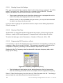
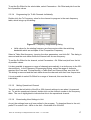
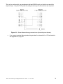
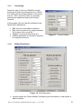
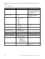
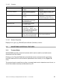
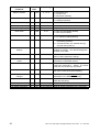
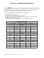
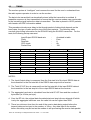
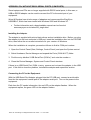
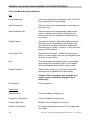
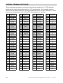
1
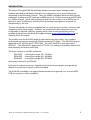
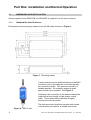
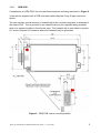
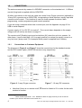
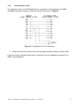
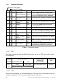
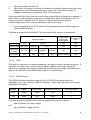
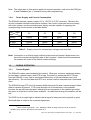
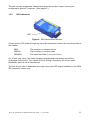
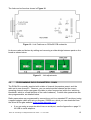
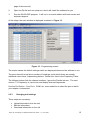
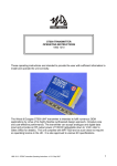
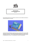
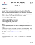
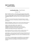
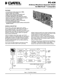
RSX RANGE OF INTELLIGENT MODEMS
USER GUIDE
1892 1139
Figure 1 - RSX Series Radio Modem
Figure 2 - OEM version
This manual is intended to provide you with sufficient information to install and operate an
RSX radio modem correctly.
1892 1139 - RSX Range of Intelligent Modems User Guide - v7.1 / Nov 2007
1
Contents
INTRODUCTION . . . . . . . . . . . . . . . . . . . . . . . . . . . . . . . . . . . . . . . . . . . . . . . . . . . . . . . 3
Part One: Installation and Normal Operation . . . . . . . . . . . . . . . . . . . . . . . . . . . . . . . . 4
1.1
DIMENSIONS AND INSTALLATION . . . . . . . . . . . . . . . . . . . . . . . . . . . . . . 4
1.1.1 Standard Die-Cast Enclosure . . . . . . . . . . . . . . . . . . . . . . . . . . . . . . 4
1.1.2 OEM PCB . . . . . . . . . . . . . . . . . . . . . . . . . . . . . . . . . . . . . . . . . . . . . 5
1.2
CONNECTIONS . . . . . . . . . . . . . . . . . . . . . . . . . . . . . . . . . . . . . . . . . . . . . 6
1.2.1 Connections to Customer Equipment . . . . . . . . . . . . . . . . . . . . . . . . 6
1.2.2 Connections to a PC . . . . . . . . . . . . . . . . . . . . . . . . . . . . . . . . . . . . 7
1.2.3 Detailed Information . . . . . . . . . . . . . . . . . . . . . . . . . . . . . . . . . . . . . 8
1.2.4 Power Supply and Current Consumption . . . . . . . . . . . . . . . . . . . . 10
1.3
DURING OPERATION . . . . . . . . . . . . . . . . . . . . . . . . . . . . . . . . . . . . . . . 10
1.3.1 Control Signals . . . . . . . . . . . . . . . . . . . . . . . . . . . . . . . . . . . . . . . . 10
1.3.2 LED Indications . . . . . . . . . . . . . . . . . . . . . . . . . . . . . . . . . . . . . . . 11
Part Two: Programming the Radio . . . . . . . . . . . . . . . . . . . . . . . . . . . . . . . . . . . . . . .
2.1
HARDWARE LINK SETTINGS . . . . . . . . . . . . . . . . . . . . . . . . . . . . . . . . .
2.2
PROGRAMMING RADIO PARAMETERS - SXN50 . . . . . . . . . . . . . . . . .
2.2.1 Programming Adaptor for use with SNx50.exe software . . . . . . . .
2.2.2 Obtaining and Running the Programming Software . . . . . . . . . . . .
2.2.3 Changing unit settings . . . . . . . . . . . . . . . . . . . . . . . . . . . . . . . . . .
2.3
CHANGING CHANNEL USING SERIAL COMMANDS . . . . . . . . . . . . . . .
12
12
13
14
14
15
18
Part Three: Programming the Modem . . . . . . . . . . . . . . . . . . . . . . . . . . . . . . . . . . . . .
3.1
CHANGING MODEM PARAMETERS - WINSETGMSK . . . . . . . . . . . . . .
3.1.1 Adaptor Cable . . . . . . . . . . . . . . . . . . . . . . . . . . . . . . . . . . . . . . . .
3.1.2 Obtaining and Running the Programming Software . . . . . . . . . . . .
3.1.3 Connecting . . . . . . . . . . . . . . . . . . . . . . . . . . . . . . . . . . . . . . . . . . .
3.1.4 Editing Parameters . . . . . . . . . . . . . . . . . . . . . . . . . . . . . . . . . . . . .
3.2
WINSETGMSK ADDITIONAL FEATURES . . . . . . . . . . . . . . . . . . . . . . . .
3.2.1 Terminal Mode . . . . . . . . . . . . . . . . . . . . . . . . . . . . . . . . . . . . . . . .
3.2.2 Telemetry Test . . . . . . . . . . . . . . . . . . . . . . . . . . . . . . . . . . . . . . . .
3.2.3 Closing WinSetGMSK . . . . . . . . . . . . . . . . . . . . . . . . . . . . . . . . . .
3.3
CHANGING MODEM PARAMETERS USING SERIAL COMMANDS . . . .
20
20
20
20
21
21
23
23
24
25
25
Part Four: Additional Information . . . . . . . . . . . . . . . . . . . . . . . . . . . . . . . . . . . . . . . .
4.1
RANGE . . . . . . . . . . . . . . . . . . . . . . . . . . . . . . . . . . . . . . . . . . . . . . . . . . .
4.2
VARIANT MODELS . . . . . . . . . . . . . . . . . . . . . . . . . . . . . . . . . . . . . . . . . .
4.3
TIMING . . . . . . . . . . . . . . . . . . . . . . . . . . . . . . . . . . . . . . . . . . . . . . . . . . .
4.4
TECHNICAL SPECIFICATIONS . . . . . . . . . . . . . . . . . . . . . . . . . . . . . . . .
27
27
28
29
30
APPENDIX: PCs WITHOUT RS232 SERIAL PORTS (COM PORTS) . . . . . . . . . . . . . 31
APPENDIX: SXn50 RADIO PROGRAMMING SOFTWARE REFERENCE . . . . . . . . . . 32
APPENDIX: TERMINAL KEYSTROKES . . . . . . . . . . . . . . . . . . . . . . . . . . . . . . . . . . . . 36
2
1892 1139 - RSX Range of Intelligent Modems User Guide - v7.1 / Nov 2007
INTRODUCTION
The Wood & Douglas RSX Series Radio Modems are high-speed intelligent radio
modems providing a half-duplex data link over a distance of up to several kilometres,
depending on the frequency chosen. They use GMSK (Gaussian Minimum Shift Keying)
modulation to achieve an RF data rate of 4800 baud in a 12.5kHz channel and 9600 baud
in a 25kHz channel. Serial data is passed to and from the modem via an RS232 port at
speeds of up to 38,400 baud, and all buffering and radio management is carried out
transparently by the unit.
The unit will typically be used as supplied with no setup required, wired to customer data
equipment and a power supply. However, the modem and radio parameters are userconfigurable if required, either by sending serial codes or using proprietary set-up
software obtained from the Wood & Douglas website (www.woodanddouglas.co.uk) or
Sales at Wood & Douglas.
The modem uses the SXn50G range of radios which are high quality, very compact
synthesized transceivers producing 500mW maximum RF output. The SXn50G range is
approved to EN 300 220 and ETS 300 086. The UHF SX450G is also approved to
MPT1411. The RSXn50G is approved to ETS 300 113 making it universally attractive for
both telemetry and mobile radio data.
The three variants in the RSX series are:
RSX150G
RSX450G
RSX850G
covering the range 100 - 225MHz
covering the range 400 - 490MHz
covering the range 868 - 870MHz
collectively referred to as RSXn50.
Units can be ordered covering a frequency band within these ranges, and operate by
default on a particular frequency within that band.
The RSXn50 is available in a rugged diecast enclosure for general use, or as an OEM
PCB for inclusion in other equipment.
1892 1139 - RSX Range of Intelligent Modems User Guide - v7.1 / Nov 2007
3
1
1.1
Part One: Installation and Normal Operation
DIMENSIONS AND INSTALLATION
Unless supplied as an OEM PCB, the RSXn50G is supplied in a die-cast enclosure.
1.1.1
Standard Die-Cast Enclosure
Dimensions and mounting by means of four off M4 holes is shown in Figure 3.
Figure 3 Mounting details
A whip antenna may be attached directly to the BNC
connector, and in this case the unit would typically
be mounted vertically. The antenna must be in a
suitable position - for example, against a metal
panel would not be suitable. See Figure 4.
Otherwise, the connection to the antenna should be
made with a short length of high-quality coaxial
cable. This is particularly important at higher
frequencies to avoid losses.
The data connector should be secured with screws
to the bushes provided for a reliable connection.
Figure 4 - RSX in use
4
1892 1139 - RSX Range of Intelligent Modems User Guide - v7.1 / Nov 2007
1.1.2
OEM PCB
If supplied as an OEM PCB, the unit has dimensions and mounting as shown in Figure 5.
It can also be supplied with a PCB connector rather than the 9-way D-type connector
shown.
The unit requires a small amount of heatsinking for the on-board regulator to dissipate of
the order of 2W. This is provided in the cased version by the regulator being screwed
down to a supporting pillar in the diecast case. The heatsink tab is connected to system
0V, and so requires no insulators where the heatsink may be grounded.
Figure 5 - OEM PCB version mounting details
1892 1139 - RSX Range of Intelligent Modems User Guide - v7.1 / Nov 2007
5
1.2
CONNECTIONS
The antenna connects by means of a 50O BNC connector on the standard unit. A 200mm
coaxial flying lead is supplied with the OEM PCB.
All other connections to the unit are made via a male 9-way D-type connector (optionally a
10-way IDC connector on an OEM PCB), incorporating a serial interface, supply input and
a remote on/off control. This interface is used for three separate functions: radio
programming, modem programming and normal operation.
If you are using a computer which has no serial port, see the Appendix on page 31 for
USB to serial adaptors.
A power supply of 5 to 15V DC is required1. The current drawn depends on the supply
voltage and unit activity as shown on page 10.
The remote on/off (Enable) input must be held low (0V) when the unit is to operate. At
other times, it can be held high (+2V to supply positive) to reduce the supply current to a
very low level (‘sleep mode’), for example where power is supplied from a battery.
1.2.1
Connections to Customer Equipment
The diagrams in Figure 6 and Figure 7 show the connections for the standard version
and the IDC header option (OEM PCB versions only) respectively.
Figure 6 - 9-way D-type connector
v
Figure 7 - 10-way IDC connector
Note that if there is no remote on/off, EN must be linked to 0V in order for the radio
modem to function.
1
Older models required 9V - 15V. Models are listed on page 28, and you can check the
model of your unit from the label on the bottom of it.
6
1892 1139 - RSX Range of Intelligent Modems User Guide - v7.1 / Nov 2007
1.2.2
Connections to a PC
The standard version of the RSXn50 may be connected to the serial port of an IBMcompatible personal computer using the connections shown in Figure 8.
Figure 8 - Connections to a PC serial port
v
These connections are also used when programming the modem (not the radio).
If you are using a computer which has no serial port, see the Appendix on page 31 for
USB to serial adaptors.
1892 1139 - RSX Range of Intelligent Modems User Guide - v7.1 / Nov 2007
7
1.2.3
Detailed Information
9-way D-type socket
10-way IDC header
Pin Pin Name
Function
In/out Remarks
1*
1*
DCD Data Carrier
RS232
Detect/Readback output
+10V = signal received, squelch open
-10V = no signal received, squelch closed.
In radio configuration mode, Readback.
2
3
RXD Data output from RS232
modem
output
Serial data from modem to external device
3
5
TXD Data input to
modem
RS232
input
Serial data from external device to modem
4
10
Input
5 to 15V DC supply (but see p.28 for
earlier models)
5
9
6
2
7
4
8
+V
Supply
GND 0V
EN
Ground System Ground
Enable
Input
Remote ON/OFF
0V = ON, +V (supply) or floating = OFF
RTS Ready To Send
input
RS232
input
From external device to RSX. See below.
6
CTS Clear To Send
output
RS232
output
From RSX to external device. See below.
9
8
PGM Program radio
RS232
input
Note: this input should be left open circuit
during normal use.
n/a
7
LED LED Status
Output
Logic low (0V) indicates No Lock error
(equivalent to orange LED indication)
Table 1 - Connection details
1.2.3.1
RTS
This table summarises what the RSXn50 expects to see on the RTS input under various
circumstances:
Modem
function
RTS
state
1.2.3.2
Normal Operation
Transmitting data
Idle
Programming
modem with
WinSetGMSK
High
Don’t care
True connection to PC
Programming
radio
Ignored
May be wired high or true connection
CTS
During normal operation, the RSXn50 takes the CTS output low to inhibit data input from
customer equipment. This is necessary under two circumstances:
8
1892 1139 - RSX Range of Intelligent Modems User Guide - v7.1 / Nov 2007
1.
2.
When the modem buffer is full
When there is a signal on-channel (indicated by the squelch being active high) and
transmission cannot therefore take place. When the TX squelch override is
enabled, transmission is permitted, and CTS remains high.
If the input data rate is less than the over-air data rate and there is therefore no danger of
buffer overrun, and transmission will never be inhibited by the squelch because the TX
squelch override is enabled, the CTS output can be left disconnected and the
corresponding input at the customer equipment can be wired high.
v
A true connection to the PC is essential when programming the modem using the
WinSetGMSK software.
This table summarises the RSXn50 CTS output state under various circumstances:
Normal Operation
Programming
modem with
WinSetGMSK
Programming
radio
N/A
N/A
N/A
N/A
TX Buffer state
Full
Squelch state
Don’t care
Inactive
TX Squelch
Override
Don’t care
Don’t care
Disabled
Enabled
N/A
N/A
CTS output
Low
High
Low
High
Used by software
N/A
1.2.3.3
Not full
Active
PGM
This input is used solely for radio programming, and has no function during normal use. It
should be left open-circuit, as any spurious signals applied could cause the SXn50
transceiver to become incorrectly programmed, indicated by the orange LED lighting or a
logic low on the LED output (OEM version with IDC connector only).
1.2.3.4
RS232 Levels
The RSXn50 provides a bipolar output of +10V on RS232 lines which should be
acceptable to the vast majority of RS232 interfaces. These levels have the conventional
significance, as follows:
Voltage
Name
Logic level
Assertion (RTS etc)
Bit value (data)
+10V
Space
High
True
0
-10V
Mark
Low
False
1
It will also accept non-RS232 level inputs as supplied by some PCs, where
high is between +2V and +supply
and
low is between -supply and 0V.
1892 1139 - RSX Range of Intelligent Modems User Guide - v7.1 / Nov 2007
9
Note: The information in this section applies to normal operation, and not to the PGM (pin
9) and Readback (pin 1) interface during radio programming.
1.2.4
Power Supply and Current Consumption
The RSXn50 requires a power supply of 5 to 15V DC (12V DC nominal)2. Because the
circuitry includes switched-mode power supplies, the current consumed varies inversely
with input voltage, and the external power supply must be capable of supplying the
corresponding current shown in the table below.
Input
5V
9V
12V
15V
Standby
100mA
70mA
60mA
50mA
RX
120mA
80mA
70mA
60mA
TX 5mW
120mA
80mA
70mA
60mA
TX 500mW
400mA
250mA
200mA
160mA
State
Table 2 - Supply current for various input voltages and activities
Note: Connection to a vehicle supply without proper external transient suppression can
cause the internal configuration data to be corrupted. Under these circumstances
the modem will revert to the default modem settings.
1.3
DURING OPERATION
1.3.1
Control Signals
The RSXn50 modem uses hardware flow control. Whenever customer equipment wishes
to send data, it should ensure that RTS is high. Provided it is answered with CTS high
from the RSXn50, it may start to send serial data at any of the permissible rates (see
specification). Do not send data with RTS low, as this could be interpreted as a command
code.
The RSXn50 brings CTS low if its transmit buffer becomes full and it cannot accept further
data to transmit at present. CTS is also brought low if transmission is not possible
because the squelch has operated, indicating received signals on the channel (provided
the option to override it has not been enabled). Any data sent during this condition will be
lost.
The DCD line is brought high to indicate that a signal is being received (squelch is open).
Received data is output to the customer equipment.
2
Older models required 9V - 15V. Models are listed on page 28, and you can check the
model of your unit from the label on the bottom of it.
10
1892 1139 - RSX Range of Intelligent Modems User Guide - v7.1 / Nov 2007
The unit normally suppresses transmission when the squelch is open, but may be
configured to ignore it if required. (See page 22.)
1.3.2
LED Indications
LED
Figure 9 - RSX Series Radio Modem
A three-colour LED visible through the top of the enclosure confirms the functional state of
the modem:
RED
GREEN
ORANGE
-
The modem is in transmit mode
The modem is in receive mode
The radio has failed (i.e. is out of lock).
Out of lock may occur if the radio has been programmed incorrectly such that the
synthesiser will not lock. One cause of this is setting a frequency out of the radio’s
bandwidth, which is set at manufacture.
The Out-of-lock state is duplicated as a logic low on the LED output available on the OEM
IDC connector version only.
1892 1139 - RSX Range of Intelligent Modems User Guide - v7.1 / Nov 2007
11
2
2.1
Part Two: Programming the Radio
HARDWARE LINK SETTINGS
Some options may be configured to user requirements using the on-board links as
detailed in the following table. With the exception of LK7, they all relate to radio
operation.
Link Function
Settings
LK3 +Vin/LED
closed when 9-way D-type connector is fitted
open when 10 way IDC is fitted*
LK4
closed
LK5 Over-air baud rate
closed
LK6
open
open
= 4800
open
= 9600
closed
LK7 EEPROM write enable (applies closed = enable (default setting)
to modem settings only)
open = write protect
LK9 +Vin/LED
open when 9-way D-type connector is fitted
closed when 10 way IDC is fitted*
LK10 LED enable
closed = enable (default setting)
open = disable
LK11 Transmitter power
1 - 2 = 500mW (default setting)
2 - 3 = 5mW
Table 3 - Link Settings
*OEM version only
These links are only accessible with the PCB removed from the enclosure, and are all on
the underside of the board (the radio module being on the upper side).
To remove the PCB from the enclosure:
1.
2.
Undo the four screws on the top of the unit and remove the lid.
Undo the two hexagonal bushes which secure the D-type connector, being careful
to retain the mounting plate and any nuts and washers from the inside of the
enclosure.
Undo the four screws which hold the PCB in place in the enclosure.
Lift the PCB out of the case, and pull the miniature coaxial connector out of the
radio module socket so that the PCB is completely free of the enclosure.
3.
4.
v
It is not necessary to remove the BNC antenna socket.
To reassemble the unit, reverse the instructions.
12
1892 1139 - RSX Range of Intelligent Modems User Guide - v7.1 / Nov 2007
The links can be found as shown in Figure 10.
Figure 10 - Link Positions on RSXn50 PCB underside
Links are made and broken by adding and removing a solder bridge between pads on the
board as shown below.
Figure 11 - Link adjustments
2.2
PROGRAMMING RADIO PARAMETERS - SXN50
The RSXn50 is normally supplied with a table of channel frequencies preset, and the
radio set to use channel 0. However, you can select another channel as the current
operating channel and/or reprogram the table to other frequencies (within the ‘switching
bandwidth’ which is a fixed attribute of the radio hardware). Certain other parameters are
also programmable, as detailed below.
Radio parameters are programmed by connecting a unit to a standard PC serial port using
a special adaptor cable and using a program, SXn50.exe, which you can download from
the Wood & Douglas website (www.woodanddouglas.co.uk).
v
If you are using a computer which has no serial port, see the Appendix on page 31
for USB to serial adaptors.
1892 1139 - RSX Range of Intelligent Modems User Guide - v7.1 / Nov 2007
13
Alternatively, you can send single serial bytes (for example, from a terminal) to select a
new channel. See page 18.
Modem parameters are set separately: see page 20.
2.2.1
Programming Adaptor for use with SNx50.exe software
The RSXn50 requires a special adaptor cable between itself and the PC serial port, which
also connects the 5 to 15V DC supply3. This cable is shown in Figure 12.
Figure 12 - Radio programming adaptor
v
2.2.2
.
1.
The RSXn50 provides true RS232 readback from pin 1, and so should be
compatible with any PC.
Obtaining and Running the Programming Software
v
If you have already obtained and installed the software, go to step 3
v
The Appendix on page 32 contains a reference covering the functions of the
SXn50.exe software.
Download the latest version of the programming software SXn50.exe from the
Wood & Douglas site on the internet. The URL (address) is:
www.woodanddouglas.co.uk
(In case of difficulty, contact Sales at Wood & Douglas, contact details on the last
3
Older models required 9V - 15V. Models are listed on page 28, and you can check the
model of your unit from the label on the bottom of it.
14
1892 1139 - RSX Range of Intelligent Modems User Guide - v7.1 / Nov 2007
page of this manual.)
2.
Open the Zip file and run setup.exe, which will install the software for you.
3.
Run the SXn50.EXE program. It will run in a normal window with both mouse and
keyboard support.
At this stage, the main window is displayed as shown in Figure 13.
Figure 13 - Programming screen
The screen shows the default settings which are displayed whenever the software is run.
The menu bar at the top lists a number of headings, under which there are usually
additional menu items, representing actions. Below this, there is the Frequency Table.
The leftmost column lists the channel numbers. Ignore the Parallel column. The next
column, TX Frequency, is used to set and display channel frequencies.
Use the Port Setup > Com Port > COM1 etc. menu selection to select the port to which
your adaptor is connected.
2.2.3
Changing unit settings
Three steps are necessary:
v
v
v
Upload information from the unit
Edit the information
Download information to the unit
1892 1139 - RSX Range of Intelligent Modems User Guide - v7.1 / Nov 2007
15
2.2.3.1
Reading Current Unit Settings
First, you must read into the computer what is in the unit’s memory at present. To do this,
press F5 or select Link > Read from the Unit > Upload All from SXn50G. The data
replaces the defaults on the screen and fills in the unit details.
v
The program insists that you do this before allowing you to reprogram the unit to
make it less likely that inappropriate values be entered.
v
However, once you have uploaded during a session, you may edit and download
the data to as many units as you wish.
If you just want to change the operational channel, skip to section Setting Operational
Channel on page 17.
2.2.3.2
Selecting Table Type
The SXn50G can hold either a table of 80 individually-chosen Tx frequencies and Rx
offsets, or a table of 256 equally-spaced Tx frequencies all with the same Rx offset.
To select the table type, select Parameters > Number of Channels > 80 or 256.
2.2.3.3
Programming 256 Channels as a Block
It is necessary to specify the starting frequency (the lowest, corresponding to channel 0),
a spacing or step value, and an Rx offset. The spacing is expressed in multiples of the
Comparison Frequency (including 0, which makes all frequencies the same).
Double-click the Tx Frequency value for channel 0 in the main frequency table, which
brings up this dialog:
Figure 14 - Frequency Programming Dialog
v
The list displays all valid values for the starting frequency, that is, frequencies
within the switching bandwidth which are multiples of the Comparison Frequency.
Select a Table Start frequency from the list and a Table Step and click OK. The dialog is
removed and the main table shows the channel frequencies.
16
1892 1139 - RSX Range of Intelligent Modems User Guide - v7.1 / Nov 2007
To set the Rx Offset for the whole table, select Parameters > Rx Offset and pick from the
list of possible values.
2.2.3.4
Programming Up To 80 Channels Individually
Double-click the Tx Frequency value for the channel to program in the main frequency
table, which brings up this dialog:
Figure 15 - Frequency Programming Dialog
v
Valid values for the starting frequency are frequencies within the switching
bandwidth which are multiples of the Comparison Frequency.
Select a Table Start frequency, ignoring the other parameters, and click OK. The dialog is
removed and the main table shows the channel with its new frequency.
To set the Rx Offset for the channel, select Parameters > Rx Offset and pick from the list
of possible values.
It is also possible to program a range of channels automatically in a similar way to the 256
channel block. In the Frequency Programming Dialog, select the range of channels
required (the From and To drop-downs), a Table Start and Channel Step, and click OK.
The dialog is removed and the main table shows the channels with their new frequencies.
It is not possible to select Rx Offset for a range of channels; this must be done
individually.
2.2.3.5
Setting Operational Channel
The unit must be told which of the 80 or 256 channel settings to use when it is powered
up. To set the operational channel, double-click on the channel number in the frequency
table. The row is highlighted to indicate that this is the operational channel.
2.2.3.6
Downloading New Settings to Unit
As yet, the settings have only been edited in the program. To download them to the unit,
press F6 or select Link > Write to the Unit > Download All to SXn50G
1892 1139 - RSX Range of Intelligent Modems User Guide - v7.1 / Nov 2007
17
v
This is only permitted if the Read from Unit command was previously used to
upload settings at some point during the session.
v
If you did not do this, save the configuration to disk, read the unit, and then retrieve
the configuration again. See below.
2.2.3.7
Completing Programming
This completes programming and the unit may be disconnected. It is not necessary to
switch off power or stop the program first.
2.2.3.8
Programming Further Units
Further units may be programmed by disconnecting one unit and connecting the next,
which may be done without switching the power off.
Proceed as above, downloading the configuration when all the channel parameters are
correct. For identically-programmed units, downloading is all that is necessary.
2.2.3.9
Saving and Retrieving Configurations
It is possible to save and retrieve configurations on disk for later use.
To save a new configuration, select File > Save Parameters As. To save a previously
saved configuration, select File > Save Parameters.
To retrieve a configuration, overwriting any existing configuration on the screen, select
File > Load Parameters.
v
2.3
This feature is also useful if you find that you cannot program a unit because you
omitted to read it first. Save your edited configuration, read the unit, then retrieve
the configuration.
CHANGING CHANNEL USING SERIAL COMMANDS
The channel can be changed by sending a serial channel number 0-255 as a single
RS232 byte on pin 9 (PGM). The protocol is:
9600 baud, RS232 levels, 1 start bit - 8 bit data - no parity - 1 stop bit
Single-byte, channel number in binary, LSB first (decimal 0 to 255)
Idle state for at least 40ms before and after byte.
As soon as the message is recognised as a valid command, the channel is changed. No
confirmation is required, and the setting is remembered during unit power off.
18
1892 1139 - RSX Range of Intelligent Modems User Guide - v7.1 / Nov 2007
This can be achieved by any equipment with an RS232 serial port which can send the
required byte. Only the TXD (to pin 9) and ground (to pin 5) connections are required.
Figure 16 - Serial channel change connections (terminal pinout shown)
v
If you use a terminal, the equivalent keystrokes for channels 0 to 127 are listed in
the appendix on page 36.
1892 1139 - RSX Range of Intelligent Modems User Guide - v7.1 / Nov 2007
19
3
3.1
Part Three: Programming the Modem
CHANGING MODEM PARAMETERS - WINSETGMSK
v
Modem parameters may be protected from change by a hardware link setting
described on page 12.
If you want to change modem parameters, they can be programmed by connecting a unit
to a standard PC serial port and using a program, WinSetGMSK.exe, which you can
download from the Wood & Douglas website, www.woodanddouglas.co.uk.
It is also possible to program the modem using command sequences of serial bytes. See
page 25.
Radio parameters are set separately: see page 13.
3.1.1
Adaptor Cable
The unit should be connected to the computer serial port using the type of cable shown in
Figure 8 on page 7. The RTS and CTS connections are essential in this case.
3.1.2
v
1.
Obtaining and Running the Programming Software
If you have already obtained and installed the software, go to step 3
Download the latest version of the programming software WinSetGMSK.exe from
the Wood & Douglas site on the internet. The URL (address) is:
www.woodanddouglas.co.uk
(In case of difficulty, contact Sales at Wood & Douglas, contact details on the last
page of this manual.)
2.
Open the Zip file and run setup.exe, which will install the software for you.
3.
Run the WinSetGMSK program. It will run in a normal window with both mouse
and keyboard support.
At this stage, the main window is displayed but behind a dialog shown in Figure 17.
20
1892 1139 - RSX Range of Intelligent Modems User Guide - v7.1 / Nov 2007
3.1.3
Connecting
Select the type of unit (e.g. RSX450) and the
serial port to which it is connected (e.g. COM1).
Try clicking the Auto Detect button to connect to
the unit. If the connection fails, try manually
selecting the speed and parity and clicking
Connect.
If the program tells you that the connection has
failed, likely reasons are:
v
v
v
v
3.1.4
RSX unit not connected to serial port
RSX unit not powered (or supply less than
9V for early units, see p.28)
Adaptor not correctly wired (see p.7)
Another application on the same computer
is using the serial port.
Figure 17 - Connect dialog
Editing Parameters
Figure 18 - Edit Parameters
v
A green square by ‘Control Modem’ indicates a good connection; a red square, a
bad connection.
1892 1139 - RSX Range of Intelligent Modems User Guide - v7.1 / Nov 2007
21
This tab allows you to read and set the values of parameters and control the modem, as
follows.
3.1.4.1
Parameters
Modem Parameter
Range of Values
Source address
0 to 255
This is the identity of the modem.
It only accepts messages bearing
this address as the destination,
and adds it as the source address
with all sent packets.
Default is 10
Destination address
0 to 255
The identity of the intended
recipient of a message.
Default is 10
Baudrate (RS232)
0 = 9600
1 = 19200 (default)
2 = 300
3 = 600
4 = 1200
5 = 2400
6 = 4800
7 = 38400
Parity (RS232)
0 = no parity
1 = odd parity
2 = even (default)
Modem Mode
0 = transmitter only
1 = receiver only
2 = transceiver (default)
Maximum frame length
0 = 64 bytes
1 = 128 bytes (default)
Transmitter start delay
0 to 255
x 5ms. Default 2 = 10ms
Transmitter stop delay
0 to 255
Milliseconds. Default = 1ms
Preamble message length
20 - 225
Length in bytes. Default = 20
CRC check
0 = CRC check disabled (default)
1 = CRC check enabled
Enable Command Mode
1=
0=
Tx Override
22
Notes
The modem works with 8 data bits
and parity
Command mode always
enabled when not
transmitting.
Command mode only
enabled during 4
seconds after power-up.
0 = Tx Override disabled
1 = Tx Override enabled (default)
Enables transmission even if the
squelch registers received signal
on channel.
1892 1139 - RSX Range of Intelligent Modems User Guide - v7.1 / Nov 2007
3.1.4.2
Controls
Command button
Function
Notes
Reset Modem
This command re-initialises the
modem.
Parameter settings are not
affected.
Set Factory Defaults
Enter all default parameter
settings and re-initialise the
modem.
You are asked to confirm. The
default settings are as listed in
this table.
Save to EEPROM
Save all parameters in EEPROM
memory.
If you save new communications
parameters, you will have to
reconnect using File > Connect.
Get Parameters
Read the parameters from the
unit EEPROM into the Edit
Parameters boxes.
Data port check
A message box indicates
success or failure.
Activate TX test mode
The modem enters test mode
and sends a continuous
1100110011.... pattern. The
output continues until the button
(now labelled Deactivate Test
Mode) is clicked again.
Leave Command Mode
Returns the modem to its normal
state, waiting to transmit data or
go back into command mode.
3.1.4.3
The button changes its legend to
Enter Command Mode.
Modem Properties
Displays unit type (e.g. RSX450) and software (firmware) version.
3.2
WINSETGMSK ADDITIONAL FEATURES
3.2.1
Terminal Mode
WinSetGMSK provides a terminal emulator which can be used to send and receive
characters from the modem.
Clicking on the Terminal Mode tab automatically leaves command mode and enters
terminal mode with the communications parameters most recently in use (Figure 19,
over).
The terminal can be used like any other to transmit and receive characters over the air, or
control the modem manually as described on p.25.
1892 1139 - RSX Range of Intelligent Modems User Guide - v7.1 / Nov 2007
23
Figure 19 - Terminal Mode
3.2.2
Telemetry Test
This test sends a string which you type in (or the default string of a number and the date
and time, if you leave the field blank) over the air, at intervals determined by the Delay
field.
Select the Telemetry Test tab, which automatically leaves command mode, fill in the
details and click Start.
The button legend changes to Stop: click it to end the test.
Figure 20 - Telemetry Test mode
24
1892 1139 - RSX Range of Intelligent Modems User Guide - v7.1 / Nov 2007
3.2.3
Closing WinSetGMSK
To end the session with WinSetGMSK, click the X icon at the top right-hand corner of the
window.
If you have not saved changes to the modem parameters, you will be given the
opportunity before the program closes.
The unit returns to normal mode if it was in command mode.
3.3
CHANGING MODEM PARAMETERS USING SERIAL COMMANDS
We recommend using the WinSetGMSK software as an easy and reliable method of
programming modem features. However, it is also possible to use sequences of serial
commands from another source to do this. A standard terminal such as the VT100 can
send some, but not necessarily all, of the codes required.
Serial commands require the same connections as for data or WinSetGMSK.
In order to enter command mode, the RSXn50 must be in receive, not transmit mode, and
be sent the ASCII characters [escape]# – that is, two bytes of numerical value <27> and
<35>. These must be the first two characters since the unit went into receive mode. (This
may conveniently be arranged by lowering RTS briefly and raising it again.) When the
unit accepts the command, it responds with the characters [CR][LF].
Commands may then be given by sending a single-byte command code, sometimes
followed by a second parameter value byte, depending on the command. Parameter
bytes hold a numerical value between 0 and 255, not a character, and may therefore not
be available on a terminal. Commands and parameters are shown in the table. Each
successful command is responded to with [CR][LF].
To terminate command mode, send the command S (to save) or [escape] to cancel.
Modem Parameter or
Command
Command
Byte
Parameter byte
Char Value
Decimal value
Notes
Source address
a
97
0 to 255
Default is 10
Destination address
b
98
0 to 255
Default is 10
RS232 baudrate
d
100
0 to 7
Parity
e
101
0, 1 or 2
0 = 9600
1 = 19200 (default)
2 = 300
3 = 600
4 = 1200
5 = 2400
6 = 4800
7 = 38400
0 = no parity
1 = odd parity
2 = even (default)
NOTE: The RSX works with 8 data bits + parity
1892 1139 - RSX Range of Intelligent Modems User Guide - v7.1 / Nov 2007
25
Modem Parameter or
Command
Command
Byte
Parameter byte
Notes
Mode of modem
f
102
0, 1 or 2
Maximum frame length
h
104
0 or 1
Transmitter start delay
i
105
0 to 255
Units of 5ms. Default 2 = 10ms
Transmitter stop delay
j
106
0 to 255
Units of 0.5ms. Default 10 = 5ms
Preamble msg length
k
107
20 - 225
Length in bytes. Default = 20
CRC check
l
108
0 or 1
0 = CRC check disabled (default)
1 = CRC check enabled
Tx Override
m
109
0 or 1
0 = Tx override disabled
1 = Tx override enabled (default)
Command mode access
X
88
0 or 1
1 = Command mode always enabled when not
transmitting (default).
0 = Command mode only enabled during 4
seconds after power-up.
Revert to default
settings
D
68
no second byte Enter all default parameter settings and reinitialise the modem. The default settings are
as listed in this table.
Full reset
R
82
no second byte This command re-initialises the modem but
does not affect parameter settings.
Save and exit command
mode
S
83
no second byte Leave command mode after saving all
parameters in EEPROM memory.
Test Mode
T
84
no second byte The modem enters test mode and sends a
continuous 1100110011.... pattern. The output
continues until another key is pressed.
List parameters
Z
90
no second byte Send all current parameter settings to the serial
port (with current baud rate and parity).
Abandon parameter
changes
ESC
27
no second byte Leave command mode without saving the
parameters in the EEPROM memory.
Output software version
?
63
no second byte Output as text on the serial port (with current
baud rate and parity).
Data port check
!
33
no second byte Modem answers with ?
List default parameters
Y
89
no second byte Send all default parameters to the serial port.
26
0 = transmitter only
1 = receiver only
2 = transceiver (default)
0 = 64 bytes
1 = 128 bytes (default)
1892 1139 - RSX Range of Intelligent Modems User Guide - v7.1 / Nov 2007
4
4.1
Part Four: Additional Information
RANGE
The following table gives an indication of the typical ranges to be expected between a
transmitter and receiver that have simple end-fed dipole antennas.
The following assumptions have been made in the calculations:
line-of-sight between antennas
0dB gain for the transmitter and receiver antennas
0dB loss for connectors and cables between the antenna and the radio connector
20dB fade and environmental margin
-100dBm received signal strength, allowing for the GMSK modulation
Range versus TX power
Frequency (MHz) Power (mW) Power (dBm) Range (km) Range (miles)
RSX150G
173
1mW
0
1.7
1.1
173
10mW
10
4.4
2.7
173
100mW
20
13.8
8.6
173
500mW
27
30.9
19.2
RSXn50G
458.5
1mW
0
0.5
0.3
458.5
10mW
10
1.6
1.0
458.5
100mW
20
5.2
3.2
458.5
500mW
27
11.7
7.3
RSX850G
869
1mW
0
0.3
0.2
869
10mW
10
0.9
0.6
869
100mW
20
2.8
1.7
869
500mW
27
6.2
3.9
1892 1139 - RSX Range of Intelligent Modems User Guide - v7.1 / Nov 2007
27
4.2
VARIANT MODELS
The RSX range of modems has been made in a number of variants. This manual is
generally applicable to all of them, but there are some variations, of which the most
important are listed below. In particular, earlier models require at least a 9V supply in
order to function correctly. Later models with a wider supply range may always be
substituted for earlier ones.
To find out which model you have, refer to the label on the device and look for a model
number of the form 01234 5678 A. The letter at the end may be ignored for the purposes
of this table.
Features
Model
number
range
Model
This
SXn50G
manual
9 - 15V 5 - 15V SXn50
radio
WD1604 WD2121 WD2135 fully
supply supply radio (Pb-free) board
board*
board applies
t
t
t
t
t
t
RSX850
t
t
t
01202 1501
RPS960
t
t
t
01208 1715 01208 2013
RSX450
t
t
t
01208 2014
RSX450G
01208 2015
RSX450G
01208 2105 01208 2108
RSX450G
01208 2109 01208 2112
RSX450G
01208 2113
01178 1700 01178 2101
RSX450
01178 2401
01178 2402
RSX150
01178 2501
t
t
t
t
t
t
t
t
t
RSX450G
t
t
01208 2114
RSX450G
t
t
01208 2401
01208 2409
RSX150
01208 2501 01208 2803
RSX850
01208 3001 01208 3004
RSX150
Other ranges
RSXn50G
t
t
t
t
t
t
t
t
t
t
t
t
t
t
t
t
t
t
Phasing
out
t
t
Phasing
in
t
* Has different fixing dimensions and is not supplied as an OEM board
28
1892 1139 - RSX Range of Intelligent Modems User Guide - v7.1 / Nov 2007
4.3
TIMING
The modem system is “intelligent” and removes the need for the user to understand how
the radio system operates in order to use the modem.
The data to be transmitted is automatically stored while the transmitter is enabled A
preamble sequence is then transmitted to ensure that the receive modem can synchronise
to the incoming signal before the data is transmitted. The data is placed in HDLC packets
with header and CRC information added.
This procedure introduces a delay to the through packet of data which depends on the
baud rates, the type of radio and the size of the input packets. The following table
overleaf gives timing information for the RSX450 using the SX450G transceiver. For the
tests, the following set-up was used:
Input/Output RS232 baud rate
Parity
Data bits
CRC check
Packet Size
-
As stated in table
Even
8
On
128
RF Baud Rate Packet Size (bytes) I/P-O/P Delay (ms) Total I/P-O/P Time (ms) Aggregate Baud Rate
RS232 baud rate = 9600
9600
42
80
130
3554
9600
332
125
540
6763
9600
2402
125
2950
8957
4800
42
141
191
2419
4800
332
283
890
4103
4800
2402
283
5235
5047
RS232 baud rate = 19200
9600
42
80
103
4485
9600
332
150
452
8080
9600
2402
150
2563
10309
NOTES :
1. The Input-Output delay is measured from the first start bit of the input RS232 data at
the transmitter to the first start bit of the RS232 data output at the receiver.
2. The Total I/P-O/P time is measured from the first start bit of the input RS232 data at
the transmitter to the last stop bit of the output RS232 data at the receiver.
3. The aggregate baud rate is calculated from the total I/P-O/P time and the number of
bytes sent (at 10 bits per byte).
4. Over the RF link, the original data formatted start and stop bits are stripped off which
is why the aggregate baud rate over the radio link can be higher than 9600.
5. There is a minimum time from the end of the receive data being output before the
transmit data can be input to the modem, of 10ms. Any data input to the modem
before this delay may be lost as the modem is still processing the receive data packet.
1892 1139 - RSX Range of Intelligent Modems User Guide - v7.1 / Nov 2007
29
4.4
TECHNICAL SPECIFICATIONS
Frequency range
: RSX150G 100 - 225MHz (banded, fixed at manufacture)
RSX450G 400 - 470MHz (banded, fixed at manufacture)
RSX850G 868 - 870MHz
Usable band depends on frequency, please enquire.
RF preset channels
: 80 (selectable via separate RS232 serial input, frequencies
programmable within band)
Channel programming : Table of 256 equally-spaced frequencies with common Rx-Tx
offset, or table of 80 individually-programmed frequencies and
Rx-Tx offsets.
Channel selection
: 64 channels maximum using 6-bit parallel logic line input.
256 channels maximum using serial RS232 data word.
Serial/parallel selection switchable in real time.
Channel spacing
: 12.5kHz/20kHz/25kHz available, fixed at manufacture
Data input/output
: RS232
RF Baud rate
: 4800 for 12.5kHz channel spacing and 9600 for 20kHz and
25kHz channel spacing (configurable)
Modulation type
: GMSK
Data input/output rate : 300, 600, 1200, 2400, 4800, 9600, 19,200 and 38,400 baud
(configurable)
Source address
: 0-255 (configurable)
Destination address
: 0-255 (configurable)
Number of data bits
: Fixed at 8. (Will accept 7 data bits with 8th bit parity: in this
case, set the modem parity to ‘None’).
Parity
: None, odd, even (configurable)
Handshaking
: RTS, CTS, DCD (squelch)
Supply voltage
: 5V - 15V DC negative earth
Supply current
: Varies with input voltage; see table on p.10
Tx/Rx switching time
: 20ms
RF power output
: 500mW (High); 5mW (Low) as standard (link-selectable); other
powers available
Interface connector
: male 9-way D-type connector
RF connector
: female BNC
Type approval
: ETS 300 113; EN 300 220; ETS 300 086. UHF version also
MPT1411.
Size overall
: 139 x 64 x 30mm (0.55 x 2.52 x 1.18")
Weight
: 670g (23.6 oz)
Operating temperature : -10%C to +55%C
Storage temperature
: -30%C to +70%C
General facilities
: LED confirming functional state (Tx, Rx, fail)
Power save facility
: Logic input provides on/off switching
Tx forcing mode
: Configures the modem to transmit regardless of squelch state
Packet size
: Configurable for 64 or 128 bytes.
For data packets <64, set modem to 64
For data packets >64, set modem to 128 (more efficient for
large data packets)
Cyclic Redundancy Check: Received data is checked and if a CRC error is detected the
packet is discarded. Set to ‘disable’ if using external error
checking or system can cope with some corrupt data.
30
1892 1139 - RSX Range of Intelligent Modems User Guide - v7.1 / Nov 2007
APPENDIX: PCs WITHOUT RS232 SERIAL PORTS (COM PORTS)
Some laptops and PCs are no longer supplied with RS232 serial ports; in this case, a
USB-to-RS232 adaptor can be used to connect the PC to the serial port of your
equipment.
Wood & Douglas have tried a range of adaptors and recommend the EasySync
US232B/LC, which has been tested with Windows 2000 and Windows XP.
v
Further information and a downloadable manual can be found at
www.easysync.co.uk/usbrs232_single.html.
Installing the Adaptor
The adaptor is supplied with printed instructions and an installation disc. Before you plug
the adaptor into the host computer’s USB port, insert the installation disc into its CD-ROM
drive, then follow the on-screen instructions for your version of Windows.
When the installation is complete, proceed as follows to find its COM port number:
1. Open the Control Panel (Start, Settings, Control Panel) and open the System control.
2. Select Hardware, Device Manager and expand the Ports (COM & LPT) folder.
3. Find the entry labelled “USB Serial Port (COM n)” and note the number n.
4. Close the Device Manager, System and Control Panel windows.
If there is no USB Serial Port (COM n) entry, remove and re-insert the adaptor in the USB
port. If this fails to clear the problem, uninstall the adaptor and repeat this section.
Connecting the PC to the Equipment.
With the USB Serial Port Adaptor plugged into the PC USB port, connect a serial cable
from the the equipment’s serial port to the adaptor serial port. Turn on the power to the
equipment.
Each time the PC sends information, the red LED on the adaptor flashes. When the
equipment replies, the green LED on the adaptor flashes.
1892 1139 - RSX Range of Intelligent Modems User Guide - v7.1 / Nov 2007
31
APPENDIX: SXn50 RADIO PROGRAMMING SOFTWARE REFERENCE
Top Level Menu Bar (Outer Window)
File
Load Parameters
Load a pre-stored set of parameters in a *.WXP file
from a standard File Open dialog.
Save Parameters
Save the current set of parameters, overwriting the
previous ones.
Save Parameters As
Save the current set of parameters under a new
name. A default name is given which you can
change, and you can navigate to the directory of
your choice.
Saving Options
Controls the format in which information is saved.
Provided you are programming an SXn50G, you
should save in the default Format 2, allowing 80
channels with IF offsets. Format 1 is only used with
legacy SX450 modules.
Save Report File
Save the current report. A default name is given
which you can change, and you can navigate to the
directory of your choice.
Print
Print the current set of parameters; only available
when Report File window is open. The currently
selected Windows default printer will be used.
Update Firmware
Replace the firmware in a unit with a binary file
selected from a standard File Open dialog.
Caution: This can render a unit unusable and
require repairs by Wood & Douglas if done
incorrectly.
Exit Program
Exit the program.
Parameters
Reference Osc
Fixed in hardware, display only.
Comparison Frequency
Fixed in hardware, display only.
Channel Step Size
Multiple of the Comparison Frequency
Number of Channels
80 (individually programmed) or 256 (programmed
as a table)
32
1892 1139 - RSX Range of Intelligent Modems User Guide - v7.1 / Nov 2007
Select Rx Offset
A number of choices, multiples of the Comparison
Frequency, are offered.
Link
Read from Unit
Reads data from the unit into the program, which is
then displayed on the screen. Until this command
has been issued, no data can be downloaded to
the unit.
Write to Unit
Downloads data from the program to the unit. This
command can only be issued after a Read from Unit
command has been issued during the current
session.
Send e-mail
Causes your default email application to create a
new blank email addressed to Wood & Douglas
technical support with the subject “SNx50".
Port Setup
Com Port
Allows you to select one of the COM (serial) ports on
your machine to communicate with the SXn50G.
View
Main Menu
Turns on and off display of the Main Menu window.
Internal EEPROM
This displays the contents of the unit’s EEPROM in a
separate window. The data displayed is for the
functions and channels displayed on the main
screen at that time. Data can be hand-modified by
highlighting the data and over-writing it. Note that
the type of data in each field is displayed at the
bottom of the window.
Caution:This should only be carried out with full
knowledge of the internal working of the SXn50G.
It can render a unit unusable and require repairs
by Wood & Douglas if done incorrectly.
While this window is displayed, no access is
available to the main window. The window must be
cleared down by clearing the check mark against it in
the View menu.
Report File
Displays a report on the current setup shown in the
main menu which can be printed if you wish.
1892 1139 - RSX Range of Intelligent Modems User Guide - v7.1 / Nov 2007
33
Help
About
Displays information about Wood & Douglas,
including website and contact details.
Check for GUI Update
Checks the Wood & Douglas website for updates
and offers to update your GUI if appropriate.
Main Menu - Frequency Table (Inner Window)
Channel Table
The Channel Table shows the following parameters for each of the 80 or 256 channels, as
appropriate:
Channel No
Parallel (logic lines) code required to select this
channel, where 1 represents a connection to 0v,
closed contact to 0V or logic low.
Tx Frequency
The transmit frequency.
Rx Frequency
The receive frequency (which may be different if an
Rx offset has been selected).
Rx Offset
The amount by which the Rx frequency is higher
than the Tx frequency.
Unit Information
This box is display only and cannot be edited.
File Name
The name of the firmware running in the unit.
File Version
The version of firmware running in the unit.
File Date
The date of the firmware running in the unit
S/N
The serial number of the unit.
Number of Channels
How many channels are programmed and may be
selected during operation.
Maximum Frequency
The software assumes a 5MHz switching bandwidth
to calculate the Maximum Frequency from the
Minimum Frequency and uses this to calculate the
frequencies in the drop-down list displayed when
selecting channel frequencies.
34
1892 1139 - RSX Range of Intelligent Modems User Guide - v7.1 / Nov 2007
Minimum Frequency
The minimum frequency refers to the transmit band,
and is used by the software as a base-line for all
other frequency information. The software will not
allow a channel to be set to a frequency below this
minimum (or, in the case of a received channel, this
frequency plus the receive offset). This frequency is
stored in the non-volatile EEPROM in the unit.
1892 1139 - RSX Range of Intelligent Modems User Guide - v7.1 / Nov 2007
35
APPENDIX: TERMINAL KEYSTROKES
These keystrokes generate a serial byte output from a standard (e.g. VT100) terminal
which can be used to select channels 0 to 127 in serial mode. For example, to select
channel 36, key Shift+4 (dollars), which generates the byte 00100100, decimal 36. Other
keystrokes may generate codes 128 to 255, depending on the terminal.
No Keystroke
0
Ctrl @
1
Ctrl A
2
Ctrl B
3
Ctrl C
4
Ctrl D
5
Ctrl E
6
Ctrl F
7
Ctrl G
8
Ctrl H
9
Ctrl I
10
Ctrl J
11
Ctrl K
12
Ctrl L
13
Ctrl M
14
Ctrl N
15
Ctrl O
16
Ctrl P
17
Ctrl Q
18
Ctrl R
19
Ctrl S
20
Ctrl T
21
Ctrl U
22
Ctrl V
23
Ctrl W
24
Ctrl X
25
Ctrl Y
26
Ctrl Z
27
Ctrl [
28
Ctrl \
29
Ctrl ]
30
Ctrl ^
31
Ctrl _
36
No Keystroke
32 <SPACE>
33
Shift 1
34
Shift ‘
35
Shift 3
36
Shift 4
37
Shift 5
38
Shift 7
39
‘
40
Shift 9
41
Shift 0
42
Shift 8
43
Shift =
44
,
45
46
.
47
/
48
0
49
1
50
2
51
3
52
4
53
5
54
6
55
7
56
8
57
9
58
Shift ;
59
;
60
Shift ,
61
0
62
Shift .
63
Shift /
No Keystroke
64
Shift 2
65
Shift A
66
Shift B
67
Shift C
68
Shift D
69
Shift E
70
Shift F
71
Shift G
72
Shift H
73
Shift I
74
Shift J
75
Shift K
76
Shift L
77
Shift M
78
Shift N
79
Shift O
80
Shift P
81
Shift Q
82
Shift R
83
Shift S
84
Shift T
85
Shift U
86
Shift V
87
Shift W
88
Shift X
89
Shift Y
90
Shift Z
91
[
92
\
93
]
94
Shift 6
95
Shift -
No Keystroke
96
`
97
A
98
B
99
C
100
D
101
E
102
F
103
G
104
H
105
I
106
J
107
K
108
L
109
M
110
N
111
O
112
P
113
Q
114
R
115
S
116
T
117
U
118
V
119
W
120
X
121
Y
122
Z
123
Shift [
124
Shift \
125
Shift ]
126
Shift `
127
Del
1892 1139 - RSX Range of Intelligent Modems User Guide - v7.1 / Nov 2007
Wood & Douglas Ltd, Lattice House
Baughurst, Tadley, Hants, RG26 5LP
Tel:+44 (0)118 981 1444 Fax: +44 (0)118 981 1567
email: [email protected]
website: www.woodanddouglas.co.uk
1892 1139 - RSX Range of Intelligent Modems User Guide - v7.1 / Nov 2007
, Wood & Douglas Ltd 2007
37