1
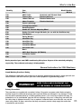
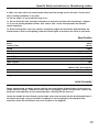
Code 501245
AWSL Woodturning
Lathe
Hole assembly instructions including extension bed
OPTIONAL EXTENSION BED
Code 503035
Axminster Tool Centre,
Unit 10 Weycroft Avenue, Axminster, Devon EX13 5PH
axminster.co.uk
Index of Contents
Page No.
Index of Contents
Declaration of Conformity
What’s in the Box
General Instructions for 230V Machines
Specific Safety Instructions for Woodturning Lathes
Specification
Initial Assembly
Parts Description and Identification
Changing the Speed
Parts Breakdown/List
Notes
02
02
03
03-04
04-05
05
05-06
07-08-09-10
11
12-13-14
15
Declaration of Conformity
Copied from CE Certificate
The undersigned, F. Mocking authorised by
Laizhou Chunlin Machinery Factory
No. 275 Wenquan East Road
Laizhou,Shandong 261400
P.R. China declares that this product
manufactured by Laizhou Chunlin Machinery Factory
is in compliance with the following standards or
standardisation documents in accordance with Council
Directives
93/68/EEC
Model number MC1018 (Wood Lathe)
Please read the Instruction Manual prior to using your new machine; as well as the
operating procedures for your new machine, there are numerous hints and tips to help
you to use the machine safely and to maintain its efficiency and prolong its life. Keep this
Instruction Manual readily accessible for any others who may also be required to use the
machine.
symbols below advise that you follow the correct
Warning The
safety procedures when using this machine.
Fully read manual
and safety instructions
before use
02
Ear protection
should be worn
Eye protection
should be worn
Dust mask
should be worn
HAZARD
Motor gets hot
What’s in the Box
Quantity
Item
Model Number
Box 1
MC1018
AWSL Lathe
Headstock and Tailstock fitted
Toolrest Arm
Fitted to lathe bed
140mm Tool rest
Fitted to Toolrest arm
80mm Faceplate
Fitted to Headstock
Packet containing:4 Prong Drive Centre
Revolving Centre
Handle for Tailstock Adjusting Wheel
Rubber Feet with integral M8 bolts (for use with the Bed Extension)
Flat Washers
Spring Washers
8mm Allen Key
6mm Allen Key
3mm Allen Key
Instruction Manual
Guarantee Card
Box 2
AWSL Bed Extension (OPTIONAL)
Instruction Leaflet
Bolts
1 No.
1 No.
1 No.
1 No.
1 No.
1 No.
1 No.
1 No.
2 No.
2 No.
2 No.
1 No.
1 No.
1 No.
1 No.
1 No.
1 No.
1 No.
2 No.
Having unpacked your new AWSL woodturning lathe please dispose of the unwanted packaging
responsibly. The cardboard packaging is biodegradable.
General Instructions for 230V Machines
Good Working Practices/Safety
The following suggestions will enable you to observe good working practices, keep yourself and
fellow workers safe and maintain your tools and equipment in good working order.
!
WARNING!!
KEEP TOOLS AND EQUIPMENT OUT
OF THE REACH OF YOUNG CHILDREN
Primary Precautions
These machines are supplied with a moulded 13 Amp. Plug and 3 core power cable. Before using the
machine inspect the cable and the plug to make sure that neither are damaged. If any damage is visible
have the tool inspected/repaired by a suitably qualified person. If it is necessary to replace the plug, it is
preferable to use an ‘unbreakable’ type that will resist damage. Only use a 13 Amp plug, and make sure
the cable clamp is tightened securely. Fuse as required. If extension leads are to be used, carry out the
same safety checks on them, and ensure that they are correctly rated to safely supply the current that
is required for your machine.
03
General Instructions for 230V Machines
Work Place/Environment
Make sure when the machine is placed that it sits firmly on the bench or stand, that it does not rock, that it
is sufficiently clear of adjacent obstacles so that you have unimpeded access to all parts of the machine.
The machine is designed for indoor use, do not use when or where it is liable to get wet. Keep the machine
clean; it will enable you to more easily see any damage that may have occurred. Clean the overall machine
with a damp soapy cloth if needs be, do not use any solvents or cleaners, as these may cause damage to
any plastic parts or to the electrical components. Clean the machined components with a lightly oiled cloth.
If the machine is liable to be standing idle for any length of time a light coat of machine or spray oil will
minimise rusting.
!
Keep the work area as uncluttered as is practical, this includes personnel as well
as material. Under no circumstances should CHILDREN be allowed in work areas.
It is good practice to leave the machine unplugged until work is about to commence, also make
sure to unplug the machine when it is not in use, or unattended. Always disconnect by pulling on
the plug body and not the cable. Once you are ready to commence work, remove all tools used
in the setting operations (if any) and place safely out of the way. Re-connect the machine.
Carry out a final “tightness” check e.g. chuck or face plate, workpiece, tool rest, etc., check that
the correct speed has been selected.
Make sure you are comfortable before you start work, balanced, not reaching etc. If the work
you are carrying out is liable to generate flying grit, dust or chips, wear the appropriate safety
clothing, goggles, gloves, masks etc. If the work operation appears to be excessively noisy, wear
ear-defenders. If you wear your hair in a long style, wearing a cap, safety helmet, hairnet, even a
sweatband, will minimise the possibility of your hair being caught up in the rotating parts of the
tool, likewise, consideration should be given to the removal of rings and wristwatches, if these
are liable to be a ‘snag’ hazard. Consideration should also be given to non-slip footwear, etc.
Do not work with cutting tools of any description if you are tired, your attention is wandering or
you are being subjected to distraction. A deep cut, a lost fingertip or worse; is not worth it!
Above all, OBSERVE…. make sure you know what is happening around you, and USE
YOUR COMMON SENSE.
Specific Safety Instructions for Woodturning Lathes
1. Do not use ‘split’ work pieces.
2. Always start at the lowest speed when starting a new task.
3. Try to render a new workpiece “round” (or as close as is practical) before turning.
4. Check that the tool rest is at or slightly below the centre line of the workpiece.
5. Check the workpiece is securely mounted in the lathe before switching on the power.
6. Rotate the workpiece by hand, to check that it is:- centralised, clear of the tool rest, not ‘split’
or has loose knots.
7. Where lathes have the facility to be reversed; check the machine is rotating in the correct
direction.
8. If your lathe has the facility to run in reverse, you must ensure that the mounting
accessories (chucks, faceplates etc.,) can be ‘locked’ onto the lathe mandrel, and in the case of
chucks have some form of security device to prevent them ‘unwinding’ during reverse
operation.
04
Specific Safety Instructions for Woodturning Lathes
9. Make sure your tools are stored/racked away from the turning area of the lathe. Do not reach
over a rotating workpiece at any time.
10. Do not ‘dig in’ or try to take too large a cut.
11. Do not leave the lathe running unattended; or leave the machine until everything is stopped.
12. If you are turning between centres with ‘softish stuff’, check and reposition the tailstock
centre frequently.
13. Some turning tools may have specific sharpening angles that have been determined by the
manufacturers; when re-sharpening, adhere to these angles to maximise the finish of your work.
Specification
Model
Product Code
Rating
Power
Speed
Spindle Taper
Spindle Thread
Taper Tailstock
Distance Between Centres
Max Diameter over Bed
Overall L x W x H
Weight
AWSL
501245
Hobby
375W
(5) 760-3,200rpm
2MT
1” x 8tpi (Ref T04M)
2MT
440mm(17”),
965mm (38”) with extension
240mm
865 x 205 x 365mm
38kg
Initial Assembly
Before commencing assembly, please read the parts description & identification so that you can
readily identify the parts. Remove the lathe from its packaging. Stand it on the bench. Loosen the
banjo lock and reposition to the required position, similarly with the tool rest.
Locate the handle for the tailstock control wheel and screw securely into the pre-threaded hole in
the wheel rim flange, using a flat blade screwdriver. If you are going to fit the optional bed
extension, follow the instructions that are in the box or see page 06.
05
Initial Assembly
Optional Extension Bed
Step 2
Remove the plate and
locate the holes.
Step 1
Remove the two screws.
Bolt holes
Screw driver
Dowel holes
Typ. dowels
Step 3
Line up the extension bed
locating dowels with the two
dowel holes in the casting.
Step 5
Clamp the
tailstock across
the join to align
the beds. Then
tighten the
holding bolts
securely.
06
Step 4
Slide the extension bed carefully
but firmly into place. Insert the
bolts and tighten, finger tight.
Step 6
Refit end cover
plate to extension
bed.
Wood lathe
Extension bed
Parts Description and Identification
AWSL Front View
Faceplate
Drive centre
Headstock
spindle
handle
Tailstock
handle
Headstock
Tailstock
Revolving Centre
Banjo
Lathe bed
Banjo lock
On
Off
Motor assembly
Shaped handle
On/off Switch
07
Parts Description and Identification
Lathe Bed
Cast Iron frame with ground top surfaces and 4 leg extrusions, the leg
extrusions have large rectangular flanges for strength and are also used
to support the ON/OFF switch assembly at the tailstock end and the
motor mounting plate, drive pulley assembly at the headstock end.
There are threaded holes in the base of the legs to accept the integral
bolts of the rubber feet. The far headstock end has a flat metal plate
cover to guard the drive pulley cluster. The far tailstock end has four
threaded holes to accept the mounting bolts for the optional bed
extension. If the bed extension is not used the mounting face is covered
by a small metal plate (secured by 2 screws, which also have threaded
fixing holes in the end of the bed). The metal plate also prevents the
tailstock being slid off the end of the bed. If the bed extension is fitted,
the plate should be transferred to the end of the extension.
Headstock
Tower casting, which is bolted to the bed. It has housings for the
bearings that carry the headstock spindle. At the rear of the headstock
is an open void to give access to the driven pulley cluster, it is guarded
by a flat metal plate cover.
Headstock
Spindle
A steel spindle threaded 1” UNC (8 tpi) to mount faceplates, chucks etc.
The spindle is bored out to accept 2MT drive centres et al. The driven
pulley cluster is keyed onto the shaft between the two mounting
bearings. There is a small handwheel mounted on the outer end of the
spindle to facilitate hand rotation, whilst setting work up, changing
speed etc.
Motor Assembly The motor is mounted on a plate which is shaped to provide a pivot
point on one side and a handle shape on the other. There is a radius slot
on the handle side through which a clamping bolt is fitted. The clamping
bolt (with a washer) fits through the motor plate and into a threaded hole
in the bed leg flange casting, and when tightened will clamp the motor
plate in position to maintain tension on the drive belt. The drive pulley
cluster is mounted on the motor shaft, and is accessed through the
cover plate on the bed.
Banjo
08
The toolrest mounting arm. This is a shaped cast iron casting, the base
of which is machined to lay flat across the bed of the lathe. The ‘mound’
at the end of the casting has a machined hole to accept the stem of the
toolrest. There is also a threaded hole through the ‘mound’ into the hole,
which has a lift and shift lever handle bolt inserted into it, to screw
against the stem of the toolrest, in order to clamp it in position. The
main body of the casting has a long, lever ended actuating rod though
it, the lever end protruding beneath the ‘mound’, the other end held in
place by a circlip. The actuating rod performs a cam lift action on a
pendant bolt. The pendant bolt hangs between the two bed surfaces and
carries the clamping dog. The underside of the main body is slotted
along its length to allow it to be slid back and forth about the pendant
bolt in order to position it. When the cam lift is operated the clamping
dog pulls up against the underside of the bed and holds the banjo in
its set position. The clamping dog is adjusted using the nut on the
pendant bolt.
Parts Description and Identification
AWSL Rear View
Tailstock
barrel lock
Revolving centre
Toolrest
Tailstock
Toolrest lock
Tailstock lock
Motor
Tailstock
handle
Access panel
Pivot bolt
09
Parts Description and Identification
Toolrest
A stright stem with a shaped cast metal blade forming a ‘T’ profile. It fits
into the banjo, and is locked in position for height and approach angle
to support the turning tools being used on the workpiece.
Tailstock
This casting has a machined base which locates in the slot between and
sits across the two surfaces of the bed. There is a similar mechanism
(cam lift) to that fitted to the banjo to lock the tailstock in position. The
upper part of the casting carries the tailstock barrel, the centreline of
which is in line with the headstock centreline. The barrel can be
advanced or returned using the control wheel. The barrel can be held in
position using its lock (a lift and shift handled lever bolt) which pinches
the barrel in the casting. The barrel is bored to accept 2MT tools.
On/Off switch
assembly
Standard on/off switch assembly, with ‘I’ indicating the on button and ‘O’
indicating the off button. The switch is NVR.
10
Changing the Speed
Note. The lowest speed pulley combination is furthest from the faceplate, i.e. smallest
motor pulley diameter to largest spindle pulley diameter.
!
Disconnect the machine from the mains supply
Locate the two cover plates at the end and at
the rear of the headstock. Loosen the ‘star
nuts’ that secure the cover plates, see figs
(A,B) lift, slide, turn…etc. them out of the way
to give you access to the belt. Using the 6mm
Allen key supplied, loosen the clamping bolt
behind the shaped handle of the motor plate,
see fig (C). (You may need to slightly loosen
the pivot bolt on the other side of the motor
plate as well). Lift the motor plate up to give
enough slack in the belt to enable it to be
moved to the new selection. When the belt is
located, turn the spindle to ensure the belt is
correctly seated. (Check that the belt is
vertical, the belt must not be run out of vertical
Cover plate
alignment, this can cause the belt to ‘jump’ the
pulley grooves, possibly the wrong way, and if
it does manage to run, it will scuff the sides of
the belt badly). When you are sure all is
correct, press down on the motor plate handle
to put tension on the belt. (Don’t go mad, the
belt does not need to be bar taut to operate
correctly). Tighten up the clamping bolt to hold
the motorplate in position. Replace/refit the
cover plates. Reconnect the machine to the
mains supply. Give the lathe a little ‘burst’ to
check it all runs smoothly. When you are
satisfied, remove any tools you may have been
using; stow carefully away. The lathe is now
ready to be used again.
A
B
Star screws
Belt
Spindle
Belt
C
Clamping bolt
Shaped handle
11
Parts Breakdown/LIst
12
Parts Breakdown/LIst
13
Parts Breakdown/LIst
14
Notes
15
Please dispose of packaging for the product in a responsible manner. It is suitable for recycling.
Help to protect the environment, take the packaging to the local recycling centre and place into the
appropriate recycling bin.
Only for EU countries
Do not dispose of electric tools together with household waste material. In observance of
European Directive 2002/96/EC on waste electrical and electronic equipment and its
implementation in accordance with national law, electric tools that have reached the end of
their life must be collected separately and returned to an environmentally compatible recycling
facility.