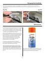
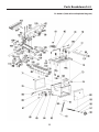
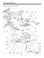
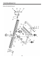
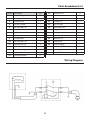
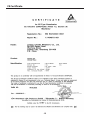
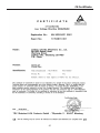
1
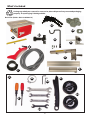
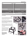
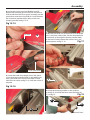
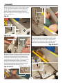
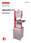
Code 508310
Code 508312
AXMINSTER
Hobby
SERIES
Product Kits
TS-200-2 & TS-250M-2
Basic Table Saws
Whole assembly instructions including leg
stand extension table and sliding table kits
Leg Stand
501248 - TS-200-2
508213 - TS-250M-2
Sliding Table Kit
501254 - TS-200-2
508214 - TS-250M-2
TS-200-2
Code: 508310
R/H Extension Table
508311 - TS-200-2
508313 - TS250M-2
Table Saw Complete Kit
717666 - TS-200-2
717667 - TS- 250M-2
TS-250-2
Code: 508312
AT&M: 24/02/2015
REF: 508472
Index of Contents
Index of Contents
02
Declaration of Conformity
02
What’s Included
03-04
Optional Accessories
05-06
General Instructions for 230V Machines
07-08
Specific Instructions/Precaution for the Saw Table
08
Specification09
Assembly09-10-11-12-13-14-15-16-17-18-19-20-21
Illustration and Parts Description
22-23-24-25
Setup and Adjustments
26-27-28
Operating Instructions
29-30
Changing the Saw Blade
30-31
Parts Breakdow/List
32-33-34-35-36-37-38-39
Wiring Diagram
39
CE Certificates
40-41
Notes42-43
Declaration of Conformity
Copied from CE Certificate
Manufactured by Laizhou Chunlin Machinery Co., Ltd.
is in compliance with the standards determined in
the following Council Directive.
The undersigned, Dipl. - Ing.
2006/42/EC Article 12, Section 3b
Authorised by Laizhou Chunlin Machinery Co., Ltd
No. 269 Baoshi Road Wenfeng Street Laizhou City,
Shandong 261400 P.R. China.
Model Number: MJ10-SB200 / MJ10-SB250
Circular Saw
Warning
Fully read manual
and safety instructions
before use
Ear protection
should be worn
The symbols below advise that you follow
the correct safety procedures when using
this machine.
Eye protection
should be worn
2
Dust mask
should be worn
HAZARD
Motor gets hot
What’s Included
Quantity
Item Part
Basic Table Saw Assembly
1 No
Basic Table Saw and Kerf Plate with Phillips Screws
A
1 No
Riving Knife
A1
12 No
Table Insert Height Shims
A2
1 No
Micro Adjuster ( TS-250M-2 ONLY)
A3
1 No
Hose Support Bracket and fixing Cap head Screws/nuts A4
1 No
Crown Guard with Flexible Hose
B
1 No
Dust Extraction Moulding
with four Phillips Screws
C
1 No
Mitre Fence Assembly
D
1 No
(Short) Rip Fence Assembly & Extension
E
1 No
(Short) Fence Rail with Scale
F
1 No
Bag Containing
G
2 No
Screwdrivers
G1
1No
Hose Clip
G2
2 No
10-12mm Spanners
1 No
13-15mm Spanner
G3
1 No
17-19mm Spanner
1 No
3mm and 4mm Hex Keys
G4
1 No
Push Stick
G5
2 No
Operating Wheel Handles
G6
Model Number
MJ10-SB200 / MJ10-SB250
(TS-200-2 Kit Code: 508310)
(TS-250M-2 Kit Code: 508312)
Optional Leg Stand Assembly
Leg A” Frames
H
Long Struts
I
Short Struts
J
Rubber Feet
K
Bag Containing
L
M8x16mm Coach Bolts with Nuts
L1
M8x16mm Bolts with Large Washer and Nut
L2
(TS-200-2 Kit Code: 501248)
(TS-250M-2 Kit Code: 508213)
Optional R/H Extension Table Assembly
1 No
(Long) Rip Front Fence Rail with Scale
M
1 No
(Long) Rip Fence Assembly
N
1 No
(Long) Rear Rip Fence Guide Rail
O
1 No
Extension Table
P
1 No
Extension Table Support Leg
Q
10 No
Cap head Screws
Q1
13 No
Washers
Q2
3 No
Nuts
Q3
(TS-200-2 Kit Code: 508311)
(TS-250M-2 Kit Code: 508313)
Optional Sliding Table Assembly Angle Fence R
Angle Fence End Block with two Phillips screws
R1
Work Clamp Assembly
S
Flip Over Stop
T
Work Clamp and Connecting Blocks
U
Sliding Carriage Support Arms
V
Bag Containing
W
M6x35mm Bolt and nut
W1
M6x45mm Countersunk Head and Washer/Nut
W2
M6x16mm Bolt and Washer/Nut
W3
M8x10mm Bolt and Domed Nut (Carriage Arm Stop)
W4
Carriage Arm
X
Sliding Carriage Table
Y
( TS-200-2 Kit Code: 501254)
(TS-250M-2 Kit Code: 508214)
4 No
4 No
4No
4 No
1 No
32 No
4 No
1 No
1 No
1 No
1 No
1 No
2 No
1 No
4 No
4 No
4 No
2 No
1 No
1 No
3
What’s Included
Having unpacked your saw and its accessories please dispose of any unwanted packaging
properly. The packaging is biodegradable.
Basic Saw (Codes: 508310 & 508312)
A1
A2
A3
A
A4
D
B
E
F
C
G
G2
G4
G5
G6
G1
G3
4
Optional Accessories
Leg Stand (Kit Codes: 501248 & 508213)
K
H
I
L
J
L1
L2
R/H Extension Table (Kit code: 508311 & 508313)
M
N
O
Q1
Q3
Q2
P
Q
5
Optional Accessories
Sliding Table (Kit code: 501254 & 508214)
R
Work clamp block
S
T
U
W
W1
Connecting block
V
W2
W3
W4
X
Y
6
R1
General Instructions for 230V Machines
not use any solvents or cleaners, as these may cause
damage to any plastic parts or to the electrical
components. Keep the work area as uncluttered as is
practical, this includes personnel as well as material.
Good Working Practices/Safety
The following suggestions will enable you to observe
good working practices, keep yourself and fellow
workers safe and maintain your tools and equipment
in good working order.
Under no circumstances
should CHILDREN be allowed
in work areas.
WARNING! KEEP TOOLS AND
EQUIPMENT OUT OF THE
REACH OF YOUNG CHILDREN
It is good practice to leave the machine unplugged
until work is about to commence, also make sure
to unplug the machine when it is not in use or
unattended. Always disconnect by pulling on the
plug body and not the cable. Once you are ready to
commence work, remove all tools used in the setting
operations (if any) and place safely out of the way.
Re-connect the machine.
Primary Precautions
These machine are supplied with a moulded 13
Amp. Plug and 3 core power cable. Before using the
machine inspect the cable and the plug to make sure
that neither are damaged. If any damage is visible
have the tool inspected/repaired by a suitably
qualified person. If it is necessary to replace the plug,
it is preferable to use an ‘unbreakable’ type that will
resist damage on site. Only use a 13 Amp plug and
make sure the cable clamp is tightened securely. Fuse
as required. If extension leads are to be used, carry
out the same safety checks on them and ensure that
they are correctly rated to safely supply the current
that is required for your machine.
Carry out a final “tightness” check e.g. guide fence,
table tilt, etc., check that the ‘cutting path’ (in this
case the path that the work piece will travel) is
unobstructed.
Make sure you are comfortable before you start
work; balanced, not reaching etc.
If the work you are carrying out is liable to
generate flying grit, dust or chips wear the
appropriate safety clothing, goggles, gloves, masks
etc. If the work operation appears to be excessively
noisy, wear ear-defenders. If you wear your hair in a
long style, wearing a cap, safety helmet, hair net, even
a sweatband, will minimise the possibility of your hair
being caught up in the rotating parts of the tool.
Likewise, consideration should be given to the
removal of rings and wristwatches, if these are liable
to be a ‘snag’ hazard. Consideration should also be
given to nonslip footwear, etc.
Work Place/Environment
Make sure when the machine is placed that it
sits firmly on the floor, that it does not rock and is
sufficiently clear of adjacent obstacles so that cutting
operations will not be impeded. Check you have
adequate clearance both in front of and behind the
machine when cutting long stuff. If you are liable to
be processing unwieldy or awkward work pieces, it is
suggested that you consider fastening the machine
down to the floor.
The machine is not designed for sub-aqua operation,
do not use when or where it is liable to get wet. If the
machine is set up in the open, and it starts to rain
(unusual though this would be in U.K.), cover it up or
move it into the dry. If the machine has got wet; dry
it off as soon as possible with a cloth or paper towel.
Do not use 230V a.c. powered machines anywhere
within a site area that is flooded or puddled and do
not trail extension cables across wet areas. Keep the
machines clean; it will enable you to more easily see
any damage that may have occurred. Clean the
machine with a damp soapy cloth if needs be, do
Do not work with cutting tools of any description
if you are tired, your attention is wandering or you
are being subjected to distraction. A deep cut, a lost
fingertip or worse; is not worth it!
Do not use this machine within the designated safety
areas of flammable liquid stores or in areas where
there may be volatile gases. There are very expensive,
very specialised machines for working in these areas,
THIS IS NOT ONE OF THEM.
7
General Instructions for 230V Machines
Above all, OBSERVE…. make sure you know what is
happening around you and USE YOUR COMMON
SENSE.
Check that blades are the correct type and size, are
undamaged and are kept clean and sharp, this will
maintain their operating performance and lessen the
loading on the machine.
Specific Instructions/Precaution for the Saw Table
Make sure the saw blade is the correct type for the
job in hand. Do not force the saw, if the saw begins
to ‘stall’ you are ‘forcing the cut’ or over working the
saw.
the blade. Leave the machine disconnected from the
mains supply until you are about to commence work.
Always disconnect the machine if you are leaving it
unattended.
Ensure that the saw blade is clean and sharp.
Never leave the vicinity of the machine
unless the blade has come to a complete stop.
Resin build up on the blades will increase the friction
of the saw passing through the timber, and cause
over heating of the blade, blunt teeth will work
harder tearing the fibre of the timber as opposed to
shearing it, also with subsequent overheating. Both
faults unnecessarily load the machine beyond
normal usage, and shorten its longevity.
Do not attempt to carry out any maintenance,
corrective work, setting up etc., unless the machine
is disconnected from the mains supply. If any tools
have been used during setting up procedures, make
sure they are removed from the machine and stowed
safely away.
Do not use blades that are deformed in any way.
Do not attempt to carry out cross cutting operations
‘freehand’, always use the mitre fence for small
stuff and the sliding carriage for larger work pieces.
Unless you are an experienced machine operator, do
not attempt to ‘rip’ freehand, always use the guiding
facility of the rip fence.
Do not remove the blade guard. The design of the
riving knife on the machine will not allow for slotting
or ‘blind’ grooving, so there is no reason to remove
the guard.
Do not remove the riving knife.
It is perfectly acceptable to support guide and feed
the timber with your hands whilst ripping stuff of
some length, however, as you approach the blade
ensure that the push stick is to hand, and you use it.
Do not use any blades that cut a smaller kerf than
the riving knife thickness. Make sure the riving knife
is correctly adjusted to the blade and is securely
fastened. If the table insert becomes damaged or
broken, and will not support the timber ‘up close’ to
the blade, replace it.
Remember the emphasis of the ‘push’ should be
between the blade and the fence and close to the
fence. Use your free hand to support and guide the
material on the offside of the saw blade and at least
100mm away from it. If the timber does not extend
to at least 100mm to the offside of the saw blade,
the material possibly does not need guiding or
supporting.
Do not start the saw with the work piece touching
the blade.
Do not commence sawing until the blade
has run up to full speed.
Check (especially on site), that there are no foreign
objects e.g. old nails, screws, small stones etc
embedded in the material you are about to cut. If
necessary take a wire brush to the timber before
working.
After switching off, never try to slow the saw down
more quickly by applying side pressure (with a piece
of wood?) to the blade. Apply the old joiner’s adage
of never getting hands within one handbreadth of
8
Specification
Code508310
Model
TS-200-2 Basic
RatingHobby
Power
1.1kW 230V, 1ph
Blade Dia/Bore
205mm/30mm
Blade Tilt
0° to 45°
Max Depth of Cut @ 45˚
40mm
Max Depth of Cut @ 90˚
60mm
Max Width of Cut with Fence
190mm standard, 750mm with R/H Table Kit
Table Size
675 x 400mm
Table Height
320mm
Dust Extraction Outlet
100mm
Min Extraction Airflow Required
500m³/hr
Overall L x W x H
800 x 400 x470mm
Weight55kg
Code508312
Model
TS-250M-2 Basic
RatingHobby
Power
1.5kW 230V 1ph
Blade Dia/Bore
250mm/30mm
Blade Tilt
0° to 45°
Max Depth of Cut @ 45˚
60mm
Max Depth of Cut @ 90˚
80mm
Max Width of Cut with Fence
200mm standard 760mm with R/H Table Kit
Table Size
670 x 430mm
Table Height
360mm
Dust Extraction Outlet
100mm
Min Extraction Airflow Required
750m³/hr
Overall L x W x H
920 x 560 x 560mm
Weight80kg
Assembly
Stand Assembly
Fig 01
1. Locate and identify the four leg “A” frames (H),
the long struts (I) and the short struts (J) for the
stand, and the packet containing 32 M8 x 16mm
coach bolts, washers and nuts,(L1).
I
J
2. Using the M8 x 10mm coach bolts, nuts and
washers bolt together two ‘A’ frames using two
legs (H) one long strut (I) in the middle and one
short strut (J) at the top. ‘finger tighten’ the nuts
only at this time, see fig 1.
L1
H
Fig 02
3. When the two ‘A’ frames have been assembled,
select one, turn it upside down on a flat surface
and loosely bolt the ‘short struts’ (J) and long struts
(I) in place, see fig 2. Attach the other “A’ frame and
loosely tighten.
J
I
4. When all the components are
assembled, turn the stand over
and place the four rubber feet
(K) to the ends of the ‘A’ frames.
(See fig 3) Upright the frame
and stand on the floor, see
fig 4.
NOTE: GO ROUND THE
FRAME AND FINGER
TIGHTEN THE NUTS AT
THIS POINT!
Fig 04
K
9
Fig 03
Assembly
Mounting the Saw Bench to the Stand
1. With
assistance,
place the Saw
Bench (A) onto
the stand. Align
the four mounting holes at
the base of the saw bench
with the four mounting
holes at each corner of
the stand. Using four M8
x 16mm hex bolts, large
washers & nuts (L2) secure
the saw bench to the
stand, see figs 05-06. Now
tighten all the nuts on the
stand assembly.
Fig B
Tilt mechanism shaft
Fig 05
A
2. Slide the mitre fence (D) into one of the tables ‘T’
slots, see fig 08.
3. Remove the table inset, place safely aside and
raise the saw blade to its maximum height,
see fig 09.
Fig 08-09
L2
D
2. Locate the yellow kerf plate and four Phillips
screws and secure it into the tables recess, see fig 7.
Fig 07
Table insert
4. Locate the riving knife (A1). Loosen the two nuts
holding the riving knife clamping plates, slide the
riving knife down between the two plates and lightly
tighten to hold the riving knife in place. Check that
the tip of the knife has a clearance of 3-8mm
between the blade then tighten the nuts to secure
the riving knife in place, see figs 10-11-12.
Fig 10-11-12
Clamping plate
Basic Saw
A1
1. Locate the two operating wheel handles (G6) and,
using the supplied 3mm Hex key (G4), secure one to
the height mechanism shaft to the front of the saw
by undoing the grub screw on the operating wheel
handle (G6) and sliding it onto the shaft, making sure
the grub screw is in line with machined slot (a), in the
shaft. Retighten the grub screw. Repeat for the tilt
mechanism to the right hand side of the saw.
Fig A
Height mechanism shaft
G6
A1
a
3-8mm Gap between the
riving knife and the blade
10
Assembly
5. Locate the crown guard and flexible hose (B).
Remove the clamping pin bolt, washer and lift and
shift handle from the crown guard assembly, slot the
guard down over the riving knife (A1) until the holes
are in line then replace the pin bolt, washer and
clamping handle, see figs 13-14.
Fig 13-14
Pin bolt
B
7. Remove the three nuts and washer from the fence
rail (F) and place safely aside. Slot the threaded bolts
in the fence rail through the three pre-drilled holes
to the front of table, replace the washers/nuts and
lightly tighten, see fig 17-18.
Fig 17
Lift & shift handle
6. Locate the table insert height shims (A2), place
a shim over the pre-drilled holes in the table insert
recess place the insert on top and check its level
with the main table, see fig 15-16. Add extra shims if
required.
F
Fig 15-16
8. Lift up the clamping handle on the rip fence
assembly (E) and slide the fence onto the fence rail
(F), see fig 19.
Fig 19
F
E
A2
11
Continues Over...
Assembly
Rip fence extension
9. Move the fence (E) until it’s in line with the tables
‘T’ slot, see fig 20. If the fence is out of alignment
loosen the four cap head screws on top of the rip
fence assembly and adjust the fence until its in
alignment with the ‘T’ slot, re-tighten the cap head
screws, see fig 21-22.
Fig 20
‘T’ Slot
E
Fig 21-22
Cap head screws
Hex key
11. Slide the rip fence assembly (E) up against the
blade and check the index marker on the magnifying glass reads ‘zero’ on the scale. If adjustment is
required loosen the fence rail (F) and adjust until it
reads ‘zero’. Secure the fence rail, see fig 25-26-27.
Fig 25-26-27
10. Remove the two clamping handles, washer from
the fence assembly and place aside, remove the two
coach bolt and insert them to the opposite side.
Locate the rip fence extension and insert the two
coach bolts into one of the two ‘T’ slots in the fence
extension. Replace the washers and clamping
handles you removed earlier. We advise you move
the rip fence extension down until the end face is
centred with the blade, see fig 23-24-25.
Coach bolt
Index marker
Fig 23-24-25
Magnifying glass
Scale
12
Assembly
13. Lift up the fence clamping handle, push in and
turn the control knob on the micro adjuster (A3) and
check it tracks smoothly down the fence rail (F), see
fig 31.
Fig 31
Micro Adjuster (TS-250M-2 ONLY)
12. Locate the micro adjuster (A3), remove the end
cap from the rip fence assembly (E), see fig 28. Insert
the mounting blocks on the micro adjuster (A3) into
the ‘T’ slot to the side of the rip fence assembly. Line
up the drive pinion with rack and using the supplied
Phillips screwdriver secure the micro adjuster to
the underside of the fence assembly, see fig 29-30.
Replace the end cap.
NOTE: Make sure the teeth of the pinion
engages into the rack.
Control knob
14. Locate the dust extraction moulding (C). Remove
the four Phillips screws and washers around the
extraction outlet, line up the holes in the dust
extraction moulding with the threaded holes to
the side of the saw and secure in position with
the screws you removed earlier, see fig 32-33.
Fig 32-33
Fig 28-29-30
Extraction outlet
End cap
Phillips screw
‘T’ Slot
C
A3
Mounting blocks
13
Continues Over...
Assembly
15. Attach the hose support bracket (A4) to the far
corner of the saw table using two cap head screws
and nuts, see fig 34-35.
Fig 37
Fig 34-35
Cap head screws
Hex key
Fig 38
A4
16. Locate the flexible hose (B) and hose clips (G2).
Place a clip over one end of the hose and insert
the hose over the 50mm outlet on the extraction
moulding (C) and tighten the hose clip, see fig 36.
Fig 36
R/H Extension Table Kit
1. Locate the long rip fence rail (M), long rip fence
(N), long rip fence guide rail (O), extension table (P),
extension table support leg (Q), cap head screws,
(Q1), washers, (Q2) and nuts (Q3).
C
B
2. Remove the fence assembly (E), short fence rail (F)
unhook the flexible hose and remove the hose
support bracket (A4) and place safely aside.
G2
17. Place a clip over the other end of the hose and
introduce the hose over the dust outlet on the crown
guard tighten the hose clip, see fig 37. Lastly hook the
hose over the support bracket (A4), see fig 38.
3. Remove the first three nuts and washer from
the fence rail (M) and place safely aside. Slot the first
three threaded bolts in the long fence rail through
the three pre-drilled holes to the front of table and
secure with the washers/nuts and lightly tighten,
see fig 39.
14
Assembly
Fig 39
Fig 42-43
Q1
Q2
M
4. Remove the washers/nuts from the remaining
three bolts and place aside, position the bolts along
the rail, put to hand four cap head screws (Q1) and
washers (Q2), see fig 40.
5. Slot the three bolts in the fence rail (M) through
the three holes in the extension table (P), see fig 41
lift up the table (P) and align the four holes to the
side with holes in the saw table and secure using cap
head screws/washers, see fig 42-43.
6. Replace the three nuts/washers you removed
earlier from the fence rail (M) and lightly tighten, see
fig 44.
Fig 40-41
Fig 44
Q1
Q2
M
P
7. Locate six cap head screws (Q1), nine washers (Q2),
three nuts (Q3), see fig 45.
Q3
Q2
15
Fig 45
Q1
Continues Over...
Assembly
8. Locate the rear rip fence guide rail (O), line up the
holes and the machined cutouts with the ‘T’ slots to
the rear of the saw table (A), see fig 46. Insert three
cap head screws with washers through the guide rail
(O) into the threaded holes in the saw table, lightly
tighten with a Hex key. Place the further three
cap head screws with washers through the guide rail
and extension table (P), secure with the remaining
washer and nuts (Q3), see figs 47-48.
Fig 49-50
Fig 46-47-48
P
Q
O
Hex key
Machined cutout
Q2
Q1
Fig 51
10. Loosen the cap head
screw on the support leg
and lower to the floor,
Cap head screw
nip up the screw, see
fig 51.
11. Place a straight edge
across both tables and
adjust the front and rear
fence rails and support
leg until the tables are
level, see fig 52-53.
Q3
Q2
9. Locate the extension table support leg (Q), remove
the two bolts washers and nuts and place safely
aside. Line up the holes in the support leg bracket
with the two holes to the end of the extension table
(P), replace the fixing and tighten with the supplied
spanners, see fig 49-50.
16
Fig 52-53
Straight edge
Assembly
A4
12. Replace the rip fence assembly (E) onto the
front fence rail (F). Remove the short rip fence from
the main assembly by removing the four cap head
screws, place safely aside, see fig 54-55.
Fig 54-55
14. Move the fence (E) until it’s in line with the table’s
‘T’ slot, if the fence is out of alignment loosen the four
cap head screws on top of the rip fence assembly, see
fig 57 and adjust the fence until its in alignment,
re-tighten the cap head screws.
15. Remove the rip fence extension from the short
rip fence assembly and attach it to the long rip fence
(N) as described on step 10 on page 12.
16. Slide the rip fence assembly (E) up against
the blade and check the index marker on the
magnifying glass reads ‘zero’ on the scale. If
adjustment is required loosen the fixings only on
the front fence rail and lightly tap the end of the
rail until the marker reads ‘zero’ on the scale.
ONLY LIGHTLY LOOSEN THE
FRONT FENCE RAIL THEN TAP
THE END UNTIL THE MARKER
READS ‘ZERO’ ON THE SCALE.
13. Locate the long rip fence
Cap head screws
(N), insert the guide bearing
into the rear guide rail (O), see fig 56 align the four
holes to the opposite end with the holes in the main
clamping assembly and replace the cap head screws,
securely tighten with the Hex key, see fig 57.
NOTE: PLACE A STRAIGHT EDGE
ACROSS THE FRONT EDGE OF THE
TABLES AND CHECK THEY ARE
STILL LEVEL AND ADJUST UNTIL
CORRECT.
Fig 56-57
O
N
Guide bearing
17. Replace hose support bracket (A4) to the far
corner of the extension table and hook the flexible
hose over he bracket, see fig 57.
Sliding Table Kit
1. Position one carriage support arm (V) to the
underside of the cast iron saw bench (A), line up
the clearance holes (a) in the support arm with the
pre-drilled holes in the table, using four M6 x 45mm
countersink heads and nuts, (W2) secure the support
arm to the table using a 4mm Hex key (G4), see figs
58-59-60. Repeat for the remaining arm.
17
Continues Over...
Assembly
Fig 58
Fig 61
V
a
Fig 59-60
Threaded nuts
w3
W2
Fig 62
V
Pre-drilled holes
w1
V
Fig 63
X
2. Place an M6x16mm Hex bolt (W3) in each of the
four clearance holes on both support arms (V) and
loosely screw on an M6 nut and washer, see fig 61.
‘T’ Slot
w3
3. Locate the four M6x30mm Hex Bolts (W1) and
lightly screw each bolt into the threaded holes to
the underside of the carriage arm (X), see fig 62.
NOTE: Only screw on the bolts just enough so they
are just below the surface of the threaded nut, see
fig 11.
4. Line up the Hex bolts (W3) with the ‘T’ slots in the
carriage arm (X) and slide on the carriage arm, see
fig 63.
5. Locate the sliding carriage table (Y) and slide it
onto the carriage arm (X), see fig 64.
18
MAKE SURE THE WHEELS ON
THE CARRIAGE TABLE ENGAGE
CORRECTLY ONTO THE CARRIAGE
ARM RAILS, SEE FIG 65.
Assembly
Fig 64-65
Fig 67
Y
W4
Angle Fence
1). Put to hand the work clamp block (U), and slide it
into the T-slot on the angle fence (R). Locate the
connecting block (U) and slide it onto the angle fence
as before, see figs 68-69. Slide the T-bolt on the base
of the connecting block (U) into the T-slot on the
sliding carriage table (Y), see figs 70-71. Locate the
plastic block and Phillips screws (R1), secure it to the
end of the angle fence (R), see fig 72.
Carriage arm rail
Fig 68-69
6. Slide the carriage table (Y) to one end of the saw
table (A), place a Level across both tables and adjust
the M6 Hex bolts (W1) until the sliding carriage table
(Y) is level with the table saw table (A), see fig 66.
Repeat for the opposite side. When both tables are
level tighten the four M6 Hex nuts (W3) to secure the
sliding arm (X) in position.
Work clamp block
U
Fig 66
R
‘T’ Bolt
U
Connecting block
7. Locate the two carriage arm stops (W4), loosen the
domed nuts and slide the bolt heads into each end of
the carriage arms ‘T’ slot. Tighten the nuts to lock the
stop in place, see fig 67.
19
Continues Over...
Assembly
Fig 70-71
Fig 73-74
‘T’ Slot
Y
S
U
Lift and shift handle
Connecting block
Lift and shift handle
Angle fence stop
‘T’ Bolt
Fig 72
Fig 75
R1
The picture above shows the angle fence (R)
removed from the carriage table for clarity.
2. Locate the work clamp (S), slot the work clamp into
the 20mm hole in the work clamp block (U),
secure in position with the lift and shift handle, see
fig 73. To set the angle fence at 90˚, push the angle
fence (R) up against the stop, see fig 74.
3. Make sure the plastic block on the end is just
missing the blade. Using a 90˚ square check that
the blade is at 90˚ to the angle fence (R), see fig 75.
90˚ Square
When correct tighten the lift and shift handle on the
connecting block (U), see fig 71. If the angle fence (R)
is not set to 90˚, undo the grub screw to the side of
the sliding carriage table (Y), using a flat screwdriver
turn the eccentric bush until the angle is correct, see
figs 76-77.
4.To set the angle fence (R) to angles between 45˚
and 90˚ loosen the three lift and shift handles on
the connecting and work clamp blocks (U) and set
the fence to the required angle on the scale on the
20
Assembly
Fig 76-77
Fig 80
T
Grub locking screw
R
5. Locate the flip over stop (T) and slide it into the
T-slot on top of the angle fence (R), see fig 80. Tighten
the butterfly knob.
Eccentric bush
carriage table (Y), see figs 78-79. Tighten the three lift
& shift handles to lock the angle fence in position.
Note: The fence can also be used at the rear of the
sliding carriage table if you prefer to push the
timber against the fence.
TS-200-2
Fig 78-79
Carriage table scale
TS-250M-2
21
Illustration and Parts Description
Rip fence extension
Work clamp block
Flexible hose
Crown guard
Sliding table assembly
Hose support bracket
Connecting block
R/H extension table
Basic table saw
Tilt operating wheel
Stand
TS-200-2 Complete Kit
Crown guard clamp
Flip over stop
Work clamp
Sliding carriage table
Rip Fence assembly
Rear guide rail
Carriage arm
Mitre fence
Front fence rail
Rip fence extension
clamping handles
TS-250M-2 Complete Kit
Rise & fall operating wheel
22
Extension table support leg
Illustration and Parts Description
TS-200-2 Basic Saw
TS-250M-2 Basic Saw
23
Illustration and Parts Description
Clamping knob
Shroud
OFF
ON
Scale
Pointer
Mitre fence assembly
NVR ON/OFF switch with emergency stop shroud
Adjusting screw
Pointer
Scale
Tilt operating wheel
Tilt scale pointer and adjusting screw
Tilt mechanisum clamp
Scale
Rise and fall operating wheel and the
clamping handle for the tilt mechanisum
Carriage table scale for measuring set angles
24
Illustration and Parts Description
Clamp
A
B
Work clamp block (A) and connecting block (B)
Flip over stop assembly
Scale
A
C
Fence rail scale
B
Crown guard (A), Blade (B)
and Riving knife (C)
Saw blade assembly set at 45˚
B
A
C
Rip fence clamp (A), Rip fence extension (B)
and micro adjuster (TS-250M-2 Only) (C)
25
100mm Dust extraction outlet
Setup and Adjustment
The Riving Knife
Adjusting the Rip Fence to the Blade
1. Raise the saw blade to its highest point and
remove the saw blade crown guard, see fig 13-14 on
page 11.
The fence assembly must be parallel to the saw
blade for producing accurate cuts.
2. Remove the four Hex screws and place carefully
aside, remove the table insert, see fig 81. Using the
spanner provided loosen the riving knife and check
that the tip of the knife has a clearance of 3-8mm
between the blade then tighten the nuts to secure
the riving knife in place, see fig 82.
NOTE: Check that the riving knife is parallel to the
saw blade by placing the fence up against them.
(See fig 83).
1. Remove the crown guard, raise the fence clamping
handle and slide the fence assembly up against the
saw blade and check it reads “ZERO” on the fence rail,
see fig 84.
NOTE: If adjustment is required loosen the fixings
ONLY on the front fence rail and lightly tap the
end of the rail until the marker reads ‘zero’ on the
scale. Check the tables are still level by placing a
stright edge across the front edge and
adjust until correct.
Fig 84
Fig 81
ZERO marker
Table insert
Riving knife
3-8
mm
Fig 82-83
NOTE: Use the ‘T’ slot to the right side of the saw
blade as a reference to check the fence is parallel,
see figs 85-86. Regularly check the fence is
parallel to ensure a perfect cut.
Fig 85-86
Fence
Tables ‘T’ slot
26
Setup and Adjustment
4. The rip fence extension can be repositioned from
the vertical to a horizontal position for guiding thin
timber pieces through. Loosen the two clamping
handles holding the fence extension, remove, lay
the fence extension down in the horizonal position
and remount the fence extension as before,see fig
87. Move the extension down until the end face is
centred with the blade and tighten the two clamping
handles to lock the assembly, see fig 88.
Adjusting the Pivot
NOTE: Before pivoting the blade for angle cuts
first remove the ‘yellow kerf plate’ from the table,
see fig 90.
Fig 90
Fig 87-88
1. Release the locking handle (A), see fig 89-91 the
saw can be angled up to a maximum of 45˚ by
turning the hand wheel (G6), see figs 91-92.
Fig 91
A
G6
Adjusting the Cutting Height
Fig 92
Adjust the blade height with the operating wheel
(G6), see fig 89, so that the blade teeth are protruding
through the work piece.
Fig 89
Lock
G6
G6
27
Setup and Adjustment
Setting the Blade Alignment
If the blade is not cutting 100% true, the blade is out
of alignment. Follow the instructions below on how
to set the blade to the table.
1. Remove the blade crown guard and table insert,
see fig 93.
2. Loosen the four Hex screws (A), see figs 93-94.
4. Place the rule to the opposite end of the blade
and take a further reading, see fig 96.
6. If there is any deviation between the
measurements,adjust the blade assembly by
moving each end on its rails (B) (beneath the table),
see figs 97-98, until both ends of the blade are the
same distance away from the ‘T’ slot edge.
7. Tighten the four Hex scews (A).
3. Place a steel rule up-against one end of the blade
and take a measurement to the ‘T’ slots edge, see fig
95.
8. Replace the blade guard and table insert.
Fig 96
Fig 93-94
A
A
Table insert
Fig 97-98
Blade rail
Blade assembly
A
Fig 95
B
Steel rule
Table ‘T’ slot
28
Operating Instructions
Fig 99
NOTE: BEFORE USING YOUR
SAW, GO ROUND AND MAKE
SURE EVERYTHING IS SECURE,
FASTENED DOWN, THAT ALL
TOOLS ARE CLEARED AWAY
FROM THE WORK AREA!
CHECK: THE BLADE FOR
SHARPNESS,MISSING TEETH,
RESIN BUILD UP ECT., CLEAN
IF NECESSARY. CHECK THE
BLADE IS SECURELY CLAMPED
IN PLACE (I.E. NOT LOOSE)!
Fig 100
CONNECT THE SAW TO THE
MAINS SUPPLY!
Give the machine a ‘quick’ burst check ( i.e. quick
ON-OFF) to ensure everything is O.K. If everything is
satisfactory, the table saw is ready for use.
WARNING! KEEP TOOLS AND
EQUIPMENT OUT OF THE
REACH OF YOUNG CHILDREN!
UNDER NO CIRCUMSTANCES
SHOULD CHILDREN BE ALLOWED
IN THE WORK AREAS!
Feeding the Work by Hand
CONNECT A DUST EXTRACTON
MACHINE TO THE DUST
EXTRACTION OUTLET ON YOUR
TABLE SAW!
NOTE: Secure larger pieces of timber to the table
by using the clamp assembly (S), see fig 73.
Cutting Narrow Pieces
Use the small flat surface of the fence to cut thin
timber narrower that 120mm, see fig 87-88. Use a
push stick.
The Mitre Fence
The mitre fence (D) can be mounted on either side
of the saw blade in the two ‘T’ slots, pre machined
into the saw table, see fig 101. The mitre fence can be
angled from 90˚ to 45˚ degrees, see fig 102-103.
Fig 101
‘T’ Slot
Start up the saw, wait until it has reached full speed
and slowly feed the timber through using both
handles, (making sure to keep your hands well clear
of the blade and using a push stick for small pieces),
until the timber is behind the riving knife. Switch off
the saw, wait until the blade has come to a complete
stop and remove the timber, see figs 99-100.
D
29
Operating Instructions
Fig 102
Fig 103
THE BLADE IS SET
AT AN ANGLE
LESS THAN 90˚
DEGREES FOR
BEVEL CUTS
HOLD THE
WORK FIRMLY
LOCK THE MITRE
FENCE AND HOLD
THE WORK FIRMLY
BLADE GUARD
Changing the Saw Blade
1. Raise the saw blade to its highest point, remove
the saw blade guard, remove the four Hex screws
that secure the table insert, place carefully aside
and remove the table insert, see fig 104. Using the
spanner provided, put the spanner onto the flats on
the bolt and place a piece of timber up against the
saw blade to stop it from moving, see fig 105.
Fig 105
Saw bolt
Spanner
NOTE: BE CAREFUL NOT TO DISTURB
THE SHIMS BENEATH THE TABLE
INSERT IF FITTED AS THE SHIMS ARE
SET SO THE TABLE INSERT IS LEVEL
WITH THE TABLE SURFACE!
2. Slacken off the saw bolt (remember right hand
thread). Remove the saw bolt, then remove the
sawplate washer and the saw blade, see figs 106-107.
It would be a good time to give the interior of the
machine, the dust extraction channels, etc. a
thorough clean.
Fig 104
Hex screw
Table insert height shims
3. Check the new blade for damage, missing teeth,
sharpness etc. Fit the new blade, ensure that the
teeth are pointing towards the front of the machine.
Put the sawplate washer onto the shaft and twist on
the saw bolt. Spin the bolt up finger tight and check
the saw is correctly seated.
4. Place the piece of timber against the blade as
before and tighten up the saw bolt, check the riving
knife is aligned with the saw blade, and correctly
positioned. Replace the table insert and secure with
the four Hex screws. Replace the saw blade guard.
When everything is satisfactory, turn the saw blade
once by hand to check it doesn’t foul anywhere.
5. Reconnect the machine to the mains supply. Give
the machine a ‘quick’ burst check (i.e. quick ON-OFF)
to ensure everything is O.K. If everything is
satisfactory, continue to use the machine.
30
Changing the Saw Blade
6. Check the old blade for sharpness, missing teeth, resin build up, etc., clean if necessary and send for
refurbishment/resharpening if required. If the blade is not to be re-sharpened, clean and pack away in its
storage case.
Fig 106
Fig 107
Sawplate washer
Blade
Maintenance
1. Keep the saw as clean and free from saw dust build
up as is practical. Periodically, remove the saw gullet
and vacuum out and clean out the saw box and the
extraction housing. Remove any resin build up in the
saw box, using a proprietary resin cleaner.
2. Clean the threaded drive shafts of the rise and fall
and tilt mechanisms. At the same time check the belt
drive, i.e. the belt is not ‘glazing’ with resin build up,
likewise with the pulley wheels. Check the belt
tension. If the belt is becoming slack, loosen the
motor hold down bolts and drive the motor
backward with its adjusting bolt.
3. Check the saw blade regularly for chipped,
missing, damaged teeth etc. and remove any resin
build up from the blade, riving knife etc.
4. If you have finished using the saw bench, clean
above and below the work table wipe the saw bench
over. If the saw bench is not going to be used for a
period of time, smear a light coat of suitable oil over
the work table and place a dust sheet over the saw
bench.
Every three or four months we recommend you use
‘Ambersil Dry PTFE Film Antistick’ spray to lubricate
the blade and tilt, rise and fall screw threads.
31
Parts Breakdown/List
TS-200-2 and TS-250M-2 (Motor Housing Exploded Diagram)
32
Parts Breakdown/List
Qty
36
Ball bearing
1
1
Set screw
1
37
C-Spring
1
2
Shaft
1
38
Shaft
1
3
Hand wheel
1
41
Supporting plate
1
4
Pin
1
42
Washer
2
5
Sharp
1
43
Nut
2
6
Pin
1
44
Washer
1
7
Lead screw nut
1
45
Nut
2
8
Motor
1
46
Washer
1
9
C-Spring
1
47
Lever
2
10
Motor guidance plate
1
48
Sawing base
1
11
Arbor
1
49
Pin
1
12
Washer
3
50
Screw
1
13
Set Screw
3
51
Washer
1
14
Set Screw
2
52
Connecting plate
1
15
Washer
1
53
Lock bolt M5
1
16
Long plate
1
54
Screw
1
17
Washer
1
55
Screw
1
18
Nut
2
56
Hand wheel
1
19
Motor pulley
1
57
Screw
2
20
Extractor connecting piece
1
58
Nut
1
21
Washer
1
59
Thread shaft
1
22
Set screw
1
60
Plate
1
23
Blade
1
61
Clamp
2
24
Flange
1
62
Dust extraction hose
1
25
Washer
1
63
Base
1
26
Set screw
1
64
Switch box
1
27
Washer
2
65
Switch
1
28
Set Screw
2
66
Clamp for cord
1
29
Holding plate A
1
67
Set screw
4
30
Riving knife
1
68
Power Cord
1
31
Holding plate B
1
69
Washer
1
32
Poly-V belt
1
70
Arbor
1
33
Spindle pulley
1
71
Plate
2
34
Washer
2
72
Supporting rear
2
35
Ball bearing
1
73
Washer
2
Part No
Description
33
Parts Breakdown/List
74
Nut
1
107
Lens
1
75
Table
1
108
Taping screw ST4.2×12
8
76
Cover
1
109
End cap,fence carrier
2
77
Screw
6
110
Fence carrier
1
78
Screw
4
111
Eccentric shaft
1
79
Pin
1
112
Lock plate
36
80
Scale
1
113
Pan head screw M4×10
1
81
Lock handle
1
114
Hex nut M8
1
82
Screw
1
115
Lock handle,fence
2
83
Bung
1
116
T-nut M5
8
84
Hex nut
1
117
Pan head screw M5×10
2
85
Flat washer
1
118
Fine adjusting handle
1
86
Bearing Bar
1
119
Coil spring,fine adjust
1
87
Bearing
2
120
Eccentric arbor
1
88
Small handgrip
1
121
Set screw M6×6
2
89
Tap screw 4 ×12
1
122
Gear rod,fine adjust
1
90
Flat head screw M4×8
6
123
Core gear
1
91
Right protection plate
1
124
Washer 4mm
1
92
Safety screen (left)
1
125
Sunk head screw M5×8
1
93
Safety screen (right)
1
126
Lock shaft,fine adjust
1
94
Left protection plate
1
127
Screw guide
2
95
Tap screw 4 ×24
2
128
Rubber sticker
2
96
Lock bolt
1
129
Frame,fine adjust gear
1
97
Washer 5
1
130
End cap,front rail
2
98
Connecting plate
1
131
screw M8×25
3
99
Flat washer 5
1
133
Rack,fence
3
100
Fence extrusion aluminium
1
134
Pan head screwM5×8
6
101
Bush bearing
4
135
Dust cover
1
102
Screw M6×65
4
136
Screw M5×12
4
103
Fence”L”shape
1
137
Support plate
1
104
Carriage crew M6×55
2
138
Screw M6×16
3
105
Fence plate
1
139
Cover
1
106
Circle ring
1
140
Front rail
1
34
Parts Breakdown/List
TS-250M-2 (Table & Fence Exploded Diagram)
35
Parts Breakdown/List
TS-200-2 (Table & Fence Exploded Diagram)
36
Parts Breakdown/List
Part No
Description
Qty
85
Flat washer
1
56
Hand wheel
1
86
Bearing Bar
1
57
Screw
2
87
Bearing
2
58
Nut
1
88
Small handgrip
1
59
Thread shaft
1
98
Connecting plate
1
60
Plate
1
99
Flat washer 5
1
61
Clamp
2
100
Fence extrusion aluminium
1
62
Dust extraction hose
1
101
Push
4
63
Base
1
102
Screw M6×65
4
64
Switch box
1
103
Fence “L”shape
1
65
Switch
1
104
Carriage screw M6×70
2
66
Clamp for cord
1
105
Screw
2
67
Set screw
4
106
Flat washer 4
1
68
Power Cord
1
107
Poiniter with magnifier
1
69
Washer
1
108
Locking handle
1
70
Arbor
1
109
Locking eccentric block
1
71
Plate
2
110
Screw M4×8
3
72
Supporting rear
2
111
Flat washer 4
1
73
Washer
2
112
Spring sheet
1
74
Nut
1
113
Pivot for locking
1
75
Table
1
114
Sliding base
1
76
Cover
1
115
Slide guide end plate
1
77
Screw
6
116
Slide guide plate
1
78
Screw
4
117
Hex bolt M6×16
4
79
Pin
1
118
Dust cover
1
80
Scale
1
119
Screw M5×12
4
81
Lock handle
1
120
Support plate
1
82
Screw ST2.9×9.5
1
121
Screw M6×16
3
83
Bung
1
122
Cover
1
84
Hex nut
1
37
Parts Breakdown/List
Sliding Table Exploded Diagram
38
Parts Breakdown/List
Qty
17
Screw M4 x 12
2
1
C-shaped ring
1
18
Wood block
1
2
Sliding axle
1
20
Angle fence
1
3
Eccentric bush
1
21
E’ ring ɸ 16
1
4
Hex thin nut M8
1
22
Press handle
1
5
Set screw M8 x 25
1
23
Square toes nut
1
6
Eccentric nut
2
24
Angle.ruler
1
7
Trolley
4
25
Sliding table
1
8
Washer ɸ 6
4
26
Locking nut M10
1
9
T-shaped bolt
1
27
Washer ɸ 10
1
Part No
Description
10
Set screw M8 x 10
1
28
Turing plate
1
11
Homocentric nut
2
29
Small handgrip
1
12
Socket countersunk screw
4
30
Washer ɸ 6
1
13
Rhombic handgrip
2
31
Locating pole
1
32
Hex bolt M6 x 35
1
14
Washer ɸ 6
3
15
Connecting block
2
Wiring Diagram
39
CE Certificate
40
CE Certificate
41
Notes
42
Notes
43
The Axminster guarantee is available on
Hobby, Trade, Industrial, Engineer, Air Tool & CNC Technology Series machines
It’s probably the most comprehensive FREE guarantee ever- buy with confidence from Axminster!
So sure are we of the quality, we cover all parts and labour free of charge for three years!
• Look for the icon and put your trust in Axminster
• No registration necessary - just keep your proof of purchase
• Optional Service Plan for Industrial Series machinery
Great value & easy-to-use,
perfect for use at home
Solid, reliable machines
designed for daily use
Top performers with class leading features and
build quality for use in busy workshops
Quality, precision machines
for the workshop or education
Small machines for the home
engineer
Compressors and tools for home or
workshop use; durable and great value
Free Three Year Guarantee on Axminster Hobby, Trade and Industrial Series
woodworking and engineering machines, Axminster Air compressors and Air
Tools, and bench top grinders - no registration necessary just proof of purchase.
We will repair or replace at our discretion and will collect only from a UK
mainland address, irrespective of the original delivery address.
The Guarantee assumes that you have bought the correct machine for the
required operation, in accordance with our guidelines; have operated and
maintained it in accordance with the instruction manual; and that all cutting
machines will be used with a blade which is sharp and serviceable at all times.
It does not cover consumable items purchased with the original product,
including original blades or abrasives.
Precision CNC machines for
industry and education
Normal wear and tear; misuse, abuse and neglect are excluded and the machine
should not have been modified in any way. Please do not attempt to service the
product without first contacting us; we are happy to guide you but failure to do
so may invalidate the guarantee.
The Guarantee is transferable from owner to owner in the first three years but
you must have original proof of purchase. Should we need to replace a machine
in the first three years the guarantee will still continue to be effective from the
original purchase date.
Full Terms and Conditions can be found at axminster.co.uk/terms
This guarantee does not affect your statutory rights.
For more information visit axminster.co.uk/3years
Please dispose of packaging for the product in a responsible manner. It is suitable for recycling.
Help to protect the environment, take the packaging to the local recycling centre and place into
the appropriate recycling bin.
Only for EU countries
Do not dispose of electric tools together with household waste material. In observance of
European Directive 2002/96/EC on waste electrical and electronic equipment and its
implementation in accordance with national law, electric tools that have reached the end of their
life must be collected separately and returned to an environmentally compatible recycling facility.
Axminster Tools & Machinery Ltd
Weycroft Avenue, Axminster, Devon EX13 5PH
axminster.co.uk