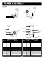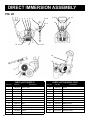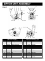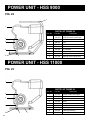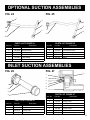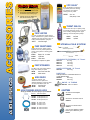
1
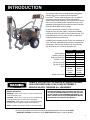
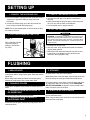
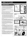
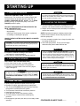
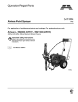
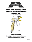
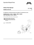
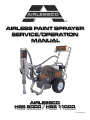
AIRLESS PAINT SPRAYER
SERVICE/OPERATION
MANUAL
AIRLESSCO
HSS 9000 / HSS 11000
001-771 DEC 08
TABLE OF CONTENTS
SECTION
Introduction........................................................................ 1
Warnings ........................................................................... 2
Setting Up.......................................................................... 5
Flushing ............................................................................. 5
How to Flush...................................................................... 6
Starting Up ........................................................................ 7
Pressure Relief Procedure ................................................ 9
Airless Spray Gun Operation ...........................................10
Airless Spray Gun Troubleshooting..................................11
Line Striping Tip Chart .....................................................12
Field Troubleshooting .......................................................13
Servicing the Fluid Pump .................................................14
Servicing the Outlet Valve Assembly ...............................15
Servicing the Inlet Valve Assembly ..................................15
Packing Replacement Procedures ...................................16
Fluid Pump Assembly.......................................................17
Manifold Filter...................................................................18
Prime Valve ......................................................................18
Hydraulic Pump and Reservoir.........................................19
Hydraulic Motor Assembly............................................... 20
Frame Assembly ..............................................................21
Direct Immersion Unit...................................................... 22
Siphon Unit...................................................................... 23
Power Unit ....................................................................... 24
Suction Assemblies ......................................................... 25
Airlessco Accessories ..................................................... 26
Airlessco
5397 N. Commerce Ave, Moorpark, CA 93021
www.airlessco.com • (805) 523-0211
2
FIGURE
1. Filling the Packing Nut/Wet Cup.................................. 5
2. Spray Gun Tip ............................................................. 6
3. Prime Valve ................................................................. 6
4. Engine Controls ........................................................... 6
5 Grounding Spray Gun ................................................. 6
6. Pressure Control ......................................................... 6
7. Gun Safety Latch ........................................................10
8. Gun Components .......................................................10
9. Spray Tip ....................................................................10
10. Spray Tip Assembly....................................................10
11. Fluid Pump..................................................................14
12. Outlet Valve ................................................................15
13. Inlet Valve ...................................................................15
14. Fluid Pump Assembly.................................................16
15. Manifold Filter .............................................................18
16. Prime Valve ................................................................18
17. Hydraulic Pump and Reservoir ...................................19
18. Hydraulic Motor ......................................................... 20
19. Frame Assembly.........................................................21
20. Direct Immersion Unit................................................ 22
21. Siphon Unit ................................................................ 23
22. Power Unit HSS9000 ................................................ 24
23. Power Unit HSS11000............................................... 24
24. Suction Assembly...................................................... 25
25. Suction Assembly...................................................... 25
26. Inlet Suction Assembly .............................................. 25
27. Inlet Suction Assembly .............................................. 25
INTRODUCTION
The Airlessco HSS series is designed with the features
painters have come to expect from the Speedflo ®
PowerTwinTM Series, while raising the bar in in hydraulic
and paint pump performance. We also substantially
enhanced the overall durabillity. The HSS series is offered
with a variety of available power options that let you take
advantage of the greater performance and value potential
inherent with the HSS series of pumps.
A careful look at these machines will show we have
designed in the very best quallity components available,
including an American made Vickers hydraulic pump. This
pump has been proven for years on heavy construction
equipment used around the world.
HSS9000 power modules mount on their own subframe for
quick "No Tools" installation and removal for transportaion
and storage. Just pivot the fan belt cover out of the way,
slip off the drive belt, and lift off the power unit.
HSS9000
HSS11000
Max Pressure
3300 PSI
3300 PSI
Output (FreeFlow)
2.70 GPM
3.30 GPM
Output (At Pressure)
2.40 GPM
3.00 GPM
Tip Size (1 Gun)
0.052 in.
0.057 in.
Tip Size (2 Guns)
0.038 in.
0.041 in.
Tip Size (3 Guns)
0.027 in.
0.031 in.
Motor
Honda
GX200
Durotech
6.5HP
Honda
GX270
Durotech
9.0HP
140 lbs
232 lbs
Weight (w/o motor)
HANDLE THIS UNIT AS YOU WOULD A LOADED FIREARM!
HIGH PRESSURE SPRAY CAN CAUSE EXTREMELY
SERIOUS INJURY. OBSERVE ALL WARNINGS!
MANUAL NOTATIONS
WARNING - Alerts user to avoid or correct conditions that
could cause bodily injury.
CAUTION - Alerts user to avoid or correct conditions that
could cause damage to or destruction of equipment.
BEFORE OPERATING THIS UNIT, READ AND FOLLOW
ALL SAFETY WARNINGS AND INSTRUCTIONS RELATED
TO THE USAGE OF THIS EQUIPMENT ON PAGES 2, 3 & 4.
READ, LEARN, AND FOLLOW THE PRESSURE RELIEF
PROCEDURE ON PAGE 9 OF THIS MANUAL.
IMPORTANT - Alerts users to steps or procedures that are
essential to proper equipment repair and maintenance.
NOTE - Identifies essential procedures or extra information.
All Service Procedures to be performed by an Authorized Airlessco Service Center ONLY.
NO MODIFICATIONS or alterations of any AIRLESSCO Equipment or part is allowed.
1
WARNINGS
MEDICAL ALERT - Airless Spray Wounds
If any fluid appears to penetrate your skin, get EMERGENCY
MEDICAL CARE AT ONCE. DO NOT TREAT AS A SIMPLE
CUT. Tell the doctor exactly what fluid was injected. Have
him read the following "NOTE TO PHYSICIAN".
NOTE TO PHYSICIAN: Injection in the skin is a traumatic
injury. It is important to treat the injury surgically as soon as
possible. DO NOT DELAY treatment to research toxicity. Toxicity is a concern with some exotic coatings injected directly
into the blood stream. Consultation with a plastic surgeon or
reconstructive hand surgeon may be advisable.
HIGH PRESSURE SPRAY CAN CAUSE EXTREMELY SERIOUS INJURY. OBSERVE ALL
WARNINGS. THIS SPRAYER IS FOR PROFESSIONAL USE ONLY.
INJECTION HAZARD
FLUIDS UNDER HIGH PRESSURE FROM SPRAY OR
LEAKS CAN PENETRATE THE SKIN AND CAUSE
EXTREMELY SERIOUS INJURY, INCLUDING THE
NEED FOR AMPUTATION.
NEVER point the spray gun towards anyone or at any part
of the body.
NEVER put hand or fingers over the spray tip. Do not use
rag or other materials over your fingers. Paint will penetrate
through material and into the hand.
NEVER try to stop or deflect leaks with your hand or body.
ALWAYS have gun tip guard in place when spraying.
ALWAYS lock gun trigger when you stop spraying.
ALWAYS remove tip from the gun to clean it.
NEVER try to "blow back" paint, it’s not an air sprayer.
ALWAYS follow the PRESSURE RELIEF PROCEDURE,
as shown on page 9, before cleaning or removing the spray
tip or servicing any system equipment.
Be sure equipment safety devices are operating properly
before each use.
ALWAYS tighten all fluid connections before each use.
MEDICAL TREATMENT
If any fluid appears to penetrate your skin, get
EMERGENCY CARE AT ONCE.
DO NOT TREAT AS A SIMPLE CUT.
• Go to an emergency room immediately.
• Tell the doctor you suspect an injection injury.
• Tell him what kind of material you were spraying with and
have him read NOTE TO PHYSICIAN above.
GENERAL PRECAUTION
2
NEVER alter equipment in any manner.
NEVER smoke while in spraying area.
NEVER spray highly flammable materials.
NEVER use around children.
NEVER allow another person to use sprayer unless he is
thoroughly instructed on its' safe use and given this
operators manual to read.
ALWAYS wear a spray mask, gloves and protective eye
wear while spraying.
ALWAYS ensure fire extinquishing equipment is readily
available and properly maintained.
NEVER LEAVE SPRAYER UNATTENDED WITH
PRESSURE IN THE SYSTEM. FOLLOW PRESSURE
RELIEF PROCEDURES ON PAGE 9.
ALWAYS INSPECT SPRAYING AREA
Keep spraying area free from obstructions.
Make sure area has good ventilation to safely remove
vapors. NEVER keep flammable material in spraying area.
NEVER spray in vicinity of open flame or other sources of
ignition. Spraying area must be at least 20 ft. away from
spray unit.
SPRAY GUN SAFETY
ALWAYS set safety lock on the gun in "LOCKED" position
when not in use and before servicing or cleaning.
DO NOT remove or modify any part of gun.
ALWAYS remove spray tip when cleaning.
Flush unit with LOWEST POSSIBLE PRESSURE.
CHECK operation of all gun safety devices before each
use. Be very careful when removing the spray tip or hose
from gun. A plugged line contains fluid under pressure. If
the tip or line is plugged, follow the PRESSURE RELIEF
PROCEDURE as outlined on page 9.TIP GUARD
TIP GUARD
ALWAYS have the tip guard in place on the spray gun
while spraying. The tip guard alerts you to the injection
hazard and helps prevent accidentally placing your fingers
or any part of your body close to the spray tip.
SPRAY TIP SAFETY
USE EXTREME CAUTION when cleaning or changing
spray tips. If the spray tip clogs while spraying, engage the
gun safety latch immediately.
ALWAYS follow the PRESSURE RELIEF PROCEDURE
before removing the spray tip to clean it.
NEVER wipe off build up around the spray tip.
ALWAYS remove tip & tip guard to clean AFTER pump
is turned off and the pressure is relieved by following the
PRESSURE RELIEF PROCEDURE.
LABELING
Keep all labels on the unit clean and readable.
Replacement labels are available from manufacturer.
WARNINGS CONTINUED ON NEXT PAGE.........
WARNINGS - CONTINUED
HOSES
Tighten all fluid connections securely before each use. High
pressure fluid can dislodge a loose coupling or allow high
pressure spray to be emitted from the coupling and result in
an injection injury or serious bodily injury.
Only use a hose that has a spring guard. The spring guard
helps protect the hose from kinks or other damage which
could result in hose rupture and cause an injection injury.
NEVER use a damaged hose, which can result in hose
failure or rupture and cause in injection injury or other
serious bodily injury or bodily damage. Before each use,
check entire hose for cuts, leaks, abrasion or bulging of
cover, or damage or movement of couplings. If any of these
conditions exist, replace the hose immediately.
NEVER use tape or any device to try to mend the hose
as it cannot contain the high pressure fluid. NEVER
ATTEMPT TO RECOUPLE THE HOSE. High pressure
hose is not recoupleable.
Help prevent damage to the hose by handling and routing
it carefully. Do not move the sprayer by pulling it with the
hose.
TOXIC FLUID HAZARD
Hazardous fluid or toxic fumes can cause serious injury or
death if splashed in eyes or on skin, inhaled or swallowed.
Know the hazards of the fluid you are using. Store &
dispose of hazardous fluids according to manufacturer,
local, state & national guidelines.
ALWAYS wear protective eyewear, gloves, clothing
and respirator as recommended by fluid manufacturer.
KEEP CLEAR OF MOVING PARTS
Keep clear of moving parts when starting or operating
the sprayer. Do not put your fingers into any openings
to avoid amputation by moving parts or burns on hot
parts.Precaution is the best insurance against an
accident.
When starting the engine, maintain a safe distance
from moving parts of the equipment.
GROUNDING
Ground the sprayer and other components in the system
to reduce the risk of static sparking, fire or explosion which
can result in serious bodily injury and property damage.
ALWAYS GROUND ALL OF THESE COMPONENTS:
1. Sprayer: Connect a ground wire and clamp (supplied) to
a true earth ground.
2. Fluid Hose: use only grounded hoses.
3. Spray gun or dispensing valve: grounding is obtained
through connection to a properly grounded fluid hose
and pump.
4. Object being sprayed: according to your local code.
5. All solvent pails used when flushing should only be
metal pails which are conductive.
Once each week, check electrical resistance of hose (when
using multiple hose assemblies, check overall resistance of
unpressurized hose must not exceed 29 megohms (max)
for any coupled length or combination of hose lengths. If
hose exceeds these limits, replace it immediately.
Never exceed 500 Ft. (150 m.) overall combined hose
length to assure electrical continuity.
PREVENT STATIC SPARKED FIRE/ EXPLOSIONS
ALWAYS be sure all equipment and objects being sprayed
are properly grounded. ALWAYS ground sprayer, paint
bucket and object being sprayed. See "grounding" above,
for detailed grounding information.
Vapors created when spraying can be ignited by sparks.
To reduce the risk of fire, always locate the sprayer at least
20 feet (6 m.) away from the spray area. DO NOT plug in
or unplug any electrical cords in the spray area, which can
create sparks, when there is any chance of igniting vapors
still in the air. Follow the coating & solvent manufacturers
safety warnings and precautions.
Use only conductive fluid hoses for airless applications. Be
sure gun is grounded through hose connections. Check
ground continuity in hose & equipment. Overall (end to
end) resistance of unpressurized hose must not exceed 29
megohms for any coupled length or combination of hose
length. Use only high pressure airless hoses with static
wire approved for 3300 psi.
Before adjusting or servicing any mechanical part
of the sprayer, follow the PRESSURE RELIEF
PROCEDURE on page 9, and remove the ignition
cable from the spark plug to prevent accidental
starting of sprayer.
WARNINGS CONTINUED ON NEXT PAGE.........
3
WARNINGS - CONTINUED
AVOID COMPONENT RUPTURE
This sprayer operates at 3300 psi (225 bar). ALWAYS be
sure that all components and accessories have a maximum
working pressure of at least 3000 psi to avoid rupture
which can result in serious bodily injury including injection
and property damage.
NEVER leave a pressurized sprayer unattended to avoid
accidental operation of it which could result in serious
bodily injury.
ALWAYS follow the PRESSURE RELIEF PROCEDURE
whenever you stop spraying and before adjusting,
removing or repairing any part of the sprayer.
NEVER alter or modify any part of the equipment to avoid
possible component rupture which could result in serious
bodily injury and property damage.
NEVER use weak or damaged or non-conductive paint
hose. Do not allow kinking or crushing of hoses or allow it
to vibrate against rough or sharp or hot surfaces. Before
each use, check hoses for damage and wear and ensure
all fluid connections are secure.
REPLACE any damaged hose. NEVER use tape or any
device to mend the hose.
NEVER attempt to stop any leakage in the line or fittings
with your hand or any part of the body. Turn off the unit
and release pressure by following PRESSURE RELIEF
PROCEDURE.
ALWAYS use approved high pressure fittings and
replacement parts.
ALWAYS ensure fire extinquishing equipment is readily
available and properly maintained.
WARNING: Do not use halogenated solvents in this system.
The prime valve, 2 gun manifold and most airless guns have
aluminum parts and may explode. Cleaning agents, coatings,
paints or adhesives may contain halogenated hydrocarbon
solvents. DON"T TAKE CHANCES! Consult your material
suppliers to be sure. Some of the most common of these
solvents are: Carbontetrachloride, Chlorobenzene, Dichloroethane, Dichloroethyl Ether, Ethylbromide, Ethylchloride,
Tethrachloethane. Alternate valves and guns are available if
you need to use these solvents.
4
FLUSHING
Reduce the risk of injection injury, static sparking or
splashing by following the specific cleaning procedure on
page 7 and 9.
ALWAYS follow the PRESSURE RELIEF PROCEDURE
on page 9.
ALWAYS remove the spray tip before flushing. Hold a
metal part of the gun firmly to the side of a metal pail and
use the lowest possible fluid pressure during flushing.
NEVER use cleaning solvents with flash points below 140
degress F. Some of these are: acetone, benzene, ether,
gasoline, naphtha. Consult your supplier to be sure.
NEVER SMOKE IN THE SPRAYING/CLEANING AREA.
GAS ENGINE PRECAUTIONS
Locate unit 25 feet away from spray area in well ventilated area. NEVER operate in closed building unless
exhaust is piped outside. NEVER allow hose to lay
against engine mufflers or hot parts. NEVER refill
fuel tank while engine is hot or is running.
IMPORTANT: United States Government safety standards
have been adopted under the Occupational Safety & Health
Act. These standards, particularly the General Standards,
Part 1910, & the Construction Standards, part 1926 should
be consulted.
WHEN SPRAYING & CLEANING WITH FLAMMABLE
PAINTS OR THINNERS:
1. When spraying with flammable liquids, the unit must be
located a minimum of 25 feet away from the spraying
area in a well ventilated area. Ventilation must be
sufficient enough to prevent the accumulation of vapors.
2. To eliminate electrostatic discharge, ground the spray
unit, paint bucket and spraying object. Use only high
pressure airless hoses approved for 3300 psi which is
conductive.
3. Remove spray tip before cleaning gun and hose. Make
contact of gun with bucket and spray without the tip in a
well ventilated area, into the grounded steel bucket.
4. Never use high pressure in the cleaning process. USE
MINIMUM PRESSURE.
5. Do not smoke in spraying/cleaning area.
SETTING UP
1. CONNECT THE HOSE AND GUN
a. Remove the plastic cap plug from the outlet and screw a
conductive or grounded 3000 psi spray hose onto
fluid outlet.
b. Connect an airless spray gun to the other end of the
hose, but do not install the spray tip yet!
NOTE: Do not use thread sealer on swivel unions as they
are made to self seal.
2. FILL THE PACKING NUT/WET CUP
FIG. 1
Fill the Packing Nut/Wet
Cup with 5 drops of
Airlessco Throat Seal
Oil (TSO).
3. CHECK THE ENGINE OIL LEVEL
a. Unscrew the oil fill plug. The dipstick is attached to
the plug.
b. Without threading the plug into place, check to be sure
the oil is up to the top mark on the dipstick.
c. If oil is needed, refer to engine manual.
4. FILL THE FUEL TANK
WARNING
WARNING: Fuel spilled on a hot surface can cause a fire or
explosion and cause serious bodily injury and property damage. Always shut off the engine and let it cool before filling
the tank, and carefully follow steps a - c below being sure not
to spill any fuel.
a. Close the fuel shutoff valve.
b. Use only clean, fresh, well-known brands of unleaded
regular grade gasoline.
c. Remove the fuel cap and fill tank. Be sure the air vent
in the fill cap is not plugged so fuel can flow to the
carburetor, then replace the cap.
FLUSHING
1. NEW SPRAYER
Your unit was factory tested in an oil solution which was left
in the pump. Before using oil-base paint, flush with mineral
spirits only.
Before using water-base paint flush with mineral spirits,
followed by soapy water, then a clean water flush.
2. CHANGING COLORS
Flush with a compatible solvent such as mineral spirits or
water.
3. CHANGING FROM WATER-BASE TO
OIL-BASE PAINT
Flush with soapy water, then mineral spirits.
4. CHANGING FROM OIL-BASE TO
WATER-BASE PAINT
5. STORAGE
Oil-base paint: Flush with mineral spirits.
Water-base paint: Flush with water, then mineral spirits and
leave the pump, hose and gun filled with mineral spirits.
For longer storage, use mixture of mineral spirits and motor
oil (half & half). Shut off the sprayer, follow PRESSURE
RELIEF PROCEDURE on page 9 to relieve pressure and
make sure prime valve is left open.
6. START UP AFTER STORAGE
Before using water-base paint, flush with soapy water and
then a clean water flush.
When using oil-base paint, flush out the mineral spirits with
the material to be sprayed.
Flush with mineral spirits, followed by soapy water, then a
clean water flush.
5
HOW TO FLUSH
FLUSHING PROCEDURE
1. Be sure the gun safety latch is engaged and there is
no spray tip in the gun. Refer to Fig. 2. Refer to your
separate instruction manual provided with your gun on
its safety features and how to engage safety latch.
2. Pour enough clean, compatible solvent into a large,
empty metal pail to fill the pump and hoses.
3. Place the suction tube into the pail or place the pail
under the pump.
4. Turn the pressure control knob to low pressure. Refer to
Fig. 3.
5. Open the prime valve to the open - "Priming Position".
This will allow an easy start. Refer to Fig. 3.
6. Turn the engine ON/OFF switch to ON.
7. Move the choke toward the closed position as per Fig.4.
8. Move the throttle lever slightly to the left as per Fig.4.
9. Turn the fuel valve ON as per Fig. 4. Pull the start rope.
Pull the engine over against compression stroke and
then let the rope rewind slowly into the starter. Pull
firmly and rapidly to start the engine. Do NOT drop the
rope. Hold on to the handle while rewinding, or the rope
may rewind improperly and jam the assembly. If the
engine does not start, open the choke a little more. If the
engine floods, open the choke all the way and continue
cranking.
10. After the engine is warm, gradually close the choke
lever, increase the RPM of engine slightly by moving
throttle to the left. Close the prime valve. Refer to Fig. 3
11. Point the gun into the metal pail and hold a metal part of
the gun firmly against the pail Refer to fig.5
12. Disengage the gun safety latch and squeeze the gun
trigger. At the same time, slowly turn the pressure
control knob (Fig. 3) clockwise just enough to move
liquid at low pressure.
13. Allow the pump to operate until clean solvent comes
from the gun.
14. Release the trigger and engage the gun safety latch.
15. If you are going to start spraying, place the pump or
suction tube into the supply container. Release the gun
safety latch and trigger the gun into another empty,
metal container, holding a metal part of the gun firmly
against the metal pail (Fig. 5), forcing the solvent from
the pump and hose. When paint starts coming from gun,
turn pressure control knob to minimum pressure, place
prime valve in prime (open) position and engage the gun
safety latch.
16. If you are going to store the sprayer, remove the suction
tube or pump from the solvent pail force the solvent from
the pump and hose. Engage the gun safety latch and
refer to the "Storage" Procedure on page 5. Step 5.
17. Whenever you shut off the sprayer follow the
PRESSURE RELIEF PROCEDURE warning on page 9.
6
FIG. 2
FIG. 3
PRIME VALVE
CLOSED
(Pressure)
REMOVE SPRAY TIP. ENGAGE
GUN SAFETY LATCH.
OPEN
(Priming &
Pressure Relief
FIG. 4
CHOKE LEVER
FUEL VALVE
WARNING: To reduce the risk of
static sparking which can cause
fire or explosion, always hold
a metal part of the gun firmly
against the metal pail when flushing. This also reduces splashing.
Refer to figure 3
THROTTLE LEVER
FIG. 5
MAINTAIN FIRM METAL TO METAL CONTACT BETWEEN GUN AND CONTAINER
FIG. 6
HYDRAULIC PRESSURE CONTROL
ASSEMBLY
STARTING UP
1. LEARN THE CONTROLS
PRESSURE CONTROL KNOB - used to adjust
pressure only. Turn clockwise to increase pressure and
counterclockwise to decrease pressure. (See Fig. 6)
PRIME & PRESSURE RELIEF VALVE - Turn to OPEN
position (see Fig. 3) to prime the pump. Turn to the
CLOSED position to spray.
FOLLOW "PRESSURE RELIEF PROCEDURES" ON
PAGE 9 WHENEVER YOU:
- are instructed to relieve pressure
- stop spraying
- checking or servicing any of the system equipment.
- or installing or cleaning the spray tip.
HANDLE SPRAY SYSTEM AS YOU WOULD A LOADED
FIREARM!
CAUTION: Do not start engine without fluid pump having
enough fluid so that it can be primed. Running fluid pump dry
will decrease life of the pumps packings.
2. PREPARE THE MATERIAL
a. Prepare the material according to the material
manufacturer's recommendations.
b. Place pump or suction tube into material container.
3. STARTING THE SPRAYER
SEE FIGURE 3 & 6 ON PREVIOUS PAGE
a. Prime Valve must be open - priming position.
b. Pressure Control Knob must be in low pressure.
c. Follow the procedure under "How to Flush", page 6,
steps 6 through 12.
WARNING
To stop the unit in an emergency or before performing
any service or maintenance procedure follow the PRESSURE RELIEF PROCEDURE on page 9 to relieve the fluid
pressure.
WARNING
If you spray into the paint bucket, always use the lowest spray
pressure and maintain firm metal to metal contact between
gun and container. See page 6, Fig 5.
5. ADJUSTING THE PRESSURE
a. Turn the Pressure Control Knob Clockwise to increase
pressure and counterclockwise to decrease pressure.
b. Always use the lowest pressure necessary to completely
atomize the material.
NOTE: Operating the sprayer at higher pressure than
needed, wastes material, causes early tip wear, and
shortens sprayer life.
c. If more coverage is needed, use a larger tip rather than
increasing the pressure.
d. Check the spray pattern. The tip size and angle
determines the pattern width and flow rate.
WARNING
Follow the "PRESSURE RELIEF PROCEDURE". To reduce
the risk of injection, never hold your hand, body, fingers or
hand in a rag in front of the spray tip when cleaning or checking for a cleared tip. Always point the gun toward the ground
or into a waste container when checking to see if the tip is
cleared or when using a self-cleaning tip.
WARNING
When you spray into the paint bucket, always use the lowest spray pressure and maintain firm metal to metal contact
between gun and container.
WARNING
To stop the unit in an emergency, turn the motor off. Then
relieve the fluid pressure in the pump and hose as instructed
in the PRESSURE RELIEF PROCEDURE.
4. PRIME THE PUMP
a. Allow pump to operate until paint comes from gun.
b. Release the trigger and engage the gun safety latch.
c. Turn Prime Valve OPEN to the prime position ensuring
the pressure is released from the system.
d. Turn Pressure Control Knob to minimum pressure.
e. Install spray tip onto gun.
f. Close the prime valve to the pressure position.
g. Turn the pressure control knob to desired spray
pressure.
h. Disengage the gun safety lock and you are ready to start
spraying.
CONTINUED ON NEXT PAGE.........
7
STARTING UP CONTINUED
6. CLEANING A CLOGGED TIP
a. Follow PRESSURE RELIEF PROCEDURE on page 9.
b. Clean the front of the tip frequently (with toothbrush only)
during the day to keep material from building up and
clogging the tip.
c. To clean and clear a tip if it clogs, refer to the separate
instruction manual received with your gun and nozzle.
IMPORTANT WARNING
Always follow the PRESSURE RELIEF PROCEDURE
on page 9 before perfoming any service or maintenance
procedure.
WARNING
Never hold your body, fingers, or hand in a rag in front of the
spray tip when cleaning or checking it for a cleared tip. Always point the gun toward the front or into a waste container
when checking to see if the tip is cleared or when using a
self-cleaning tip.
THERE IS AN EASY WAY TO KEEP THE OUTSIDE OF THE
TIP CLEAN FROM MATERIAL BUILD-UP:
Every time you stop spraying, for even a minute, lock the gun
and submerge the gun into a small bucket of thinner comparable with the material sprayed. Thinner will dissolve the build
up of paint on the outside of tip, tip guard and gun much more
effectively than if the paint dries out completely.
WARNING
Be sure to relieve pressure in the pump after filling with Airlessco Pump Conditioner.
WARNING
Clogged standard flat tip - clean only after the tip is removed from the gun. Follow the PRESSURE RELIEF
PROCEDURE Warning on Page 9.
8
7. WHEN SHUTTING OFF SPRAYER
a. Whenever you stop spraying, even for a short break,
follow the "PRESSURE RELIEF PROCEDURE ".
b. Clean the tip & gun as recommended it the spray gun
instruction manual.
c. Flush the sprayer at the end of each work day, if the
material you are spraying is water-based, or if it could
harden in the sprayer overnight. See "Flushing". Use a
compatible solvent to flush, then fill the pump and hoses
with an oil based solvent such as mineral spirits.
d. For long term shutdown or storage, refer to the
"Flushing" section of this manual.
PRESSURE RELIEF PROCEDURE
! IMPORTANT!
TO AVOID POSSIBLE SERIOUS BODY INJURY, ALWAYS FOLLOW THIS PROCEDURE WHENEVER THE
SPRAYER IS SHUT OFF, WHEN CHECKING IT, WHEN INSTALLING, CHANGING OR CLEANING TIPS,
WHENEVER YOU STOP SPRAYING, OR WHEN YOU ARE INSTRUCTED TO RELIEVE THE PRESSURE.
1. Engage the gun safety latch. Refer to the separate
instruction manual provided with your gun on its safety
features and how to engage safety latch.
2. Turn the unit off.
3. Disengage the gun safety latch and trigger the gun to
relieve residual fluid pressure.
5. Re-engage gun safety latch and close Prime/Pressure
Relief Valve.
If the SPRAY TIP OR HOSE IS CLOGGED, follow Step
1 through 5 above. Expect paint splashing into the bucket
while relieving pressure during Step 4.
If you suspect that pressure hasn't been relieved due to
damaged Prime/Pressure Relief Valve or other reason,
engage the gun safety latch and take your unit to an
authorized Airlessco Service Center.
OP
N
O SE
CL
E
HOLD METAL PART OF THE GUN IN CONTACT WITH
GROUNDED METAL PAIL. USE MINIMUM PRESSURE !
4. Turn Prime/Pressure Relief Valve to the open (priming)
position to relieve residual fluid pressure.
WARNING
NEVER leave pump unattended while under pressure!
9
AIRLESS SPRAY GUN OPERATION
SPRAY
Attach spray gun to airless unit and tighten fittings securely.
Set the gun safety latch. (Also may be called gun safety
lock, or trigger lock)
FIG. 7
GUN SAFETY LATCH
IN LOCKED POSITION
GUN SAFETY
LATCH
* The gun safety latch should always be set when the gun
is not being triggered.
Read all warnings and safety precautions supplied with the
spray gun and in product manual.
RELEASED
MAJOR COMPONENTS OF SPRAY GUN AND REVERSIBLE SPRAY TIP
FIG. 8
GUN SAFETY
LATCH OR LOCK
FIG. 9
REV-TIP™
O-RING GASKET
REV-GUARD™
REVERSIBLE
SPRAY TIP
TIP GUARD
HANDLE
(FILTER INSIDE)
METAL SEAT
TRIGGER GUARD
SPRAY TIP ASSEMBLY
CLEANING FILTER IN GUN HANDLE
1. Be sure PRESSURE RELIEF PROCEDURE is followed
before assembling tip and housing to the gun.
2. Lock gun safety latch.
3. Insert REV-TIP™ cylinder into the
REV-GUARD™ (guard housing assembly).
4. Guide metal seat into REV-GUARD™ (guard
housing assembly) through retaining nut & turn until it
seats against the cylinder.
5. Insert O-Ring gasket on metal seat so it fits in the
grooves.
6. Finger tighten REV-GUARD™ retaining nut on gun.
7. Turn guard in the desired position.
8. Completely tighten the retaining nut.
FIG. 10
RETAINING NUT
O-RING GASKET
Part # 561-026
To clean the filter, use a brush dipped in an appropriate
solvent. Change or clean filters at least once a day. Some
types of latex may require a filter change after four hours of
operation.
TO REMOVE CLOGS FROM SPRAY TIP
1. Lock gun safety latch.
2. Turn REV-TIP™ handle 180 degrees.
3. Disengage trigger lock & trigger gun into pail.
4. If the REV-TIP™ handle appears locked (resists
turning), loosen the retaining nut. The handle will now
turn easily.
5. Engage gun safety latch & return handle to the
spray position.
RETAINING NUT
REVERSE TO
UNPLUG
REV-GUARD™
GUARD HOUSING ASSEMBLY
G Thread 7/8" 561-002
F Thread 11/16" 561-001
REV-TIP™ CYLINDER
Part # 561-XXX
Spray Position Shown
METAL SEAT
Part # 561-029
CLEANING SPRAY GUN
Immediately after the work is finished, flush the gun out
with a solvent. Brush pins with solvent and oil them lightly
so they will not collect dried paint.
10
CLOGGED FLAT TIP
Should the spray tip become clogged, relieve pressure from
hose by following the PRESSURE RELIEF PROCEDURE.
Secure gun with the safety latch, take off guard, take out
the tip, soak in appropriate solvent & clean with a brush.
(Do not use a needle or sharp pointed instrument to clean
the tip. The tungsten carbide is brittle and can chip.)
AIRLESS SPRAY TROUBLESHOOTING
DEFECTS
CAUSE
CORRECTION
Coarse spray
Low pressure
Increase the pressure
Excessive fogging
(overspray)
High pressure
Material too thin
Reduce the pressure to satisfactory pattern distrabution
Use less thinner
Patten too wide
Spray angle too large
Use smaller spray angle tip
Pattern too narrow
Spray angle too small
Use larger spray angle tip (if coverage is OK, try tip in same
nozzle group)
Too much material
Nozzle too large
Material too thin
Pressure too high
Use smaller nozzle
Nozzle too small
Use next larger nozzle
Material too thick
Too little material
Reduce pressure
Thin distribution in center Worn tip
of pattern “horns”
Wrong tip
Change to new tip
Use nozzle with narrow spray angle
Thick skin on work
Material too viscous
Application too heavy
Thin cautiously
Reduce pressure and/or use tip in next smaller nozzle group
Coating fails to close &
smooth over
Material too viscous
Thin cautiously
Spray pattern irregular,
deflected
Orifice clogged
Tip damaged
Clean carefully
Replace with new tip
Craters or pock marks,
bubbles on work
Solvent balance
Use 1 to 3% “short solvents remainder “long” solvents
(this is most likely to happen with material of low viscosity,
lacquers, etc.)
Clogged screens
Extraneous material in paint
Course pigments
Poorly milled pigments
(paint pigments glocculate)
Clean screen
Use coarse screen if orifice size allows.
Use courser screen, larger orifice tips. Obtain ball milled
paint. If thinner has been added, test to see if a cover
screen. Incompatible drop placed on top of paint mixes or
flattens out on the paint mixture & thinners on the surface. If
not, try different thinner in fresh batch of paint.
Excess paint builds on
tip guard
Spray gun too close to
surface
Pressure setting too high
Hold gun further from surface sprayed
Drips, spits from tip
Valve seat and/or ball in gun
head damaged or worn
Service spray gun, replace valve assembly
Tip clogs continually
Debris in paint
Gun filter missing
Coarse filter mesh
Thouroughly strain the paint before use
Do not operate without inlet strainer
Reduce pressure setting
TEST THE PATTERN
GOOD, FULL
SPOTTY PATTERN, INCREASE PRESSURE
11
TIP SELECTION GUIDE
Spray tip selection is based on paint viscosity, paint type, &
job needs. For light viscosities (thin paints), use a smaller
tip; heavier (thicker paints), use a larger tip size. Spray tip
size is based on how many gallons of paint per minute can
SPRAY TIP - ORIFICE SIZE (INCHES)
REV-TIPTM for Painting
Fan Width (12” from surface)
in.
mm
4-6
102-152
6-8
152-203
8-10
203-254
10-12
254-305
12-14
305-356
be sprayed through the tip. Do not use a tip larger than
maximum pump flow rate or capacity the sprayer can
accommodate. Pump flow rate is measured in gallons
per minute (GPM).
.007
.009
.011
.013
.015
.017
.019
.021
.023
.025
.027
.029
.031
209
211
213
215
217
219
221
223
225
227
229
307
309
311
313
315
317
319
321
323
325
327
409
411
413
415
417
419
421
423
425
427
431
511
513
515
517
519
521
523
525
527
531
535
613
615
617
619
621
623
625
627
631
635
717
14-16
356-406
715
16-18
406-457
815
819
821
20-24
508-610
NEW WIDE TIPS:
W21
W23
Gun Filter
C=course-60 mesh
C
C
Wood Interior
Lacquer, Varnish,
•
•
•
•
•
•
•
F=Fine-100 mesh
Stain, Sealer,
Enamel
Wood Exterior
Masonry
F
F
F
•
•
•
•
•
Exterior Stain,
Vinyl, Acrylic, Latex
F,C
C
•
•
•
•
•
•
Vinyl, Oil Base, Alkyd,
Latex, Acrylic,
Block Filler,
C
•
•
•
•
Elastomer
Ceiling
Hi Build, Mil White
Structural Steel
Heaviy Coatings
Water Flow Rate
@ 2000psi, 138 bar
Paint Flow Rate
latex paint @ 2000psi,
.039
.041
335
721
C
•
•
.035
639
641
739
741, 754
831
W25
W28
W29
W31
REMOVE FILTER
•
•
•
•
•
•
•
•
•
•
•
•
•
•
•
•
•
•
•
(gpm)
(lpm)
.12
.49
.18
.69
.24
.91
.31
1.17
.38
1.47
.47
1.79
.57
2.15
.67
2.54
.77
2.96
1.03
3.90
1.31
4.98
1.63
6.17
1.80
6.81
(gpm)
(lpm)
.10
.38
.15
.57
.21
.79
.27
1.02
.33
1.25
.40
1.51
.49
1.85
.58
2.20
.66
2.50
.88
3.33
1.12
4.24
1.39
5.26
1.54
5.83
(gpm)
(lpm)
.25
1.0
.25
1.0
.33
1.25
.40
1.5
.50
1.9
.60
2.3
.75
2.8
.88
3.3
1.0
3.8
1.25
4.7
1.5
5.7
2.0
8.2
2.2
8.2
138 bar/1.36 spec. gr.
Pump Minimum
Output*
*Pump will support tip worn to next larger size.
Thickness of the paint coat per stroke is determined by
spray tip "fan width", rate of the spray gun movement, and
distance to surface. Two tips having the same tip size, but
different pattern widths will deliver the same amount of
paint over a different area (wider or narrower strip).
A spray tip with a narrow pattern width makes it easy to
spray in tight places.
During use, especially with latex paint, high pressure will
cause the orifice to grow larger. This destroys the pattern.
Replace tips before they become excessively worn. Worn
tips waste paint, cause overspray, make cutting-in difficult,
and decreases sprayer performance.
12
FINE FINISH REV-TIPTM
New double orifice design for lower pressure airless
spraying when you need finer atomization for a smoother
finish on interior trim, cabinetry, shutters, and doors
Fan Width
Inches
Orifice Size
(mm)
.012
.014
4-6
102-152
212
214
6-8
152-203
312
314
8-10
203-254
412
414
FIELD TROUBLESHOOTING
PROBLEM
CAUSE
SOLUTION
There is spitting from the gun. The fluid supply is low or empty
Air entrapped in the fluid pump or hose
• Refill the supply container.
• Check for loose connections ont he siphon
assembly, tighten, then reprime pump.
Paint leaks into the wet cup
The packing nut/wet cup is loose.
The upper packings are worn or
damaged.
Worn piston rod.
• Tighten just enough to stop leakage.
• Replace the packings. See pages 16-17.
The engine operates, but the
paint pump doesn’t cycle.
The pressure setting is too low.
The displacement pump is seized.
• Increase the pressure. See page 7.
• Service the pump. See page 14-17.
The displacement pump
operates, but paint pressure
is too low or none.
The pressure setting is too low.
The tip or gun filter is clogged.
The tip is worn.
The fluid displacement pump filter is
clogged
There is a large pressure drop in the
fluid hose.
• Increase the pressure. See page 7.
• Remove the tip and/or filter and clean them.
• Replace tip.
• Clean the filter.
The inlet valve ball is not seating
properly.
• Service the inlet valve. See page 15.
The displacement pump
operates, but the output is
too low on the downstroke or
both strokes.
• Replace piston rod.
• Use a larger diameter hose.
The displacement pump
The outlet valve ball is not seating
operates, but the output is too properly.
low on the upstroke.
The lower packings are worn or
damaged.
• Service the outlet valve. See page 15.
Engine stops.
• Refer to engine manual.
• Replace the packings. See page 16-17.
13
SERVICING THE FLUID PUMP
FLUID PUMP REMOVAL
DISASSEMBLY OF THE FLUID PUMP
REFER TO FIGURE 11
1. Follow the PRESSURE RELIEF PROCEDURE page 9.
2. Flush the material you are spraying out of the machine.
3. Remove the Front Cover.
4. Slip Retaining Ring down to expose the Piston Pin.
5. Push Piston Pin out of the piston pinhole.
6. Loosen Jam Nut until the Fluid Pump can unthread from
the Yoke.
FIG. 11
1
2
6
FLUID PUMP REINSTALLATION
5
3
4
PARTS LIST FIGURE 11
14
REFER TO FIGURE 14
1. Remove Fluid Pump from machine.
2. Remove Inlet Valve Assembly - Refer to Servicing Inlet
Valve, Page 15.
3. Remove Upper Packing Adjustment nut from Outlet
Housing.
4. Remove Pump Cylinder from Extension Tube, pulling
Displacement Rod out through bottom of Outlet Housing.
Discard O-ring.
5. Remove Outlet Housing from Extension Tube. Discard
O-ring.
6. Remove all old packings and glands from Outlet
Housing; retain Male Gland and Female Gland, they will
be re-used unless damaged.
7. Remove Piston End from Rod Extension.
8. Remove Jam Nuts from Piston End. Remove all old
packings, glands and Scraper from Piston End; retain
Male Gland and Female Gland, they will be
re-used unless damaged.
9. Disassemble Outlet Valve - Refer to Servicing Outlet
Valve, Page 15.
10. Inspect Displacement Rod and Cylinder inside surface
for wear or damage; thoroughly clean all parts to be
reused.
Item No.
Part No.
Description
1
186-100
Hydraulic Motor
2
119-099
Front Cover
3
119-025
Piston Pin
4
187-088
Jam Nut
5
116-106
Retaining Clamp
6
186-078
Yoke
REFER TO FIGURE 11
1. With the Retaining Ring loosely in place around the
pump piston, thread the Fluid Pump in to the Yoke until
the top edge of the Outlet Housing is one thread above
the inside edge of the Yoke threaded bore.
2. Tighten the Jam Nut until it stops against the bottom
edge of the Yoke.
3. Line up the Displacement Rod pin hole with the
Hydraulic Piston pin hole; insert the Piston Pin.
4. Slip the Retaining Ring up around the piston pin bore on
the Hydraulic Piston.
5. Run the machine at full pressure for several minute
and check for leaks. Release the pressure by following
the PRESSURE RELIEF PROCEDURE & readjust
the packing nut per step 7 in the Packing Replacement
Procedures on page 16.
6. Reinstall Front Cover
SERVICING OUTLET VALVE ASSEMBLY
DISASSEMBLY OF THE OUTLET VALVE
FIG. 12
REFER TO FIGURE 12
1. Remove Fluid Pump from machine - Refer to Fluid Pump
Removal, Page 14.
2. Remove Outlet Valve Assembly - Follow steps 1-9,
Disassembly of the Fluid Pump, Page 14.
3. Hold Piston End in vise bottom up to access 7/16" Hex in
Retainer. Remove Retainer.
4. Remove Outlet Seat. Do not pry, it will chip the edges.
5. Remove PTFE O-Ring, Outlet Ball and Outlet Ball
Guide.
6. Remove all old packings and glands from Outlet
Housing; retain Male Gland and Female Gland, they will
be re-used unless damaged.
7. Clean and inspect parts for wear or damage, replace
parts as necessary. PTFE O-Ring will always be
replaced in this procedure.
RE-ASSEMBLY OF THE OUTLET VALVE
REFER TO FIGURE 12
1. Install Ball Guide, Ball, Seat and O-Ring into Piston End.
2. Install Retainer into Piston End. Torque Retainer to
30 Ft-Lb.
3. Install new packings, glands and scraper - Refer to
Packing Replacement Procedures, Page 16.
1
2
3
4
5
6
PARTS LIST FIGURE 12
Item No.
Part No.
1
187-078
Piston End
Description
2
187-079
Outlet Ball Guide
3
187-091
Outlet Ball
4
106-015
O-Ring
5
187-081
Outlet Seat
6
187-082
Retainer
SERVICING INLET VALVE ASSEMBLY
DISASSEMBLY OF THE INLET VALVE
REFER TO FIGURE 13
1. Relieve pressure following PRESSURE RELIEF
PROCEDURE steps on page 9.
2. Remove Inlet Valve Housing.
3. Remove Ball Guide, O-Rings and Inlet Ball. Remove
Inlet Seat.
7. Clean and inspect parts for wear or damage, replace
parts as necessary. PTFE O-Ring and Viton O-Ring will
always be replaced in this procedure.
DISASSEMBLY OF THE INLET VALVE
REFER TO FIGURE 13
1. Reinstall inlet parts in correct order. Reverse inlet seat if
necessary.
2. Run the machine at pressure for several minutes,
inspect for leaks and proper operation.
FIG. 13
6
1
2
7
3
4
5
8
PARTS LIST FIGURE 13
Item No.
Part No.
Description
1
106-013
O-Ring, Viton
2
187-087
Inlet Ball Guide
3
106-088
O-Ring, PTFE
4
187-092
Inlet Ball
5
187-086
Inlet Seat
6
187-084
Inlet Valve Housing
7
119-110
O-Ring, Viton
8
119-092
Inlet Filter
15
PACKING REPLACEMENT PROCEDURES
DISASSEMBLY
16
REASSEMBLY
REFER TO FIGURE 14
1. Soak all Leather Packings in oil for 5-10 minutes before
assembly.
2. Install Scraper open edge downwards, and metal
Female Gland open side up on Piston End.
3. Install five UHMWPE Packings and three Leather
Packings on Piston End, open side up, in this order
from bottom: Plastic, Leather, Plastic, Leather, Plastic,
Leather, Plastic, Plastic. Finish with metal Male Gland
rounded edge downwards.
4. Install Jam Nut on Piston End: Don’t Tighten.
5. Carefully insert assembled Piston End downward
into top of Cylinder until only the metal Male Gland is
exposed.
6. Use a Packing Tool through the Piston End Outlet holes
to hold the Piston End from spinning while tightening the
Jam Nut until there are FOUR full threads exposed on
Piston End.
7. Place TWO drops of BLUE LOCTITE on the Piston End
Jam Nut threads, and install second Jam Nut. Tighten it
until it stops without moving the first Jam Nut.
8. Install metal Male Gland rounded edge upwards in the
Outlet Housing.
9. Install four UHMWPE Packings and three Leather
Packings in the Outlet Housing, open side downward
in this order: Plastic, Leather, Plastic, Leather, Plastic,
Leather, Plastic. Finish with metal Female Gland open
side downwards.
10. Install brass Packing Adjustment Nut until it contacts
Female Gland; Do Not Tighten.
REFER TO FIGURE 14
1. Intall PTFE O-Ring and Extension Tube into bottom
of Outlet Housing and tighten until the Extension Tube
stops; Do Not Over-tighten.
2. Apply BLUE LOCTITE to Piston End top threads
and install Rod Extension, tighten. Use Packing Tool
through Piston End Outlet holes to prevent Piston End
from spinning in Pump Cylinder while tightening Rod
Extension.
3. Apply BLUE LOCTITE to Rod Extension top threads and
install Displacement Rod, tighten. Use appropriate size
open end wrenches on wrench flats of Extension Rod
and Displacement Rod; Do Not place in vise or use pipe
wrenches.
4. Install PTFE O-Ring into bottom of Extension Tube.
5. Lubricate Displacement Rod with oil, and carefully insert
the Pump Cylinder/Rod/Piston Assembly through bottom
of Extension Tube/Outlet Housing Assembly, making
sure to guide the Displacement Rod Top through the
upper packings without damaging the packings.
6. Thread the Pump Cylinder into the bottom of the
Extension Tube, tighten until Pump Cylinder stops; Do
Not Over-tighten.
7. Tighten brass Packing Adjustment Nut until there is one
thread left showing.
8. Install Inlet Valve Assembly - Refer to Servicing Inlet
Valve, Page 15.
9. Reinstall Fluid Pump - Refer to Fluid Pump
Reinstallation, Page 14.
PARTS LIST FIGURE 14
PARTS LIST FIGURE 14 CONT
Item No.
Part No.
1
116-106
2
3
Description
Item No.
Part No.
Description
Retaining Ring
16
106-008**
119-025
Piston Pin
17
187-086
Inlet Seat
187-070
Displacement Rod
18
187-101+
Rod Extension
4
187-071
Packing ADJ Nut
19
187-089
Jam Nut
5
187-088
Jam Nut
20
187-079
Outlet Ball Guide
6
187-072
Female Gland
21
106-015**
O-Ring
7
187-075**
Packing UHMWPE
22
187-082
Retainer
8
187-074**
Packing Leather
23
187-087
Inlet Retainer
O-Ring
9
187-073
Male Gland
24
187-092**
Inlet Ball
10
187-076
Outlet Housing
25
106-004**
O-Ring Seal
11
187-083**
Scraper
26
187-102+
Extension Tube
12
187-078
Piston End
27
187-077
Pump Cylinder
13
187-091**
Outlet Ball
28
187-084
Inlet Valve Nut
14
187-081
Outlet Seat
29
119-110
O-Ring
15
106-012**
O-Ring
30
119-092+
Intake Filter Assy
FLUID PUMP ASSEMBLY
FIG. 14
25
1
2
18
19
3
26
9
4
8
5
7
25
6
6
8
7
11
12
27
8
20
8
13
14
9
21
22
15
23
28
10
16
24
29
17
30
17
MANIFOLD FILTER (119-084)
FIG. 15
1
PARTS LIST FIGURE 15
2
11
3
10
4
9
5
6
8
7
Item No.
Part No.
Description
1
111-202
Housing Bowl
2
301-356
Spring
3
111-204
60 Mesh Filter
4
100-005
Swivel
5
100-003
Swivel
6
111-201
Housing Base
7
100-028
Plug
8
100-129
Plug
9
169-010
Nipple
10
106-007
O-Ring, PTFE
11
111-203
Filter Support
PRIME VALVE (119-083)
FIG. 16
1
2
3
4
Item No.
Part No.
1
115-303
Handle with Label
2
117-046
Screw
8
3
115-063
Washer
4
115-072
Spacer
5
115-064
Belleville Spring (3)
6
115-065
Retaining Ring
7
115-067
Washer
8
115-071
Valve Stem
9
115-068
O-Ring Black
13
10
115-069
Ball
14
11
115-029
Valve Seat
12
115-012
Washer
13
115-073
Valve Body
14
115-074
Inlet Fitting
9
10
11
12
18
PARTS LIST FIGURE 16
5
6
7
Description
HYDRAULIC PUMP AND RESERVOIR (189-571)
FIG. 17
34
35
33
32
31
36
1
2, 3
4
5
6
7
8
9
30
29
27, 28
26
25
23, 24
22
37
38
39
41
40
10
21
19, 20
HYDRAULIC INLET
ASSEMBLY
11, 12, 13,
14, 15
18
NOTE: Hydraulic Reservoir and Hydraulic System
requires 3.5 gallons of Pennzoil A.W. Hydraulic Oil
#46. The minimum Oil Level must be approximately
halfway up the Filler Tube. Never below.
16
17
PARTS LIST FIGURE 17
Item No.
Part No.
1
189-605
2
3
Description
PARTS LIST FIGURE 17 CONT
Item No.
Part No.
Description
Pump Assy
22
189-527
Hydraulic Fitting
100-662
Set Screw
23
169-010
Nipple
189-579
Pully Assembly
24
100-005
Swivel
4
189-567
Pump Bracket
25
189-581
Hold Down Plate
5
100-173
Screw (2)
26
119-066
Ball Valve
6
100-653
Bolt
27
189-557
Fitting
7
136-235
Nut
28
119-093
Oil Filler Tube
8
106-032
Filler O-Ring
29
189-563
Oil Filter
9
189-609
Hydraulic Bypass Tube
30
189-548
Hydraulic Pressure Adjustment
10
189-569
Reservoir Top
31
119-067
Hydraulic Press Tube
11
189-556
Baffle
32
189-528
Elbow
12
189-583
Baffle Plate
33
189-564
Filler/Breath Cap
13
189-549
Baffle Stopper
34
100-227
3/4” Swivel
14
136-134
Rivet (4)
35
189-546*
Hydraulic Return Hose
15
140-042
Washer
36
136-074
Set Screw (2)
16
189-560
Pump Fitting Nut
37
189-570
Hydraulic Pump (Bare)
17
189-505
Reservoir Plug
38
189-535
Pump Inlet Tube
18
189-566
Reservoir Bottom
39
189-560
Hex Nut
19
143-021
Cap Screw (12)
40
189-565
Suction Strainer
20
113-023
Lockwasher (12)
41
189-562
O-Ring (2)
21
119-074
Reservoir Gasket
19
HYDRAULIC MOTOR ASSEMBLY
FIG. 18
1, 2
1, 6
3
5
4
PARTS LIST FIGURE 18
20
Description
PARTS LIST FIGURE 18 CONT
Item No.
Part No.
Item No.
Part No.
1
100-133
Elbow (2)
4
119-099
Front Cover
Description
2
189-545
High Pressure Hose
5
186-078
Yoke
3
186-100
Hydraulic Motor
6
189-546
Hydraulic Return Hose
FRAME ASSEMBLY
FIG. 19
6
1, 2, 3, 4
5
7
8, 9, 10, 11, 12
26
25
13
14, 15, 16, 17
24
18
23
21, 22, 16,
14, 15
19
PARTS LIST FIGURE 19
Item No.
Part No.
1
140-029
2
Description
20
PARTS LIST FIGURE 19 CONT
Item No.
Part No.
Description
Washer
14
189-576
Pivot Tube
136-217
Nylok Nut
15
100-656
Washer
3
100-377
Screw
16
140-051
Nut
4
189-558
Stop Bumper
17
100-655
Hex Bolt
5
136-233
Riv-Nut
18
301-165
Wheel
6
119-082
Bumper
19
119-079
Axle
7
189-530
Handle Assy
20
113-030
Spacer
8
189-450
Guide
21
119-080
Washer
9
189-451
Slide
22
119-081
Hex Bolt
10
331-222
Roll Pin
23
189-559
H Support Assy
11
121-024
Snap Button
24
143-029
Set Collar
12
189-452
Cover
25
189-596
Belt Cover
13
119-077
Spacer
26
189-599
Frame
21
DIRECT IMMERSION ASSEMBLY
FIG. 20
1
2
3
4
5
6
17, 18
7, 8, 9
19
10, 11
15
14, 12, 16
4, 18
20
12, 13, 14
23
22
21
PARTS LIST FIGURE 20
22
Description
PARTS LIST FIGURE 20 CONT
Item No.
Part No.
Item No.
Part No.
13
188-125
Description
1
189-554
Frame Assy
2
189-571
Hydraulic Assy
14
140-035
Flat Washer
3
189-580
Pump Shroud
15
100-390
Screw
4
189-545
Hydraulic Pressure Hose
16
100-655
Screw
5
189-548
Pressure Control
17
189-546
Hydraulic Return Hose
6
189-606
Paint Pump Assy
18
100-133
Elbow
7
100-307
Screw
19
119-083
Prime Valve
8
188-118
Nut
20
119-084
Manifold Filter
9
100-344
Flat Washer
21
136-234
Screw
10
111-014
Pressure Gauge
22
119-086
Bypass Assy
11
100-004
Elbow
23
100-170R
12
140-051
Nut
Screw
Optional Holder
SIPHON UNIT ASSEMBLY
FIG. 21
1
2
3
4
5
15, 16
3, 16
18
6, 7, 8
19
17
9, 10
11, 13, 14
11, 12, 13
20, 21, 22, 23
24
PARTS LIST FIGURE 21
Item No.
Part No.
1
189-554
2
3
Description
25
26
27, 28
PARTS LIST FIGURE 21 CONT
Item No.
Part No.
Description
Frame Assy
15
189-546
Hydraulic Return Hose
1879-571
Hydraulic Assy
16
100-133
Elbow
189-545
Hydraulic Pressure Hose
17
119-083
Prime Valve
4
119-060
Pressure Control
18
119-089
Nipple
5
189-608
Paint Pump Assy
19
119-084
Manifold Filter
6
100-307
Screw
20
120-021
Nylok Nut
7
188-118
Nut
21
331-342
Screw
8
100-344
Flat Washer
22
111-036
Spring Clip
9
111-014
Presure Gauge
23
100-170R
10
100-004
Elbow
24
119-086
Optional Holder
Bypass Assy
11
140-035
Flat Washer
25
119-087
Suction Assy
12
188-125
Screw
26
119-088
Spring Loaded Pin
13
140-051
Nut
27
136-133
Chain Ring
14
100-655
Screw
28
136-131
Grounding Chain
23
POWER UNIT - HSS 9000
FIG. 22
7
1
PARTS LIST FIGURE 22
2
3
4
5
6
Item No.
Part No.
Description
1
175-025
175-034
GX200 Honda Gas Engine
6.5HP Durotech Gas Engine
2
100-361
Set Screw
3
189-531
Pully
4
136-123
Screw
5
113-022
Nut
6
113-023
Lock Washer
7
189-593
Lifting Handle/Plate Assy
8
189-524
V-Belt (Not Shown)
9
101-434
Warning Decal (Not Shown)
POWER UNIT - HSS 11000
FIG. 23
1
PARTS LIST FIGURE 23
2
3
4
5
24
6
7
Item No.
Part No.
1
175-101
GX270 Honda Gas Engine
Description
2
100-361
Set Screw
3
189-579
Pully
4
136-123
Screw
5
113-022
Nut
6
113-023
Lock Washer
7
189-513
Plate Assy
8
189-514
V-Belt (Not Shown)
9
101-434
Warning Decal (Not Shown)
OPTIONAL SUCTION ASSEMBLIES
FIG. 24
FIG. 25
1
3
5
6
2
5
3
4
1
3
2
4
PARTS LIST FIGURE 24
Item No.
Part No.
1
189-587
2
PARTS LIST FIGURE 25
Description
Item No.
Part No.
Description
Suction Nut
1
119-107
Swivel Assy
100-668
Suction Elbow
2
100-664
1” ID Suction Hose
3
100-664
1” ID Suction Hose
3
141-008
Filter Basket
4
301-514
5 Gal Suction Tube
4
301-514
5 Gal Suction Tube
5
141-008
Filter Basket
5
250-116
Clamp
6
250-116
Clamp
INLET SUCTION ASSEMBLIES
FIG. 27
FIG. 26
7*
1
2
3
4
1
5
2
6
3
PARTS LIST FIGURE 27
4
PARTS LIST FIGURE 26
Description
Item No.
Part No.
Description
1
119-095
O-Ring, Viton
2
119-110
O-Ring, Viton
3
189-584
Swivel Nut
Item No.
Part No.
1
119-110
O-Ring
4
189-574
Swivel Body
2
189-587
Suction Nut
5
119-096
O-Ring- Viton
3
301-572
Suction Tube
6
189-573
Suction Elbow
4
119-094
Filter Basket
7
187-084*
Inlet Valve Housing
25
ACCESSORIES
AIRLESSCO
Quick Flush
STAY CLEAN™
™
Spray protectant for machine
to prevent paint from sticking
to it. Keeps your sprayer
looking new for years!
■ The only clean water flushing system
■ Cuts sprayer clean-up time in half!
■ Connects to standard garden hose
to backflush sprayer through gun
114-030
■ Includes "F" and "G" adapters to
work with all brands of gun
20 oz. can
Case quantity: 12 cans
Part # 170-005
THROAT SEAL OIL
Used in the wet cup of a piston pump
to prevent paint from drying on the piston & causing damage to the upper
packing. Use with all piston pumps.
PAINT HOPPER
For use on small jobs where paint is
kept in smaller than 5 gallon containers.
Threads onto pick-up tube of carry or
LoBoy framed Airlessco sprayers.
331-775
6 Liter Paint Hopper
PUMP CONDITIONER
188-187
188-392
XTEND-A-POLE SYSTEM
Standard Tip Extension
Should be used on piston pumps
between uses to prevent paint from
drying on the piston & causing packing wear.
010-001
010-009
010-019
Display of 48 - 1 oz. bottles
1 quart bottle
1 Gallon bottle
Case quantity: 12 on quarts, 4 on gallons
PAINT STRAINERS
Pre-filter your paint using strainer
bags. One dozen per pack.
100-064
100-065
Used to cover suction filter
5 Gallon strainer
HOSE COVER
4 mil poly protects your
airless hose from paint and
abrasion damage. Comes in 1000'
roll with perforations each 50'.
100-219
100-426
Hose Cover Roll
Case of 6 Rolls
HIGH PRESSURE AIRLESS HOSE
Strong yet flexible, for airless sprayers up to 3300 PSI
Part No:
100-012
100-040
100-204
100-199
Hose Description
3/16” Whip Hose, 4 Ft.
1/4” Whip Hose, 3 Ft.
1/4” Whip Hose, 5 Ft.
3/8” Whip Hose, 6 Ft.
100-011 1/4” Hose, 50 Ft.
100-023 3/8” Hose, 50 Ft.
100-037 1/2” Hose, 50 Ft.
100-010 1/4" Hose Connector
100-009 3/8" Hose Connector
6 oz. Bottle
1 qt. Bottle
Swivel Extension
Bare Pole
STANDARD TIP EXTENSION, “G” Thread
6” Long
12” Long
18” Long
24” Long
032-170
032-171
032-172
032-173
SWIVEL EXTENSION, “G” Thread
36” Long
032-184
BARE POLE
Add Tip Extension or Swivel Extension to
create desired length
032-053
24” Long
032-054
36” Long
SWIVEL “G” THREAD
032-035 7/8" x 14 Swivel
ADAPTERS
90° Pole to Gun Adapter
032-042
Gun Nut “F” Thread 11/16-16
032-010
Gun Nut “G” Thread 7/8-14
032-011
"F to G" Gun adapter to attach
Graco tips to Airlessco guns.
®
032-012