1
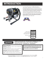
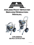
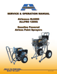
®
AIRLESS PAINT SPRAYER
SERVICE/OPERATION
MANUAL
AIRLESSCO
Model 450
001-787 Sept 08
TABLE OF CONTENTS
SECTION
Introduction........................................................................ 1
Warnings ........................................................................... 2
Flushing ............................................................................. 5
How to Flush...................................................................... 5
Setting Up.......................................................................... 6
Starting Up ........................................................................ 6
Pressure Relief Procedure ................................................ 8
Daily Maintainance ............................................................ 8
Airless Spray Gun Operation ............................................ 9
Airless Spray Gun ............................................................10
Airless Spray Gun Troubleshooting..................................11
Tip Selection Guide ..........................................................12
Electric Motor Maintenance..............................................13
Motor Brushes ..................................................................13
Field Troubleshooting .......................................................14
Optional Manifold Filter ....................................................14
Servicing the Fluid Pump .................................................15
Servicing the Outlet Valve ................................................16
Servicing the Inlet Valve...................................................16
Packing Replacement Procedures ...................................17
Gear and Pump Assembly ...............................................19
Complete Sprayer............................................................ 20
Suction Assembly.............................................................21
Pressure Control Assembly Calibration .......................... 22
Electrical System............................................................. 23
Replacement of Electrical Components .......................... 24
Troubleshooting- Machine Does Not Start ...................... 25
Airlessco Accessories ..................................................... 26
2
FIGURES
1. Spray Gun Tip .............................................................. 5
2. Pressure Control knob ................................................. 5
3. Flushing ........................................................................ 5
4. Flushing ........................................................................ 5
5 Throat Seal Oil ............................................................. 6
6. Pressure Adjustment Controls...................................... 6
7. Gun Safety Latch .......................................................... 9
8. Gun Components ......................................................... 9
9. Spray Tip ...................................................................... 9
10. Spray Tip Assembly..................................................... 9
11. Airless Spray Gun.......................................................10
12. Motor Brushes ............................................................13
13. Optional Manifold Filter...............................................14
14. Fluid Pump..................................................................15
15. Outlet Valve ................................................................16
16. Inlet Valves .................................................................16
17. V-Packings..................................................................17
18. V-Packings .................................................................18
19. Gearbox Assy .............................................................19
20. Sleeve Bearing Replacement.....................................19
21. Frame Assy................................................................ 20
22. Suction Assy ..............................................................21
23. Electrical System....................................................... 23
INTRODUCTION
Your new Airlessco 450 or ALLPRO 410E airless
paint sprayer is designed to meet the demands of the
professional painting contractor as well as the homeowner.
The famous Airlessco slow-stroking stainless steel piston
pump delivers extra long life for the piston, packings, valve
seats and balls. The patented packing system is selfadjusting, extending packing life and reducing repacking
costs. It's large high-torque DC electric motor runs slower
reducing heat. The motor is externally fan cooled and
totally enclosed to reduce brush wear and to prevent the
ignition of paint fumes in the motor.
Model 450
WARNING
Max Pressure
3000 PSI
Output (FreeFlow)
0.50 GPM
Output (At Pressure)
0.46 GPM
Tip Size (1 Gun)
0.021 in.
Motor
DC TEFC
0.06 HP
HANDLE THIS UNIT AS YOU WOULD A LOADED FIREARM!
HIGH PRESSURE SPRAY CAN CAUSE EXTREMELY
SERIOUS INJURY. OBSERVE ALL WARNINGS!
MANUAL NOTATIONS
WARNING - Alerts user to avoid or correct conditions that
could cause bodily injury.
CAUTION - Alerts user to avoid or correct conditions that
could cause damage to or destruction of equipment.
BEFORE OPERATING THIS UNIT, READ AND FOLLOW
ALL SAFETY WARNINGS AND INSTRUCTIONS RELATED
TO THE USAGE OF THIS EQUIPMENT ON PAGES 2, 3 & 4.
READ, LEARN, AND FOLLOW THE PRESSURE RELIEF
PROCEDURE ON PAGE 8 OF THIS MANUAL.
IMPORTANT - Alerts users to steps or procedures that are
essential to proper equipment repair and maintenance.
NOTE - Identifies essential procedures or extra information.
All Service Procedures to be performed by an Authorized Airlessco Service Center ONLY.
NO MODIFICATIONS or alterations of any AIRLESSCO Equipment or part is allowed.
1
WARNINGS
MEDICAL ALERT - Airless Spray Wounds
If any fluid appears to penetrate your skin, get EMERGENCY
MEDICAL CARE AT ONCE. DO NOT TREAT AS A SIMPLE
CUT. Tell the doctor exactly what fluid was injected. Have
him read the following "NOTE TO PHYSICIAN".
NOTE TO PHYSICIAN: Injection in the skin is a traumatic
injury. It is important to treat the injury surgically as soon as
possible. DO NOT DELAY treatment to research toxicity. Toxicity is a concern with some exotic coatings injected directly
into the blood stream. Consultation with a plastic surgeon or
reconstructive hand surgeon may be advisable.
HIGH PRESSURE SPRAY CAN CAUSE EXTREMELY SERIOUS INJURY. OBSERVE ALL
WARNINGS. THIS SPRAYER IS FOR PROFESSIONAL USE ONLY.
INJECTION HAZARD
FLUIDS UNDER HIGH PRESSURE FROM SPRAY OR
LEAKS CAN PENETRATE THE SKIN AND CAUSE
EXTREMELY SERIOUS INJURY, INCLUDING THE
NEED FOR AMPUTATION.
NEVER point the spray gun towards anyone or at any part
of the body.
NEVER put hand or fingers over the spray tip. Do not use
rag or other materials over your fingers. Paint will penetrate
through material and into the hand.
NEVER try to stop or deflect leaks with your hand or body.
ALWAYS have gun tip guard in place when spraying.
ALWAYS lock gun trigger when you stop spraying.
ALWAYS remove tip from the gun to clean it.
NEVER try to "blow back" paint, it’s not an air sprayer.
ALWAYS follow the PRESSURE RELIEF PROCEDURE,
as shown on page 8, before cleaning or removing the spray
tip or servicing any system equipment.
Be sure equipment safety devices are operating properly
before each use.
ALWAYS tighten all fluid connections before each use.
MEDICAL TREATMENT
If any fluid appears to penetrate your skin, get
EMERGENCY CARE AT ONCE.
DO NOT TREAT AS A SIMPLE CUT.
• Go to an emergency room immediately.
• Tell the doctor you suspect an injection injury.
• Tell him what kind of material you were spraying with and
have him read NOTE TO PHYSICIAN above.
GENERAL PRECAUTION
2
NEVER alter equipment in any manner.
NEVER smoke while in spraying area.
NEVER spray highly flammable materials.
NEVER use around children.
NEVER allow another person to use sprayer unless he is
thoroughly instructed on its' safe use and given this
operators manual to read.
ALWAYS wear a spray mask, gloves and protective eye
wear while spraying.
ALWAYS ensure fire extinquishing equipment is readily
available and properly maintained.
NEVER LEAVE SPRAYER UNATTENDED WITH
PRESSURE IN THE SYSTEM. FOLLOW PRESSURE
RELIEF PROCEDURES ON PAGE 8.
ALWAYS INSPECT SPRAYING AREA
Keep spraying area free from obstructions.
Make sure area has good ventilation to safely remove
vapors. NEVER keep flammable material in spraying area.
NEVER spray in vicinity of open flame or other sources of
ignition. Spraying area must be at least 20 ft. away from
spray unit.
SPRAY GUN SAFETY
ALWAYS set safety lock on the gun in "LOCKED" position
when not in use and before servicing or cleaning.
DO NOT remove or modify any part of gun.
ALWAYS remove spray tip when cleaning.
Flush unit with LOWEST POSSIBLE PRESSURE.
CHECK operation of all gun safety devices before each
use. Be very careful when removing the spray tip or hose
from gun. A plugged line contains fluid under pressure. If
the tip or line is plugged, follow the PRESSURE RELIEF
PROCEDURE as outlined on page 8.TIP GUARD
TIP GUARD
ALWAYS have the tip guard in place on the spray gun
while spraying. The tip guard alerts you to the injection
hazard and helps prevent accidentally placing your fingers
or any part of your body close to the spray tip.
SPRAY TIP SAFETY
USE EXTREME CAUTION when cleaning or changing
spray tips. If the spray tip clogs while spraying, engage the
gun safety latch immediately.
ALWAYS follow the PRESSURE RELIEF PROCEDURE
before removing the spray tip to clean it.
NEVER wipe off build up around the spray tip.
ALWAYS remove tip & tip guard to clean AFTER pump
is turned off and the pressure is relieved by following the
PRESSURE RELIEF PROCEDURE.
WARNINGS CONTINUED ON NEXT PAGE.........
WARNINGS - CONTINUED
HOSES
GROUNDING
Tighten all fluid connections securely before each use. High
pressure fluid can dislodge a loose coupling or allow high
pressure spray to be emitted from the coupling and result in
an injection injury or serious bodily injury.
Use only hose that has a spring guard. The spring guard
helps protect the hose from kinks or other damage which
could result in hose rupture and cause an injection injury.
NEVER use a damaged hose, which can result in hose
failure or rupture and cause in injection injury or other
serious bodily injury or bodily damage. Before each use,
check entire hose for cuts, leaks, abrasion or bulging of
cover, or damage or movement of couplings. If any of
these conditions exist, replace the hose immediately.
Never use tape or any device to try to mend the hose as it
cannot contain the high pressure fluid. NEVER ATTEMPT
TO RECOUPLE THE HOSE. High pressure hose is not
recoupleable.
Help prevent damage to the hose by handling and routing
it carefully. Do not move the sprayer by pulling it with the
hose.
Ground the sprayer and other components in the system
to reduce the risk of static sparking, fire or explosion which
can result in serious bodily injury and property damage.
ALWAYS GROUND ALL OF THESE COMPONENTS:
1. Sprayer: Connect a ground wire and clamp (supplied) to
a true earth ground.
2. Fluid Hose: use only grounded hoses.
3. Spray gun or dispensing valve: grounding is obtained
through connection to a properly grounded fluid hose
and pump.
4. Object being sprayed: according to your local code.
5. All solvent pails used when flushing should only be
metal pails which are conductive.
Once each week, check electrical resistance of hose (when
using multiple hose assemblies, check overall resistance of
unpressurized hose must not exceed 29 megohms (max)
for any coupled length or combination of hose lengths. If
hose exceeds these limits, replace it immediately.
Never exceed 500 Ft. (150 m.) overall combined hose
length to assure electrical continuity.
LABELING
KEEP CLEAR OF MOVING PARTS
Keep all labels on the unit clean and readable.
Replacement labels are available from manufacturer.
TOXIC FLUID HAZARD
Hazardous fluid or toxic fumes can cause serious injury or
death if splashed in eyes or on skin, inhaled or swallowed.
Know the hazards of the fluid you are using. Store &
dispose of hazardous fluids according to manufacturer,
local, state & national guidelines.
ALWAYS wear protective eyewear, gloves, clothing
and respirator as recommended by fluid manufacturer.
Keep clear of moving parts when starting or operating
the sprayer. Do not put your fingers into any openings
to avoid amputation by moving parts or burns on hot
parts.Precaution is the best insurance against an
accident.
When starting the engine, maintain a safe distance
from moving parts of the equipment.
Before adjusting or servicing any mechanical part
of the sprayer, follow the PRESSURE RELIEF
PROCEDURE on page 8, and remove the ignition
cable from the spark plug to prevent accidental
starting of sprayer.
UL RECOMENDATION FOR MINIMUM GAUGE EXTENSION CORD
AMPERAGE VOLTAGE
RATING
RANGE
LENGTH OF CORD IN FEET
25
50
100
150
200
250
300
400
500
5-6
120
18
16
12
12
10
10
8
8
6
6-8
120
18
16
12
10
10
8
6
6
6
8-10
120
18
14
12
10
8
8
6
6
4
10-12
120
16
14
10
8
8
6
6
4
4
WARNINGS CONTINUED ON NEXT PAGE.........
3
WARNINGS - CONTINUED
AVOID COMPONENT RUPTURE
This sprayer operates at 3000 psi (205 bar). ALWAYS be
sure that all components and accessories have a maximum
working pressure of at least 3000 psi to avoid rupture
which can result in serious bodily injury including injection
and property damage.
NEVER leave a pressurized sprayer unattended to avoid
accidental operation of it which could result in serious
bodily injury.
ALWAYS follow the PRESSURE RELIEF PROCEDURE
whenever you stop spraying and before adjusting,
removing or repairing any part of the sprayer.
NEVER alter or modify any part of the equipment to avoid
possible component rupture which could result in serious
bodily injury and property damage.
NEVER use weak or damaged or non-conductive paint
hose. Do not allow kinking or crushing of hoses or allow it
to vibrate against rough or sharp or hot surfaces. Before
each use, check hoses for damage and wear and ensure
all fluid connections are secure.
REPLACE any damaged hose. NEVER use tape or any
device to mend the hose.
NEVER attempt to stop any leakage in the line or fittings
with your hand or any part of the body. Turn off the unit
and release pressure by following PRESSURE RELIEF
PROCEDURE.
ALWAYS use approved high pressure fittings and
replacement parts.
ALWAYS ensure fire extinquishing equipment is readily
available and properly maintained.
WARNING: Do not use halogenated solvents in this system.
The prime valve, 2 gun manifold and most airless guns have
aluminum parts and may explode. Cleaning agents, coatings,
paints or adhesives may contain halogenated hydrocarbon
solvents. DON"T TAKE CHANCES! Consult your material
suppliers to be sure. Some of the most common of these
solvents are: Carbontetrachloride, Chlorobenzene, Dichloroethane, Dichloroethyl Ether, Ethylbromide, Ethylchloride,
Tethrachloethane. Alternate valves and guns are available if
you need to use these solvents.
PREVENT STATIC SPARKED FIRE/ EXPLOSIONS
ALWAYS be sure all equipment and objects being sprayed
are properly grounded.
ALWAYS ground sprayer, paint bucket and object being
sprayed. See "grounding" on page 3 for detailed grounding
information. Vapors created when spraying can be ignited
by sparks. To reduce the risk of fire, always locate the
sprayer at least 20 feet (6 m.) away from the spray area.
DO NOT plug in or unplug any electrical cords in the spray
area, which can create sparks, when there is any chance of
igniting vapors still in the air. Follow the coating & solvent
manufacturers safety warnings and precautions.
Use only conductive fluid hoses for airless applications. Be
sure gun is grounded through hose connections. Check
ground continuity in hose & equipment. Overall (end to
end) resistance of unpressurized hose must not exceed 29
megohms for any coupled length or combination of hose
length. Use only high pressure airless hoses with static
wire approved for 3000 psi.
FLUSHING
Reduce the risk of injection injury, static sparking or
splashing by following the specific cleaning procedure on
page 5.
ALWAYS follow the PRESSURE RELIEF PROCEDURE
on page 8.
ALWAYS remove the spray tip before flushing. Hold a
metal part of the gun firmly to the side of a metal pail and
use the lowest possible fluid pressure during flushing.
NEVER use cleaning solvents with flash points below 140
degress F. Some of these are: acetone, benzene, ether,
gasoline, naphtha. Consult your supplier to be sure.
NEVER SMOKE IN THE SPRAYING/CLEANING AREA.
IMPORTANT: United States Government safety standards
have been adopted under the Occupational Safety & Health
Act. These standards, particularly the General Standards,
Part 1910, & the Construction Standards, part 1926 should
be consulted.
WHEN SPRAYING & CLEANING WITH FLAMMABLE PAINTS OR THINNERS:
1.
2.
3.
4
4.
5.
When spraying with flammable liquids, the unit must be located a minimum of 25 feet away from the spraying area in
a well ventilated area. Ventilation must be sufficient enough to prevent the accumulation of vapors.
To eliminate electrostatic discharge, ground the spray unit, paint bucket and spraying object. Use only high
pressure airless hoses approved for 3000 psi which is conductive.
Remove spray tip before cleaning gun and hose. Make contact of gun with bucket and spray without the tip in a well
ventilated area, into the grounded steel bucket.
Never use high pressure in the cleaning process. USE MINIMUM PRESSURE.
Do not smoke in spraying/cleaning area.
FLUSHING
1. NEW SPRAYER
5. STORAGE
Your unit was factory tested in an oil solution which was left
in the pump. Before using oil-base paint, flush with mineral
spirits only.
Before using water-base paint flush with mineral spirits,
followed by soapy water, then a clean water flush.
2. CHANGING COLORS
Flush with a compatible solvent such as mineral spirits or
water.
3. CHANGING FROM WATER-BASE TO
OIL-BASE PAINT
Flush with soapy water, then mineral spirits.
4. CHANGING FROM OIL-BASE TO
WATER-BASE PAINT
Oil-base paint: Flush with mineral spirits.
Water-base paint: Flush with water, then mineral spirits and
leave the pump, hose and gun filled with mineral spirits.
For longer storage, use mixture of mineral spirits and motor
oil (half & half). Shut off the sprayer, follow PRESSURE
RELIEF PROCEDURE on page 8 to relieve pressure and
make sure prime valve is left open.
6. START UP AFTER STORAGE
Before using water-base paint, flush with soapy water and
then a clean water flush.
When using oil-base paint, flush out the mineral spirits with
the material to be sprayed.
Flush with mineral spirits, followed by soapy water, then a
clean water flush.
HOW TO FLUSH
FIG. 1
REMOVE SPRAY TIP
FIG. 2
PRESSURE CONTROL KNOB
FIG. 3
CLOSED
(Pressure)
PRIME VALVE
OPEN
(Priming & Pressure Relief
FIG. 4
MAINTAIN FIRM METAL TO METAL CONTACT
BETWEEN GUN AND CONTAINER
HIGH PRESSURE
Flushing Procedure
1. Be sure the gun safety latch is engaged and there is
no spray tip in the gun. Refer to Fig. 1. Refer to your
separate instruction manual provided with your gun on its
safety features and how to engage safety latch.
2. Pour enough clean, compatible solvent into a large,
empty metal pail to fill the pump and hoses.
3. Place the suction tube into the pail or place the pail
under the pump.
4. Turn pressure control knob to low. Refer to Fig. 2.
5. Open the prime valve to the open - "Priming Position".
This will allow an easy start. Refer to Fig. 3.
6. Turn the engine ON/OFF switch to ON.
7. Point the gun into the metal pail and hold a metal part of
the gun firmly against the pail Refer to fig.4.
8. Disengage the gun safety latch and squeeze the trigger.
At the same time, slowly turn the pressure control knob
clockwise just enough to move liquid at low pressure.
9. Allow the pump to operate until clean solvent comes
from the gun.
WARNING: To reduce the risk of static sparking, which
can cause fire or explosion, always hold a metal part of
the gun firmly against the metal pail when flushing. This
also reduces splashing. Refer to Fig 4.
10. Release the trigger and engage the gun safety latch.
11. If you are going to start spraying, place the pump or
suction tube into the supply container. Release the
gun safety latch and trigger the gun into another empty,
metal container, holding a metal part of the gun firmly
against the metal pail (Fig. 4), forcing the solvent from
the pump and hose. When paint starts coming from gun,
turn pressure control knob to minimum pressure, place
prime valve in prime (open) position and engage the gun
safety latch.
12. If you are going to store the sprayer, remove the suction
tube or pump from the solvent pail force the solvent from
the pump and hose. Engage the gun safety latch and
refer to the "Storage" Procedure above. Step 5.
13. Whenever you shut off the sprayer follow PRESSURE
RELIEF PROCEDURE warning on page 8.
5
SETTING UP
1. CONNECT THE HOSE AND GUN
a. Remove the plastic cap plug from the outlet and screw a
conductive or grounded 3000 psi spray hose onto
fluid outlet.
b. Connect an airless spray gun to the other end of the
hose, but do not install the spray tip yet!
NOTE: Do not use thread sealer on swivel unions as they
are made to self seal.
2. FILL THE PACKING NUT/WET CUP
FIG. 5
Fill the Packing Nut/Wet
Cup with 5 drops of
Airlessco Throat Seal
Oil (TSO).
3. ELECTRICAL SERVICE
Be sure the electrical service is 120 VAC, 15 amp
minimum, and that the outlet you use is properly grounded.
NOTE: FOR GENERATOR POWER, A MINIMUM
OF 7000 WATT GENERATOR WITH VOLTAGE
REGULATION MUST BE USED.
4. GROUNDING
WARNING: To reduce the risk of static sparking, fire or explosion which can result in serious bodily injury and property
damage, always ground the sprayer and system components
and the object being sprayed, as instructed in the safety warning section of this manual.
5. FLUSH THE SPRAYER
Follow “Flushing Procedure” on page 5 of this manual.
STARTING UP
1. LEARN THE FUNCTIONS OF THE
CONTROLS.
PRIME/PRESSURE (PR) RELIEF VALVE is used to
prime pump and to relieve pressure from gun, hose and tip.
Prime/Pressure Relief Valve
PRESSURE CONTROL KNOB is used to
adjust pressure. Turn clockwise (CW) to
increase pressure and counterclockwise
(CCW) to decrease pressure.
(Prime/PR Valve) Used to relieve pressure
from gun, hose & tip and to primethe unit
when in OPEN position. (It is in open position
when there is a wider gap between valve
handle and cam body.)
When in CLOSED position,there is only a
very slight gapbetween handle & body. When
closed the system ispressurized. Handle as a
loaded firearm!
FIG. 6
PRIME/PRESSURE RELIEF
VALVE (PRIME/PR VALVE):
Used to relieve pressure from
gun/hose/tip and to primethe unit
when in OPEN position. (It is in
open position when there is a
wider gap between valve handle
and cam body). Learn and follow
the PRESSURE RELIEF PROCEDURE on page 8 of this manual.
When in closed position (very
slight gap) the system is pressurized and ready to spray.
When you turn the valve handle and the gap between the valve handle and the cam body
becomes wider - this means the valve is in the open position. It is in the closed position
when the gap becomes very small.
6
PRESSURE CONTROL KNOB:
used to adjust pressure only.
Turn clockwise to increase
pressure and counterclockwise
to decrease pressure.
ON/OFF SWITCH
FUSE
STARTING UP
2. PREPARE THE MATERIAL
a. Prepare the material according to the material
manufacturer's recommendations.
b. Place the suction tube into the material container.
3. STARTING THE SPRAYER
a. Prime/PR Valve must be "OPEN" in the priming
position.
b. When you have ensured that the gun safety latch is
engaged, attach tip and safety guard.
c. Turn the engine ON/OFF switch to the "ON"
position.
d. Turn Pressure Control Knob clockwise to prime the
pump.
e. After the pump is primed, turn Prime/PR Valve to the
"Closed" position.
f. Turn Pressure Control Knob to the desired spray
pressure.
g. Disengage the gun safety latch and you are ready to
spray.
4. ADJUSTING THE PRESSURE
a. Turn the Pressure Control Knob Clockwise to increase
pressure and counterclockwise to decrease pressure.
b. Always use the lowest pressure necessary to completely
atomize the material.
NOTE: OPERATING THE SPRAYER AT HIGHER
PRESSURE THAN NEEDED, WASTES MATERIAL,
CAUSES EARLY TIP WEAR, AND SHORTENS
SPRAYER LIFE.
c. If more coverage is needed, use a larger tip rather than
increasing the pressure.
WARNING
To stop the unit in an emergency, turn the engine off. Then
relieve the fluid pressure in the pump and hose as instructed
in the PRESSURE RELIEF PROCEDURE.
5. WHEN SHUTTING OFF THE SPRAYER
a. Whenever you stop spraying, even for a short break,
follow the PRESSURE RELIEF PROCEDURE.
b. Clean the tip & gun as recommended in the seperate
Gun Manual supplied with the gun.
c. Flush the sprayer at the end of each work day, if the
material you are spraying is water-based, or if it could
harden in the sprayer overnight. See "Flushing". Use a
compatible solvent to flush, then fill the pump and hoses
with an oil based solvent such as mineral spirits.
d. For long term shutdown or storage, refer to the
"Flushing" section of this manual.
WARNING
Be sure to relieve pressure in the pump after filling with
Airlessco Pump Conditioner.
AVOIDING TIP CLOGS
There is an easy way to keep the outside of the tip clean from
material build up:
Every time you stop spraying, for even a minute, lock the gun
and submerge it into a small bucket of thinner suitable for the
material sprayed.
Thinner will dissolve the buildup of paint on the outside of tip,
tip guard and gun much more effectively if the paint doesn't
have time to dry out completely.
d. Check the spray pattern. The tip size and angle
determines the pattern width and flow rate.
WARNING
FOLLOW THE "PRESSURE RELIEF PROCEDURE".
To reduce the risk of injection, never hold your hand, body,
fingers or hand in a rag in front of the spray tip when cleaning
or checking for a cleared tip. Always point the gun toward the
ground or into a waste container when checking to see if the
tip is cleared or when using a self-cleaning tip.
WARNING
When you spray into the paint bucket, always use the
lowest spray pressure and maintain firm metal to metal contact
between gun and container.
7
PRESSURE RELIEF PROCEDURE
! IMPORTANT!
TO AVOID POSSIBLE SERIOUS BODY INJURY, ALWAYS FOLLOW THIS PROCEDURE WHENEVER THE
SPRAYER IS SHUT OFF, WHEN CHECKING IT, WHEN INSTALLING, CHANGING OR CLEANING TIPS,
WHENEVER YOU STOP SPRAYING, OR WHEN YOU ARE INSTRUCTED TO RELIEVE THE PRESSURE.
1. Engage the gun safety latch. Refer to the separate
instruction manual provided with your gun on its safety
features and how to engage safety latch.
4. Turn Prime/Pressure Relief Valve (PR
Valve) to the open (priming) position to
relieve residual fluid pressure.
2. Turn the unit off.
3. Disengage the gun safety latch and trigger the gun to
relieve residual fluid pressure.
HOLD METAL PART OF THE GUN IN CONTACT WITH
GROUNDED METAL PAIL. USE MINIMUM PRESSURE !
THERE WILL BE A WIDER GAP BETWEEN VALVE
HANDLE AND CAM BODY WHEN IN OPEN POSITION.
IN THE CLOSED POSITION THERE IS ONLY A VERY
SLIGHT GAP.
NOTE: THE VALVE HANDLE CAN MOVE BOTH
CLOCKWISE AND COUNTER CLOCKWISE AND CAN
FACE DIFFERENT DIRECTIONS.
5. Re-engage gun safety latch and close
Prime/Pressure Relief Valve.
If the SPRAY TIP OR HOSE IS CLOGGED, follow Step
1 through 5 above. Expect paint splashing into the bucket
while relieving pressure during Step 4.
If you suspect that pressure hasn't been relieved due to
damaged Prime/Pressure Relief Valve or other reason,
engage the gun safety latch and take your unit to an
authorized Airlessco Service Center.
DAILY MAINTENANCE
1. Keep the displacement pump packing nut/wet cup lubricated with Airlessco TSO (Throat Seal Oil) at all times. The
TSO helps protect the rod and the packings.
2. Inspect the packing nut daily. Your pump has a patented Triple Life Packing System. Packing life will be extended a
minimum of three times if the following "Packing Adjustment" procedure is followed:
IF SEEPAGE OF PAINT INTO THE PACKING NUT AND/OR MOVEMENT OF THE PISTON UPWARD IS FOUND
(WHILE NOT SPRAYING), THE PACKING NUT SHOULD BE TIGHTENED ENOUGH TO STOP LEAKAGE ONLY,
BUT NOT ANY TIGHTER. OVERTIGHTENING WILL DAMAGE THE PACKINGS AND REDUCE THE PACKING LIFE.
8
AIRLESS SPRAY GUN OPERATION
SPRAY
Attach spray gun to airless unit and tighten fittings securely.
Set the gun safety latch. (Also may be called gun safety
lock, or trigger lock)
FIG. 7
GUN SAFETY LATCH
IN LOCKED POSITION
GUN SAFETY
LATCH
* The gun safety latch should always be set when the gun
is not being triggered.
Read all warnings and safety precautions supplied with the
spray gun and in product manual.
RELEASED
MAJOR COMPONENTS OF SPRAY GUN AND REVERSIBLE SPRAY TIP
FIG. 8
GUN SAFETY
LATCH OR LOCK
FIG. 9
REV-TIP™
O-RING GASKET
REV-GUARD™
REVERSIBLE
SPRAY TIP
TIP GUARD
HANDLE
(FILTER INSIDE)
METAL SEAT
TRIGGER GUARD
SPRAY TIP ASSEMBLY
CLEANING FILTER IN GUN HANDLE
1. Be sure PRESSURE RELIEF PROCEDURE is followed
before assembling tip and housing to the gun.
2. Lock gun safety latch.
3. Insert REV-TIP™ cylinder into the
REV-GUARD™ (guard housing assembly).
4. Guide metal seat into REV-GUARD™ (guard
housing assembly) through retaining nut & turn until it
seats against the cylinder.
5. Insert O-Ring gasket on metal seat so it fits in the
grooves.
6. Finger tighten REV-GUARD™ retaining nut on gun.
7. Turn guard in the desired position.
8. Completely tighten the retaining nut.
FIG. 10
RETAINING NUT
TO REMOVE CLOGS FROM SPRAY TIP
1. Lock gun safety latch.
2. Turn REV-TIP™ handle 180 degrees.
3. Disengage trigger lock & trigger gun into pail.
4. If the REV-TIP™ handle appears locked (resists
turning), loosen the retaining nut. The handle will now
turn easily.
5. Engage gun safety latch & return handle to the
spray position.
RETAINING NUT
O-RING GASKET
Part # 561-026
REV-GUARD™
GUARD HOUSING ASSEMBLY
G Thread 7/8" 561-002
F Thread 11/16" 561-001
REV-TIP™ CYLINDER
Part # 561-XXX
To clean the filter, use a brush dipped in an appropriate
solvent. Change or clean filters at least once a day. Some
types of latex may require a filter change after four hours of
operation.
REVERSE TO
UNPLUG
Spray Position Shown
CLOGGED FLAT TIP
METAL SEAT
Part # 561-029
CLEANING SPRAY GUN
Immediately after the work is finished, flush the gun out
with a solvent. Brush pins with solvent and oil them lightly
so they will not collect dried paint.
Should the spray tip become clogged, relieve pressure
from hose by following the PRESSURE RELIEF
PROCEDURE. Secure gun with the safety latch, take
off guard, take out the tip, soak in appropriate solvent &
clean with a brush. (Do not use a needle or sharp pointed
instrument to clean the tip. The tungsten carbide is brittle
and can chip.)
9
AIRLESS SPRAY GUN
FIG. 11
6
7
8
10*
9
5
4
11
1*
3*
2*
12
13
14
15
16
19
17
PARTS LIST FIGURE 11
Item No.
Part No.
1
120-530*
Gun Seat Assembly
2
120-535*
Gasket-Seat
3
120-520*
Needle Assembly
4
120-529
Gun Seat Adapter
5
120-562
Trigger Guard
6
120-539
Pivot Trigger Pin
7
120-509
Gun Head
8
120-540
Actuator Pin (2)
9
120-536
Gun Plate
10
120-038*
Nut
11
120-056
Plastic Washer
12
120-538
Gun Trigger Lock
13
120-055
Wave Washer
14
120-049
Retaining Ring
15
120-082
Handle Seal
16
Description
120-090CX Gun Filter-Coarse
120-090FX Gun Filter-Fine
10
17
120-088
Spring
18
120-099
Gun Handle Assy
19
120-506
Gun Trigger (008 Gun)
*
120-534
Gun Repair Kit
18
AIRLESS SPRAY GUN TROUBLESHOOTING
DEFECTS
CAUSE
CORRECTION
Coarse spray
Low pressure
Increase the pressure
Excessive fogging
(overspray)
High pressure
Material too thin
Reduce the pressure to satisfactory pattern distrabution
Use less thinner
Patten too wide
Spray angle too large
Use smaller spray angle tip
Pattern too narrow
Spray angle too small
Use larger spray angle tip (if coverage is OK, try tip in same
nozzle group)
too much material
Nozzle too large
Material too thin
Pressure too high
Use smaller nozzle
too little material
Nozzle too small
Use next larger nozzle
Material too thick
thin distribution in center
of pattern “horns”
Worn tip
Wrong tip
Change to new tip
Use nozzle with narrow spray angle
Thick skin of work
Material too viscous
Application too heavy
Thin cautiously
Reduce pressure and/or use tip in next smaller nozzle group
Coating fails to close &
smooth over
Material too viscous
Thin cautiously
Spray pattern irregular,
deflected
Orifice clogged
Tip damaged
Clean carefully
Replace with new tip
Craters or pock marks,
bubbles on work
Solvent balance
Use 1 to 3% “short solvents remainder “long” solvents
(this is most likely to happen with material of low viscosity,
lacquers, etc.)
Clogged screens
Extraneous material in paint
Course pigments
Poorly milled pigments
(paint pigments glocculate)
Clean screen
Use coarse screen if orifice size allows.
Use courser screen, larger orifice tips. Obtain ball milled
paint. If thinner has been added, test to see if a cover
screen. Incompatible drop placed on top of paint mixes or
flattens out on the paint mixture & thinners on the surface. If
not, try different thinner in fresh batch of paint.
Excess paint builds on
tip guard
Spray gun too close to
surface
Pressure setting too high
Hold gun further from surface sprayed
Drips, spits from tip
Valve seat and/or ball in gun
head damaged or worn
Service spray gun, replace valve assembly
Tip clogs continually
Debris in paint
Gun filter missing
Coarse filter mesh
Thouroughly strain the paint before use
Do not operate without inlet strainer
Reduce pressure
Reduce pressure setting
TEST THE PATTERN
GOOD, FULL
SPOTTY PATTERN, INCREASE PRESSURE
11
TIP SELECTION GUIDE
Spray tip selection is based on paint viscosity, paint type, &
job needs. For light viscosities (thin paints), use a smaller
tip; heavier (thicker paints), use a larger tip size. Spray tip
size is based on how many gallons of paint per minute can
SPRAY TIP - ORIFICE SIZE (INCHES)
REV-TIPTM for Painting
Fan Width (12” from surface)
in.
mm
4-6
102-152
.007
6-8
152-203
8-10
203-254
10-12
254-305
12-14
305-356
be sprayed through the tip. Do not use a tip larger than
maximum pump flow rate or capacity the sprayer can
accommodate. Pump flow rate is measured in gallons
per minute (GPM).
307
.009
.011
.013
.015
.017
.019
.021
.023
.025
.027
.029
.031
209
211
213
215
217
219
221
223
225
227
229
309
311
313
315
317
319
321
323
325
327
409
411
413
415
417
419
421
423
425
427
431
511
513
515
517
519
521
523
525
527
531
535
613
615
617
619
621
623
625
627
631
635
717
14-16
356-406
715
16-18
406-457
815
819
821
20-24
508-610
NEW WIDE TIPS:
W21
W23
Gun Filter
C=course-60 mesh
C
C
Wood Interior
Lacquer, Varnish,
•
•
•
•
•
•
•
F=Fine-100 mesh
Stain, Sealer,
Enamel
Wood Exterior
Masonry
F
F
F
•
•
•
•
•
Exterior Stain,
Vinyl, Acrylic, Latex
F,C
C
•
•
•
•
•
•
Vinyl, Oil Base, Alkyd,
Latex, Acrylic,
Block Filler,
C
C
•
•
•
•
•
•
Ceiling
Structural Steel
Heaviy Coatings
Water Flow Rate
@ 2000psi, 138 bar
Paint Flow Rate
latex paint @ 2000psi,
.039
.041
639
641
739
741, 754
335
721
Elastomer
Hi Build, Mil White
.035
831
W25
W28
W29
W31
REMOVE FILTER
•
•
•
•
•
•
•
•
•
•
•
•
•
•
•
•
•
•
•
(gpm)
(lpm)
.12
.49
.18
.69
.24
.91
.31
1.17
.38
1.47
.47
1.79
.57
2.15
.67
2.54
.77
2.96
1.03
3.90
1.31
4.98
1.63
6.17
1.80
6.81
(gpm)
(lpm)
.10
.38
.15
.57
.21
.79
.27
1.02
.33
1.25
.40
1.51
.49
1.85
.58
2.20
.66
2.50
.88
3.33
1.12
4.24
1.39
5.26
1.54
5.83
(gpm)
(lpm)
.25
1.0
.25
1.0
.33
1.25
.40
1.5
.50
1.9
.60
2.3
.75
2.8
.88
3.3
1.0
3.8
1.25
4.7
1.5
5.7
2.0
8.2
2.2
8.2
138 bar/1.36 spec. gr.
Pump Minimum
Output*
*Pump will support tip worn to next larger size.
Thickness of the paint coat per stroke is determined by
spray tip "fan width", rate of the spray gun movement, and
distance to surface. Two tips having the same tip size, but
different pattern widths will deliver the same amount of
paint over a different area (wider or narrower strip).
A spray tip with a narrow pattern width makes it easy to
spray in tight places.
During use, especially with latex paint, high pressure will
cause the orifice to grow larger. This destroys the pattern.
Replace tips before they become excessively worn. Worn
tips waste paint, cause overspray, make cutting-in difficult,
and decreases sprayer performance.
12
FINE FINISH REV-TIPTM
New double orifice design for lower pressure airless
spraying when you need finer atomization for a smoother
finish on interior trim, cabinetry, shutters, and doors
Fan Width
Orifice Size
Inches
(mm)
.012
.014
4-6
102-152
212
214
6-8
152-203
312
314
8-10
203-254
412
414
ELECTRIC MOTOR MAINTENANCE
1. LUBRICATION - This motor is supplied with prelubricated ball bearings, lubricated for the life of the
bearing.
2. MOTOR BRUSHES - need periodic inspection and
replacement as wear indicates. Brush wear is greatly
influenced by individual application. It is recommended
that brush wear be checked at early intervals of
operation in order to determine future required
inspection. Standard Durotech brushes have an initial
length of 1". When the brushes are worn to a length of
1/2" they should be replaced.
TO CHANGE THE BRUSHES:
1. Unplug the machine.
2. Open the two covers at the rear of the motor.
3. Disconnect the brush wire.
4. Pull out the wire.
5. Push the brush retainer clip in and withdraw.
6. Remove the worn brushes.
7. Install new brushes in the reverse order.
For long life, new brushes (Part # 331-778 for 110 volt, Part # 331-784 for 220 - 240 volts) need to have a run in period.
After changing brushes, set the machine for spraying. With a bucket of Pump Conditioner and water, a 50' 1/4" airless
hose, airless gun and tip on unit, open the prime valve and switch on. The pump will now prime. With pump running in the
prime mode, turn the pressure control knob to high pressure. (The pump has to cycle fast with no pressure in the pump).
Run the pump for 20 minutes and the brushes will be run in.
MOTOR BRUSHES
FIG. 12
Durotech (Current)
331-778
Durotech (Circa 2007)
331-784
13
FIELD TROUBLESHOOTING
PROBLEM
Unit doesn’t prime
CAUSE
SOLUTION
Airleak due to:
•Loose suction nut
• Worn o-rings
• Hole in suction hose
Stuck or fouled balls
Unit primes but has poor
or no pressure
Pressure set too low
Filter(s) are clogged
Outlet valve fouled/worn
Prime/pressure relief valve
bypassing
Packings and/or piston worn
• tighten suction nut
• replace o-ring (106-018) on suction seat & o-ring (106-017)
below suction seat
• replace suction hose
• service inlet and outlet valves
• turn up pressure
• clean or replace gun filter, inlet filter, and/or manifold filter
• service outlet valve
• clean or replace prime valve (100-180)
• tighten packing nut
• repack unit
Unit does not maintain
good spraying pressure
Blown spray tip
• replace spray tip
Packings and/or pistons worn • repack unit
Upper seat worn
• replace upper seat
Unit does not run.
Blown Fuse
• replace fuse
20A Slow Blow (331-328)
• see electrical troubleshooting
Electrical Faliure
OPTIONAL MANIFOLD FILTER (111-200-99)
FIG. 13
1
2
3
4
PARTS LIST FIGURE 13
Item No.
Part No.
1
111-202
Base
2
301-356
Spring
3
106-007
O-Ring
4
111-204
Filter 60 Mesh
5
111-203
Support
6
111-201
Base
7
100159
Swivel
8
100-129
Plug 3/8” (2)
9
9
100-109
Nipple 3/8”M x 1/4”M
10
10
100-028
Plug 1/4”
5
6
7
8
14
Description
SERVICING THE FLUID PUMP
FLUID PUMP REINSTALL
FLUID PUMP DISCONNECT
REFER TO FIGURE 14
1. Follow the Pressure Relief Procedure on page 8.
2. Flush the material you are spraying out of the
machine.
3. Remove the connecting rod shield.
4. Move the piston rod to its lowest position by
cycling pump slowly.
5. Turn off the motor.
6. Disconnect the sensor (331-294-99) by holding it in
place with a 7/8” wrench and unscrewing the swivel
connector (100-003) with an 11/16” wrench.
DO NOT TURN THE SENSOR.
7. Remove the retaining ring from the connecting rod
and slide the sleeve down revealing the connecting
rod pin.
8. Remove the suction tube assembly from the fluid
pump by unscrewing the suction nut with the packing
adjustment tool (189-211).
9. Using a 1/2” wrench unscrew the two bolts from
the cover assembly. The fluid pump will be hanging
loosely at this point.
10. Remove the connecting rod pin out of the
connecting rod, allowing the removal of the fluid
pump from the machine.
FIG. 14
13
12
REFER TO FIGURES 14
. Loosen the packing nut and ensure that the piston rod
is in its upper position in the fluid pump body. Slip the
sleeve & the retaining ring over the piston rod.
2. Push the piston rod up into the connecting rod & align
the holes. Insert the connecting rod pin through the
connecting rod & piston. Slip the sleeve up over the
connecting rod pin and insert the retaining ring into the
groove on the connecting rod.
3. Push the two bolts through the tube spacers & screw
them into the cover assembly. Using a 1/2” wrench,
tighten the two bolts evenly (alternating between them)
until you reach 20 ft-lbs.
4. Reassemble lower suction valve assembly by placing
the suction seat, O-ring, suction ball & suction ball guide
in the suction nut & screw onto fluid pump body.
5. Reconnect the sensor (331-294-99) to the fluid pump
body. Hold the sensor with a 7/8” wrench while tightening
the swivel connector (100-003) with an 11/16” wrench.
DO NOT TURN THE SENSOR.
6. Start the machine and operate slowly to check the piston
rod for binding. Adjust the two bolts, holding the fluid
pump body to the cover assembly, if necessary. This will
eliminate any binding.
7. Tighten packing nut clockwise until resistance is felt
against the Belleville Springs, go 3/4 of a turn more. Put
five drops of Airlessco Throat Seal Oil in the packing nut.
8. Run the machine at full pressure for several minutes.
Release the pressure by following the Pressure Relief
Procedure & readjust the packing nut per step 6 above.
9. Install the connecting rod shield so that the
small hole is in the upper right hand corner.
1
11
10
Part No.
2
1
119-028
Connecting Rod Pin
2
331-117
Sleeve
3
3
331-062
Retaining Ring
4
115-019
Hose Connector
5
100-152
Swivel
6
331-034
Suction Nut
7
100-318
Bolts
8
331-209
Fluid Pump
9
331-093
Piston Rod
10
331-074
Tube Spacers
11
331-111
Connection Rod Shield
12
331-038
Connecting Rod
13
331-234
Cover Assembly
9
4,5
8
PARTS LIST FIGURE 14
Item No.
6
7
Description
15
SERVICING THE OUTLET VALVE
DISASSEMBLY OF THE OUTLET VALVE
FIG. 15
1. Disconnect the Fluid Pump following instructions on
page 15.
2. Place piston holder in a vise. Slide piston into the holder
& lock in place with a 3/8” dowel.
3. Use a 1/4” allen wrench to unscrew the outlet seat
retainer from the piston.
4. Remove the outlet seat, O-ring and outlet ball.
5. Inspect outlet ball & seat for wear. Replace as
necessary. Ensure seat is right side up.
6. While piston is still locked in the holder, install parts back
into the piston in the following order:
1
2
3
BALL, OUTLET SEAT AND O-RING
1
Before reinstalling the outlet seat support, apply two
drops of Loctite No. 242 (blue) on the threads & torque to
20 ft-lbs.
4
NOTE: Airlessco LP pump tool kit 188-197 is required
for this task. Kit includes: Tightening Bar (189-211),
Packing Removal Tool (331-465), Piston Holder (331195), 3/8” dowel (331-196).
6
5
7
SERVICING THE INLET VALVE
1. Un-thread and remove suction nut from the fluid pump
body.
2. Remove suction seat, O-ring, suction ball and suction
retainer.
3. Clean all parts and inspect them for wear or damage,
replacing parts as needed.
4. Clean inside of the fluid pump body.
5. Reassemble lower suction valve assembly by placing the
suction seat, O-ring, suction ball & suction ball guide in
the suction nut & screw onto fluid pump body.
FIG. 16
8
9
10
11
12
13
16
PARTS LIST FIGURE 15 & 16
Item No.
Part No.
Description
1
331-708
Piston
2
331-195
Piston Holder
3
331-196
Dowel Pin
4
331-027
Outlet Ball
5
331-100
O-Ring
6
331-026
Outlet Seat
7
331-314
Outlet Seat Retainer
8
331-011
Fluid Pump Body
9
331-029
Suction Ball Guide
10
331-030
Suction Ball
11
106-011
O-Ring
12
331-409
331-292
Suction Seat (Lo-Boy)
Suction Seat (Hi-Boy)
13
331-034
Suction Nut
PACKING REPLACEMENT PROCEDURES
DISASSEMBLY OF THE FLUID PUMP
REFER TO FIGURE 17 & 18
1. Disconect the Fluid Pump as instructed on page 15.
2. Unscrew & remove the packing nut.
3. Push the piston rod down through the packings & out of
the pump.
4. Now push the packing removal tool up throughthe pump
& remove from the top bringing packings, spacer &
springs along with it, leaving fluid body empty.
*Make sure all old packings & glands have been
removed from fluid pump.
5. Clean inside of fluid body.
6. Disassemble all parts & clean for reassembly. Discard
any old packings.
7. Lubricate leather packing in lightweight oil for 10 minutes
prior to reassembly.
REASSEMBLY
TO KEEP PACKINGS SECURED IN CORRECT
POSITION, HOLD THE PUMP BODY UPSIDE DOWN
& PUSH THE COMPLETED ASSEMBLY UPWARDS
INTO THE PUMP BODY. ONCE PLACED INSIDE, TILT
PUMP BODY BACK UP TO KEEP ALL PIECES IN.
17. Tighten packing nut onto the top of the fluid pump
body & tighten until you feel slight resistance against the
Belleville Springs. Using the Packing Adjustment Tool,
tighten another 3/4 of a turn.
!8. Reinstall Fluid Pump as instructed on page 15.
FIG. 17
PARTS LIST ON FOLLOWING PAGE
1
21
20
19
25
24
22
2
23
3
18
2
17
16
15
1
4
(
(
REFER TO FIGURE 17
1. Take lower male gland & place it down on the
flat side.
2. Take three of the lower polyethylene packings & two of
the leather packings & place onto the male gland inthe
following order with the inverted side down
POLYETHYLENE, LEATHER, POLYETHYLENE,
LEATHER, POLYETHYLENE.
3. Take the female adaptor, which is inverted on both sides
, & place it on top of your assembled lower packings.
4. Follow step 2 with your packings inverted side up.
5. Take the second lower male gland and place it on top
of your assembled packings with the rounded side
down.
6. Take assembled glands & packings (13 pieces) & slide
onto the lower half of the piston.
7. Take the spacer & slide over the top of the piston
(itdoesn’t matter which direction it sits, falling onto lower
packings.
8. Take three Belleville Springs & slide over the top of the
piston in the following order:
• First spring, curve facing down
• Second spring, curve facing up
• Third spring, curve facing down
9. Take the upper male gland & place it rounded
side up.
10. Take three upper polyethylene packings & two leather
packings & assemble with inverted side down,
on
to the male gland in the following order: polyethylene,
leather, polyethylene, leather, polyethylene.
11. Take upper female gland & place on top of assembled
upper packings with the inverted side down.
12. Take assembled upper glands & packings (7 pieces) &
slide on over the top of the piston, making sure inverted
sides are down.
13. Take the packing holder & replace the white O-ring &
the black O-ring with new ones from the packing kit.
14. Slide the packing holder over the top of the upper
packings so they fit inside.
15. Lubricate inside of the fluid pump body & the outside of
the packings with a light weight oil.
16. Slide assembly into fluid pump body.
(
14
13
11
12
10
5
6
7
8
9
17
PACKING REPLACEMENT PROCEDURES
20*
FIG. 18
14
19*
18*
21
25*
24*
4
22*
17*
16*
1*
15*
13*
11
2*
12*
3*
5
23*
1*
6*
7*
NOTE: Original packing set was (1) 331-016 and (2) 331-306, less than the standard LP setup. When repacking, use
standard packing kit (331-210)
PARTS LIST FIGURE 17 & 18
18
Description
PARTS LIST FIGURE 17 & 18 CONT.
Item No.
Part No.
1*
331-014
Male Gland
14
331-708
Piston
2*
331-016
Packing Polyethylene
15*
331-018
Spacer
3*
331-308
Female Adaptor
16*
331-025
Belleville Springs
4
331-011
Fluid Pump Body
17*
331-022
Male Gland
5
331-029
Suction Ball Guide
18*
331-023
Packing Polyethylene
6*
331-030
Suction Ball
19*
331-021
Female Gland
7*
106-011
O-Ring
20*
331-019
Packing Holder
8
331-409
331-292
Suction Seat (Carry & Lo-Boy)
Suction Seat (Hi-Boy)
21
331-037
Packing Nut
9
331-034
Suction Nut
22*
331-307
Packing Leather
10
331-314
Outlet Seat Retainer
23*
331-306
Packing Leather
11
331-026
Outlet Seat
24*
106-009
White O-Ring
12*
331-100
O-Ring
25*
106-010
Black O-Ring
13*
331-027
Outlet Ball
*
331-210
Packing Kit
Item No.
Part No.
Description
GEAR AND PUMP ASSEMBLY
FIG 19
1
15
14
16
17
18
WARNING
2
DO NOT OPERATE
WITHOUT COVER
GUARD IN PLACE
1
3
2
5
12
9
10
13
6
7
8
11
SERVICING GEAR BOX ASSEMBLY
1. Remove fluid pump as per "Fluid Pump Disconnect"
procedures on page 15.
2. Remove frame from the gearbox by loosening the four
mounting screws.
3. Refer to Figure 19. Separate cover assembly from box
by removing bolts from front of cover & back of box &
shoulder bolts from front of cover & back of box.
4. Lay unit on its back and disassemble gearbox.
5. Inspect bearings, Crosshead Assembly, Gearcrank &
sleeve bearing inside cover assembly for wear/damage.
Replace worn/damaged parts.
6. If gear grease needs replacing, replace with gear grease
(Part No. 331-132).
7. Clean mating surfaces of cover and box thoroughly.
Use Part No. 105-331 BLUE XS™ ADVANCED RTV
SILICONE INSTANT GASKET.
8. Reassemble in reverse order.
GEARBOX SLEEVE BEARING
REPLACEMENT
FIG 20
1
2
3
4
PARTS LIST FIGURE 19
Item No.
Part No.
Description
1
100-381
Bolt (2)
2
100-380
Shoulder Bolt (2)
3
331-088
Retaining Ring
4*
331-040
Gearbox Casting
5
331-117
Sleeve
6
331-062
Retaining Spring
7
331-209
Pump Assy
8
115-019
Hose Connector (1/4NPSXNPT)
9
119-028
Pin
10
331-061
Sleeve Bearing
11
100-318
Bolt (2)
12
331-074
Tube Spacer
13
331-111
Shield
14
331-234
Cover
15
331-046
Bearing
16
331-038
Crosshead Assy
17
331-406
Gear Crank
18
331-047
Bearing
*NOTE: Can be ordered separately, but is included with
Motor Ass'y.
PARTS LIST FIGURE 20
Item No.
Part No.
Description
1
331-061
Sleeve Bearing
2
331-103
Washer (2)
3
331-197
Screw (2)
NOTE: WHEN REPLACING ITEM (1), COVER OUTSIDE
OF SLEEVE WITH CLEAR SILICONE PRIOR TO
INSERTING INTO COVER ASSEMBLY
19
CARRY FRAME MODELS
FIG. 21
19
20
1, 2, 3
18
4
17
16
5
15
14
6
7
13
12
11
PARTS LIST FIGURE 21
Item No.
Description
9
8
PARTS LIST FIGURE 21 CONT
Item No.
Part No.
Description
1
331-785
Fan
11
100-003
Swivel
2
331-786
Fan Cover
12
100-180
Prime Valve
3
117-090
Fan Cover Screws (3)
13
331-048
Rubber Boot (2)
4
117-044
Knob
14
100-318
Bolt (2)
5
331-321
Terminal Box
15
115-019
Hose Connector (1/4”)
6
331-787
Bolt (.6HP)
16
331-074
Tube Spacer (2)
7
111-037
Heatsink Screw (4)
17
331-111
Shield
8
100-382
Screw (2)
18
331-234
Cover
9
106-500
Sensor Seal
19
331-401
Frame
20
119-048
Screw (4)
10
20
Part No.
10
331-294-99 Sensor
SUCTION ASSEMBLY (331-238)
FIG. 22
7
9
10
1
5
4
6
3
2
8
PARTS LIST FIGURE 22 CONT
PARTS LIST FIGURE 22
Description
Item No.
Part No.
Description
Item No.
Part No.
1
331-290
Suction Hose Assy
6
331-231
Bypass Hose Assy
2
331-217
Inlet Strainer
7
331-425
Bypass Hose
3
331-035
Suction Elbow
8
331-090R
4
331-034
Suction Nut
9
111-016
Nylon Tie
5
106-020
PTFE O-Ring
10
331-135
Spring Clip
Fitting
21
PRESSURE CONTOL ASS'Y CALIBRATION
NOTE: ANYTIME A SENSOR OR PRESSURE CONTROL ASSEMBLY (BOARD) OR BOTH ARE REPLACED, THE
FOLLOWING CALIBRATIONS MUST BE PERFORMED.
NOTE: PRESSURE CONTROL ASSEMBLIES (BOARDS) ARE NOW BEING EQUIPPED WITH A GREEN
GROUNDING WIRE ATTACHED. CONTECT THE GROUNDING WIRE TO TERMINAL BOX USING THE SAME
SCREW THAT HOLDS THE GROUNDING WIRE FROM THE POWER CORD.
1. ZERO CALIBRATION
1. Place prime/pressure relief valve in the prime (open)
position.
2. Set the pressure control knob to the minimum setting
(CCW).
3. Remove the screws and lower the pressure control
assembly.
4. Ensure the jumper is on the "P-ZR" terminal. Note: This
jumper comes with a new pressure control assembly
(board) and is installed on the "P-ZR" terminals. If you
are "Zero Calibrating" a pressure control assembly
presently in the unit, remove jumper from single terminal
P-ZR and place on both terminals P-ZR. When Zero
Calibration is complete, replace jumper on a single
terminal of P-ZR.
5. Turn machine "ON" and ensure it is not cycling.
6. If the yellow zero light on the electrical board is ON,
use an insulated screwdriver to turn the "ZERO" trimpot
counter-clockwise until the light goes out. Then turn
it clockwise until the light just comes back on. 7. If the
yellow light is OFF, turn the "Zero" trimpot clockwise, just
until the light comes on and stop.
NOTE: If the yellow light remains constantly "ON", or
"OFF" during this calibration, the sensor is defective and
should be replaced.
8. IMPORTANT:When calibration is complete, move jumper
from both "PZ-R" terminals to single terminal on P-ZR.
2. PRESSURE CALIBRATION
1. Complete the ZERO calibration, as per "ZERO
CALIBRATION" prior to commencing this calibration.
2. Attach a 50', 1/4" airless hose, airless gun with 0.017 tip
and a 5000 psi glycerin filled pressure gauge to pump.
3. Place the suction tube into a bucket of Coro-chek and
water.
4. Turn prime/pressure relief valve to the prime (open)
position.
5. Turn pressure control knob clockwise until machine
starts to prime.
6. Place the prime/pressure relief valve in the pressure
(closed) position.
7. While watching pressure gauge, slowly adjust the
pressure trimpot (clockwise to increase and counter
clockwise to decrease) until the maximum static
pressure is 3000 psi, with the pressure control knob
fully clockwise. Trigger the gun several times to ensure
pressure returns to 3000 psi .
22
3. PASE LIMIT CALIBRATION
FORMERLY KNOWN AS THE LOW VOLTAGE OR
MASTER VOLTAGE CALIBRATION
1. Attach a 50', 1/4" airless hose, airless gun with .017
tip and a 5000 psi glycerin filled pressure gauge to the
pump.
2. Place the suction tube into a bucket of anti-freeze and
water.
3. Turn pump on and turn up pressure control until the
machine starts to prime.
4. Place the prime/pressure relief valve in the pressure
(closed) position.
5. Pressurize pump to 600 psi.
6. Trigger the gun several times noting the deadband (the
amount of pressure drop before the pump rebuilds to set
pressure).
7. If deadband is greater than 100 psi, adjust the phase
limit trimpot so that the deadband is less than 100
psi and the pressure increase after the gun trigger is
released is less than 200 psi. These pressures are
guidelines and may vary slightly from pump to pump.
8. Reattach pressure control assembly to unit.
ELECTRICAL SYSTEM
FIG. 23
6
7
4
GREEN
R
E
D
L1
AC
9
K
A2 A1
BL
2
B B R
L K E
K & D
W
T
BLACK
WHITE/BLUE
BLACK/BROWN
5
8
L2
3
S1 S2
1
INHIBIT
SWITCH
LCD ZERO
PRESSURE
ON-SL
POT
POWER
RED
LIGHT
PARTS LIST FIGURE 26
Item No.
Part No.
1
331-168
Electrical Cord 110V
2
331-185
Strain Relief
3
331-138
Screw
4
331-311
Toggle Switch
5
331-328
Fuse 20A Slow Blow
6
331-312
Fuse Holder
7
331-490
0.6HP Motor 110V
8
9
10
11
Description
P-ZR
LCD SET
PHASE LIMIT
SENSOR
DISPLAY
ZERO
YELLOW
LIGHT
11
12
10
13
331-315-99 Pressure Control Assy
117-207
Jumper
331-294-99 Sensor
331-297
Potentiometer
12
331-184
Spacer
13
117-044
Knob
23
REPLACEMENT OF ELECTRICAL COMPONENTS
WARNING: ALWAYS UNPLUG THE ELECTRICAL CORD BEFORE SERVICING MACHINE!
NOTE: ANYTIME THE PRESSURE CONTROL ASSEMBLY, SENSOR, OR BOTH ARE REPLACED,
PERFORM THE CALIBRATIONS.
PRESSURE CONTROL ASSEMBLY
(ELECTRICAL CONTROL BOARD)
1. Unplug machine's power cord.
2. Remove four screws heatsink housing.
3. Disconnect all leads from pressure control assembly.
4. Reassemble in reverse order.
SENSOR
1. Remove the four screws, heatsink, and lower the
pressure control assembly.
2. Disconnect swivel from sensor by holding sensor with
7/8” wrench and loosening swivel with 11/16” wrench.
3. Disconnect sensor lead from the board. Carefully pull
sensor lead out of the terminal box and remove sensor.
4. Reassemble in reverse order.
POTENTIOMETER
1. Lower pressure control assembly as described above.
2. Disconnect potentiometer lead from pressure control
assembly.
3. Use a 1/16" allen wrench, loosen set screw in the
potentiometer knob and remove knob and spacer.
5. Using a 1/2" wrench or deep socket, remove the nut from
the potentiometer shaft assembly.
5. Pull entire potentiometer assembly out of terminal box.
6. Replace in reverse order.
24
ON-OFF TOGGLE SWITCH
1. Lower the pressure control assembly as described
above.
2. Disconnect the two wires on the toggle switch
3. Use a 9/16" wrench to loosen the nut on the toggle
switch shaft.
4. Reassemble in reverse order.
FUSE HOLDER
1. Lower pressure control assembly as described above.
2. Disconnect the two wires on the holder.
3. Remove holder cover and fuse.
4. Use 11/16" wrench to remove the nut from the holder
shaft.
5. Reassemble in reverse order.
TROUBLESHOOTING - MACHINE DOES NOT START
Cause
Steps
Control Settings
STEP 1: After making sure that the machine is plugged into the wall, verify that
the on-off switch is in the ON position and that the pressure control knob is
turned all the way to the right (clockwise for maximum pressure).
Fuse
STEP 2: Using your multi-meter, test the fuse for continuity or replace with a
new fuse. If the fuse reads good, move on to step three.
Power Source
STEP 3: Using a Phillips Head screwdriver, remove the four screws holding
the pressure control assembly. Locate the red light on the board indicating that
there is power (it will be red.) If the light is OFF proceed to step four. If the light
is ON go to step six.
Power Source
STEP 4: Locate the L1 and L2 terminals on the board, and then using your
multi-meter check to make sure you have 110 volts AC across the two terminals
(the cord wires will still be attached). If there is no voltage at these leads, there
is no power getting to the machine. Check your power source (outlet, circuit
fuse, extension cord, and power cord). If you have AC voltage at the L1 and L2
terminals, go to step 5.
Thermal Overload
STEP 5: Disconnect the two red motor leads (S1 & S2) and test for continuity
between them. No continuity means that the thermal coupler has opened due
to excessive motor heat. If the motor is still hot to the touch, allow it to cool and
then retest. If the motor is cool and there is not continuity on the red leads,
contact Airlessco Technical Support to repair/replace the thermal coupler.
Continuity shows that the motor's thermal coupler has not tripped. Proceed to
step six.
Pressure Control Assembly (Board)
STEP 6: If everything checks out in steps one through five and the power
indicating light is still out, replace the pressure control assembly.
Motor
STEP 7: Remove the motor brush covers and turn the machine on. Set the
potentiometer (POT) at maximum pressure and check for DC voltage across
both brush terminals. You should read greater than 80 volts DC. IF YOU DO
NOT HAVE DC VOLTAGE GO TO STEP EIGHT. If you have DC voltage,
turn the machine off and unplug it from the wall. Check to make sure that the
brushes are making good contact with the armature. Replace the brushes if
they are less than 1/2" long. If the brushes are good, replace the motor.
Sensor
STEP 8: Plug another sensor into the board and perform the zero calibration
procedure. If the machine starts to run, the sensor was bad. If there is no
replacement sensor available, use a multi-meter to test the resistance across
the red and black wires of the sensor (be sure to test at the plug). You should
read 1.5 - 3.5k ohms. A faulty sensor usually reads no continuity (open). If the
sensor passes all the tests move to step nine.
Pressure Control Knob
(Potentiometer)
STEP 9: Plug another potentiometer (POT) into the control board. If the
machine starts, the old POT is bad. When a replacement POT is not available,
remove the POT lead (with the machine turned off) from the control board and
test the resistance between the red and black wires (be sure to test at the plug).
The resistance should read between 8-12k ohms if it is outside of this range
replace the POT.
Pressure Control Assembly (Board)
STEP 10: If you have DC voltage at the motor brushes and all of the
components check out fine in steps eight and nine, replace the pressure control
assembly.
25
ACCESSORIES
AIRLESSCO
Quick Flush
STAY CLEAN™
™
Spray protectant for machine
to prevent paint from sticking
to it. Keeps your sprayer
looking new for years!
■ The only clean water flushing system
■ Cuts sprayer clean-up time in half!
■ Connects to standard garden hose
to backflush sprayer through gun
114-030
■ Includes "F" and "G" adapters to
work with all brands of gun
20 oz. can
Case quantity: 12 cans
Part # 170-005
THROAT SEAL OIL
Used in the wet cup of a piston pump
to prevent paint from drying on the piston & causing damage to the upper
packing. Use with all piston pumps.
PAINT HOPPER
For use on small jobs where paint is
kept in smaller than 5 gallon containers.
Threads onto pick-up tube of carry or
LoBoy framed Airlessco sprayers.
331-775
6 Liter Paint Hopper
PUMP CONDITIONER
188-187
188-392
XTEND-A-POLE SYSTEM
Standard Tip Extension
Should be used on piston pumps
between uses to prevent paint from
drying on the piston & causing packing wear.
010-001
010-009
010-019
Display of 48 - 1 oz. bottles
1 quart bottle
1 Gallon bottle
Case quantity: 12 on quarts, 4 on gallons
PAINT STRAINERS
Pre-filter your paint using strainer
bags. One dozen per pack.
100-064
100-065
Used to cover suction filter
5 Gallon strainer
HOSE COVER
4 mil poly protects your
airless hose from paint and
abrasion damage. Comes in 1000'
roll with perforations each 50'.
100-219
100-426
Hose Cover Roll
Case of 6 Rolls
HIGH PRESSURE AIRLESS HOSE
Strong yet flexible, for airless sprayers up to 3300 PSI
Part No:
100-012
100-040
100-204
100-199
Hose Description
3/16” Whip Hose, 4 Ft.
1/4” Whip Hose, 3 Ft.
1/4” Whip Hose, 5 Ft.
3/8” Whip Hose, 6 Ft.
100-011 1/4” Hose, 50 Ft.
100-023 3/8” Hose, 50 Ft.
100-037 1/2” Hose, 50 Ft.
100-010 1/4" Hose Connector
100-009 3/8" Hose Connector
Swivel Extension
Bare Pole
STANDARD TIP EXTENSION, “G” Thread
6” Long
12” Long
18” Long
24” Long
032-170
032-171
032-172
032-173
SWIVEL EXTENSION, “G” Thread
36” Long
032-184
BARE POLE
Add Tip Extension or Swivel Extension to
create desired length
032-053
24” Long
032-054
36” Long
SWIVEL “G” THREAD
032-035-55 7/8" x 14 Swivel
ADAPTERS
90° Pole to Gun Adapter
032-042
Gun Nut “F” Thread 11/16-16
032-010
Gun Nut “G” Thread 7/8-14
032-011
"F to G" Gun adapter to attach
Graco tips to Airlessco guns.
®
For a complete listing of all available accessories see
the Airlessco Accessories Catalog, Part # 001-357.
6 oz. Bottle
1 qt. Bottle
032-012