1
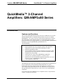
Crestron QM-AMP3x80 Series
QuickMedia™ 3-Channel Amplifiers
Operations Guide
This document was prepared and written by the Technical Documentation department at:
Crestron Electronics, Inc.
15 Volvo Drive
Rockleigh, NJ 07647
1-888-CRESTRON
Important Safety Instructions
•
Read and keep these instructions.
•
Heed all warnings.
•
Clean only with a dry cloth.
•
To prevent shock or fire hazard, do not expose the device to rain or moisture.
•
Install in accordance with the included instructions.
•
Do not block any ventilation openings.
•
Disconnect power prior to connecting or disconnecting equipment
•
Do not defeat the safety purpose of the supplied grounding-type plug. The groundingtype plug has two blades and a third grounding prong. The third prong is provided for
your safety. If the provided plug does not fit into your outlet, consult an electrician for
replacement of the outlet.
•
Protect the power cord and other cables so items placed on or against them cannot
cause damage.
•
Prevent foreign objects from entering the device.
•
Refer all servicing to qualified service personnel. Servicing is required when the
apparatus has been damaged in any way, such as power supply cord or plug is
damaged, liquid has been spilled or objects have fallen into the device, the device has
been exposed to rain or moisture, does not operate normally, or has been dropped.
WARNING:
TO PREVENT ELECTRIC SHOCK, DO NOT REMOVE COVER. THERE ARE NO USER
SERVICEABLE PARTS INSIDE. ONLY QUALIFIED SERVICE PERSONNEL SHOULD
PERFORM SERVICE.
IMPORTANT:
The QM-AMP3x80 series of amplifiers require Class 2 output wiring.
All brand names, product names and trademarks are the property of their respective owners.
©2004 Crestron Electronics, Inc.
Crestron QM-AMP3x80 Series
QuickMedia™ 3-Channel Amplifiers
Contents
QuickMedia™ 3-Channel Amplifiers: QM-AMP3x80 Series
1
Introduction ............................................................................................................................... 1
Features and Functions ................................................................................................ 1
Applications................................................................................................................. 2
Specifications .............................................................................................................. 3
Physical Description.................................................................................................... 4
Industry Compliance ................................................................................................... 7
Setup .......................................................................................................................................... 8
Network Wiring........................................................................................................... 8
Identity Code ............................................................................................................... 9
Rack Mounting .......................................................................................................... 12
Stacking..................................................................................................................... 13
Hardware Hookup ..................................................................................................... 13
Configuration Software ........................................................................................................... 15
Earliest Version Software Requirements for the PC ................................................. 15
Configuring with Crestron SystemBuilder ................................................................ 16
Configuring with SIMPL Windows .......................................................................... 16
Uploading and Upgrading........................................................................................................ 20
Communication Settings ........................................................................................... 20
Uploading a SIMPL Windows Program.................................................................... 22
Firmware Upgrade..................................................................................................... 24
Problem Solving ...................................................................................................................... 25
Troubleshooting......................................................................................................... 25
Further Inquiries ........................................................................................................ 26
Future Updates .......................................................................................................... 26
Return and Warranty Policies .................................................................................................. 27
Merchandise Returns / Repair Service ...................................................................... 27
CRESTRON Limited Warranty................................................................................. 27
Operations Guide - DOC. 6272
Contents • i
Crestron QM-AMP3x80 Series
QuickMedia™ 3-Channel Amplifiers
QuickMedia™ 3-Channel
Amplifiers: QM-AMP3x80 Series
Introduction
Features and Functions
The Crestron® QM-AMP3x80 (hereinafter referred to as AMP3x80) series of threechannel amplifiers deliver exceptional audio performance as part of a complete
MediaManager™ AV system or anywhere multi-channel amplification is required.
Each model features three amplifier channels to complement the discrete stereo
program and mono speech output channels of Crestron's QM-MD7x2 QuickMedia™
Distribution Center and QM-RMCRX QuickMedia Receiver.
Functional Summary
•
•
•
•
•
•
•
•
•
Four models for domestic and international use
Built-in amplifiers drive stereo program speakers and/or distributed
loudspeakers for speech reinforcement (depending on model)
Balanced and unbalanced audio
Class G amplifier topology puts more output power in less space while
generating less heat when compared to conventional amplifier designs
One Rack Unit (1 RU) height
Optimized for use with Crestron MediaManager components
Can operate as a stand-alone amplifier or a Cresnet® device
Built-in power control and internal temperature monitoring via Cresnet
from any 2-Series or MediaManager control system
Touch-settable ID (TSID) ready
The AMP3x80 series feature class G topology to provide power for driving a pair of
program loudspeakers and/or distributed ceiling loudspeakers for speech
reinforcement. The class G design provides more output power while using less
space and generating significantly less heat. The AMP3x80 series feature a fixed
input gain that has been optimized for use with Crestron’s line of MediaManager
components.
Four models make up the AMP3x80 series of amplifiers. Refer to “Specifications”
on page 3 for details of each model.
Operations Guide – DOC. 6272
QuickMedia™ 3-Channel Amplifiers: QM-AMP3x80 Series • 1
QuickMedia™ 3-Channel Amplifiers
Crestron QM-AMP3x80 Series
Applications
The AMP3x80 series of amplifiers are part of the Crestron MediaManager line of
integrated presentation solutions. They are ideally suited to work with Crestron’s
MediaManager wall plate media centers, FlipTop media centers, receivers and
control processors to provide an integrated solution for amplifying program audio
and microphone signals in a presentation system. MediaManager devices are
designed for conference room, auditorium, and lecture hall applications, or anywhere
else where audio, video, or computer equipment needs to be easily connected and
disconnected from a presentation system or room control system.
Of the four models in the AMP3x80 series, two are designated for international use.
All of the features are identical to the US versions with the exceptions of the power
output rating for the speech channels, the international AC power requirements, the
power cord, and the unit nomenclature of QMI-AMP3x80SR (where “SR” stands for
“Speech Reinforcement”) and QMI-AMP3x80MM (where “MM” stands for “Multi
Media”). Throughout this operations guide, all references to AMP3x80 apply to the
US and international versions except where noted.
The following diagram shows an AMP3x80 in a lectern application.
QM Solution in Lectern using QM-AMP3x80MM
2 • QuickMedia™ 3-Channel Amplifiers: QM-AMP3x80 Series
Operations Guide – DOC. 6272
Crestron QM-AMP3x80 Series
QuickMedia™ 3-Channel Amplifiers
Specifications
The following table provides specifications for the QM-AMP3x80 series of
amplifiers.
QM-AMP3x80 Series Specifications
SPECIFICATION
DETAILS
Cresnet Power Requirements
3 Watts (24VDC @ 0.125A)
Default Net ID
09
Control System Update Files
2-Series Control System
1, 2
Channels
Version C2-V3.093.CUZ or later
3
Balanced Output Power:
QM-AMP3x80MM
80 Watts/Channel into 8-ohm loads/110
Watts/Channel into 4-ohm loads (x2), 80 Watts at
70 V (x1)
QMI-AMP3x80MM
80 Watts/Channel into 8-ohm loads/110
Watts/Channel into 4-ohm loads (x2), 80 Watts at
100 V (x1)
QM-AMP3x80SR
80 Watts at 70 V (x3)
QMI-AMP3x80SR
80 Watts at 100 V (x3)
Input Impedance
Balanced: 19k ohms
Unbalanced: 9.5k ohms
Input Sensitivity
1.2 Vrms for rated power (80 W / 8 ohms)
Power Bandwidth
75 W, 20-20k Hz, 8 ohms
95 W, 20-20k Hz, 4 ohms
75 W, 100-20k Hz, 70/100 V outputs
Frequency Response
20-20k Hz, +0 dB / -0.5 dB 4 / 8 ohm outputs
Total Harmonic Distortion (1k Hz)
< 0.1% @ 1 Watt into 4 and 8 ohms
100-20k Hz, +0 dB / -3 dB, 70 / 100 V outputs
< 0.1% @ 75 Watts into 8 ohms
< 0.2% @ 100 Watts into 4 ohms
< 0.1% @ 1 and 75 Watts into 70/100 V outputs
Signal to Noise Ratio (S/N) “A” Weighted
110dB below rated output power, A-weighted
Damping Factor
> 150 (4/8 ohm outputs)
QM-AMP3x80 Firmware
QM-AMP3x80.v2.0.upg or later
Rack Space Required
1U
Power Input Requirements:
QM-AMP3x80MM, QM-AMP3x80SR
QMI-AMP3x80MM, QMI-AMP3x80SR
Environmental Temperature &
Humidity
120 VAC +15%/-25%, 60 Hz
230 VAC +15%/-25%, 50 Hz
32 to 104° F (0 to 40°C)
10 to 90% RH (non-condensing)
Dimensions & Weight
1.
2.
Height: 1.96 in (4.99 cm)
Width: 19.00 in (48.26 cm) – with ears
17.01 in (43.21 cm) – without ears
Depth: 12.53 in (31.82 cm)
Weight: AMP3x80MM: 15.2 lb (6.9 kg)
AMP3x80SR: 17.4 lb (7.9 kg)
The latest software versions can be obtained from the Downloads | Software Updates section of the
Crestron website (www.crestron.com). Refer to the NOTE following these footnotes.
Crestron 2-Series control systems include the AV2 and PRO2. Consult the latest Crestron Product
Catalog for a complete list of 2-Series control systems.
NOTE: Crestron software and any files on the website are for Authorized Crestron
dealers and Crestron Authorized Independent Programmers (CAIP) only. New users
may be required to register to obtain access to certain areas of the site (including the
FTP site).
Operations Guide – DOC. 6272
QuickMedia™ 3-Channel Amplifiers: QM-AMP3x80 Series • 3
QuickMedia™ 3-Channel Amplifiers
Crestron QM-AMP3x80 Series
Physical Description
The AMP3x80 is housed in a black enclosure with labeling on the front and rear
panels. The front panel has a master power switch and LED to indicate AC power.
All audio input and output, Cresnet system, and power connections are made on the
rear panel. The rear panel also has a switch that bypasses Cresnet control so the
amplifier can operate in a stand-alone configuration. A pushbutton on the rear panel
with an accompanying LED is used to set the AMP3x80’s network ID. Refer to the
following illustrations of the front and rear panels and the physical views.
Two mounting ears are provided for rack mounting, and four round rubber feet are
preinstalled for stability and to prevent slippage in tabletop placement or stacking
configurations. For information on rack mounting and use of the rubber feet, refer to
“Rack Mounting” on page 12.
QM-AMP3x80MM
QM-AMP3x80SR
4 • QuickMedia™ 3-Channel Amplifiers: QM-AMP3x80 Series
Operations Guide – DOC. 6272
Crestron QM-AMP3x80 Series
QuickMedia™ 3-Channel Amplifiers
QM-AMP3x80 Physical Views
1.96 in
(4.99 cm)
12.53 in
(31.82 cm)
17.01 in
(43.21 cm)
AMP3x80SR
18.52 in
(47.04 cm)
19.00 in
(48.26 cm)
AMP3x80MM
NOTE: The rear panel of the AMP3x80MM, which has different connectors than
the AMP3x80SR, is shown on the bottom of the diagram. For a detailed view, refer
to “Hardware Hookup” on page 13.
Ports
All connections to the AMP3x80 are made through the ports on the rear panel. Refer
to the illustrations and descriptions that follow.
NOTE: Interface connectors for the NET and audio ports are provided with the
AMP3x80.
Operations Guide – DOC. 6272
QuickMedia™ 3-Channel Amplifiers: QM-AMP3x80 Series • 5
QuickMedia™ 3-Channel Amplifiers
Crestron QM-AMP3x80 Series
INPUTS
The AMP3x80 contains three sets of balanced/unbalanced, line-level audio inputs.
On the QM/QMI-AMP3x80MM, two of the inputs are reserved for program audio
and one input is reserved for speech audio. The inputs are labeled to designate
program and speech audio. On the QM/QMI-AMP3x80SR, all of the inputs are
designated for speech audio.
Each input port uses a 3-position mini-terminal block connector for connecting the
audio output of a QM-RMCRX, QM-MD7x2, or other preamp. For wiring
information, refer to “Hardware Hookup” on page 13.
OUTPUTS
The AMP3x80 contains three sets of balanced speaker outputs. The QM/QMIAMP3x80MM has two outputs that are reserved for the left and right channels of the
audio program (4/8 ohm impedance) and one output that is reserved for speech audio
distribution (70 V or 100 V output). The outputs are labeled to designate program
and speech audio. On the QM/QMI-AMP3x80SR, all of the outputs are for audio
distribution (70 V or 100 V).
Each output port uses a 2-position terminal block connector for connecting the
appropriate type speaker. For wiring information, refer to “Hardware Hookup” on
page 13.
NET
This 4-position mini-terminal block connector is used to connect the AMP3x80 to the
Cresnet system. Data and network power for the AMP3x80 are provided via the
connection. Refer to “Network Wiring” on page 8 for more information.
5A SLO-BLO 250V (T2.5A 250V on QMI)
This port holds the operating fuse for the AMP3x80. If the fuse is blown, replace
with the type described on the label. On the QM-AMP3x80SR and
QM-AMP3x80MM, the port is labeled 5A SLO-BLO 250V. The port on the
QMI-AMP3x80SR and QMI-AMP3x80MM is labeled T2.5A 250V.
WARNING: Only use the specified type of fuse when replacing a blown fuse.
Failure to do so may cause damage to the amplifier.
120V ~50-60 Hz (230V ~50-60 Hz on QMI)
This IEC-320-C-14 port is used to connect the AMP3x80 to an AC outlet. On the
QM-AMP3x80SR and QM-AMP3x80MM, the port is labeled 120V ~50-60 Hz. The
QMI-AMP3x80SR and QMI-AMP3x80MM are labeled 230V ~50-60 Hz. Use the
supplied power cord to connect to an AC outlet.
6 • QuickMedia™ 3-Channel Amplifiers: QM-AMP3x80 Series
Operations Guide – DOC. 6272
Crestron QM-AMP3x80 Series
QuickMedia™ 3-Channel Amplifiers
Switches, Buttons, and Indicators
POWER
This two-position switch, located on the front panel, turns operating power to the
AMP3x80 circuitry on and off. A built-in LED indicates when the switch is in the
“ON” position. The switch must be in the “ON” position when the unit is to be
controlled by the "control system or when it is operating as a stand-alone unit.
PWR (BYPASS/NET CONTROL)
This two-position switch, located on the rear panel, is used to override Cresnet
control of the amplifier so it can operate as a stand-alone unit. When the switch is in
the NET CONTROL position, the amplifier will be controlled and monitored by the
Crestron control system (the amplifier must be connected to a Crestron control
system running a program that includes the amplifier). When the switch is in the
BYPASS position, the amplifier will operate independently of the control system.
SETUP LED and Pushbutton
The AMP3x80 devices are TSID ready. Located on the rear of each device, the
SETUP pushbutton and its associated LED are used for setting up the unit’s network
ID during the initial configuration of a Cresnet system or when the device is being
added/replaced. Refer to “Method B (Touch Settable ID)” on page 10 for detailed
information.
PWR (Power)
This LED, located on the rear panel, illuminates when 24 VDC is supplied to the
AMP3x80 and the POWER switch on the front panel is in the “ON” position.
NET
This LED, located on the rear panel, illuminates when communication between the
control system and the AMP3x80 is established (the unit is polled on the network).
Illumination indicates that the SIMPL Windows program currently loaded has a
network device defined at the same Net ID as the AMP3x80. The LED flashes when
communication with the processor occurs.
Industry Compliance
As of the date of manufacture, this unit has been tested and found to comply with
specifications for CE marking and standards per EMC and Radio Communications
Compliance Labeling (N11785)
Operations Guide – DOC. 6272
QuickMedia™ 3-Channel Amplifiers: QM-AMP3x80 Series • 7
QuickMedia™ 3-Channel Amplifiers
Crestron QM-AMP3x80 Series
NOTE: This device complies with part 15 of the FCC rules. Operation is subject to
the following two conditions: (1) this device may not cause harmful interference, and
(2) this device must accept any interference received, including interference that may
cause undesired operation.
This equipment has been tested and found to comply with the limits for a Class B
digital device, pursuant to part 15 of the FCC Rules. These limits are designed to
provide reasonable protection against harmful interference in a residential
installation. This equipment generates, uses and can radiate radio frequency energy
and, if not installed and used in accordance with the instructions, may cause harmful
interference to radio communications. However, there is no guarantee that
interference will not occur in a particular installation. If this equipment does cause
harmful interference to radio or television reception, which can be determined by
turning the equipment off and on, the user is encouraged to try to correct the
interference by one or more of the following measures:
Reorient or relocate the receiving antenna.
Increase the separation between the equipment and receiver.
Connect the equipment into an outlet on a circuit different from that to which the
receiver is connected.
Consult the dealer or an experienced radio/TV technician for help.
Setup
Network Wiring
CAUTION: Use only Crestron power supplies for Crestron equipment. Failure to
do so could cause equipment damage or void the Crestron warranty.
CAUTION: Provide sufficient power to the system. Insufficient power can lead to
unpredictable results or damage to the equipment. Please use the Crestron Power
Calculator (http://www.crestron.com/dealer-tech_resources/power_calculator.asp) to
help calculate how much power is needed for the system.
CAUTION: Possible equipment damage if miswired.
NOTE: When installing network wiring, refer to the latest revision of the wiring
diagram(s) appropriate to your specific system configuration, available from the
Downloads | Product Manuals | Wiring Diagrams section of the Crestron website
(www.crestron.com).
NOTE: Do not power up system until all wiring is verified. Care should be taken to
ensure data (Y, Z) and power (24, G) connections are not crossed.
When calculating the wire gauge for a particular Cresnet run, the length of the run
and the power factor of each Cresnet unit to be connected must be taken into
consideration. If Cresnet units are to be daisy-chained on the run, the power factor of
each network unit to be daisy-chained must be added together to determine the
power factor of the entire chain. The length of the run in feet and the power factor of
8 • QuickMedia™ 3-Channel Amplifiers: QM-AMP3x80 Series
Operations Guide – DOC. 6272
Crestron QM-AMP3x80 Series
QuickMedia™ 3-Channel Amplifiers
the run should be used in the following resistance equation to calculate the value on
the right side of the equation.
Resistance Equation
R < 40,000
L x PF
Where: R = Resistance (refer to table below).
L = Length of run (or chain) in feet.
PF = Power factor of entire run (or chain).
The required wire gauge should be chosen such that the resistance value is less than
the value calculated in the resistance equation. Refer to the table after this paragraph.
Wire Gauge Values
RESISTANCE (R)
WIRE GAUGE
4
16
6
18
10
20
15
22
13
Doubled CAT5
8.7
Tripled CAT5
NOTE: All network wiring must consist of two twisted pairs. One twisted pair is
the +24V conductor and the GND conductor. The other twisted pair is the Y and Z
conductors.
NOTE: When daisy-chaining Cresnet units, strip the ends of the wires carefully to
avoid nicking the conductors. Twist together the ends of the wires that share a pin on
the network connector, and tin the twisted connection. Apply solder only to the ends
of the twisted wires. Avoid tinning too far up the wires or the end becomes brittle.
Insert the tinned connection into the Cresnet connector and tighten the retaining
screw. Repeat the procedure for the other three conductors.
NOTE: For larger networks (i.e., greater than 28 network devices), it may become
necessary to add a Cresnet Hub/Repeater (CNXHUB) or Cresnet Network Poll
Accelerator (C2N-NPA8) to maintain signal quality throughout the network. Also,
for networks with lengthy cable runs, it may be necessary to add a Hub/Repeater
after only 20 devices.
Identity Code
All equipment and user interfaces within the network require a unique identity code
(Net ID). These codes are two-digit hexadecimal numbers from 03 to FE. The Net ID
of each unit must match an ID code specified in the SIMPL Windows program.
Refer to “Setting the Net ID in Device Settings” on page 18 for details of the SIMPL
Windows procedure.
Refer to the note on page 20 for a
definition of Viewport.
The Net ID of the AMP3x80 has been factory set to 09. The Net IDs of multiple
AMP3x80s in the same system must be unique. Net IDs are changed from a
personal computer (PC) via the Crestron Viewport.
NOTE: For detailed information on establishing communication between the PC and
control system, refer to “Communication Settings” on page 20. If communication
cannot be established, refer to the “Troubleshooting Communications” section in the
respective Operations Guide for the control system.
Operations Guide – DOC. 6272
QuickMedia™ 3-Channel Amplifiers: QM-AMP3x80 Series • 9
QuickMedia™ 3-Channel Amplifiers
Crestron QM-AMP3x80 Series
There are two different methods—Method A or Method B—for setting the Net ID:
Method A (Cresnet address-settable ID), described below, applies to devices in a
Cresnet system with a 2-Series control system that require a single unit be the only
network device connected to the control system.
Method B (Touch Settable ID or TSID), which begins below, applies to all TSIDready devices in a Cresnet system with 2-Series control system upgrade file (CUZ)
version 3.029 or later. TSID functionality makes it possible for the control system to
recognize a network device via its serial number, which is stored in the device’s
memory. This method does not require that any devices be disconnected from the
network; Net IDs may be set with the entire Cresnet system intact. This method
requires the use of the Crestron Viewport version 3.35 or later.
Use the appropriate method to set the Net ID.
Method A (Cresnet address-settable ID)
1.
Ensure that the device requiring a Net ID change is the only unit
connected to the control system.
2.
Open the Crestron Viewport.
3.
From the Viewport menu, select Functions | Set Network ID. The
software checks the baud rate and then opens the "Set Network ID"
window.
4.
In the "Set Network ID" window, select the device requiring a Net ID
change from the Current Network Devices text window.
5.
Select the new Net ID for the device from the Choose the new network
ID for the selected device (Hex): text box.
6.
Click Set ID to initiate the change. This will display the "ID command
has been sent" window.
7.
In the "Command Complete" window, click OK.
8.
In the Current Network Devices text window, verify the new Net ID
code.
9.
In the "Set Network ID" window, click Close.
NOTE: The new Net ID code may also be verified by selecting Diagnostic | Report
Network Devices in the Viewport (alternately, select F4).
10. Repeat this procedure for each additional network device requiring a
Net ID change.
Method B (Touch Settable ID)
Before using this method, you should have a list of all current network devices and
their Net IDs, to avoid assigning duplicate IDs.
Set Net ID by TSID
These procedures are for TSID-enabled network devices during the initial
configuration of a Cresnet system or when such devices are being added/replaced.
1.
Ensure that all network devices are connected to the control system.
2.
Open the Crestron Viewport version 3.35 or later.
10 • QuickMedia™ 3-Channel Amplifiers: QM-AMP3x80 Series
Operations Guide – DOC. 6272
Crestron QM-AMP3x80 Series
QuickMedia™ 3-Channel Amplifiers
3.
From the Viewport menu, select Functions | Assign Cresnet ID by
Serial Number. The “Set Net ID by TSID” window appears, shown
below. The window is first displayed with the data fields empty.
4.
Click on the Search for Touch Settable Devices button. The system
searches the network and lists all TSID-enabled devices found. The list
is similar to the report produced by pressing F4 (Report Network
Devices); the first eight digits of each line constitute the TSID number
(hexadecimal form of the serial number).
“Set Net ID by TSID” Window
5.
Enter either the serial number or TSID number of the device that
requires a change. The list scrolls to and highlights the device listing.
The listing should show the device’s default Cresnet ID (a.k.a. Net ID).
6.
Enter the Cresnet ID that the device should be set to and click OK. The
number you enter should appear on the list.
CAUTION: This function does not prevent you from setting duplicate IDs. Be sure
to check current assignments before entering the desired Cresnet ID number.
Serial Number to TSID Conversion
This utility is useful in a case where there are multiple devices of the same type on a
network, you need to locate a particular one, you know the TSID but not the serial
number, and your site installation list is based on device serial numbers. In this (or
the reverse) situation, do the following:
Operations Guide – DOC. 6272
1.
Open the Crestron Viewport.
2.
From the Viewport menu, select Functions | Serial Number
TSID Conversion Tool. The “Serial Number
TSID Conversion
Tool” window is displayed.
QuickMedia™ 3-Channel Amplifiers: QM-AMP3x80 Series • 11
QuickMedia™ 3-Channel Amplifiers
Crestron QM-AMP3x80 Series
“Serial Number to TSID Conversion Tool” Window
3.
Enter the serial number or TSID number as instructed; press the
appropriate button to obtain the corresponding number.
NOTE: Enter serial numbers, including spaces, exactly as they appear on the unit
label. Alpha characters in serial numbers or TSID numbers may be entered in upper
or lower case.
Rack Mounting
WARNING: To prevent bodily injury when mounting or servicing this unit in a
rack, take special precautions to ensure that the system remains stable. The following
guidelines are provided to ensure your safety:
When mounting this unit in a partially filled rack, load the rack from the
bottom to the top with the heaviest component at the bottom of the rack.
If the rack is provided with stabilizing devices, install the stabilizers before
mounting or servicing the unit in the rack.
NOTE: If rack mounting is not required, rubber feet are preinstalled for tabletop
mounting or stacking. Refer to “Stacking” on page 13 for details.
NOTE: Reliable earthing of rack-mounted equipment should be maintained.
Particular attention should be given to supply connections other than direct
connections to the branch circuit. (e.g., use of power strips).
NOTE: There is no specific amount of clearance required between components in a
rack. However, if there are multiple amplifiers or heat-generating devices stored in a
closed rack, the amplifier should be placed below other equipment as it dissipates
heat from the bottom. Putting an open space between the components or providing
proper ventilation for the equipment in the rack can prolong the life of the amplifier.
Two “ears” are provided with the AMP3x80 so that the unit can be rack mounted.
These ears must be installed prior to mounting. Complete the following procedure to
attach the ears to the unit. The only tool required is a #2 Phillips screwdriver.
1.
There are several screws (#6-32 x 0.5" L) that secure each side of the
AMP3x80 top cover. Using a #2 Phillips screwdriver, remove the two
screws closest to the front panel from one side of the unit. Refer to the
diagram following step 3 for a detailed view.
12 • QuickMedia™ 3-Channel Amplifiers: QM-AMP3x80 Series
Operations Guide – DOC. 6272
Crestron QM-AMP3x80 Series
QuickMedia™ 3-Channel Amplifiers
2.
Position a rack ear so that its mounting holes align with the holes
vacated by the screws in step 1.
3.
Secure the ear to the unit with the two screws from step 1, as shown in
the following diagram.
Ear Attachment for Rack Mounting
USE COVER SCREWS
4.
Repeat procedure (steps 1 through 3) to attach the remaining ear to the
opposite side.
Stacking
Four "feet" are preinstalled on the AMP3x80 so that if the unit is not rack mounted,
the rubber feet can provide stability when the unit is placed on a flat surface or
stacked.
Hardware Hookup
Refer to the following hookup diagrams for the appropriate AMP3x80 model and,
aside from attaching power last, complete the connections in any order. Refer to
“Network Wiring” on page 8 when making network connections.
WARNING: To prevent injury and / or equipment damage due to electric shock,
disconnect power from the AMP3x80 prior to making any wiring connections.
NOTE: Use only the supplied power cord, or equivalent, to connect to the AC
power source.
NOTE: To prevent overheating, do not operate this product in an area that exceeds
the environmental temperature range listed in the table of specifications.
Consideration must be given if installed in a closed or multi-unit rack assembly since
the operating ambient temperature of the rack environment may be greater than the
room ambient. Contact with thermal insulating materials should be avoided on all
sides of the unit.
NOTE: The maximum continuous current from equipment under any external load
conditions shall not exceed a current limit that is suitable for the minimum wire
gauge used in interconnecting cables. The ratings on the connecting unit's supply
input should be considered to prevent overloading the wiring.
Operations Guide – DOC. 6272
QuickMedia™ 3-Channel Amplifiers: QM-AMP3x80 Series • 13
QuickMedia™ 3-Channel Amplifiers
Crestron QM-AMP3x80 Series
Hardware Connections for the QM-AMP3x80MM (Back of the Unit is Shown)
AUDIO INPUTS:
FROM AUDIO
SOURCES
STEREO OUTPUT:
TO 4/8 OHM
SPEAKERS
CRESNET:
TO CONTROL SYSTEM AND
OTHER CRESNET DEVICES
FROM
LINE
VOLTAGE
SPEECH OUTPUT:
TO LOUDSPEAKER
NOTE: The QMI-AMP3x80MM speech output is rated at 100V.
Hardware Connections for the QM-AMP3x80SR (Back of the Unit is Shown)
AUDIO INPUTS 1-3:
FROM AUDIO
SOURCES
OUTPUTS 1-3:
TO DISTRIBUTED
LOUDSPEAKERS
CRESNET:
TO CONTROL SYSTEM AND
OTHER CRESNET DEVICES
FROM
LINE
VOLTAGE
NOTE: The QMI-AMP3x80SR outputs are rated at 100V.
Connecting Audio Sources
The AMP3x80 can receive balanced or unbalanced audio input signals. Refer to the
following diagrams when connecting balanced and unbalanced sources to the signal
inputs on the AMP3x80.
Wiring for Unbalanced Audio (left) and Balanced Audio (right)
+ - G
+ - G
Signal
Ground
Jumper
Signal +
Ground
Signal -
Connecting Speakers to Audio Outputs
Each model in the AMP3x80 series is equipped with three speaker outputs.
The AMP3x80MM uses one of the speaker outputs for a 70V public address speaker,
while the two remaining outputs can be connected to a pair of 4/8 ohm stereo
speakers. On the QMI-AMP3x80MM, the public address speaker output is rated for
use with a 100V public address speaker.
14 • QuickMedia™ 3-Channel Amplifiers: QM-AMP3x80 Series
Operations Guide – DOC. 6272
Crestron QM-AMP3x80 Series
QuickMedia™ 3-Channel Amplifiers
The QM-AMP3x80SR has three outputs that are rated for use with three 70V public
address speakers. The outputs on the QMI-AMP3x80SR are rated for use with 100V
public address speakers.
WARNING: The audio outputs operate at high voltage/current. Disconnect power
prior to connecting speakers to avoid damage to equipment.
Configuration Software
Have a question or comment about Crestron software?
Answers to frequently asked questions (FAQs) can be viewed in the Online Help
section of the Crestron website (www.crestron.com). To post a question or view
questions you have submitted to Crestron’s True Blue Support, log in at
http://support.crestron.com. First-time users will need to establish a user account.
Configuration is easy thanks to Crestron’s Windows-based programming software.
Crestron SystemBuilder™ software creates a complete project, with no special
programming required. SystemBuilder completes all necessary programming for a
base system including all touchpanel screens and the control system program. The
program output of SystemBuilder is a SIMPL Windows program with much of the
functionality encapsulated in macros and templates. Once SystemBuilder creates the
project, the system interfaces and program logic can be customized in SystemBuilder
or can be easily modified with Crestron development tools (i.e., SIMPL Windows
and Crestron VisionTools® Pro-e (VT Pro-e) software packages).
SystemBuilder comes with templates for all supported interfaces. If a user wishes to
create a touchpanel project using templates with a different look-and-feel, this can be
accomplished by making a custom template. This custom template can then be used
by SystemBuilder to create the final project files to be loaded into the panels.
Alternatively, VT Pro-e can be used to tweak projects created with the
SystemBuilder or develop original touchpanel screen designs.
Once the program created by SystemBuilder is loaded into the control system,
Digital Media Tools (DMT) Software can be used to tune the system for optimal
performance. DMT software can be used to test the quality of audio and video
signals as well as fine-tune audio and video settings.
Earliest Version Software Requirements for the PC
NOTE: Crestron recommends the use of SystemBuilder and Digital Media Tools
software for creating and fine-tuning a QuickMedia system.
NOTE: Crestron recommends that you use the latest software to take advantage of
the most recently released features. The latest software is available from the
Downloads | Software Updates section of the Crestron website (www.crestron.com).
NOTE: Crestron software and any files on the website are for Authorized Crestron
dealers and Crestron Authorized Independent Programmers (CAIP) only. New users
may be required to register to obtain access to certain areas of the site (including the
FTP site).
Operations Guide – DOC. 6272
QuickMedia™ 3-Channel Amplifiers: QM-AMP3x80 Series • 15
QuickMedia™ 3-Channel Amplifiers
Crestron QM-AMP3x80 Series
The following are the earliest useable software version requirements for the PC:
•
(Optional) SystemBuilder (Requires SIMPL Windows).
•
SIMPL Windows version 2.05.08 or later with library update file 291.
Requires SIMPL+® Cross Compiler version 1.1.
•
Crestron Database version 16.2.0 or later. Required by SIMPL Windows.
•
Digital Media Tools software version 3.01.00 or later.
Configuring with Crestron SystemBuilder
NOTE: The AMP3x80 is configured with Crestron SystemBuilder version 1.0
software. As of press time, this version of Crestron SystemBuilder had not been
released. Please check the Crestron FTP site.
The Crestron SystemBuilder interface guides you through a few basic steps for
specifying the control system, designating rooms and touchpanels, devices, and
functionality. The Crestron SystemBuilder then configures the system, including all
touchpanel projects and control system logic, including Crestron RoomView™
management software.
The Crestron SystemBuilder is fully integrated with the Crestron suite of software
development tools, including SIMPL Windows, Cross Compiler, VT Pro-e, Crestron
Database, User IR Database, and User Modules Directory. The Crestron
SystemBuilder accesses all these tools behind the scenes, enabling you to easily
create robust systems.
SystemBuilder provides a step-by-step process that guides the user through the
process of selecting components and determining signal routing and control. The
control code and complete equipment lists are automatically generated. Crestron
SystemBuilder automatically compiles and uploads your program to the control
system.
A template is provided with SystemBuilder to allow easy configuration. After
entering the appropriate information in each step, SystemBuilder creates the control
system logic and touchpanel pages, ready to upload to the controller.
NOTE: After uploading the program to the control system and installing the
hardware, values for properties such as volume, balance, treble and bass can be
adjusted as required.
For additional details, download SystemBuilder from the Crestron website
(www.crestron.com) and examine the extensive help file.
Configuring with SIMPL Windows
NOTE: While SIMPL Windows can be used to configure the AMP3x80, Crestron
recommends SystemBuilder and Digital Media Tools software for configuring and
tuning a QuickMedia system.
NOTE: The following are acceptable file extensions for programs that include a
QM-RMCRX and an AMP3x80, developed for specific control system types:
.smw projectname.smw (source file)
.spz projectname.spz (compiled file for 2-Series)
.usp projectname.usp (source code module for SIMPL+)
16 • QuickMedia™ 3-Channel Amplifiers: QM-AMP3x80 Series
Operations Guide – DOC. 6272
Crestron QM-AMP3x80 Series
QuickMedia™ 3-Channel Amplifiers
.ir
projectname.ir (user IR)
.umc projectname.umc (user macro)
.ush projectname.ush (completed SIMPL+)
SIMPL Windows is the Crestron graphical, Windows®-based development tool for
programming control systems. The SIMPL Windows interface provides two
workspaces: the Configuration Manager, for configuring the control system,
touchpanels, and controlled network devices; and Program Manager, for designing
the logic and functionality of the control system.
In addition, you can use the powerful Crestron Viewport utility to accomplish
multiple system tasks, such as uploading the program to the control system and
performing diagnostic functions. Together with the Crestron Database, these tools
provide you with the essential components you need to program the QM-RMCRX
and AMP3x80. Crestron software is available from the Crestron website
(www.crestron.com) — registration is required for downloading.
NOTE: Crestron software and any files on the website are for Authorized Crestron
dealers and Crestron Authorized Independent Programmers (CAIP) only. New users
may be required to register to obtain access to certain areas of the site (including the
FTP site).
NOTE: The information in this section assumes that the reader has knowledge of
SIMPL Windows. If not, refer to the extensive help information provided with the
software.
NOTE: In the following example, a QM-RMCRX is used as the QuickMedia
receiver for the AMP3x80.
In Configuration Manager, drag the QM-RMCRX from the Control Systems folder
of the Device Library to System Views.
QM-RMCRX System View
The System Views lower pane displays the QM-RMCRX system tree. This tree can
be expanded to display and configure the communications ports.
Expanded QM-RMCRX System Tree
Operations Guide – DOC. 6272
QuickMedia™ 3-Channel Amplifiers: QM-AMP3x80 Series • 17
QuickMedia™ 3-Channel Amplifiers
Crestron QM-AMP3x80 Series
C2Net-Device Slot in Configuration Manager
To incorporate an AMP3x80 into the system, drag the QM-AMP3x80 from the
Cresnet Control Modules | QM Series folder of the Device Library and drop it in
System Views. The QM-RMCRX system tree displays the QM-AMP3x80 in Slot 5,
with a default Net ID of 09 as shown in the following illustration.
NOTE: The first AMP3x80 in a system is preset with a Net ID of 09 when its
symbol is dragged into the upper pane of System Views. Additional units are assigned
different Net ID numbers as they are added.
C2Net Device, Slot 5
Setting the Net ID in Device Settings
Double-click the QM-AMP3x80 icon in the upper pane to open the “Device
Settings” window. This window displays QM-AMP3x80 device information. The
Net ID can be changed in this window using the Net ID tab, as shown in the
following figure.
“QM-AMP3x80 Device Settings” Window
NOTE: This procedure sets the Net ID for the AMP3x80 in the program only. It
does not automatically set the Net ID for the AMP3x80 itself. SIMPL Windows
automatically changes Net ID values of a device added to a program if a duplicate
device or a device with the same Net ID already exists in the program. Always
ensure that the hardware and software settings of the Net ID match. For Net ID
hardware setting details, refer to “Identity Code” on page 9.
18 • QuickMedia™ 3-Channel Amplifiers: QM-AMP3x80 Series
Operations Guide – DOC. 6272
Crestron QM-AMP3x80 Series
QuickMedia™ 3-Channel Amplifiers
QM-AMP3x80 Symbol in Programming Manager
Programming Manager is where programmers “program” a Crestron control system
by assigning signals to symbols. The following describes the AMP3x80 symbol in
the SIMPL Windows Programming Manager.
QM-AMP3x80 symbol in SIMPL Windows Programming Manager
QM-AMP3x80 Digital Input Signal Descriptions
INPUT
Main_Power
Enable_Temp_Rpt
Temp_Format
DESCRIPTION
Activates the main operating power to the
AMP3x80 circuitry for as long as <Main_Power>
remains high. When the signal goes low, main
power shuts off. The POWER switch on the front
panel must be in the ON position. The PWR
switch on the rear panel must be in the NET
CONTROL position
If this signal is high, the internal temperature
value will update every 2 seconds.
If this signal is high, the temperature will be
displayed in degrees Celsius; if low, degrees
Fahrenheit.
QM-AMP3x80 Digital Output Signal Description
OUTPUT
DESCRIPTION
Goes high whenever the PWR switch on the
back of the AMP3x80 is in the BYPASS position.
OverRide_F
QM-AMP3x80 Analog Output Signal Descriptions
OUTPUT
Temp(x10)
DESCRIPTION
Reports the temperature inside the AMP3x80
enclosure and updates that value every two
seconds as long as Enable_Temp_Rpt is high.
Example Program
An example program for the AMP3x80 is available from the Crestron FTP site
(ftp://ftp.crestron.com/Examples/). Search for the file named
QM-AMP3x80_DEMO.ZIP that contains the example program, associated files and
a README.TXT file that describes the program.
Operations Guide – DOC. 6272
QuickMedia™ 3-Channel Amplifiers: QM-AMP3x80 Series • 19
QuickMedia™ 3-Channel Amplifiers
Crestron QM-AMP3x80 Series
Uploading and Upgrading
Assuming a PC is properly connected to the entire system, Crestron programming
software allows the programmer to upload programs and projects after their
development to the system and network devices. However, there are times when the
files for the program and projects are compiled and not uploaded. Instead, compiled
files may be distributed from programmers to installers, from Crestron to dealers,
etc. Even firmware upgrades are available from the Crestron website as new features
are developed after product releases. In those instances, one has the option to upload
via the programming software or to upload and upgrade via the Crestron Viewport.
NOTE: The Crestron Viewport is available as a pull-down command from SIMPL
Windows and VT Pro-e (Tools | Viewport) or as a standalone utility. The Viewport
utility accomplishes multiple system tasks, primarily via an RS-232 or TCP/IP
connection between the control system and a PC. It is used to observe system
processes, upload new operating systems and firmware, change system and network
parameters, and communicate with network device consoles and touchpanels, among
many other tasks. Viewport can also function as a terminal emulator for generic file
transfer. All of these functions are accessed through the commands and options in
the Viewport menus. Therefore, for its effectiveness as a support and diagnostic tool,
the Crestron Viewport may be preferred over development tools when uploading
programs and projects.
The following sections define how one would upload a SIMPL Windows program
containing an AMP3x80 to a control system or upgrade the firmware of the
AMP3x80. However, before attempting to upload or upgrade, it is necessary to
establish communications.
Communication Settings
NOTE: For laptops and other PCs without a built-in RS-232 port, Crestron
recommends the use of PCMCIA cards, rather than USB-to-serial adapters. If a
USB-to-serial adapter must be used, Crestron has tested the following devices with
good results:
Belkin (large model) F5U103
I/O Gear GUC232A
Keyspan USA-19QW (Discontinued)
Results may vary depending on the computer being used. Other models, even from
the same manufacturer, may not yield the same results.
The procedure in this section provides details for RS-232 communication between
the PC and the control system. If TCP/IP communication is preferred, consult the
latest version of the Crestron e-Control Reference Guide (Doc. 6052) or the
respective Operations Guide for the control system. These documents are available
from the Downloads | Product Manuals section of the Crestron website
(www.crestron.com). Refer to the figure on the next page for a typical connection
diagram when uploading files
NOTE: When connecting a PC to the QM-RMCRX, use a standard DB9 female-tofemale “null modem” cable. To connect to other control systems refer to the
Operations Guide included with the control system.
20 • QuickMedia™ 3-Channel Amplifiers: QM-AMP3x80 Series
Operations Guide – DOC. 6272
Crestron QM-AMP3x80 Series
QuickMedia™ 3-Channel Amplifiers
Typical Connection Diagram When Uploading
1.
Open the Crestron Viewport.
Either launch the stand-alone version of Viewport or start SIMPL
Windows and from the menu bar, select Tools | Viewport.
2.
Refer to the following figure after this step. From the Viewport menu,
select Setup | Communications settings (alternatively, press Alt+D)
to open the “Port Settings” window.
Setup | Communications Settings Command
3.
Operations Guide – DOC. 6272
Select RS-232 as the connection type. Verify that an available COM
port (COM 1 is shown after this step) is selected, and that all
communication parameters and necessary options from the “Port
Settings” window are selected as shown after this step. Click the OK
button to save the settings and close the window.
QuickMedia™ 3-Channel Amplifiers: QM-AMP3x80 Series • 21
QuickMedia™ 3-Channel Amplifiers
Crestron QM-AMP3x80 Series
“Port Settings” Window
NOTE: The parameters shown in the illustration above are the port settings for a 2Series control system. Consult the Operations Guide for the control system being
used for exact parameter selection.
4.
To verify communication, select Diagnostics | Establish
Communications (Find Rack). This should display a window that
gives the COM port and baud rate. If communication cannot be
established, refer to the “Troubleshooting Communications” section in
the respective Operations Guide for the control system.
Uploading a SIMPL Windows Program
A control system source file has
the extension .smw. A compiled
SIMPL Windows file has the
extension .spz for a 2-Series
control system.
The SIMPL Windows file can be uploaded to the control system using SIMPL
Windows or via the Crestron Viewport.
Upload via SIMPL Windows
1.
Start SIMPL Windows.
2.
Select File | Open to view the “Open” window, navigate to the SIMPL
Window file (.smw), and click Open.
3.
Select Project | Transfer Program.
Upload via Crestron Viewport
1.
Verify that the procedure for “Communication Settings” that begins on
page 20 has been performed.
2.
As shown after this step, select File Transfer | Send Program
(alternatively, press Alt+P) from the Viewport menu.
22 • QuickMedia™ 3-Channel Amplifiers: QM-AMP3x80 Series
Operations Guide – DOC. 6272
Crestron QM-AMP3x80 Series
QuickMedia™ 3-Channel Amplifiers
File Transfer | Send Program Command
3.
The “Send Program” window appears, as shown after this step. Click
Browse, locate the compiled file (.spz for PRO2) and click Open. This
will display the program's header information and enable one or both of
the What to Send check boxes. If the program does not contain any
SIMPL+ modules, only the SIMPL Program check box will be enabled.
If it does contain SIMPL+ modules, then the SIMPL+ Program(s)
check box will also be enabled. Select one or both check boxes and
then click Send Program to begin the transfer.
NOTE: Refer to the respective Operations Guide for the control system for details
about the other fields shown on the “Send Program” window.
“Send Program” Window
4.
Operations Guide – DOC. 6272
To verify that the program has been transferred successfully, select
Diagnostics | Report Program Information. This should display a
window that provides details about the current program loaded into the
control system.
QuickMedia™ 3-Channel Amplifiers: QM-AMP3x80 Series • 23
QuickMedia™ 3-Channel Amplifiers
Crestron QM-AMP3x80 Series
Firmware Upgrade
A firmware upgrade file has the
extension .upg.
To take advantage of all the AMP3x80 features, it is important that the unit contains
the latest firmware available. Therefore, please check the Crestron website
(http://www.crestron.com/downloads/software_updates.asp) for the latest version of
firmware. Not every product has a firmware upgrade, but as Crestron improves
functions, adds new features, and extends the capabilities of its products, firmware
upgrades are posted. To upgrade the firmware, complete the following steps.
1.
Make sure that “Communication Settings” that begins on page 20 has
been performed.
2.
As shown after this step, select File Transfer | Load Network Device
from the Viewport menu.
File Transfer | Load Network Device Command
3.
As shown after this step, select the Net ID of the AMP3x80 and then
click OK. The “Open” window appears (refer to the subsequent
graphic).
“Select Network ID” Window
NOTE: When transferring any Cresnet file (touchpanel project/firmware), lower the
port speed baud rate to 38400 to match the Cresnet bus speed.
24 • QuickMedia™ 3-Channel Amplifiers: QM-AMP3x80 Series
Operations Guide – DOC. 6272
Crestron QM-AMP3x80 Series
QuickMedia™ 3-Channel Amplifiers
“Open” Window
4.
Browse to the desired .upg file and click Open to begin the transfer.
Problem Solving
Troubleshooting
The following table provides corrective action for possible trouble situations. If
further assistance is required, please contact a Crestron customer service
representative.
QM-AMP3x80 Troubleshooting
TROUBLE
Operations Guide – DOC. 6272
POSSIBLE CAUSE(S)
CORRECTIVE ACTION
POWER LED
does not
illuminate.
AMP3x80 is not
receiving power.
Verify that the amp is turned
on and connected to an AC
outlet. Check the fuse.
NET LED does
not illuminate.
AMP3x80 Net ID is not
correct.
In Viewport, poll the network
to verify Net ID.
AMP3x80 Net ID is not
set to match the Net ID
specified in SIMPL
Windows.
Verify SIMPL Windows
program for setting Net ID.
AMP3x80 is not
connected to the
network.
Verify network cabling is
secure and that the rear
panel switch is set to NET
CONTROL.
Hum on audio.
Grounding problem.
Connect chassis to ground.
Audio is supplied
regardless of
programming.
Rear panel switch is set
to BYPASS.
Set rear panel switch to NET
CONTROL.
Audio is distorted
or not present at
speakers.
Audio input cable(s)
loose or not connected.
Verify that input cables are
connected to the appropriate
input ports.
Room speaker wires
loose or not connected.
Verify that speaker wires are
connected to the appropriate
speaker ports.
QuickMedia™ 3-Channel Amplifiers: QM-AMP3x80 Series • 25
QuickMedia™ 3-Channel Amplifiers
Crestron QM-AMP3x80 Series
Further Inquiries
If, after reviewing this Operations Guide for the AMP3x80, you cannot locate
specific information or have questions, please take advantage of Crestron's award
winning customer service team in your area. Dial one of the following numbers.
•
In the US and Canada, call Crestron's corporate headquarters at
1-888-CRESTRON [1-888-273-7876].
•
In Europe, call Crestron International at +32-15-50-99-50.
•
In Asia, call Crestron Asia at +852-2341-2016.
•
In Latin America, call Crestron Latin America at
+5255-5093-2160.
•
In Australia and New Zealand, call Crestron Pacific at
+613-9480-2999.
You can also log onto the online help section of the Crestron website
(www.crestron.com) to ask questions about Crestron products. First-time users will
need to establish a user account to fully benefit from all available features.
Future Updates
As Crestron improves functions, adds new features, and extends the capabilities of
the AMP3x80, additional information may be made available as manual updates.
These updates are solely electronic and serve as intermediary supplements prior to
the release of a complete technical documentation revision.
Check the Crestron website (www.crestron.com) periodically for manual update
availability and its relevance. Updates are available from the Downloads | Product
Manuals section and are identified as an “Addendum” in the Download column.
26 • QuickMedia™ 3-Channel Amplifiers: QM-AMP3x80 Series
Operations Guide – DOC. 6272
Crestron QM-AMP3x80 Series
QuickMedia™ 3-Channel Amplifiers
Return and Warranty Policies
Merchandise Returns / Repair Service
1.
No merchandise may be returned for credit, exchange, or service without prior
authorization from CRESTRON. To obtain warranty service for CRESTRON products,
contact the factory and request an RMA (Return Merchandise Authorization) number.
Enclose a note specifying the nature of the problem, name and phone number of contact
person, RMA number, and return address.
2.
Products may be returned for credit, exchange, or service with a CRESTRON Return
Merchandise Authorization (RMA) number. Authorized returns must be shipped freight
prepaid to CRESTRON, 6 Volvo Drive, Rockleigh, N.J. or its authorized subsidiaries,
with RMA number clearly marked on the outside of all cartons. Shipments arriving
freight collect or without an RMA number shall be subject to refusal. CRESTRON
reserves the right in its sole and absolute discretion to charge a 15% restocking fee, plus
shipping costs, on any products returned with an RMA.
3.
Return freight charges following repair of items under warranty shall be paid by
CRESTRON, shipping by standard ground carrier. In the event repairs are found to be
non-warranty, return freight costs shall be paid by the purchaser.
CRESTRON Limited Warranty
CRESTRON ELECTRONICS, Inc. warrants its products to be free from manufacturing defects in
materials and workmanship under normal use for a period of three (3) years from the date of purchase
from CRESTRON, with the following exceptions: disk drives and any other moving or rotating
mechanical parts, pan/tilt heads and power supplies are covered for a period of one (1) year;
touchscreen display and overlay components are covered for 90 days; batteries and incandescent lamps
are not covered.
This warranty extends to products purchased directly from CRESTRON or an authorized CRESTRON
dealer. Purchasers should inquire of the dealer regarding the nature and extent of the dealer's warranty,
if any.
CRESTRON shall not be liable to honor the terms of this warranty if the product has been used in any
application other than that for which it was intended, or if it has been subjected to misuse, accidental
damage, modification, or improper installation procedures. Furthermore, this warranty does not cover
any product that has had the serial number altered, defaced, or removed.
This warranty shall be the sole and exclusive remedy to the original purchaser. In no event shall
CRESTRON be liable for incidental or consequential damages of any kind (property or economic
damages inclusive) arising from the sale or use of this equipment. CRESTRON is not liable for any
claim made by a third party or made by the purchaser for a third party.
CRESTRON shall, at its option, repair or replace any product found defective, without charge for parts
or labor. Repaired or replaced equipment and parts supplied under this warranty shall be covered only
by the unexpired portion of the warranty.
Except as expressly set forth in this warranty, CRESTRON makes no other warranties, expressed or
implied, nor authorizes any other party to offer any warranty, including any implied warranties of
merchantability or fitness for a particular purpose. Any implied warranties that may be imposed by law
are limited to the terms of this limited warranty. This warranty statement supercedes all previous
warranties.
Trademark Information
All brand names, product names, and trademarks are the sole property of their respective owners. Windows is a registered
trademark of Microsoft Corporation. Windows95/98/Me/XP and WindowsNT/2000 are trademarks of Microsoft Corporation.
Operations Guide – DOC. 6272
QuickMedia™ 3-Channel Amplifiers: QM-AMP3x80 Series • 27
Crestron Electronics, Inc.
15 Volvo Drive Rockleigh, NJ 07647
Tel: 888.CRESTRON
Fax: 201.767.7576
www.crestron.com
Operations Guide – DOC. 6272
05.04
Specifications subject to
change without notice.