1
PremierWave
XN
User Guide
Part Number 900-606
ReRevision B January 2013
Copyright & Trademark
© 2013 Lantronix, Inc. All rights reserved. No part of the contents of this book may be
transmitted or reproduced in any form or by any means without the written permission of
Lantronix® and PremierWave are registered trademarks and DeviceInstaller™ is a trademark of
Lantronix, Inc.
Windows® and Internet Explorer® are registered trademarks of Microsoft Corporation. Mozilla®
and Firefox® are registered trademarks of the Mozilla Foundation. Chrome™ is a trademark of
Google. Opera™ is a trademark of Opera Software ASA. Tera Term is a registered trademark of
Vector, Inc. All other trademarks and trade names are the property of their respective holders.
Warranty
For details on the Lantronix warranty policy, please go to our web site at
www.lantronix.com/support/warranty.
Contacts
Lantronix Corporate Headquarters
167 Technology Drive
Irvine, CA 92618, USA
Toll Free:
Phone:
Fax:
800-526-8766
949-453-3990
949-450-7249
Technical Support
Online: www.lantronix.com/support
Sales Offices
For a current list of our domestic and international sales offices, go to the Lantronix web site at
www.lantronix.com/about/contact.
Disclaimer
The information in this guide may change without notice. The manufacturer assumes no
responsibility for any errors that may appear in this guide.
Revision History
Date
Rev.
Comments
February 2012
A
Initial Document for firmware release 7.3.0.0.
January 2013
B
Updated pinout and LED information.
PremierWave XN User Guide
2
Table of Contents
List of Figures _____________________________________________________________ 9
List of Tables _____________________________________________________________ 10
1: Using This Guide
12
Purpose and Audience _____________________________________________________ 12
Summary of Chapters ______________________________________________________ 12
Additional Documentation ___________________________________________________ 12
2: Introduction
14
Key Features _____________________________________________________________ 14
Applications ______________________________________________________________ 14
Protocol Support
_________________________________________________________ 14
Troubleshooting Capabilities _________________________________________________ 15
Configuration Methods _____________________________________________________ 15
Addresses and Port Numbers ________________________________________________ 15
Hardware Address _____________________________________________________ 15
IP Address ___________________________________________________________ 16
Port Numbers _________________________________________________________ 16
Product Information Label ___________________________________________________ 16
3: Installation of PremierWave XN
17
Package Contents _________________________________________________________ 17
User-Supplied Items _______________________________________________________ 17
Hardware Components _____________________________________________________ 17
Front/Top Panel _______________________________________________________ 17
Back Panel ___________________________________________________________ 21
WIFI-Protected Setup (WPS) _____________________________________________ 22
To Start WPS _________________________________________________________ 22
To Cancel WPS _______________________________________________________ 23
To Show WPS Status ___________________________________________________ 23
Installing the PremierWave XN ______________________________________________ 23
4: Using DeviceInstaller
25
Accessing PremierWave XN Using DeviceInstaller _______________________________ 25
Device Detail Summary _____________________________________________________ 25
PremierWave XN User Guide
3
5: Configuration Using Web Manager
27
Accessing Web Manager ___________________________________________________ 27
Device Status Page ____________________________________________________ 28
Web Manager Components _________________________________________________ 29
Navigating Web Manager ___________________________________________________ 30
6: Network Settings
32
Network Interface Settings __________________________________________________ 32
To Configure Network Interface Settings ____________________________________ 33
To View Network Interface Status _________________________________________ 34
Network Link Settings ______________________________________________________ 34
SmartRoam __________________________________________________________ 34
To Configure Network Link Settings ________________________________________ 36
WLAN Link Status and Scan Commands ____________________________________ 36
To View WLAN Link Scan and Status Information _____________________________ 37
WLAN Profiles ____________________________________________________________ 38
To Configure WLAN Profiles _____________________________________________ 38
To Configure WLAN Profile Basic Settings ___________________________________ 39
To Configure WLAN Profile Advanced Settings _______________________________ 40
WLAN Profile Security Settings ___________________________________________ 41
To Configure WLAN Profile Security Settings ________________________________ 41
WLAN Profile WEP Settings ______________________________________________ 42
To Configure WLAN Profile WEP Settings ___________________________________ 42
WLAN Profile WPA and WPA2/IEEE802.11i Settings __________________________43
To Configure WLAN Profile WPA and WPA/IEEE802.11i Settings ________________ 44
WLAN Quick Connect ______________________________________________________ 45
To Configure WLAN Quick Connect ________________________________________ 45
7: Line and Tunnel Settings
46
Line Settings _____________________________________________________________ 46
To Configure Line Settings _______________________________________________47
To View Line Statistics __________________________________________________ 48
Tunnel Settings ___________________________________________________________ 48
Serial Settings ________________________________________________________ 48
To Configure Tunnel Serial Settings ________________________________________ 49
Packing Mode _________________________________________________________ 49
To Configure Tunnel Packing Mode Settings _________________________________ 50
Accept Mode __________________________________________________________ 50
To Configure Tunnel Accept Mode Settings __________________________________ 52
Connect Mode ________________________________________________________ 52
To Configure Tunnel Connect Mode Settings ________________________________ 54
Disconnect Mode ______________________________________________________ 54
PremierWave XN User Guide
4
To Configure Tunnel Disconnect Mode Settings ______________________________ 54
Modem Emulation ______________________________________________________ 55
To Configure Tunnel Modem Emulation Settings ______________________________ 56
Statistics _____________________________________________________________ 56
To View Tunnel Statistics ________________________________________________ 56
8: Terminal and Host Settings
57
Terminal Settings _________________________________________________________ 57
To Configure the Terminal Network Connection _______________________________ 58
To Configure the Terminal Line Connection __________________________________ 58
Host Configuration ________________________________________________________ 58
To Configure Host Settings ______________________________________________ 59
9: Services Settings
60
DNS Settings _____________________________________________________________ 60
To View or Configure DNS Settings: _______________________________________ 60
FTP Settings _____________________________________________________________ 61
To Configure FTP Settings _______________________________________________61
Syslog Settings ___________________________________________________________ 61
To View or Configure Syslog Settings: ______________________________________ 62
HTTP Settings ____________________________________________________________ 62
To Configure HTTP Settings _____________________________________________ 63
To Configure HTTP Authentication _________________________________________ 64
RSS Settings _____________________________________________________________ 64
To Configure RSS Settings ______________________________________________ 65
10: Security Settings
66
SSH Settings _____________________________________________________________ 66
SSH Server Host Keys __________________________________________________ 66
SSH Client Known Hosts ________________________________________________ 67
SSH Server Authorized Users ____________________________________________ 67
SSH Client Users ______________________________________________________ 68
To Configure SSH Settings ______________________________________________ 69
SSL Settings _____________________________________________________________ 69
Certificate and Key Generation ___________________________________________ 70
To Create a New Credential ______________________________________________ 70
Certificate Upload Settings _______________________________________________71
To Configure an Existing SSL Credential ____________________________________ 71
Trusted Authorities _____________________________________________________ 72
To Upload an Authority Certificate _________________________________________ 72
PremierWave XN User Guide
5
11: Maintenance and Diagnostics Settings
73
Filesystem Settings ________________________________________________________ 73
File Display ___________________________________________________________ 73
To Display Files _______________________________________________________ 73
File Modification _______________________________________________________ 74
File Transfer __________________________________________________________ 74
To Transfer or Modify Filesystem Files ______________________________________ 75
Protocol Stack Settings _____________________________________________________ 75
IP Settings ___________________________________________________________ 75
To Configure IP Network Stack Settings ____________________________________ 75
ICMP Settings _________________________________________________________ 76
To Configure ICMP Network Stack Settings __________________________________ 76
ARP Settings _________________________________________________________ 76
To Configure ARP Network Stack Settings __________________________________ 76
SMTP Settings ________________________________________________________ 77
To Configure SMTP Network Stack Settings _________________________________ 77
Query Port _______________________________________________________________ 77
To Configure Query Port Settings _________________________________________ 77
Diagnostics ______________________________________________________________ 78
Hardware ____________________________________________________________ 78
To View Hardware Information ____________________________________________ 78
IP Sockets ___________________________________________________________ 78
To View the List of IP Sockets ____________________________________________ 78
Ping ________________________________________________________________ 78
To Ping a Remote Host _________________________________________________ 79
Traceroute ___________________________________________________________ 79
To Perform a Traceroute ________________________________________________ 79
Log _________________________________________________________________ 80
To Configure the Diagnostic Log Output ____________________________________ 80
Memory ______________________________________________________________ 80
To View Memory Usage _________________________________________________ 80
Processes ____________________________________________________________ 81
To View Process Information _____________________________________________ 81
Threads _________________________________________________________________ 81
To View Thread Information ______________________________________________ 81
System Settings __________________________________________________________ 82
To Reboot or Restore Factory Defaults _____________________________________ 82
PremierWave XN User Guide
6
12: Advanced Settings
83
Email Settings ____________________________________________________________ 83
To View, Configure and Send Email ________________________________________ 83
Command Line Interface Settings _____________________________________________ 84
Basic CLI Settings _____________________________________________________ 84
To View and Configure Basic CLI Settings ___________________________________ 84
Include in your file: <configgroup name=”cli”>Telnet Settings ______________ 85
To Configure Telnet Settings _____________________________________________ 85
SSH Settings _________________________________________________________ 85
To Configure SSH Settings ______________________________________________ 86
XML Settings _____________________________________________________________ 86
XML: Export Configuration _______________________________________________86
To Export Configuration in XML Format _____________________________________ 87
XML: Export Status _____________________________________________________ 87
To Export in XML Format ________________________________________________ 87
XML: Import Configuration _______________________________________________88
Import Configuration from External File _____________________________________ 88
Import Configuration from the Filesystem ____________________________________ 88
To Import Configuration in XML Format _____________________________________ 88
13: Bridging
89
Bridging Configuration ______________________________________________________ 89
To configure and enable bridging: _________________________________________ 89
Bridging Operation ________________________________________________________ 90
Bridge Configuration _______________________________________________________ 90
To View or Configure Bridge Settings ______________________________________ 90
14: Security in Detail
92
Public Key Infrastructure ____________________________________________________ 92
TLS (SSL) _______________________________________________________________ 92
Digital Certificates _________________________________________________________ 92
Trusted Authorities ________________________________________________________ 92
Obtaining Certificates ______________________________________________________ 93
Self-Signed Certificates _____________________________________________________ 93
Certificate Formats ________________________________________________________ 93
OpenSSL ________________________________________________________________ 93
Steel Belted RADIUS ______________________________________________________ 94
Free RADIUS ____________________________________________________________ 94
PremierWave XN User Guide
7
15: Updating Firmware
95
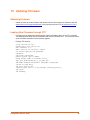
Obtaining Firmware ________________________________________________________ 95
Loading New Firmware through FTP __________________________________________ 95
16: VIP Settings
96
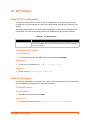
Virtual IP (VIP) Configuration ________________________________________________ 96
To Configure VIP Settings _______________________________________________96
Virtual IP (VIP) Status ______________________________________________________ 96
To View VIP Status _____________________________________________________ 96
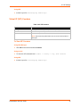
Virtual IP (VIP) Counters ____________________________________________________ 97
To View VIP Counters __________________________________________________ 97
17: Branding the PremierWave XN
98
Web Manager Customization ________________________________________________ 98
Short and Long Name Customization __________________________________________ 99
To Customize Short or Long Names _______________________________________ 99
Appendix A: Technical Support
100
Appendix B: Binary to Hexadecimal Conversions
101
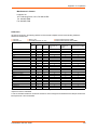
Converting Binary to Hexadecimal ___________________________________________ 101
Conversion Table _____________________________________________________ 101
Scientific Calculator ___________________________________________________ 101
Appendix C: Compliance
PremierWave XN User Guide
103
8
List of Figures
Figure 2-1 PremierWave XN Product Label ____________________________________________ 16
Figure 3-1 PremierWave XN Top/Front View ___________________________________________ 18
Figure 3-2 PremierWave XN Male DB9 DTE Serial Ports _________________________________ 18
Figure 3-3 PremierWave XN Pinout Configuration for RS-232 ______________________________ 18
Figure 3-4 PremierWave XN Pinout Configuration for Full Duplex RS-422/485 (4-wire) __________ 19
Figure 3-5 PremierWave XNXC Pinout Configuration for Half Duplex RS-422/485 (2-wire) _______ 19
Figure 3-11 PremierWave XN Bottom/Back Panel View___________________________________ 22
Figure 3-12 PremierWave XN WPS Button ____________________________________________ 22
Figure 3-13 PremierWave XN Dimensions in Millimeters (mm) _____________________________ 24
Figure 5-1 Components of the Web Manager Page ______________________________________ 29
Figure B-2 Windows Scientific Calculator _____________________________________________ 102
Figure B-3 Hexadecimal Values in the Scientific Calculator ______________________________ 102
PremierWave XN User Guide
9
List of Tables
Table 3-6 PremierWave XN LEDs and Descriptions _____________________________________ 19
Table 3-7 WLAN Signal Strength Indicator at 5 GHz _____________________________________ 20
Table 3-8 WLAN Signal Strength Indicator at 2.4 GHz ___________________________________ 20
Table 3-9 WPS Status Indicator _____________________________________________________ 20
Table 3-10 Diagnostic LED Indications _______________________________________________21
Table 6-1 Network Interface Settings _________________________________________________ 32
Table 6-2 Network 1 (eth0) Link Settings ______________________________________________ 34
Table 6-3 Network 2 (wlan0) Link Settings ____________________________________________ 35
Table 6-4 Network 2 Link Scan _____________________________________________________ 36
Table 6-5 Network 2 Link Scan Results on WebManager _________________________________ 36
Table 6-6 Network 2 Link Status ____________________________________________________ 37
Table 6-7 Creating, Deleting or Enabling WLAN Profiles __________________________________ 38
Table 6-8 WLAN Profile Basic Settings _______________________________________________39
Table 6-9 WLAN Profile Advanced Settings ___________________________________________ 40
Table 6-10 WLAN Profile Security Settings ____________________________________________ 41
Table 6-11 Additional WEP Settings for WLAN Profile. ___________________________________ 42
Table 6-12 WLAN Profile WPA and WPA2/IEEE802.11i Settings ___________________________ 43
Table 6-13 WLAN Quick Connect ___________________________________________________ 45
Table 7-1 Line Configuration Settings ________________________________________________ 46
Table 7-2 Line Command Mode Settings ______________________________________________ 47
Table 7-3 Tunnel Serial Settings ____________________________________________________ 48
Table 7-4 Tunnel Packing Mode Settings _____________________________________________ 49
Table 7-5 Tunnel Accept Mode Settings ______________________________________________ 51
Table 7-6 Tunnel Connect Mode Settings _____________________________________________ 53
Table 7-7 Tunnel Disconnect Mode Settings ___________________________________________ 54
Table 7-8 Tunnel Modem Emulation Settings __________________________________________ 55
Table 8-1 Terminal on Network and Line Settings _______________________________________ 57
Table 8-2 Host Configuration _______________________________________________________ 58
Table 9-1 DNS Settings ___________________________________________________________ 60
Table 9-2 FTP Settings ___________________________________________________________ 61
Table 9-3 Syslog Settings _________________________________________________________ 61
Table 9-4 HTTP Settings __________________________________________________________ 62
Table 9-5 HTTP Authentication Settings ______________________________________________ 64
Table 9-6 RSS Settings ___________________________________________________________ 64
Table 10-1 SSH Server Host Keys ___________________________________________________ 66
Table 10-2 SSH Client Known Hosts _________________________________________________ 67
PremierWave XN User Guide
10
Table 10-3 SSH Server Authorized Users _____________________________________________ 68
Table 10-4 SSH Client Users _______________________________________________________ 68
Table 10-5 Certificate and Key Generation Settings _____________________________________ 70
Table 10-6 Upload Certificate Settings _______________________________________________71
Table 10-7 Trusted Authority Settings ________________________________________________ 72
Table 11-1 File Display Settings ____________________________________________________ 73
Table 11-2 File Modification Settings _________________________________________________ 74
Table 11-3 File Transfer Settings ____________________________________________________ 74
Table 11-4 IP Network Stack Settings ________________________________________________ 75
Table 11-5 ICMP Network Stack Settings _____________________________________________ 76
Table 11-6 ARP Network Stack Settings ______________________________________________ 76
Table 11-7 SMTP Network Stack Settings _____________________________________________ 77
Table 11-8 Query Port Settings _____________________________________________________ 77
Table 11-9 Ping Settings __________________________________________________________ 79
Table 11-10 Traceroute Settings ____________________________________________________ 79
Table 11-11 Log Settings __________________________________________________________ 80
Table 11-12 System Settings _______________________________________________________ 82
Table 12-1 Email Configuration _____________________________________________________ 83
Table 12-2 CLI Configuration Settings ________________________________________________ 84
Table 12-3 Telnet Settings ________________________________________________________ 85
Table 12-4 SSH Settings __________________________________________________________ 85
Table 12-5 XML Exporting Configuration ______________________________________________ 86
Table 12-6 Exporting Status ________________________________________________________ 87
Table 12-7 Import Configuration from Filesystem Settings ________________________________ 88
Table 13-1 Bridge Settings _________________________________________________________ 90
Table 16-1 VIP Configuration _______________________________________________________ 96
Table 16-2 VIP Counters __________________________________________________________ 97
Table 17-1 Short and Long Name Settings ____________________________________________ 99
Table B-1 Binary to Hexadecimal Conversion _________________________________________ 101
PremierWave XN User Guide
11
1:
Using This Guide
Purpose and Audience
This guide provides the information needed to configure, use, and update the PremierWave XN. It
is intended for software developers and system integrators who are installing this product into
their designs.
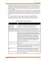
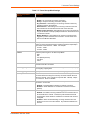
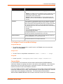
Summary of Chapters
The remaining chapters in this guide include:
Chapter
Description
2: Introduction
Main features of the product and the protocols it supports.
Includes technical specifications.
3: Installation of PremierWave XN
Instructions for installing the PremierWave XN.
4: Using DeviceInstaller
Instructions for viewing the current configuration using
DeviceInstaller.
5: Configuration Using Web Manager
Instructions for accessing Web Manager and using it to configure
settings for the device.
6: Network Settings
Instructions for configuring network settings.
7: Line and Tunnel Settings
Instructions for configuring line and tunnel settings.
8: Terminal and Host Settings
Instructions for configuring terminal and host settings.
9: Services Settings
Instructions for configuring DNS, FTP, HTTP and Syslog settings.
10: Security Settings
Instructions for configuring SSL security settings.
11: Maintenance and Diagnostics
Settings
Instructions to maintain the PremierWave, view statistics, files,
and diagnose problems.
12: Advanced Settings
Instructions for configuring email, CLI and XML settings.
13: Bridging
Instructions for bridging configuration.
14: Security in Detail
Provides additional information on security settings available.
15: Updating Firmware
Instructions for obtaining the latest firmware and updating the
PremierWave.
16: VIP Settings
Information about Virtual IP (VIP) features available on the device
and instructions on configuring settings.
17: Branding the PremierWave XN
Instructions on how to brand your device.
Appendix A: Technical Support
Instructions for contacting Lantronix Technical Support.
Appendix B: Binary to Hexadecimal
Conversions
Instructions for converting binary values to hexadecimals.
Appendix C: Compliance
Lantronix compliance information.
PremierWave XN User Guide
12
1: Using This Guide
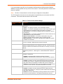
Additional Documentation
Visit the Lantronix Web site at www.lantronix.com/support/documentation for the latest
documentation and the following additional documentation.
Document
Description
PremierWave XN Command
Reference
Instructions for accessing Command Mode (the command line
interface) using a Telnet connection, SSH connection or through the
serial port. Detailed information about the commands. Also provides
details for XML configuration and status.
PremierWave XN Quick Start
Guide
Instructions for getting the PremierWave up and running.
DeviceInstaller Online Help
Instructions for using the Lantronix Windows-based utility to locate the
PremierWave and to view its current settings.
Com Port Redirector Quick Start Instructions for using the Lantronix Windows-based utility to create
and Online Help
virtual com ports.
PremierWave XN User Guide
13
2:
Introduction
PremierWave XN is a multi-port device server offering high performance, Ethernet-to-wireless
bridging connectivity that allows remote access and easy management of machines or equipment
over the network and across the internet. PremierWave XN provides bullet-proof security by
offering robust data encryption and authentication options including AES, SSH and SSL. Remote
configuration over a network is possible using Telnet, SSH, or web browser (HTTP and HTTPS).
Key Features
Power Supply: Flexible power options and input voltage range (one barrel connector for 12V
power supply, on terminal block connector for 09-30Vdc power supply).
Controller: 32-bit ARM9 microprocessor running at 400 megahertz (Mhz) with 32 KB Data
Cache and 32 Kilobytes (KB) internally based around the PremierWave EN.
Memory: 64 MB SDRAM, 64 MB NAND Flash, and 8 MB serial SPI Flash.
Ethernet: Wired 802.3 Ethernet networking
Wireless: 802.11 a/b/g/n wireless networking
Serial Ports: Two 300 to 921 kbaud, RS-232/422/485 serial ports
USB Ports: Two USB 2.0 full speed interfaces
Configuration via CLI, XML and HTTP
Ethernet to wireless tunneling
Lantronix SmartRoam technology
Built-in site survey tool
Temperature Range: Operates over a temperature range of -40°C to +70°C (-40°F to 158°F).
The storage temperature range is -40°C to 85°C (-40°F to 185°F).
Applications
The PremierWave XN device server connects serial devices such as those listed below to
Ethernet networks using the IP protocol family.
Patient Monitoring Devices
Glucose Analyzers
Infusion Pumps
Protocol Support
The PremierWave XN device server contains a full-featured IP stack. Supported protocols include:
ARP, UDP, TCP, ICMP,DHCP, Auto IP, Telnet, DNS, FTP, TFTP, SSH, SSL and Syslog for
network communications and management.
PremierWave XN User Guide
14
2: Introduction
TCP, UDP, SSH, SSL and telnet tunneling to the serial port.
TFTP for uploading/downloading files.
FTP and HTTP for firmware upgrades and uploading/downloading files.
Troubleshooting Capabilities
The PremierWave XN offers a comprehensive diagnostic toolset that lets you troubleshoot
problems quickly and easily. Available from the CLI or Web Manager, the diagnostic tools let you:
View memory and IP socket information.
Perform ping and traceroute operations.
Conduct forward or reverse DNS lookup operations.
View all processes currently running on the PremierWave XN, including CPU utilization.
View system log messages.
Configuration Methods
After installation, the PremierWave XN requires configuration. For the unit to operate correctly on
a network, it must have a unique IP address on the network. There are four basic methods for
logging into the PremierWave XN and assigning IP addresses and other configurable settings:
Web Manager: View and configure all settings easily through a web browser using the
Lantronix Web Manager. (See “Configuration Using Web Manager” on page 27.)
DeviceInstaller: Configure the IP address and related settings and view current settings on
the PremierWave XN using a Graphical User Interface (GUI) on a PC attached to a network.
You will need the latest version of DeviceInstaller. (See “Using DeviceInstaller” on page 25.)
Command Mode: There are two methods for accessing Command Mode (CLI): making a
Telnet or SSH connection, or connecting a terminal (or a PC running a terminal emulation
program) to the unit’s serial port. (See the PremierWave XN Command Reference Guide for
instructions and available commands.)
XML: The PremierWave XN supports XML-based configuration and setup records that make
device configuration transparent to users and administrators. XML is easily editable with a
standard text or XML editor. (See the PremierWave XN Command Reference Guide for
instructions and commands.)
Addresses and Port Numbers
Hardware Address
The hardware address is also referred to as the Ethernet address, physical address, or MAC
address. Sample hardware address:
00-80-A3-14-1B-18
00:80:A3:14:1B:18
PremierWave XN User Guide
15
2: Introduction
IP Address
Every device connected to an IP network must have a unique IP address. This address references
the specific unit.
Port Numbers
Every TCP connection and every UDP datagram is defined by a destination and source IP
address, and a destination and source port number. For example, a Telnet server commonly uses
TCP port number 23.
The following is a list of the default server port numbers running on the :
TCP Port 22: SSH Server (Command Mode configuration)
TCP Port 23: Telnet Server (Command Mode configuration)
TCP Port 80: HTTP (Web Manager configuration)
TCP Port 21: FTP
UDP Port 30718: LDP (Lantronix Discovery Protocol) port
TCP/UDP Port 10001: Tunnel 1 (see note below)
Note: Additional TCP/UDP ports and tunnels will be available, depending on the product
type. The default numbering of each additional TCP/UDP port and corresponding tunnel
will increase sequentially (i.e., TCP/UDP Port 1000X: Tunnel X).
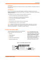
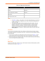
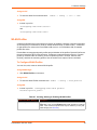
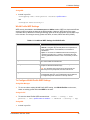
Product Information Label
The product information label on the unit contains the
following information about the specific unit:
Bar code
Product Revision
Part Number
Serial Number (MAC Address)
Manufacturing Date Code
Note: The hardware address on the
label is also the product serial number.
The hardware address on the label is the
address for the Ethernet (eth0) interface.
The WLAN (wlan0) interface uses the
Ethernet address "+1". For example, if
the product label hardware address is 0080-A3-14-1B-18, then the Ethernet
address is 00-80-A3-14-1B-18 and the
WLAN address is 00-80-A3-14-1B-19.
Figure 2-1 PremierWave XN Product Label
Bar Code
Serial Number
Part Number
Revision
Country of Origin
& Manufacture
Manufacturing
Date Code
PremierWave XN User Guide
16
3:
Installation of PremierWave XN
This chapter describes how to install the PremierWave XN device server. It contains the following
sections:
Package Contents
User-Supplied Items
Hardware Components
Wi-Fi Protected Setup (WPS)
Installing the PremierWave XN
Package Contents
The PremierWave XN package includes the following items:
One PremierWave XN device
One Power Supply 12 VDC with international adapters
Two External Antenna, RPSMA Connector
One RJ-45 Ethernet Straight Cat5 Cable, 1.5 meter
Quick Start Guide
User-Supplied Items
To complete your installation, you need the following items:
RS-232/422/485 serial devices that require network connectivity.
A serial cable, as listed below, for each serial device. One end of the cable must have a
female DB9 connector for the serial port.
-
A null modem cable to connect the serial port to another DTE device.
-
A straight-through modem cable to connect the serial port to a DCE device.
An available connection to your Ethernet network and an Ethernet cable.
A working AC power outlet if the unit will be powered from an AC power adapter.
Hardware Components
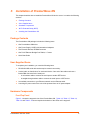
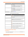
Front/Top Panel
Figure 3-1 shows the top panel view of the PremierWave XN. Table 3-6, Table 3-7, Table 3-8,
Table 3-9 and Table 3-10 list and explain the behavior of the LEDs on the top panel.
PremierWave XN User Guide
17
3: Installation of PremierWave XN
Figure 3-1 PremierWave XN Top View
Signal
Strength
LEDs
WPS
Button
(pin hole)
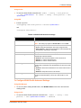
The PremierWave XN has two male DB9 serial ports that support RS-232/422/485. Figure 3-2
shows the front view of the device. The default serial port settings are 9600 baud, 8 bits, no parity,
1 stop bit, no flow control.
Figure 3-2 PremierWave XN Male DB9 DTE Serial Ports
2 USB
Ports
Reset
Button
Serial 1
Serial 2
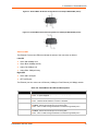
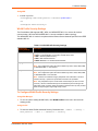
Figure 3-3 PremierWave XN Pinout Configuration for RS-232
PremierWave XN User Guide
18
3: Installation of PremierWave XN
Figure 3-4 PremierWave XN Pinout Configuration for Full Duplex RS-422/485 (4-wire)
Figure 3-5 PremierWave XN Pinout Configuration for Half Duplex RS-422/485 (2-wire)
Ethernet LEDs
The Ethernet Port has two LEDs that indicate the status of the connection as follows:
Left LED
Green ON 100Mbps Link
Green Blink 100Mbps Activity
Amber ON 10Mbps Link
Amber Blink 10Mbps Activity
Right LED
Green ON Full Duplex
OFF Half Duplex
The Ethernet port can connect to an Ethernet (10 Mbps) or Fast Ethernet (100 Mbps) network.
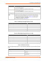
Table 3-6 PremierWave XN LEDs and Descriptions
LED
Description
Power
WLAN
Serial 1
Serial 2
PremierWave XN User Guide
GREEN - displays a solid light when power is properly supplied.
OFF - no power supplied.
AMBER - flashes when the RX/TX packets are detected on the WLAN interface.
OFF - indicates WLAN interface is inactive or disabled.
GREEN - flashes when Serial port 2 is transmitting data.
AMBER - flashes when Serial port 2 is receiving data.
OFF - when no data is being transmitted or received through Serial port 2.
GREEN - flashes when Serial port 2 is transmitting data.
AMBER - flashes when Serial port 2 is receiving data.
OFF - when no data is being transmitted or received through Serial port 2.
19
3: Installation of PremierWave XN
LED (continued)
Description
USB 1
USB 2
GREEN - displays a solid light when a USB device is connected to USB 1 Host port
and is functioning properly.
OFF- when no USB device is connected to USB 1 Host port.
GREEN - displays a solid light when a USB device is connected to USB 2 Host port
and is functioning properly.
OFF- when no USB device is connected to USB 2 Host port.
Fault/Diagnostic
See Table 3-10 for diagnostic indications.
Signal Strength
LEDs
Indicates WLAN signal strength when connection is established. During WPS
negotiation and connection establishment, it reports status of WPS transaction.
When indicating the WLAN signal strength, see Table 3-7 for signal strength
information for connections in 5 GHz band or Table 3-8 for signal strength
information for connections in 2.4 GHz band.
For WPS status indications, see Table 3-9.
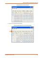
Table 3-7 WLAN Signal Strength Indicator at 5 GHz
Signal Strength
Color & Number of LED Signal Bars
Greater than or equal to -60 dBm
5 Green
Greater than or equal to -62 dBm and less than -60 dBm
4 Green
Greater than or equal to -65 dBm and less than -62 dBm
3 Green
Greater than or equal to -68 dBm and less than -65 dBm
2 Amber
Greater than or equal to -70 dBm and less than -68 dBm
1 Amber
Less than -70 dBm
All Off
Table 3-8 WLAN Signal Strength Indicator at 2.4 GHz
Signal Strength
Color & Number of LED Signal Bars
Greater than or equal to -60 dBm
5 Green
Greater than or equal to -67 dBm and less than -60 dBm
4 Green
Greater than or equal to -73 dBm and less than -67 dBm
3 Green
Greater than or equal to -98 dBm and less than -73 dBm
2 Amber
Greater than or equal to -110 dBm and less than -98 dBm
1 Amber
Less than -110 dBm
All Off
Table 3-9 WPS Status Indicator
When the signal strength indicator is used to indicate the WPS status, only one amber LED will be
used.
WPS Status
Blink Pattern
WPS is enabled and on
Short, continuous
WPS has a profile error
Long, long, long, short, short, 2 seconds off,
continuous
WPS has a timeout error
Long, long, long, short, short, short, short, 2 seconds
off, continuous
PremierWave XN User Guide
20
3: Installation of PremierWave XN
Table 3-10 Diagnostic LED Indications
Fault Conditions
Blink Pattern
No Ethernet link when eth0 is enabled
Long, long, short, short, 2 seconds off, continuous
No WLAN link (no BSSID detected) when wlan0 is
enabled
Long, long, long, short, short, 2 seconds off,
continuous
No IP obtained from WLAN when wlan0 is enabled
and the bridge mode is disabled.
Long, long, long, short, short, short, 2 seconds off,
continuous
Over temperature or when the internal temperature
reaches 85°F.
Long, short, short, short, 2 seconds off, continuous
Loss of power or when both the terminal and barrel
power input is below 9 volts.
Long, short, short, 2 seconds off, continuous
Notes:
For Table 3-10 above, a “long” blink is 0.7 seconds of light followed by 0.3 seconds of
no light. A “short” blink is a light that is on for only 0.2 seconds and followed by 0.2
seconds of no light.
The diagnostic blink patterns reflect the highest priority fault condition. Also, the
Diagnostic LED will give an initial, identifying blink pattern to indicate the type of
diagnostic information it will display. All power and other non-network related
diagnostic patterns begin with one long blink. All wired LAN related diagnostics
patterns begin with two long blinks. All WLAN related diagnostics patterns begin with
three long blinks.
Reset Button
You can reset the PremierWave XN to factory defaults, including clearing the network settings.
The IP address, gateway, and netmask are set to 00s. To reset the unit to factory defaults, perform
the following steps.
1. Place the end of a paper clip or similar object into the reset opening (see Figure 3-11) and
press and hold down micro switch during a power cycle for a minimum of 10-15 seconds.
2. Remove the paper clip to release the button. The unit will continue the boot process restoring
it back to the original factory default settings.
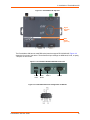
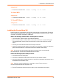
Back Panel
On the PremierWave XN is a Power 1 Plug, 3-Pin Terminal Connector for Backup Power, and RJ45 Ethernet port as shown in Figure 3-11.
PremierWave XN User Guide
21
3: Installation of PremierWave XN
Figure 3-11 PremierWave XN Bottom/Back Panel View
VV+
Antenna
Terminal
Block
Power
(3-pin)
Barrel
Plug
Power
Ethernet
Antenna
Wi-Fi Protected Setup (WPS)
Using WPS, you have the option of connecting to PremierWave devices with a router or access
point in a single operation instead of manually creating a profile with a network name (SSID),
setting up wireless security parameters and updating the choice list.
Figure 3-12 PremierWave XN WPS Button
WPS Button
(pin hole opening)
To Start WPS
Using the Device
1. Place the end of a paper clip or similar object into the WPS opening (see Figure 3-12) and
press and hold down for a minimum of 5 seconds.
2. Remove the paper clip to release the button. The unit will start Wi-Fi Protected Setup.
PremierWave XN User Guide
22
3: Installation of PremierWave XN
Using the CLI
To enter the command level:
enable -> config -> if 2 -> link
To Cancel WPS
Using the CLI
To enter the command level:
enable -> config -> if 2 -> link
To Show WPS Status
Using the CLI
To enter the command level:
enable -> config -> if 2 -> link
Installing the PremierWave XN
Be sure to place or mount the device securely on a flat horizontal or vertical surface. The device
comes with mounting brackets for mounting the device vertically, for example on a wall. If using
AC power, avoid outlets controlled by a wall switch.
Observe the following guidelines when connecting the serial devices:
The PremierWave XN serial ports support RS-232/422/485.
The null modem cable is the best cable to connect the serial device to another DTE device.
The straight-though (modem) cable is the best cable to connect the serial port to a DCE
device.
Connect your RJ-45 Ethernet cable to the RJ-45 port of the unit.
The device supports a power range of 9 to 30 VDC. You can power up the device with barrelpower connector and/or the 3 pin terminal connector for backup power supply.
Note: As soon as you plug the device into power, the device powers up automatically,
the self-test begins, and LEDs would indicate the device's status
Perform the following steps to install your device:
1. Connect devices to the serial ports.
2. Connect a RJ-45 Ethernet cable between the unit and your Ethernet network.
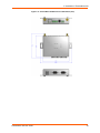
3. Connect the Antennas to the SMA connector on the side. Do note that the safe distance due to
RF exposure from antenna is 23cm.
Note: Antennas must be installed prior to powering on the unit. Do not remove or
connect the antennas while the unit power is on.
4. Plug the PremierWave XN into the power outlet by using the included power supply.
PremierWave XN User Guide
23
3: Installation of PremierWave XN
Figure 3-13 PremierWave XN Dimensions in Millimeters (mm)
PremierWave XN User Guide
24
4:
Using DeviceInstaller
This chapter covers the steps for locating a PremierWave XN unit and viewing its properties and
device details. DeviceInstaller is a free utility program provided by Lantronix that discovers,
configures, upgrades and manages Lantronix Device Servers.
Notes:
For instructions on using DeviceInstaller to configure the IP address and related
settings or for more advanced features, see the DeviceInstaller Online Help.
Auto IP generates a random IP address in the range of 169.254.0.1 to
169.254.255.254, with a netmask of 255.255.0.0, if no BOOTP or DHCP server is
found. These addresses are not routable.
Accessing PremierWave XN Using DeviceInstaller
Note: Make note of the MAC address. It is needed to locate the PremierWave XN using
DeviceInstaller.
To use the DeviceInstaller utility, first install the latest version from the downloads page on the
Lantronix web site www.lantronix.com/downloads.
1. Run the executable to start the installation process and respond to the installation wizard
prompts. (If prompted to select an installation type, select Typical.)
2. Click Start -> All Programs -> Lantronix -> DeviceInstaller -> DeviceInstaller.
3. When DeviceInstaller starts, it will perform a network device search. To perform another
search, click Search.
4. Expand the PremierWave XN folder by clicking the + symbol next to the folder icon. The list of
available Lantronix PremierWave XN devices appears.
5. Select the PremierWave XN unit by expanding its entry and clicking on its IP address to view
its configuration.
6. On the right page, click the Device Details tab. The current PremierWave XN configuration
appears. This is only a subset of the full configuration; the full configuration may be accessed
via Web Manager, CLI or XML.
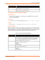
Device Detail Summary
Note:
The settings are Display Only in this table unless otherwise noted
Current Settings
Description
Name
Name identifying the PremierWave.
DHCP Device Name
The name associated with the PremierWave’s current IP address, if the
IP address was obtained dynamically.
PremierWave XN User Guide
25
4: Using DeviceInstaller
Current Settings (continued)
Description
Group
Configurable field. Enter a group to categorize the PremierWave.
Double-click the field, type in the value, and press Enter to complete.
This group name is local to this PC and is not visible on other PCs or
laptops using DeviceInstaller.
Comments
Configurable field. Enter comments for the PremierWave. Double-click
the field, type in the value, and press Enter to complete. This description
or comment is local to this PC and is not visible on other PCs or laptops
using DeviceInstaller.
Device Family
Shows the PremierWave device family type as “PremierWave”.
Type
Shows the device type as “PremierWave”.
ID
Shows the PremierWave ID embedded within the unit.
Hardware Address
Shows the PremierWave hardware (MAC) address.
Firmware Version
Shows the firmware currently installed on the PremierWave.
Extended Firmware Version
Provides additional information on the firmware version.
Online Status
Shows the PremierWave status as Online, Offline, Unreachable (the
PremierWave is on a different subnet), or Busy (the PremierWave is
currently performing a task).
IP Address
Shows the PremierWave current IP address. To change the IP address,
click the Assign IP button on the DeviceInstaller menu bar.
Appears “Dynamically” if the PremierWave automatically received an IP
address (e.g., from DHCP). Appears “Statically” if the IP address was
configured manually.
IP Address was Obtained
If the IP address was assigned dynamically, the following fields appear:
Subnet Mask
Gateway
Obtain via DHCP with values of True or False.
Obtain via BOOTP with values of True or False.
Shows the subnet mask specifying the network segment on which the
PremierWave resides.
Shows the IP address of the router of this network.
There is no default.
Number of Ports
Shows the number of serial ports on this PremierWave.
Supports Configurable Pins
Shows False, indicating configurable pins are not available on the
PremierWave XN.
Supports Email Triggers
Shows True, indicating email triggers are available on the PremierWave.
Telnet Supported
Indicates whether Telnet is enabled on this PremierWave.
Telnet Port
Shows the PremierWave port for Telnet sessions.
Web Enabled
Indicates whether Web Manager access is enabled on this
PremierWave.
Web Port
Shows the PremierWave port for Web Manager configuration (if Web
Enabled field is True).
Firmware Upgradable
Shows True, indicating the PremierWave firmware is upgradable as
newer versions become available.
PremierWave XN User Guide
26
5:
Configuration Using Web Manager
This chapter describes how to configure PremierWave XN using Web Manager, the Lantronix
browser-based configuration tool. The unit’s configuration is stored in nonvolatile memory and is
retained without power. All changes take effect immediately, unless otherwise noted. It contains
the following sections:
Accessing Web Manager
Web Manager Components
Navigating Web Manager
Accessing Web Manager
Note: You can also access the Web Manager by selecting the Web Configuration tab on
the DeviceInstaller window.
To access Web Manager, perform the following steps:
1. Open a standard web browser. Lantronix supports the latest version of Internet Explorer,
Mozilla Suite, Mozilla Firefox, Safari, Chrome or Opera.
2. Enter the IP address or hostname of the PremierWave XN in the address bar. The IP address
may have been assigned manually using DeviceInstaller (see the PremierWave XN Quick
Start Guide) or automatically by DHCP.
3. Enter your username and password.The factory-default username is “admin” and the
password is “PASS”. The Device Status web page displays configuration, network settings,
line settings, tunneling settings, and product information.
Note: The Logout button is available on any web page. Logging out of the web page
would force re-authentication to take place the next time the web page is accessed.
PremierWave XN User Guide
27
5: Configuration Using Web Manager
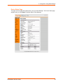
Device Status Page
The page is the first page that appears after you log into Web Manager. The Device Status page
appears when you click Status in the Main Menu in Web Manager.
PremierWave XN User Guide
28
5: Configuration Using Web Manager
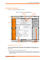
Web Manager Components
The layout of a typical Web Manager page is below.
Figure 5-1 Components of the Web Manager Page
Items to
configure
Links to
subpages
Header
Menu Bar
Footer
Configuration and/or Status Area
Information
and Help Area
Web Manager pages have these sections:
The menu bar always appears at the left side of the page, regardless of the page shown. The
menu bar lists the names of the pages available in the Web Manager. To bring up a page, click it in
the menu bar.
The main area of the page has these additional sections:
Links near the top of many pages, such as the one in the example above, enable you to link to
additional subpages. On some pages, you must also select the item you are configuring, such
as a line or a tunnel.
PremierWave XN User Guide
29
5: Configuration Using Web Manager
In the middle of many pages, you can select or enter new configuration settings. Some pages
show status or statistics in this area rather than allow you to enter settings.
At the bottom of most pages, the current configuration is displayed. In some cases, you can
reset or clear a setting.
The information or help area shows information or instructions associated with the page.
A Logout link is available at the upper right corner of every page. In Chrome or Safari, it is
necessary to close out of the browser to completely logout. If necessary, reopen the browser
to log back in.
The footer appears at the very bottom of the page. It contains copyright information and a link
to the Lantronix home page.
Navigating Web Manager
The Web Manager provides an intuitive point-and-click interface. A menu bar on the left side of
each page provides links you can click to navigate from one page to another. Some pages are
read-only, while others let you change configuration settings.
Note: There may be times when you must reboot the PremierWave XN for the new
configuration settings to take effect. The chapters that follow indicate when a change
requires a reboot. Anytime you reboot the unit, this operation will take some time to
complete. Please wait a minimum of 10-20 seconds after rebooting the unit before
attempting to make any subsequent connections.
Web Manager Page
Description
See
Page
Status
Shows product information and network, line, and tunneling settings.
28
Bridge
Allows you to configure a bridge and shows the current operational state of
the bridge.
89
CLI
Shows Command Line Interface (CLI) statistics and lets you change the
current CLI configuration settings.
84
Diagnostics
Lets you perform various diagnostic procedures.
78
DNS
Shows the current configuration of the DNS subsystem and the DNS cache.
60
Email
Shows email statistics and lets you clear the email log, configure email
settings, and send an email.
83
Filesystem
Shows file system statistics and lets you browse the file system to view a file, 73
create a file or directory, upload files using HTTP, copy a file, move a file, or
perform TFTP actions.
FTP
Shows statistics and lets you change the current configuration for the File
Transfer Protocol (FTP) server.
61
Host
Lets you view and change settings for a host on the network.
58
HTTP
Shows HyperText Transfer Protocol (HTTP) statistics and lets you change the 62
current configuration and authentication settings.
Line
Shows statistics and lets you change the current configuration and Command 46
mode settings of a serial line.
Network
Shows status and lets you configure the network interface.
PremierWave XN User Guide
32
30
5: Configuration Using Web Manager
Web Manager Page
(continued)
Description
See
Page
Protocol Stack
Lets you perform lower level network stack-specific activities.
75
Query Port
Lets you change configuration settings for the query port.
77
RSS
Lets you change current Really Simple Syndication (RSS) settings.
64
SmartRoam
Lets you configure SmartRoam options through Network Link Settings.
34
SSH
Lets you change the configuration settings for SSH server host keys, SSH
server authorized users, SSH client known hosts, and SSH client users.
66
SSL
Lets you upload an existing certificate or create a new self-signed certificate.
69
Syslog
Lets you specify the severity of events to log and the server and ports to
which the syslog should be sent.
61
System
Lets you reboot device, restore factory defaults, upload new firmware, and
change the device long and short names.
82
Terminal
Lets you change current settings for a terminal.
57
Tunnel
Lets you change the current configuration settings for a tunnel.
48
VIP
Lets you configure Virtual IP addresses to be used in Tunnel Accept Mode
and Tunnel Connect Mode.
96
WLAN Profiles
Lets you view, edit, delete and create a WLAN profile on a device.
38
XML
Lets you export XML configuration and status records, and import XML
configuration records.
86
PremierWave XN User Guide
31
6:
Network Settings
The Network Settings show the status of the Ethernet or WLAN interface/link and let you configure
the settings on the device. Interface settings are related to the configuration of the IP and related
protocols. Link settings are related to the physical link connection, which carries the IP traffic.
The PremierWave XN contains two network interfaces. Only one interface may be active at a
time; however, if bridging is enabled, both interfaces will be activated and controlled by the
bridging subsystem.The Ethernet interface is also called interface 1 or eth0, and the WLAN
interface is called interface 2 or wlan0.
Notes:
Some settings require a reboot to take effect. These settings are noted below.
Wait a minimum of 10-20 seconds after rebooting the unit before attempting to make
any subsequent connections.
The blue text in the XML command strings of this chapter are to be replaced with a
user-specified name.
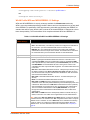
Network Interface Settings
Table 6-1 shows the network interface settings that can be configured.
These settings apply to both the Ethernet (eth0) and WLAN (wlan0) interfaces, but are configured
independently for each interface.
Table 6-1 Network Interface Settings
Network Interface
Settings
Description
State
Enables or disables the interface.
BOOTP Client
Select to turn On or Off. At boot up, after the physical link is up, the
PremierWave will attempt to obtain IP settings from a BOOTP server.
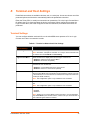
Note: Overrides the configured IP address/mask, gateway, hostname, and
domain. When DHCP is Enabled, the system automatically uses DHCP,
regardless of whether BOOTP is Enabled. Changing this value requires you to
reboot the device.
DHCP Client
Select to turn On or Off. At boot up, after the physical link is up, the
PremierWave will attempt to obtain IP settings from a DHCP server and will
periodically renew these settings with the server.
Note: Overrides BOOTP, the configured IP address/mask, gateway,
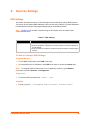
hostname, and domain. Changing this value requires you to reboot the device.
Note: Within WebManager, click Renew to renew the DHCP lease.
PremierWave XN User Guide
32
6: Network Settings
Network Interface
Settings (continued)
Description
IP Address
Enter the static IP address to use for the interface. You may enter it alone or in
CIDR format.
Note: This setting will be used if Static IP is active (both DHCP and BOOTP
are Disabled). Changing this value requires you to reboot the device. When
DHCP or BOOTP is enabled, the PremierWave XN tries to obtain an IP address
from a DHCP or BOOTP server. If it cannot, the PremierWave XN generates
and uses an Auto IP address in the range of 169.254.xxx.xxx, with a network
mask of 255.255.0.0.
Default Gateway
Enter the IP address of the router for this network.
Note: This setting will be used if Static IP is active (both DHCP and BOOTP
are Disabled).
Hostname
Enter the hostname for the interface. It must begin with a letter or number,
continue with a sequence of letters, numbers, or hyphens, and end with a letter
or number.
Note: This setting will take effect immediately, but will not register the
hostname with a DNS server until the next reboot.
Domain
Enter the domain name suffix for the interface.
Note: This setting will be used when either Static IP or Auto IP is active, or if
DHCP/BOOTP is active and no Domain Suffix was acquired from the server.
DHCP Client ID
Enter the ID if the DHCP server requires a DHCP Client ID option. The DHCP
server’s lease table shows IP addresses and MAC addresses for devices. The
lease table shows the Client ID, in hexadecimal notation, instead of the
PremierWave XN MAC address.
Primary DNS
Enter the IP address of the primary Domain Name Server.
Note: This setting will be used when either Static IP or Auto IP is active, or if
DHCP/BOOTP is active and no DNS server was acquired from the server.
Secondary DNS
Enter the IP address of the secondary Domain Name Server.
Note: This setting will be used when either Static IP or Auto IP is active, or if
DHCP/BOOTP is active and no DNS server was acquired from the server.
MTU
When DHCP is enabled, the MTU size is (usually) provided with the IP address.
When not provided by the DHCP server, or using a static configuration, this
value is used. The MTU size can be from 576 to 1500 bytes, the default being
1500 bytes.
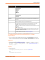
To Configure Network Interface Settings
Using Web Manager
To modify Ethernet (eth0) settings, click Network on the menu and select Network 1 ->
Interface -> Configuration.
To modify Wireless (wlan0) settings, click Network on the menu and select Network 2 ->
Interface -> Configuration.
Using the CLI
To enter the eth0 command level: enable -> config -> if 1
To enter the wlan0 command level:
PremierWave XN User Guide
enable -> config -> if 2
33
6: Network Settings
Using XML
Include in your file: <configgroup name="interface" instance="eth0">
Include in your file: <configgroup name="interface" instance="wlan0">
To View Network Interface Status
Using Web Manager
In Network Interface Status, you can view both the current operational settings as well as the
settings that would take affect upon a device reboot.
To view Ethernet (eth0) Status, click Network on the menu and select Network 1 ->
Interface -> Status.
To view Wireless (wlan0) Status, click Network on the menu and select Network 2 ->
Interface -> Status.
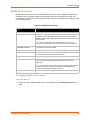
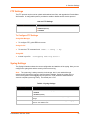
Network Link Settings
Physical link parameters can be configured for an Ethernet (eth0) Network Interface (see
Table 6-2) and a WLAN (wlan0) Network Interface (see Table 6-3).
Table 6-2 Network 1 (eth0) Link Settings
Network 1 Ethernet (eth0)
Link Settings
Description
Speed
Select the Ethernet link speed. (Default is Auto)
Duplex
Auto = Auto-negotiation of Link Speed
10 Mbps = Force 10 Mbps
100 Mbps = Force 100 Mbps
Select the Ethernet link duplex mode. (Default is Auto)
Auto = Auto-negotiation of Link Duplex
Half = Force Half Duplex
Full = Force Full Duplex
Notes:
When speed is Auto, duplex must be Auto or Half.
When speed is not Auto, duplex must be Half or Full.
Fixed speed Full duplex will produce errors connected to Auto, due to duplex
mismatch.
SmartRoam
SmartRoam monitors the signal strengths of all in-range access points belonging to the Extended
Service Set (ESS) to which the PremierWave is currently connected. When an AP is found with a
signal strength which is significantly greater than that of the currently associated AP, SmartRoam
automatically switches to the new AP. This reduces interruptions in wireless connectivity and
ensures optimal signal strength. Roaming happens automatically and is completely transparent to
the user; no loss of network connectivity should occur.
PremierWave XN User Guide
34
6: Network Settings
SmartRoam periodically scans for access points which belong to the current ESS (having the
same SSID and security settings at the currently associated AP.) The results are then searched
for an AP with a 'stronger' signal (higher RSSI) than the current AP. If the search is successful,
SmartRoam triggers a disconnection from the current AP and a connection to the one selected
from the scan results.
Since moving between access points are a time-consuming process which can negatively impact
throughput, SmartRoam employs a delta value to ensure that the move only occurs if there would
be a significant gain in signal strength. When searching the results of a scan, SmartRoam only
considers those APs whose RSSI exceeds that of the currently associated AP by at least the delta
value.
Note: RSSI is reported in two different ways: when accessed through WebManager,
you will be given the value of a single, instantaneous sample versus when you access the
RSSI roaming state through the CLI, where the RSSI value given is averaged over time.
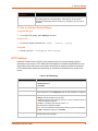
Table 6-3 Network 2 (wlan0) Link Settings
Network 2 WLAN (wlan0)
Link Settings
Description
Choice 1 Profile
Choice 2 Profile
Choice 3 Profile
Select up to four (4) WLAN Profiles for automatic connection to wireless
networks. More information on wireless settings is available in the
section, To Configure Network Link Settings on page 36.
Enter the name of the WLAN Profile desired for each choice.
Choice 4 Profile
Out of Range Scan Interval Set the amount of time in seconds, between SmartRoaming scans.
Roaming
Click to Enable or Disable SmartRoaming.
RSSI Delta
The minimum difference (in dBm) between the current RSSI and the RSSI
of any access point in the scan results before it will be considered as a
roaming candidate. The configured value will actually be used for the highpower delta. The roaming delta is cut in half for RSSI below -50dBm. The
value for the low-power delta will be derived from the configured one by
dividing it by two. Default value: 24dBm, range: 14 - 24dBm. When
searching the results of a scan, SmartRoam only considers those APs
whose RSSI exceeds that of the currently associated AP by at least the
delta value. Since moving between access point is a time-consuming
process which can negatively impact throughput, SmartRoam employs a
delta value to ensure that the move only occurs if there would be a
significant gain in signal strength.
Debugging Level
Set the verbosity level for printing WLAN Link messages to the TLOG
(Default is Info).
Active Channel Scan Time
Set the amount of time, in milliseconds, the radio will dwell on each
individual channel when performing an active scan. During active scanning,
the radio transmits probe requests and gathers probe responses from other
devices. The range of values is 50 to 150 msec.
Passive Channel Scan
Time
Set the amount of time, in milliseconds, the radio will dwell on each
individual channel when performing a passive scan. During passive
scanning the radio does not transmit probe requests, instead relying on
beacons sent by other devices. The range of values is 100 to 400 msec.
Radio Band Selection
Select the band(s) on which the radio will operate. Options are 2.4 GHz
only, 5 GHz only or Dual band.
PremierWave XN User Guide
35
6: Network Settings
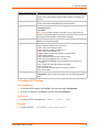
To Configure Network Link Settings
Using Web Manager
To modify Ethernet (eth0) Link information, click Network on the menu and select Network 1
-> Link.
To modify Wireless (wlan0) Link information, click Network on the menu and select Network
2 -> Link -> Configuration.
Using the CLI
To enter the eth0 Link command level: enable -> config -> if 1 -> link
To enter the wlan0 Link command level: enable -> config -> if 2 -> link
enable -> config -> if 2 -> link -> choice 1|2|3|4
or
Using XML
Include in your file: <configgroup name="ethernet" instance="eth0">
Include in your file: <configgroup name="wlan" instance="wlan0">
WLAN Link Status and Scan Commands
These commands display information about the current state of the wireless network.
Table 6-4 Network 2 Link Scan
WLAN Link Information
Commands
Description
Scan “<network SSID>”
Perform a scan for devices within range of the PremierWave XN. Including the
optional network SSID limits the scan to devices configured with the specified
network SSID. Omitting the network SSID performs a scan for all devices in
range.
Note: When omitting the network SSID it is still necessary to include the
opening and closing quotation marks (scan “”). When the PremierWave is
associated with an access point, scanning is only preformed on the band on
which the unit is connected.
Refresh scan results
every 15 seconds
(checkbox)
Check this to auto update the list of networks every 15 seconds.
Uncheck this to stop auto update.
The results of the scan command are presented in the following format in the table below:
Table 6-5 Network 2 Link Scan Results on WebManager
WLAN Link Scan Results Field
Description
Network Name
The Service Set Identifier (network name) of the device.
BSSID
Basic Service Set Identifier.
Ch/Channel
The channel on which the device is operating.
PremierWave XN User Guide
36
6: Network Settings
WLAN Link Scan Results Field
Description
RSSI
The instantaneous Received Signal Strength Indicator (RSSI) of the
device measured in dBm.
Note: RSSI reported in scan results is a single sampling, while the
RSSI reported in the 'status' command (showing the signal strength of
the currently connected AP) is averaged over time.
Security Suite
Indicates the security suite in use by the device as well as whether it is
operating in Adhoc (IBSS) mode.
The results of the status command are presented in the following format:
Table 6-6 Network 2 Link Status
WLAN Link Status
Description
Connection State
Indicates the connection state.
BSSID
A unique identifier for the Basic Service Set corresponding to the
MAC address of the Access Point in infrastructure mode, or a
generated value in Adhoc mode.
SSID
The Service Set Identifier of the connected network.
Topology
The type of wireless network in use for the current association
(Adhoc or Infrastructure).
Active WLAN Profile
Indicates which WLAN profile created the current connection to
the wireless network.
Pairwise Cipher
The standard used to encrypt a particular type of data in the
current wireless association.
Group Cipher
The standard used to encrypt a particular type of data in the
current wireless association.
Authentication
Indicates the method of distributing encryption key material.
Security Suite
Indicates the security suite used for the current association.
Channel
The channel used for the current association.
IP Address
The IP address assigned to the PremierWave.
RSSI
A measure of the power level of the received radio signal in dBm,
specifically the RSSI of the currently associated AP averaged
over time.
Note: RSSI reported in scan results is a single sampling, while
the RSSI reported in the 'status' command (showing the signal
strength of the currently connected AP) is averaged over time.
WPS Mode
Indicates whether WPS is activated.
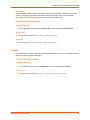
To View WLAN Link Scan and Status Information
Using Web Manager
To scan the Wireless (wlan0) Link, click Network in the menu and select Network 2 -> Link > Scan.
To view the Wireless (wlan0) Link status information, click Network in the menu and select
Network 2 -> Link -> Status.
PremierWave XN User Guide
37
6: Network Settings
Using the CLI
To enter the wlan0 Link command level:
enable -> config -> if 2 -> link
Using XML
Include in your file:
<statusgroup name="wlan status">
and
<statusgroup name="wlan scan">
WLAN Profiles
A WLAN profile defines all of the settings necessary to establish a wireless connection with either
an access point (in infrastructure mode) or another wireless client (in Adhoc mode.) A maximum
of eight profiles can exist on the PremierWave XN at a time. In PremierWave XN, all enabled
profiles are active.
PremierWave now supports dynamic profiles and prioritization of the profiles. Dynamic Profiles are
the ones created via WPS or QuickConnect. Profiles are numbered based on priority. Dynamic
profiles (in reversed order of creation), choice list profiles (Choice1, Choice2, Choice3, and
Choice4), and then the remaining profiles. Use the number from output of 'show' command.
To Configure WLAN Profiles
You can view, edit, create or delete a WLAN profile.
Using WebManager
Click WLAN Profiles on the menu.
Using the CLI
To enter the wlan0 Profile command level: enable -> config -> wlan profiles
Using XML
Include in your file: <configgroup name="wlan profile"
instance="profile_name">
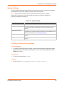
Table 6-7 Creating, Deleting or Enabling WLAN Profiles
WLAN Profile Basic Settings
Description
Create new profile
Type in the name of the new profile to be created into the Create new
profile field. Then, click the Submit button which appears to create the
profile. Once created, the profile name may be clicked so you may edit
profile settings (see Table 6-8).
PremierWave XN User Guide
38
6: Network Settings
WLAN Profile Basic Settings
Description
Delete (checkbox)
Click the Delete checkbox beside the profile(s) to be deleted. Three
buttons will appear:
Enabled (checkbox)
Click the Submit button to permanently delete profile(s).
Click the Apply button to delete the profile for testing purposes. If the
device reboots, this change will not be applied.
Click the Cancel button to cancel this action, as desired.
Click the Enabled checkbox beside the profile(s) to be enabled. Three
buttons will appear:
WLAN Profile
Click the Submit button to permanently enable profile(s).
Click the Apply button to enable the profile for testing purposes. If the
device reboots, this change will not be applied.
Click the Cancel button to cancel this action, as desired.
Click on a specific WLAN Profile name to edit the WLAN profile basic
settings (see Table 6-8).
(link to specific profile)
Table 6-8 WLAN Profile Basic Settings
WLAN Profile Basic Settings
Description
Network Name (SSID)
Specify the name of the wireless network (SSID.)
Warning:
Creating a new profile with a pre-existing network
name will cause the original network name and associated profile
to be overwritten.
State
Select to Enable or Disable.
Topology
Specify Infrastructure (ESS) or Adhoc (IBSS) mode.
Channel
Infrastructure: mode that communicates with access points.
Adhoc: mode that communicates with other clients.
Specify the channel for an Adhoc network.
Note: This setting only applies to the creation of an Adhoc network.
Scan 2.4 GHz Band
Select to Enable or Disable scanning for a WLAN profile on the 2.4 GHz
band.
Note: Setting this value to “Disabled” prevents this profile from
connecting to any device operating in the 2.4 GHz band.
Scan 5 GHz Band
Select to Enable or Disable scanning for a WLAN profile on the 5 GHz
band.
Note: Setting this value to “Disabled” prevents this profile from
connecting to any device operating in the 5 GHz band.
Scan DFS Channels
Select to Enable or Disable scanning on the DFS (Dynamic Frequency
Selection) channels in the 5 GHz band.
Note: This setting only applies if scanning in the 5 GHz band is enabled.
To Configure WLAN Profile Basic Settings
Using Web Manager
To view or edit an existing WLAN profile or to create a new profile, click WLAN Profiles on the
menu and select an existing profile.
PremierWave XN User Guide
39
6: Network Settings
Using the CLI
To enter the wlan0 Profile command level: enable -> config -> wlan profiles
-> edit <profile number>
or enable -> config -> wlan profiles -> edit
<profile name>
Using XML
Include in your file:
<configgroup name=”wlan profile” instance=”profile name”>
and
<configitem name=”basic”>
Table 6-9 WLAN Profile Advanced Settings
WLAN Profile Advanced Settings Description
TX Data Rate Maximum
Specify the rate for data transmission.
Note: This setting only applies if ‘TX Data Rate’ is set to ‘Fixed’.
TX Data Rate
Specify the type of transmission data rate:
Fixed = keeps the transmission rate at the configured value.
Auto-reduction = allows the PremierWave to reduce the data rate
automatically, depending on link quality.
TX Power Maximum
Specify the maximum transmission output power in dBm.
Antenna Diversity
Select the antenna the radio will use or allow PremierWave XN to
automatically make the selection.
Power Management
Select to Enable or Disable power management, which reduces the
overall power consumption of the PremierWave unit, but can increase
latency.
Power Management Interval
Enabled = allow the PremierWave to select the antenna.
Antenna 1 = use the internal antenna.
Antenna 2 = use the external antenna.
Enabled = allows the PremierWave to turn off the receiver when it
is idling.
Disabled = keeps the receiver on at all times.
Select number of beacons (100 msec interval) between 1 and 10.
The above-mentioned latency can be up to this number “X” 100
msec.
To Configure WLAN Profile Advanced Settings
Using Web Manager
To view or edit an existing WLAN Profile, click WLAN Profiles on the menu and select an
existing profile.
Using the CLI
To enter the wlan0 Profile Advanced command level: enable -> config -> wlan
profiles -> edit <profile name or number> -> advanced
PremierWave XN User Guide
40
6: Network Settings
Using XML
Include in your file:
<configgroup name=”wlan profile” instance=”profile name”>
and
<configitem name=”security”>
WLAN Profile Security Settings
The PremierWave XN supports WEP, WPA, and WPA2/IEEE 802.11i to secure all wireless
communication. WPA and WPA2/IEEE 802.11i are not available for Adhoc topology.
The WPA2/IEEE 802.11i mode is compliant with the Robust Secure Network specified in the IEEE
standard 802.11i.
Table 6-10 WLAN Profile Security Settings
WLAN Profile
Security Settings
Description
Suite
Specify the security suite to be used for this profile.
Key Type
None = no authentication or encryption method will be used.
WEP = Wired Equivalent Privacy
WPA = WiFi Protected Access
WPA2 /IEEE 802.11i = Robust Secure Network.
Select the format of the security key.
Note: This configuration option becomes available only when suites, WEP, WPA
or WPA2/IEEE 802.11i are selected.
Passphrase
Select the passphrase consists of up to 63 characters.
Note: This configuration option becomes available only when suites, WEP, WPA
or WPA2/IEEE 802.11i are selected.
Note: Lantronix recommends using a passphrase of 20 characters or more for
maximum security. Spaces and punctuation characters are permitted.
Note: The passphrase input is not the same as ASCII input (as used on some
products.) ASCII is translated directly into hexadecimal bytes according to the
ASCII table, while a possibly larger passphrase is hashed into a key and provides
better security through a larger range of key values.
To Configure WLAN Profile Security Settings
Using Web Manager
To view or edit an existing WLAN Profile, click WLAN Profiles on the menu and select an
existing profile.
Using the CLI
To enter the wlan0 Profile Advanced Security Command level: enable -> config ->
wlan profiles -> edit 1 -> advanced -> security
PremierWave XN User Guide
41
6: Network Settings
Using XML
Include in your file:
<configgroup name=:”wlan profile” instance=”profile name”>
and
<configitem name=”security”>>
WLAN Profile WEP Settings
WEP security is available in both Infrastructure and AdHoc modes. WEP is a simple and efficient
security mode encrypting the data via the RC4 algorithm. However, WEP has become more
vulnerable due to advances in hacking technology. State of the art equipment can find WEP keys
in five minutes. For stronger security, please use WPA, or better, WPA2 with AES (CCMP).
Table 6-11 Additional WEP Settings for WLAN Profile.
WLAN Profile WEP Settings
Description
Authentication
Select one of the following options:
Shared = encryption keys of both parties are compared as a
form of authentication. If mismatched, no connection is
established.
Open = a connection is established without first checking for
matching encryption keys. However, mismatched keys will
result in garbled data and thus a lack of connectivity on the IP
level.
Key Size
Select the key size in bits. Select 40 for WEP40 and WEP64;
select 104 for WEP104 and WEP128.
TX Key Index
Select one of four index listing keys for transmitting data.
Reception is allowed with all four keys.
Note: For operability with some products that generate four
identical keys from a passphrase, this index must be one.
Keys 1-4
Enter one or more encryption keys in hexadecimal format. Enter
10 hexadecimal digits (0-9, a-f) for WEP40 and 26 for WEP104.
The configured keys are not shown for security reasons.
To Configure WLAN Profile WEP Settings
Using Web Manager
To view or edit an existing WLAN Profile WEP setting, click WLAN Profiles on the menu,
select an existing profile and select WEP for the suite.
Using the CLI
To enter the wlan0 Profile WEP command level: enable -> config -> wlan
profiles -> edit <profile name or number> -> advanced -> security -> wep
Using XML
Include in your file:
PremierWave XN User Guide
42
6: Network Settings
<configgroup name=”wlan profile” instance=”profile name”>
and
<configitem name=”security”>
WLAN Profile WPA and WPA2/IEEE802.11i Settings
WPA and WPA2/IEEE802.11i security suites are available for Infrastructure mode only.
WPA is a security standard specified by the WiFi Alliance and is a close derivative of an early draft
of the IEEE802.11i specification. WEP was becoming vulnerable and finalizing the IEEE802.11i
standard was still far away. WPA2 is WiFi’s subset of the broad IEEE802.11i standard to enforce
better interoperability. The PremierWave XN is compliant with both WPA2 and IEEE802.11i.
Table 6-12 WLAN Profile WPA and WPA2/IEEE802.11i Settings
WLAN Profile WPA
& WPA2 Settings
Description
Authentication
Select the authentication method to be used.
PSK = Pre-Shared Key. The same key needs to be configured on both sides of
the connection. (On the PremierWave XN and on the Access Point.)
IEEE 802.1X = This authentication method communicates with a RADIUS
authentication server that is part of the network. The RADIUS server will match
the credentials sent by the PremierWave XN with an internal database.
Key
64 hexadecimal digits (32 bytes.)
IEEE 802.1X
Select the protocol to use to authenticate the WLAN client.
LEAP = Lightweight Extensible Authentication Protocol. A derivative of the
original Cisco LEAP, which was a predecessor of 802.1X. Real Cisco LEAP
uses a special MAC layer authentication (called Network EAP) and cannot work
with WPA/WPA2. The PremierWave XN uses a more generic version to be
compatible with other major brand WiFi equipment. The authentication back end
is the same.
EAP-TLS = Extensible Authentication Protocol - Transport Layer Security. Uses
the latest incarnation of the Secure Sockets Layer (SSL) standard and is the
most secure because it requires authentication certificates on both the network
side and the PremierWave XN side.
EAP-TTLS = Extensible Authentication Protocol - Tunneled Transport Layer
Security.
PEAP = Protected Extensible Authentication Protocol.
EAP-TTLS and PEAP have been developed to avoid the requirement of
certificates on the client side (PremierWave XN), which makes deployment more
cumbersome. Both make use of EAP-TLS to authenticate the server (network)
side and establish an encrypted tunnel. This is called the outer-authentication.
Then a conventional authentication method (MD5, MSCHAP, etc.) is used
through the tunnel to authenticate the PremierWave XN. This is called inner
authentication.
EAP-TTLS and PEAP have been developed by different consortia and vary in
details, of which the most visible is the supported list of inner authentications.
Note: When using EAP-TLS, EAP-TTLS or PEAP authority, at least one authority
certificate will have to be installed in the SSL configuration that is able to verify the
RADIUS server’s certificate. In case of EAP-TLS, also a certificate and matching
private key need to be configured to authenticate the PremierWave XN to the
RADIUS server. For more information about SSL certificates see TLS (SSL) on
page 92.
PremierWave XN User Guide
43
6: Network Settings
WLAN Profile WPA
& WPA2 Settings
EAP-TTLS Option
Description
Select the inner authentication method to be used with EAP-TTLS (if configured).
PEAP Option
EAP-MSCHAPv2
MSCHAPv2
MSCHAP
CHAP
PAP
EAP-MD5
Select the inner authentication method to be used with EAP-PEAP (if configured).
EAP-MSCHAPv2
EAP-MD5
Username
User ID for identifying the PremierWave XN to the RADIUS server in the network
Password
Select the password for identifying the PremierWave XN to the RADIUS server in
the network.
Validate Certificate
Select to Enable or Disable. If enabled, the PremierWave XN will attempt to
validate the certificate received from the RADIUS server.
Encryption
Select one or more encryption types, listed from strongest to least strong. At least
one selection will have to match the Access Points intended to connect with.
CCMP = Uses AES as basis and is the strongest encryption option.
TKIP = Uses WEP as the basis, but adds extra checks and variations for added
protection.
WEP = Based on RC4.
Note: In case the encryption settings on the Access Point(s) can still be chosen,
the capabilities of the Access Point(s) and the other clients that need to use the
network need to be taken into account.
Credentials
Indicate the name of client certificate (required for EAP-TLS.) For more information
about SSL certificates see sections, TLS (SSL) on page 92.
To Configure WLAN Profile WPA and WPA/IEEE802.11i Settings
Using Web Manager
To view or edit an existing WLAN Profile WPA setting, click WLAN Profiles on the menu,
select an existing infrastructure profile and select WPA or WPA2/IEEE802.11i for the suite.
Using the CLI
To enter the wlan0 Profile WPAX command level: enable -> config -> wlan
profiles -> edit <profile name or number> -> advanced -> security -> wpax
or enable -> config -> wlan profiles -> edit <profile name or number> ->
security -> wpax
Using XML
Include in your file:
<configgroup name=”wlan profile” instance=”profile name”>
and
<configitem name=”security”>
PremierWave XN User Guide
44
6: Network Settings
WLAN Quick Connect
WLAN QuickConnect allows users to add a WLAN profile from a list of available networks autorefreshed every 15 seconds. Details of the selected network are pre-populated, so little or no
configuration is required by the user. Users can test the network connection before adding it to the
pool of WLAN profiles.
Table 6-13 WLAN Quick Connect
WLAN Quick Connect
Settings
Description
Network Name (search field)
Enter a network name and click Scan to search for a network.
Scan “<network SSID>”
Perform a scan for devices within range of the PremierWave XN. Including
the optional network SSID limits the scan to devices configured with the
specified network SSID. Omitting the network SSID performs a scan for all
devices in range.
Note: When the PremierWave is associated with an access point,
scanning is only preformed on the band on which the unit is connected.
Refresh scan results every
15 seconds (checkbox)
Network Name (link)
SSID of a network. Click this link to display its configuration profile.
BSSID
Basic service set identifier. This is a unique 48-bits address that identifies
the access point that creates the wireless network.
CH
Channel number and frequency (MHz) of a network.
RSSI
An instantaneous value indicating the signal strength of the network. The
best to worst signal strength is indicated by green, yellow and red
respectively.
Check this to auto update the list of networks every 15 seconds.
Uncheck this to stop auto update.
Note: RSSI reported in scan results is a single sampling, while the RSSI
reported in the 'status' command (showing the signal strength of the
currently connected AP) is averaged over time.
Security Suite
Security suite of a network (E.g. WEP, WPA, WPA2, WPS, IBSS)
To Configure WLAN Quick Connect
Using Web Manager
To view or edit an existing WLAN Quick Connect settings, click WLAN QuickConnect on the
menu.
PremierWave XN User Guide
45
7:
Line and Tunnel Settings
The PremierWave XN The two lines . All lines use standard RS232/RS485 serial ports.
All lines can be configured to operate in the following modes:
RS232
RS485 Full Duplex (also compatible with RS-422)
RS485 Half Duplex, with and without termination impedance
All serial settings such as Baud Rate, Parity, Data Bits, etc, apply to these Lines.
Line Settings
The Line Settings allow configuration of the serial lines (ports).
Some settings may be specific to only certain lines. Such settings are noted below.
Table 7-1 Line Configuration Settings
Line Settings
Description
Name
Enter a name or short description for the line, if desired. By default, there is
no name specified. A name that contains white space must be quoted.
Interface
Set the interface type for the Line. The default is RS232 for Lines 1 and 2.
Choices are:
Termination
RS232 (Lines 1 and 2 only)
RS485 Full-Duplex (Lines 1 and 2 only)
RS485 Half-Duplex (Lines 1 and 2 only)
Select to Enable or Disable Line Termination. The default is Disable.
Note: This setting is only relevant for Lines 1 and 2 with Interface type RS485
Half-Duplex.
State
Select to Enable or Disable the operational state of the Line. The default is
Enable.
Protocol
Set the operational protocol for the Line. The default is Tunnel. Choices are:
Baud Rate
None
Tunnel = Serial-Network tunneling protocol.
Set the Baud Rate (speed) of the Line. The default is 9600.
Any set speed between 300 and 921600 may be selected: 300, 600, 1200,
2400, 4800, 9600, 19200, 38400, 57600, 115200, 230400, 460800, 921600.
When selecting a Custom baud rate, you may manually enter any value
between 300 and 5000000.
Note: Custom baud rates are not supported when a line is configured for
Command Mode.
Parity
Note: Set the Parity of the Line. The default is None.
Data Bits
Note: Set the number of data bits for the Line. The default is 8.
Stop Bits
Note: Set the number of stop bits for the Line. The default is 1.
Flow Control
Note: Set the flow control for the Line. The default is None.
PremierWave XN User Guide
46
7: Line and Tunnel Settings
Line Settings (continued)
Description
Xon Char
Set Xon Char to be used when Flow Control is set to Software. Prefix decimal
with \ or prefix hexadecimal with 0x or prefix a single control character
<control>.
Xoff Char
Set Xoff Char to be used when Flow Control is set to Software. Prefix decimal
with \ or prefix hexadecimal with 0x or prefix a single control character
<control>.
Gap Timer
Set the Gap Timer delay to Set the number of milliseconds to pass from the
last character received before the driver forwards the received serial bytes.
By default, the delay is four character periods at the current baud rate
(minimum 1 msec).
Threshold
Set the number of threshold bytes which need to be received in order for the
driver to forward received characters.
Table 7-2 Line Command Mode Settings
Line Command
Mode Settings
Mode
Description
Set the Command Mode state of the Line. When in Command Mode, a CLI session
operates exclusively on the Line. Choices are:
Always
User Serial String
Disabled
Note: In order to enable Command Mode on the Line, Tunneling on the Line must
be Disabled (both Connect and Accept modes). Also, custom baud rates are not
supported in Command Mode.
Wait Time
Enter the amount of time to wait during boot time for the Serial String. This timer
starts right after the Signon Message has been set on the Serial Line and applies
only if mode is “Use Serial String”.
Serial String
Enter the Text or Binary string of bytes that must be read on the Serial Line during
boot time in order to enable Command Mode. It may contain a time element to
specify a required delay in milliseconds x, formed as {x}. Applies only if mode is
“User Serial String”. It may contain a binary character(s) of the form [x]. For
example, use decimal [12] or hex [0xc].
Echo Serial String
Select Enable or Disable for Echo Serial String. Applies only if mode is “User Serial
String”. Select enable to echo received characters backed out on the line while
looking for the serial string.
Signon Message
Enter the string of bytes to be sent to the Serial Line during boot time. It may contain
a binary character(s) of the form [x]. For example, use decimal [12] or hex [0xc].
To Configure Line Settings
Note: The following section describes the steps to view and configure Line 1 settings;
these steps apply to other line instances of the device.
Using Web Manager
To configure a specific line, click Line in the menu and select Line 1 -> Configuration (Table
7-1).
PremierWave XN User Guide
47
7: Line and Tunnel Settings
To configure a specific line in Command Mode, click Line in the menu and select Line 1 ->
Command Mode (Table 7-2).
Using the CLI
To enter Line 1 command level: enable -> line 1
Using XML
Include in your file: <configgroup name="line" instance="1">
Include in your file: <configgroup name="serial command mode" instance="1">
To View Line Statistics
Using Web Manager
To view statistics for a specific line, click Line in the menu and select Line 1 -> Statistics.
Using the CLI
To view Line statistics: enable -> line 1, show statistics
Using XML
Include in your file: <statusgroup name=”line” instance=”1”>
Tunnel Settings
Tunneling allows serial devices to communicate over a network, without “being aware” of the
devices which establish the network connection between them. Tunneling parameters are
configured using the Tunnel menu and submenus. The Tunnel settings allow you to configure how
the Serial-Network tunneling operates. Tunneling is available on all serial lines. The connections
on one serial line are separate from those on another serial port.
Note: The following section describes the steps to view and configure Tunnel 1 settings;
these steps apply to other tunnel instances of the device.
Serial Settings
These serial settings for the tunnel apply to the Serial Line interface. The Line Settings and
Protocol are displayed for informational purposes and must be configured from the Line settings.
Table 7-3 Tunnel Serial Settings
Tunnel Serial
Settings
Line Settings
PremierWave XN User Guide
Description
Line Settings information here is display only. Go to the section, To Configure
Line Settings to modify these settings.
48
7: Line and Tunnel Settings
Tunnel Serial
Settings (continued)
Description
Protocol
Protocol information here is display only. Go to the section, To Configure
Line Settings to modify these settings.
DTR
Select the conditions in which the Data Terminal Ready (DTR) control signal
on the serial line are asserted. Choices are:
Unasserted
TruPort = the DTR is asserted whenever either a connect or an accept
mode tunnel connection is active with the Telnet Protocol RFC2217 saying
that the remote DSR is asserted.
Asserted while connected = the DTR is asserted whenever either a
connect or an accept mode tunnel connection is active.
Continuously asserted
To Configure Tunnel Serial Settings
Using Web Manager
To configure the Serial Settings for a specific tunnel, click Tunnel in the menu and select
Tunnel 1 -> Serial Settings.
Using the CLI
To enter Tunnel 1 command level:
enable -> tunnel 1 -> serial
Using XML
Include in your file:
<configgroup name=”tunnel serial” instance=”1”>
Packing Mode
With Packing, data from the serial Line is not sent over the network immediately. Instead, data is
queued and sent in segments, when either the timeout or byte threshold is reached. Packing
applies to both Accept and Connect Modes.
Table 7-4 Tunnel Packing Mode Settings
Tunnel Packing Mode
Settings
Mode
Description
Configure the Tunnel Packing Mode. Choices are:
Disable = Data not packed.
Timeout = data sent after timeout occurs.
Send Character = data sent when the Send Character is read on the Serial
Line.
Threshold
Set the threshold (byte count). If the received serial data reaches this
threshold, then the data will be sent on the network. Valid range is 100 to
1450 bytes. Default is 512.
Timeout
Set the timeout value, in milliseconds, after the first character is received on
the serial line, before data is sent on the network. Valid range is 1 to 30000
milliseconds. Default is 1000.
PremierWave XN User Guide
49
7: Line and Tunnel Settings
Tunnel Packing Mode
Settings (continued)
Send Character
Description
Enter Control Characters in any of the following forms:
<control>J
0xA (hexadecimal)
\10 (decimal)
If used, the Send Character is a single printable character or a control
character that, when read on the Serial Line, forces the queued data to be
sent on the network immediately.
Trailing Character
Enter Control Characters in any of the following forms:
<control>J
0xA (hexadecimal)
\10 (decimal).
If used, the Trailing Character is a single printable character or a control
character that is injected into the outgoing data stream right after the Send
Character. Disable the Trailing Character by blanking the field (setting it to
<None>).
To Configure Tunnel Packing Mode Settings
Using Web Manager
To configure the Packing Mode for a specific tunnel, click Tunnel in the menu and select
Tunnel 1 -> Packing Mode.
Using the CLI
To enter the Tunnel 1 Packing command level: enable -> tunnel 1 -> packing
Using XML
Include in your file: <configgroup name="tunnel packing" instance="1">
Accept Mode
In Accept Mode, the PremierWave XN listens (waits) for incoming connections from the network. A
remote node on the network initiates the connection.
The configurable local port is the port the remote device connects to for this connection. There is
no report port or address. Supported serial lines and associated local port numbers progress
sequentially in matching value. For instance, the default local port is 10001 for serial line 1 and the
default local port for serial line 2 is 10002, and so on for the number of serial lines supported.
Serial data can still be received while waiting for a network connection, keeping in mind serial data
buffer limitations.
PremierWave XN User Guide
50
7: Line and Tunnel Settings
Table 7-5 Tunnel Accept Mode Settings
Tunnel Accept Mode
Settings
Mode
Description
Set the method used to start a tunnel in Accept mode. Choices are:
Local Port
Set the port number for use as the network local port. The default local port
number for each supported serial line number progresses sequentially in
equal value so that Tunnel X : 1000X. For example:
Protocol
Disable = do not accept an incoming connection.
Always = accept an incoming connection (default).
Any Character = start waiting for an incoming connection when any
character is read on the serial line.
Start Character = start waiting for an incoming connection when the
start character for the selected tunnel is read on the serial line.
Modem Control Asserted = start waiting for an incoming connection as
long as the Modem Control pin (DSR) is asserted on the serial line until
a connection is made.
Modem Emulation = start waiting for an incoming connection when
triggered by modem emulation AT commands. Connect mode must
also be set to Modem Emulation.
Tunnel 1 : 10001
Tunnel 2 : 10002
Select the protocol type for use with Accept Mode:
SSH
SSL
TCP (default protocol)
TCP AES
Telnet
Credentials
Specifies the name of the set of RSA and/or DSA certificates and keys to
be used for the SSL connection.
AES Encrypt Key
Specify the text or hexadecimal advanced encryption standard (AES) key
for encrypting outgoing data.
AES Decrypt Key
Specify the text or hexadecimal AES key for decrypting incoming data.
TCP Keep Alive
Enter the time, in milliseconds, the PremierWave waits during a silent
connection before checking if the currently connected network device is
still on the network. If the unit gets no response after 1 attempt, it drops
the connection. Enter 0 to disable.
Flush Serial
Set whether the serial line data buffer is flushed upon a new network
connection. Choices are:
Block Serial
Set whether Block Serial is enabled for debugging purposes. Choices are:
PremierWave XN User Guide
Enabled = serial data buffer is flushed on network connection
Disabled = serial data buffer is not flushed on network connection
(default)
Enabled = if Enabled, incoming characters from the serial line will not
be forwarded to the network. Instead, they will be buffered and will
eventually flow off the serial line if hardware or software flow control is
configured.
Disabled = this is the default setting; incoming characters from the
Serial Line are sent on into the network. Any buffered characters are
sent first.
51
7: Line and Tunnel Settings
Tunnel Accept Mode
Settings (continued)
Block Network
Description
Set whether Block Network is enabled for debugging purposes. Choices
are:
Password
Enabled = if Enabled, incoming characters from the network will not be
forwarded to the Serial Line. Instead, they will be buffered and will
eventually flow off the network side.
Disabled = this is the default setting; incoming characters from the
network are sent on into the Serial Line. Any buffered characters are
sent first.
Enter a password. This password can be up to 31 characters in length and
must contain only alphanumeric characters and punctuation. When set,
clients must send the correct password string to the unit within 30 seconds
from opening network connection in order to enable data transmission.
The password sent to the unit must be terminated with one of the following:
0A (Line Feed)
00 (Null)
0D 0A (Carriage Return/Line Feed)
0D 00 (Carriage Return/Null)
If, Prompt for Password is set to Enabled and a password is provided, the
user will be prompted for the password upon connection.
Email on Connect
Select an email profile number to which an email notification will be sent
upon the establishment of an accept mode tunnel.
Email on Disconnect
Select an email profile number to which an email notification will be sent
upon the disconnection of an accept mode tunnel.
To Configure Tunnel Accept Mode Settings
Using Web Manager
To configure the Accept Mode for a specific tunnel, click Tunnel in the menu and select
Tunnel 1 -> Accept Mode.
Using the CLI
To enter Tunnel 1 Accept Mode command level: enable -> tunnel 1 -> accept
Using XML
Include in your file: <configgroup name="tunnel accept" instance="1">
Connect Mode
In Connect Mode, the PremierWave XCPremierWave XNPremierWave ENEDS-MD4/8/16
continues to attempt an outgoing connection on the network, until established. If the connection
attempt fails or the connection drops, then it retries after a timeout. The remote node on the
network must listen for the Connect Mode’s connection.
For Connect Mode to function, it must be enabled, have a remote station (node) configured, and a
remote port configured (TCP or UDP). When established, Connect Mode is always on. Enter the
remote station as an IP address or DNS name. The PremierWave XCPremierWave
XNPremierWave ENEDS-MD4/8/16 will not make a connection unless it can resolve the address.
PremierWave XN User Guide
52
7: Line and Tunnel Settings
For Connect Mode using UDP, the PremierWave XCPremierWave XNPremierWave ENEDSMD4/8/16 accepts packets from any device on the network. It will send packets to the last device
that sent it packets.
Note:
The Port in Connect Mode is not the same port configured in Accept Mode.
The TCP keepalive time is the time in which probes are periodically sent to the other end of the
connection. This ensures the other side is still connected.
Table 7-6 Tunnel Connect Mode Settings
Tunnel Connect Mode
Settings
Mode
Description
Set the method to be used to attempt a connection to a remote host or device.
Choices are:
Disable = an outgoing connection is never attempted. (default)
Always = a connection is attempted until one is made. If the connection gets
disconnected, the PremierWave retries until it makes a connection.
Any Character = a connection is attempted when any character is read on
the serial line.
Start Character = a connection is attempted when the start character for the
selected tunnel is read on the serial line.
Modem Control Asserted = a connection is attempted as long as the
Modem Control pin (DSR) is asserted, until a connection is made.
Modem Emulation = a connection is attempted when triggered by modem
emulation AT commands.
Local Port
Enter an alternative Local Port. The Local Port is set to <Random> by default
but can be overridden. Blank the field to restore the default.
Host 1
Click on the displayed information to expand it for editing. If <None> is
displayed, clicking it will allow you to configure a new host. At least one Host is
required to enable Connect Mode as this information is necessary to connect to
that host.
Reconnect Timer
Set the value of the reconnect timeout (in milliseconds) for outgoing connections
established by the device. Valid range is 1 to 65535 milliseconds. Default is
15000.
Flush Serial Data
Set whether the serial Line data buffer is flushed upon a new network
connection. Choices are:
Block Serial
Set whether Block Serial is enabled for debugging purposes. Choices are:
Block Network
Enabled = If Enabled, incoming characters from the Serial Line will not be
forwarded to the network. Instead, they will be buffered and will eventually
flow off the Serial Line if hardware or software flow control is configured.
Disabled = this is the default setting; incoming characters from the Serial Line
are sent on into the network. Any buffered characters are sent first.
Set whether Block Network is enabled for debugging purposes. Choices are:
PremierWave XN User Guide
Enabled = serial data buffer is flushed on network connection
Disabled = serial data buffer is not flushed on network connection (default)
Enabled = If Enabled, incoming characters from the network will not be
forwarded to the Serial Line. Instead, they will be buffered and will eventually
flow off the network side.
Disabled = this is the default setting; incoming characters from the network
are sent on into the Serial Line. Any buffered characters are sent first.
53
7: Line and Tunnel Settings
Tunnel Connect Mode
Settings (continued)
Description
Email on Connect
Select an email profile number to which an email notification will be sent upon
the establishment of an accept mode tunnel.
Email on Disconnect
Select an email profile number to which an email notification will be sent upon
the disconnection of an accept mode tunnel.
To Configure Tunnel Connect Mode Settings
Using Web Manager
To configure the Connect Mode for a specific tunnel, click Tunnel in the menu and select
Tunnel 1 -> Connect Mode.
Using the CLI
To enter the Tunnel 1 Connect Mode command level: enable -> tunnel 1 -> connect
Using XML
Include in your file: <configgroup name="tunnel connect" instance="1">
Disconnect Mode
Specifies the optional conditions for disconnecting any Accept Mode or Connect Mode connection
that may be established. If any of these conditions are selected but do not occur and the network
disconnects to the device, a Connect Mode connection will attempt to reconnect. However, if none
of these conditions are selected, a closure from the network is taken as a disconnect.
Table 7-7 Tunnel Disconnect Mode Settings
Tunnel Disconnect
Mode Settings
Description
Stop Character
Enter the Stop Character which when received on the Serial Line, disconnects the
tunnel. The Stop Character may be designated as a single printable character or
as a control character. Control characters may be input in any of the following
forms: <control>J or 0xA(hexadercimal) or \10 (decimal). Disable the Stop
Character by blanking the field to set it to <None>.
Modem Control
Set whether Modem Control enables disconnect when the Modem Control pin is not
asserted on the Serial Line. Choices are:
Enabled
Disabled (default)
Timeout
Enter the number of milliseconds a tunnel may be idle before disconnection. The
value of zero disables the idle timeout.
Flush Serial Data
Set whether to flush the Serial Line when the Tunnel is disconnected. Choices are:
PremierWave XN User Guide
Enabled
Disabled (default)
54
7: Line and Tunnel Settings
To Configure Tunnel Disconnect Mode Settings
Using Web Manager
To configure the Disconnect Mode for a specific tunnel, click Tunnel in the menu and select
Tunnel 1 -> Disconnect Mode.
Using the CLI
To enter the Tunnel 1 Disconnect command level: enable -> tunnel 1 -> disconnect
Using XML
Include in your file:
<configgroup name=”tunnel disconnect” instance=”1”>
Modem Emulation
Some older equipment is designed to attach to a serial port and dial into a network with a modem.
This equipment uses AT commands to control the connection. For compatibility with these older
devices on modern networks, our product mimics the behavior of the modem.
Table 7-8 Tunnel Modem Emulation Settings
Tunnel Modem
Emulation Settings
Description
Echo Pluses
Set whether the pluses will be echoed back during a “pause +++ pause” escape
sequence on the Serial Line. Choices are:
Echo Commands
Set whether characters read on the Serial Line will be echoed, while the Line is in
Modem Command Mode. Choices are:
Verbose Response
Enabled
Disabled (default)
Select a representation for the Modem Response Codes sent out on the Serial
Line. Choices are:
Error Unknown
Commands
Enabled
Disabled (default)
Set whether Modem Response Codes are sent out on the Serial Line. Choices are:
Response Type
Enabled
Disabled (default)
Text (ATV1) (default)
Numeric (ATV0)
Set whether the Error Unknown Commands is enabled (ATU0) and ERROR is
returned on the Serial Line for unrecognized AT commands. OTherwise (ATU1)
OK is returned for unrecognized AT commands. Choices are:
Enabled
Disabled (default)
Incoming Connection Set how and if requests are answered after an incoming RING (ATS0=2). Choices
are:
PremierWave XN User Guide
Disabled (default)
Automatic
Manual
55
7: Line and Tunnel Settings
Tunnel Modem
Emulation Settings
Description
Connect String
Enter the customized Connect String sent to the Serial Line with the Connect
Modem Response Code.
Display Remote IP
Set whether the Display Remote IP is enabled so that the incoming RING sent on
the Serial Line is followed by the IP address of the caller. Choices are:
Enabled
Disabled (default)
To Configure Tunnel Modem Emulation Settings
Using Web Manager
To configure the Modem Emulation for a specific tunnel, click Tunnel in the menu and select
Tunnel 1 -> Modem Emulation.
Using the CLI
To enter the Tunnel 1 Modem command level: enable -> tunnel 1 -> modem
Using XML
Include in your file:
<configgroup name=”tunnel modem” instance=”1”>
Statistics
Tunnel statistics contains data counters, error counters, connection time and connection
information. Statistics are available at each individual connection and aggregated across all
connections.
To View Tunnel Statistics
Using Web Manager
To view statistics for a specific tunnel, click Tunnel in the menu and select the Tunnel 1 ->
Statistics.
Using the CLI
To view Tunnel 1 statistics: enable -> tunnel 1, show statistics
Using XML
Include in your file:
PremierWave XN User Guide
<statusgroup name=”tunnel” instance=”1”>s
56
8:
Terminal and Host Settings
Predefined connections are available via telnet, ssh, or a serial port. A user can choose one of the
presented options and the device automatically makes the predefined connection.
Either the Telnet, SSH, or serial port connection can present the CLI or the Login Connect Menu.
By default, the CLI is presented when the device is accessed. When configured to present the
Login Connect Menu, the hosts configured via the Host selections, and named serial lines are
presented.
Terminal Settings
You can configure whether each serial line or the telnet/SSH server presents a CLI or a Login
Connect menu when a connection is made.
Table 8-1 Terminal on Network and Line Settings
Terminal on Network
and Line Settings
Description
Terminal Type
Enter text to describe the type of terminal. The text will be sent to a host via IAC.
Note: IAC means, “interpret as command.” It is a way to send commands over
the network such as send break or start echoing.
Login Connect Menu
Select the interface to display when the user logs in. Choices are:
Exit Connect Menu
Select whether to display a choice for the user to exit the Login Connect Menu
and reach the CLI. Choices are:
Send Break
Enabled = shows the Login Connect Menu.
Disabled = shows the CLI (default)
Enabled = a choice allows the user to exit to the CLI.
Disabled = there is no exit to the CLI (default)
Enter a Send Break control character, e.g., <control> Y, or blank to disable.
When the Send Break control character is received from the network on its way
to the serial line, it is not sent to the line; instead, the line output is forced to be
inactive (the break condition).
Note: This configuration option is only available for Line Terminals.
Break Duration
Enter how long the break should last in milliseconds, up to 10000. Default is
500.
Note: This configuration option is only available for Line Terminals.
Echo
Select whether to enable echo:
Enabled
Disabled
Note: Applies only to Connect Mode Telnet connections, not to Accept Mode.
Only disable Echo if your terminal echoes, in which case you will see double of
each character typed. Default is enabled.
PremierWave XN User Guide
57
8: Terminal and Host Settings
To Configure the Terminal Network Connection
Using Web Manager
To configure the Terminal on Network, click Terminal on the menu and select Network ->
Configuration.
Using the CLI
To enter the Terminal Network command level: enable -> config -> terminal
network
Using XML
Include in your file:
<configgroup name=”terminal” instance=”network”>
To Configure the Terminal Line Connection
Note: The following section describes the steps to view and configure Terminal 1
settings; these steps apply to other terminal instances of the device.
Using Web Manager
To configure a particular Terminal Line, click Terminal on the menu and select Line 1 ->
Configuration.
Using the CLI
To enter the Terminal Line command level: enable -> config -> terminal 1
Using XML
Include in your file:
<configgroup name=”terminal” instance=”1”>
Host Configuration
Table 8-2 Host Configuration
Host Settings
Description
Name
Enter a name for the host. This name appears on the Login Connect
Menu. To leave a host out of the menu, leave this field blank.
Protocol
Select the protocol to use to connect to the host. Choices are:
Telnet
SSH
Note: SSH keys must be loaded or created in SSH for the SSH
protocol to work.
PremierWave XN User Guide
58
8: Terminal and Host Settings
Host Settings (continued)
Description
SSH Username
Enter a username to select a pre-configured Username/Password/
Key (configured on the SSH: Client Users), or leave it blank to be
prompted for a username and password at connect time.
Note: This field appears if you selected SSH as the protocol.
Remote Address
Enter an IP address for the host to which the device will connect.
Remote Port
Enter the port on the host to which the device will connect.
To Configure Host Settings
Note: The following section describes the steps to view and configure Host 1 settings;
these steps apply to other host instances of the device.
Using Web Manager
To configure a particular Host, click Host on the menu and select Host 1 -> Configuration.
Using the CLI
To enter the Host command level: enable -> config -> host 1
Using XML
Include in your file:
PremierWave XN User Guide
<configgroup name=”host” instance=”1”>
59
9:
Services Settings
DNS Settings
This section describes the active run-time settings for the domain name system (DNS) protocol.
The primary and secondary DNS addresses come from the active interface. The static addresses
from the Network Interface configuration settings may be overridden by DHCP.
Note: The blue text in the XML command strings of this chapter are to be replaced with
a user-specified name.
Table 9-1 DNS Settings
Setting / Field
Description
Lookup
Perform one of the following:
Enter an IP address, and perform a reverse Lookup to locate the hostname for
that IP address
Enter a hostname, and perform a forward Lookup to locate the corresponding IP
address
To View or Configure DNS Settings:
Using Web Manager
To view DNS current status, gclick DNS in the menu.
To lookup DNS name or IP address, gclick DNS in the menu to access the Lookup field.
Note: To configure DNS for cases where it is not supplied by a protocol, gclick Network
in the menu and select Interface -> Configuration.
Using the CLI
To enter the DNS command level: enable -> dns
Using XML
Include in your file:
PremierWave XN User Guide
<configgroup name=”interface” instance=”eth0”>
60
9: Services Settings
FTP Settings
The FTP protocol can be used to upload and download user files, and upgrade the PremierWave
XN firmware. A configurable option is provided to enable or disable access via this protocol.
Table 9-2 FTP Settings
FTP Settings
Description
State
Select to enable or disable the FTP server:
Enabled (default)
Disabled
To Configure FTP Settings
Using Web Manager
To configure FTP, gclick FTP in the menu.
Using the CLI
To enter the FTP command level: enable -> config -> ftp
Using XML
Include in your file:
<configgroup name=”ftp server”>
Syslog Settings
The Syslog information shows the current configuration and statistics of the syslog. Here you can
configure the syslog host and the severity of the events to log.
Note: The system log is always saved to local storage, but it is not retained through
reboots unless diagnostics logging to the filesystem is enabled. Saving the system log to a
server that supports remote logging services (see RFC 3164) allows the administrator to
save the complete system log history. The default port is 514.
Table 9-3 Syslog Settings
Syslog Settings
State
Description
Select to enable or disable the syslog:
Enabled
Disabled (default)
Host
Enter the IP address of the remote server to which system logs are sent for
storage.
Remote Port
Enter the number of the port on the remote server that supports logging
services. The default is 514.
PremierWave XN User Guide
61
9: Services Settings
Syslog Settings
(continued)
Severity Log Level
Description
Specify the minimum level of system message the PremierWave should log.
This setting applies to all syslog facilities. The drop-down list in the Web
Manager is in descending order of severity (e.g., Emergency is more severe
than Alert.)
To View or Configure Syslog Settings:
Using Web Manager
To configure the Syslog, gclick Syslog in the menu.
Using the CLI
To enter the Syslog command level: enable -> config -> syslog
Using XML
Include in your file:
<configgroup name=”syslog”>
HTTP Settings
Hypertext Transfer Protocol (HTTP) is the transport protocol for communicating hypertext
documents on the Internet. HTTP defines how messages are formatted and transmitted. It also
defines the actions web servers and browsers should take in response to different commands.
HTTP Authentication enables the requirement of usernames and passwords for access to the
device.
Table 9-4 HTTP Settings
HTTP Settings
Description
State
Select to enable or disable the HTTP server:
Enabled (default)
Disabled
Port
Enter the port for the HTTP server to use. The default is 80.
Secure Port
Enter the port for the HTTPS server to use. The default is 443. The HTTP
server only listens on the HTTPS Port when an SSL certificate is configured.
Secure Protocols
Select to enable or disable the following protocols:
SSL3 = Secure Sockets Layer version 3
TLS1.0 = Transport Layer Security version 1.0. TLS 1.0 is the successor of
SSL3 as defined by the IETF.
TLS1.1 = Transport Layer Security version 1.1
The protocols are enabled by default.
Note: A server certificate and associated private key need to be installed in
the SSL configuration section to use HTTPS.
Secure Credentials
PremierWave XN User Guide
Specify the name of the set of RSA and/or DSA certificates and keys to be
used for the secure connection.
62
9: Services Settings
HTTP Settings (continued) Description
Max Timeout
Enter the maximum time for the HTTP server to wait when receiving a
request. This prevents Denial-of-Service (DoS) attacks. The default is 10
seconds.
Max Bytes
Enter the maximum number of bytes the HTTP server accepts when receiving
a request. The default is 40 KB (this prevents DoS attacks).
Logging State
Select to enable or disable HTTP server logging:
Enabled (default)
Disabled
Note: You may need to increase this number in some cases where the
browser is sending data aggressively within TCP windows size limit, when file
(including firmware upgrade) is uploaded from webpage.
Max Log Entries
Log Format
Set the maximum number of HTTP server log entries. Only the last Max Log
Entries are cached and viewable.
Set the log format string for the HTTP server. Follow these Log Format rules:
Authentication Timeout
%a - remote IP address (could be a proxy)
%b - bytes sent excluding headers
%B - bytes sent excluding headers (0 = '-')
%h - remote host (same as '%a')
%{h}i - header contents from request (h = header string)
%m - request method
%p - ephemeral local port value used for request
%q - query string (prepend with '?' or empty '-')
%t - timestamp HH:MM:SS (same as Apache '%(%H:%M:%S)t' or
'%(%T)t')
%u - remote user (could be bogus for 401 status)
%U - URL path info
%r - first line of request (same as '%m %U%q <version>')
%s - return status
The timeout period applies if the selected authentication type is either Digest
or SSL/Digest. After this period of inactivity, the client must authenticate
again.
To Configure HTTP Settings
Using Web Manager
To configure HTTP settings, gclick HTTP in the menu and select Configuration.
To view HTTP statistics, click HTTP in the menu and select Statistics.
Using the CLI
To enter the HTTP command level: enable -> config -> http
Using XML
Include in your file:
PremierWave XN User Guide
<configgroup name=”http server”>
63
9: Services Settings
Table 9-5 HTTP Authentication Settings
HTTP Authentication Description
Settings
URI
Enter the Uniform Resource Identifier (URI).
Note: The URI must begin with ‘/’ to refer to the filesystem.
Auth Type
Select the authentication type:
None = no authentication is necessary.
Basic = encodes passwords using Base64.
Digest = encodes passwords using MD5.
SSL = can only be accessed over SSL (no password is required).
SSL/Basic = is accessible only over SSL and encodes passwords using Base64.
SSL/Digest = is accessible only over SSL and encodes passwords using MD5.
Note: When changing the parameters of Digest or SSL Digest authentication, it is
often best to close and reopen the browser to ensure it does not attempt to use
cached authentication information.
To Configure HTTP Authentication
Using Web Manager
To configure HTTP Authentication, gclick HTTP in the menu and select Authentication.
Using the CLI
To enter the HTTP command level: enable -> config -> http
Using XML
Include in your file: <configgroup name=”http authentication uri”
instance=”uri name”>
RSS Settings
Really Simple Syndication (RSS) (sometimes referred to as Rich Site Summary) is a method of
feeding online content to Web users. Instead of actively searching for configuration changes, RSS
feeds permit viewing only relevant and new information regarding changes made via an RSS
publisher. The RSS feeds may also be stored to the file system cfg_log.txt file.
Table 9-6 RSS Settings
RSS Settings
Description
RSS Feed
Select On or Off for RSS feeds to an RSS publisher. The default setting is off.
Persistent
Select On or Off for RSS feed to be written to a file (cfg_log.txt) and to be available
across reboots. The default setting is off.
Max Entries
Set the maximum number of log entries. Only the last Max Entries are cached and
viewable.
View
Click the button to view RSS feeds.
PremierWave XN User Guide
64
9: Services Settings
RSS Settings
Description
Clear
Click the button to clear RSS feed data..
To Configure RSS Settings
Using Web Manager
To configure RSS, gclick RSS in the menu.
Using the CLI
To enter the RSS command level: enable -> config -> rss
Using XML
Include in your file:
PremierWave XN User Guide
<configgroup name=”rss”>
65
10: Security Settings
The PremierWave XN device supports Secure Shell (SSH) and Secure Sockets Layer (SSL). SSH
is a network protocol for securely accessing a remote device. SSH provides a secure, encrypted
communication channel between two hosts over a network. It provides authentication and
message integrity services.
Secure Sockets Layer (SSL) is a protocol that manages data transmission security over the
Internet. It uses digital certificates for authentication and cryptography against eavesdropping and
tampering. It provides encryption and message integrity services. SSL is widely used for secure
communication to a web server. SSL uses certificates and private keys.
Note: The device supports SSLv3 and its successors, TLS1.0 and TLS1.1. An incoming
SSLv2 connection attempt is answered with an SSLv3 response. If the initiator also
supports SSLv3, SSLv3 handles the rest of the connection.
SSH Settings
SSH is a network protocol for securely accessing a remote device over an encrypted channel. This
protocol manages the security of internet data transmission between two hosts over a network by
providing encryption, authentication, and message integrity services.
Two instances require configuration: when the PremierWave is the SSH server and when it is an
SSH client. The SSH server is used by the CLI (Command Mode) and for tunneling in Accept
Mode. The SSH client is for tunneling in Connect Mode.
To configure the PremierWave as an SSH server, there are two requirements:
Defined Host Keys: both private and public keys are required. These keys are used for the
Diffie-Hellman key exchange (used for the underlying encryption protocol).
Defined Users: these users are permitted to connect to the PremierWave SSH server.
SSH Server Host Keys
The SSH Server Host Keys are used by all applications that play the role of an SSH Server.
Specifically Tunneling in Accept Mode. These keys can be created elsewhere and uploaded to the
device or automatically generated on the device.
If uploading existing keys, take care to ensure the Private Key will not be compromised in transit.
This implies the data is uploaded over some kind of secure private network.
Note:
Some SSH Clients require RSA Host Keys to be at least 1024 bits in size.
Table 10-1 SSH Server Host Keys
RSS Settings
Description
Private Key
Enter the path and name of the existing private key you want to upload. In
WebManager, you can also browse to the private key to be uploaded. Be sure the
private key will not be compromised in transit. This implies the data is uploaded over
some kind of secure private network.
PremierWave XN User Guide
66
10: Security Settings
RSS Settings
(continued)
Description
Public Key
Enter the path and name of the existing public key you want to upload. In
WebManager, you can also browse to the public key to be uploaded.
Key Type
Select a key type to use for the new key:
Bit Size
RSA
DSA
Select a bit length for the new key:
512
768
1024
Note: SSH Keys from other programs may be converted to the required PremierWave
format. Use Open SSH to perform the conversion.
SSH Client Known Hosts
The SSH Client Known Hosts are used by all applications that play the role of an SSH Client.
Specifically Tunneling in Connect Mode. Configuring these public keys are optional but if they exist
another layer of security is offered which helps prevent Man-in-the-Middle (MITM) attacks.
Table 10-2 SSH Client Known Hosts
RSS Settings
Description
Server
Specify either a DNS Hostname or IP Address when adding public host keys for a
Server. This Server name should match the name used as the Remote Address in
Connect Mode Tunneling.
Public RSA Key
Enter the path and name of the existing public RSA key you want to use with this
user. In WebManager, you can also browse to the public RSA key to be uploaded. If
authentication is successful with the key, no password is required.
Public DSA Key
Enter the path and name of the existing public DSA key you want to use with this
user. In WebManager, you can also browse to the public DSA key to be uploaded.If
authentication is successful with the key, no password is required.
Note: These settings are not required for communication. They protect against Man-InThe-Middle (MITM) attacks.
SSH Server Authorized Users
The SSH Server Authorized Users are used by all applications that play the role of an SSH Server
and specifically Tunneling in Accept Mode. Every user account must have a Password.
The user's Public Keys are optional and only necessary if public key authentication is wanted.
Using public key authentication will allow a connection to be made without the password being
asked at that time.
Note: When uploading the security keys, ensure the keys are not compromised in
transit.
PremierWave XN User Guide
67
10: Security Settings
Table 10-3 SSH Server Authorized Users
RSS Settings
Description
Username
Enter a new username or edit an existing one.
Password
Enter a new password or edit an existing one.
Public RSA Key
Enter the path and name of the existing public RSA key you want to use with this
user. In WebManager, you can also browse to the public RSA key to be uploaded. If
authentication is successful with the key, no password is required.
Public DSA Key
Enter the path and name of the existing public DSA key you want to use with this
user. In WebManager, you can also browse to the public DSA key to be uploaded.If
authentication is successful with the key, no password is required.
SSH Client Users
The SSH Client Users are used by all applications that play the role of an SSH Client. Specifically
Tunneling in Connect Mode. To configure the PremierWave as an SSH client, an SSH client user
must be both configured and also exist on the remote SSH server.
At the very least, a Password or Key Pair must be configured for a user. The keys for public key
authentication can be created elsewhere and uploaded to the device or automatically generated
on the device.
If uploading existing Keys, take care to ensure the Private Key will not be compromised in transit.
This implies the data is uploaded over some kind of secure private network.
The default Remote Command is '<Default login shell>' which tells the SSH Server to execute a
remote shell upon connection. This can be changed to anything the SSH Server on the remote
host can execute.
Note: If you are providing a key by uploading a file, make sure that the key is not
password protected.
Table 10-4 SSH Client Users
RSS Settings
Description
Username
Enter the name that the device uses to connect to an SSH server.
Password
Enter the password associated with the username.
Remote Command Enter the command that can be executed remotely. Default is shell, which tells the
SSH server to execute a remote shell upon connection. This command can be
changed to anything the remote host can perform.
Private Key
Enter the path and name of the existing private key you want to upload. In
WebManager, you can also browse to the private key to be uploaded. Be sure the
private key will not be compromised in transit. This implies the data is uploaded over
some kind of secure private network.
Public Key
Enter the path and name of the existing public key you want to upload. In
WebManager, you can also browse to the public key to be uploaded.
Key Type
Select a bit length for the key:
PremierWave XN User Guide
RSA
DSA
68
10: Security Settings
RSS Settings
(continued)
Bit Size
Description
Select the bit length of the new key:
512
768
1024
Using a larger Bit Size takes more time to generate the key. Approximate times are:
1 second for a 512 bit RSA key
1 second for a 768 bit RSA key
1 second for a 1024 bit RSA key
2 seconds for a 512 bit DSA key
2 seconds for a 768 bit DSA key
20 seconds for a 1024 bit DSA key
Note: Some SSH clients require RSA host keys to be at least 1024 bits long. This
device generates keys up to 2048 bits long.
To Configure SSH Settings
Using Web Manager
To configure SSH, gclick SSH in the menu.
Using the CLI
To enter the SSH command level: enable -> ssh
Using XML
Include in your file: <configitem name=”ssh username”>
SSL Settings
Secure Sockets Layer (SSL) is a protocol for managing the security of data transmission over the
Internet. It provides encryption, authentication, and message integrity services. SSL is widely used
for secure communication to a web server, and also for wireless authentication.
Certificate/Private key combinations can be obtained from an external Certificate Authority (CA)
and uploaded into the unit. Self-signed certificates with associated private key can be generated
by the device server itself.
Note: The blue text in the XML command strings of this chapter are to be replaced with
a user-specified name.
PremierWave XN User Guide
69
10: Security Settings
Certificate and Key Generation
The PremierWave XN can generate self signed certificates and their corresponding keys. This can
be done for both the rsa and dsa certificate formats. Certificates can be identified on the
PremierWave XN by a name provided at generation time.
Table 10-5 Certificate and Key Generation Settings
Certificate Generation
Settings
Description
Country (2 Letter Code)
Enter the 2-letter country code to be assigned to the new self-signed
certificate.
Examples: US for United States and CA for Canada
State/Province
Enter the state or province to be assigned to the new self-signed certificate.
Locality (City)
Enter the city or locality to be assigned to the new self-signed certificate.
Organization
Enter the organization to be associated with the new self-signed certificate.
Organization Unit
Enter the organizational unit to be associated with the new self-signed
certificate.
Common Name
Enter the common name to be associated with the new self signed
certificate. Note that this is a required field.
Expires
Enter the expiration date, in mm/dd/yyyy format, for the new self-signed
certificate.
Example: An expiration date of May 9, 2012 is entered as 05/09/2012.
Key length
Select the bit size of the new self-signed certificate. Choices are:
512 bits
768 bits
1024 bits
2048 bits
The larger the bit size, the longer it takes to generate the key.
Type
Select the type of key:
RSA = Public-Key Cryptography algorithm based on large prime
numbers, invented by Rivest Shamir and Adleman. Used for encryption
and signing.
DSA = Digital Signature Algorithm also based on large prime numbers,
but can only be used for signing. Developed by the US government to
avoid the patents on RSA.
To Create a New Credential
Using Web Manager
To create a new credential, gclick SSL in the menu and select Credentials.
Using the CLI
To enter the SSL command level: enable -> ssl
To enter the Credentials command level: enable -> ssl -> credentials
PremierWave XN User Guide
70
10: Security Settings
Using XML
Not applicable.
Certificate Upload Settings
SSL certificates identify the PremierWave XN to peers, and can be used with some methods of
wireless authentication. Certificate and key pairs can be uploaded to the PremierWave XN through
either the CLI or XML import mechanisms. Certificates can be identified on the PremierWave XN
by a name provided at upload time.
Table 10-6 Upload Certificate Settings
Upload
Certificate
Settings
Description
New Certificate
SSL certificate to be uploaded.
RSA or DSA certificates are allowed.
The format of the certificate must be PEM. It must start with “-----BEGIN
CERTIFICATE-----“ and end with “-----END CERTIFICATE-----“. Some
Certificate Authorities add comments before and/or after these lines. Those need to be
deleted before upload.
New Private Key
The key needs to belong to the certificate entered above.
The format of the file must be PEM. It must start with “-----BEGIN RSA
PRIVATE KEY-----” and end with “-----END RSA PRIVATE KEY-----”.
Read DSA instead of RSA in case of a DSA key. Some Certificate Authorities add
comments before and/or after these lines. Those need to be deleted before upload.
To Configure an Existing SSL Credential
Using Web Manager
To configure an existing SSL Credential, gclick SSL in the menu and select Credentials.
Using the CLI
To enter the SSL command level: enable -> ssl
To enter the Credential command level: enable -> ssl -> credentials
Using XML
Include in your file:
<configgroup name=”ssl”>
and <configitem name=”credentials” instance=”name”>
and <value name="RSA certificate"/> or <value name="DSA certificate"/>
PremierWave XN User Guide
71
10: Security Settings
Trusted Authorities
One or more authority certificates are needed to verify a peer's identity. Authority certificates are
used with some wireless authentication methods. These certificates do not require a private key.
Table 10-7 Trusted Authority Settings
Trusted Authorities
Settings
Description
Authority
SSL authority certificate.
RSA or DSA certificates are allowed.
The format of the authority certificate can be PEM or PKCS7. PEM files
must start with “-----BEGIN CERTIFICATE-----” and end with “----END CERTIFICATE-----”. Some Certificate Authorities add
comments before and/or after these lines. Those need to be deleted
before upload.
To Upload an Authority Certificate
Using Web Manager
To upload an Authority Certificate, gclick SSL in the menu and select Trusted Authorities.
Using the CLI
To enter the SSL command level:
To enter the Trusted Authorities command level: enable -> ssl -> trusted
authorities
enable -> ssl
Using XML
Include in your file:
<configgroup name=”ssl”>
and <configitem name=”trusted authority” instance =”1”>
and <configitem name=”intermediate authority” instance=”1”>
PremierWave XN User Guide
72
11: Maintenance and Diagnostics Settings
Filesystem Settings
Use the file system to list, view, add, remove, and transfer files. The PremierWave XN uses a flash
file system to store.
File Display
It is possible to view the list of existing files, and to view their contents in the ASCII or hexadecimal
formats.
Table 11-1 File Display Settings
File Display Commands
Description
ls
Displays a list of files on the PremierWave, and their respective sizes.
cat
Displays the specified file in ASCII format.
dump
Displays the specified file in a combination of hexadecimal and ASCII
formats.
pwd
Print working directory.
Change directories.
cd
show tree
Display file/directory tree.
To Display Files
Using Web Manager
To view existing files and file contents, gclick FIlesystem in the menu and select Browse.
Using the CLI
To enter the Filesystem command level: enable -> filesystem
Using XML
Not applicable.
PremierWave XN User Guide
73
11: Maintenance and Diagnostics Settings
File Modification
The PremierWave XN allows for the creation and removal of files on its filesystem.
Table 11-2 File Modification Settings
File Modification
Commands
Description
rm
Removes the specified file from the file system.
touch
Creates the specified file as an empty file.
cp
Creates a copy of a file.
mkdir
Creates a directory on the file system.
rmdir
Removes a directory from the file system.
format
Format the file system and remove all data.
File Transfer
Files can be transferred to and from the PremierWave XN via the TFTP protocol. This can be
useful for saving and restoring XML configuration files. Files can also be uploaded via HTTP.
Table 11-3 File Transfer Settings
File Transfer Settings
Description
Create
Browse to location of the file to be created.
Upload File
Browse to location of the file to be uploaded.
Copy File
Enter the source and destination for file to be copied.
Move
Enter the source and destination for file to be moved.
Action
Select the action that is to be performed via TFTP:
Get = a “get” command will be executed to store a file locally.
Put = a “put” command will be executed to send a file to a remote
location.
Local File
Enter the name of the local file on which the specified “get” or “put” action is
to be performed.
Remote File
Enter the name of the file at the remote location that is to be stored locally
(“get’) or externally (“put”).
Host
Enter the IP address or name of the host involved in this operation.
Port
Enter the number of the port involved in TFTP operations.
PremierWave XN User Guide
74
11: Maintenance and Diagnostics Settings
To Transfer or Modify Filesystem Files
Using Web Manager
To create a new file or directory, upload an existing file, copy or move a file, click Filesystem
in the menu and select Browse.
Using the CLI
To enter the Filesystem command level:
enable -> filesystem
Using XML
Not applicable.
Protocol Stack Settings
There are various low level network stack specific items that are available for configuration. This
includes settings related to IP, ICMP, ARP and SMTP, which are described in the sections below.
IP Settings
Table 11-4 IP Network Stack Settings
Protocol Stack
IP Settings
Description
IP Time to Live
This value typically fills the Time To Live in the IP header. SNMP refers to this
value as "ipDefaultTTL".
Multicast Time to Live
This value fills the Time To Live in any multicast IP header. Normally this value
will be one so the packet will be blocked at the first router. It is the number of
hops allowed before a Multicast packet is discarded.
Enter the number of hops to be transmitted before the packet is discarded.
Enter the value to be greater than one to intentionally propagate multicast
packets to additional routers.
To Configure IP Network Stack Settings
Using Web Manager
To configure IP protocol settings, gclick Protocol Stack in the menu and select IP.
Using the CLI
To enter the command level: enable -> config -> ip
Using XML
Include in your file: <configgroup name=”ip”>
PremierWave XN User Guide
75
11: Maintenance and Diagnostics Settings
ICMP Settings
Table 11-5 ICMP Network Stack Settings
Protocol Stack
ICMP Settings
Description
State
The State selection is used to turn on/off processing of ICMP messages.
This includes both incoming and outgoing messages. Choose Enabled or
Disabled.
To Configure ICMP Network Stack Settings
Using Web Manager
To configure ICMP protocol settings, gclick Protocol Stack in the menu and select ICMP.
Using the CLI
To enter the command level: enable -> config -> icmp
Using XML
Include in your file: <configgroup name=”icmp”>
ARP Settings
Table 11-6 ARP Network Stack Settings
Protocol Stack
ARP Settings
Description
IP Address
Enter the IP address to add to the ARP cache.
MAC Address
Enter the MAC address to add to the ARP cache.
To Configure ARP Network Stack Settings
Using Web Manager
To configure ARP protocol settings, gclick Protocol Stack in the menu and select ARP.
Using the CLI
To enter the command level: enable -> config -> arp
Using XML
Include in your file: <configgroup name=”arp”>
PremierWave XN User Guide
76
11: Maintenance and Diagnostics Settings
SMTP Settings
Table 11-7 SMTP Network Stack Settings
Protocol Stack SMTP
Settings
Description
Relay Address
Address of all outbound email messages through a mail server. Can contain
either a hostname or an IP address.
Relay Port
Port utilized for the delivery of outbound email messages.
To Configure SMTP Network Stack Settings
Using Web Manager
To configure SMTP protocol settings, gclick Protocol Stack in the menu and select SMTP.
Using the CLI
To enter the command level: enable -> config -> smtp
Using XML
Include in your file: <configgroup name=”smtp”>
Query Port
The query port (UDP port 0x77FE) is used for the automatic discovery of the device by the
DeviceInstaller utility. Only 0x77FE discover messages from DeviceInstaller are supported. For
more information on DeviceInstaller, see Chapter 4: Using DeviceInstaller on page 25.
Table 11-8 Query Port Settings
Query Port Settings
Description
State
Enables or disables listening and responding to query port messages. Select
On or Off.
To Configure Query Port Settings
Using Web Manager
To view Query Port settings or to switch the Query Port Server on or off, gclick Query Port in
the menu.
Using the CLI
To enter the Query Port command level: enable -> config -> query port
PremierWave XN User Guide
77
11: Maintenance and Diagnostics Settings
Using XML
Include in your file:
<configgroup name=”query port”>
and
<configitem name=”state”>
Diagnostics
The PremierWave XN has several tools for diagnostics and statistics. Various options allow for the
configuration or viewing of IP socket information, ping, traceroute, memory, and processes.
Hardware
To View Hardware Information
Using Web Manager
To view hardware information, gclick Diagnostics in the menu and select Hardware.
Using the CLI
To enter the command level: enable -> device, show hardware information
Using XML
Include in your file: <statusgroup name=”hardware”>
IP Sockets
You can view the list of listening and connected IP sockets.
To View the List of IP Sockets
Using Web Manager
To view IP Sockets, gclick Diagnostics in the menu and select IP Sockets.
Using the CLI
To enter the command level: enable, show ip sockets
Using XML
Include in your file: <statusgroup name=”ip sockets”>
Ping
The ping command can be used to test connectivity to a remote host.
PremierWave XN User Guide
78
11: Maintenance and Diagnostics Settings
Table 11-9 Ping Settings
Diagnostics: Ping Settings
Description
Host
Enter the IP address or host name for the PremierWave to ping.
Count
Enter the number of ping packets PremierWave should attempt to send
to the Host. The default is 5.
Timeout
Enter the time, in seconds, for the PremierWave to wait for a response
from the host before timing out. The default is 5 seconds.
To Ping a Remote Host
Using Web Manager
To ping a Remote Host, gclick Diagnostics in the menu and select Ping.
Using the CLI
To enter the command level: enable
Using XML
Not applicable.
Traceroute
Here you can trace a packet from the PremierWave XN to an Internet host, showing how many
hops the packet requires to reach the host and how long each hop takes. If you visit a web site
whose pages appear slowly, you can use traceroute to determine where the longest delays are
occurring.
Table 11-10 Traceroute Settings
Diagnostics:
Traceroute Settings
Description
Host
Enter the IP address or DNS hostname. This address is used to show the path
between it and the PremierWave when issuing the traceroute command.
Protocol
Specify the traceroute protocol.
To Perform a Traceroute
Using Web Manager
To perform a Traceroute, gclick Diagnostics in the menu and select Traceroute.
Using the CLI
To enter the command level: enable
Using XML
Not applicable.
PremierWave XN User Guide
79
11: Maintenance and Diagnostics Settings
Log
Table 11-11 Log Settings
Diagnostics: Log
Output
Description
Select a diagnostic log output type:
Max Length
Disable - Turn off the login feature.
Filesystem - Directs logging to /log.txt.
Line (1 or 2 ) - Directs logging to the selected serial line.
Set the maximum length of the log.txt file.
Note: This setting becomes available when Filesystem is selected.
To Configure the Diagnostic Log Output
Using Web Manager
To configure the Diagnostic Log output, gclick Diagnostics in the menu and select Log.
Using the CLI
To enter the command level: enable -> config -> diagnostics -> log
Using XML
Include in your file:
<configgroup name=”diagnostics”>
and
<configitem name=”log”>
Memory
The memory information shows the total, used, and available memory (in kilobytes).
To View Memory Usage
Using Web Manager
To view memory information, gclick Diagnostics in the menu and select Memory.
Using the CLI
To enter the command level: enable -> device, show memory
Using XML
Include in your file: <statusgroup name=”memory”>
PremierWave XN User Guide
80
11: Maintenance and Diagnostics Settings
Processes
The PremierWave XN Processes information shows all the processes currently running on the
system. It shows the Process ID (PID), Parent Process ID (PPID), user, CPU percentage,
percentage of total CPU cycles, and process command line information.
To View Process Information
Using Web Manager
To view process information, gclick Diagnostics in the menu and select Processes.
Using the CLI
To enter the command level: enable, show processes
Using XML
Include in your file: <statusgroup name=”processes”>
Threads
The PremierWave Threads information shows details of threads in the ltrx_evo task which can be
useful for technical experts in debugging.
To View Thread Information
Using Web Manager
To view thread information, gclick Diagnostics in the menu and select Threads.
Using the CLI
To enter the command level: enable -> device, show task state
PremierWave XN User Guide
81
11: Maintenance and Diagnostics Settings
System Settings
The PremierWave XN System settings allow for rebooting the device, restoring factory defaults,
uploading new firmware and updating a system’s short and long name.
Note: Anytime you reboot the unit, this operation will take some time to complete.
Please wait a minimum of 10-20 seconds after rebooting the unit before attempting to
make any subsequent connections.
Table 11-12 System Settings
System Settings
Description
Reboot Device
Reboots the device.
Restore Factory Defaults
Restores the device to the original factory settings. All configuration will be
lost. The PremierWave automatically reboots upon setting back to the
defaults.
Upload New Firmware
FTP to the PremierWave. Write the new firmware file to firmware.rom on the
PremierWave. The device automatically reboots upon the installation of new
firmware. See the section, FTP Settings on page 61.
Short Name
Enter a short name for the system name. A maximum of 32 characters are
allowed.
Long Name
Enter a long name for the system name. A maximum of 64 characters are
allowed.
To Reboot or Restore Factory Defaults
Using Web Manager
To access the area with options to reboot, restore to factory defaults, upload new firmware,
update the system name (long or short names) or to view the current configuration, gclick
System in the menu.
Using the CLI
To enter the command level: enable
Using XML
Include in your file: <configgroup name=”xml import control”>
PremierWave XN User Guide
82
12: Advanced Settings
Email Settings
View and configure email alerts relating to events occurring within the system.
Table 12-1 Email Configuration
Email – Configuration
Settings
Description
To
Enter the email address to which the email alerts will be sent. Multiple
addresses are separated by semicolon (;). Required field if an email is to be
sent.
CC
Enter the email address to which the email alerts will be copied. Multiple
addresses are separated by semicolon (;).
From
Enter the email address to list in the From field of the email alert. Required
field if an email is to be sent.
Reply-To
Enter the email address to list in the Reply-To field of the email alert.
Subject
Enter the subject for the email alert.
Message File
Enter the path of the file to send with the email alert. This file appears within
the message body of the email.
Overriding Domain
Enter the domain name to override the current domain name in EHLO
(Extended Hello).
Server Port
Enter the SMTP server port number. The default is port 25.
Local Port
Enter the local port to use for email alerts. The default is a random port
number.
Priority
Select the priority level for the email alert:
Urgent
High
Normal
Low
Very Low
To View, Configure and Send Email
Note: The following section describes the steps to view and configure Email 1 settings;
these steps apply to other emails available for the device.
Using Web Manager
To view Email statistics, click Email in the menu and select Email 1 -> Statistics.
To configure basic Email settings, gclick Email in the menu and select Email 1 ->
Configuration.
To send an email, gclick Email in the menu and select Email 1 -> Send Email.\
PremierWave XN User Guide
83
12: Advanced Settings
Using the CLI
To enter Email command level: enable -> email 1
Using XML
Include in your file: <configgroup name=”email” instance=”1”>
Command Line Interface Settings
The Command Line Interface settings allow you to control how users connect to and interact with
the PremierWave XN's command line. It is possible to configure access via the Telnet and SSH
protocols, in addition to general CLI options.
Basic CLI Settings
The basic CLI settings control general CLI access and usability options.
Table 12-2 CLI Configuration Settings
Command Line Interface
Configuration Settings
Description
Login Password
Enter the password for logins by the admin account. The default password is
“PASS”.
Enable Level Password
Enter the password for access to the Command Mode Enable level. There is
no password by default.
Quit Connect Line
Set the string used to terminate a connect line session and resume the CLI.
Type <control> before any key to be pressed while holding down the Ctrl key,
for example, <control>L.
Quit Connect Line
Enter the Quit Connect Line string to be used to terminate a telnet or SSH
session and resume the CLI. Type <control> before the key to be pressed
while holding down the [Ctrl] key (example: <control>L>.
Inactivity Timeout
Set a time period in which the CLI session should disconnect if no data is
received. Enter 0 to disable. Blank the display field to restore the default.
Line Authentication
Enable or Disable authentication for CLI access on the serial lines.
To View and Configure Basic CLI Settings
Using Web Manager
To view CLI statistics, gclick CLI in the menu and select Statistics.
To configure basic CLI settings, gclick CLI in the menu and select Configuration.
Using the CLI
To enter CLI command level: enable -> config -> cli
PremierWave XN User Guide
84
12: Advanced Settings
Using XML
Include in your file: <configgroup name=”cli”>Telnet
Settings
The telnet settings control CLI access to the PremierWave XN over the Telnet protocol.
Table 12-3 Telnet Settings
Telnet Settings
Description
Telnet State
Enable or Disable CLI access via telnet
Telnet Port
Enter an alternative Telnet Port to override the default used by the CLI
server. Blank the field to restore the default.
Telnet Max Sessions
Specify the maximum number of concurrent Telnet sessions that will be
allowed.
Telnet Authentication
Enable or Disable authentication for telnet logins.
To Configure Telnet Settings
Using Web Manager
To configure Telnet settings, gclick CLI in the menu and select Configuration.
Using the CLI
To enter the Telnet command level: enable -> config -> cli -> telnet
Using XML
Include in your file:
<configgroup name=”telnet”>
and
<configitem name=”state”>
and
<configitem name=”authentication”>
SSH Settings
The SSH settings control CLI access to the PremierWave XN over the SSH protocol.
Table 12-4 SSH Settings
SSH Settings
Description
SSH State
Select to Enable or Disable CLI access via telnet.
SSH Port
Specify the SSH Port and override the default, as needed. Blank the field
to restore the default.
SSH Max Sessions
Specify the maximum number of concurrent SSH sessions that will be
allowed.
PremierWave XN User Guide
85
12: Advanced Settings
To Configure SSH Settings
Using Web Manager
To configure SSH settings, gclick CLI in the menu and select Configuration.
Using the CLI
To enter the SSH command level: enable -> config -> cli -> ssh
Using XML
Include in your file:
<configgroup name=”ssh”>
and
<configitem name=”state”>
XML Settings
The PremierWave XN allows for the configuration of units using an XML configuration record
(XCR). Export a current configuration for use on other PremierWave XN or import a saved
configuration file.
XML: Export Configuration
You can export the current system configuration in XML format. The generated XML file can be
imported later to restore a configuration. It can also be modified and imported to update the
configuration on this PremierWave XN unit or another. The XML data can be dumped to the
screen or exported to a file on the file system.
By default, all groups are exported. You may also select a subset of groups to export.
Table 12-5 XML Exporting Configuration
XML Export Configuration
Settings
Description
Export to browser
Select this option to export the XCR data in the selected fields to the
browser. Use the “xcr dump” command to export the data to the browser.
Export to local file
Select this option to export the XCR data to a file on the device. If you select
this option, enter a file name for the XML configuration record. Use the “xcr
export” command to export the data to a local file.
Export secrets
Select to export secret password and key information. Use only with a
secure link, and save only in secure locations.
Note: Only use with extreme caution.
Comments
PremierWave XN User Guide
Select this option to include descriptive comments in the XML.
86
12: Advanced Settings
XML Export Configuration
Settings (continued)
Description
Lines to Export
Select instances to be exported in the line, serial, tunnel and terminal
groups.
Groups to Export
Check the configuration groups that are to be exported to the XML
configuration record. The group list should be comma delimited and
encased in double quotes. The list of available groups can be viewed with
the “xcr list” command.
To Export Configuration in XML Format
Using Web Manager
To export configuration format, gclick XML in the menu and select Export Configuration.
Using the CLI
To enter the XML command level:
enable -> xml
Using XML
Not applicable.
XML: Export Status
You can export the current status in XML format. By default, all groups are exported. You may also
select a subset of groups to export.
Table 12-6 Exporting Status
XML Export Status
Settings
Description
Export to browser
Select this option to export the XCR data in the selected fields to the browser. Use
the “xcr dump” command to export the data to the browser.
Export to local file
Select this option to export the XCR data to a file on the device. If you select this
option, enter a file name for the XML configuration record. Use the “xcr export”
command to export the data to a local file.
Lines to Export
Select instances to be exported in the line, serial, tunnel and terminal groups.
Groups to Export
Check the configuration groups that are to be exported to the XML configuration
record. The group list should be comma delimited and encased in double quotes.
The list of available groups can be viewed with the “xcr list” command.
To Export in XML Format
Using Web Manager
To export configuration format, gclick XML in the menu and select Export Status.
Using the CLI
To enter the XML command level:
PremierWave XN User Guide
enable -> xml
87
12: Advanced Settings
Using XML
Not applicable.
XML: Import Configuration
Here you can import a system configuration from an XML file.
The XML data can be imported from a file on the file system or pasted into a CLI session. The
groups to import can be specified at the command line, the default is all groups.
Import Configuration from External File
This import option requires entering the path and file name of the external XCR file you want to
import.
Import Configuration from the Filesystem
This import option picks up settings from a file and your import selections of groups, lines, and
instances. The list of files can be viewed from the filesystem level of the CLI.
Table 12-7 Import Configuration from Filesystem Settings
Import Configuration
from Filesystem Settings
Description
Filename
Enter the name of the file on the PremierWave (local to its filesystem) that
contains XCR data.
Lines to Import
Select filter instances to be imported in the line, serial, tunnel and terminal
groups. This affects both Whole Groups to Import and Text List selections.
Whole Groups to Import
Select the configuration groups to import from the XML configuration record.
This option imports all instances of each selected group.
Text List
Enter the string to import specific instances of a group. The textual format of
this string is: <g>:<i>;<g>:<i>;...
Each group name <g> is followed by a colon and the instance value <i> and
each <g>:<i> value is separated by a semi-colon. If a group has no instance
then only the group name <g> should be specified.
To Import Configuration in XML Format
Using Web Manager
To import configuration, gclick XML in the menu and select Import Configuration.
Using the CLI
To enter the XML command level: enable -> xml
Using XML
Not applicable.
PremierWave XN User Guide
88
13: Bridging
PremierWave XN supports bridging of traffic between a single external Ethernet device and the
wireless network. When bridging is enabled and active, the MAC address of the external device is
used as the MAC address for the WLAN interface. The PremierWave XN then bridges traffic
between the two interfaces. The external Ethernet device appears as a wireless node on the
network.
When bridging is enabled, the concept of the Primary Interface is introduced. The Primary
Interface is the interface over which all device features and services operate, as if bridging were
not enabled. FTP, Telnet/SSH CLI, HTTP, 77FE, etc, all may be accessed as usual over the
Primary Interface. The Primary Interface dynamically switches between eth0 and wlan0,
depending on the state of the Ethernet physical link. If the Ethernet link is up, eth0 is the Primary
Interface; otherwise, wlan0 is the Primary Interface.
When bridging is enabled, operation of Network 1 (eth0) and Network 2 (wlan0) are overridden
and controlled by the bridging subsystem. Each Network Interface’s own configuration is used
when it becomes the Primary Interface. Network 1 (eth0) and Network 2 (wlan0) Link
Configuration settings are still used to configure and control the physical links.
Bridging Configuration
To configure and enable bridging:
1. Configure Network 1 (eth0) and Network 2 (wlan0) Interface settings, which will be used for
the Primary Interface. For example,
DHCP Disabled
IP Address 192.168.1.100/24
Default Gateway 192.168.1.1
2. Configure Network 1 (eth0) Link settings, if desired. These include the Ethernet link speed
and duplex.
3. Configure Network 2 (wlan0) Link settings as desired for connection to a wireless network.
Primarily, configure the WLAN Profile(s) for connection to the wireless network.
4. Create the corresponding WLAN Profile(s) under WLAN Profiles.
At this point, it is a good idea to ensure that the PremierWave XN can connect to your wireless
network, before enabling bridging. Check your WLAN settings by continuing with the following
steps:
5. Enable Network 2 (wlan0) and Disable Network 1 (eth0).
6. Configure Network 2 (wlan0) Interface settings as desired.
7. Reboot.
8. Verify the wireless connection.
9. Enable Bridge 1 (br0).
10. Optionally configure the Bridge 1 Bridging MAC Address.
11. Reboot for changes to take effect.
PremierWave XN User Guide
89
13: Bridging
Bridging Operation
During initialization, both eth0 and wlan0 are enabled and controlled by the bridging subsystem.
Important aspects to keep in mind:
If eth0 physical link is down, wlan0 is the Primary Interface.
If eth0 physical link is up, eth0 is the Primary Interface.
When eth0 link is up, wlan0 link is established, and the Bridging MAC Address is acquired (via preconfiguration or auto-detection), Bridging enters the Active state. If either link goes down, bridging
falls back to the Inactive state.
When in the Active state, all packets that arrive on the wlan0 interface are bridged out the eth0
interface. Similarly, all packets that arrive on the eth0 interface are bridged out the wlan0 interface.
However, exceptions to this behavior include:
Ethernet packets directed specifically to the Ethernet (eth0) MAC Address are terminated
internally and are not bridged to WLAN.
ARP Requests for the Primary Interface's IP address are terminated internally and are not
bridged to WLAN
Ethernet packets which are not originated from the Bridging MAC Address are discarded
Bridge Configuration
A bridge may be configured between an Ethernet interface and a WLAN interface. A bridge
represents a relationship between the interface minor numbers. For example, br0 is a bridge
between eth0 and wlan0.
Table 13-1 Bridge Settings
WLAN Profile WPA & WPA2 Description
Settings
State
Enable or disable bridging.
Bridging MAC Address
Specify the MAC address of bridgeable traffic between the Ethernet and
WLAN interfaces. When bridging is active, this MAC Address will be used as
the MAC address of the WLAN interface. Packets received on the Ethernet
interface from this address will be bridged to the WLAN interface (except
traffic directed at the Primary Interface). If this field is not configured, then the
device waits for the first packet to arrive on the Ethernet interface and uses
the source address as the bridging address.
Note: if a Bridging MAC Address is not configured, then once it is obtained
and configured dynamically, it remains in effect until a reboot.
To View or Configure Bridge Settings
Using Web Manager
To view the Bridge status, click Bridge on the menu, select a particular bridge and click
Status.
To configure Bridge settings, click Bridge on the menu, select a particular bridge and click
Configuration.
PremierWave XN User Guide
90
13: Bridging
Using the CLI
To enter the Bridge command level: enable -> config -> bridge 1
> config -> bridge br0
or
enable -
Using XML
Include in your file: <configgroup name=”bridge” instance=”br0”>
PremierWave XN User Guide
91
14: Security in Detail
Public Key Infrastructure
Public key infrastructure (PKI) is based on an encryption technique that uses two keys: a public
key and private key. Public keys can be used to encrypt messages which can only be decrypted
using the private key. This technique is referred to as asymmetric encryption, as opposed to
symmetric encryption, in which a single secret key is used by both parties.
TLS (SSL)
Transport Layer Security (TLS) and its predecessor, Secure Sockets Layer (SSL), use asymmetric
encryption for authentication. In some scenarios, only a server needs to be authenticated, in
others both client and server authenticate each other. Once authentication is established, clients
and servers use asymmetric encryption to exchange a secret key. Communication then proceeds
with symmetric encryption, using this key.
SSH and some wireless authentication methods on the PremierWave XN make use of SSL. The
PremierWave XN supports SSLv2, SSlv3, and TLS1.0.
TLS/SSL application hosts use separate digital certificates as a basis for authentication in both
directions: to prove their own identity to the other party, and to verify the identity of the other party.
In proving its own authenticity, the PremierWave XN will use its own "personal" certificate. In
verifying the authenticity of the other party, the PremierWave XN will use a "trusted authority"
certificate.
In short:
When using EAP-TLS, the PremierWave XN needs a personal certificate with matching
private key to identify itself and sign its messages.
When using EAP-TLS, EAP-TTLS or PEAP, the PremierWave XN needs the authority
certificate(s) that can authenticate those it wishes to communicate with.
Digital Certificates
The goal of a certificate is to authenticate its sender. It is analogous to a paper document that
contains personal identification information and is signed by an authority, for example a notary or
government agency. With digital certificates, a cryptographic key is used to create a unique digital
signature.
Trusted Authorities
A private key is used by a trusted certificate authority (CA) to create a unique digital signature.
Along with this private key is a certificate of authority, containing a matching public key that can be
used to verify the authority's signature but not re-create it.
A chain of signed certificates, anchored by a root CA, can be used to establish a sender's
authenticity. Each link in the chain is certified by a signed certificate from the previous link, with
PremierWave XN User Guide
92
14: Security in Detail
the exception of the root CA. This way, trust is transferred along the chain, from the root CA
through any number of intermediate authorities, ultimately to the agent that needs to prove its
authenticity.
Obtaining Certificates
Signed certificates are typically obtained from well-known CAs, such as VeriSign. This is done by
submitting a certificate request for a CA, typically for a fee. The CA will sign the certificate request,
producing a certificate/key combo: the certificate contains the identity of the owner and the public
key, and the private key is available separately for use by the owner.
As an alternative to acquiring a signed certificate from a CA, you can act as your own CA and
create self-signed certificates. This is often done for testing scenarios, and sometimes for closed
environments where the expense of a CA-signed root certificate is not necessary.
Self-Signed Certificates
A few utilities exist to generate self-signed certificates or sign certificate requests. The
PremierWave XN also has the ability to generate its own self-signed certificate/key combo. You
can use XML to export the certificate in PEM format, but you cannot export the key. Hence the
internal certificate generator can only be used for certificates that are to identify that particular
PremierWave XN.
Certificate Formats
Certificates and private keys can be stored in several file formats. Best known are PKCS12, DER
and PEM. Certificate and key can be in the same file or in separate files. Additionally, the key can
be either be encrypted with a password or left in the clear. However, the PremierWave XN
currently only accepts separate PEM files, with the key unencrypted.
Several utilities exist to convert between the formats.
OpenSSL
OpenSSL is a widely used open source set of SSL related command line utilities. It can act as
server or client. It can also generate or sign certificate requests, and can convert from and to
several different of formats.
OpenSSL is available in binary form for Linux and Windows.
To generate a self-signed RSA certificate/key combo:
openssl req -x509 -nodes -days 365 -newkey rsa:1024 -keyout mp_key.pem out mp_cert.pem
See www.openssl.org or www.madboa.com/geek/openssl for more information.
Note: Signing other certificate requests is also possible with OpenSSL but the details of
this process are outside the scope of this document.
PremierWave XN User Guide
93
14: Security in Detail
Steel Belted RADIUS
Steel Belted RADIUS is a commercial RADIUS server from Juniper Networks that provides a GUI
administration interface. It also provides a certificate request and self-signed certificate generator.
The self-signed certificate has extension .sbrpvk and is in the PKCS12 format. OpenSSL can
convert this into a PEM format certificate and key:
openssl pkcs12 -in sbr_certkey.sbrpvk -nodes -out sbr_certkey.pem
The sbr_certkey.pem file contains both certificate and key. If loading the SBR certificate into
PremierWave XN as an authority, you will need to edit it:
1. Open the file in any plain text editor.
2. Delete all info before "----- BEGIN CERTIFICATE-----" and after "----- END
CERTIFICATE-----", and then save as sbr_cert.pem.
SBR accepts trusted-root certificates in the DER format. Again, OpenSSL can convert any format
into DER:
openssl x509 -inform pem -in mp_cert.pem -outform der -out mp_cert.der
Note: With SBR, when the identity information includes special characters such as
dashes and periods, SBR changes the format it uses to store these strings and becomes
incompatible with the current PremierWave XN release. Support may be added for this
and other formats in future releases.
Free RADIUS
Free RADIUS is another versatile Linux open-source RADIUS server.
PremierWave XN User Guide
94
15: Updating Firmware
Obtaining Firmware
Obtain the most up-to-date firmware and release notes for the unit from the Lantronix Web site
(www.lantronix.com/support/downloads/) or by using anonymous FTP (ftp://ftp.lantronix.com/).
Loading New Firmware through FTP
Firmware may be updated by sending the file to the PremierWave XN over an FTP connection.
The destination file name on the PremierWave XN must be "firmware.rom". The device will reboot
upon successful completion of the firmware upgrade.
Example FTP session:
$ ftp 192.168.10.127
Connected to 192.168.10.127.
220 (vsFTPd 2.0.7)
Name (192.168.10.127:user): admin
331 Please specify the password.
Password:
230 Login successful.
Remote system type is UNIX.
Using binary mode to transfer files.
ftp> put premierwave_xn_7_3_0_0R9.rom
200 PORT command successful. Consider using PASV.
150 Ok to send data.
226 File receive OK.
9308164 bytes sent in 3.05 seconds (3047859 bytes/s)
ftp> quit
221 Goodbye.
PremierWave XN User Guide
95
16: VIP Settings
Virtual IP (VIP) Configuration
Configuring Connect Mode tunnels to use VIP is a simple matter of configuring a tunnel as is
normally done, but also enabling VIP in the Tunnel Host settings, and using a VIP Name for the
address.
VIP Accept Mode tunnels do not require special configuration. If VIP access is enabled (in VIP
configuration), then VIP Accept Mode requests from a ManageLinx device will be accepted.
Table 16-1 VIP Configuration
VIP Settings
Description
State
Enable (or disable) the VIP State to allow Virtual IP addresses to be used in
Tunnel Connect Mode and to accept incoming Virtual IP connection requests to
any local listening port.
To Configure VIP Settings
Using Web Manager
To configure VIP settings, click VIP on the menu and select Configuration.
Using the CLI
To enter the VIP command level: enable -> config -> vip
Using XML
Include in your file: <configgroup name=”vip”>
Virtual IP (VIP) Status
The VIP Status shows the current state of the conduit. When configured correctly, a conduit with
the AccessMyDevice Gateway will be maintained at all times.
To View VIP Status
Using Web Manager
Click VIP on the menu and select Status.
Using the CLI
To enter the VIP command level: enable -> config -> vip, show status
PremierWave XN User Guide
96
16: VIP Settings
Using XML
Include in your file: <statusgroup name=”vip”>
Virtual IP (VIP) Counters
Table 16-2 VIP Counters
VIP Counters
Description
Data Bytes
Total bytes in the TCP packets (not the UDP packets)
UDP Packet Queue
The number of packets queued for transmission.
UDP Packets
The number of packets transmitted.
Note: UDP counts are packet based, and do not record the number of
data bytes.
To View VIP Counters
Using Web Manager
Click VIP on the menu and select Counters.
Using the CLI
To enter the VIP command level: enable -> config -> vip, show counters
Using XML
Include in your file: <statusgroup name=”vip”>
PremierWave XN User Guide
97
17: Branding the PremierWave XN
This chapter describes how to brand your PremierWave XN by using Web Manager and
Command Line Interface (CLI). It contains the following sections on customization:
Web Manager Customization
Short and Long Name Customization
Web Manager Customization
Customize the Web Manager's appearance by modifying index.html, style.css, and the product
logo. The style (fonts, colors, and spacing) of the Web Manager is controlled with style.css. The
text and graphics are controlled with index.html. The product logo is the image in top-left corner of
the page and defaults to a product name image.
Note: The recommended dimensions of the new graphic are 300px width and 50px
height.
The Web Manager files are hidden and are incorporated directly into the firmware image but may
be overridden by placing the appropriate file in the appropriate directory on the PremierWave XN
file system.
Web Manager files can be retrieved and overridden with the following procedure:
1. FTP to the PremierWave XN device.
2. Make a directory (mkdir) and name it http/config .
3. Change to the directory (cd) that you created in step 2 (http/config).
4. Save the contents of index.html and style.css by using a web browser and navigating to
http://<PremierWaveXN>/config/index.html and http://<PremierWaveXN>/
config/style.css.
5. Modify the file as required or create a new one with the same name.
6. To customize the product logo, save the image of your choice as logo.gif .
7. Put the file(s) by using put <filename>.
8. Type quit. The overriding files appear in the file system's http/config directory.
9. Restart any open browser to view the changes.
10. If you wish to go back to the default files in the firmware image, simply delete the overriding
files from the file system.
PremierWave XN User Guide
98
17: Branding the PremierWave XN
Short and Long Name Customization
You can customize the short and long names in your PremierWave XN. The names display in the
CLI show command and in the System web page in the Current Configuration table. The short
name is used for the show command. Both names display in the CLI Product Type field.
Table 17-1 Short and Long Name Settings
Name Settings
Description
Short Name
Enter a short name for the system name. A maximum of 32 characters are allowed.
Long Name
Enter a long name for the system name. A maximum of 64 characters are allowed.
To Customize Short or Long Names
Using Web Manager
To access the area with options to customize the short name and the long name of the
product, or to view the current configuration, click System in the menu.
Using the CLI
To enter the command level: enable
Using XML
Include in your file:
<configitem name=“short name”>
and
<configitem name=“long name”>
PremierWave XN User Guide
99
Appendix A: Technical Support
If you are unable to resolve an issue using the information in this documentation, please contact
Technical Support:
Technical Support US
Check our online knowledge base or send a question to Technical Support at
http://www.lantronix.com/support.
Technical Support Europe, Middle East, Africa
Phone: +33 13 930 4172
Email: [email protected] or [email protected]
Firmware downloads, FAQs, and the most up-to-date documentation are available at
http://www.lantronix.com/support
When you report a problem, please provide the following information:
Your name, and your company name, address, and phone number
Lantronix model number
Lantronix serial number/MAC address
Firmware version (on the first screen shown when you Telnet to the device and type show)
Description of the problem
Status of the unit when the problem occurred (please try to include information on user and
network activity at the time of the problem)
Additionally, it may be useful to export and submit the exported XML Configuration file.
User Guide
100
Appendix B: Binary to Hexadecimal Conversions
Many of the unit's configuration procedures require you to assemble a series of options
(represented as bits) into a complete command (represented as a byte).
The resulting binary value must be converted to a hexadecimal representation.
Use this chapter to learn to convert binary values to hexadecimals or to look up hexadecimal
values in the tables of configuration options. The tables include:
Command Mode (serial string sign-on message)
AES Keys
Converting Binary to Hexadecimal
Following are two simple ways to convert binary
numbers to hexadecimal notation.
Table B-1 Binary to Hexadecimal
Conversion
Decimal
Binary
Hex
0
0000
0
1
0001
1
2
0010
2
3
0011
3
4
0100
4
5
0101
5
Scientific Calculator
6
0110
6
Another simple way to convert binary to hexadecimal
is to use a scientific calculator, such as the one
available on the Windows operating systems. For
example:
7
0111
7
8
1000
8
9
1001
9
10
1010
A
11
1011
B
12
1100
C
13
1101
D
14
1110
E
15
1111
F
Conversion Table
Hexadecimal digits have values ranging from 0 to F,
which are represented as 0-9, A (for 10), B (for 11),
etc. To convert a binary value (for example, 0100
1100) to a hexadecimal representation, treat the
upper and lower four bits separately to produce a twodigit hexadecimal number (in this case, 4C). Use the
following table to convert values from binary to
hexadecimal.
1. On the Windows Start menu, click Programs ->
Accessories -> Calculator.
2. On the View menu, select Scientific. The
scientific calculator appears.
3. Click Bin (Binary), and type the number you want
to convert.
PremierWave XN User Guide
101
Appendix B: Binary to Hexadecimal Conversions
Figure B-2 Windows Scientific Calculator
4. Click Hex. The hexadecimal value appears.
Figure B-3 Hexadecimal Values in the Scientific Calculator
PremierWave XN User Guide
102
Appendix C: Compliance
(According to ISO/IEC Guide 17050-1, 17050-2 and EN 45014)
Manufacturer's Name & Address:
Lantronix, Inc.
167 Technology Drive, Irvine, CA 92618 USA
Product Name Model:
PremierWave XN Device Server
Conforms to the following standards or other normative documents:
Emissions
FCC Part 15 Subpart B
Industry Canada ICES-003 Issue 4 February 2004
CISPR 22: 2005 + A1: 2005 + A2: 2006 Information Technology Equipment
VCCI V-3/2010.04
AS/NZS CISPR 22: 2009
EN 55022: 2006 + A1: 2007
EN 61000-3-2: 2006 + A1: 2009 + A2: 2009
EN 61000-3-3: 2008
Immunity
EN 55024: 1998 + A1: 2001 + A2: 2003
EN 61000-4-2: 2009
EN 61000-4-3: 2006 + A1: 2008
EN 61000-4-4: 2004 + A1: 2010
EN 61000-4-5: 2006
EN 61000-4-6: 2009
EN 61000-4-8: 1994 + A1: 2001
EN 61000-4-11: 2004
Uses PremierWave XN module with the following:
FCCID: R68PEN
ICID: 3867A-PEN
Japan-approved transmitter IDs: 006XWA0019, 006YWA0009, 006WWC0244
Safety
IEC/EN 60950-1, UL
PremierWave XN User Guide
103
Appendix C: Compliance
Manufacturer's Contact:
Lantronix, Inc.
167 Technology Drive, Irvine, CA 92618 USA
Tel: 949-453-3990
Fax: 949-450-7249
RoHS Notice
All Lantronix products in the following families are China RoHS-compliant and free of the following hazardous
substances and elements:
Lead (Pb)
Cadmium (Cd)
Product Family Name
Mercury (Hg)
Hexavalent Chromium (Cr (VI))
Polybrominated biphenyls (PBB)
Polybrominated diphenyl ethers (PBDE)
Toxic or hazardous Substances and Elements
Lead
(Pb)
Mercury
(Hg)
Cadmium
(Cd)
Hexavalent
Chromium (Cr
(VI))
Polybrominate
d biphenyls
(PBB)
Polybrominated
diphenyl ethers (PBDE)
0
DSC
0
0
0
0
0
EDS
0
0
0
0
0
0
IntelliBox
0
0
0
0
0
0
MatchPort
0
0
0
0
0
0
Micro
0
0
0
0
0
0
MSS100
0
0
0
0
0
0
PremierWave
SCS
0
0
0
0
0
0
0
0
0
0
0
0
SecureBox
0
0
0
0
0
0
SLB
0
0
0
0
0
0
SLC
0
0
0
0
0
0
SLP
0
0
0
0
0
0
Spider and Spider Duo
0
0
0
0
0
0
UBox
0
0
0
0
0
0
UDS1100 and 2100
0
0
0
0
0
0
WiBox
0
0
0
0
0
0
WiPort
0
0
0
0
0
0
xDirect
0
0
0
0
0
0
xPico
0
0
0
0
0
0
XPort
0
0
0
0
0
0
XPress DR & XPress-DR+
xPrintServer
0
0
0
0
0
0
0
0
0
0
0
0
xSenso
0
0
0
0
0
0
O: toxic or hazardous substance contained in all of the homogeneous materials for this part is below the limit
requirement in SJ/T11363-2006.
X: toxic or hazardous substance contained in at least one of the homogeneous materials used for this part is above the
limit requirement in SJ/T11363-2006.
PremierWave XN User Guide
104