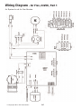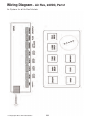
1
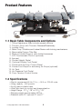
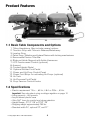
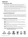
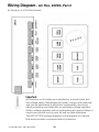
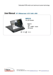
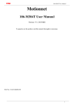
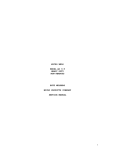
Hill Air-Flex Table
Owner’s Manual
Quality and Innovation Since 1945.
Congratulations!
And welcome to the Hill Laboratories family.
Hill Laboratories has been making quality a family business since 1945.
Your new Air-Flex is built on an established Hill tradition of innovation and
value. Our reputation rests on the confidence that your Hill Table will strengthen
this legacy by providing you with solid, reliable service for many years to come.
At Your Service
The Hill Laboratories Guarantee.
Your Hill Laboratories table has been thoroughly tested and
inspected before shipment. All parts are guaranteed against defect
in materials for one full year from the date of purchase. During this
period, any such defect will be remedied by Hill Laboratories or by
a factory-authorized repair service at no charge. Tables damaged
by mishandling or accident will be repaired at a reasonable charge.
All correspondence should be directed to your local dealer, or when
this is not possible, to Hill Laboratories directly.
For tables beyond the warranty period, our service technicians
are standing by to serve you. They can be reached toll-free at
1-877-445-5020 from 9 am - 5 pm E.S.T., Monday through Friday.
After hours, please leave your name, phone number and a brief
description of your concern. Your call will be returned promptly the
next business day.
We appreciate your business and your confidence in our products.
Our aim is to provide you with excellent service and satisfaction for
many years to come.
President, Hill Laboratories
Hill Air-Flex Manual
Table of Contents
Product Features
Basic Table Components _________________________________________________1.1
Specifications __________________________________________________________1.2
Table Care
Cleaning your Table______________________________________________________2.1
Caution and Symbol Explanation __________________________________________2.2
Basic Table Operation
Preparing the Air-Flex for your Patient ______________________________________3.1
Height Pedal ___________________________________________________________3.2
The Control Panel _______________________________________________________3.3
Manual Thoracic Release/Thoracic Air-Breakaway ____________________________3.4
Basic Distraction ________________________________________________________3.5
Basic Flexion (Balancing the Patient) _______________________________________3.6
Using the Rotation Lock
Using the Rotation Feature________________________________________________4.1
Returning the Rotation Feature to the Horizontal Position ______________________4.2
Using Air-Drops
Drop Selector Switches __________________________________________________5.1
Headpieces
Tilting Headpiece________________________________________________________6.1
Dual Drop Headpiece ____________________________________________________6.2
Raised Headpiece _______________________________________________________6.3
Cervical Flexion Headpiece _______________________________________________6.4
Translation/CBP Headpiece _______________________________________________6.5
Instructions for the Auto-Flexion Option
The Auto-Flexion Touchscreen ____________________________________________7.1
Switching to Auto-Flex ___________________________________________________7.2
Instructions for the Auto-Distraction Option
The Auto-Distraction Touchscreen _________________________________________8.1
Manual/Auto Mode ______________________________________________________8.2
Cervical Auto-Distraction _________________________________________________8.3
Trouble Shooting ____________________________________________Pages 16-17
Wiring Diagrams _____________________________________________Pages 18-20
Index of Terms _______________________________________________Pages 21-22
© Copyright 2011, Hill Laboratories
Product Features
5
4
3
2
1
6
15
7
8
13
11
9
10
12
1.1 Basic Table Components and Options
1. Tilting Headpiece. May include several options
2. Thoracic Drop with Thoracic Release/Breakaway
3. Lumbar Drop
4. Pelvic Drop / Rotation and Lateral Flexion with locking mechanisms
5. Removable Flexion Tiller Bar
6. Slide-out Ankle Support with Ankle Harnesses
7. LCD Touchscreen Control (optional)
8. Armrest
9. Corded Height Pedal
10. Optional Rocker Foot Pedal
11. Power and Air-Drop Control Panel
12. Power Foot Strips for activating Air-Drops (optional)
13. Air Tank
14. Air-Pressure Foot Pedal
15. Drop-Tension Control Knobs
1.2 Specifications
• Electric requirement 60 Hz, 115 v~, 4.8 A or 220-50 cycle
• Lifting capacity - 450 pounds
• Acrylic thermo-plastic base
• Ultra-Cell® foam for comfort and shape retention
• Height Range - 211/2”-28” or 221/2”-29”
• Shipping weight approximately 250 lbs.
• Standard width 24”, optional 22”, and 27”
© Copyright 2011, Hill Laboratories
2
14
Table Care
2.1 Cleaning your Table
Hill table upholstery may be cleaned with Hill Laboratories' Vinyl and Leather
Cleaner or any household dishwashing liquid mixed with water. Hill also
offers Protex™ Disinfectant Spray to protect against pathogens, including
MRSA, HIV, Staph and the H1N1 Swine Flu Virus. Many stubborn stains
can be removed by applying 91% rubbing alcohol (isopropyl alcohol) to the
stain and wiping with a dry, soft, lint-free cotton cloth, towel or soft bristle brush.
Caution: These solvents are highly flammable; do not use near open flame
or intense heat. Wear rubber gloves during all cleaning activities. When
cleaning other parts of your table (besides upholstery) use only nonabrasive household detergents and water.
Cleaning the LCD Touchscreen
To clean your LCD Screen, DO NOT use common glass cleaners. Apply a
light spray of distilled water or if necessary, a 50/50 mix of white vinegar and
distilled water. Use a very soft cloth (cotton or micro-fiber) and apply it to the
screen with gentle pressure. Do not press hard as this will damage the screen.
2.2 Caution and Symbol Explanation
Caution: Children should never be left alone in a room with the table but
should always be accompanied by an adult.
Caution: Always unplug the table before performing any maintenance.
Caution: Check table once a year to make sure all internal and external
bolts are secure.
Caution: The power cord should be located to avoid risk of tripping or
having objects rolled over or placed on top of it. Damaged cords should
be replaced with another of hospital grade.
Caution: Grounding reliability can only be achieved when connected to an
equivalent receptacle marked hospital only or hospital grade.
Symbols - Each of the symbols below are used in your table labeling.
An explanation of each is below.
Attention Symbol
consult accompanying
documents
Dangerous Voltage
Symbol
© Copyright 2011, Hill Laboratories
Type BF Applied
Part Symbol
3
Ground
Symbol
~
Alternating
Current
Symbol
Don’t Touch
Symbol
Basic Table Operation
3.1 Preparing the Air-Flex for your patient
Plug your table into any 110 volt
grounded outlet (or 220 volt - international).
photo 1
Paper Roll - Feed the paper through the
face cutout, around the paper bar (just
below the cutout) and over the headpiece
as shown. Close the paper cutter located on
the side of the headpiece (photo 1) and tear
off the excess.
Preparing the Air System
Press the green POWER button on the
Control Panel to use the table’s air-system. Each of the function buttons will light
consecutively and then turn off. The table’s
air-compressor may also turn on to replenish the air-supply. The compressor will stop
when the pressure reaches 90 lbs.* See 5.1,
“Using Air-Drops” for air-feature instructions.
photo 2
*If the air-compressor runs for more than 2-3
minutes, call for service (see page 17).
Note: The Air-Flex is equipped with an
Auto Shutdown mode which will power
down the main control board if the table
is inactive for 2 hours. Press the green
power button to power the board back up.
photo 3
photo 4
Unlock
Note: It is very important that all three
locking handles are firmly locked, pointLock
ing towards the floor before positioning
your patient on the table (photo 3). This
will prevent unwanted movement and
potential injury to the patient. If your
table has a Thoracic Breakaway, be sure it is also locked before positioning
your patient (photo 4).
3.2 Height Pedal
The basic Air-Flex is equipped with a corded foot pedal (#9 under “Product
Features”) which controls the table height. Press the right side of the pedal
to elevate; the left side to lower. For tables equipped with a rocker foot pedal
(#10, page 2), height may be adjusted from either side of the table.
© Copyright 2011, Hill Laboratories
4
Auto-Touch Foot Pedal (option)
The Auto-Touch Foot Pedal option maintains upward or downward motion even
after releasing the pedal. To operate:
- When the table is at minimum height, double-touch the “UP” arrow and release.
The table will continue upward until you tap either side of the pedal again.
- When the table is at maximum height, double-touch the “DOWN” arrow and release. The table will continue downward until you tap either side of the pedal again.
- When the table is at any starting height in between, a single-touch up or down
will start and stop the motion.
3.3 The Control Panel
The Air-Flex control panel (photo 5) has a power button, drop-selector buttons,
and a breakaway, flexion and distraction button. After power, press in any order
to activate the corresponding function. The Flexion, Distraction and Breakaway
functions can be used in any order but must be used independently of one another. See section 5.1”Using Air-Drops” for further instruction.
3.4 Manual Thoracic Release/Thoracic Air-Breakaway
Thoracic Release
To operate the Thoracic Release, pull the lever towards you
while holding the cushion; adjust to the desired
depth. Release the lever to lock the cushion.
Thoracic Air-Breakaway
For tables with a Thoracic Air-Breakaway, it is necessary to regulate the airpressure before treating your patient. Follow these steps:
1. Select the ‘BRKY’ (breakaway) button on the main control panel (photo 5).
2. Unlock the thoracic breakaway switch by pulling toward you until it clicks
(photo 4). This will allow the cushion to move freely up and down.
3. Press the right side of the Pressure Pedal (#13, page 2) to increase the
air-pressure or left side to decrease
in the thoracic section. Push down
on the cushion as you add air to test
for desired firmness.
4. Lock the cushion at any point by
pushing the thoracic lock switch towards the table until it clicks.
© Copyright 2011, Hill Laboratories
5
photo 5
3.5 Basic Distraction
The following explains how to use the
basic distraction feature on the Air-Flex.
For detailed instruction on Auto-Distraction, see page 12.
photo 6
1. Remove the Tiller Bar from its bracket
between the ankle and pelvic cushion. (see page 2, #5).
2. Place the patient face down on the
table with feet extended over the
ankle rest.
3. Pull and hold the Slide-Out Ankle
Support lock (photo 6) to extent the
table length to fit the patient’s height.
photo 7
4. Secure the Ankle Straps around the patient’s ankles.
5. Select the ‘DIST’ (distraction) button on the control panel.
6. Using the Pressure Pedal, increase the air-pressure to distract the patient.
Note: The speed rate of distraction can be adjusted by opening or closing
the air-regulator under the thoracic cushion (photo 7).
3.6 Basic Flexion (Balancing the Patient)
This section explains how to balance your
patient and how to use basic flexion on
the Air-Flex. For detailed instruction on
the Auto-Flexion Feature, see page 10.
1. Be sure that the Flexion Lock is in the
6 o’clock, locked position (photo 8).
Insert the Tiller Bar back into its bracket.
photo 8
2. Select the ‘FLEX’ (flexion) button on
Control Panel.
3. “Pre-pressure” the pelvic cushion to
support the patient by pressing the
pressure pedal. Ex: For a patient
weighing 150-200 lbs., add pressure until the control panel gauge
reads 40 – 50 lbs.
B
A
photo 9
4. While holding the end of the table, disengage the Flexion Lock by turning
the handle counter-clockwise—to the 4 o’clock position (A, photo 9).
Now the patient is completely supported by air-pressure. Depending on
the patient’s weight, you may need to adjust the air-pressure to counterbalance the patient until only a small amount of force is required to flex
© Copyright 2011, Hill Laboratories
6
the patient. If the table does not spring back automatically to a horizontal,
resting position, slightly increase the pressure.
5. For lateral movement, unlock the Lateral Locking Handle to the 4 o’clock
position (B, photo 9).
Note: The table can be locked in any position along the flexion and/or lateral
axis by turning the handle to the 6 o’clock position.
Using the Rotation Lock
The Rotation feature of the Air-Flex can be unlocked for free movement or
locked at any angle. Unlike the flexion and lateral locks, the rotation lock is
lever-controlled. A centering handle (A, photo 10) is also provided to locate
and lock the pelvic cushion in the horiA
photo 10
zontal position.
B
4.1 Using the Rotation Feature
Turn the centering handle to the 4 o’clock
position (A, photo 10). Unlock the rotation
lever by pulling out until it clicks (B, photo
10) This will allow free movement in rotation.
To lock the rotation at any angle, simply
push the rotation lever in towards the patient (B, photo 10).
4.2 Returning the Rotation Feature to the Horizontal Position
1. Unlock lever (B, photo 11)
2. Manually move the pelvic section to a
horizontal position.
3. Engage the centering handle by turning it to the 6 o’clock position (A, 11).
photo 11
A
Note: If the centering handle will not
lock, the pelvic cushion is not yet horizontal. Adjust the cushion until the
handle locks.
4. Lock the rotation lever (B photo 11) by
pushing it in, towards the table.
Important! The centering handle alone is
not sufficient to secure the rotation function. Be sure to also lock the rotation lever to properly secure rotation.
© Copyright 2011, Hill Laboratories
7
B
Using Air-Drops
5.1 Drop Selector Switches
The Drop Selector Switches (photo 12)
activate the table drops. You may select
one or up to four drops simultaneously.
Once selected, pressing the Pressure
pedal (or optional foot strips) activates
photo 12
the drops. Once drops are discharged,
pressing the pedal or foot strip again immediately reactivates them.
Drop-Tension Control Knobs
The Drop-Tension Knobs are located on the left side of each drop (#15,
page 2). Turn the knob clockwise to increase the firmness of the drop—
counter clockwise to decrease.
Caution: Do not loosen Tension Knobs too far Adjusting the tension knobs out too
far can cause the cervical (and pelvic) drops to malfunction. See The “Trouble
Shooting” section on page 16 for more detail.
Headpieces
6.1 Tilting Headpiece
All Air-Flex models are equipped with a tilting headpiece. The lever for tilting is
located under the front of the headpiece (A, photo 13). It controls the angle of tilt
30° positive or negative. Pull the lever to unlock; adjust the angle; release to lock.
6.2 Dual-Drop Headpiece
The Dual-Drop headpiece contains two drops—a drop-forward motion and a
straight-down drop.
Important Note: Before changing any of
the settings described in the following
section, be sure the headpiece drop is
discharged.
photo 13
C
A
B
Drop-Forward Motion Headpiece
To use the Drop-Forward Motion of the
headpiece, the setting lever should remain in the side channel of the setting
mechanism as shown in photo 14. Be sure that the pin locks into the receiver
behind it—otherwise, the drop will not work. For a manual drop, push up on
the black cocking handle to engage. For Air-Cervical Drop, see section 5.1.
© Copyright 2011, Hill Laboratories
8
Straight-Down Drop Headpiece
To use the Straight-Down Drop action of
the headpiece, pull the black setting
lever out and turn it to the left so that it
points straight down (photo 15). For a
manual drop, push up on the black
cocking handle to engage.
For Air-Cervical Drop, see section 5.1).
photo 14
photo 15
6.3 Raised Headpiece
The Raised Headpiece allows the headpiece to rise up to 5” above the surface of
the table. It is controlled by a lever in front
of the head cushion (B, photo 13). Pull and
hold the switch to adjust to the desired
height; release to lock. To lower, apply gentle downward pressure to the thoracic
end of the headpiece with one hand while pulling the lever to adjust.
6.4 Cervical Flexion/Distraction
photo 16
The Cervical Flexion Headpiece includes
the raised headpiece feature, occipital
strap and the removable tiller bar.
Note: Cervical Flexion, Distraction and
Lateral Motion (described below) can be
used separately or in combination.
Cervical Flexion
photo 17
Position the patient as shown in photo 16.
Secure the occipital strap using the
Velcro® connectors. Use the Tiller Bar
to apply flexion.
Cervical Distraction
Important: To use Manual Cervical Distraction you must first unlock the cushion for long axis motion by releasing
the red lock pin (shown in photo 17).
Pull and turn the lever to the left.
Cervical Lateral Motion
The Cervical Flexion Headpiece includes
lateral motion. To use lateral motion, locate
the switch as shown in photo 18 (or C,
photo 13). Pull the lever toward you to click
© Copyright 2011, Hill Laboratories
9
photo 18
and unlock. This will allow full-range lateral
movement. The headpiece can also be
locked at any angle in the lateral range.
6.5 Translation/CBP Headpiece
To use the translation headpiece, loosen
the black knob in front of the headpiece
by turning it counterclockwise. Push the
cushion left or right to the desired position;
turn clockwise to tighten the knob.
photo 13
Instructions for the Auto-Flexion Option
Safety Caution: The moveable parts of the Auto-Flex feature can cause severe
injury if handled improperly. Children should always be accompanied by an
adult when in the room with the Air-Flex table.
7.1 The Auto-Flexion Touchscreen
The Auto-Flexion and Auto-Distraction features are both controlled by the
touchscreen located on the pelvic section (See #7 under “Basic Table Functions”). You may easily toggle back and forth between the Auto-Flexion and
Auto-Distraction display by pressing the “Dist/Flex” button respectively.
Auto-Flexion Touchscreen: Functions Defined
DEPTH - Defines the depth of the flexion stroke from 1-10
SPEED - Defines the speed of the flexion stroke from 1-12
HOLD - Defines the number of seconds
the table “holds” at the set depth during each flexion cycle.
REST - Defines the number of seconds
the table “rests” horizontally during
each flexion cycle.
CYCLES - Defines the number of desired
flexion cycles for treatment.
Press the Dist/Flex button to
toggle between Flexion and
Distraction screens.
RUN - Starts treatment.
PAUSE - Pauses treatment (photo 19)
SLIDER - Sets the amount for any selected function.
DIST/FLEX - Toggles between flexion and
distraction screens.
© Copyright 2011, Hill Laboratories
10
photo 19
PAUSE
7.2 Switching to Auto-Flex
Important: Before proceeding with Auto-Flexion, read Section 3.6 on ‘Basic
Flexion (Balancing the Patient)’.
It is very important that you become familiar with how to balance your patient
BEFORE USING the Auto-Flex feature. THE PATIENT MUST BE SUPERVISED AT ALL
TIMES DURING OPERATION.
1. Balance your patient by following steps 1 - 4 under section 3.6 “Basic
Flexion”. Patient should start in a slightly flexed position.
2. To begin using the Auto-Flexion Touch
Screen, press the “FLEX” button
(Photo 21) on the main control panel.
The touch screen should already be
lit. By default, the touchscreen displays
the settings from the last treatment.
At start up, the touchscreen displays
the Auto-Distraction screen (if so
equipped). Press the “Dist/Flex” button
to switch to the Auto-Flexion display.
photo 21
3. Set each of your touchscreen settings
by touching each button in turn
(buttons will turn blue when selected)
and adjusting the slider for the desired setting.
Note: Adjusting the slider works best
with the back of your finger or by simply tapping the slide bar at the desired point on the slide bar.
photo 22
4. With settings selected, press “RUN” to start the treatment and move the
flexion locking handle to the 1 o’clock position to engage the motor (Photo
22 - see note below). You will feel the handle move a cam into a lock position.
Note: Once the RUN Button is pressed, the operator has 30 seconds to engage the
Auto-Flex motor by turning the flexion lock handle to the 1 o’clock position (photo 22).
If not engaged within that time, the motor will shut off.
6. Press the yellow “PAUSE” button at any time to pause the treatment or to
adjust your settings. Press PAUSE again to restart the treatment.
7. When the cycle time ends, the table will return to the rest/horizontal
position. Before the patient exits the table, be sure the flexion, rotation
and lateral lock handles are all turned to the 6 o’clock/locked position.
Note: When using distraction with Auto-Flex, flexion may not need to be as
deep. Making a note of your settings for each patient makes it easy to duplicate treatment on subsequent visits.
© Copyright 2011, Hill Laboratories
11
Emergency Stopping for Auto-Distraction
To immediately stop an Auto-Distraction treatment at any time, press the
STOP button on the
Patient
touchscreen (right). The
patient can also stop
Switch
the treatment with the
Stop-Treatment Patient
Switch, shown right.
Instructions for the Auto-Distraction Option
To use distraction on the Air-Flex, first
press the “DIST” button on the main control panel (photo 23). If this is the first
treatment after table start-up, the touchscreen will automatically display the
Auto-Distraction display. If you have already been using the touchscreen for
Auto-Flexion, simply press the “Dist/Flex”
button to enter Auto-Distraction.
photo 23
NOTE: The Air-Flex can be locked in any flexion or lateral position during
Auto-Distraction.
8.1 The Auto-Distraction Touchscreen
Auto-Distraction functions defined:
REST - Describes the duration of the
treatment Rest Cycle in seconds. lt is
programmable from 5 to 60 seconds.
During a treatment, the Rest Cycle will
highlight and countdown the seconds
remaining in that cycle.
PULL - Describes the duration of the treatment Pull Cycle in seconds. lt is
programmable from 5 seconds to 60 seconds. During a treatment, the Pull
Cycle will highlight and countdown the seconds remaining in that cycle.
REST% - Rest % is used to calculate the Force during the Rest Cycle. lt can
be set to either 25% or 50%. For example, with a Force Setting of 40 lbs
during the Pull Cycle, setting the Rest % to 25% will administer 10 lbs of
Force during the Rest Cycle. A 50% setting yields 20 lbs. during Rest Cycle.
TIME - Describes the duration of the treatment time in minutes. The display
will count down once the treatment has begun.
FORCE - The treatment Force is measured in U.S. pounds. It is programmable
from 5 lbs-100 lbs for a Lumbar Treatment and 2 lbs– 50 lbs for a Cervical
© Copyright 2011, Hill Laboratories
12
Treatment. During a treatment, the Force Setting will show the measured
force in real-time.
ARROWS - The Up and Down Arrow Buttons are used to increase and decrease the treatment setting values. To edit a value, simply touch it and it
will highlight in BLUE. Then use the arrow keys to enter the desired value.
LUMBAR/CERVICAL - The CERV/LMBR button indicates which distraction
treatment type the table is currently set for.
If your table is equipped for both lumbar
and cervical distraction, pressing the
CERV/LMBR button will toggle between the
two functions respectively. If your Air-Flex
is only equipped with one auto-distraction
option, you will not need to use this button.
MAN/AUTO - Manual/Automatic Button indicates which type of distraction mode
(see below) you want to use. Press the button to toggle back and forth between MAN and AUTO.
RUN: Pressing RUN starts the treatment. While the system is in run mode
the status display will flash "Run Mode Active" (see below).
8.2 Manual/Auto Mode
Manual Mode (MAN)
Manual Mode allows you to manually distract your patient using the pressure
foot pedal. The Force Setting shows the pounds being administered to
your patient once you release the foot pedal. This force will now be used
as the peak force once the RUN button is pressed.
NOTE: For safety, Manual mode is not available while in Cervical Distraction.
Automatic Mode (AUTO)
Automatic Mode allows the table to automatically distract your patient with
the amount of force you have set. The lumbar default setting is 50 lbs.; the
cervical default setting is 10 lbs. Settings can also be changed before or
during treatment using the up and down arrows.
Run Mode
Once the RUN button is pressed, the treatment
begins and the status display flashes “Run Mode
Active”. While in Run Mode, the system cycles from
Pull to Rest while displaying the actual Force being
distributed in real-time in the FORCE display.
© Copyright 2011, Hill Laboratories
13
Stop Treatment
If the patient presses the hand-held patient cut-off
switch (also see “Emergency Stopping, page 12),
the treatment will end immediately and the status
screen will display "Patient Cancelled Treatment".
The system will vent and needs to be reset (see below).
lf during a treatment the stop button is pressed
(page 12), the treatment will end immediately and the
status screen will display "Treatment Cancelled by
Stopping". The system will vent and needs to be
reset.
Following a successful treatment the timer resets and
the status screen will read "Treatment Time Finished".
The system will vent and needs to be reset.
Reset Button
The reset button appears below the status
display (see right). The reset button resets
the air-system for another treatment and
saves the current settings. It is necessary
to press the reset button at the end of each
treatment.
8.3 Cervical Auto-Distraction
Using Cervical Distraction
Insert the Cradle - First insert the cradle
assembly into the receptacle at the
end of the headpiece (A, photo 24).
Position the Patient - Gently insert the
patient’s neck into the cradle support
with the insert pad facing the ceiling.
Tighten the tension knob until the patient feels a slight inward pressure (A,
photo 25). Secure the forehead straps
with the Velcro connectors and tilt the
headpiece about 5-10° (photo 24).
Grasp the patient’s ankles and gently
pull towards the foot end of the table to
ensure that the patient’s occipital region rests upon the upper inside ridge
of the cradle support (photo 25).
© Copyright 2011, Hill Laboratories
14
photo 24
A
B
A
photo 25
Unlock the Headpiece (Very Important!) - Pull and rotate the red pin located underneath the headpiece cushion by pulling the red handle out and left . This
will unlock the headpiece for Auto-Distraction (see photo 17).
Enter Settings - Touch the cervical (CERV) button on the touchscreen and
enter your treatment settings. Follow the same procedure used for Lumbar
Distraction (See Section 8.1, “The Auto-Distraction Touchscreen”). Push the
green run button to start the treatment.
Emergency Stop - Like Lumbar Distraction, Emergency Stop can be used at
any time by you or your patient. See “Emergency Stopping for Auto-Distraction” under section 7.2.
Important Notes for Cervical Distraction
For Safety - No Foot-Pedal Control
Cervical Auto-Distraction is controlled by the touchscreen in the same way as
Lumbar Auto-Distraction. Unlike Lumbar Distraction, Cervical Distraction cannot be controlled ‘manually’ with the foot pedal.
Screen Saver
When the touchscreen is not in use for several minutes, a screen saver will appear. Touching the screen will return to settings.
© Copyright 2011, Hill Laboratories
15
Maintenance
Regular Maintenance
Your Hill AFT is practically maintenance free. There is no lubrication of
parts needed.
Trouble Shooting
C
B
Problem
The Pelvic Cushion cocks but does not stay up.
The drop pin has come out of it’s track.
To Fix:
1. Loosen the Pelvic Drop Tension Knob
enough to rotate the drop pin (see “A” in
drawing) so that the cross pin (B) faces
and engages the bracket
(C) as shown in the photo
and drawing below. You
may need to use a flat head
screw driver to turn the pin
from the bottom. Once the
pin is turned into the
bracket, retighten the Tension Knob.
A
C
A
B
Problem
The Cervical Cushion cocks up but does not stay up.
The drop pin has come out of it’s L-bracket.
To Fix:
1. Loosen the Cervical Drop Tension
Knob enough to rotate the drop pin
(see “A” in photo) so that the spring
pin (B) faces and engages the
bracket (C) as shown in the photo .
Once the pin is turned into the
bracket, retighten the Tension Knob.
C
B
A
© Copyright 2011, Hill Laboratories
16
Problem
The main power board is turning off on it’s
own. This is likely the Auto-Shutdown mode
operating normally.
When the Air-Flex is left inactive for 2
hours, the Auto-Shutdown mode will
power the main control board down
automatically.
To Fix:
Simply press the green power button.
Problem
The pelvic cushion bounces up and down when the Auto-Flex motor is engaged.
To Fix:
Increase the air-pressure by pressing the pressure foot pedal.
Additional service needed?
Contact your local dealer or reach us directly:
Phone: 1-877-445-5020
Fax: 610-647-6297
Email: [email protected]
Technicians are available 9 am - 4 pm E.S.T., Monday - Friday.
© Copyright 2011, Hill Laboratories
17
Wiring Diagram - Air Flex, 24VDC, Part 1
Air System for all Air-Flex Models.
© Copyright 2011, Hill Laboratories
18
Wiring Diagram - Air Flex, 24VDC, Part 2
Air System for all Air-Flex Models.
© Copyright 2011, Hill Laboratories
19
Wiring Diagram - Air Flex, 24VDC, Part 3
Height System for all Air-Flex Models.
© Copyright 2011, Hill Laboratories
20
Index
A
Air-Compressor 4
E
Electrical specifications 2
Emergency Stop
- Patient Switch 12, 14
- Stop Button 12, 14
Ankle Support
- Adjusting 2, 6
- Straps 2, 6
Armrests 2
F
Flexion
- Auto 10-12
- Basic/Manual 6
- Cervical 9
Auto-Distraction 12-15
Auto-Flexion 10-12
Automatic Mode (also see “Run Mode”) 13
Auto Shutdown 4,17
Foot Pedal
- Auto-Touch 5
- Corded 2, 4
- Rocker 2, 4
Auto-Touch Foot Pedal 5
B
Balancing the Patient 6
Foot Strips 2, 8
Basic Table Components 2
H
Headpiece 2, 4, 8
- Air-Drop 8
- CBP/Translation 10
- Dual-Drop 8
- Flexion 9
- Lateral Adjustment 9
- Raised 9
- Tilting 8
- Translation/CBP 10
C
Cervical Distraction 14, 15
Cervical Flexion (see “Flexion”) 9
Cleaning your table 3
Cautions and Symbols 3
Control Panel 4, 5, 6, 11, 12
D
Distraction
- Auto 12-14
- Basic 6
- Cervical 14, 15
Height Range 2
Height Pedal 4
K
Knobs (See Tension Control Knobs)
Drops
- Cervical
- Operating 8, 9
- Not popping up 16
- Lumbar
- Operating 8
- Pelvic
- Operating 8
- Not popping up 16
- Thoracic
- Operating 8
© Copyright 2011, Hill Laboratories
L
Lateral Adjustment
- Cervical 9
- Pelvic 7
LCD (see “Touchscreen”)
Lifting Capacity 2
Locking Mechanisms
- Flexion 4, 6
- Headpiece 8-10
- Lateral 7, 9
21
Index
Tiller Bar 2, 6, 9
L (continued)
- Rotation 2, 7
- Thoracic Breakaway 4, 5
- Thoracic Release 4, 5
Timer 14
Thoracic Breakaway 4, 5
Thoracic Drop (see “Drops”)
M
Maintenance 16
Manual Flexion (See Flexion)
Thoracic Release 4, 5
Touchscreen
- Cleaning 3
- Functions and Operation 10-14
N
Not Working (See Auto Shutdown)
Trouble Shooting 16, 17
W
Warranty See intro, “At Your Service”
O
On/Off Switch (See Power Button)
Wiring diagrams 18 - 20
P
Paper Roll 4
Patient Switch (see “Emergency Stop”)
Pause Treatment 10, 11
Power Button 4, 5, 17
R
Raised Headpiece (See Headpieces)
Reset Button 14
Rocker Foot Pedal (See Foot Pedal)
Rotation
- Locking 7
- Operating 7
- Treating without 7
Run Mode (Also see “Automatic Mode”) 13
S
Service and Support See intro, “At Your Service”
Specifications 2
Speed Setting 10
Stop Button (Also see “Emergency Stop”)
T
Table Components 4
Tension Control Knobs 2, 8
© Copyright 2011, Hill Laboratories
22
3 N. Bacton Hill Road, Frazer, PA 19355 • www.HillLabs.com
610-644-2867 • 1-877-445-5020 • Fax 610-647-6297
Congratulations!
And welcome to the Hill Laboratories family.
Hill Laboratories has been making quality a family business since 1945.
Your new Air-Flex is built on an established Hill tradition of innovation and
value. Our reputation rests on the confidence that your Hill Table will strengthen
this legacy by providing you with solid, reliable service for many years to come.
At Your Service
The Hill Laboratories Guarantee.
Your Hill Laboratories table has been thoroughly tested and
inspected before shipment. All parts are guaranteed against defect
in materials for one full year from the date of purchase. During this
period, any such defect will be remedied by Hill Laboratories or by
a factory-authorized repair service at no charge. Tables damaged by
mishandling or accident will be repaired at a reasonable charge. All
correspondence should be directed to your local dealer, or when
this is not possible, to Hill Laboratories directly.
For tables beyond the warranty period, our service technicians
are standing by to serve you. They can be reached toll-free at
1-877-445-5020 from 9 am - 5 pm E.S.T., Monday through Friday.
After hours, please leave your name, phone number and a brief
description of your concern. Your call will be returned promptly the
next business day.
We appreciate your business and your confidence in our products.
Our aim is to provide you with excellent service and satisfaction for
many years to come.
President, Hill Laboratories
Hill Air-Flex Manual
Table of Contents
Product Features
Basic Table Components _________________________________________________1.1
Specifications __________________________________________________________1.2
Table Care
Cleaning your Table______________________________________________________2.1
Caution and Symbol Explanation __________________________________________2.2
Basic Table Operation
Preparing the Air-Flex for your Patient_______________________________________3.1
Height Pedal ___________________________________________________________3.2
The Control Panel _______________________________________________________3.3
Manual Thoracic Release/Thoracic Air-Breakaway ____________________________3.4
Basic Distraction ________________________________________________________3.5
Basic Flexion (Balancing the Patient) _______________________________________3.6
Using the Rotation Lock
Using the Rotation Feature________________________________________________4.1
Returning the Rotation Feature to the Horizontal Position ______________________4.2
Using Air-Drops
Drop Selector Switches __________________________________________________5.1
Headpieces
Tilting Headpiece________________________________________________________6.1
Dual Drop Headpiece ____________________________________________________6.2
Raised Headpiece_______________________________________________________6.3
Cervical Flexion Headpiece _______________________________________________6.4
Translation/CBP Headpiece _______________________________________________6.5
Instructions for the Auto-Flexion Option
The Auto-Flexion Touchscreen_____________________________________________7.1
Switching to Auto-Flex ___________________________________________________7.2
Instructions for the Auto-Distraction Option
The Auto-Distraction Touchscreen__________________________________________8.1
Manual/Auto Mode ______________________________________________________8.2
Cervical Auto-Distraction _________________________________________________8.3
Trouble Shooting _____________________________________________Pages 16-17
Wiring Diagrams _____________________________________________Pages 18-20
Index of Terms _______________________________________________Pages 21-22
© Copyright 2011, Hill Laboratories
Product Features
5
4
3
2
1
6
15
7
8
13
11
9
10
12
1.1 Basic Table Components and Options
1. Tilting Headpiece. May include several options
2. Thoracic Drop with Thoracic Release/Breakaway
3. Lumbar Drop
4. Pelvic Drop / Rotation and Lateral Flexion with locking mechanisms
5. Removable Flexion Tiller Bar
6. Slide-out Ankle Support with Ankle Harnesses
7. LCD Touchscreen Control (optional)
8. Armrest
9. Corded Height Pedal
10. Optional Rocker Foot Pedal
11. Power and Air-Drop Control Panel
12. Power Foot Strips for activating Air-Drops (optional)
13. Air Tank
14. Air-Pressure Foot Pedal
15. Drop-Tension Control Knobs
1.2 Specifications
• Electric requirement 115 v~, 60 Hz, 4.8 A or 230v~, 50 Hz
Important: See note about using a voltage regulator on page 19
• Lifting capacity - 450 pounds
• Acrylic thermo-plastic base
• Ultra-Cell® foam for comfort and shape retention
• Height Range - 211/2”-28” or 221/2”-29”
• Shipping weight approximately 250 lbs.
• Standard width 24”, optional 22”, and 27”
© Copyright 2011, Hill Laboratories
2
14
Table Care
2.1 Cleaning your Table
Hill table upholstery may be cleaned with Hill Laboratories' Vinyl and
Leather Cleaner or any household dishwashing liquid mixed with water. Hill
also offers Protex™ Disinfectant Spray and wipes to protect against
pathogens, such as MRSA, HIV, Staph and the H1N1 Swine Flu Virus. Many
stubborn stains can be removed by applying 91% rubbing alcohol (isopropyl
alcohol) to the stain and wiping with a dry, soft, lint-free cotton cloth, towel or
soft bristle brush. Be sure to rinse thoroughly with water.
Caution: Some solvents are highly flammable; do not use near open flame
or intense heat. Wear rubber gloves during all cleaning activities. When
cleaning other parts of your table (besides upholstery) use only nonabrasive household detergents and water.
Cleaning the LCD Touchscreen
To clean your LCD Screen, DO NOT use common glass cleaners. Apply a
light spray of distilled water or if necessary, a 50/50 mix of white vinegar and
distilled water. Use a very soft cloth (cotton or micro-fiber) and apply it to the
screen with gentle pressure. Do not press hard as this will damage the screen.
2.2 Caution and Symbol Explanation
Caution: Children should never be left alone in a room with the table but
should always be accompanied by an adult.
Caution: Always unplug the table before performing any maintenance.
Caution: Check table once a year to make sure all internal and external
bolts are secure.
Caution: The power cord should be located to avoid risk of tripping or
having objects rolled over or placed on top of it. Damaged cords should
be replaced with another of hospital grade.
~
Caution: Grounding reliability can only be achieved when connected to an
equivalent receptacle marked hospital only or hospital grade.
Symbols - Each of the symbols below are used in your table labeling.
An explanation of each is below.
Attention Symbol
consult accompanying
documents
Dangerous Voltage
Symbol
© Copyright 2011, Hill Laboratories
Type BF Applied
Part Symbol
3
Ground
Symbol
Alternating
Current
Symbol
Don’t Touch
Symbol
Basic Table Operation
3.1 Preparing the Air-Flex for your patient
Plug your table into any 110 volt grounded
outlet (or 220 volt - international).
Paper Roll - Feed the paper through the
face cutout, around the paper bar (just
below the cutout) and over the headpiece
as shown. Close the paper cutter located on
the side of the headpiece (photo 1) and tear
off the excess.
photo 1
Preparing the Air System
Press the green POWER button on the
Control Panel to use the table’s air-system. Each of the function buttons will light
consecutively and then turn off. The table’s
air-compressor may also turn on to replenish the air-supply. The compressor will stop
when the pressure reaches 90 lbs.* See
5.1, “Using Air-Drops” for air-feature instructions.
*If the air-compressor runs for more than 2-3
minutes, call for service (see page 17).
Note: The Air-Flex is equipped with an
Auto Shutdown mode which will power
down the main control board if the table
is inactive for 2 hours. Press the green
power button to power the board back up.
photo 2
photo 3
photo 4
Note: It is very important that all three
locking handles are firmly locked, pointing towards the floor before positioning
your patient on the table (photo 3). This
will prevent unwanted movement and
potential injury to the patient. If your table has a Thoracic Breakaway, be
sure it is also locked before positioning your patient (photo 4).
3.2 Height Pedal
The basic Air-Flex is equipped with a corded foot pedal (#9 under “Product
Features”) which controls the table height. Press the right side of the pedal
to elevate; the left side to lower. For tables equipped with a rocker foot pedal
(#10, page 2), height may be adjusted from either side of the table.
© Copyright 2011, Hill Laboratories
4
Auto-Touch Foot Pedal (option)
The Auto-Touch Foot Pedal option maintains upward or downward motion even
after releasing the pedal. To operate:
- When the table is at minimum height, double-touch the “UP” arrow and release.
The table will continue upward until you tap either side of the pedal again.
- When the table is at maximum height, double-touch the “DOWN” arrow and release. The table will continue downward until you tap either side of the pedal again.
- When the table is at any starting height in between, a single-touch up or down
will start and stop the motion.
3.3 The Control Panel
The Air-Flex control panel (photo 5) has a power button, drop-selector buttons,
and a breakaway, flexion and distraction button. After power, press in any order
to activate the corresponding function. The Flexion, Distraction and Breakaway
functions can be used in any order but must be used independently of one another. See section 5.1”Using Air-Drops” for further instruction.
3.4 Manual Thoracic Release/Thoracic Air-Breakaway
Thoracic Release
To operate the Thoracic Release, pull the lever towards you
while holding the cushion; adjust to the desired
depth. Release the lever to lock the cushion.
Thoracic Air-Breakaway
For tables with a Thoracic Air-Breakaway, it is necessary to regulate the airpressure before treating your patient. Follow these steps:
1. Select the ‘BRKY’ (breakaway) button on the main control panel (photo 5).
2. Unlock the thoracic breakaway switch by pulling toward you until it clicks
(photo 4). This will allow the cushion to move freely up and down.
3. Press the right side of the Pressure Pedal (#13, page 2) to increase the
air-pressure or left side to decrease
in the thoracic section. Push down
on the cushion as you add air to test
for desired firmness.
4. Lock the cushion at any point by
pushing the thoracic lock switch towards the table until it clicks.
© Copyright 2011, Hill Laboratories
5
photo 5
3.5 Basic Distraction
The following explains how to use the
basic distraction feature on the Air-Flex.
For detailed instruction on Auto-Distraction, see page 12.
photo 6
1. Remove the Tiller Bar from its bracket
between the ankle and pelvic cushion.
(see page 2, #5).
2. Place the patient face down on the
table with feet extended over the ankle
rest.
3. Pull and hold the Slide-Out Ankle Support lock (photo 6) to extent the table
length to fit the patient’s height.
photo 7
4. Secure the Ankle Straps around the patient’s ankles.
5. Select the ‘DIST’ (distraction) button on the control panel.
6. Using the Pressure Pedal, increase the air-pressure to distract the patient.
Note: The speed rate of distraction can be adjusted by opening or closing the
air-regulator under the thoracic cushion (photo 7).
3.6 Basic Flexion (Balancing the Patient)
This section explains how to balance your
patient and how to use basic flexion on
the Air-Flex. For detailed instruction on the
Auto-Flexion Feature, see page 10.
1. Be sure that the Flexion Lock is in the
6 o’clock, locked position (photo 8).
Insert the Tiller Bar back into its
bracket.
2. Select the ‘FLEX’ (flexion) button on
Control Panel.
photo 8
3. “Pre-pressure” the pelvic cushion to
B
support the patient by pressing the
pressure pedal. Ex: For a patient
photo 9
weighing 150-200 lbs., add pressure
until the control panel gauge reads 40 – 50 lbs.
A
4. While holding the end of the table, disengage the Flexion Lock by turning the
handle counter-clockwise—to the 4 o’clock position (A, photo 9). Now the
patient is completely supported by air-pressure. Depending on the patient’s
weight, you may need to adjust the air-pressure to counterbalance the
patient until only a small amount of force is required to flex the patient. If the
© Copyright 2011, Hill Laboratories
6
table does not spring back automatically to a horizontal, resting position,
slightly increase the pressure.
5. For lateral movement, unlock the Lateral Locking Handle to the 4 o’clock position (B, photo 9).
Note: The table can be locked in any position along the flexion and/or lateral
axis by turning the handle to the 6 o’clock position.
Using the Rotation Lock
The Rotation feature of the Air-Flex can be unlocked for free movement or
locked at any angle. Unlike the flexion and lateral locks, the rotation lock is
lever-controlled. A centering handle (A, photo 10) is also provided to locate and
lock the pelvic cushion in the horizontal
photo 10
position.
A
B
4.1 Using the Rotation Feature
Turn the centering handle to the 4 o’clock
position (A, photo 10). Unlock the rotation
lever by pulling out until it clicks (B, photo
10) This will allow free movement in rotation.
To lock the rotation at any angle, simply
push the rotation lever in towards the patient (B, photo 10).
4.2 Returning the Rotation Feature to the Horizontal Position
1. Unlock lever (B, photo 11)
2. Manually move the pelvic section to a
horizontal position.
3. Engage the centering handle by turning
it to the 6 o’clock position (A, 11).
photo 11
A
Note: If the centering handle will not
lock, the pelvic cushion is not yet horizontal. Adjust the cushion until the handle locks.
4. Lock the rotation lever (B photo 11) by
pushing it in, towards the table.
Important! The centering handle alone is
not sufficient to secure the rotation function. Be sure to also lock the rotation lever to properly secure rotation.
© Copyright 2011, Hill Laboratories
7
B
Using Air-Drops
5.1 Drop Selector Switches
The Drop Selector Switches (photo 12)
activate the table drops. You may select
one or up to four drops simultaneously.
Once selected, pressing the Pressure
pedal (or optional foot strips) activates
photo 12
the drops. Once drops are discharged,
pressing the pedal or foot strip again immediately reactivates them.
Drop-Tension Control Knobs
The Drop-Tension Knobs are located on the left side of each drop (#15,
page 2). Turn the knob clockwise to increase the firmness of the drop—
counter clockwise to decrease.
Caution: Do not loosen Tension Knobs too far Adjusting the tension knobs out too
far can cause the cervical (and pelvic) drops to malfunction. See The “Trouble
Shooting” section on page 16 for more detail.
Headpieces
6.1 Tilting Headpiece
All Air-Flex models are equipped with a tilting headpiece. The lever for tilting is
located under the front of the headpiece (A, photo 13). It controls the angle of tilt
30° positive or negative. Pull the lever to unlock; adjust the angle; release to lock.
6.2 Dual-Drop Headpiece
The Dual-Drop headpiece contains two drops—a drop-forward motion and a
straight-down drop.
Important Note: Before changing any of
the settings described in the following
section, be sure the headpiece drop is
discharged.
Drop-Forward Motion Headpiece
photo 13
C
A
B
To use the Drop-Forward Motion of the headpiece, the setting lever should
remain in the side channel of the setting mechanism as shown in photo 14.
Be sure that the pin locks into the receiver behind it—otherwise, the drop will
not work. For a manual drop, push up on the black cocking handle to engage.
For Air-Cervical Drop, see section 5.1.
© Copyright 2011, Hill Laboratories
8
Straight-Down Drop Headpiece
To use the Straight-Down Drop action of
the headpiece, pull the black setting
lever out and turn it to the left so that it
points straight down (photo 15). For a
manual drop, push up on the black cocking handle to engage.
For Air-Cervical Drop, see section 5.1).
photo 14
photo 15
6.3 Raised Headpiece
The Raised Headpiece allows the headpiece to rise up to 5” above the surface of
the table. It is controlled by a lever in front
of the head cushion (B, photo 13). Pull and
hold the switch to adjust to the desired
height; release to lock. To lower, apply gentle downward pressure to the thoracic
end of the headpiece with one hand while pulling the lever to adjust.
6.4 Cervical Flexion/Distraction
The Cervical Flexion Headpiece includes
the raised headpiece feature, occipital
strap and the removable tiller bar.
photo 16
Note: Cervical Flexion, Distraction and
Lateral Motion (described below) can be
used separately or in combination.
Cervical Flexion
Position the patient as shown in photo 16.
Secure the occipital strap using the
Velcro® connectors. Use the Tiller Bar
to apply flexion.
photo 17
Cervical Distraction
Important: To use Manual Cervical Distraction you must first unlock the cushion for long axis motion by releasing
the red lock pin (shown in photo 17).
Pull and turn the lever to the left.
Cervical Lateral Motion
The Cervical Flexion Headpiece includes
lateral motion. To use lateral motion, locate
the switch as shown in photo 18 (or C,
photo 13). Pull the lever toward you to click
© Copyright 2011, Hill Laboratories
9
photo 18
and unlock. This will allow full-range lateral
movement. The headpiece can also be
locked at any angle in the lateral range.
6.5 Translation/CBP Headpiece
To use the translation headpiece, loosen
the black knob in front of the headpiece
by turning it counterclockwise. Push the
cushion left or right to the desired position;
turn clockwise to tighten the knob.
photo 13
Instructions for the Auto-Flexion Option
Safety Caution: The moveable parts of the Auto-Flex feature can cause severe
injury if handled improperly. Children should always be accompanied by an
adult when in the room with the Air-Flex table.
7.1 The Auto-Flexion Touchscreen
The Auto-Flexion and Auto-Distraction features are both controlled by the
touchscreen located on the pelvic section (See #7 under “Basic Table
Functions”). You may easily toggle back and forth between the Auto-Flexion
and Auto-Distraction display by pressing the “Dist/Flex” button respectively.
Auto-Flexion Touchscreen: Functions Defined
DEPTH - Defines the depth of the flexion stroke from 1-10
SPEED - Defines the speed of the flexion stroke from 1-12
HOLD - Defines the number of seconds
the table “holds” at the set depth during each flexion cycle.
REST - Defines the number of seconds
the table “rests” horizontally during
each flexion cycle.
CYCLES - Defines the number of desired
flexion cycles for treatment.
Press the Dist/Flex button to
toggle between Flexion and
Distraction screens.
RUN - Starts treatment.
PAUSE - Pauses treatment (photo 19)
SLIDER - Sets the amount for any selected function.
DIST/FLEX - Toggles between flexion and
distraction screens.
© Copyright 2011, Hill Laboratories
10
photo 19
PAUSE
7.2 Switching to Auto-Flex
Important: Before proceeding with Auto-Flexion, read Section 3.6 on ‘Basic
Flexion (Balancing the Patient)’.
It is very important that you become familiar with how to balance your patient
BEFORE USING the Auto-Flex feature. THE PATIENT MUST BE SUPERVISED AT ALL
TIMES DURING OPERATION.
1. Balance your patient by following steps 1 - 4 under section 3.6 “Basic
Flexion”. Patient should start in a slightly flexed position.
2. To begin using the Auto-Flexion Touch
Screen, press the “FLEX” button (Photo
21) on the main control panel. The
touch screen should already be lit. By
default, the touchscreen displays the
settings from the last treatment. At start
up, the touchscreen displays the AutoDistraction screen (if so equipped).
Press the “Dist/Flex” button to switch
to the Auto-Flexion display.
3. Set each of your touchscreen settings
by touching each button in turn
(buttons will turn blue when selected)
and adjusting the slider for the desired setting.
photo 21
Note: Adjusting the slider works best
with the back of your finger or by simply tapping the slide bar at the desired point on the slide bar.
photo 22
4. With settings selected, press “RUN” to start the treatment and move the
flexion locking handle to the 1 o’clock position to engage the motor (Photo
22 - see note below). You will feel the handle move a cam into a lock position.
Note: Once the RUN Button is pressed, the operator has 30 seconds to engage the
Auto-Flex motor by turning the flexion lock handle to the 1 o’clock position (photo 22).
If not engaged within that time, the motor will shut off.
6. Press the yellow “PAUSE” button at any time to pause the treatment or to
adjust your settings. Press PAUSE again to restart the treatment.
7. When the cycle time ends, the table will return to the rest/horizontal position. Before the patient exits the table, be sure the flexion, rotation and
lateral lock handles are all turned to the 6 o’clock/locked position.
Note: When using distraction with Auto-Flex, flexion may not need to be as
deep. Making a note of your settings for each patient makes it easy to duplicate treatment on subsequent visits.
© Copyright 2011, Hill Laboratories
11
Emergency Stopping for Auto-Distraction
To immediately stop an Auto-Distraction treatment at any time, press the
STOP button on the
Patient
touchscreen (right). The
patient can also stop
Switch
the treatment with the
Stop-Treatment Patient
Switch, shown right.
Instructions for the Auto-Distraction Option
To use distraction on the Air-Flex, first
press the “DIST” button on the main control panel (photo 23). If this is the first
treatment after table start-up, the touchscreen will automatically display the
Auto-Distraction display. If you have already been using the touchscreen for
Auto-Flexion, simply press the “Dist/Flex”
button to enter Auto-Distraction.
photo 23
NOTE: The Air-Flex can be locked in any flexion or lateral position during
Auto-Distraction.
8.1 The Auto-Distraction Touchscreen
Auto-Distraction functions defined:
REST - Describes the duration of the
treatment Rest Cycle in seconds. lt is
programmable from 5 to 60 seconds.
During a treatment, the Rest Cycle will
highlight and countdown the seconds
remaining in that cycle.
PULL - Describes the duration of the treatment Pull Cycle in seconds. lt is
programmable from 5 seconds to 60 seconds. During a treatment, the Pull
Cycle will highlight and countdown the seconds remaining in that cycle.
REST% - Rest % is used to calculate the Force during the Rest Cycle. lt can
be set to either 25% or 50%. For example, with a Force Setting of 40 lbs during the Pull Cycle, setting the Rest % to 25% will administer 10 lbs of Force
during the Rest Cycle. A 50% setting yields 20 lbs. during Rest Cycle.
TIME - Describes the duration of the treatment time in minutes. The display
will count down once the treatment has begun.
FORCE - The treatment Force is measured in U.S. pounds. It is programmable
from 5 lbs-100 lbs for a Lumbar Treatment and 2 lbs– 50 lbs for a Cervical
© Copyright 2011, Hill Laboratories
12
Treatment. During a treatment, the Force Setting will show the measured
force in real-time.
ARROWS - The Up and Down Arrow Buttons are used to increase and decrease the treatment setting values. To edit a value, simply touch it and it
will highlight in BLUE. Then use the arrow keys to enter the desired value.
LUMBAR/CERVICAL - The CERV/LMBR button indicates which distraction
treatment type the table is currently set for.
If your table is equipped for both lumbar
and cervical distraction, pressing the
CERV/LMBR button will toggle between the
two functions respectively. If your Air-Flex
is only equipped with one auto-distraction
option, you will not need to use this button.
MAN/AUTO - Manual/Automatic Button indicates which type of distraction mode
(see below) you want to use. Press the button to toggle back and forth between MAN and AUTO.
RUN: Pressing RUN starts the treatment. While the system is in run mode
the status display will flash "Run Mode Active" (see below).
8.2 Manual/Auto Mode
Manual Mode (MAN)
Manual Mode allows you to manually distract your patient using the pressure
foot pedal. The Force Setting shows the pounds being administered to
your patient once you release the foot pedal. This force will now be used
as the peak force once the RUN button is pressed.
NOTE: For safety, Manual mode is not available while in Cervical Distraction.
Automatic Mode (AUTO)
Automatic Mode allows the table to automatically distract your patient with
the amount of force you have set. The lumbar default setting is 50 lbs.; the
cervical default setting is 10 lbs. Settings can also be changed before or
during treatment using the up and down arrows.
Run Mode
Once the RUN button is pressed, the treatment
begins and the status display flashes “Run Mode
Active”. While in Run Mode, the system cycles from
Pull to Rest while displaying the actual Force being
distributed in real-time in the FORCE display.
© Copyright 2011, Hill Laboratories
13
Stop Treatment
If the patient presses the hand-held patient cut-off
switch (also see “Emergency Stopping, page 12),
the treatment will end immediately and the status
screen will display "Patient Cancelled Treatment".
The system will vent and needs to be reset (see below).
lf during a treatment the stop button is pressed
(page 12), the treatment will end immediately and the
status screen will display "Treatment Cancelled by
Stopping". The system will vent and needs to be reset.
Following a successful treatment the timer resets and
the status screen will read "Treatment Time Finished".
The system will vent and needs to be reset.
Reset Button
The reset button appears below the status
display (see right). The reset button resets
the air-system for another treatment and
saves the current settings. It is necessary
to press the reset button at the end of each
treatment.
8.3 Cervical Auto-Distraction
Using Cervical Distraction
Insert the Cradle - First insert the cradle
assembly into the receptacle at the
end of the headpiece (A, photo 24).
Position the Patient - Gently insert the
patient’s neck into the cradle support
with the insert pad facing the ceiling.
Tighten the tension knob until the patient feels a slight inward pressure (A,
photo 25). Secure the forehead straps
with the Velcro connectors and tilt the
headpiece about 5-10° (photo 24).
Grasp the patient’s ankles and gently
pull towards the foot end of the table to
ensure that the patient’s occipital region rests upon the upper inside ridge
of the cradle support (photo 25).
© Copyright 2011, Hill Laboratories
14
photo 24
A
B
A
photo 25
Unlock the Headpiece (Very Important!) - Pull and rotate the red pin located
underneath the headpiece cushion by pulling the red handle out and left. This
will unlock the headpiece for Auto-Distraction (see photo 17).
Enter Settings - Touch the cervical (CERV) button on the touchscreen and
enter your treatment settings. Follow the same procedure used for Lumbar
Distraction (See Section 8.1, “The Auto-Distraction Touchscreen”). Push the
green run button to start the treatment.
Emergency Stop - Like Lumbar Distraction, Emergency Stop can be used at
any time by you or your patient. See “Emergency Stopping for Auto-Distraction” under section 7.2.
Important Notes for Cervical Distraction
For Safety - No Foot-Pedal Control
Cervical Auto-Distraction is controlled by the touchscreen in the same way
as Lumbar Auto-Distraction. Unlike Lumbar Distraction, Cervical Distraction
cannot be controlled ‘manually’ with the foot pedal.
Screen Saver
When the touchscreen is not in use for several minutes, a screen saver will
appear. Touching the screen will return to settings.
© Copyright 2011, Hill Laboratories
15
Maintenance
Regular Maintenance
Your Hill AFT is practically maintenance free. There is no lubrication of
parts needed.
Trouble Shooting
C
B
Problem
The Pelvic Cushion cocks but does not stay up.
The drop pin has come out of it’s track.
To Fix:
1. Loosen the Pelvic Drop Tension Knob
enough to rotate the drop pin (see “A” in
drawing) so that the cross
pin (B) faces and engages
the bracket (C) as shown in
the photo and drawing
below. You may need to use
a flat head screw driver to
turn the pin from the bottom. Once the pin is turned
into the bracket, retighten
the Tension Knob.
A
C
A
B
Problem
The Cervical Cushion cocks up but does not stay up.
The drop pin has come out of it’s L-bracket.
To Fix:
1. Loosen the Cervical Drop Tension
Knob enough to rotate the drop pin
(see “A” in photo) so that the spring
pin (B) faces and engages the
bracket (C) as shown in the photo .
Once the pin is turned into the
bracket, retighten the Tension Knob.
© Copyright 2011, Hill Laboratories
16
C
B
A
Problem
The main power board is turning off on it’s
own. This is likely the Auto-Shutdown mode
operating normally.
When the Air-Flex is left inactive for 2
hours, the Auto-Shutdown mode will
power the main control board down
automatically.
To Fix:
Simply press the green power button.
Problem
The pelvic cushion bounces up and down when the Auto-Flex motor is engaged.
To Fix:
Increase the air-pressure by pressing the pressure foot pedal.
Additional service needed?
Contact your local dealer or reach us directly:
Phone: 1-877-445-5020
Fax: 610-647-6297
Email: [email protected]
Technicians are available 9 am - 4 pm E.S.T., Monday - Friday.
© Copyright 2011, Hill Laboratories
17
Wiring Diagram - Air Flex, 24VDC, Part 1
Air System for all Air-Flex Models.
© Copyright 2011, Hill Laboratories
18
Wiring Diagram - Air Flex, 24VDC, Part 2
Air System for all Air-Flex Models.
Important:
Air functions on this table are controlled by a circuit board and
low voltage valves. Since electrical spikes, surges and undervoltage can be detrimental to electronic components, we recommend protecting your table with an automatic voltage regulator.
While a voltage regulator will not guarantee parts against failure, it
could save you the cost of parts as well as table downtime.
The APC LE1200 voltage regulator is one example of a device
that would provide a minimum level of protection.
© Copyright 2011, Hill Laboratories
19
Wiring Diagram - Air Flex, 24VDC, Part 3
Height System for all Air-Flex Models.
© Copyright 2011, Hill Laboratories
20
Index
A
Air-Compressor 4
E
Electrical specifications 2
Emergency Stop
- Patient Switch 12, 14
- Stop Button 12, 14
Ankle Support
- Adjusting 2, 6
- Straps 2, 6
Armrests 2
F
Flexion
- Auto 10-12
- Basic/Manual 6
- Cervical 9
Auto-Distraction 12-15
Auto-Flexion 10-12
Automatic Mode (also see “Run Mode”) 13
Auto Shutdown 4,17
Foot Pedal
- Auto-Touch 5
- Corded 2, 4
- Rocker 2, 4
Auto-Touch Foot Pedal 5
B
Balancing the Patient 6
Foot Strips 2, 8
Basic Table Components 2
H
Headpiece 2, 4, 8
- Air-Drop 8
- CBP/Translation 10
- Dual-Drop 8
- Flexion 9
- Lateral Adjustment 9
- Raised 9
- Tilting 8
- Translation/CBP 10
C
Cervical Distraction 14, 15
Cervical Flexion (see “Flexion”) 9
Cleaning your table 3
Cautions and Symbols 3
Control Panel 4, 5, 6, 11, 12
D
Distraction
- Auto 12-14
- Basic 6
- Cervical 14, 15
Height Range 2
Height Pedal 4
K
Knobs (See Tension Control Knobs)
Drops
- Cervical
- Operating 8, 9
- Not popping up 16
- Lumbar
- Operating 8
- Pelvic
- Operating 8
- Not popping up 16
- Thoracic
- Operating 8
© Copyright 2011, Hill Laboratories
L
Lateral Adjustment
- Cervical 9
- Pelvic 7
LCD (see “Touchscreen”)
Lifting Capacity 2
Locking Mechanisms
- Flexion 4, 6
- Headpiece 8-10
- Lateral 7, 9
21
Index
L (continued)
- Rotation 2, 7
- Thoracic Breakaway 4, 5
- Thoracic Release 4, 5
T
Table Components 4
M
Maintenance 16
Manual Flexion (See Flexion)
Timer 14
Tension Control Knobs 2, 8
Tiller Bar 2, 6, 9
Thoracic Breakaway 4, 5
Thoracic Drop (see “Drops”)
N
Not Working (See Auto Shutdown)
Thoracic Release 4, 5
Touchscreen
- Cleaning 3
- Functions and Operation 10-14
O
On/Off Switch (See Power Button)
Trouble Shooting 16, 17
P
Paper Roll 4
W
Warranty See intro, “At Your Service”
Patient Switch (see “Emergency Stop”)
Wiring diagrams 18 - 20
Pause Treatment 10, 11
Power Button 4, 5, 17
R
Raised Headpiece (See Headpieces)
Reset Button 14
Rocker Foot Pedal (See Foot Pedal)
Rotation
- Locking 7
- Operating 7
- Treating without 7
Run Mode (Also see “Automatic Mode”) 13
S
Service and Support See intro, “At Your Service”
Specifications 2
Speed Setting 10
Stop Button (Also see “Emergency Stop”)
Surge Protection 19
© Copyright 2011, Hill Laboratories
22
3 N. Bacton Hill Road, Frazer, PA 19355 • www.HillLabs.com
610-644-2867 • 1-877-445-5020 • Fax 610-647-6297