1
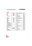
Manual No. ’03 - M - T - 078
MULTI-TYPE
PACKAGED AIR-CONDITIONER
(Split system, Air to air heat pump type)
(OUTDOOR UNIT)
FDCP808HES3, FDCP1008HES3
(INDOOR UNIT)
FDT208, 258, 308, 408, 508
FDR208, 258, 308, 408, 508
FDUR208, 258, 308, 408, 508
-
3-
CONTENTS
1. GENERAL INFORMATION ........................................................................... 1
1.1
Specific features .................................................................................... 1
1.2
How to read the model name ................................................................ 1
1.3
Table of models ...................................................................................... 2
1.4
Table of system combinations.............................................................. 2
2. SELECTION DATA ....................................................................................... 3
2.1
Specifications ........................................................................................ 3
2.2
Range of usage & limitations ............................................................... 12
2.3
Exterior dimensions .............................................................................. 14
2.4
Exterior appearance .............................................................................. 27
2.5
Piping system ........................................................................................ 28
2.6
Selection chart ....................................................................................... 30
2.7
Characteristic of fan .............................................................................. 32
2.8
Noise level .............................................................................................. 35
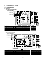
3. ELECTRICAL DATA ..................................................................................... 38
3.1
Electrical wiring ..................................................................................... 38
4. OUTLINE OF OPERATION CONTROL BY MICROCOMPUTER ................ 40
5. APPLICATION DATA .................................................................................... 52
5.1
Installation of indoor unit ..................................................................... 53
5.2
Installation of remote controller (Optional parts) ............................... 69
5.3
Installation of outdoor unit ................................................................... 70
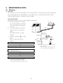
6. MAINTENANCE DATA ................................................................................. 78
6.1
Servicing ................................................................................................. 78
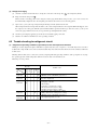
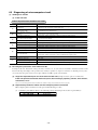
6.2
Trouble shooting for refrigerant circuit ............................................... 79
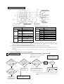
6.3
Diagnosing of microcomputer circuit .................................................. 80
-
1-
1
GENERAL INFORMATION
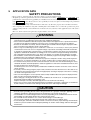
1.1 Specific features
Ideal for the installation conditions characteristic of larger rooms and L-shaped or other non-standard-shaped rooms, the Multi-Type V
series allows an extensive degree of flexibility in the selection of indoor units. Specifically, the selection of indoor units with differing
capacities and differing or similar types is supported, as is the selection of indoor units with similar capacities and differing types.
Furthermore, a maximum of up to four individual indoor units can be operated in synchrony with a single outdoor unit.
(1)
Simaltaneous operation possible in non-standard-shaped rooms or large-sized areas.
(2)
Select indoor units of differing capacities and differing or similar types; alternatively, indoor units of similar capacities and differing types.
(3)
Up to four individual indoor units can be connected to single outdoor unit.
(4)
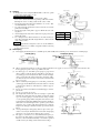
Indoor unit.
(i)
Ceiling recessed type (FDT)
(a)
All air supply ports have auto swing louvers. The indoor fan motor has two speeds of high and low.
(b) 700mm high drain head
Adoption of drain pump with high drain head and high capacity (600cc/min) has made it possible to have maximum
700 mm(from below ceiling drain head.[In case 700mm drain head is required, set it up close to the unit. It is
impossible to do piping on down slope.]
(ii)
Cassetteria type (FDR)
(a) 2 types of optional decorative panel
1) Optional decorative panel consists of silent panel and a canvas duct panel. [has smaller sizes and is prepared with
canvas duct panel which provides higher drain head.]
2) Flexibility of installation is increased with 2 type panels.
(iii) Ceiling mounted duct type (FDUR)
(a) The position of the suction port can be changed.
The suction from the lower inlet is available by replacing the duct connecting section (at the side face) and the lower
plate. (They are changed on site.)
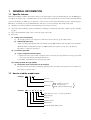
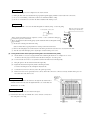
1.2 How to read the model name
Example: FDT
20 8 - A
Series No.
Nominal capacity
Model name
Example: FDC
P 80
8
H
ES
FDT: Ceiling recessed type
FDR: Cassetteria type
FDUR: Ceiling mounted duct type
3
Applicable power source ... See the specifications
Heat pump type
Series No.
Nominal capacity
R407C model
Model name (FDC: Outdoor unit)
-1-
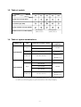
1.3 Table of models
Capacity
Model
208
258
308
408
508
Ceiling recessed type (FDT)
Cassetteria type (FDR)
Ceiling mounted duct type (FDUR)
Outdoor unit to be combined(FDC)
FDCP808HES3
(8 Horse Power)
FDCP1008HES3
(10 Horse Power)
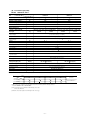
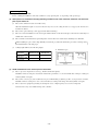
1.4 Table of system combinations
Outdoor unit
Type
Indoor unit assembly capacity
Branch pipe set
(Optional)
408+408
Twin
DIS-WB
308+508
FDCP808HES3
Triple
308+308+308
Double twin
208+208+208+208
DIS-TB
DIS-WAº2set
DIS-WBº1set
Twin
508+508
DIS-WB
208+408+408
Triple
258+258+508
DIS-TB
FDCP1008HES3
308+308+408
Double twin
258+258+258+258
DIS-WAº2set
DIS-WBº1set
Notes (1) It is possible to used different models (FDT, FDR, FDUR) when combining indoor units.
(2) Always use the branch piping set (optional) at branches in the refrigerant piping.
-2-
2
SELECTION DATA
2.1 Specifications
(1) Indoor unit
(a)
Ceiling recessed type (FDT)
Models FDT208-A, 258-A
Model
FDT208-A
FDT258-A
W
5000
5700
W
5400
Item
(1)
Nominal heating capacity(1)
Nominal cooling capacity
6100
Power source
1 Phase 220/240V 50Hz
dB(A)
Noise level
Exterior dimensions
Height
Width
Depth
Net weight
Hi: 39 Lo: 35
Hi: 38 Lo: 33
Unit:215
Panel:26
mm
kg
700
800
Unit:260
Panel:30
700
800
840
950
840
950
30(Unit:24 Panel:6)
23(Unit:18 Panel:5)
Refrigerant equipment
Heat exchanger
Louver fine & inner grooved tubing
Refrigerant control
Capillary tube
Air handling equipment
Fan type & Q'ty
Turbo fan 1
Motor
W
30 1
25 1
Starting method
Line starting
Air flow(Standard)
Hi: 14 Lo: 10
CMM
Hi: 16 Lo: 11
Fresh air intake
Available
Air filter, Q'ty
Long life filter
Shock & vibration absorber
1(Washable)
Rubber sleeve(for fan motor)
Operation control
Operation switch
Remote control switch (Optional:RCD-H-S-E)
Room temperature control
Thermostat by electronics
Internal thermostat for fan motor.
Frost protection thermostat
Safety equipment
Installation data
Refrigerant piping size
Liquid line: 6.35 (1/4")
Gas line: 15.88 (5/8")
mm(in)
Liquid line: 9.52 (3/8")
Gas line: 15.88 (5/8")
Flare piping
Connecting method
Connectable with VP25
Drain hose
Necessary (both Liquid & Gas line)
Insulation for piping
Mounting kit, Drain hose
Accessories
Decorative Panel
Optional parts
Notes (1) The data are measured at the following conditions.
Item
Indoor air temperature
Outdoor air temperature
DB
WB
DB
WB
Cooling
27
19
35
24
Heating
20
7
6
Operation
(2) This packaged air-conditioner is manufactured and tested in conformity with the following standard.
ISO-T1"UNITARY AIR-CONDITIONERS"
Decorative Panel model (Optional)
Item
Model
Panel Part No.
FDT208-A
T-PSA-22W-E
FDT258-A
T-PSA-32W-E
-3-
Standards
ISO-T1,JIS B8616
Models FDT308-A, 408-A, 508-A
Model
FDT308-A
FDT408-A
W
7100
10000
12500
W
8000
11200
14000
dB(A)
Hi: 41 Lo: 35
Item
(1)
Nominal heating capacity(1)
Nominal cooling capacity
Power source
FDT508-A
1 Phase 220/240V 50Hz
Noise level
Exterior dimensions
Height
Width
Depth
Unit:260
Panel:30
mm
Net weight
kg
840
950
Hi: 48 Lo: 40
840
950
Hi: 49 Lo: 43
Unit:320
Panel:30
30(Unit:24 Panel:6)
34(Unit:28 Panel:6)
Refrigerant equipment
Heat exchanger
Louver fine & inner grooved tubing
Refrigerant control
Capillary tube
Air handling equipment
Fan type & Q'ty
840
950
840
950
36(Unit:30 Panel:6)
Turbo fan 1
Motor
30 1
W
80 1
Starting method
130 1
Line starting
Air flow(Standard)
Hi: 17 Lo: 12
CMM
Hi: 26 Lo: 19
Fresh air intake
Hi: 28 Lo: 20
Available
Air filter, Q'ty
Long life filter
Shock & vibration absorber
1(Washable)
Rubber sleeve(for fan motor)
Operation control
Operation switch
Remote control switch (Optional:RCD-H-S-E)
Room temperature control
Thermostat by electronics
Internal thermostat for fan motor.
Frost protection thermostat
Safety equipment
Installation data
Refrigerant piping size
Liquid line: 9.52 (3/8")
Gas line: 15.88 (5/8")
mm(in)
Liquid line: 9.52 (3/8")
Gas line: 19.05 (3/4")
Flare piping
Connecting method
Connectable with VP25
Drain hose
Necessary (both Liquid & Gas lines)
Insulation for piping
Mounting kit, Drain hose
Accessories
Decorative Panel
Optional parts
Notes (1) The data are measured at the following conditions.
Item
Indoor air temperature
Outdoor air temperature
DB
WB
DB
WB
Cooling
27
19
35
24
Heating
20
7
6
Operation
(2) This packaged air-conditioner is manufactured and tested in conformity with the following standard.
ISO-T1"UNITARY AIR-CONDITIONERS"
Decorative Panel model (Optional)
Item
Model
FDT308-A, 408-A, 508-A
Panel Part No.
T-PSA-32W-E
-4-
Standards
ISO-T1,JIS B8616
(b) Cassetteria type (FDR)
Models FDR208-A, 258-A
Model
FDR208-A
Item
Decorative panel
Panel model (Option)
FDR258-A
Silent panel
Canvas panel
Silent panel
Canvas panel
R-PNLS-26W-E
R-PNLC-26W-E
R-PNLS-36W-E
R-PNLC-36W-E
Nominal cooling capacity(1)
W
5000
Nominal heating capacity(1)
W
5400
5700
6100
Power source
1 Phase 220/240V 50Hz
dB(A)
Noise level
Exterior dimensions
Height
Width
Depth
Net weight
mm
kg
Hi: 43 Lo: 37
Hi: 44 Lo: 38
Hi: 43 Lo: 37
Hi: 44 Lo: 38
Unit:355 750 635
Unit:(299+α) 750 635 Unit:355 950 635
Unit:(299+α) 950 635
Panel:10 1040 750 Panel:10 864 585
Panel:10 1240 750 Panel:10 1064 585
Unit:30
Panel:7
Unit:30
Panel:5
Unit:35
Panel:8
Refrigerant equipment
Heat exchanger
Louver fins & inner grooved tubing
Refrigerant control
Capillary tube
Air handling equipment
Fan type & Q'ty
Unit:35
Panel:6
Multiblade centrifugal fan 2
Motor
55 1
W
90 1
Starting method
Line starting
Air flow(Standard)
Available static pressure
CMM
Hi: 14 Lo: 11
Hi: 18 Lo: 14
Pa
Standard:50, High:85
Standard:45, High:80
Fresh air intake
Available
Air filter Q'ty
Polypropylene net 2(Washable)
Shock & vibration absorber
Rubber sleeve(for fan motor)
Operation control
Operation switch
Remote control switch (Optional:RCD-H-E)
Room temperature control
Thermostat by electronics
Internal thermostat for fan motor.
Frost protection thermostat
Safety equipment
Installation data
Refrigerant piping size
Liquid line: 6.35 (1/4")
Gas line: 15.88 (5/8")
mm(in)
Liquid line: 9.52 (3/8")
Gas line: 15.88 (5/8")
Flare piping
Connecting method
Connectable with VP25
Drain hose
Necessary (both Liquid & Gas lines)
Insulation for piping
Mounting kit, Drain hose
Accessories
Silent panel, Canvas panel, Canvas duct
Optional parts
Notes (1)The data are measured at the following conditions.
Item
Indoor air temperature
Outdoor air temperature
DB
WB
DB
WB
Cooling
27
19
35
24
Heating
20
7
6
Operation
(2)This packaged air-conditioner is manufactured and tested in conformity with the following standard.
ISO-T1"UNITARY AIR-CONDITIONERS"
(3)Canvas panel is used in combination with following canvas duct
Canvas duct: HA01503
(4)Add the canvas duct lenght to the unit height for the canvas type.
-5-
Standards
ISO-T1,JIS B8616
Models FDR308-A, 408-A
Model
FDR308-A
Item
Decorative panel
Panel model (Option)
FDR408-A
Silent panel
Canvas panel
Silent panel
Canvas panel
R-PNLS-36W-E
R-PNLC-36W-E
R-PNLS-46W-E
R-PNLC-46W-E
Nominal cooling capacity(1)
W
7100
Nominal heating capacity(1)
W
8000
10000
11200
Power source
1 Phase 220/240V 50Hz
dB(A)
Noise level
Exterior dimensions
Height
Width
Depth
mm
Net weight
kg
Hi: 44 Lo: 38
Hi: 45 Lo: 39
Hi:45 Lo: 38
Unit:35
Panel:8
Unit:35
Panel:6
Unit:50
Panel:9
Refrigerant equipment
Heat exchanger
Louver fins & inner grooved tubing
Refrigerant control
Capillary tube
Air handling equipment
Fan type & Q'ty
Multiblade centrifugal fan
Motor
Hi: 46 Lo: 39
Unit:(299+α) 950 635 Unit:406 1370 635 Unit:(350+α) 1370 635
Unit:355 950 635
Panel:10 1660 750 Panel:10 1484 585
Panel:10 1240 750 Panel:10 1064 585
W
2
Unit:50
Panel:7
Multiblade centrifugal fan
45 1+90 1
100 1
Starting method
Line starting
Air flow(Standard)
CMM
Hi: 20 Lo: 15
Hi: 28 Lo: 22
Pa
Standard:45, High:80
Standard:50, High:80
Available static pressure
Fresh air intake
Available
Air filter Q'ty
Polypropylene net 2(Washable)
Shock & vibration absorber
Polypropylene net 3(Washable)
Rubber sleeve(for fan motor)
Operation control
Operation switch
Remote control switch (Optional:RCD-H-E)
Room temperature control
Thermostat by electronics
Internal thermostat for fan motor.
Frost protection thermostat
Safety equipment
Installation data
Refrigerant piping size
Liquid line: 9.52 (3/8")
Gas line: 15.88 (5/8")
mm(in)
Liquid line: 9.52 (3/8")
Gas line: 19.05 (3/4")
Flare piping
Connecting method
Connectable with VP25
Drain hose
Necessary (both Liquid & Gas lines)
Insulation for piping
Mounting kit, Drain hose
Accessories
Silent panel, Canvas panel, Canvas duct
Optional parts
Notes (1)The data are measured at the following conditions.
Item
Indoor air temperature
Outdoor air temperature
DB
WB
DB
WB
Cooling
27
19
35
24
Heating
20
7
6
Operation
3
(2)This packaged air-conditioner is manufactured and tested in conformity with the following standard.
ISO-T1"UNITARY AIR-CONDITIONERS"
(3)Canvas panel is used in combination with following canvas duct
Canvas duct: HA01503
(4)Add the canvas duct lenght to the unit height for the canvas type.
-6-
Standards
ISO-T1,JIS B8616
Model
FDR508-A
Model
FDR508-A
Item
Decorative panel
Panel model (Option)
Nominal cooling capacity(1)
W
Nominal heating capacity(1)
W
Silent panel
Canvas panel
R-PNLS-46W-E
R-PNLC-46W-E
12500
14000
Power source
1 Phase 220/240V 50Hz
Noise level
Exterior dimensions
Height
Width
Depth
Net weight
dB(A)
Hi: 46 Lo: 39
mm
Unit:406 1370 635
Panel:10 1660 750
kg
Unit:52
Panel:9
Hi: 47 Lo: 40
Unit:(350+α) 1370 635
Panel:10 1484 585
Unit:52
Panel:7
Refrigerant equipment
Heat exchanger
Louver fins & inner grooved tubing
Refrigerant control
Capillary tube
Air handling equipment
Fan type & Q'ty
Multiblade centrifugal fan
Motor
W
3
50 1+100 1
Starting method
Line starting
Air flow(Standard)
Available static pressure
CMM
Hi: 34 Lo: 27
Pa
Standard:50, Hi speed:80
Fresh air intake
Available
Air filter Q'ty
Polypropylene net 3(Washable)
Shock & vibration absorber
Rubber sleeve(for fan motor)
Operation control
Operation switch
Remote control switch (Optional:RCD-H-E)
Room temperature control
Thermostat by electronics
Internal thermostat for fan motor.
Frost protection thermostat
Safety equipment
Installation data
Refrigerant piping size
Liquid line: 9.52 (3/8")
Gas line: 19.05 (3/4")
mm(in)
Flare piping
Connecting method
Connectable with VP25
Drain hose
Necessary (both Liquid & Gas lines)
Insulation for piping
Mounting kit, Drain hose
Accessories
Silent panel, Canvas panel, Canvas duct
Optional parts
Notes (1)The data are measured at the following conditions.
Item
Indoor air temperature
Outdoor air temperature
DB
WB
DB
WB
Cooling
27
19
35
24
Heating
20
7
6
Operation
(2)This packaged air-conditioner is manufactured and tested in conformity with the following standard.
ISO-T1"UNITARY AIR-CONDITIONERS"
(3)Canvas panel is used in combination with following canvas duct
Canvas duct: HA01484
(4)Add the canvas duct lenght to the unit height for the canvas type.
-7-
Standards
ISO-T1,JIS B8616
(c)
Ceiling mounted duct type (FDUR)
Models FDUR208-A, 258-A
Model
FDUR208-A
FDUR258-A
W
5000
5700
W
5400
Item
(1)
Nominal heating capacity(1)
Nominal cooling capacity
6100
Power source
1 Phase 220/240V 50Hz
dB(A)
Noise level
Exterior dimensions
Height
Width
Depth
Net weight
Hi: 40 Lo: 36
Hi: 41 Lo: 37
mm
295
kg
850 650
39
40
Refrigerant equipment
Heat exchanger
Louver fins & inner grooved tubing
Refrigerant control
Capillary tube
Air handling equipment
Fan type & Q'ty
Multiblade centrifugal fan
Motor
W
2
90 1
130 1
Starting method
Line starting
Air flow(Standard)
CMM
Hi: 17 Lo: 13.5
Hi: 21 Lo: 17
Pa
Available static pressure
Standard:50, Max:85
Fresh air intake
-
Air filter Q'ty
Polypropylene net 1(Washable)
Shock & vibration absorber
Rubber sleeve(for fan motor)
Operation control
Operation switch
Remote control switch (Optional:RCD-H-E)
Room temperature control
Thermostat by electronics
Internal thermostat for fan motor.
Frost protection thermostat
Safety equipment
Installation data
Refrigerant piping size
Liquid line: 6.35 (1/4")
Gas line: 15.88 (5/8")
mm(in)
Liquid line: 9.52 (3/8")
Gas line: 15.88 (5/8")
Flare piping
Connecting method
Connectable with VP25
Drain hose
Necessary (both Liquid & Gas lines)
Insulation for piping
Mounting kit, Drain hose
Accessories
Silent panel
Optional parts
Notes (1)The data are measured at the following conditions.
Item
Indoor air temperature
Outdoor air temperature
DB
WB
DB
WB
Cooling
27
19
35
24
Heating
20
7
6
Operation
Standards
ISO-T1,JIS B8616
(2)This packaged air-conditioner is manufactured and tested in conformity with the following standard.
ISO-T1"UNITARY AIR-CONDITIONERS"
Silent Panel model (Optional)
Item
Model
FDUR208-A, 258-A
Panel Part No.
Color
UR-PS-27W-E
Ceramic white
-8-
Models FDUR308-A, 408-A, 508-A
Model
FDUR308-A
FDUR408-A
FDUR508-A
W
7100
10000
12500
W
8000
11200
14000
Item
(1)
Nominal heating capacity(1)
Nominal cooling capacity
Power source
1 Phase 220/240V 50Hz
Hi: 41 Lo: 37
dB(A)
Noise level
Exterior dimensions
Height
Width
Depth
Net weight
mm
295
850
Hi: 44 Lo: 40
350
650
40
kg
Hi: 45 Lo: 41
1370
63
65
Refrigerant equipment
Heat exchanger
Louver fine & inner grooved tubing
Refrigerant control
Capillary tube
Air handling equipment
Fan type & Q'ty
Multiblade centrifugal fan
W
230 1
280 1
CMM
Hi: 25 Lo: 20
Hi: 34 Lo: 27
Motor
650
Starting method
1
460 1
Line starting
Air flow(Standard)
Hi: 42 Lo: 33.5
Standard: 50, Max: 130
Pa
Available static pressure
Fresh air intake
-
Air filter, Q'ty
Polypropylene net
Shock & vibration absorber
1(Washable)
Rubber sleeve(for fan motor)
Operation control
Operation switch
Remote control switch (Optional:RCD-H-E)
Room temperature control
Thermostat by electronics
Internal thermostat for fan motor.
Frost protection thermostat
Safety equipment
Installation data
Refrigerant piping size
Liquid line: 9.52 (3/8")
Gas line: 15.88 (5/8")
mm(in)
Liquid line: 9.52 (3/8")
Gas line: 19.05 (3/4")
Flare piping
Connecting method
Connectable with VP25
Drain hose
Necessary (both Liquid & Gas lines)
Insulation for piping
Mounting kit, Drain hose
Accessories
Silent Panel
Optional parts
Notes (1) The data are measured at the following conditions.
Item
Indoor air temperature
Outdoor air temperature
DB
WB
DB
WB
Cooling
27
19
35
24
Heating
20
7
6
Operation
Standards
ISO-T1,JIS B8616
(2) This packaged air-conditioner is manufactured and tested in conformity with the following standard.
ISO-T1"UNITARY AIR-CONDITIONERS"
Silent Panel model (Optional)
Item
Model
Panel Part No.
FDUR308-A
UR-PS-27W-E
FDUR408-A, 508-A
UR-PS-47W-E
Color
Ceramic white
-9-
(2)
Outdoor unit
Models FDCP808HES3, 1008HES3
Model
Item
FDCP808HES3
FDCP1008HES3
3 Phase 380/415V 50Hz
Power source
Nominal cooling capacity(1)
W
20000
25000
Nominal heating capacity(1)
W
22400
28000
Noise level
Exterior dimensions
Height
Width
Depth
Net weight
mm
kg
Refrigerant equipment
compressor type & Q' ty
Motor
58
dB(A)
1450
205
1
CB125H
Line starting
W
70
Slitted fines & bare tubing
Heat exchanger
Refrigerant control
Capillary tube
Refrigerant
Quantity
R407C
kg
4.95(Pre-charged up to the piping length of 5m)
Refrigerant oil
MC controlled De-Icer
Air handling equipment
Fan type & Q'ty
Propeller fan 2
100 2
W
Starting method
Air flow(Standard)
Line starting
CMM
180
Shock & vibration absorber
Rubber mount (for compressor)
Internal thermostat for fan motor.
High pressure protection switch
Safety equipment
Installation data
Refrigerant piping size
Connecting method
7.1(Pre-charged up to the piping length of 5m)
4.4 (MA32R)
Defrost control
Motor
1
9.0
6.5
Starting method
Crankcase heater
600
195
CB90H
kW
1350
mm(in)
Liquid line: 12.7 (1/2")
Gas line: 25.4 (1")
Liquid line: 15.88 (5/8")
Gas line: 28.58 (11/8")
Liquid line: Flare piping Gas line: Brazing
Drain
Hole for drain( 20 8pcs, 50 1pcs)
Insulation for piping
Necessary (both Liquid & Gas lines)
_
Accessories
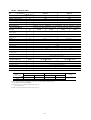
Notes (1) The cooling and heating capabilities imply the values when the indoor unit of rated capacity is connected under the condition specified in ISO-T1.
(2) The refrigerant quantity in the connecting pipe is not included Charge it additionally at the site.
- 10 -
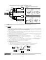
(3) Operation chart
Regarding the operation characteristics of the twin unit of the same model and with the same capacity, please refer to the nameplate
on the equipment.
For any other combinations (Twin, triple or double-twin of different models and different capacities), please calculate based on the
following operaion characteristics. (See page 12.)
(a) Operating characteristic of outdoor unit
(380 V/415 V)
Model
Item
FDCP808HES3
FDCP1008HES3
8.20/8.38
12.36/12.42
7.78/7.86
11.22/11.43
13.3/13.5
19.8/18.9
12.6/12.8
18.6/17.9
Cooling input
kW
Heating input
Cooling running current
A
Heating running current
Inrush current (L.R.A)
A
Cooling power factor
%
Heating power factor
99
154
94/86
95/91
94/85
92/89
Note (1) This packaged air-conditioner is manufactured and tested in conformity with the following standard.
ISO-T1 “UNITARY AIR-CONDITIONERS”
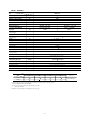
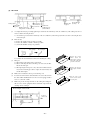
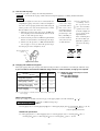
(b) Operating characteristic of indoor unit
FDT Series
Model
Item
(220 V/240 V)
FDT Series
208-A
Power input (kW)
308-A
408-A
508-A
0.10/0.11
0.11/0.12
0.21/0.21
0.27/0.27
0.5/0.5
0.6/0.6
1.2/1.2
1.4/1.4
Running current (A)
258-A
FDR Series
(220 V/240 V)
Model
Item
Power input (kW)
FDR Series
208-A
258-A
308-A
408-A
508-A
0.10/0.11
0.11/0.12
0.15/0.16
0.19/0.19
0.24/0.24
0.7/0.7
0.9/0.9
1.2/1.2
Running current (A)
0.5/0.5
FDUR Series
(220 V/240 V)
Model
Item
Power input (kW)
Running current (A)
FDUR Series
208-A
258-A
308-A
408-A
508-A
0.18/0.19
0.20/0.22
0.23/0.24
0.33/0.37
0.40/0.45
0.9/0.9
1.0/1.0
1.1/1.3
1.5/1.7
1.8/2.0
Notes (1) This packaged air-conditioner is manufactured and tested in conformity with the following standard.
ISO-T1 “UNITARY AIR-CONDITIONERS”
(2) The values shown in the above table are common to both cooling and heating operations.
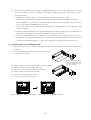
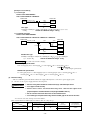
(c) Calculation of total operation characteristics
Since the operation characteristics of series Multi depend on combination of indoor unit, calculate the total operation
characteristics of the system by using the formulas below according to specifications of each indoor unit or outdoor unit.
1) Total power input
Total power input (kW) = Power input of outdoor unit + ∑ (Power input of indoor unit)
2) Total running current
Total running current (A) = Running current of outdoor unit + [∑ (Running current of indoor unit) × 2/3]
- 11 -
3) Total power factor
—
Total power factor (%) = [Total power input (W) / √ 3 × Total running current (A) × Power source] × 100
Total operation characteristics = Operation characteristic value of outdoor unit + Operation characteristic value of indoor unit
[Example]
(Conditions)
Operation Voltage ········ Indoor unit: 220 V, 50 Hz
Outdoor unit: 380 V, 50 Hz
Operation mode ··········· Cooling and Heating
Unit·······························Outdoor unit: FDCP808HES3 × 1 unit
Indoor unit: FDUR308-A × 1 units, FDT508-A × 1 units
Operation characteristics of each unit
Model
(Cooling/Heating)
FDCP808HES3
FDUR308-A
FDT508-A
Power input (kW)
8.20/7.78
0.23/0.23
0.27/0.27
Running current (A)
13.8/12.6
1.1/1.1
1.4/1.4
Item
1 Total power input (kW)
(Cooling) 8.20 + 0.23+ 0.27 = 8.70 (kW)
(Heating) 7.78 + 0.23+ 0.27 = 8.28 (kW)
2 Total running current (A)
2 .
(Cooling) 13.3 + (1.1+1.4 × 3 )=. 15.0 (A)
2
(Heating) 12.6 + (1.1 + 1.4 × 3 ).=. 14.3 (A)
3 Total power factor (%)
(Cooling)
8.70 × 1000
.
—
× 100 =. 88 %
√ 3 × 15.0 × 380
(Heating)
.
8.28 × 1000
× 100 =. 88 %
—
√ 3 × 14.3 × 380
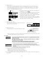
2.2 Range of usage & limitations
Model
Item
FDCP808HES3
FDCP1008HES3
Indoor return air temperature
(Upper, lower limits)
Refer to the selection chart
Outdoor air temperature
(Upper, lower limits)
Indoor unit atmosphere (behind ceiling)
temperature and humidity
Dew point temperature: 28˚C or less, relative humidity: 80% or less
Max. 50m(1)
Refrigerant line (one way) length
Vertical height difference between
outdoor unit and indoor unit
Max. 30m (Outdoor unit is higher)
Max. 15m (Outdoor unit is lower)
Max. 4m
Difference in height between indoor units
Rating ± 10%
Power source voltage
Min. 85% of rating
Voltage at starting
Frequency of ON-OFF cycle
Max. 10 times/h
ON and OFF interval
Max. 3 minutes
Note (1) Refer to the next page for details of common pipe length.
- 12 -
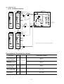
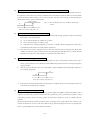
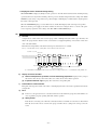
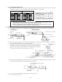
Height and length restrictions for refrigerant piping
Model FDCP808, 1008HES3
(Twin type)
Outdoor unit
L
(Double-twin type)
Outdoor unit
Indoor unit
ra
Indoor unit
rd
rc
rb
A
rb
B
ra
L
r1
rA
(Triple type)
Outdoor unit
L
r2
Indoor unit
ra
A
B
rB
rC
C
rD
D
A
rb
B
rc
C
In the illustration the L is main piping and ra, rb, rc, and rd are branch piping.
● One-way pipe length (m) L+ra ≤ 50, L+rb ≤ 50, L+rc ≤ 50, L+rd ≤ 50
● Branch pipe length (m)
ra -rb ≤ 10, ra -rc ≤ 10, rb -rc ≤ 10
ra -rd ≤ 10, rb -rd ≤ 10, rc -rd ≤ 10
ra ≤ 30, rb ≤ 30, rc ≤ 30, rd ≤ 30
rA +rB ≤ 15, rC +rD ≤ 15
● Vertical height difference between outdoor unit and indoor unit
Outdoor unit is higher Max. 30m
Outdoor unit is lower Max. 15m
● Difference in higher between indoor units Max. 4m
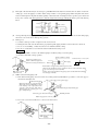
Request
(1)
When the capacity of the indoor unit to be connected is 208 or less, be sure to use a pipe diameter of ø9.52 for the size of the
liquid piping of branch piping (between branch and indoor units). (for twin, triple, and double-twin only) For connections to
indoor units (liquid piping side dai. ø6.35) use the different diameter adapter coupling that is included in the branch piping
kit.
(2)
For the branch be sure to select the specified branch pipe set (sold separately) and then to follow the directions of the
instruction manual included in the branch pipe set when installing the piping. Be sure to install the branch piping so that the
branch is level.
- 13 -
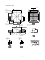
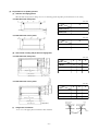
2.3 Exterior dimensions
(1) Indoor unit
(a)
Ceiling recessed type (FDT)
Model FDT208-A
Unit : mm
740 (Ceiling hole size)
Decorative Panel
430
Fresh air opening
for ducting
800
(Suspension bolts
pitch)
C
515
→
680 (Suspension bolts pitch)
Exhaust air opening
for ducting
→
295
359
336
D
570
B→
264
700
VIEW A
Gas piping
φ15.88(5/8")
→
Hole for wiring
A
215
141
99
49
or more
295 ~ 325
Liquid piping
φ6.35(1/4")
26
Suspension bolts
(M10 or M8)
VIEW B
Lug for Suspension bolts
Control box
Holes for
tapping screws
Holes for
tapping screws
37
70
VIEW C
120
VIEW D
- 14 -
100
80
110
90
90
87
50
Space for installation and service
4-φ4 140
35
4-φ4
1000
or more
161
Air outlet grille
700 or more
Drain hose(Accessories)
(Connectable with VP25)
Air inlet grille
304
(Max. Drain up)
300
Obstacle
1000
or more
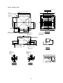
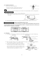
Models FDT258-A, 308-A
Unit : mm
Decorative Panel
Fresh air
opening for ducting
↑
C
860~890 (Ceiling hole size)
950
780 (Suspension bolts pitch )
630
400
420
637
D→
422
675 (Suspension bolts pitch)
Exhaust air
opening for ducting
B→
Air inlet grille
267
Drain hose (Accessories)
(Connectable with VP25)
332
310
VIEW A
Air outlet grille
Liquid piping
φ9.52(3/8")
840
↑
A
Hole for wiring
Control box
260
700 or less
(Max. Drain up)
295~325
30
137
95
VIEW B
Holes for
tapping screws
6-φ4
Holes for
tapping screws
4-φ4
55
140
25
Space for installation and service
80
VIEW C
1000
42
140
112
100
113
140
160
33
60
Obstacle
VIEW D
- 15 -
or more
210
45 or more
Lug for
suspension bolts
187
Suspension bolts
(M10 or M8 ×4pcs.)
Gas piping
( φ15.88)
1000
or more
Models FDT408-A, 508-A
Unit : mm
Decorative Panel
Fresh air
opening for ducting
↑
C
860~890 (Ceiling hole size)
950
780 (Suspension bolts pitch )
630
400
420
637
D→
422
675 (Suspension bolts pitch)
Exhaust air
opening for ducting
B→
Air inlet grille
267
Drain hose (Accessories)
(Connectable with VP25)
332
310
VIEW A
Air outlet grille
Liquid piping
φ9.52(3/8")
840
↑
A
Hole for wiring
Control box
320
700 or less
(Max. Drain up)
295~325
30
137
95
VIEW B
Holes for
tapping screws
6-φ4
Holes for
tapping screws
4-φ4
55
140
25
Space for installation and service
80
VIEW C
1000
42
140
112
100
113
140
160
93
60
Obstacle
VIEW D
- 16 -
or more
270
45 or more
Lug for
suspension bolts
187
Suspension bolts
(M10 or M8 ×4pcs.)
Gas piping
φ19.05(3/4")
1000
or more
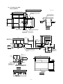
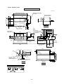
(b) Cassetteria type (FDR)
Model FDR208-A
Silent Panel (Model: R-PNLS-26W-E)
Unit : mm
980 (Ceiling hole size)
57
786 (Suspension bolts pitch)
433
Drain hose (Accessories)
137
(Locality)
353
Fresh air opening
(Knock out hole)
284
71
150
480
465
405
102
81
↑A
213
MIN320
0
φ20
Drain (Natural drainage)
(VP20)
Hole of wiring
(I.D. φ35)
250
460
213
Holes of
tapping screws
4-φ 4.0
1040
150
45
45
950
45
Air inlet
φ170
75
205
φ149
φ170
510
Exhaust air opening for ducting
(Knock out for ducting)
100 or
more
or more
100 or
more
Air inlet
50 or
more
VIEW A
Obstacle
- 17 -
75
Space for installation and service
45
VIEW B
750
90
Fresh air opening
for ducting
(Knock out hole)
1000
232
B→
Hole for
humidifier piping
(I.D. φ14)
650
355~369
245
510
40
320
635
80
163
185
Liquid piping
φ6.35 (1/4")
295~325
750
VIEW C
Drain
(Connectable with VP25)
Gas piping
φ15.88 (5/8")
Suspension bolts
(M10 × 4pcs.)
405
(Max. Drainup)
Air outlet duct
(Suspension bolt pitch)
545
45
Panel center
690 (Ceiling hole size)
270
Control box
75
45
275
59
70
69
C↓
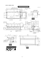
Model FDR208-A
Canvas Panel (Model: R-PNLC-26W-E)
Drain hose (Accessories)
804 (Ceiling hole size)
9
Unit : mm
786 (Suspension bolts pitch)
(Local Locality)
9
45
150
193
Drain
(Connectable with VP25)
Control box
352
Panel center
Liquid piping
φ6.35 (1/4")
405
VIEW C
59
Air outlet duct
71
295~325
750
320
245
480
Hole for humidifier piping
(I.D.φ14)
465
405
Drain
(Connectable
with VP25)
260
199
B→
274
299
600
35
635
510
149
185
80
40
Suspension bolts
(M10 × 4pcs.)
(Max. Drain up)
Gas piping
φ15.88 (5/8")
130
0
φ20
Hole of
wiring
(I.D.φ35)
150~
300
Canvas duct
(Optional parts)
↑A
Drain (Natural drainage)
(VP20)
250
460
205
213
φ149
864
φ170
Fresh air
opening for ducting
(Knock out hole)
75
Air inlet
φ170
45
75
774
45
45
45
150
Holes of tapping screws
4-φ4.0
345
Exhaust air opening for ducting
(Knock out hole)
VIEW B
100 or
more
or more
Space for installation and service
100 or
50 or
more
more
Air inlet
VIEW A
Obstacle
- 18 -
585
90
1000
525 (Ceiling hole size)
90
Fresh air opening
(Knock out hole)
69
45
545 (Suspension bolts pitch) 70
284
C↓
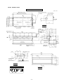
Models FDR258-A, 308-A
Unit : mm
Silent Panel (Model: R-PNLS-36W-E)
1180 (Ceiling hole size)
986 (Suspension bolts pitch)
57
533
137
453
Drain hose (Accessories)
(Locality)
Fresh air opening
(Knock out hole)
45
285
150
VIEW C
(Max. Drain up)
295~325
950
165
500
71
Air outlet duct
Suspension bolts
(M10 × 4pcs.)
690 (Ceiling hole size)
45
545
270
Control box
Panel center
(Suspension bolts pitch)
275
59
75
69
C↓
70
284
285
215
635
510
480
465
Hole for
humidifier piping
(I.D.φ14)
405
40
B→
80
φ20
102
163
650
355~369
460
Holes of
tapping screws
4-φ4.0
1240
1150
150
45
Air inlet
45
45
213
205
φ149
Hole
of wiring
(I.D.φ35)
250
75
Drain (Natural drainage)
(VP20)
Liquid piping
φ9.52 (3/8")
Gas piping
φ15.88 (5/8")
81
↑A
213
232
MIN320
0
φ170
φ170
Fresh air opening
for ducting
(Knock out hole)
510
Exhaust air opening for ducting
(Knock out hole)
VIEW B
or more
1000 or
100
more
100 or
more
Obstacle
VIEW A
- 19 -
45
Air inlet
50 or
more
75
Space for installation and service
750
90
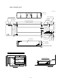
Models FDR258-A, 308-A
Canvas Panel (Model: R-PNLC-36W-E)
Unit : mm
Drain hose (Accessories)
(Locality)
1004 (Ceiling hole size)
986 (Suspension bolts pitch)
Fresh air opening
(Knock out hole)
45
150
193
69
352
Panel center
Control box
500
VIEW C
59
950
285
285
215
635
510
Hole for
humidifier piping
(I.D.φ14)
480
465
405
Drain
(Connectable
with VP25)
199
260
B→
274
299
35
600
149
165
295~325
80
40
Suspension bolts
(M10 × 4pcs.)
(Max. Drain up)
71
Air outlet duct
130
Drain (Natural drainage)
(VP20)
Canvas duct
(Optional Parts)
150~300
0
φ20
Gas piping
φ15.88 (5/8")
Hole
of wiring
(I.D.φ35)
Liquid piping
φ9.52 (3/8")
↑A
250
460
1064
φ149
45
974
Air inlet
45
345
φ170
90
Air inlet
VIEW B
VIEW A
100
or more
1000
Space for installation and service
100
or more
50
or more
Obstacle
- 20 -
75
Exhaust air opening for ducting
(Knock out hole)
45
φ170
Fresh air
opening for ducting
(Knock out hole)
585
150
Holes of tapping screws
4-φ4.0
75
213
45
205
or more
525 (Ceiling hole size)
90
9
284
C↑
45
545 (Suspension bolts pitch)
70
9
Models FDR408-A, 508-A
Silent Panel (Model: R-PNLS-46W-E)
Unit : mm
1600(Ceiling hole size)
Drain hose(Accessories)
1406(Suspension bolts pictch)
57
743
137
(Locality)
663
Fresh air opening
284
Air outlet duct
70
150
690(Ceiling hole size)
45
45
Panel center
545
(Suspension bolts pictch)
Control box
495
VIEW C
75
275
58
270
(Knock out hole)
69
C
76
80
320
320
235
(I.D.φ14)
405
81
406~420
B
650
MIN320
MIN276
φ20
0
465
103
320
480
40
175
295~325
213
1370
Drain
(Connectable
with VP25)
Hole for
humidifier piping
163
(M10 × 4 pcs.)
510
(Max.Drain up)
Suspension bolts
635
A
Hole of
wiring
155
Drain(Natural drainage)
Gas piping
φ19.05(3/4")
(VP20)
(I.D.φ35)
460
Liquid piping
φ9.52(3/8")
213
1660
φ170
45
1570
45
Air inlet
75
150
Hole of tapping screws
4 - φ4.0
45
205
φ149
(Knock out hole)
510
90
Exhaust air opening for ducting
(Knock out hole)
1000
100
or more
or more
VIEW A
100
or more
50
or more
Obstacle
- 21 -
75
Air inlet
Space for installation and service
45
VIEW B
750
φ170
Fresh air opening
for ducting
Models FDR408-A, 508-A
Canvas Panel (Model: R-PNLC-46W-E)
Unit : mm
Drain hose(Accessories)
1424(Ceiling hole size)
1406(Suspension bolts pictch)
9
Fresh air opening
(Locality)
9
(Knock out hole)
150
45
C
193
69
352
Panel center
Control box
495
VIEW C
59
71
Suspension bolts
80
1370
(M10 × 4 pcs.)
320
320
320
235
(I.D.φ14)
510
480
465
310
250
325
350
86
600
130
B→
635
405
200
175
295~325
Drain
(Connectable
with VP25)
Hole for
humidifier piping
40
Air outlet duct
(Max.Drain up)
0
150~300
φ20
Canvas duct
(Optional parts)
Drain(Natural drainage)
A
Hole of
wiring
(I.D.φ35)
Liquid piping
φ9.52(3/8")
(VP20)
155
460
213
1484
45
1394
Air inlet
φ170
45
75
150
Hole of tapping screws
4 - φ4.0
45
φ149
75
205
Gas piping
φ19.05(3/4")
45
φ170
Fresh air opening
for ducting
345
90
Exhaust air opening for ducting
(Knock out hole)
(Knock out hole)
VIEW B
Air inlet
Space for installation and service
1000
100
or more
or more
VIEW A
100
or more
50
or more
Obstacle
- 22 -
585
90
45 545(Suspension bolts pictch)
525(Ceiling hole size)
70
284
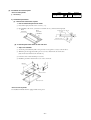
(c)
Ceiling mounted duct type
Models FDUR208-A, 258-A, 308-A
Unit : mm
Air inlet duct
(Low of suspension lug)
886 (Suspension bolts pitch)
850 (Duct for dimension)
45
560
(Suspension bolts pitch)
295
18
25
245
25
240
475
420
480
35
525
80
30
18
650
145
(Duct for dimension)
Control box
Suspension bolts
(M10 × 4pcs)
70
45
30
Liquid piping
ø9.52 (3/8”)
58
Air outlet duct
71
25
Gas piping
ø15.88 (5/8”)
Drain (Connectable
with VP25)
100
150
260
Drain (Natural drainage, VP20)
28
Space for installation and service
100
(Max.Drain up)
850
600
600
635
Drain hose(Accessories)
(Local Locality)
Air outlet
1720
Ceiling surface
Inspection hole
- 23 -
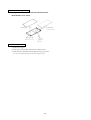
Models FDUR408-A, 508-A
Unit : mm
Air inlet duct
(Duct for dimension)
(Low of suspension lug)
Control box
Suspension bolts
(M10 × 4pcs)
173
1406 (Suspension bolts pitch)
1370 (Duct for dimension)
350
18
300
25
25
475
240
420
525
35
480
80
30
45
650
560
(Suspension bolts pitch)
18
70
25
58
45
30
Liquid piping
ø9.52 (3/8”)
77
100
Gas piping
ø19.05 (3/4”)
150
Air outlet duct
260
Drain (Connectable
with VP25)
Drain (Natural drainage, VP20)
28
Space for installation and service
100
(Max.Drain up)
850
600
600
635
Drain hose(Accessories)
(Local Locality)
Air outlet
1720
Ceiling surface
Inspection hole
- 24 -
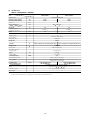
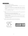
(2) Remote controller (Optional parts)
Unit : mm
Wall
0.3mm2, 3cores (O.D.φ5.6)
Wire
(Recessed)
LCD display
Junction box
(Locally Purchased)
120
16
Remote controller mounting dimensions
120
60
46
47
17
7
120
89
83.5
For the passage
after wiring
Note (1) Allowable length of remote controller
cable: 600 m
Allowable rang of wire thickness and length
Standard Within 0.3 mm2
0.5 mm2
0.75 mm2
1.25 mm2
2 mm2
Remote controller outline
- 25 -
× Within 100 m
× Within 200 m
× Within 300 m
× Within 400 m
× Within 600 m
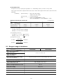
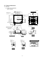
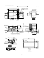
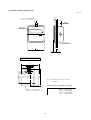
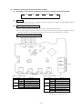
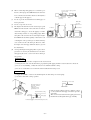
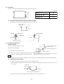
(3) Outdoor unit
Unit: mm
Models FDCP808HES3, 1008HES3
1350
Opening for
exit wiring
(ø50)
1450
50
600
A
Connect of liquid piping
808: ø12.7 (1/2")
1008: ø15.58 (5/8")
(
)
80
Power supply connecting
terminal block
170
105
105
119
20
291.5
Opening for
exit piping
(ø88)
Opening for
exit wiring
(ø50)
80
Connect of gas piping
170
ø25.4 (1")
( 1008:808:ø28.58
(1 1/8") )
250
Anchor bolts
(M10 × 4pcs.)
250
850
Downward outlet hole for
piping and wiring
157
767
395
169
81
15
40
Opening for
exit piping
(ø88)
15
123
640
532
Opening for
exit liquid
pipimg
(ø25)
702
283.5
283.5
135
Opening for
exit gas pipimg
(ø39)
157
567
Hole for drain
(8-ø20)
102
Hole for drain
(ø50)
22
29
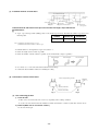
Dimentions of refrigerant piping
connecting mouth
(Front)
Wall Height H3
88
Wall height H1
123
50
110
175
240
Rear surface
Connect of liquid piping
808: ø12.7 (1/2")
1008: ø15.88 (5/8")
70
Connect of
gas piping
808: ø25.4 (1")
1008: ø28.58 (1 1/8")
(
)
100
(
)
Wall height H4
L4
L1
Wall height H2
L2
( Service
space )
Opening for exit
gas pipimg
(ø65)
L3
(Unit:mm)
suction
Opening for
exit liquid piping
(ø50)
Opening for
exit wiring
(ø35)
VIEW A
Installation
example
Dimensions
L1
L2
L3
L4
H1
H2
H3
H4
I
II
III
Open
0
Open
0
500
0
300
300
300
Open
500
0
1000 or less
Not limited Not limited Not limited
Not limited Not limited 700 or less
Not limited Not limited
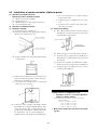
Notes (1) Make sure to secure the unit with anchor bolts.
(2) When the strong wind blows, place the unit so that discharge outlet
faces the wind direction with right angle.
(3) Make sure to allow the space of 1 m or more above the unit.
(4) Connect the refrigerant piping (both gas side and liquid side) at local
site.
(5) If the wall height H1, H3 of installation example III exceeds the limited value, make sure the value of L1, L3 are to be as follows.
L1 =H1 -500
L3 = 300 + (H3-700) / 2, however, if L3 exceeds 600, there is no limit
for the wall height H3.
110
175
- 26 -
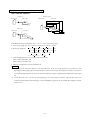
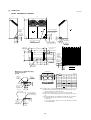
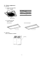
2.4 Exterior appearance
(1) Indoor unit
(a) Ceiling recessed type (FDT)
Models All models
Item
Type
Panel model
FDT208-A
T-PSA-22W-E
FDT258-A~508-A
T-PSA-32W-E
Pearl white
(Decorative panel)
(b) Cassetteria type (FDR)
Models All models
Canvas-duct panel type
Silent panel type
Ceramic White
Ceramic White
(2) Outdoor unit
Models FDCP808HES3, 1008HES3
Polar white
- 27 -
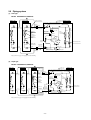
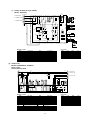
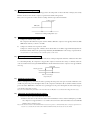
2.5 Piping system
(1) Twin type
Models FDCP808HES3,1008HES3
Indoor unit
Flare connecting
Indoor unit
Service valve
(Brazing)
Branch
pipe (Brazing)
Strainer
Strainer
308 : ø15.88
(408,508
: ø19.05)
308 : ø15.88
(408,508
: ø19.05)
Cooling cycle Outdoor unit
Heating cycle
High pressure switch(63H2)
(For fan motor control)
Thermistor
(ThO-A)
Gsa line
808 : ø25.4
(1008
: ø28.58 )
4way valve
High pressure
switch(63H1)
(For protection)
Thermistor
(ThI-A)
Heat
exchanger
Lower
Heat
exchanger
Upper
Muffler
Thermistor
(ThI-R)
Muffler
Compressor
Accumlator
Solenoid
Vaive (SV)
Thermistor (ThO-R)
Capillary tube
Capillary tube
Liquid line
(ø9.52)
808 : ø12.7
(1008
: ø15.88 )
(ø9.52)
Strainer
Strainer
Check valve
Service valve
(Flare connecting)
Branch
pipe
(Brazing)
Capillary tube
Note (1) Refer to page 72 for piping size after branching.
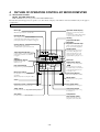
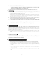
(2) Triple type
Models FDCP808HES3,1008HES3
Indoor unit
Indoor unit
Indoor unit
Cooling cycle
Heating cycle
Flare
connecting
Service valve
(Brazing)
High pressure switch(63H2)
(For fan motor control)
Outdoor unit
Thermistor
(ThO-A)
Branch
pipe(Brazing)
Strainer
: ø15.88
(208~308
408, 508 : ø19.05 )
Strainer
: ø15.88
(208~308
408, 508 : ø19.05 )
Strainer
: ø15.88
(208~308
408, 508 : ø19.05 )
Gsa line
808 : ø25.4
(1008
: ø28.58 )
High pressure
switch(63H1)
(For protection)
Thermistor
(ThI-A)
Heat
exchanger
4way valve
Heat
exchanger
Lower
Upper
Muffler
Thermistor
(ThI-R)
Capillary tube
208: ø6.35
(258~508
: ø9.52)
208: ø6.35
(258~508
: ø9.52)
Strainer
Strainer
208: ø6.35
(258~508
: ø9.52)
Solenoid
Vaive (SV)
Branch
pipe
(Brazing)
Muffler
Compressor
Accumlator
Thermistor (ThO-R)
Capillary tube
Liquid line
808 : ø12.7
(1008
: ø15.88 )
Strainer
Check valve
Service valve
(Flare connecting)
Flare
connecting
Note (1) Refer to page 73 for piping size after branching.
- 28 -
Capillary tube
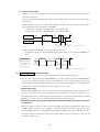
(3) Dauble twin type
Models FDCP808HES3,1008HES3
Branch
pipe (Brazing)
Strainer
(ø15.88)
Strainer
Cooling cycle
Heating cycle
Flare connecting
Indoor unit
Indoor unit
(ø15.88)
Secondary
branch pipe
(ø15.88)
Thermistor
(ThI-A)
Service valve
(Brazing)
First branch pipe
(ø19.05)
High pressure switch(63H2)
(For fan motor control)
Gsa line
808 : ø25.4
(1008
: ø28.58 )
Branch pipe
(Brazing)
High pressure
switch(63H1)
(For protection)
4way valve
Heat
exchanger
Muffler
Compressor
Solenoid
Vaive (SV)
Secondary
branch pipe
(ø9.52)
Capillary tube
Accumlator
Thermistor (ThO-R)
Branch Liquid line
pipe
808 : ø12.7
(Brazing) 1008 : ø15.88
(
: ø6.35
(208
258 : ø9.52 )
Capillary tube
)
Check valve
Service valve
(Flare connecting)
Strainer
Indoor unit
Upper
Muffler
Thermistor
(ThI-R)
Strainer
Lower
First branch
pipe
(ø19.05)
Heat
exchanger
: ø6.35
(208
258 : ø9.52 )
Thermistor
(ThO-A)
Capillary tube
Branch
pipe
(Brazing)
Flare connecting
Indoor unit
Branch
pipe (Brazing)
Strainer
(ø15.88)
Strainer
(ø15.88)
Thermistor
(ThI-A)
Heat
exchanger
Thermistor
(ThI-R)
Note (1) Refer to page 73 for piping size after branching.
Capillary tube
: ø6.35
(208
258 : ø9.52 )
Strainer
: ø6.35
(208
258 : ø9.52 )
Strainer
Branch
pipe
(Brazing)
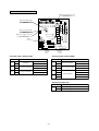
Preset point of the protective devices
Parts name
Thermistor
(for protection overloading in heating)
Mark
Equipped
unit
FDCP808HES3, 1008HES3
OFF 68˚C
ON 61˚C
ThI-R
Indoor unit
OFF 2.5˚C
ON 10˚C
Thermistor
(for frost prevention)
Thermistor
(for detecting heat
exchange temp.)
Tho-R
High pressure switch
(for controlling FM0)
63H2
High pressure switch
(for protection)
63H1
OFF 70˚C
ON 60˚C
Outdoor unit
OFF 2.79MPa
ON 2.26MPa
OFF 3.24MPa
ON 2.65MPa
Outdoor unit
- 29 -
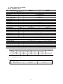
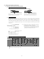
2.6 Selection chart
Correct the cooling and heating capacity in accordance with the conditions as follows. The net cooling and heating capacity can be
obtained in the following way.
Net capacity = Capacity shown on specifications × Correction factors as follows.
temperature (˚CD.B.)
Heating operation
Indoor air D.B.
Cooling operation
Outdoor air D.B.
temperature (˚CD.B.)
Coefficient of cooling and heating capacity
in relation to temperatures
(1) Coefficient of cooling and heating capacity in relation to temperatures
Indoor air W.B. temperature (˚CW.B.) ISO-T1 Standard condition
Outdoor air W.B. temperature (˚CW.B.) ISO-T1 Standard condition
Table of bypass factor
FDT series
Model
208
258
308
408
508
Hi
0.112
0.050
0.065
0.076
0.025
Lo
0.073
0.030
0.030
0.050
0.013
208
258
308
408
508
Hi
0.035
0.032
0.039
0.085
0.035
Lo
0.021
0.020
0.023
0.060
0.023
208
258
308
408
508
Item
Air flow
FDR series
Model
Item
Air flow
FDUR series
Model
Item
Air flow
Hi
0.111
0.053
0.069
0.106
0.050
Lo
0.083
0.037
0.049
0.079
0.034
- 30 -
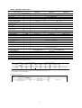
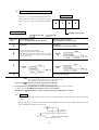
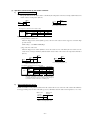
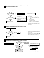
(2) Correction of cooling and heating capacity in relation to air flow rate control (fan speed)
Coefficient: 1.00 at High, 0.95 at Low
(3) Correction of cooling and heating capacity in relation to one way length of refrigerant piping
It is necessary to correct the cooling and heating capacity in relation to the one way equivalent piping length between the indoor
and outdoor units.
Equivalent piping length(1) m
7.5
10
15
20
25
30
35
40
45
50
55
Heating
1.0
1.0
1.0
1.0
1.0
0.998
0.998
0.993
0.993
0.988
0.988
1.0
0.995
0.985
0.975
0.965
0.955
0.945
0.935
0.925
0.915
0.905
Cooling
FDC808, 1008
Note (1) Equivalent piping length can be obtained by calculating as follows.
808 [φ25.4 (1 ″)]
: Equivalent piping length = Real piping length + (0.40 × Number of bends in piping)
1008 [φ28.58 (1 1/8″)] : Equivalent piping length = Real piping length + (0.45 × Number of bends in piping)
[Equivalent piping length < Limitation length of piping + 5m]
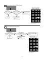
(4) When the outdoor unit is located at a lower height than the indoor unit in cooling operation and when the outdoor unit is located
at a higher height than the indoor unit in heating operation, the following values should be subtracted from the values in the
above table.
Height difference between the indoor unit and
outdoor unit in the vertical height difference
5m
10m
15m
20m
25m
30m
Adjustment coefficient
0.01
0.02
0.03
0.04
0.05
0.06
Piping length limitations
Model
All models
Item
Max. one way piping length
50m
Outdoor unit is higher 30m
Max. vertical height difference
Outdoor unit is lower 15m
Note (1) Values in the table indicate the one way piping length between the indoor and outdoor units.
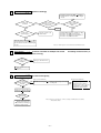
How to obtain the cooling and heating capacity
Example : The net cooling capacity of the model FDCP808HES3 with the air flow “High”, the piping length of 40m, the outdoor unit
located 5m lower than the indoor unit, indoor wet-bulb temperature at 19.0 ˚C and outdoor dry-bulb temperature 35 ˚C is
Net cooling capacity = 20000 ×
1.00 ×
(0.935 - 0.01) ×
1.0
=
18500 w
FDCP808HES3
Air flow
“High”
Length 40 m.
Height difference 5 m
- 31 -
Factor by air
temperatures
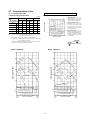
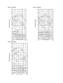
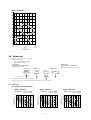
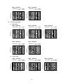
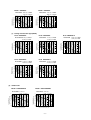
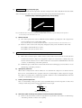
2.7 Characteristics of fan
How to interpret the blower characteristics table
(1) Cassetteria type (FDR)
• External static pressure table
40
FDR208-A
14
—
—
50
85
50
90
FDR258-A
18
30
65
45
80
50
85
FDR308-A
20
25
60
45
80
50
85
FDR408-A
28
40
70
50
80
50
85
FDR508-A
34
40
70
50
80
55
85
Static pressure (Pa)
Stan- High Stan- High Stan- High
dard speed(4) dard speed(4) dard speed(4)
20
0
igh
Air flow
(m3/min)
Square duct(3)
rd •
nda
Staow
L
Type
Standard(2)
Example : Case of FDR308-A
•H
Duct specs. 1 spot closing(1)
Unit: Pa
2 Square duct blowout...........
Internal resistance decreases
more than the standard round
duct (ø200 3-spot). 3 Pa at 17 m3/
nin. (External static pressure
increases in reverse.).
2-spots blower
internal resistance
Square duct blower internal resistance
Internal resistance without suction panel
Internal resistance without filter
Notes (1) 1 spot closing: Round duct flange at center is removed and shield
with a decorative panel (option).
(2) Standard: ø200 ducts are installed at all blowout holes.
(3) Square duct: All round ducts are removed and replaced with special
square duct flanges (option).
(4) When operating at a high speed, invert the connection of white
and red connectors on the flank of control box.
14
17
20
Air flow (m3/min)
Model FDR208-A
Model FDR258-A
120
120
•
eed
h sp it
Hig er lim
Upp
100
100
r
we
ard
Lo
w
w
igh
•
•H
rd
h
Lo
20
Lo
d
an
d•
ee
sp
it
lim
St
da
H ig
rd •
gh
Hi
an
Static pressure (Pa)
gh
Hi
40
St
rd •
nda
Static pressure (Pa)
d•
•
rd it
da lim
n
a
r
St ppe
U
d•
nda
Sta
20
60
ee
sp
gh
H i ow
L
Sta
•
ed
spe imit
h
l
g
Hi wer
Lo
ee
gh
Hi
gh
Hi
ed
spe
sp
d•
rd • it
nda
Sta per lim
Up
40
p
•U
ee
80
it
lim
gh
sp
r
pe
Hi
gh
Hi
60
•
ed
spe
gh
Hi ow
L
80
3 Decorative panel...................
When the decorative panel is not
used with the ceiling return type,
the part of internal resistance
related to the panel decrease. 3 Pa
22
at 17mm3/min.
[Standard]3-spot blower
internal resistance
–20
1 2-spot blowout.....................
Internal resistance increases more
than the standard 3-spot blowout.
Approx. 14 Pa at 17m3/min.
2-spot blower internal resistance
0
[Standard]
0
[Standard]
2-spot blower internal resistance
Square duct blower internal resistance
–20
10
Lower
limit
Square duct blower internal resistance
–20
Internal resistance without suction panel
Internal resistance without filter
12
3-spot blower internal resistance
14
Air flow (m3/min)
Internal resistance without suction panel
Internal resistance without filter
15.5
Upper
limit
13
14
Lower
limit
- 32 -
16
18
Air flow (m3/min)
20
Upper
limit
Model FDR308-A
Model FDR408-A
120
120
100
100
80
ed
80
e
sp
gh
Hi igh
H
•
ed
spe imit
h
l
g
Hi pper
U
Static pressure (Pa)
rd • it
ndar lim
a
t
H
S ppe
Lo igh
U
w sp
•
•
ow
Square duct blower
internal resistance
Square duct blower internal resistance
–20
Internal resistance without suction panel
Internal resistance without suction panel
Internal resistance without filter
Internal resistance without filter
17
20
21 22
Lower
limit
22
Upper
limit
Air flow (m /min)
3
Model FDR508-A
120
100
ed
•
60
sp
gh
H i ow
L
•
rd it
da r lim
n
a
St ppe
U
ee
nd
40
•
ed
spelimit
h
g
Hi ower
L
ard
nd
Sta igh
H
d•
Sta
•
ard
•L
ow
Static pressure (Pa)
•
ed
pe mit
s
gh li
Hi pper
U
e
sp
gh
Hi igh
H
80
20
3-spot blower
internal resistance
0
4-spot blower internal resistance [Standard]
–20
Square duct blower internal resistance
Internal resistance without suction panel
Internal resistance without filter
24
26
Lower
limit
•
ed
spelimit
h
g
Hi ower
L
[Standard] 4-spot blower internal resistance
[Standard]
3-spot blower internal resistance
14
Lower
limit
•
3-spot blower internal resistance
0
0
–20
•
ed
•L
2-spot blower
internal resistance
d
H
Hi igh
gh sp
e
40
20
20
ee
it
rd
da
an
St
rd
da
an
St igh
H
d•
40
60
h
•U
lim
•
rd
da
an
St igh
H
e
pe
•
ed
pe imit
s
gh r l
Hi owe
L
ard
nd
Staow
L
Static pressure (Pa)
•
s
gh
Hi ow
L
•
rd it
da r lim
n
ta e
60 S pp
U
Hig
ed
spe
r
ppe
30
34
Air flow (m3/min)
38
Upper
limit
- 33 -
25
28
Air flow (m3/min)
31
Upper
limit
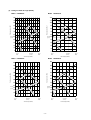
(2) Ceiling mounted duct type (FDUR)
Model
FDUR208-A
Model
120
120
110
110
100
100
80
60
Standard
pressure 50
70
60
13 12 14
30
20
10
15
17
16
Lower
limit
18
Standard
air flow
0
19
17
18
19
Model
200
180
180
160
160
80
Hi
gh
sp
ee
dHi
gh
imit
er l
-Low
d
e
e
h sp
Hig
23
Upper
limit
FDUR408-A
60
50
40
it
er lim
-Upp
dard
n
a
t
S
29
ee
- 34 -
d-
Hi
gh
it
r lim
owe
L
eed
h sp
Hig
31
33 34 35
37
Standard
air flow
Air flow(m3/min)
Air flow(m3/min)
sp
igh
27
Lower
limit
Upper
limit
gh
-H
0
Hi
ard
nd
Sta
Standard
air flow
80
er
-Low
dard
Stan
ow
rd-L
nda
Lower
limit
100
20
20 21 22 23 24 25 26 27 28 29 30
it
lim
per
p
d-U
pee
hs
g
i
H
120
Standard
pressure
igh
-H
ard
nd
Sta
t
limi
pper
d-U
r
a
d
Stan
Sta
0
22
Standard
air flow
w
Lo
dee
sp
gh
Hi
100
Static pressure (Pa)
gh
Hi
it
lim
er
p
Up
edspe
w
Lo
dee
sp
gh
Hi
Static pressure (Pa)
120
20
gh
140
140
60
50
40
Hi
er
Low
eedh sp
g
i
H
t
limi
Air flow(m3/min)
FDUR308-A
200
Standard
pressure
d-
21
20
Lower
limit
Upper
limit
Air flow(m3/min)
Model
ee
mit
er li
Upp
d
r
da
Stan
40
sp
er
ow
-L
rd
da
an
St
10
gh
Standard
pressure 50
er
ow
rd-L
nda
Sta
20
Hi
igh
-H
ard
nd
Sta
30
80
igh
rd-H
nda
Sta
it
r lim
ppe
U
rd
nda
Sta
40
0
er
-Low
peed
s
h
Hig
t
limi
r
ppe
d-U
e
e
p
hs
Hig it
lim
w
Lo
dee
sp
gh
Hi
w
-Lo
eed
h sp
Hig
70
90
Static pressure (Pa)
per
-Up
eed
p
s
h
Hig it
lim
gh
Hi
dee
sp
gh
Hi
Static pressure (Pa)
90
FDUR258-A
39
41
Upper
limit
Model
FDUR508-A
200
180
160
120
gh
Hi
100
80
Standard
pressure
it
lim
er
pp
U
ed
spe
Hi
gh
sp
ee
dHi
gh
w
Lo
dee
sp
gh
Hi
Static pressure (Pa)
140
limit
pper
rd-U
a
d
n
Sta
ow
rd-L
nda
Sta
gh
Hi
dee
sp
gh
Hi
60
50
40
limit
ower
ed-L
e
p
s
High
20
0
33.5 35.5 37.5 39.5 41.5 43.5 45.5 47.5 49.5
Lower
50
42
limit
Upper
Standard
air flow
limit
Air flow(m3/min)
2.8 Noise level
Notes (1) The data are based on the following conditions.
Ambient air temperature:
Indoor unit 27˚C DB, 19˚C WB.
Outdoor unit 35˚C DB.
Indoor unit
Measured based on JIS B 8616
Mike position as below
Outdoor unit
Measured based on JIS B 8616
Mike position: front height is 1 meter.
FDR series
FDUR series
Silent panel
Canvas panel
Unit
Unit
Unit
1.5m
FDT series
1.5m
1.5 m
Mike (center & low points)
(2) The data in the chart are measured in an unechonic room.
(3) The noise levels measured in the field are usually higher than the data because of reflection.
(1) Indoor unit
Ceiling recessed type (FDT)
Model FDT208-A
Model FDT308-A
Model FDT258-A
Noise level 38 dB (A) at HIGH
33 dB (A) at LOW
70
70
70
50
N50
40
N40
30
30
N30
N2
0
20
63
125
250
500
1000
2000
Mid octave band frequency (Hz)
4000
20
8000
Sound pressure level
(Standard 0.0002µ bar) dB
Sound pressure level
(Standard 0.0002µ bar) dB
60
40
70
N70
N70
N60
50
70
70
N70
60
Noise level 41 dB (A) at HIGH
35 dB (A) at LOW
Noise level 39 dB (A) at HIGH
35 dB (A) at LOW
60
60
N60
50
50
N50
40
40
N40
30
30
N30
N2
0
20
63
125
250
500
1000
2000
Mid octave band frequency (Hz)
- 35 -
4000
20
8000
Sound pressure level
(Standard 0.0002µ bar) dB
(a)
60
60
N60
50
50
N50
40
40
N40
30
30
N30
N2
0
20
63
125
250
500
1000
2000
Mid octave band frequency (Hz)
4000
20
8000
Model FDT508-A
Model FDT408-A
Noise level 49 dB (A) at HIGH
43 dB (A) at LOW
Noise level 48 dB (A) at HIGH
40 dB (A) at LOW
70
70
70
70
N70
60
60
N60
50
50
N50
40
40
N40
30
30
N30
N2
0
20
63
125
250
500
1000
2000
Sound pressure level
(Standard 0.0002µ bar) dB
Sound pressure level
(Standard 0.0002µ bar) dB
N70
20
8000
4000
60
60
N60
50
50
N50
40
40
N40
30
30
63
125
Mid octave band frequency (Hz)
250
500
1000
2000
20
8000
4000
Mid octave band frequency (Hz)
Cassetteria type (FDR)
Silent panel
Model FDR208-A
Model FDR258-A
Noise level 43 dB (A) at HIGH
37 dB (A) at LOW
70
Model FDR308-A
Noise level 43 dB (A) at HIGH
37 dB (A) at LOW
70
70
60
N60
50
50
N50
40
40
N40
30
30
N30
N2
0
20
63
125
250
500
1000
2000
60
60
50
50
N50
40
40
N40
30
30
N30
N2
0
63
125
Mid octave band frequency (Hz)
250
500
1000
2000
Noise level 45 dB (A) at HIGH
38 dB (A) at LOW
60
N60
50
50
N50
40
40
N40
30
30
N30
20
1000
2000
30
30
N30
N2
0
63
125
250
500
1000
2000
4000
20
8000
70
4000
60
60
N60
50
50
N50
40
40
N40
30
30
N30
N2
0
20
20
8000
63
125
Mid octave band frequency (Hz)
250
500
1000
2000
4000
20
8000
Mid octave band frequency (Hz)
Canvas panel
Model FDR208-A
Noise level
Model FDR258-A
Noise level 44 dB (A) at HIGH
38 dB (A) at LOW
44 dB (A) at HIGH
38 dB (A) at LOW
70
70
70
50
N50
40
N40
30
30
N30
N2
0
20
63
125
250
500
1000
2000
Mid octave band frequency (Hz)
4000
20
8000
Sound pressure level
(Standard 0.0002µ bar) dB
60
40
70
N70
N60
50
Noise level 45 dB (A) at HIGH
39 dB (A) at LOW
70
70
N70
60
Model FDR308-A
60
N70
60
N60
50
50
N50
40
40
N40
30
30
N30
N2
0
20
63
125
250
500
1000
2000
Mid octave band frequency (Hz)
- 36 -
4000
20
8000
Sound pressure level
(Standard 0.0002µ bar) dB
2)
40
N40
N70
Sound pressure level
(Standard 0.0002µ bar) dB
Sound pressure level
(Standard 0.0002µ bar) dB
60
500
40
Noise level 46 dB (A) at HIGH
39 dB (A) at LOW
N70
250
50
N50
Mid octave band frequency (Hz)
70
70
125
50
Model FDR508-A
70
63
60
N60
20
20
8000
4000
60
Mid octave band frequency (Hz)
Model FDR408-A
N2
0
N70
N60
20
20
8000
4000
70
N70
Sound pressure level
(Standard 0.0002µ bar) dB
Sound pressure level
(Standard 0.0002µ bar) dB
N70
60
Noise level 44 dB (A) at HIGH
38 dB (A) at LOW
70
70
Sound pressure level
(Standard 0.0002µ bar) dB
1)
Sound pressure level
(Standard 0.0002µ bar) dB
(b)
N30
N2
0
20
60
60
N60
50
50
N50
40
40
N40
30
30
N30
N2
0
20
63
125
250
500
1000
2000
Mid octave band frequency (Hz)
4000
20
8000
Model FDR408-A
Model FDR508-A
Noise level 46 dB (A) at HIGH
39 dB (A) at LOW
70
Noise level 47 dB (A) at HIGH
40 dB (A) at LOW
70
70
70
N70
60
60
Sound pressure level
(Standard 0.0002µ bar) dB
N60
50
50
N50
40
40
N40
30
30
N2
N30
0
20
63
125
250
500
1000
2000
60
N60
50
50
N50
40
40
N40
30
30
N2
63
125
Mid octave band frequency (Hz)
(c)
N30
0
20
20
8000
4000
60
250
500
1000
2000
4000
Ceiling mounted duct type (FDUR)
Model FDUR208-A
Model FDUR308-A
Model FDUR258-A
Noise level 40 dB (A) at HIGH
36 dB (A) at LOW
70
70
70
Souud Pressure Level
(standard 0.0002µ bar)
Souud Pressure Level
(standard 0.0002µ bar)
60
N60
50
50
N50
40
40
N40
30
30
20
63
125
250
60
500
1000
2000
4000
60
50
50
N50
40
40
N40
30
30
N2
20
8000
63
125
250
500
1000
2000
4000
70
70
N70
60
Souud Pressure Level
(standard 0.0002µ bar)
Souud Pressure Level
(standard 0.0002µ bar)
N70
60
N60
50
50
N50
40
40
N40
30
30
20
125
250
500
1000
60
60
N60
50
50
N50
40
40
N40
30
30
N30
0
2000
4000
N2
20
8000
N30
0
20
63
125
Mid Octave Band Frequency (Hz)
250
500
1000
2000
4000
Mid Octave Band Frequency (Hz)
(2) Outdoor unit
Model FDCP1008HES3
Model FDCP808HES3
Noise level 58 dB (A)
COOL
70
Noise level 58 dB (A)
HEAT
COOL
70
70
HEAT
60
N60
50
50
N50
40
40
N40
30
30
N2
N30
0
20
125
250
500
1000
2000
Mid octave band frequency (Hz)
4000
70
N70
20
8000
Sound pressure level
(Standard 0.0002µ bar) dB
Sound pressure level
(Standard 0.0002µ bar) dB
N70
60
60
60
N60
50
50
N50
40
40
N40
30
30
N2
N30
0
20
63
125
250
500
1000
2000
Mid octave band frequency (Hz)
- 37 -
50
50
N50
40
40
N40
30
30
4000
20
8000
N30
0
20
63
125
250
500
1000
2000
4000
Mid Octave Band Frequency (Hz)
Noise level 45 dB (A) at HIGH
41 dB (A) at LOW
70
70
63
20
8000
Model FDUR508-A
Noise level 44 dB (A) at HIGH
40 dB (A) at LOW
60
N60
N2
Mid Octave Band Frequency (Hz)
Model FDUR408-A
60
N30
0
20
Mid Octave Band Frequency (Hz)
N2
70
N70
N60
N30
0
70
70
N70
60
N2
Noise level 41 dB (A) at HIGH
37 dB (A) at LOW
Noise level 41 dB (A) at HIGH
37 dB (A) at LOW
N70
63
20
8000
Mid octave band frequency (Hz)
Souud Pressure Level
(standard 0.0002µ bar)
Sound pressure level
(Standard 0.0002µ bar) dB
N70
20
8000
20
8000
3
ELECTRICAL DATA
3.1 Electrical wiring
(1) Indoor unit
Ceiling recessed type (FDT)
Models All models
4
6
7
CnJ
H UH
OR
FMI
L
LM
WH
WH
ThI–R
CnT
BK
BK
CnS2
CnI
CnR
WH
WH
Y / GN
CnF1
CnJ
ThI–A
CnN
FS
ON
WH
Y / GN
WH
WH
RD
RD
SW1
DM
CFI
(49FI)
CnH2
BK BK
BK
BK
Test
CnI
CnR
BK
BL
RD
OR
CnF1
XR5
CnQ
13
CnH
8
Option
XR3
XR4
CnN
3
BK
CnW1
X2
XR1
XR2
CnS
PC
220/240V
14
X7
PC
BR
X3
GR
10
RD
BL
12V
BR CnW2
RD
9
X1 X4 X7
X2 X5
X3 X6
X4
X1
SW2
1 2 3 4
OFF
ON
WH
BK
X6
X5
BR
5
2
BR
4
WH
Val
BK
3
Tr I
BK RD
1
BL
{
2
RD
RD
to outdoor unit
{
TB
1
OR
Power wires
to outdoor unit
SW3
BK
BK LS
BK
BK
RD
WH
BK
CnB
(a)
1 2 3 4
X
Y
Z
OFF
5
X
Y
Z
RD WH BK
Printed circuit board
Meaning of marks
Mark
FMI
49FI
CFI
LM
LS
DM
FS
Thc
Remote
controller
Color mark
Parts name
Fan motor (indoor unit)
Internal thermostat for FMI
Capacitor for FMI
Louver motor
Limit switch
Drain motor
Float switch
Mark
X1~7
Thc
ThI-A
ThI-R
TrI
VaI
PC
Parts name
Auxiliary relay
Thermistor
Thermistor
Thermistor
Transformer
Varistor
Photo coupler
Mark
CnA-W
TB
■
v
SW1
SW2, 3
Parts name
Connector
Terminal block
Connector
Terminal (F)
Switch (Address set)
Changeover switch
Mark
BK
BL
BR
GR
OR
RD
Color
Black
Blue
Brown
Gray
Orange
Red
(b) Cassetteria type (FDR)
Models All models
CFI2
WH
CnF2
CnS
CnT
CnH
RD RD
CnH2
BK BK
BK
BK
CnN
PC
220/240V
XR5
CnQ
RD
RD
Test
GR
BR
/WH
BK
BK
CnI
CFI1
ThI–R
BK
BK
FS
CnR
CnRI
CnF3
WH
ThI–A
CnN
SW1
DM
OR
CnF4
CnF4
CnRI
CnR
Option
XR3
RD
FMI1 OR
(49FI)
CnRI
XR1
XR2
XR4
CnI
ON
CnRI
OFF
ON
SW2
1 2 3 4
SW3
CnB
Y / GN
M H UH
CnF4
13
BR
OR
CnF5
CnF2
L
4
WH
Y / GN
CnF5
3
6
BK/WH
12V
BR CnW2
BK
CnW1
X2
BK
FMI2 OR
(49FI)
BL/WH
X1
BR
M H UH
CnF5
RD/WH
X1 X4 X7
X2 X5
X3 X6
WH
L
CnF3
7
BK BK
8
BR
PC
BK
14
X7
BL
BR
X3
RD
10
RD
BL
X4
BR
9
Val
X6
BR
5
BK
X5
BL
4
11
BL
3
WH
Tr I
BK RD
BK
{
2
1
Y / GN
to outdoor unit
{
RD
RD
Power wires
to outdoor unit
TB
1
1 2 3 4
RD
WH
BK
TB
X
Y
Z
OFF
5
X
Y
Z
RD WH BK
Printed circuit board
Note(1) "FMI2" and the following wires (shown in
) are equipped only for FDR408, 508.
Meaning of marks
Mark
FMI1, 2
49FI
CFI1, 2
DM
FS
X1~7
Parts name
Fan motor (indoor unit)
Internal thermostat for FMI
Capacitor for FMI
Drain motor
Float switch
Auxiliary relay
Thc
Remote
controller
Color mark
Mark
Thc
ThI-A
ThI-R
TrI
VaI
PC
Parts name
Thermistor
Thermistor
Thermistor
Transformer
Varistor
Photo coupler
Mark
CnA-W
TB
■
v
SW1
SW2,3
- 38 -
Parts name
Connector
Terminal block
Connector
Terminal (F)
Switch (Address set)
Changeover switch
Mark
BK
BL
BR
GR
OR
RD
Color
Black
Blue
Brown
Gray
Orange
Red
Mark
WH
Y/GN
RD/WH
BL/WH
BK/WH
BR/WH
Color
White
Yellow/Green
Red/White
Blue/White
Black/White
Brown/White
(c)
Ceiling mounted duct type (FDUR)
Models All models
L
CnT
220/240V
PC
Option
XR3
XR4
CnN CnH
CnH2
BK BK
BK
BK
ThI–A
ThI–R
BK
BK
RD
RD
CnN
SW1
FS
CFI
CnF2
CnF1
CnR
ON
SW2
1 2 3 4
CnI
OFF
ON
SW3
1 2 3 4
WH
WH
Y / GN
Y / GN
CnF1
CnI
DM
WH
Y / GN
Y / GN
H UH
FMI
XR1
XR2
XR5
CnQ
Test
13
CnR
CnF1
(49FI)
CnF2
4
CnS
BL BL BL/WH
RD RD
BK
BL
CnF2
6
7
OFF
CnB
8
GR
3
GR
PC
GR
14
12V
BR CnW2
BK
CnW1
X2
GR
BR
X3
BR/WH
10
Y
BL
Y
5
9
X1 X4 X7
X2 X5
X7
X3 X6
X4
X1
BR/WH
4
BK
Val
X6
X5
BK/WH
}
3
2
BK
to outdoor unit
WH
2
TrI
BK RD
1
WH
}
TB
RD
1
RD/WH
Power wires
to outdoor unit
5
CnS2
BK
BK
BK
BK
LS
TB
RD
WH
BK
X
Y
Z
Printed circuit board
X
Y
Z
RD WH BK
Thc
Remote
controller
Meaning of marks
Mark
Color mark
Parts name
Fan motor (indoor unit)
Internal thermostat for FMI
Capacitor for FMI
Drain motor
Float switch
Auxiliary relay
Thermistor
Thermistor
Thermistor
FM
49FI
CF
DM
FS
X1~7
Thc
ThI-A
ThI-R
Mark
Parts name
Transformer
Varistor
Photo coupler
Connector
Terminal block
Connector
Terminal (F)
Switch (Address set)
Changeover switch
Trl
Val
PC
CnA ~ W
TB
■
v
SW1
SW2, 3
Mark
BK
BL
BR
GR
OR
RD
Color
Black
Blue
Brown
Gray
Orange
Red
Mark
WH
Y/GN
RD/WH
BL/WH
BK/WH
BR/WH
Color
White
Yellow/Green
Red/White
Blue/White
Black/White
Brown/White
(2) Outdoor unit
Models FDCP808HES3, 1008HES3
Power source
3Phase 380-415V 50Hz
TB
L1 RD
F(5A)
RD/WH
L2 WH
5
2
4
6
X05
X04
21
22
5
27
X01
8
9
CnE
Parts name
Compressor motor
Fan motor (outdoor unit)
Magnetic contactor for CM
Internal thermostat for CM
Intrnal themostat for FMo
Crankcase heater
Capacitor for FMo
Auxiliary relay
High pressure switch (for protection)
High pressure switch (for control)
Fuse
Indication lamp (Green)
7
(Checker)
X07
Y/GN
to indoor unit
CnL
LED-G
(Test)
(Normal)
LED-R
Vao
Meaning of marks
6
CnQ
CnA1 CnA2
X02
}
Power wires
to indoor unit
BK
26
Printed Circuit Board
CM
FMo1,2
52C
49C
49Fo1,2
CH
CFo1,2
Xo
63H1
63H2
F
LED-G
4
BK
23 25
OR
20
OR
19
BR
P
18
14V
220/240V
X03
P
17
BR
CH
BL
16
BR
BL
14 15
BR
GR
GR
WH
OR
Y
BK
OR/WH
OR/WH
CnM2
WH
OR
Y
12 13
X07
Mark
3
BL/WH
}
63H2
63H1
PC
X05
BK/RD
Tho-R Tho-A
A2
PC
X04
X03
F(3.15A)
X02
BK
RD
RD
3 28
1 2
X01
CnM1
BK/WH
CT2
WH
CM W
49C
52C
A1
BL/WH
20S
CF02
H
BK/RD
(49FO2)
CF01
BR/WH
FMO2
(49FO1)
H L
CnR
WH
FMO1
CT1
2/N
SV
BR/WH
V
U
TB
1
BL
52C
BK
BL
3
23Td
F(3.15A)
RD
WH
1
RD
Y/GN
N BK/WH
BL
BK
L3 BL
BL
BK/WH
(Check)
Tro
Meaning of marks
Mark
LED-R
CT1,2
Tho-R
Tho-A
Tro
Vao
PC
CnA~R
TB
SV
23Td
Parts name
Indication lamp (Red)
Current sensor
Thermistor (outdoor H.Ex.temp.)
Thermistor (outdoor air temp.)
Transformer
Varistor
Photo coupler
Connector
Terminal block
Solenoid valve (for control)
Thermostat
- 39 -
Color mark
Mark
BK
BL
BR
GR
OR
P
RD
WH
Color
Black
Blue
Brown
Gray
Orange
Pink
Red
White
Mark
BK/RD
BK/WH
BL/WH
BR/WH
OR/WH
RD/WH
Y/GN
Y
Color
Black/Red
Black/White
Blue/White
Brown/White
Orange/White
Red/White
Yellow/Green
Yellow
4
OUTLINE OF OPERATION CONTROL BY MICROCOMPUTER
(1) Wired remote controller
Models FDT, FDR, FDUR series
FDR and FDUR series are not provided with AUTO SWING switch.
Panel shown below will appear if you open the cover. All contents of display on the LCD are indicated simultaneously for the purpose
of explanation.
Pull the knob on the cover to this side to open it downward.
Filter sign
Operation mode display
When this sign is indicated, clean the filter.
Remote display
Displays the operation mode that has
been selected.
(Cooling only air-conditioner has the display
of "COOL" ,"DRY" and "FAN" only.)
This is displayed when the unit is controlled
with an individual controller during normal operation.
(Also displayed when the air conditioner is stopped.)
Heating
preparation display
Central display
Operation/
Inspection indicator lamp
This is displayed when the unit is
controlled with the optional central console.
During operation: Green lamp flashes.
In case of error: Red lamp flashes.
On/Off switch
Timer operation display
Contents of timer operation are displayed.
(Also displayed when the air conditioner
is stopped.)
CENTER REMOTE FILTER
PROGRAM TIMER
ON
Setting
temperature display
OFF
A M
P M
AUTODRYCOOLFAN HEAT
SET TEMP
E
°C
FAN
Hi
Mi
Lo
Outdoor No.
°C
Return air
temperature display
Displays the temperature
that has been set.
FILTER
RESET
TIMER
CHECK
SET
TEMP
TIME
Fan speed display
Displays the fan speed that has been set.
HOT
KEEP
Use this switch to start or stop the
air conditioner.First push on the
switch starts the unit and second
push stops it. (The switch can be
operated without opening the cover.)
F A N
SPEED
AUTO
Filter reset switch
Displays the return air temperature.
MODE
Note
Indicated value may be different
from actual reading on a thermometer
or other instrument but this is not
necessarily an error.
Auto swing display
Use this switch to reset (erase) the filter
sign display.
(Press the switch after cleaning the air filter.)
Indicates the swing louver condition.
Mode switch
Cover
Use this switch to select operation
modes.
Inspection switch
Fan speed switch
Use this switch when servicing the unit.
Use this switch to set a fan speed.
Timer switch
Auto swing switch
Use this switch when selecting contents of timer operation.
Use this switch to operate or stop
the swing louver.
Set switch
Temperature/
Time setting switch
Use this switch to set a time for the timer.
Use this switch to set the room
temperature or time on the timer.
- 40 -
(2) Outline of microcomputer control function
(a)
Operation control function by the indoor controller
1)
Room temperature control (Differential of thermostat)
Heating operation
Cooling operation
ON (52C)
OFF (52C)
+1
Set temp.by thermostat
-1
2)
OFF (52C)
-1
+1
Set temp.by thermostat
Temperature difference between thermostat set temp.
Temperature difference between thermostat set
and return air temp. (Detected by Th I-A)
temp. and return air temp. (Detected by Th I-A)
Automatic operation
If the Auto mode is selected on the remote control device, the selection of cooling or heating can be made automatically
depending on the room temperature (and the temperature of indoor heat exchanger). (When the switching between the
cooling and the heating is made within 3 minutes, the compressor will not operate for 3 minutes.) This will make much
easier the switching of cooling/heating at the change of season and can be adapted to the unmanned operation at bank
cash dispenser.
Notes (1) During the automatic switching of cooling/heating the room temperature
is controlled based on the setting of room temperature.
(2) If the temperature of indoor heat exchanger rises beyond 63˚C during
the heating operation, it is switched automatically to the cooling
operation. For an hour after this switching, the heating operation is suspended regardless of the temperature as shown at left.
Cooling operation
Heating operation
Setting room temp.
Room temp. (detected at Th I-A) [deg]
Suspended heating operation
Ready for
heating
Indoor heat exchanger temperature (˚C)
3)
Control parts operation during cooling and heating
Function
Control part
Compressor
4-way valve
Outdoor fan
Cooling
Thermostat Thermostat
ON
OFF
×
×
Fan
–
Thermostat
ON
×
Heating
Thermostat
Defrost
OFF
×
×
×
×
×
×
×
×
×
/×
Louver motor
Note (1)
×
×
/×
Indoor fan
Condensate motor
×
Dry
Thermostat Thermostat
HOT START
ON
OFF
×
× (2min. ON) × (2min. ON)
× (2min. ON)
:ON
× :OFF
/ × :According to control other than temperature control.
- 41 -
× (2min. ON)
4)
Dehumidifying operation (“THERMAL DRY”)
The compressor, the indoor fan motor and the outdoor
Operation block
fan motor are operated intermittently under thermistor
(ThI-A) control according to the appropriate operation
block, to provide cooling operation for the dehumidi-
D
fying.
C
B
-2
Low
A
+3
High
Pattern of operation
Set temp. by thermostat
CM, FMO: ON
Operation
block
FMI : ON
Thermal drying starting
(for 8 or 16 minutes after operation started)
Normal thermal dry operation
(after completion of thermal drying)
(16 minutes)
(8 minutes)
Continuous cooling operation (FMI:Lo)
A
• Cooling operation (Thermostat ON)
• Indoor fan operating with the setting air flow.
• When the thermostat is turned off, the indoor fan operates
for 30 seconds with the Lo operation in the wind blowing
mode and then stops.
B
(8 minutes)
CM, FM0
FMI
(8 minutes)
(8 minutes)
CM, FM0
FMI
CM, FM0
FMI
C
D
(8 minutes) All stoppage
Notes (1) Operation block A B : Normal cooling operation for 16 minutes after operation is started.
Operation stops by thermostat when the set temperature is reached.
After 16 minutes, normal thermal drying operation starts.
Operation block C D : Operation as above is performed for 8 minutes.
After 8 minutes, normal thermal drying operation starts.
(2) In normal operation, the temperature is checked at 8 minute intervals after normal thermal drying
operation is started, to determine which operation block is to the selected.
Operation block A thermal drying is carried out if the thermostat set temperature is constant.
5)
Hot spurt
In the hot spurt mode, the control is conducted at the level +2 higher than the setting temperature at the start of heating
operation.
The hot spurt is canceled either after the initial thermostat OFF, when the indoor heat exchanger temperature reaches
61˚C or 60 minutes after the start of the mode.
Room temperature (deg)
- 42 -
6)
FM control with the heating thermostat turned off (For cold draft prevention)
In order to prevent a cold draft while the heating thermostat is turned off, the indoor blower is controlled in response to
the temperature of the indoor heat exchanger as illustrated below. It should be noted that if SW3-4 on the indoor PCB
is turned off, the indoor blower will stop so far as the temperature of the indoor heat exchanger is lower than 40˚C. It
will be turned to the Lo operation 5 minutes later.
(Setting air flow)
Note (1) After the thermostat is reset, it returns to the hot start
control.
Lo
40
45
Indoor heat exchanger temperature (˚C)
7)
Hot start (Cold draft prevention during heating)
1)
If the indoor heat exchanger temperature is lower than 30˚C when the heating operation has started, the following
indoor blower control is performed.
(1)
In case of the thermostat off condition: Lo operation
(2)
In case of the thermostat on condition : Stop
(3)
If the indoor heat exchanger temperature exceeds 30˚C or 7 minutes after the beginning of hot start, the hot
start terminates and it returns to the setting airflow of the blower.
2)
If the indoor heat exchanger temperature is lower than 30˚C when the unit is heating under the thermo-ON
condition, the indoor fan operates in the Lo mode. As the temperature rises higher than 30 ˚C or 7 minutes after the
beginning of hot start, the hot start terminates and it returns to the setting air flow.
8)
Indoor fan control during defrost operation
1)
The indoor fan operation is changed from the setting airflow to the Lo operation 40 seconds before the start of
defrost operation (when the defrost thermostat is turned ON) and stops if the indoor heat exchanger temperature
drops below 20˚C.
2)
After the stop as described in 1)-above, the control will be conducted as illustrated below depending on the indoor
heat exchanger temperature.
Lo
Stop
20
30
Indoor heat exchanger temperature(˚C)
3)
If the indoor heat exchanger temperature rises beyond 30˚C of 7 minutes after the end of defrosting, the indoor fan
control related to the defrosting is completed.
9)
Condensate pump motor (DM) control
During the cooling or Dehumidifying operation, the condensate pump motor (DM) is synchronized with the start of
compressor operation. If the operation is switched from the operation stop, error stop, thermostat stop and the cooling
of defrosting operation to the fan or heating operation, the drain motor continues to operate for 2 minutes after the
switching.
Overflow detection by means of the float switch is always on regardless of the operation mode. If an overflow occurs
(or the float switch is not connected or the wire is broken), the operation is interrupted as the error stop and the drain
motor is operated until the state of float switch is normalized.
- 43 -
10)
Frost prevention during cooling
In order to prevent the frosting during cooling operation, the temperature of indoor unit heat exchanger (detected by
ThI-R) is checked 9 min, after the compressor operation start and the unit operation.
This cycle is not operated for 9 min. after the resetting of this frost prevention mechanism.
Cooling operation
OFF (52C)
2.5
10
Indoor heat exchanger temperature (˚C)
11)
Compressor inching prevention control
a)
Compressor 3 minutes delay control
The compressor will remain in stop state for three minutes. When the compressor is stopped by thermostat, ON/
OFF switch, and/or by occurrence of trouble.
b)
Compressor 3 minutes forced operation control
Compressor cannot be stopped for 3 minutes after it started. However, it will be stopped immediately when the
thermostat is turned off due to the operation stop initiated by the ON/OFF switch or the change of operation mode.
Note (1) Both the error control and the protective control take priority over this control.
12)
Overload protection during heating
If an overload condition has been detected by the indoor heat exchanger temperature and it has continued for more than
2 seconds during heating, the compressor is stopped. The compressor is started after a delay of 3 minutes and, if the
overload condition is detected again whithin 60 minutes after the initial detection, the compressor is stopped with the
error stop.
Heating operation
68
61
Indoor heat exchanger
temperature(˚C)
13)
Automatic restart control
If there is interruption of power while the unit is operating, the unit operates after power restoration under the same
condition as prior to the power interruption. However the compressor will only be able to start three minutes after the
power restoration. Furthermore, if the timer was operating prior to the power interruption, the unit remains stopped
even after the restoration of service.
Note (1) Becomes invalid if the dip switch SW3-1 on the indoor PC board is at OFF (SW3-1 is set at ON when unit is shipped from the factory).
14)
Thermistor disconnection detection control
a)
Detection of indoor return air thermistor disconnection
¡ If there is detection of a disconnection on the return air thermistor in 10 seconds after turning the power ON,
the compressor is stopped. If there is a second disconnection on the return air thermistor detected within 60
minutes, there is emergency stop.
Note (1) If the first disconnection on the return air thermistor is detected for a period of 6 continuous minutes, there is emergency stop. If there is no
detection of a second disconnection on the return air thermistor whithin 60 minutes, the first detection becomes invalid.
- 44 -
b)
Detection of heat exchanger thermistor disconnection
¡ If a disconnection is detected on the heat exchanger thermistor in 20 seconds after the compressor has been
operating for 2 minutes, the compressor is stopped. If a second disconnection on the heat exchanger thermistor line is detected within 60 minutes, there is emergency stop.
Note (1) If the first disconnection on the heat exchanger thermistor is detected for a period 6 continuous minutes, there is emergency stop.
If there is no detection of second disconnection on the heat exchanger thermistor within 60 minutes, the first detection becomes invalid.
15)
Drain detection
a)
If there is detection of a drain abnormality during cooling operation, the drain pump goes ON for 5 minutes and
the compressor which had been running comes to a stop.
Overflow detection is carried out at all times with the float switch regardless of operational mode. If an overflow
is generated (or if the float switch is not yet connected or has been disconnected). there is emergency stop (E9 is
displayed) the drain motor operates until reset of the float switch.
b)
If a drain abnormality is detected during cooling operation, there is emergency stop (E9 is displayed) to stop the
compressor, and the drain pump is operated with the drain motor until reset of the float switch.
c)
If a drain abnormality is detected during a stop state or fan operation, there is forced operation of the drain pump
for 5 minutes. After 5 minutes have elapsed, the drain motor stops if the float switch is reset. Otherwise, there is
emergency stop (E9 is displayed) and the drain motor operates until the float switch is reset.
d)
16)
If the float switch is not connected or if there is a disconnection, there is emergency stop.
Low voltage guard control
If the power source voltage remains at a value of 80% of rating or less for 3 continuous minutes during operation of the
compressor, the compressor stops (52C OFF). Furthermore, if the power source voltage remains at a figure of 15% of
rating or greater after 3 minutes have elapsed since stopping the compressor, there is restarting of the compressor (52C
ON). Moreover, during stoppage of the compressor.
Note (1) When starting the compressor for the first time after turning the operational switch ON, there is starting regardless of the power source voltage.
Furthermore, if dip switch SW 3-2 on the internal substrate is OFF, this becomes invalid. (Switch SW 3-2 is set to ON upon shipment from the
factory).
17)
Refrigerant shortage error
When 52C is ON when operating in cooling (including automatic cooling), if heat exchanger sensor temperature for the
indoor unit (ThI -R) does not drop to 25 °C or less for 40 minutes 5 minutes or more after the start of operation, an
abnormal stop due to insufficient refrigerant is performed.
18)
External control (remote display)/control of input signal
a)
External control (remote display) output
Following output connectors (CNT) are provided on the control circuit board of indoor unit.
¡ Operation output: Power to engage DC 12V relay (provided by the customer) is outputted during operation.
¡ Heating output: Power to engage DC 12V relay (provided by the customer) is outputted during the heating
operation.
¡ Compressor ON output: Power to engage DC 12V relay (provided by the customer) is outputted while the
compressor is operating.
¡ Error output: When any error occurs, the power to engage DC 12V relay (provided by the customer) is outputted.
- 45 -
b)
Control of input signal
(Make sure to connect the standard remote control unit. Control of input signal is not available without the standard remote control unit.)
Control of input signal (switch input, timer input) connectors (CNT) are provided on the control circuit board of
the indoor unit.
However, when the operation of air conditioner is under the Center Mode, the remote control by CnT is invalid.
At shipping from factory (J5 (SW5-2) on PCB OFF)
¡ Input signal to CnT OFF → ON [Edge input] ... Air conditioner ON
¡ Input signal to CnT ON → OFF [Edge input] ... Air conditioner OFF
ON
CnT input
ON
OFF
ON
OFF
OFF
ON
ON
OFF
Unit A
ON
OFF
Remote controller
operation OFF
Remote controller
operation ON
(Last operation has priority.)
When J5 (SW5-2) on the PCB of indoor unit is turned on at the field.
Input signal to CnT becomes Valid at OFF Æ ON only and the motion of air conditioner [ON/OFF] is inverted.
ON
CnT input
ON
OFF
OFF
ON
ON
Unit A
ON
OFF
OFF
ON
OFF
Remote controller
operation OFF
19)
Auto Swing Control
OFF
Remote controller
operation ON
(Last operation has priority.)
(Only FDT models)
¡ Have a louver motor to move the louvers up and down for the so called “auto swing” function.
¡ The louver auto swing starts when the AUTO SWING key is pressed once and stops when the AUTO SWING key
is pressed again. The louver position is displayed on the LCD on the remote controller. During auto swing, the
position displayed on the LCD changes, but the positions of the louvers and the display are not coordinated. (The
louvers swing 3 - 4 ti))mes per minute but the display changes once per second.)
¡ Stopping the louvers
When the AUTO SWING key is pressed to stop the louver movement, the LCD louver-position display stops and
the louvers stop when they come to the position displayed on the LCD. There are four louver stop position on the
LCD. (When jumper wire J3 on the indoor unit printed circuit board is cut, the louvers stop immediately at the AUTO
SWING key is pressed to stop them and the LCD display changes to show this position.
¡ Movement of louver when the power supply to the controller controlling 4 positions of the louver
is switched on.
When power supply is switched on, the louver will automatically swing about 2 times (without operating remote
controller). This is an action for the microcomputer to confirm the louver position in order to input the cycle of the
louver motor (LM) to the microcomputer with the limit switch (LS) pushing the louver motor (LM). If the LS action
is not input to the microcomputer, the louver will stop within 1 minute after the power supply is switched on and
will not move from then on.
- 46 -
¡ Keeping the louvers horizontal during heating
While HOT KEEP is displayed (during hot start operation or when the thermostat has turned off during heating
operation), the louvers stay in the horizontal position to prevent cold drafts, independent of the setting of the AUTO
SWING key (auto swing or stop). The louver position display of LCD displays continuously the original position
before this control operation.
When the HOT KEEP display goes out, both the louvers and the LCD display return to their previous position.
(However, after the power supply to the unit is switched on, the louvers swing two times as a check of the power
source frequency, regardless of the settings of the ON / OFF or AUTO SWING keys).
20) Using 1 remote controller to control multiple units (indoor units - up to 16 units)
a)
Function
A single remote control switch can be used for group control of multiple units (indoor units - up to 16 units). All
units in the group that have had the remote control switch set at [Operating Mode] can be turned on and off in
order of the unit number.
This functions independently of the thermostat and protection functions of each unit.
Notes (1)
The unit number is set by a switch (SW1) on the circuit board for the indoor unit.
Set SW1 : 0~9, A~F
Outdoor unit
0
1
2
3
4
Indoor/Outdoor connection wire
F
Refrigerant piping
0
1
2
3
4
F
indoor unit
Remote controller
(2)
b)
Remote controller wire
If unit number is not important, random can be used. However, setting in order from 0, 1, 2, to F will ensure setting without error.
Display to remote controller
(i)
Return air temperature, by remote or center and heating preparation: Displays for the youngest
unit for the remote mode (center mode if there is no remote mode) of the units in operation.
(ii) Inspection and filter sign: Displays either to the first corresponding unit.
c)
Confirmation of connected units
Each push of the inspection switch on the remote control displays the units connected in sequential order from the
youngest unit.
d)
Error
(i)
If an error occurs (protection device activation) with some of the units in the group, those units will have an
error stop, but the properly operating units will continue operation.
(ii) Wiring outline
Route the wire connecting each of the indoor and outdoor units as it would be for each unit. Use the terminal
block (X, Y, Z) for the remote control for the group controller and use a jumper wire among each of the
rooms.
- 47 -
(b) Operation control function by the wired remote controller
(i)
The following is the sequence of operation for the remote controller operation mode switch.
DRY
(ii)
COOL
FAN
HEAT
AUTO
CPU reset
This functions when the " inspection " and " filter reset switch " on the remote controller are pushed simultaneously. It
operates in the same manner as the power reset.
(iii) Power outage compensation function.
¡ This is enabled by setting dip switch SW3 on the remote control circuit board to ON.
¡ It records the normally used remote control modes. Once power has been restored, it restarts operation by using the
contents of the memory. Note that the stop positions for auto swing and the timer mode are cancelled.
Parts layout on the remote controller PCB
Z
X
Y
WHITE
R18
RED
IC4
IC5
BLACK
R5
R3
IC3
R4
Q3
IC1
R7
R28
Q2
TYPE
R12
R11
R13
Q1
SW1
REMOTE
THERMO
SW2
POWEP OFF
GUARAMTY
DIP switched
(SW1 ~ SW4)
SW3
TEMP DISP.
FAN SPEED
J1
SWING
DISP.
TIMER FUNC.
J2
J4
J3
Jumper wires (J1 ~ J4)
• Function of DIP switched
Switch
SW1
SW2
SW3
ON
OFF
ON
OFF
ON
OFF
• Function of Jumper wires
Function
Switch
Cooling only type
Heat pump type
J1
Remote control sensor - Enabled
Remote control sensor - Disabled
J2
Power outage compensation - ON
Power outage compensation - OFF
J3
J4
Wich
None (1)
Wich
None (1)
Wich
None (1)
Wich
None (1)
Function
Inlet temperature display - Enabled
Inlet temperature display - Disabled
Fan display - 3 speeds
Fan display - 2 speeds
Timer function - Enabled (Normal)
Timer function - Disabled
Auto swing display - ON
Auto swing display - OFF
Note (1) 'None' means that jumper wire is not provided
on the PCB or the connection ic cut.
- 48 -
(c)
Operation control function by the outdoor controller
1)
Control for outdoor unit fan
a) Cooling Operation
The speed of the fan for the outdoor unit is controlled by the temperature of the heat exchanger (Tho-R detection)
and the outdoor air temperature (Tho-A).
C Zone
A Zone
D Zone
B Zone
44
48
Heat exchanger temperature (°C)
20
25
Outdoor air temperature (°C)
Description of control for fan for outdoor unit
Fan motor
FM01(Left)
A Zone
Hi
Zone
C Zone
Hi
B Zone
D Zone
Lo
b)
FM02(Right)
Hi
OFF
OFF
Heating Operation
1 Stop control for outdoor fan
When the high pressure switch (63H2) operates, the fan for the outdoor unit is stopped to control the high
pressure switch.
63H2 settings : 2.79 OFF/2.26 ON (Mpa)
2 Tap control for outdoor fan
When the high pressure switch (63H2) is closed, the outdoor fan is controlled by the detected heat of the
outdoor heat exchanger thermistor (Tho-R) and the detected heat of the outdoor air temperature thermistor
(Tho-A).
E Zone
C Zone
A Zone
D Zone
B Zone
-3
0
Heat exchanger temperature (°C)
17
19
9
11
Outdoor air temperature (°C)
Description of control for fan for outdoor unit
FM01(Left)
Fan motor
Hi
C Zone
A Zone
Hi
D Zone
Zone
Hi
B Zone
C Zone
Hi
E Zone
Hi
D Zone
FM02(Right)
OFF
Hi
Hi
OFF
Hi
Note (1) When the fan for the outdoor unit is started when the outdoor air
temperature is more than 12 °C, it will operate at high speed for 3
seconds and then switch to low speed. After operating a low speed
for 4 minutes, it will be transferred to controlled speed.
2)
Snow protection fan control
If DIP switch SW5-2 on the printed circuit board for the outdoor unit is set to on, the fan on the outdoor unit which has
been stopped will operate for 10 seconds at Hi speed every 10 minutes when the outdoor air temperature is 3 °C or less.
Outdoor fan
operates
at Hi speed
Outdoor fan
stopped
3
5
Outdoor air temperature (°C)
- 49 -
3)
Defrost control (Only heat pump type)
Defrost operation will start when the temperature of the heat exchanger for the outdoor unit (Tho-R detection) and the
Heat exchanger temperature
outdoor air temperature (Tho-A detection) enter the start of defrost range shown in the figure below.
Initiation temp. of defrosting (Detected by Tho-R, Tho-A)
-5
-10
ing
ost
em
-15
-20
p.
of
Zone for initiate temp. of defrost
t
tia
Ini
(°C) -20
[Th0-R]
t
ion
r
def
-15
-10
-5
0
5
10
Outdoor air temperature (°C) [Th0-A]
Note (1) If DIP switch SW5-1 on the printed circuit board for the outdoor unit is set to on, defrost operation will begin when temperature of
the heat exchanger for the outdoor unit reaches -7 °C.
a)
Defrost finished
(i)
Once defrost operation has started, it will finish after the cumulative operating time of the compressor has
reached 12 minutes (factory setting: SW5-1 OFF).
Note (1) This time will become 14 minutes if the DIP switch (SW5-1) on the printed circuit board on the outdoor unit is set to on.
(ii) Patterns of defrost control can be changed by changing the setting of J18 on the PCB of outdoor unit.
● J18 (SW6-2) with: Normal defrost control
● J18 (SW6-2) none: Forced defrost control
4)
Compressor protecting function (Microcomputer and phase protection relay)
a)
Overcurrent control
(i)
When a 52C secondary L1-phase continues for 0.5 seconds and when it is more than the set value (detection
at current sensor CT), the compressor is stopped. The compressor is restarted after a 3-minute delay if the
detection current is less than 1.5 to 2A. If this condition is re-detected 5 times within 60 minutes of the first
occurrence, an abnormal stop of the unit is performed.
(ii) If 60 minutes passes and the detected current after the first to the fourth stoppage is not less than 1.5~2A, an
abnormal stop of the unit is performed.
b)
Open-phase protection
When a 52C secondary detection current continues for 4 seconds when the compressor is on and when it is less
than 1.5 to 2 A, it is determined to be a open-phase of the 52C secondary N-phase, and the compressor is stopped.
The compressor is restarted after a 3-minute delay and if this condition is re-detected within 60 minutes of the first
occurrence, an abnormal stop of the unit is performed.
c)
Cooling overload protection
State of overload during cooling operation is detected (with Tho-R) based on the temperature of outdoor heat
exchanger and the unit operation is stopped / Immediate reset after repair
Operable
Error stop
60
70
Outdoor heat exchanger temp. (°C)
d)
Thermistor (Heat exchanger and outdoor air thermistor) disconnected wire
(i)
If there is a disconnected wire or if there is a big difference in performance characteristics, an abnormal stop
of the unit is performed. e Restore after repairing.
- 50 -
5)
Abnormal high-pressure protection
a)
If the pressure rises and 63H1 is operated (opened), the compressor is stopped. After a 3-minute delay, the compressor is restarted. An abnormal stop is performed when 63H1 is opened 5 times within 60 minutes of the first
operation. e Restore after repairing.
b)
An abnormal stop is performed at the first occurrence if 63H1 remains open after 60 minutes have passed from the
first time the compressor was stopped.
Note (1) Once 63H1 has been restored after an abnormal stop, the unit can be restarted using the remote control.
6)
Compressor motor protection
The same detection control as 63H1 will be performed when the internal thermostat 49C operates due to a rise in the
windings of the compressor motor. The setting values of the internal thermostat 49C are 90 °C open and 73 °C close.
7)
Control of the closing and opening of the service valve
a)
When the compressor is ON for the first time after turning on the power, the heating operation starts regardless of
any setting.
b)
If the 63H2 turns OFF(open) within 10 seconds after the compressor is ON, the power will turn off as abnormal
stop.
c)
To recover from the abnormal stop, turn on the power again after the 63H2 is ON(closed).
d)
If the 63H2 doesn't turn OFF(open) within 10 seconds after the compressor is ON, the operation immediately
changes to the “set mode” to start normal operation.
8)
Test run
a)
For a test run, it is possible to use the dip switches SW5-3 and SW5-4 on the printed circuit board in the outdoor
unit.
SW5-3
ON SW5-4
OFF Test run for cooling
ON Test run for heating
OFF Normal
b)
Test run time is 30 minutes. Protective devices are effectively controlled.
- 51 -
5
APPLICATION DATA
SAFETY PRECAUTIONS
• Please read these “Safety Precautions” first then accurately execute the installation work.
• Though the precautionary points indicated herein are divided under two headings. WARNING and CAUTION , those
points which are related to the strong possibility of an installation done in error resulting in death or serious injury are listed
in the WARNING section. However, there is also a possibility of serious consequences in relationship to the points listed
in the CAUTION section as well.
In either case, important safety related information is indicated, so by all means, properly observe all that is mentioned.
• After completing the installation, along with confirming that no abnormalities were seen from the operation tests, please
explain operating methods as well as maintenance methods to the user (customer) of this equipment, based on the owner’s
manual.
Moreover, ask the customer to keep this sheet together with the owner’s manual.
WARNING
• This system should be applied to places of office, restaurant, residence and the like. Application to inferior
environment such as engineering shop could cause equipment malfunction.
• Please entrust installation to either the company which sold you the equipment or to a professional contractor. Defects from improper installations can be the cause of water leakage, electric shocks and fires.
• Execute the installation accurately, based on following the installation manual. Again, improper installations can result in water leakage, electric shocks and fires.
• When a large air-conditioning system is installed to a small room, it is necessary to have a prior planned
countermeasure for the rare case of a refrigerant leakage, to prevent the exceeding of threshold concentration.
In regards to preparing this countermeasure, consult with the company from which you perchased the
equipment, and make the installation accordingly. In the rare event that a refrigerant leakage and exceeding of threshold concentration does occur, there is the danger of a resultant oxygen deficiency accident.
• For installation, confirm that the installation site can sufficiently support heavy weight. When strength is
insufficient, injury can result from a falling of the unit.
• Execute the prescribed installation construction to prepare for earthquakes and the strong winds of typhoons
and hurricanes, etc. Improper installations can result in accidents due to a violent falling over of the unit.
• For electrical work, please see that a licensed electrician executes the work while following the safety
standards related to electrical equipment, and local regulations as well as the installation instructions, and
that only exclusive use circuits are used.
Insufficient power source circuit capacity and defective installment execution can be the cause of electric
shocks and fires.
• Accurately connect wiring using the proper cable, and insure that the external force of the cable is not
conducted to the terminal connection part, through properly securing it. Improper connection or securing
can result in heat generation or fire.
• Take care that wiring does not rise upward, and accurately install the lid/service panel. Its improper installation can also result in heat generation or fire.
• When setting up or moving the location of the air-conditioner, do not mix air etc. or anything other than the
designated refrigerant within the refrigeration cycle.
Rupture and injury caused by abnormal high pressure can result from such mixing.
• Always use accessory parts and authorized parts for installation construction. Using parts not authorized
by this company can result in water leakage, electric shock, fire and refrigerant leakage.
CAUTION
• Execute proper grounding. Do not connect the ground wire to a gas pipe, water pipe, lightning rod or a
telephone ground wire. Improper placement of ground wires can result in electric shock.
• The installation of an earth leakage breaker is necessary depending on the established location of the unit.
Not installing an earth leakage breaker may result in electric shock.
• Do not install the unit where there is a concern about leakage of combustible gas.
The rare event of leaked gas collecting around the unit could result in an outbreak of fire.
• For the drain pipe, follow the installation manual to insure that it allows proper drainage and thermally
insulate it to prevent condensation. Inadequate plumbing can result in water leakage and water damage to
interior items.
- 52 -
5.1 Installation of indoor unit
NOTICE
All Wiring of this installation must comply with NATIONAL, STATE AND LOCAL REGULATIONS. These instructions
do not cover all variations for every kind of installation circumstance. Should further information be desired or should
particular problems occur, the matter should be referred to Mitsubishi Heavy Industries, Ltd. through your local distributor.
WARNING
BE SURE TO READ THESE INSTRUCTIONS CAREFULLY BEFORE BEGINNING INSTALLATION. FAILURE TO
FOLLOW THESE INSTRUCTIONS COULD CAUSE SERIOUS INJURY OR DEATH, EQUIPMENT MALFUNCTION
AND/OR PROPERTY DAMAGE.
Ceiling recessed type (FDT)
Model
Space above ceiling
1,000 and over
(1) Selection of installation location
FDT208
Over 225 mm
(a) Select location where the space above ceiling is larger than those mentioned
FDT258,
308
Over 270 mm
below and perfect draining can be assured.
FDT408,
508
Over
330 mm
(b) Places where perfect drainage can be prepared and sufficient drainage gradient is available.
(c) Places free from air distrubances to the air inlet and outlet of the indoor unit.
¡Installation space
(mm)
(d) Places with the environmental dew-point temperature is lower than 28°C and
the relative humidity is less than 80%.(When installing at a place under a
high humidity environment, pay sufficient attention to prevention of dewing
such as thermally insulating the unit properly.)
1,000 and over
(e) Do not place where the unit is exposed to oil splashes or steam (e.g. kitchens
and machine plants). (Installation and use at such places will causes the perObstacle
formance drop, corrosion in the heat exchanger and damage in molded synthetic resin parts.)
(f) Do not place where corrosive gas (such as sulfurous acid gas) or inflammable gas (thinner, gasoline, etc.) is generated or remains. Installation and
use at such places will cause corrosion in the heat exchanger and damage in
molded synthetic resin parts.
(g) Do not place adjacent to equipment generating electromagnetic waves or
high-frequency waves such as in hospitals,
Generated noise may cause malfunctioning of the controller.
(2) Preparation for installation
(a) Ceiling hole size and Position of suspension bolts.
1) The pattern sheet may shrink or expand as humidity changes, so check the actual size before use.
2) The size of ceiling opening can be adjusted within the range shown below. Bring the unit body to the ceiling opening
right in the center so as not to be set aside and so that space between a ceiling opening end and the outside of the unit body
becomes equal to that on the opposite side.
3) The size of the pattern sheet equals to the maximum size of the square ceiling opening.
(b) Location of Pipes
For the location of pipe, see the exterior dimension.
Ceiling opening dimension: 740 square
Hang bolt pitch: 430
F
295
359
570
Hang bolt pitch: 675
Hang bolt pitch: 680
G
264
Drain hose
(accessory)
Attach on site.
Drain hose
(accessory)
Attach on site.
A
B
C
D
E
F
G
336
Ceiling opening dimension: 860 to 890 square
Hang bolt pitch: 780
300
304
700
A B
E
Control box
Hanger
Control box D
FDT258~508
FDT208
- 53 -
215
141
26
99
49 and over
45 and over
161
C
Hanger
Gas refrigerant piping
Liquid refrigerant piping
Drain piping connecting hole
Power intake hole
Hang bolt
Outside air intake hole
Supply air branch duct connecting hole
Model
FDT258, 308
FDT408, 508
Unit: mm
a
b
210 260
270 320
Refrigerant piping
(3) Hanging
¡ Arrange four sets of a hang bolt (M10 or M8) , a nut for it, a plain
Drain
Hang bolt
washer and a spring washer on site.
Nut
Washer
Main
When there is the ceiling
body
Spring
1. Make an 860 to 890 mm-square cutout on the ceiling.
washer
Refer to the outside dimensions of packing cardboard container.
s Align the center of ceiling cutout and the center of unit.
Indoor unit
2. Decide the hang bolt position 675×780 in the case of 258 ~ 508,
Level gauge
Hose
and 430×680 in the case of 208.
3. Use four hang bolts and fix them so that each bolt can resist the
pull out load of 50kgf.
Fix the level gauge in alignment
4. Decide the length of hang bolt to approx. 70mm above the ceilwith this face of supply air grill.
ing surface.
A
5. After hanging in the unit, fix the attached level gauge and secure
FDT258~508 40~45
the height of unit.
FDT208
45~47
6. Use a transparent hose filled with water to check the levelness of
unit. (The maximum allowable height difference between both
Adjust so that the level gauge surface and
Supply air grill
the lower surface of ceiling are in matching.
ends of unit is 3mm.)
Request
Ceiling
Level gauge (insulation)
member
¡ For the hang bolt whose length exceeds 1.3m, use the M10 size
hang bolt and moreover combine a diagonal member to the hang
bolt for reinforcement.
(4) Drain Piping
(a) Drain piping should always be in a downhili grade (1/50~1/100) and avoid riding across and elevation or making traps.
¡Good piping
¡Improper piping
Suspension
bolts
Avoid riding across an elevation
Air vent
Heat
insulation
(c)
(d)
(e)
(f)
(g)
(h)
(i)
Do not pipe under water
A downhill grade
of 1/100 or more
When connecting the drain pipe to unit, pay sufficient attention not to apply excess force to the piping on the unit side. Also,
fix the piping at a point as close as possible to the unit.
Stage
For drain pipe, use hard PVC general purpose pipe VP-25
difference
Drain hose
Drain socket part
(I.D.1") which can be purchased locally. When connecting, insert a PVC pipe end securely into the drain socket before tightVP25 joint
ening securely using the attached drain hose and clamp. Adhe(field purchased)
Pipe cover (large)
[for insulation]
sive must not be used connection of the drain socket and drain
(accessory)
hose (accessory).
When consturcting drain piping for several units, position the
Main unit
Drain hose
VP25
common pipe about 100 mm below the drain outlet of each unit
(accessory)
(field purchased)
Clamp
Adhesion
as shown in the sketch. Use VP-30 (11/4") or thicker pipe for
Pipe
cover
Drain socket (accessory)
[for insuation]
Pipe cover (small)
this purpose.
(field purchased)
[for insuation]
(accessory)
Be sure to provide heat insulation to hard PVC pipes of indoor
placement.
Do not ever provide an air vent.
Secure the elevation as high as possible
The height of the drain head can be elevated up to a point 700
(approx. 100 mm)
mm ablve the ceiling and, when an obstacle exists in the ceiling
space, elevate the piping to avoid the obstacle using an elbow
or corresponding gadget. When doing this, if the stretch for the
A downhill grade of
VP30
1/100 or more
needed height is higher than 500 mm, the back-flow quantity of
drain at the event of interruption of the operation gets too much
295~325 mm
100 mm or less
and it may cause overflow at the drain pan. Therefore, make the
height of the drain pipe within the distance given in the sketeh
Drain hose
below.
Avoid positioning the drain piping outlet at a place where generation of odor may be stimulated. Do not lead the drain piping
direct into a sewer from where sulfur gas may generate.
VP25 joint
(field purchased)
The purpose of drain hose is to absorb minute discrepancy of
the unit or the drain piping occurred when they are installed.
Therefore, when it is bent intentionally or used under expanded
condition, it may be damaged and result in water leakage.
700 mm or less
(b)
Keep free from traps
- 54 -
Drainage Test
1 Conduct a drainage test after completion of the electrical work.
2 During the trial, make sure that drain flows properly through the piping and that no water leaks from connections.
3 In case of a new building, conduct the test before it is furnished with the ceiling.
4 Be sure to conduct this test even when the unit is installed in the heating season.
Procedures
1 Supply about 1000 cc of water to the unit through the air outlet by using a feed water pump.
Put the tip of the feed water pump
in the drain pan of the unit body
Pour water into a convex joint
(
If the electrical work has not been completed, connect a convex joint in the drain pipe
connection to provide a water inlet.
Then, check if water leaks from the piping system and that drain flows through the drain
pipe normally.
)
2 Check at the exhaust port if drain is flowing.
(Note) Conduct this test paying attention to rotating sound of the drain motor.
3 Remove the drain plug located on the bottom of the drain pan when the water has to be evacuated from the unit.
4 After the test, fit the drain plug to the original place and turn off the power source.
(5) Fixing of Decorative Panel (The panel fixing bolts are attached on the panel.)
(a)
Check with the accessory level gauges that the indoor unit height and the size of ceiling hole are correct.
¡ Remove the level gauges from the indoor unit before fixing the decorative panel.
(b)
Screw two bolts out of four accessory bolts less than 5 mm in the indoor unit diagonally.
(c)
Hang the panel on the two bolts and fix them temporarily.
(d)
Tighten the bolts fixed temporarily and the ramaining two bolts.
Screw the remaining two bolts, and tighten all (four) bolts.
(e)
Connect the louver motor connector (red) to the panel respectively.
(f)
If the louver motor is not operated by remote control, check if the connector is connected correctly, and turn off the power for
more then 10 seconds, then reset it.
Louver motor
Panel Joint Setting
¡ The panel can turn 30 mm to the left and to the right in all, and the indoor
Electrical
equipment
box
unit turns 30 mm to the left and to the right in all in the case of 258~508, and
20 mm in the case of 208.
Limit Fixing Panel
1 Fix the panel only in the direction shown in the figure.
2 If it is fixed in other way, air will leak. Also, wires cannot be connected for
auto swing and receiver amp.
Refrigerant piping
- 55 -
Drain piping
Cassetteria type (FDR)
(1) Preparation of indoor unit
Before of during the installation of the unit, assemble necessary optional panel, etc. depending on the specific type.
(2) Select places for installation satisfying following conditions and, at the same time, obtain the consent on the
part of your client user.
(a)
Places where chilled or heated air circulates freely.
When the installation height exceeds 3m warmed air stays close to the ceiling. In such cases, suggest your client users to
install air circulators.
(b)
Places where perfect drainage can be prepared and sufficient drainage.
(c)
Places free from air disturbances to the suction port and blowout hole of the indoor unit, places where the fire alarm may not
malfunction or short-circuit.
(d)
Places with the environmental dew-point temperature is lower than 28°C and the relative humidity is less than 80%.
When installing at a place under a high humidity environment, pay sufficient attention the prevention of dewing such as
thermal insnlation of the unit proper.
(e)
Ceiling height shall have the following height.
¡ Installation space.
FDR208,258,308
Panel
Combination with
365mm
silent panel
Combination with
459mm
canvas panel
FDR408,508
416mm
510mm
100or
more
100or
more
1000 or more
Models
50 or more
Obstacle
Unit mm
(3) Avoid installation and use at those places listed below.
(a)
Places exposed to oil splashes or steam (e.g. kitchens and machine plants.)
Installation and use at such places incur deteriorations in the performance or corrosion with the heat exchanger or damage in
molded synthetic resin parts.
(b)
Places where corrosive gas (such as sulfurous acid gas) or inflammable gas (thinner, gasoline, etc) in generated or remains.
Installation and use at such places cause corrosion in the heat exchanger and damage in molded synthetic resin parts.
(c)
Places adjacent to equipment generating electromagnetic waves or high-frequency waves such as in hospitals.
Generated noise may cause malfunctioning of the controller.
- 56 -
(4) Preparation for suspending the unit
(a)
Selection of hanging pattern
When the unit is hanged from ceiling, select one of following patterns depending on the dimensions of the ceiling.
< Combination with silent panel >
Unit: mm
A
Dimentions
A
56 ~ 70
Models
FDR208,258,308
365 or over
FDR408,508
416 or over
< Combination with canvas panel >
Unit: mm
Dimentions
A
150 ~ 300
Models
FDR208,258,308
459 or over
FDR408,508
510 or over
(b) Size of hole at ceiling and position of hanging bolts
< Combination with silent panel >
545
75
70
(Hanging bolt position)
690
(Ceiling hole size)
750
(Panel dimension)
137
30
A
(Hanging bolt position)
B
(Ceiling hole size)
C
(Panel dimension)
(c)
C
FDR208
786
980
1040
FDR258,308
986
1180
1240
FDR408,508
1406
1600
1660
~ panel
( Ceiling
wrap dimensions )
525
(Ceiling hole size)
90
70
545
(Hanging bolt position)
(Pipe connection side)
30
< Combination with canvas panel >
9
B
~ panel
( Ceiling
wrap dimensions )
585
(Panel dimension)
A
(Hanging bolt position)
B
(Ceiling hole size)
C
(Panel dimension)
A
Models
~ panel
( Ceiling
wrap dimensions )
30
(Pipe connection side)
57
Unit: mm
Dimentions
9
Unit: mm
Dimentions
A
B
C
FDR208
786
804
864
FDR258,308
986
1004
1064
FDR408,508
1406
1424
1484
Models
30
~ panel
( Ceiling
wrap dimensions )
Hole-in anchor
Hole-in plug
Insert
Hanger bolts installation
¡ Use care of the piping direction when the unit is installed.
Concrete
Hanging bolt M10
- 57 -
(5) Installation of indoor unit
¡ Fix the indoor unit to the hanger bolts.
If required, it is possible to suspend the unit to the beam, etc.
Directly by use of the bolts without using the hanger bolts.
Note
When the dimensions of main unit and ceiling holes does not match, it can be adjusted with the slot holes of hanging bracket.
Adjusting to the levelness
(a)
Adjust the out-of levelness using a level or by the following method.
¡ Make adjustment so that the relation between the lower surface of the unit proper and water level in the hose becomes as
Piping side
given below.
Supply water
Washer level
0 ~ 5mm
(0 ~ 0.2")
(b)
PVC hose
Bring the piping side slightly lower.
Unless the adjustment to the levelness is made properly, malfunctioning or failure of the float switch may occur.
Tap selection on blower unit
(When the high performance filter is used.)
Taps of blower unit are set at the standard selection at the shipping from factory. Where the static pressure is
raised by employing such option as the high performance filter, etc., change the connection of connectors provided at the flank of control box as shown below.
White
Black
Brown
White
Motor side
White
Black
Blue
Red
Black
Connector, white
White
Blue
Red
Motor side
Black
High speed tap
Red
White
Control box side
Red
Connector, white
Standard tap (at shipping)
(6) Drain Piping
(a)
Drain piping should always be in a downhill grade (1/50~1/100) and avoid riding across an elevation or making traps.
• Improper piping
• Good piping
Suspension
bolts
Avoid riding across an ehevation
1.5m ~ 2m
Air vent
Heat
insulation
(b)
Keep free from traps
Do not pipe under water.
A downhill grade
of 1/100or more
When connecting the drain pipe to unit, pay sufficient attention not to apply excess force to the piping on the unit side.
Also, fix the piping at a point as close as possible to the unit.
(c)
Drain socket
For drain pipe, use hard PVC general purpose pipe VP-25(I.D.1˝)
Pipe cover (large)
[for insulation]
(accessory)
pipe end securely into the drain socket before tightening securely
connection of the drain socket and drain hose (accessory).
VP25 joint
(field purchased)
Main unit
Drain hose
Clamp (accessory)
(accessory)
Adhesion
Pipe cover (small)
[for insulation]
(accessory)
- 58 -
Drain hose
Drain socket
which can be purchased locally. When connecting, insert a PVC
using the attached drain hose and clamp. Adhesive must not be used
Stage
difference
part
VP25
(field purchased)
Pipe cover
[for insulation]
(field purchased)
(d)
When constructing drain piping for several units, posi-
Secure the elevation as high as possible
(approx. 100 mm)
tion the common pipe about 100mm below the drain outlet of each unit as shown in the sketch. Use VP-30(11/4˝)
or thicker pipe for this purpose.
(e)
A downhill grade of
1/100 or less
VP30
Be sure to provide heat insulation to hard PVC pipes of
Unit: mm
indoor placement.
Do not ever provide an air vent.
(g)
The height of the drain head can be elevated up to a point
Drain hose
600
600mm from the bottom of unit, and when an obstacle
exists in the ceiling space, elevate the piping to avoid the
obstacle using an elbow or corresponding gadget. When
doing this, if the stretch for the needed height is higher
(Maxima local drain up dimension)
290 ~ 325
(f)
100 or less
Right overhead
Joint for VP25
(local procurement)
than 600mm, the back-flow quantity of drain at the event
of interruption of the operation gets too mush and it may
cause overflow at the at the drain pan. Therefore, make
the height of the drain pipe within the distance given in
the sketch below.
(h)
Avoid positioning the drain piping outlet at a place where
generation of odor may be stimulated. Do not lead the
drain piping direct into a sewer from where sulfur gas
may generate.
Drainage Test
1 Conduct a drainage test after completion of the electrical work.
2 During the trial, make sure that drain flows properly through the piping and that no water leaks from connections.
3 In case of a new building, conduct the test before it is furnished with the ceiling.
4 Be sure to conduct this test even when the unit is installed in the heating season.
Procedures
1 Supply about 1000cc of water to the unit through the air outlet using a feed water pump.
2 Check the drain while cooling operation.
Pour water into a convex joint.
Insert water supply hose
for 20 mm ~ 30 mm to
supply water.
Insert hose facing
toward bottom.
(
)
Attached drain hose clamp
Remove grommet
Make sure to install
it back after test.
Main unit
Drain piping
Drain situation can be checked with transparent socket.
- 59 -
In the electrical work has not been completed, connect
a convex joint in the drain pipe connection to provide a
water inlet.
Then, check if water leaks from the piping system and
that drain flows through the drain pipe normally.
(7) Installation work for air outlet ducts
Air conditioner main unit.
Canvas duct
(Option)
Heat insulation
Ceiling surface
B Special
blowout
(Option)
Suction hole
(Silent panel)
duct
(Optional or marketed item)
A Blowout
Suction hole
(Canvas panel)
Calculate the draft and external static pressure and select the length, shape and blowout.
A Blowout duct
¡ 2-spot, 3-spot and 4-spot with φ 200 type duct are the standard specifications. Determine the number of spots based on
following table.
FDR208
FDR258,308
FDR408,508
2-spot
2~3-spot(1)
3~4-spot(2)
Notes (1) Shield the central blowout hole for 2-spot.
(2) Shield the blowout hole around the center for 3-spot.
¡ Limit the difference in length between spots at less than 2 : 1.
¡ Reduce the length of duct as much as possible.
¡ Reduce the number of bends as much as possible. (Corner R should be as larger as possible.)
Bad example
Bad example
Good example
¡ Use a band, etc. to connect the main unit and the blowout duct flange.
¡ Conduct the duct installation work before finishing the ceiling.
(8) Connection of suction, exhaust ducts
State seeing from top of unit
Exhaust
port
Side fresh air inlet
Rear fresh air inlet
Fig. 1
(a)
Fig. 2
Duct connecting position
i) Fresh air inlet
¡ Inlet can be selected from the side or rear faces depending on the working conditions.
¡ Use the rear fresh air inlet when the simultaneous intake and exhaust is conducted. ( Side inlet cannot be used.)
ii) Exhaust (Make sure to use also the suction.)
Use the side exhaust port.
- 60 -
(9) Installation of ornament panel
<Case of silent panel>
Name
Q'ty
Round head set
screw (M5 × 35)
i) Accessory
Position
4 pcs. Securing the panel
ii) Installation procedures
(a) Remove the inner frame of panel
¡ How to remove the panel inner frame
1 Detach from pins (A) in the order of arrow 1→2.
2 Open slightly as the arrow 3 and move toward the arrow 4 and detach from pin (B).
Panel
inner frame
Panel
outer frame
Pin (B) Panel outer Pin (A)
frame
1
Remove
2
Panel inner frame
4
(b) Install the panel outer frame on the main unit.
¡ Steps of installation
1 Secure the panel tentatively with 2 of 4 panel set screws (panel accessory) as shown above.
2 When the panel is supported with a pair of set screws, slide it in the arrow direction.
[Note: Panel outer frame has the orientation.]
3 Lock the former 2 and remaining 2 set screws.
Abt.
30 mm
4 Install the panel inner frame in the reverse order of removal.
Main unit
1
1
Panel inner frame
Temporary
setting
3
Panel outer frame
3
<Case of canvas panel>
See installation manual which is equipped with canvas panel.
- 61 -
3
Attachment of ceiling material
Ceiling material can be attached to the panel inner frame.
(Plate thickness max. 15mm)
Ceiling material
Ornament panel
Panel inner frame
Stopper
Attachment procedures
1 Remove the stopper.
2 Remove the ornament plate and attach the ceiling material.
3 Hold down the ceiling material and return the stopper in position.
Note (1) If the ceiling material is attached, the ornament plate is not used.
- 62 -
Ceiling mounted duct type
(1) Selection of installation location
(a)
Avoid installation and use at those places listed below.
1) Places exposed to oil splashes or steam (e.g. kitchens and machine plants).
Installation and use at such places will incur deteriorations in the performance or corrosion with the heat exchanger or
damage in molded synthetic resin parts.
2) Places where corrosive gas (such as sulfurous acid gas) or inflammable gas (thinner, gasoline, etc.) is gnerated or remains. Installation and use at such places will cause corrosion in the heat exchanger and damage in molded synthetic
resin parts.
3) Places adjacent to equipment generating electromagnetic waves or high-frequency waves such as in hospitals. Generated
noise may cause malfunctioning of the controller.
(b)
Select places for installation satisfying the following conditions and, at the same time, obtain the consent on the part of your
client user,.
1) Places where chilled or heated air circulates freely. When the installation height exceeds 3m, warmed air stays close to
the ceiling. In such cases, suggest your client users to install air circulators.
2) Places where perfect drainage can be prepared and sufficient drainage gradient is available.
3) Places free from air disturbances to the return air port and supply hole of the indoor unit, places where the fire alarm may
not malfunction to short circuit.
4) Places with the environmental dew-point temperature is lower than 28˚C and the relative humidity is less than 80%.
( When installing at a place under a high humidity environment, pay sufficient attention to prevention of dewing such as
thermally insulating the unit properly.)
Check if the selected place for installation is rigid enough to stand the weight of thew unit.
Otherwise, apply reinforcement using boards and beams before starting the installation work.
600
635
Unit : mm
A
Models
100
(c)
- 63 -
Mark
A
FDUR208, 258, 308
1200
FDUR408, 508
1720
(2) Suspension
Be sure to observe the finished length of the suspension bolts given below.
Unit : mm
Mark
560
Models
A
FDUR208, 258, 308
886
FDUR408, 508
1406
A
(a) Fixing the suspension bolt (customer ordered parts M10)
Securely fix the suspension bolt as illustrated below or in another way.
Hole in anchor bolt
Hole-in plug
Insert
Concrete
Suspension bolt M10
M10 nuts
Suspension bolt
Suspension bolt M10
M10 Washer
Indoor unit
60mm or less
Indoor unit
M10 Spring washer
(3) Installation of indoor unit
Packing hardware
After removing the hardware,
retlghten the screw.
Two pieces of packing handware are uesd.
Discard them after unpacking.
●
Packing hardware (2Pcs.)
Fix the indoor unit to the hanger bolts.
Remove wood screw
If required, it is possible to suspend the unit to the beam,etc. Wood base
Directly by use of the bolts without using the hanger bolts.
● When installing the unit, heed must be taken that the side touching
the wood frame is the top surface of the unit.
Note
When the dimensions of indoor unit and ceiling holes does not match, it can be adjusted with the slot holes of hanging bracket.
(a) Adjusting the unit’s levelness
1) Adjust the out-levelness using a level vial or by the following method.
●
Make adjustment so that the relation between the lower surface of the unit proper and water level in the hose becomes
given below.
Piping side
Supply water
Water level
0 ~ 5 mm
PVC hose
Bring the piping side slightly lower
2) Unless the levelness is adjusted properly, the malfunction of the float switch will occur.
- 64 -
(b) Tap selection on blower unit.
Taps of on blower unit are set at the standard selection at the shipping from factory. Where the static pressure is raised by
changeing the connection of connectors provided at the flank of control box as shown below.
White
Red
Blue
Black
White
Unit : Pa
Yellow/Green
Blue
Black
White
Static Pressure
Control box side
Black
White
Blue
Yellow/Green
Connector white
Red
Blue
Red
High speed tap
Motor side
Red
Yellow/Green
Connector white
White
Motor side
Yellow/Green
Control box side
Standard tap(at shipping)
Standard tap
High tap
FDUR208,258
50
85
FDUR308,408,508
50
130
Models
CAUTION
¡ Taps should not be used under static pressure outside the unit mentioned above. Dew
condensation may occur with the unit and wet the ceiling or furniture.
¡ Do not use under static pressure outside the unit of 50Pa or less. Water drops may be blown
from the diffuser outlet of the unit and wet the ceiling or furniture.
(4) Drain piping
(a)
Drain piping should always be in a downhill grade (1/50-1/100) and avoid riding across an elevation or makeing traps.
●
Good piping
Suspension
bolts
● Improper piping
Avoid riding across an elevation
1.5 m ~ 2m
Air vent
Heat
insulation
(b)
(c)
Keep free from traps
Do not pipe under water
A downhill grade
of 1/100 or more
When connecting the drain pipe to the unit, pay suffcient attention not to apply excess force to the piping on the unit side.
Also, fix the piping at a point as close as possible to the unit.
Level difference part
For drain pipe, use hard PVC general purpose pipe VP-25 which can be purchased
Drain socket
Drain hose
locally. When connecting, insert a PVC pipe end securely into the drain socket before
tightening securely using the attached drain hose and clamp. Adhesive must not be
used connection of the drain socket and drain hose ( accessory).
Pipe cover (large)[insulation]
(accessory)
Joint for VP-25
(local procurement)
Indoor
unit
VP-25
(local procurement)
Drain hose
Clamp
Drain socket
(accessory) (accessory)
Pipe cover [insulation]
Pipe cover (small)[insulation]
Adhesion (local procurement)
(accessory)
(d)
When constructing drain piping for several units, position the common pipe about 100 mm below the drain outlet of each unit
as shown in the sketch below. Use VP-30 or thicher pipe for this purpose.
Secure the elevation as high as possible
(approx. 100 mm)
A downhill grade of
1/100 or more
(e)
(f)
VP30
Be sure to provide heat insulation to hard PVC pipes of indoor placement.
Do not ever provide an air vent.
- 65 -
The height of the drain head may be elevated up to a point 600 mm from the bottom of unit and, when an obstacle exists in the
ceiling space, elevate the piping to avoid the obstacle using an elbow or corresponding gadget. When doing this, if the stretch
for the needed height is too high, the back-flow quantity of drain at the time of interruption of the operation gets too much and
it may cause overflow at the drain pan. Therfore, make the height of the drain pipe withing the distance given in the drawing
below.
295 ~ 325
600
Drain hose
Maximum local
drain up dimension
(g)
Right overhead
Joint for VP25 (local procurement)
(h)
(i)
Avoid positioning the drain piping outlet at a place where generation of odor may stimulated. Do not lead the drain piping
direct into a sewer from where sulfur gas may generate.
Drainage test
1) Conduct a drainage test after completion of the electrical work.
2) During the trial, make sure that drain flows properly through the piping and that no water leaks from connections.
3) In case of a new building, conduct the test before it is furnished with the ceiling.
4) Be sure to conduct this test even when the unit is installed in the heating season.
Procedures
1 Supply about 1000 cc of water to the unit through ghe air outlet by using a feed water pump.
2 Check the drain while cooling operation.
Attached drain hose clamp
Insert water supply hose for
20mm ~ 30mm to suply water.
(Insert hose facing toward bottom.)
Indoor unit
Drain pipng
Drain situation can be checked with transparent socket.
If the electrical work has not been completed, connect a convex joint in the drain
pipe connection to provide a water inlet.
Then, check if water leaks from the piping system and that drain flows through
the drain pipe normally.
(
Remove grommet
Make sure to install
it back after test.
(j )
Pour water into a convex joint
)
Outline of bottom drain piping work
1) If the bottom drain piping can be done with a descending gradient (1/50-1/100), it is possible to connect the pipes as
shown in the drawing below.
Connecting port of top drain pipes
Connection of pipes
(Removing drain motor connector) Remove
drain motor connector CNP (blue) as shown
in the drawing on the nght. (Note: If the
connector is left connected, drain water is
discharged from the conncting port of top
pipes, causing leakage.)
Standard hard polyvinyl chloride pipes
Connecting port of bottom drain pipes
Rubber stopper(to be removed)
2) Do not use acetone-based adhesives to connect to the drain socket.
Remove
Drain motor connector
CNR 2P Blue
- 66 -
Insulating material
(5) Duct work
Air conditioner
iundoor unit
Ceiling surface
4 Blow outlet
5 Inspection hole
(option) 2 Blowout duct
(optional or marketed item)
(a)
(b)
(d)
(e)
(f)
1 Suction hole
(marketed item)
(with air fillter)
A corrugated board (for preventing sputtering) is attached to the main body of the air conditioner (on the outlet port). Do not
remove it until connecting the duct.
1) An air filter is provided on the main body of the air conditioner (on the inlet port). Remove it when connecting the duct
on the inlet port.
Blowout duct
1) Reduce the length of duct as much as possible.
2) Reduce the number of bends as much as possible.
3) (Corner R should be as larger as possible.)
Bad example
(c)
Suction grille
Suction grille (Locality)
(option)
3 Suction duct
(marketed item)
Ceiling surface
Bad example
Good example
4) Conduct the duct installation work before finishing the ceiling.
Inlet port
1) When shipped, the inlet port lies on the back.
2) When connecting the duct to the inlet port, remove the air filter
fitted to the inlet port.
3) When placing the inlet port to carry out suction from the bottom
side, use the following procedure to replace the suction duct joint
and the bottom plate.
Make sure to insulate the duct to prevent dewing on it.
Location and form of blow outlet should be selected so that air from
the outlet will be distributed all over the room, and equipped with a
device to control air volume.
Make sure provide an inspection hole on the ceiling. It is indispensable to service electric equipment, motor, functional components and
cleaning of heat exchanger.
Bad example of duct work
2
1
Louver to
outdoor air
For ventilation
- 67 -
● Remove the screws
which fasten the
bottom plate and the
duct joiht on the inlet
port side of the unit.
● Replace the removed
bottom plate and duct
joint
● Fit the duct joint
with a screw, fit the
bottom plate.
(g)
If a duct is not provided at the suction side but it is substituted with the space over the ceiling, humidity in the space will
increase by the influence of capacity of ventilation fan, strength of wind blowing against the out door air louver, weather
(rainy day) and others.
1) Moisture in air is likely to condense over the external plates of the unit and to drip on the ceiling.
Unit should be operated under the conditions as listed in the above table and within the limitation of wind volume.
When the building is a concrete structure, especially immediately after the construction, humidity tends to rise even if the
space over the ceiling is not substituted in place of a duct.
In such occasion, it is necessary to insulate the entire unit with glass wool (25mm). (Use a wire net or equivalent to hold
the glass wool in place.)
2) It may run out the allowable limit of unit operation (Example: When outdoor air temperature is 35˚C DB, suction air
temperature is 27˚C WB) and it could result in such troubles as compressor overload, etc..
3) There is a possibillty that the blow air volume may exceed the allowable range of operation due to the capacity of
ventilation fan or strength of wind blowing against external air louver so that drainage from be heat exchanger may fail
to reach the drain pan but leak outside (e. g. drip on to the ceiling) with consequential water leakage in the room.
(6) Control box (Only case of FDUR408-A, 508-A)
●
During bottom side suction, the orientation of the control box can be changed to allow the control box to be maintained from
the inlet port.
(a)
Remove the bottom plate (on the inlet port side), and all wiring connectors from the control box.
(b)
Remove the three screws that fasten the cabinet inside the control box.
(c)
Pull the control box toward the outside of the unit.
(d)
Change the ejection of the wiring inside the control box.
(e)
Fit the control box from the inside of the unit.
(f)
Fit the three screws that fasten the cabinet.
(g)
Correctly connect all wiring connectors.
Outlet of control wiring
Outlet of crossover wiring
Outlet of crossover wiring
- 68 -
Outlet of control wiring
● Before shipment from the
plant, arrangements are made
to enable maintenance from
the sides of the unit.
5.2 Installation of remote controller (Optional parts)
(1) Selection of installation location
Following locations should be avoided:
(a) Where exposed to direct sunlight
(b) Near the heat source
(c) Highly humid area or where splashed with water
(d) Uneven installation surface
(2) Selection of installation location
1) Set necessary functions in accordance with the
model of indoor unit.
2) Couple the upper case with the lower case as they
were.
3) Secure the remote controller cords on the wall or
other using cord clamps.
( i ) Exposed installation
(a) Remove the remote controller case.
¡ Insert finger nails between the upper (white) and lower
(brown) cases and ply them to open.
( ii ) Exposed installation
(a)
Have a Electrical box and remote controller cords (use
shielding wires or twisted pair wires for extension)
embedded in the wall in advance.
Upper case (white)
Remote controller cords
Electrical box
(Provided by customer)
Lower case (brown)
(b)
Remote controller cords can be taken out upward only
as shown below.
(b)
Remove the upper case from the remote controller.
(c)
Secure the remote controller body on the Electrical
box with 2 pieces of M4 round head screw (provided
by customer).
Top
(d)
Connect remote controller cords with the remote controller.
(Refer to the section regarding the exposed installation.)
(e)
Couple the upper case with the lower case as it was
to finish up the installation.
(Cord take-out direction)
¡ Cut the remote controller lower case off at the top and
thin section with a nipper, knife or other and remove
burrs from the cut with a file or other.
(c) Secure the remote controller lower case on the wall
with 2 pieces of wood-screws.
M4 round head screw x 2 pieces
(Provided by customer)
Top
Cautions for extension of remote controller cords
¡ Make sure to use shielding wires only.
Lower case
•
All models: 0.3 mm2 x 3 core wires [MVVS3C,
products of Keihan Cables]
Note (1) When the extension distance exceeds 100 m, change the
wire size as follows:
100 ~ 200 m ... 0.50 mm2 × 3 core wires
~ 300 m ... 0.75 mm2 × 3 core wires
~ 400 m ... 1.25 mm2 × 3 core wires
Bottom
(d)
Connect the remote controller cords with the terminal
block. Make sure to align the terminal numbers on the
indoor unit and the remote controller. Polarities are
specified on the terminal block so that the unit will not
be operated if the cords are connected improperly.
Terminals: (X) red wire, (Y) white wire, (Z) black wire
~ 600 m ... 2.00 mm2 × 3 core wires
¡ Make sure to ground one side only of the shielding wire.
- 69 -
5.3 Installation of outdoor unit
OWARNING
BE SURE TO READ THESE INSTRUCTIONS CAREFULLY BEFORE BEGINNING INSTALLATION. FAILURE TO FOLLOW THESE INSTRUCTIONS COULD
CAUSE SERIOUS INJURY OR DEATH, EQUIPMENT MALFUNCTION AND/
OR PROPERTY DAMAGE.
(1) Installation
(a) Accessories
Confirm accessories shown below are attached in the bag with this installation manual.
1) “Edging” for protection of electric wires from opening edge.
(b) Selection of installation location
Select the installation location after obtaining the approval of customer.
1) The place where the foundation can bear the weight of Outdoor unit.
2) The place where there is no concern about leakage of combustible gas.
3) The place where it is not stuffy.
4) The place where free from thermal radiation of other thermal source.
5) The place where flow of drain is allowed.
6) The place where noise and hot air blast do not trouble neighboring houses.
7) The place where there is no obstruction of wind at the intake air port and discharge air port.
8) When the unit is installed at the particular location as shown below, corrosion or failure may be caused. Please consult the
dealer from which you purchased the air-conditioner.
a) The place where corrosive gas is generated (hot spring, etc.).
b) The place where wind containing salt blows (seaside area).
c) The place where enveloped by oil mist.
d) The place where there is a machine that radiates electromagnetic wave.
Request
¡ Restrict the height of obstruction wall in front of the discharge air port to the height of unit or less.
¡ Do not enclose around the unit by the obstruction. Secure the top space for 1 m or more.
¡ When installing the units side by side in series, secure a space of 10 mm between units.
¡ When installing the unit where there is a concern about the short circuit, attach the guide louver in front of
discharge air port to prevent the short circuit.
¡ When installing plural units in a group, secure sufficient intake space to prevent the short circuit.
¡ When installing the unit where it is covered by snow, provide appropriate snow break means.
¡ When installing the unit where it is subject to strong wind, execute wind-breaking work.
The minimum space for installation
Select the space considering the direction of refrigerant piping.
Unit: mm
Installation
example
Wall height H3
Dimensions
L3
L2
L4
(Service space)
L1
Wall height H1
Wall height H4
Air suction
Wall height H2
(c)
L1
L2
L3
L4
H1
H2
H3
H4
I
II
III
Open
0
300
Open
Open
0
300
500
500
0
300
0
–
–
1000 or less
No limit No limit No limit
No limit No limit 700 or less
–
No limit No limit
Note (1)
If the wall heightH1 and H3 in installation example III exceed the limit, make L1 and L3 as follow.
L1 = H1 - 500
L3 = 300 + ( H3 - 700 ) / 2
However, if L3 is larger than 600, there is no limit on wall height H3.
- 70 -
(d) In the case where the unit is exposed to strong wind.
●
Face the unit air outlet at a 90 ˚angle from the direction of the wind.
(c) Securing outdoor unit (in the case of exposure to severe weather conditions)
Fix the unit in the following way.
●
Use overturning prevention brackets.
●
Rig with wires.
Ring with wires
Fix the unit using achor bolts
(Use rigging wires that are resistant to corrosion and sufficient in strengh.
For example SUS304-W1, wire thickness 2.9 mm)
(2) Carry-in and installation of unit
Pay sufficient attention to the carry-in and moving work of the unit, and always execute work by two persons or more.
(a)
Carry-in
1) When carrying-in the unit, carry it in as packed condition to the installation site as near as possible.
2) If you are compelled to carry-in the unit unpacked condition, lift the unit
by the rope using a nylon sling or applying protection plates so that the
unit is not marred.
CAUTION
Hanging hook
¡ Rope the unit taking the discrepancy of center of gravity into consideration.
(b) Bolt securing position
Unit: mm
Anchor bolt
position
(4 locations)
(Service panel side)
1) Use anchor bolts (M10) to secure the unit's legs.
2) Securely install the unit so that it dose not fall over during earthquakes or strong winds, etc.
Fasten with a
bolt (M10).
3) Refer to the above illustrations for information regarding concrete foundations.
4) Install the unit in a level area. (With a gradient of 1/100 or less.)
- 71 -
Make the width
wide.
Sink the
foundation
deeply.
(3) Refrigerant piping work
Select the piping specification to fit the specification of Indoor unit and installation location.
(a)
Decision of piping specification
• The branch piping (both gas and liquid lines) should always be arranged to have a level or perpendicular branch.
< 2-Way Branch >
Floor
Floor
Mount
Floor
Mount
sections
perpendicular to the floor.
sections level with the floor.
< 3-Way Branch >
Floor
(i)
Floor
Floor
Twin type
• FDCP808HES3 [Branch pipe set: DIS-WB]
• FDCP1008HES3 [Branch pipe set: DIS-WB]
Indoor unit
φ19.05
φ19.05
408
Outdoor unit
φ25.4
508
Outdoor unit
φ9.52
3
1
808
φ28.58
1008
2
φ12.7
4
φ15.88
φ19.05
φ9.52
1
2
φ19.05
408
508
φ9.52
φ9.52
φ15.88
308
5
φ25.4
φ9.52
3
1
808
2
φ12.7
4
φ19.05
508
φ9.52
Notes (1) 1 to 5 in the drawing include parts provided in the branch piping set. It shows the codes for the shapes of different-diameter connections.
(2) Branch piping should always be arranged to have level or perpendicular branch.
Chart of shapes of branch piping parts (DIS-WB)
Gas pipe
Mark
Liquid pipe
Mark
Reducer
OD28.58
(ID25.4)
Mark
ID25.4
(OD28.58)
80
180
1
10
ID19.05
2
OD15.88
190
ID12.7
10
4
ID15.88
10
5
80
ID9.52
8
90
ID15.88
15
ID28.58
20
45
3
ID9.52
ID19.05
OD19.05
Indoor unit
80
- 72 -
(ii) Triple type
• FDCP808HES3 [Branch pipe set: DIS-TB]
• FDCP1008HES3 [Branch pipe set: DIS-TB]
Indoor unit
φ15.88
Indoor unit
φ19.05
308
508
φ9.52
φ9.52
5
Outdoor unit
φ25.4
3
1
Outdoor unit
φ15.88
308
808
φ12.7
4
φ15.88
258
1008
φ9.52
2
1
φ28.58
φ15.88
φ9.52
2
φ15.88
φ15.88
308
258
φ9.52
φ9.52
Chart of shapes of branch piping parts (DIS-TB)
Gas pipe
Mark
Liquid pipe
Mark
φ19.05
Reducer
Mark
408
φ9.52
OD28.58
(ID25.4)
ID25.8
(OD28.58)
3
80
φ28.58
5
1
φ19.05
408
1008
100
80 80
0
10
ID15.88×3
OD15.88
ID9.52×3
ID12.7
10
φ15.88
4
φ9.52
2
14
70
1
ID28.58
70
100
10
80
ID15.88
10
8
12
2
φ15.88
OD15.88
208
ID19.05
10
235
300
φ9.52
5
80
6(φ6.35)
φ19.05
408
ID9.52
8
50
φ6.35
Flared nut
φ9.52
6
105
5
1
φ28.58
Notes (1) 1 to 6 in the drawing include parts provided in the branch piping set. It shows
the codes for the shapes of different-diameter connections.
(2) Branch piping should always be arranged to have level or perpendicular branch.
(Refer to the 72 page for details.)
(3) If the indoor unit is the 208 type, always use a ø 9.52 size branch piping (branch
piping to indoor unit) .
φ15.88
308
1008
φ15.88
φ9.52
2
φ15.88
308
φ9.52
(iii) Double twin
• FDCP808HES3 [Branch pipe set: DIS-WA × 2set, DIS-WB × 1set]
Indoor unit
DIS-WA
ø15.88
208
ø9.52
5
ø9.52
Gas pipe
7
OD28.58
(ID25.4)
ø15.88
180
7
(ø6.35)
1
1
2
10
45
ID9.52
ID19.05
ø12.7
3
80
ID15.88
90
ID28.58
20
15
ø9.52
3
808
Mark
ID25.4
(OD28.58)
ID9.52
ID19.05
208
ø25.4
Reducer
Mark
6
DIS-WB
Outdoor unit
Liquid pipe
Mark
(ø6.35)
OD15.88
190
2
ID12.7
8
ø19.05
Chart of shapes of branch piping parts
• DIS-WB
10
4
80
4
(ø15.88)
208
ø9.52
ø19.05
5
• DIS-WB
7
Gas pipe
(ø6.35)
Mark
Liquid pipe
Mark
Reducer
Mark
6
ø9.52
ø15.88
ID15.88
7
(ø6.35)
8
ID9.52
5
ID9.52
15
60
ID19.05
180
ø9.52
11
208
DIS-WA
6
ID9.52
8
ID15.88
8
ID9.52
190
30
Notes (1) 1 to 7 in the drawing include parts provided in the branch piping set. It shows the codes for the shapes of different-diameter connections.
(2) Branch piping should always be arranged to have level or perpendicular branch.(Refer to the 72 page for details.)
(3) If the indoor unit is the 208 type, always ues a ø 9.52 size branch piping (branch piping to indoor unit).
- 73 -
50
105
ø6.35 flared
nut
7
• FDCP1008HES3 [Branch pipe set: DIS-WA × 2set, DIS-WB × 1set]
Chart of shapes of branch piping parts
• DIS-WB
Indoor unit
DIS-WA
ø15.88
258
3
Gas pipe
ø9.52
ø19.05
ø9.52
DIS-WB
Liquid pipe
ID19.05
1
2
ID9.52
ID19.05
190
8
45
ø28.58
10
15
20
180
ID15.88
90
258
ID28.58
ø9.52
1
1008
Mark
ID9.52
ø15.88
Outdoor unit
Mark
4
2
ø15.88
ø15.88
• DIS-WA
258
3
ø9.52
Gas pipe
Mark
Liquid pipe
Mark
4
ø19.05
ø9.52
ID15.88
ø15.88
258
ID9.52
ø9.52
8
ID15.88
ID9.52
15
4
30
8
190
3
60
180
ID19.05
11
DIS-WA
ID9.52
Notes (1) 1 to 4 in the drawing include parts provided in the branch piping set. It shows the codes for the shapes of different-diameter connections.
(2) Branch piping should always be arranged to have level or perpendicular branch. (Refer to the 72 page for details.)
(b) Piping work
Request
¡ Use the pipe made of following material. Moreover, it is very convenient for you to use the separately sold piping kit.
Material: Phosphor deoxidized seamless copper tube (C1220T, JIS H3300)
¡ In the case of this unit, condensation water is also generated on the liquid piping. Insulate both of the liquid piping and
gas piping perfectly.
¡ In the case of heat pump type unit, the maximum temperature of the gas piping reaches approx. 120˚C, therefore use the
insulation material which has sufficient heat resistance.
¡ When bending the pipe, bend it with large radius as much as possible. Do not bend the same portion of pipe repeatedly.
¡ Do not let dust, chips or water enter the pipe while pipe working.
¡ The flared connection for refrigerant piping is required. Flare the pipe after inserting the flared nut into the pipe.
¡ Tighten the flared connection firmly using 2 of spanners. Comply with the following value for tightening torque of the flared nut.
ø 6.35: 16 to 20 (N·m) ø 9.52, ø 12.7: 40 to 50 (N·m) ø 15.88: 90 to 120 (N·m) ø 19.05: 100 to 140 (N·m)
¡ In the case of brazing connection, perform brazing while flowing nitrogen gas in
the pipe to prevent generation of oxide film inside the pipe without fail.
1) Refrigerant pipe connection
a) The piping can be taken out to the right, left front, rear and botton directions.
b) Cut the plate at the knockout portion on the piping penetration section with necessary minimum size.
c) Mount the attached edging by cutting it to the appropriate length before connecting the pipe.
Liquid piping Back
Gas piping connection
}
Electric wires
Left
connection Liquid and
gas piping
{
Electric wires
Front
connection Liquid and gas
piping
{
IMPORTANT
Electric wires Right
Liquid gas piping connection
}
Botton
connection
¡ Take care so that the piping to be worked does not contact the parts contained in the unit.
If it contacts the inner parts, abnormal sound or vibration may occur.
- 74 -
(c)
Leak test and air purge
Perform the procedure according to the following instructions.
Request
¡ Perform the air purge of Indoor unit and refrigerant piping by vacuuming method without fail.
Leak test
Air purge
(1) The unit's air-tightness test has been conducted but after
completing the piping connections conduct an air-tightness
test of the connected piping and the indoor units using the
outdoor gas side service valve check joint. Be sure to conduct
this test with the service valve closed.
(2) Extract air from the
service valve charge
port with the outdoor
unit service valves
(both liquid and gas
sides) shut until the
pressure drops to -101
kPa (-755mmHg) or
lower, and con-tinue to
extract air for at least
one hour thereafter.
1 When the pressure has been increased to 0.5 MPa stop
increasing the pressure and maintain this state for at least
5 min. to check if the pressure drops.
2 Next, increase the pressure to 1.5 MPa and again maintain
this state for at least 5 min. to check if the pressure drops.
3 Then increase the pressure to 3.3 MPa and maintain this
state for approx. one day to check if the pressure drops.
(3) After completion of
vacuuming, remove
the cap nut for the
valve stem and fully
open the service valve
(for both of liquid and
gas) as shown in the
right illustration.
After confirming that
the valve is fully open,
tighten the cap nuts (for
valve stem and charge
port).
Use nitrogen gas for the air-tightness check.
_
0
Hexagonal Head Wrench
(Size 4)
Pin
_
S
Stopper
Factory setting
(Close position)
Open
S
0
Open
position
gas service valve
Liquid service valve
(d) Charging with additional refrigerant
The length of piping will require charging with additional refrigerant. Refer to the table below for making the additional charge.
If your calculations show that the additional charge amount is a minus number, charging is not required.
Amount
FDCP808
FDCP1008
(m)
5
5
(kg)
4.73
6.75
Additional charge volume
C per 1 meter of main piping. (kg/m)
0.045
0.07
Amount of charge
D at time of shipping
4.95
7.10
Item
A
Piping length already
charged with refrigerant.
Standard refrigerant volume.
B (When piping is 0 meters.)
(kg)
¡ f = Additional charge amount per 1 meter
of branch piping
208, 258, 308: 0.025kg/m
408, 508: 0.035kg/m
Note (1) Use the table above to find the amount of additional charge (kg/m) C per 1
meter of piping.
Method of Calculation
Refer to the example of calculation on the next page for the piping length code in the formula (L,
1,
~
3).
For additional charging G = Amount of additional charge (kg.)
Twin and triple specifications
G = main piping L (m) × C + branch piping length
1 (m) × f + branch piping length
2 (m) × f + branch piping
3 (m) × f – (D – B)
(only for triple specifications)
Double twin specification
G = main piping L (m) × C + branch piping L1(m) × f + branch piping L2 (m) × f + branch piping
+ branch piping 2 (m) × f + branch piping 3 (m) × f + branch piping 4 (m) × f - (D - B)
- 75 -
1
(m) × f
[Example of Calculation]
1) For twin type
Outdoor Unit: FDCP808HES3
Indoor Unit: FDT408-A + FDR408-A
Outdoor unit
FDCP808
Indoor unit
Liquid line φ12.7
φ9.52
Main piping L=30m
1=5m
φ9.52
2=5m
FDT408-A
FDR408-A
Twin Type
G=30m(L) × 0.045kg/m + 5m( 1) × 0.035kg/m + 5m( 2) × 0.035kg/m - (4.95 - 4.73)
=1.48kg
Amount of additional charge: 1.48 kg
2) For double twin type
Outdoor Unit: FDCP1008HES3
Indoor Unit: FDT258-A + FDT258-A + FDR258-A + FDR258-A
Outdoor unit
Liquid line φ15.88
FDCP1008
Main piping L=20m
Indoor unit
φ9.52
φ9.52
L1=5m
1=5m
φ9.52
L2=5m φ9.52
1=5m
φ9.52
FDT258-A
FDT258-A
FDR258-A
3=5m
φ9.52
FDR258-A
4=5m
Double twin Type
G=20m(L) × 0.07kg/m + 10m(L1+L2) × 0.025kg/m + 20( 1 + 2 + 3 + 4) × 0.025kg/m
- (7.1 - 6.75)=1.8kg
Amount of additional charge: 1.8 kg
For recharging If vacuum extracted and recharging.
Twin & triple specifications
G = B + main piping L (m) × C + branch piping
1×
f + branch piping
2
(m) × f + branch piping
3
(m) × f
(only fortriple specifications)
Double twin specification
G = main piping L (m) × C + branch piping L1(m) × f + branch piping L2 (m) × f + branch piping
+ branch piping
2
(m) × f + branch piping
3 (m)
× f + branch piping
4
1
(m) × f
(m) × f
(4) Electrical wiring
™ This air conditioning system should be notificated to supply authority before connection to power supply system.
(a)
Selection of size of power supply and interconnecting wires.
IMPORTANT
¡ Electric wiring work should be conducted only by authorized personnel.
¡ Use copper conductor only.
¡ Power source wires and Interconnecting wires shall not be lighter than
polychloroprene sheathed flexible cord (design HO5RN-F IEC 57).
¡ Do not connect more than three wires to the terminal block.
¡ Use round type crimped terminal lugs with insulated grip on the end of the wires.
¡ Select wire sizes and circuit protection from Table 2.
Table 2 ( This table shows 20m length wires with less than 2% voltage drop. )
Item
Phase
Model
FDCP808HES3
FDCP1008HES3
3
Circuit breaker
Switch breaker
Over-current protector
(A)
rated capacity (A)
50
50
- 76 -
Power source
wires
(minimum)2
5.5mm2
2
8.0mm
Interconnecting
and grounding
wires (minimum)
2.0mm
(b)
Wiring connection.
¡ Connect the same terminal number between the Indoor unit and Outdoor unit as shown in the following diagram.
¡ Make wiring to supply to the Outdoor unit, so that the power for the Indoor unit is supplied by 1 and 2 terminals.
¡ Secure the wiring with wiring clamp so that no external force is transmitted to the connecting portion of terminal.
¡ There is a ground (Earth) terminal in the control box.
Circuit breaker
1) Between the indoor Master and Slave units connect to the same No. as for
terminal blocks 123 and X Y Z .
Earth leakage breaker
L1 L2 L3 N
For twin units
For triple units
Outdoor
1
2
N
2) Use rotary SW2 on the indoor circuit board to set the same remote controller
3 4 5
communi-cation address for both the indoor Master and Slave units.
3) Set the indoor Slave units to Slave a to Slave c using the plural address
1
2
N
3 4 5
Indoor Master
X Y Z
1
2
N
3 4 5
Indoor unit
Slave a
X Y Z
1
2
N
switches SW2-3, and SW2-4 on the indoor circuit board.
3 4 5
Indoor unit
X Y Z Slave b
4) After turning on the power, press the remote controller's "Air-conditioner
No. / Check" switch and then confirm that the connected indoor Master and
Slave units are displayed on the remote controller.
X Y Z
Remote
controller
For single
units
(c)
Plural Master / Slave setting
Set the plural address switches SW2-3 and SW2-4 on the indoor circuit board as shown in the table below.
Master setting at time of
factory shipment
Indoor unit
Master Slave a Slave b Slave c
Plural address switch SW2-3
OFF
OFF
ON
ON
SW2-4
OFF
ON
OFF
ON
(d) Wiring out take direction
Power supply wiring terminal block
¡ The four directions of front, left, right, and bottom are possible.
(
Do not tighten together the power
supply wiring of other units.
)
Indoor/outdoor wiring terminal block
(
Ground terminal
(
Be sure to perform a
Type 3 grounding.
) (
Connect to the same terminal
No. as for indoor.
)
Wiring clamp
Securely fasten the clamp
after connecting the wiring.
)
¡ When connecting piping on site, remove the outside panel's knock out plate. After removing the knock out plate, install
the included edging around the edge of the hole in the panel.
(5) Test run
CAUTION
THIS UNIT WILL BE STARTED INSTANTLY WITHOUT "ON" OPERATION WHEN ELECTRIC
POWER IS SUPPLIED.
BE SURE TO EXECUTE "OFF" OPERATION BEFORE ELECTRIC POWER IS
DISCONNECTED FOR SERVICING.
¡ This unit has a function of automatic restart system after recovering power stoppage.
DO NOT LEAVE OUTDOOR UNIT WITH THE SERVICE PANEL OPENED.
¡ When the service panel is removed, high voltage portion and high temperature areas are exposed.
¡ Check that the service valves are fully opened without fail before operation.
IMPORTANT ¡ Turn on the power for over 12 hours to energize the crankcase heater in advance of
operation.
¡ Wait more than 3 minutes to restart the unit after stop.
¡ Run the unit continuously for about 30 minutes, and check the following.
™ Suction pressure at check joint on the compressor suction pipe.
™ Discharge pressure at check joint on the compressor discharge pipe .
™ Temperature difference between return air and supply air for Indoor unit.
¡ Refer to “Check Indicator Table” on wiring diagram of Outdoor unit or “User’s manual” of Indoor unit for diagnosis of
operation failure.
- 77 -
6
MAINTENANCE DATA
6.1 Servicing
(1) Evacuation
The evacuation is a procedure to purge impurities, such as noncondensable gas, air, moisture from the refrigerant equipment by
using a vacuum pump. Since the refrigerant R407C is very insoluble in water, even a small amount of moisture left in the
refrigerant equipment will freeze, causing what is called ice clogging.
Evacuation procedure
Make sure that the both service valves of gas and liquid line are fully opened.
(a)
Check to ensure that there is no internal
Indoor unit
Outdoor unit
pressure in the unit. If there is an internal
pressure, it should be relived through the
service port.
(b)
Liquid line
Connect the charging hose of the gauge
Gas line
manifold to the service port of the gas
piping.
Close high pressure valve 2 of gange
For service port
manifold.
(c)
Service hoses
Connect the charging hose A to a vecuum
1
Lo
Hi
2
Gauge
manifold
pump.
Chaging hose A
Repeat evacuation in the following
sequence.
3
Refrigerant
cylinder
Vacuum
pump
Start the vacuum pump.
h
Compond pressure gauge indicates -101 kPa (-755 mmHg)
h
Operate the vacuum pump for more than 10 minutes after -101 kPa
(-755 mmHg) Hg is indicated.
h
Close low pressure valves 1 of gauge manifold.
h
Stop the vacuum pump.
Notes (1)Do not use the refrigerant pressure to expel air.
(2) Do not use the compressor for evacuation.
(3) Do not operate the compressor in a vacuum condition.
- 78 -
Notes(1) Refer to the exterior-view drawing for the position
of the service valve.
(2) When connecting of the service valve, flare
connection for both the indoor and outdoor unit.
(2) Refrigerant charging
(a)
After the evacuation shown in the above, change the connection of the charge hose A to the refrigerant cylinder.
(b)
Purge air from the charge hose A .
First loosen the connecting portion of the charge hose at the gauge manifold side and open valve 3 for a few seconds, and
then immediately retighten it after observing that gas has blown out from loosened connecting portion.
(c)
Open valves 1 and 3 then gas refrigerant begins flowing from the cylinder into the unit.
When refrigerant has been charged into the unit to some extent, refrigerant flow becomes stagnant. When that happens, start
the compressor in cooling cycle until the system is filled with the specified amount of gas, then close valves 1 and 3 and
remove the gauge manifold. Cover the service port with caps and tighten them securely.
(d)
Check for gas leakage by applying a gas leak detector around the piping connection.
(e)
Start the air conditioner and make sure of its operating condition.
6.2 Trouble shooting for refrigerant circuit
(1) Judgement of operating condition by operation pressure and temperature difference
Making an accurate judgement requires a skill that is acquired only after years of experience, one trouble may lead to an another
trouble from a single trouble source and several other troubles may exist at the same time which comes from a undetected different
trouble source.
Filtering out the trouble sources can be done easier by comparing with daily operating conditions. Some good guides are to judge
the operating pressure and the temperature difference between suction air and delivery air.
Following are some pointers,
High side
Low side
High side
Low side
High side
Low side
High side
Low side
High side
Low side
Trouble cause
Too high
A little
high
Normal
A little low
Circuit
Too low
Pressure
Indication
¡
¡
¡
¡
¡
¡
¡
¡
¡
¡
1) Excessive overcharging of refrigerant
2) Mixture of non condensable gas (air etc.)
Ineffective compression
(defective compressor)
1) Insufficient refrigerant in circuit
2) Clogging of strainer
3) Gas leakage
4) Clogging of air filter (in cooling)
5) Decrease in heat load (in cooling)
6) Locking of indoor fan (in cooling)
1) Locking of outdoor unit fan (in cooling)
2) Dirty outdoor heat exchanger (in cooling)
3) Mixture of non condensable gas (air etc.)
1) Too high temperature of room
- 79 -
6.3 Diagnosing of microcomputer circuit
(1) Selfdiagnosis function
(a) Indoor unit side
Table of inspection items based on error codes
Error Code
E1
E6
E7
E8
E9
Failure at:
Control switch wire
(signal noise)
Circuit board for control
switch or indoor unit
Indoor unit heat exchanger
thermistor
Indoor unit circuit board
Indoor unit circuit board
• Indoor unit return thermistor defective (element defective or broken wire). Defective connection
of connector for thermistor.
• Indoor unit circuit board defective (defective thermistor input circuit)?
Installation and operating conditions
• Heating overload (temperature of heat exchanger for indoor unit abnormally high)
Indoor unit heat exchanger thermistor
• Indoor unit heat exchanger thermistor defective (short circuit).
Indoor unit circuit board
• Indoor unit circuit board defective (defective thermistor input circuit)?
Failure in drainage
• Failure with the condensate pump (DM), or open circuit or disconnection of connector with the condensate pump.
Float switch
• Malfunctioning of the float switch (erroneous functioning)
Indoor unit air inlet thermistor
• Indoor unit circuit board defective (defective float switch input circuit)
Indoor circuit board
E10
E57
Contents of the failure
• Defective connection or broken wire for control switch signal wire.
• Signal noise has entered the control switch wire.
• Is the circuit board for the control switch or the circuit board for the indoor unit is defective
(communication circuit defective)?
• Indoor unit heat exchanger thermistor defective (element defective or broken wire). Defective
connection of connector for thermistor.
• Indoor unit circuit board defective (defective thermistor input circuit)?
• Indoor unit circuit board defective (defective DM driving output circuit)
Number of indoor units connected
• 1 Remote controller for multiple unit control, 17 or more indoor units connected
Insufficient refrigerant
• Gas leak.
Indoor unit heat exchanger thermistor
• Indoor unit heat exchanger thermistor defective (short circuit).
Indoor unit circuit board
• Indoor unit circuit board defective (defective thermistor input circuit)?
(2) Error diagnosis procedures at the indoor unit side
To diagnose the error, measure the voltage (AC, DC), resistance, etc. at each connector around the circuit board of indoor unit
based on the inspection display or the operation state of unit (no operation of compressor or blower, no switching of 4-way valve,
etc.). If any defective parts are discovered, replace with the assembly of parts as shown below.
(a)
Single-unit replacement parts for circuit board of indoor unit. (Peripheral electric parts for circuit board.)
Indoor unit printed circuit board, thermistor (return, heat exchanger), operating switches, limit switches,
transformers, fuses.
Note (1) Use normal inspection methods to determine the condition of strong electrical circuits and frozen cycle parts.
(b) Replacement procedure of indoor unit microcomputer printed circuit board
Microcomputer printed circuit board can be replaced with following procedure.
(i)
Confirm the parts numbers. (Refer to the following parts layout drawing for the location of parts number.)
Model
FDT, FDR, FDUR
Parts number
PJA505A092Z
- 80 -
Parts layout on the indoor unit PCB
Model: FDT, FDR, FDUR series
SW4
9
7
6
3
4
8
SW2 (Only case of FDT)
(Optional : For auto lift panel)
SW3
13
11
SW2
SW1
SW3
unit number
( Indoor
)
address switch
SW4
10
SW5
SW1
SW5
For test mode selection
(Shortcircuit : Test mode)
52X6
CNQCNS
52X5 52X4 52X7 52X1 52X2 52X3
CNV
Transformer, primary side
(
ON
OFF
ON
SW3-1
SW3-2
OFF
ON
OFF
ON
SW3-3
SW3-4
OFF
Thermistor
(Return air)
Thermistor
(Heat exchanger)
CNT
Transformer, secondary side
Power supply connector
for PCB
External input /
output function
)
• Function of DIP switched (SW3)
Switch
CNH CNN
CNE
Power
supply
• Function of DIP switched (SW4, 5)
Function
Power off guaranteed
No power off guaranteed
With low-voltage detection
control
Without low-voltage detection
control
Power up mode (UHi-Lo)
Mild mode (Hi-Lo)
Indoor fan is Lo when heating
thermostat is OFF.
Indoor fan is OFF when
heating thermostat is OFF.
Switch
SW4-1(J1)
SW4-2(J2)
SW4-3(J3)
SW5-1(J4)
SW5-2(J5)
ON
OFF
ON
OFF
ON
OFF
ON
OFF
ON
OFF
Function
Antifrost 2.5˚C
Antifrost 1˚C
With abnormality resetting
Without abnormality resetting
4 position louver control: valid
4 position louver control: invalid
1 Phase model
3 Phase model
Step input
Pulse input
(ii) Please match the settings of control switching switches (SW3, SW4, SW5) to the settings they had before they were
replaced. With these switches, if the printed circuit had a jumper wire before being replaced, set to jumper wire ON if
there was a jumper wire and jumper OFF is these was not.
(iii) Connect the fast-on terminals and connectors that are to the circuit board for the micro-computer.
Connect by matching the wire color of the fast-on terminal with the color printed on the circuit board for the microcomputer.
Note (1) When connecting to the fast-on connection for the circuit board for the micro-computer, use care so as not to excessively distort the circuit
board.
(c)
1
Inspection method when error code is displayed
Error display :
e1
[Communication error between control switch ~ Indoor unit PCB]
• Normal voltage for control switch wiring (DC)
Between X and Z : 10.5 ~ 10.8 V
Between Y and Z : 5 ~ 10.8 V
Is there
DC 10.8V
between control
YES
switch circuit board connector (CnB) X
(Red) to Z
(Black)?
Defective control
switch PCB
YES
YES
YES
NO
The control switch wiring
(white) or (black) is broken or
have a defective connection.
Power
supply
reset
Is it
normalized?
NO
(1)
Defective control switch
PCB
Replacement
Defective indoor unit PCB
Replacement
Note (1) If it is normalized by changing PCB, judge the control switch or indoor
unit PCB (Communication error between control switch and unit) is
detective.
NO
Defective indoor
unit PCB
YES
Does the
voltage oscillate
between DC6 and
10V between indoor unit
PCB connector (CNB)
2 (White) to 3
(Black)?
NO
NO
Is there
DC 10.8V
between indoor unit
PCB connector (CNB)
1 (Red) to 3
(Black)?
Does the
voltage oscillate
between DC6 and 10V
between control switch
circuit board connector
(CnB) Y (White)
to Z (Black)?
Unit is normal
(Intrusion of accidental
noise on the control switch
cord)
The control switch wiring (red)
or (black) is broken or have a
defective connection.
- 81 -
2
e6
Error display :
[Defective indoor unit heat exchanger thermistor]
Return air thermistor (ThI-A)
Indoor unit heat exchanger thermistor
(ThI-R)
Resistance temperature characteristics
Defective indoor unit PCB
Replacement (Defective indoor unit heat
exchanger thermistor input circuit)
Resistance (kΩ)
15
YES
Is the indoor
unit heat exchanger
thermistor connector
connection OK?
Are characteristics
of indoor unit heat
exchanger thermistor OK
or is not there any
broken wire?
YES
10
5kΩ at 25˚C
5
NO
NO
Defective indoor unit heat exchanger
thermistor Replacement
Correction
0
10
20
30
40
50
Temperature (˚C)
Note (1) 22.5 kΩ at -6˚C
3
e7
Error display :
[Defective return air thermistor]
Is the return air
thermistor connector
connection OK?
Is the return air
thermistor characteristics
OK or is there a
broken wire?
YES
NO
NO
Defective return air
thermistor Replacement
Correction
4
Error display :
e8
Is the air filter
clogged?
Defective indoor unit PCB
Replacement (Defective return air
thermistor input circuit)
YES
Note (1) Characteristics as per the above
graph.
[Heating overload]
YES
Washing
NO
Is the indoor
unit heat exchanger
thermistor connector
connection OK?
NO
Correction
YES
Are the heat
exchanger thermistor
characteristics OK, is
there no short
circuit?
(1)
YES
YES
Is the heating
under overload?
NO
NO
Defective heat exchanger
thermistor
Replacement
Defective indoor unit PCB
Replacement (Defective indoor unit heat
exchanger thermistor input circuit)
Note (1) To see whether or not it is overloaded, check the following:
(
- 82 -
s Is the inside/outside air
temperature too high?
sIs there any short circuit?
sIs the refrigerant overcharge?
)
Adjustment
5
e9
Error display :
[Failure in drainage]
Defective indoor unit PCB
Replacement (Defective condensate motor output
circuit)
NO
(1)
YES
Is there any
overflow?
Is the angle of
drain piping good. Is there
any problem?
NO
YES
Is there output
for condensate motor
(DM)?
Repair
YES
Is the float
switch tripped?
Repair or replace the
float switch
YES
¡Check DM broken wire, burning, locking.
¡Are there any DM connector loose.
¡Are there any PCB faston terminal loose.
¡Are there any DM wire broken.
NO
Defective indoor unit PCB
Replacement (Defective DM driving output circuit, defective float switch input
circuit)
6
Error display :
e 10
Are
17 or more unites
connected to 1 remote
controller?
Note (1) Check if power source is there between DM connectors.
[1 Remote controller for multiple unit control
units or more)]
YES
Exceeding connected units (17
Change to 16 units or less.
NO
Remote controller defective
Replace
7
Error display :
e 57
[Insufficient refrigerant]
Inspect at the unit side.
(1)
Are the
heat exchanger
YES Insufficient refrigerant
thermistor characteristic
normal?
Inspect at the unit side.
Recharge with (weighed amount)
of refrigerant.
NO
During cooling
• Is indoor fan operating?
• Is the service valve (gas and
liquid side) opened fully?
• Is there no short circuit?
Defective heat exchanger
thermistor Replacement
Is the unit
normalized?
NO
Defective indoor unit PCB
Replacement (Defective
indoor unit heat exchanger
thermistor input circuit)
Note (1) Refer to previous page for heat exchanger thermistor heat resistance
characteristic values.
- 83 -
(3) Outdoor unit side
Check Indicator Table
Failure mode on the outdoor unit is indicated by flashing both Green LED (LED-G) and Red LED (LED-R) on the printed circuit board.
Outdoor unit LED
Failure at:
Contents of the failure
Green
Red
Keeps flashing
Stays OFF
Stays OFF
2 time flashes
Installation or
operation status
• Over current of the compressor motor.
• Open phase at L2 phase (secondary wiring of 52C) of compressor.
• Defective outdoor unit PCB.
Stays OFF
3 time flashes
CM wiring
• The wiring (secondary wiring of 52C) to the compressor is open.
Installation or
operation status
• The outdoor heat exchanger temperature is too high [70°C or over].
Outdoor heat
exchanger thermistor
• Failure with the outdoor heat exchanger thermistor.
4 time flashes
Stays OFF
Normal/Power is supplied.
1 time flash
1 time flash
Outdoor heat
exchanger thermistor
• Failure or open circuit with the outdoor heat exchanger thermistor or
imperfect connection of the connector.
1 time flash
2 time flashes
Outdoor temperature
thermistor
• Failure or open circuit with the outdoor temperature thermistor or
imperfect connection of the connector.
1 time flash
4 time flashes
Installation or
operation status
• The high pressure is too high or it went up (63H1, 49C).
1 time flash
5 time flashes
Failure to open the
service valve
• Closing of the service valve on the liquid/gas side.
“Check Indicator” is resetted when power supply is turned off once and the failure is fixed.
Procedure for diagnosing trouble for outdoor unit
When diagnosing trouble for the outdoor unit, check the flashing and turns of the inspection indicator lamp (red LED) and
fault indicator lamp (green LED) to obtain a general concept of the nature of the problem. Then inspect and perform repair.
1) Unit replacement parts related to printed circuit board for outdoor unit.
Micro-computer for outdoor unit, microcomputer, printed circuit board, thermistor (heat exchanger, discharge piping
and outdoor air), fuses and transformer.
2) Summary of replacement for micro-computer for outdoor unit
a) Check the following part number
Model
Parts No.
FDCP808, 1008HES3
PCA505A046ZD
b) Set the overcurrent value using the overcurrent setting switch (SW3) for CM. Refer to the following table at the setting.
Table of switch (SW3) setting
FDCP1008HES3
Setting value (A)
24
34
5
- 84 -
1
ON
2
3
4
5
4
3
2
Table of switch
setting
Make ON/OFF
setting for each
switch No.
( : ON, : OFF)
6
FDCP808HES3
6
Model
1
•
ON
(a)
Parts layout on the outdoor unit PCB
PCB power supply connector
(Primary side)
63H1
63H1
63H2
Inspection display lamp
(LED·Red)
63H2
CNR
52C
CF2
CF2
CF1
CF1
52C
SV
SV2
20S
SV
SV2
X05
X03
CNF
PCB power supply connector
(Secondary side)
X02
X07
X08
CNA2
X09
LED-R
LED-D
Inspection display lamp
(LED·Green)
20S
X01
F1
R3
R4
R1
R2
R5
R6
R7
R8
R11
R3
R12
R10
CNA1
X04
SW3
SW3
1
2
3
4
5
6
CNE
CNL
SW6
CT1
SW4
SW5
1
1
2
2
3
3
4
4
J3
J4
J5
J9
1
2
3
4
J17
J18
J19
J20
J21
CNQ
CT2
SW6
• Function of DIP switched (SW5)
• Function of DIP switched (SW6)
SW6
ON
2
(J18)
OFF
3
(J19)
OFF
4
(J20)
OFF
ON
ON
SW5
SW5
Function
Defrost control
switching
Normal defrost control
ON
1
Forced defrost control
OFF
Enabled
63HI Abnormal
detection switching
Disabled
3 minute delay when power
is turned on Switching
Disabled
ON
2
OFF
Enabled
Function
Defrost Switching
Snow protection control
OFF
ON
4
Ordinary
Enabled
Disabled
Test run
ON
3
Actual spot
Test run Switch
Normal
Test run for heating
Test run for cooling
OFF
• Function of jumper wire
Name
J21
- 85 -
Function
Service valve open/close check control enabled.
None Service valve open/close check control disabled.
With
(b) Inspection method when there are fault lamps (outdoor unit LED)
1
Overcurrent of the compressor motor
Outdoor unit
Red LED
2 time flashes
Green LED
Stays OFF
Power supply
checked at L1 - L2 , L1 - L3
or L2 - L3 phase of 52C
secondary side?
NO
YES
(1)
Compressor
overcurrent?
YES
NO
• 3 Phase: Open phase at
or L2 phase
L1
• Is the power supply voltage correct
(not too low)?
• Are the power supply wires appropriate (not too thin)?
• Is the overcurrent setting correct
(SW3 setting)?
• Is not it operated under overload?
Defective outdoor unit PCB
Replacement (Defective
CT input circuit)
• Defective 52C
• 3 phase: Broken wire at L1 or L2
phase between 52C ~ CM or
TB1 ~ 52C
Inspect at the unit side.
• During cooling: Is FM0 operating?
• At heating:
Is FM1 operating?
Is the service valve (gas side) opened
fully?
Is the filter clogged?
• Is it overcharged?
• Is the installation space of indoor
outdoor unit adequate?
• Is there any short circuit on the indoor/
outdoor unit?
Note (1) Measure and check the current value.
Confirm that the overcurrent setting by SW3 of outdoor
unit PCB is correct.
2
The wiring (secondary wiring of 52C) to the compressor is open.
Outdoor unit
Red LED
3 time flashes
Green LED
Stays OFF
Notes (1) When voltage is detected at 52C primary side L2 or L3
phase but not at the secondary side, check also 52C (broken coil, poor contact).
(2) When voltage is detected at 52C primary side L2 or L3
phase and there is no error at 52C (52C is energized if
TB1 L2 or L3 terminal and 52C coil secondary side connector are short circuited), the outdoor unit PCB (defective X01 circuit or X01).
(1)
YES
52C secondary side
or L3 phase open?
L2
Repair
NO
(2)
Defective outdoor unit PCB
Replacement
(Defective CT circuit)
3
The outdoor heat exchanger temperature is too high (70°C or over)
(1)
Outdoor unit
Red LED
Green LED
4 time flashes
Stays OFF
Are the heat
exchanger thermistor
Charateristisc
Normal?
(1)
YES
NO
Heart exchanger thermistor
replacement
Cooling, overload
operation?
Check the unit side closely
• Is outdoor fan motor operating?
• Is the outdoor unit shortcircuited?
• Is the installation space adequate?
• Is there too much refrigerant?
Note (1) Outdoor unit heat exchanger thermistor detects
the state of cooling overload operation.
Is the unit
normalized
Error stop
NO
Defective outdoor unit
PCB
Replacement
(Defective heat exchanger
thermistor input circuit)
- 86 -
Operable
60°C
70°C
Outdoor unit heat exchanger temperature
4
Defective outdoor unit heat exchanger thermistor
Outdoor unit
Red LED
1 time flash
Green LED
1 time flash
Outdoor unit heat exchanger
thermistor (ThO-R) Resistance
temperature characteristics
15
Is the outdoor
unit heat exchanger
themistor connector
OK?
Are the outdoor
unit heat exchanger themistor
characteristics OK, is there
any broken wire?
YES
Defective outdoor unit PCB
YES
Replacement (Defective
outdoor unit heat exchanger
thermistorinput circuit)
NO
Resistance (kΩ)
10
NO
Defective outdoor unit
heat exchanger thermistor
Replacement
Repair
5kΩ at 25°C
5
0°C 10°C 20°C 30°C 40°C 50°C
Temperature
Note (1) 22kΩ at -6°C
Defective outdoor temperature thermistor
Outdoor unit
Red LED
2 time flashes
Green LED
1 time flash
Is the outdoor
air temperature thermistor
connector connection
OK?
NO
Repair
YES
Is the outdoor
temperature thermistor
characteristics OK, is there
no broken wire?
YES
Defective outdoor unit PCB
Replacement (Defective outdoor
temperature thermistor input
circuit)
NO
Outdoor temperature
thermistor (ThO-A) Resistance
temperature characteristics
Defective outdoor temperature thermistor
Replacement
15
Resistance (kΩ)
5
5kΩ at 25°C
5
0°C 10°C 20°C 30°C 40°C 50°C
Temperature
Note (1) 22kΩ at -6°C
- 87 -
6
63H1, 49C operation
Outdoor unit
4 time flashes
Red LED
Green LED
1 time flash
At 63H1 operation
Did 63H1,operate?
NO
Defective outdoor unit PCB
Replacement (Defective 63H1,
input circuit)
YES
1. During cooling
• Is the outdoor unit fan motor operating?
• Is there no short circuit air circulation for thr outdoor
unit?
• Is there sufficient space for air inlet & outlet?
2. During heating
• Is the gas side service valve fully opened?
• Is the indoor unit heat exchanger thermistor detached
from the detector case?
• Is the filter clogged?
• Is the outdoor unit fan controlled by due to defective
63H2?
3. During colling/heating
• Is the refrigerant overcharge?
At 49C operation
During cooling/heating
• Isn't there insufficient refrigerant?
(Isn't there gas leakage?)
• Isn't there a missing phase ( L1 or L2 phase)?
7
Failure to open the service valve
Outdoor unit
Red LED
Green LED
5 time flashes
1 time flash
This abnormality will be indicated only when the compressor is ON for the time after turning on the power. (Refer to page 51)
- 88 -
MULTI-SPLIT SYSTEM
ROOM AIR-CONDITIONER
Air-Conditioning & Refrigeration Systems Headquarters
3-1, Asahimachi, Nishibiwajima-cho, Nishikasugai-gun, Aichi-pref., 452-8561, Japan
Fax: (052) 503-9237
-
2-