1
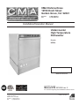
CMA Dishmachines
12700 Knott Street
Garden Grove, CA 92841
Toll Free: Fax:
1- (800) 854-6417
1- (714) 895-2141
Installation/Operation Manual
Undercounter
High Temperature
Dishwasher
Models:
UC65e
UC65e
Machine Serial No.
Issue Date: 4.17.09
Manual P/N 0512865 rev. 0
For machines beginning with S/N W090217876 and above
CMA Dishmachines
12700 Knott Street
Garden Grove, CA 92841
Toll Free: 1 (800) 854-6417
Fax: 1 (714) 895-2141
Printed in the USA
For future reference, record your dishwasher information in the box below.
Model Number__________________________ Serial Number_______________________
Voltage________________Hertz_____________ Phase__________________
Service Agent __________________________________ Tel:______________________
Parts Distributor _________________________________ Tel:______________________
National Service Department
CMA Dishmachines
12700 Knott Avenue
Garden Grove, CA 92841
Toll-free: 1 (800) 854-6417
Fax:
1 (714) 895-2141
ATTENTION:
The model no., serial no., voltage, Hz
and phase are needed to identify your
machine and to answer questions.
The machine data plate is located
on the lower front panel.
Please have this information ready
if you call for service assistance.
COPYRIGHT © 2009 All rights reserved
Printed in the USA
Revision History

Revision History
•
The Revision History can contain part number changes, new instructions, or information that was not available at print time.
•
We reserve the right to make changes to these instructions without notice and without
incurring any liability by making the changes..
•
Equipment owners may request a revised manual, at no charge, by calling CMA Dishmachines at 1 (800) 854-6417.
Revision
Date
4.17.09
Revised
Pages
All
Serial Number
Effectivity
W090217876
Revision
Description
Released First Edition
i
Model Description
Model Description
UC65e
High temperature hot water sanitizing dishwasher with built-in 40°F/22°C rise booster heater.
208-240VAC/60/1
ii
Table of Contents
Table of Contents
Model UC65e Undercounter Dishwasher
Revision History...................................................................................................................i
Model Descriptions...............................................................................................................ii
Installation...............................................................................................1
Receiving.....................................................................1
Electrical Connections.................................................2
Water Connections......................................................4
Drain Connections.......................................................5
Initial Start-up. .........................................................................................6
Booster Fill Switch.......................................................6
Assembly
.......................................................8
Chemical Dispensing Pumps.......................................9
Priming...............................10
Adjusting............................11
Operation................................................................................................................. 13
Normal Wash Mode.....................................................13
Saf-T-Temp..................................................................14
Cleaning and Maintenance........................................................................15
Cleaning.......................................................................15
Maintenance................................................................18
Troubleshooting...........................................................19
Electrical Schematic.............................................................................................. 21
Timer Chart............................................................................................. 22
Fill/Drain Timer -Theory of Operation. ........................................................ 23
iii
Blank Page
This Page
Intentionally
Left Blank
iv
Installation
Receiving
NOTE:
The installation of your dishwasher must be performed by qualified service personnel.
Problems due to improper installation are not covered by the Warranty.
1.
Inspect the outside of the dishwasher carton for signs of damage.
2.
Remove the carton and inspect the dishwasher for damage.
3.
Check for any accessories that may have shipped with your dishwasher.
4.
Move the dishwasher near its permanent location.
CAUTION:
Be careful when lifting and moving the dishwasher to prevent damage to the machine.
NOTE:
The installation of the dishwasher must comply with local health codes.
5.
Compare the installation site utility connections with the dishwasher utility connections and
make sure that they are the same.
6.
The dishwasher can be installed as a free-standing unit or under a built-in counter-top.
The typical counter-top height in most locations is 34" [86cm].
7.
Under counter installations should provide storage space for the dishwasher chemical supply
containers. Containers must not be
placed higher than 10" [25cm] above the floor.
8.
Chemical supply containers should be placed as
close as close to the machine as possible.
9.
Place the dishwasher in its permanent location.
Wall
Counter-top
10. The dishwasher has 4 adjustable feet for
leveling.
11. Level the dishwasher front-to-back and
side-to-side.
34"
[86cm]
Min.
Floor
3" [8cm] Min.
1
Installation
Electrical Connections
WARNING:
Electrocution or serious injury may result when working on
an energized circuit.
Disconnect power at the main breaker or service disconnect
switch before working on the circuit.
Lock-out and tag the breaker to indicate that work is being
performed on the circuit.
ATTENTION
A qualified electrician must connect the main incoming power to the dishwasher in accordance
with all local codes and regulations or in the absence of local codes in accordance with the
National Electrical Code
VERIFY THE CORRECT VOLTAGE IS SUPPLIED TO THE MACHINE
THE CORRECT SUPPLY VOLTAGE IS 115/208-240VAC/60/1.
(See the diagram on next page.)
Main Terminal Block
The Main Terminal Block (MTB) is located on the left-rear corner
of the electrical panel.
2
Installation
Electrical Connections
1. Refer to the connection diagram on the preceding page and the photo below:
2. Machines require a 3-wire plus ground supply which includes a current carrying neutral.
3. Power connections are made at the Main Terminal Block (MTB).
4. The MTB is located on the left-rear corner of the electrical panel behind the front access panel.
(See the illustration on the previous page.)
NOTE:
Provide a 3 foot service loop in the power cable at the back of the dishwasher for service.
To Connect Main Power to the Dishwasher:
1. Remove the lower front access panel of the dishwasher.
2. Locate the electrical mounting panel on the right-side of the machine.
Remove the retaining nut at the top of the panel that holds the panel in place.
3. Lower the panel and pull it forward to gain access the MTB.
4. Feed the power cable through the cable hole located
on the right side, as viewed from the front of the machine,
into the interior of the machine.
5. Make sure the cable passes through the cable mounting
bracket located near the front-center of the
base and secure the cable with a cable connector.
6. Connect the ground wire to the base of the dishwasher
with the ground screw provided next to the
cable mounting bracket.
7. Feed the remaining cable wires to the Main Terminal
Block and connect according to the connection
diagram to the right.
SINGLE PHASE POWER CONNECTION
115/208-240VAC/60/1
GRD
L1
L2
N
115VAC
208-240
VAC
HOW TO CONNECT POWER
From Rear of Machine
1. Check the data plate on the front of the
dishwasher for the voltage of the machine.
2. Remove the lower-front access panel.
Cable Bracket
3. Lower the electrical component bracket.
4. Feed the power cable from the rear of the
dishwasher to the center of the machine
and through the cable bracket.
GRD
To Main Terminal Block
L1
L2
N
5. Connect the ground wire to the base of the
dishwasher using the ground screw located
near the bracket.
6. Feed the power leads to the terminal block.
7. Connect L1, L2 and a currrect-carrying
neutral to the Main Terminal Block.
8. Main Power connections are complete.
Route the supply cable through the cable bracket.
3
Installation
Water Connections
Note
Plumbing connections must comply with national, local plumbing and sanitary codes.
IMPORTANT
Make sure that the flexible water supply and drain hoses are not kinked.
1.
All models have a 6 ft. flexible hot water fill hose with a 3/4" GHT connector.
2.
A 1/2" or larger main incoming supply line should be installed to the dishwasher.
3.
A 1/2" or larger shut-off valve should be installed in the water supply line as close to the
dishwasher as possible for service.
4.
The hot water supply must provide a minimum of 140°F/60°C, measured at the dishwasher for
the 40°F/ 22°C rise booster.
5.
For the 70°F/39°C rise booster the hot water supply must provide a minimum of 110°F/43°C
measured at the dishwasher.
4
Installation
Drain Connections
ATTENTION
Do not connect the drain hose to a disposer. The dishwasher will not drain correctly.
1.
The dishwasher has a 6ft. 3/4" I.D. drain hose. The maximum drain height
connection must not exceed 3 ft.[9 m].
The recommended drain height is 17" [.4 m] or less above the floor.
2.
The drain hose is secured to the rear of the machine by a clamp to maintain a
goose-neck bend in the drain hose.
DO NOT REMOVE THE DRAIN HOSE RETAINING CLAMP.
DO NOT STRETCH THE DRAIN HOSE.
3.
Install the drain hose to a "WYE" drain fitting. Connection to a "TEE" fitting will
prevent the dishwasher from draining completely.
4.
The maximum drain flow is 8 U.S. gpm/7 Imp. gpm/30 L.P.M.
5.
Make sure the drain hose does not kink. Kinks will prevent the dishwasher
from draining completely, and the dishwasher will overflow out the front door.
NOTE: DO NOT CONNECT THE DRAIN HOSE TO A DISPOSER.
THE DISHWASHER WILL NOT DRAIN CORRECTLY.
The dishwasher flexible drain hose
must be connected to a WYE fitting.
Do not connect the dishwasher
flexible drain hose to a TEE fitting.
5
Initial Start-Up
Filling the Booster
ATTENTION
VERIFY THE CORRECT VOLTAGE IS SUPPLIED TO THE MACHINE
THE CORRECT SUPPLY VOLTAGE IS 115/208-240VAC/60/1.
(Refer to the diagram on page 3.)
Note:
The dishwasher contains a built-in booster heater that was drained prior to shipment
and must be filled with water before operating the dishwasher.
Booster Fill Switch
The booster heater is filled using the Booster Fill Switch. It is located behind the lower front access panel
and on the left-side of the bracket that holds the chemical dispensing pumps (see the photos below).
Fill the booster heater:
1.
Make sure that the dishwasher power switch is OFF.
2.
Remove the lower front access panel.
3.
Locate the booster fill switch. It is in the left-center of the electrical component panel.
4.
Make sure the Booster Fill Switch is in the middle position, (OFF).
5.
Turn the water supply and the main power supply on.
DO NOT TURN THE DISHWASHER POWER SWITCH ON.
A) Identify the booster fill switch.
RINSE
WASH
RE
TEMPERATU
ON
OFF
BOOSTER
FILL
Booster Fill Switch
A
6
Initial Start-Up
Filling the Booster (continued)
B) Press and hold the Booster Fill Switch down to the BOOSTER FILL
position until you hear the water spraying inside the dishwasher wash tank,
then release the switch.
RINSE
WASH
RE
TEMPERATU
ON
OFF
BOOSTER
FILL
B
C) Push the switch up to the ON position and release.
The booster tank is filled.
RINSE
WASH
RE
TEMPERATU
ON
OFF
BOOSTER
FILL
C
7
Initial Start-up
Check List
1.
Remove any protective film from dishwasher. Check the interior for foreign material.
2.
Make sure that the dishwasher is permanently located.
3.
Make sure that all utility connections are complete.
4.
Make sure that the flexible drain hose and the hot water fill hose are not kinked.
5.
Make sure that the chemical supply containers are full and that the chemical pick-up tubes
are installed in the proper containers.
6.
Make sure that the sump filter is in place.
7.
Make sure that the overflow tube is installed and firmly seated in the sump.
8.
Make sure that the spray arms are in place and that they spin freely.
9.
Fully close the dishwasher door.
10. Turn hot water supply on and check for leaks in the main water supply piping connected
to the dishwasher.
IMPORTANT
During the initial fill, the flowing pressure of the incoming water
is set to 20-22 PSI.
Install the scrap screen, overflow tube, and spray arms.
Make sure the spray arms turn freely.
8
Initial Start-up
Chemical Dispensing Pumps
ATTENTION
Contact a local chemical supplier for detergent and rinse-aid chemicals. The detergent should be a
non-chlorinated liquid detergent. The chemical dispensing pumps are adjusted by the chemical supplier.
1.
The dishwasher is equipped with a built-in detergent dispensing pump and rinse-aid dispensing
pump. (See the photographs below.)
2.
The pumps are located on the lower panel behind the lower-front access panel.
3.
Each pump is equipped with 6 feet [1.8 m] of pick-up supply tubing, a stiffener tube, and a strainer.
4.
A red label marked DETERGENT is attached to the detergent pump inlet tubing.
5.
A blue label marked RINSE-AID is attached to the rinse-aid pump inlet tubing.
6.
The detergent enters the wash tank compartment through a fitting at the right rear of the wash
compartment (see the illustration on the next page).
7.
The detergent supply should be a non-chlorinated liquid detergent.
8.
The rinse-aid enters the final rinse piping through a fitting located on the upper-left rear side of the
dishwasher. The fitting is located near the vacuum breaker (see the illustration on the next page).
SH
WA
SE
TURE
PERA
RIN
TEM
ON
OFF
TER
OS
BO LL
FI
Rinse-aid
Pump
Detergent
Pump
The dispensing pumps are located behind the
lower-front access panel.
9.
A stiffener tube, strainer and pick-up
tubing are supplied with the built-in
detergent and rinse-aid pumps.
The chemical supplier will choose the appropriate liquid rinse-aid.
10. Your chemical supplier should adjust the dispensers for the supplied product.
11. Place the chemical supply containers as close to the dishwasher as possible.
12. Do not elevate the chemical containers above the finished floor.
9
Initial Start-up
Chemical Dispensing Pumps (continued)
Chemical Injection Points
The illustrations below show the location of the detergent and the rinse-aid injection points.
Detergent
Injection Point
Rinse-aid
Injection
Point
Detergent enters the wash tank compartment through a
fitting on the rear wall of the wash tank compartment.
The rinse-aid enters the final rinse piping at the top-rear of
the dishwasher near the vacuum breaker.
10
Initial Start-up
Chemical Dispensing Pumps
Priming the Chemical Dispensing Pumps
The chemical dispensing pumps must be primed before the dishwasher is operated. A 2-position PRIME
switch is located on the front control panel to do this. The Detergent dispensing pump is primed when
the Prime switch is pushed UP to the DET position. The Rinse-aid dispensing pump is primed when the
Prime switch is pushed DOWN to the R/A position (see below).
DET
R/A
ON
PRIME
EXT. WASH
DRAIN
START
OFF
POWER
Chemical Dispenser Prime Switch
1.
Make sure the chemical containers are full and the correct pick-up tubes are in the containers.
2.
Turn the dishwasher power switch ON. The switch will illuminate and the dishwasher will fill with
water.
3.
Once the fill is complete, open the dishwasher door, then push and hold the prime push button UP
to the DET (detergent) position until detergent is observed entering at the right-rear of the wash
tank compartment.
4.
Push and hold the prime push button DOWN to the R/A (rinse-aid) position for 30-seconds.
Release the push button.
5.
Close the door.
11
Initial Start-up
Chemical Dispensing Pumps
Adjusting the Chemical Dispenser Pumps
The amount of detergent and rinse-aid that are dispensed during the dishwasher cycle are controlled by
adjustable cams on the timer assembly. Variables such as the type of chemicals used and the hardness
of the water supply often require that the timer cam settings must be changed. It is recommended that
the chemical supplier make these adjustments.
(Refer to the illustration below).
Note:
Only the Detergent and the Rinse-aid cams are adjustable. Do not attempt to adjust any other timer cam.
To adjust the chemical dispensing pump timer cams:
1.
Remove the lower-front access panel. The timer assembly is located on the right-side of the
electrical component panel.
2.
Make sure the dishwasher power is OFF.
3.
The detergent timer cam has 2 halves. Hold the stationary right-half of the cam and turn the
left-half of the cam counter-clockwise to increase the amount of detergent that is dispensed.
Turn the left-half clockwise to decrease the detergent dispensed.
4.
The rinse-aid timer cam has 2 halves. Hold the stationary left-half of the cam and turn the right-half
of the cam counter-clockwise to decrease the amount of rinse-aid that is dispensed.
Turn the right-half clockwise to increase the amount of rinse-aid dispensed.
HOMING
CAM
CCW
WASH
PUMP
DRAIN
PUMP
RINSE
VALVE
RGENT
12
-
SAFE-T
TEMP
E AID
DETE
CW
RINSE EXTEND
WASH
AID
PUMP
RINS
+
DET.
PUMP
+
Operation
Normal Wash Mode
Follow the instructions below to operate the dishwasher in a Normal Wash Mode. A Safe-T-Temp feature
holds the dishwasher in a wash mode if the booster heater temperature is below 180ºF/82ºC.
1.
Turn the main power on at the main circuit breaker.
2.
Install the sump filter, overflow tube and spray arms.
3.
Make sure the flexible drain hose and the flexible fill hose are not kinked,
then turn the water supply on.
4.
Close the dishwasher front door.
5.
Push the dishwasher Power Switch to the ON position.The power switch will illuminate and the
machine will fill with water.
6.
Check the pressure gauge as the machine fills and make sure the incoming water pressure is
between 20-22 psi.
7.
Wait 15-minutes for the WASH temperature gauge to indicate a minimum of 150ºF/66ºC.
ATTENTION
At the beginning of the day, run 2 empty cycles before checking the final rinse
operating temperature. The first cycle will take longer than normal because the
water temperature in the booster is low.
8.
Load soiled wares into the dish rack. Place plates, glasses, cups and bowls in a peg rack.
Place utensils in a single layer in a flat-bottom rack. Place pots and pans in a flat-bottom rack.
Do not overload the dish racks.
9.
Slide 1 dish rack into the wash compartment making sure that wares do not interfere with the
rotating spray arms. Do not wash more than 1 dish rack at a time.
10. Close the front door fully, then press and hold the START BUTTON for 1-second. The green
in-cycle light will illuminate and the wash cycle will begin. The wash cycle time runs for
approximately 1-1/2 minutes. (continued on next page)
150°F/66°C
Final Rinse
Pressure
20
0
22
Wash
Temperature
80
0
60
20
80
100
200
100
60
60
20
140
180
CHAMPION INDUSTRIES, INC.
WINSTON-SALEM,NC
0
80
40
40
0
50
10
60
180
20
40
PSI
60
80
40
120
100
160
40
140
160
20
120
100
30
180-195°F
82-91°C
200
20-22 PSI
0
22
Final Rinse
Temperature
The pressure and temperature gauges are located on the lower-left corner
of the lower-front access panel.
13
Operation
Normal Wash Mode (continued)
11. Opening the door when the dishwasher is in-cycle will stop the dishwasher. The cycle will resume
automatically when the dishwasher door is closed fully.
12. The final rinse cycle begins at the end of the wash cycle and runs for approximately 15-seconds Check the
RINSE temperature gauge during the final rinse and make sure that it indicates a minimum of 180ºF/82ºC.
The acceptable range of operation is180-195ºF/82-91ºC.
13. At the end of the rinse cycle, the in-cycle light will go out. Open the door and remove the clean
rack of wares. Repeat steps 8-12 for additional dish racks.
14. Refer to the Cleaning Instructions, "After Each Meal Period or every 8 Hours of Operation", on
page 15 for the procedures to drain and clean the dishwasher.
Safe-T-Temp Mode
The final rinse water temperature must be a minimum of 180ºF/82ºC during the final rinse cycle to ensure that all
wares are sanitized. If for any reason, the hot water temperature in the booster tank cannot provide this temperature,
the dishwasher will enter a Safe-T-Temp Mode of operation and extend the cycle time.
The Safe-T-Temp changes the Normal Operation Mode as described below:
1.
The Safe-T-Temp constantly monitors the water temperature inside final rinse booster.
2.
If the temperature inside the booster heater falls below 180ºF/82ºC then the Safe-T-Temp
will extend the wash cycle time until the booster heater water temperature reaches the proper
temperature.
3.
The in-cycle light will remain illuminated during the Safe-T-Temp Mode.
4.
The RINSE water temperature gauge must be monitored to ensure that a minimum of
180ºF/82ºC is maintained during the rinse cycle.
5.
The temperature range for the final rinse water is180-195ºF/82-91ºC.
6.
An extraordinarily long wash cycle may indicate a low incoming water temperature or a
problem with the booster heater operation.
DO NOT REMOVE WARES UNTIL THE FINAL RINSE CYCLE HAS
SANITIZED THE WARES AND THE GREEN CYCLE LIGHT GOES OUT.
Extended Wash Mode
The Extended Wash Mode is used to wash heavily soiled items such as pots, pans and other wares that
require more washing time than the standard 100-second Normal Wash Mode.
The dishwasher will remain in the Extended Wash Mode until the operator exits the mode.
1.
Load a dish rack into the dishwasher, close the door.
2.
Press and hold the START button for 1-second then release.
3.
The green in-cycle light will illuminate and the dishwasher will begin a normal wash cycle.
4.
Press the EXT WASH button to place the dishwasher in the Extended Wash Mode.
5.
The green extended wash light will illuminate indicating that the machine is in the
Extended Wash Mode.
6.
The dishwasher will continue to wash until the operator presses the EXT WASH button again.
7.
Press the EXT WASH button. The green extended wash light will go out indicating that
the dishwasher has returned to the Normal Wash Mode.
8.
The dishwasher will finish the wash cycle and perform a final rinse of the wares.
14
Cleaning and Maintenance
Cleaning
After Each Meal Period or every 8 Hours of Operation.
1.
Press the lighted power switch to the OFF position. The power switch light will go out.
2.
Open the door and remove the overflow tube from the wash tank sump.
3.
Inspect and clean the overflow tube rubber seal
4.
Close the door.
5.
Push and hold the drain switch until all of the water has drained.
6.
Remove the sump filter carefully to keep the soil or waste particles from falling into the sump.
7.
Clean the sump filter by rinsing with clean water.
Be sure to back-flush the filter.
Do not strike the filter against solid objects.
8.
Check the sump for foreign material and clean as required.
9.
Replace sump flter and the overflow tube.
10. Make sure that spray arms turn freely.
11. Check the chemical containers and refill as required.
12. Close the door and turn the ON/OFF switch to ON and return to normal operation mode.
Overflow
Tube
Heating
Element
Overflow
Seal
Sump
Filter
Sump
15
Cleaning and Maintenance
Cleaning
At the End of the Day
1.
Perform Steps 1-8 on the previous page.
2.
Remove the upper and lower rinse and wash spray arms. The spray arms are interchangeable.
3.
Unscrew the rinse arm pin (A). Remove the rinse arm assemblies
4.
Clean the final rinse arm nozzles using a small paper clip (B).
5.
Remove the rinse arm end plugs (C) if necessary, and flush the rinse arm with clean water.
6.
Re-install the rinse arm end plugs if they were removed.
7.
Remove the wash spray arms and flush with clean water.
8.
DO NOT USE STEEL WOOL TO CLEAN THE INTERIOR OF THE MACHINE.
9.
Contact the chemical supplier for de-liming if required (see next page).
10. Wipe the interior and exterior of the machine with a soft cloth and a mild detergent.
DO NOT HOSE THE EXTERIOR OF THE MACHINE WITH WATER.
11. Reassemble the dishwasher and leave the door open to allow overnight drying.
Paper Clip
B
End
Plug
C
Wash Spray arm
D
16
Rinse Arm Pin
A
Cleaning and Maintenance
De-liming
Minerals accumulate on the interior surfaces of the dishwasher. The deposits have a white haze
and, in cases of heavy accumulation, may appear as a granular solid. The generic name for mineral
deposits is lime. The removal of lime deposits is called de-liming. Your dishwasher should be delimed regularly; how often will depend on the mineral content of your water.
Inspect your machine interior for lime deposits. If deliming is required, a de-liming agent should be
used for best results in accordance with the chemical supplier's instructions.
Danger:
Death or serious injury may result when de-liming solution is mixed with sodium hypochlorite
(chlorine bleach) sanitizing agent. Mixing may cause hazardous gases to form.
De-liming solution and other acids must never be mixed with chlorine, iodine, bromine, or fluorine.
Caution:
Skin contact with de-liming solutions can cause severe irritation and possible chemical burns.
Always wear protective clothing and googles when handling chemicals.
Attention:
Contact your chemical supplier for specific safety procedures and instructions for the use of
the de-liming solution supplied for the dishwasher.
De-liming solution or other chemicals are not supplied by the dishwasher manufacturer.
Overflow
Tube
Heating
Element
Overflow
Seal
Sump
Filter
Sump
17
Cleaning and Maintenance
Maintenance
Follow the maintenance schedules below to keep the dishwasher operating most efficiently.
Daily Maintenance
1.
Check all of the wash arm and rinse arm spray jets and clean as necessary.
2.
Make sure that the water supply is on and that the drain is not clogged.
3.
Check the temperature gauges and/or displays to ensure that they are operating.
4.
Make sure that dish racks are in good condition.
5.
Check the chemical containers and refill as required.
6.
Follow the cleaning procedures given above.
Weekly Maintenance
1. Perform Steps 1-5 in the Daily Maintenance.
2. Inspect water lines for leaks.
3. Check for water leaks underneath the dishwasher.
4. Make sure the flexible water fill and drain hoses are not kinked.
5. Make sure that the dishwasher is level.
6. Clean accumulated lime deposits from the wash tank heating element.
7. Inspect the scrap screen and replace it if damaged.
8. Check the spray arms and replace or repair if damaged.
9. Clean the chemical dispenser pick-up tubing for the detergent and rinse-aid pumps.
To clean the pick-up tubing:
1. Remove the pick-up tubes from their containers.
2. Place each tube in a separate container of hot water.
3. Press and hold the PRIME button up in the DET position until water flows into the wash tank
compartment.
4. Press and hold the PRIME button down in the RINSE position until water flows into the wash
tank compartment.
5. Return the pick-up tubes to their containers.
6. Run 3 empty dishwasher cycles to flush any chemicals from the dishwasher wash
compartment.
7. Push and hold the chemical prime button to prime the chemical pumps.
18
Troubleshooting
Troubleshooting
Follow the troubleshooting guide below in the event that your dishwasher does not operate as
expected. Perform the basic checks below before calling an authorized service agent:
1.
Make sure that the main water supply is turned on.
2.
Make sure that the main power is turned on.
3.
Make sure that the flexible water fill and drain hoses are not kinked.
Condition
Cause
Solution
Dishwasher will not run.
Door not closed.
Main power OFF.
Dishwasher OFF.
Close door completely.
Check breaker on panel.
Turn dishwasher ON.
Low or no water.
Main water supply off.
PRV setting incorrect
Solenoid strainer clogged.
Solenoid valve defective.
Open supply valve.
Adjust the PRV setting
Clean strainer.
Contact Service Agent.
Chemicals won’t feed into
dishwasher.
Chemical supply low.
Pick-up tube clogged
Supply tubing damaged.
Supply tubing kinked.
Refill chemical container.
Clean/replace tube.
Replace tubing.
Straighten tubing.
Poor wash results.
Wares incorrectly loaded.
in dishrack.
Reposition wares or
reduce amount of wares.
Clogged sump filter.
Clogged spray arms.
Clean sump filter.
Clean spray arms.
Detergent injector not
feeding.
Replace squeeze tube or
clean tubing and pick-up
tube.
Thermostat defective.
Contact Service Agent.
Detergent motor defective.
Contact Service Agent
Water temperature low.
Contact Service Agent
Safe-T-Temp extends wash
mode to allow final rinse
water booster temperature
to reach 180˚F/82˚C.
Dishwasher is operating in
the Extended Wash Mode.
Contact Service Agent
because booster
thermostat is defective.
Dishwasher stays in
wash cycle.
Press the Extended Wash
button 1 time. The Extended
Wash Indicator light will go
out, the wash cycle will
resume where it left off and
perform a final rinse cycle.
19
Blank Page
This Page
Intentionally
Left Blank
20
Model UC65e - Electrical Schematic
TO CUSTOMERS DISCONNECT SWITCH
PER LOCAL ELECTRICAL CODE
115-208/230V/1PH 60HZ
L1 L2
PS
1
BFS
1L1
N
GND
L1
1
TT
TS
3
4
5
L2
1L2
WHTR
POL
7
10
25
1
1
HC1 1H2
19
1
HC1
DOOR
SWITCH
9
DRAIN
SWITCH
6
8
CPS
N
1H1
EWL
EXT. WASH SWITCH
1HTR
BOOSTER HEAT
208/230 VAC
4 kW
11
START SWITCH
13
26
SR1
23
SR1-2
WP
WPR
12
SR
2
6
2
2
13
1
3
HOMING
CAM
15
3
EXT. WASH
CAM
16
3
TM
SAFETY
TEMP
CAM
3 WASH PUMP
3
FILL/RINSE
2
DETERGENT
2
R/A
RV
8
DEP
9
1L1
1
DOOR
SW
HOT
RAP
TIMER
27
6
BFS
BS
BT
CL
CPS
DEP
DP
EWL
EWS
GND
HC1
1HTR
POL
PS
RAP
RV
SR
TM
TS
TT
WHTR
WPR
DP
7
1
MAXIMUM OVERCURRENT
PROTECTION 30 AMPS
WPR
19
2 DRAIN PUMP
MINIMUM CIRCUIT AMPACITY
30 AMPS
CL
17
1
2
DIAGRAM STATE
END OF CYCLE
POWER-OFF
DOOR-OPENED
RINSE
DRAIN
Model UC 65e
HIGH TEMP UNDERCOUNTER
19
FILL TIMER MODULE
N
SW. PWR.
BOOSTER FILL SWITCH
BOOSTER SAFETY THERMOSTAT
BOOSTER THERMOSTAT
CYCLE LIGHT
CHEMICAL PRIME SWITCH
DETERGENT PUMP
DRAIN PUMP
EXTENDED WASH LIGHT
EXTENDED WASH SWITCH
GROUND
BOOSTER CONTACTOR
BOOSTER HEATER
POWER ON LIGHT
POWER ON SWITCH
RINSE AID PUMP
RINSE VALVE
START RELAY
TIMER MOTOR
TANK HEAT SAFETY THERMOSTAT
TANK HEAT THERMOSTAT
WASH TANK HEATER
WASH PUMP RELAY
DATE
25-FEB-09
10
NUMBER/REV
UC65e/0512867/REVA
10
1
BT
BS
21
22
HC1
N
21
22
CMA Dishmachines
8 SAFE-T-TEMP
7 EXTENDED WASH
6 RINSE AID PUMP
5 DET PUMP
4 RINSE VALVE
3 DRAIN PUMP
2 WASH PUMP
1 HOMING CAM
TIME (SEC.)
0
6
10
20
30
40
UC65e
50
60
TIMING CHART
70
80
90
100
110
05CTIME
DRAWING NO.
120
Timer Chart - Model UC65e
Theory of Operation - Fill/Drain Timer
Fill/Drain Timer - Theory of Operation
The Fill/Frain Timer provides both automatic fill and semi-automatic drain functions for the
dishwasher. It is located on the back of the electrical component panel and it operates as follows:
Fill
1. Main power, (115VAC), must be present at the Hotline and Neutral terminals of the fill/drain timer.
2. Turning the machine ON/OFF switch ON, sends 115VAC to the "SW Power" terminals which
activates the initial fill.
3. The rinse valve is activated for 70-seconds.
4. The drain pump also operates for the same amount of time. This prevents any overflow conditions
if the wash tank had not been drained previously.
5. If the door is opened during the fill cycle, then all functions are suspended and will continue from
where they left off once the door is closed.
6. To prevent false fills due to brief power interruptions, the following safety measures are built into the
operation of the Fill/Drain Timer:
a. Power must be present at the Hotline and Neutral terminals for 5-seconds before the signal from turning the machine ON/OFF switch ON is accepted.
b. A fill will not happen unless the machine ON/OFF switch is OFF for 5-seconds before being switched ON without interruption.
Dra
in
Sw
Do Powe
or
SW r
Fill
Ho
tlin
Ne
e
utra
l
Fill/Drain Timer
(shown enlarged)
23
Blank Page
This Page
Intentionally
left Blank
25